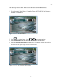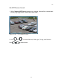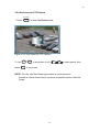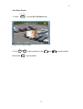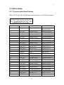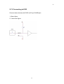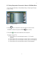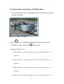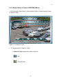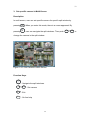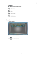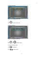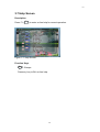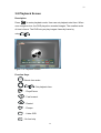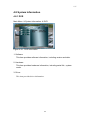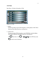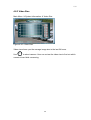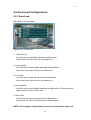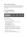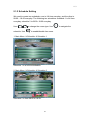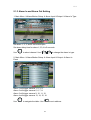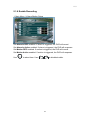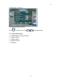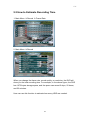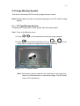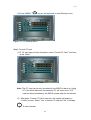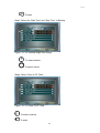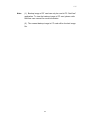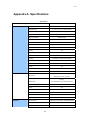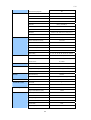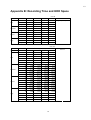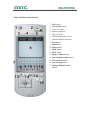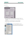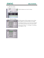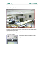
1
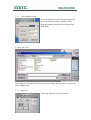
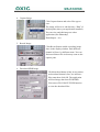
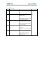
MULTI-CHANNEL
DIGITAL VIDEO RECORDER
Version 92040729
1
Introduction
This manual is for the users who attempt to use Multi-channel Digital
Video Recorder (MDVR). It illustrates features, installation guide, connecting to
peripherals, and Graphic User Interface (GUI) operation. Please familiarize
yourself with the contents in this manual before using the DVR. Make sure that
you have referred to an expert when opening the outer case for repair or
installing HDD. If you have any inquiries or questions on the products, please
consult to your local dealer.
When you have received your new MDVR system, inspect the contents of the
package to verify that all units have been shipped before you begin the
installation process.
Caution Several connectors on the rear panel of the MDVR system are keyed
and must be properly aligned before inserting them into the port. Failure to
align the plug can damage connector’s functionality.
2
Caution
WARNING
To prevent fire or electric shock, do not expose this product to rain or moisture.
Dangerous high voltages are present inside the enclosure. Do not open the
cabinet. Refer servicing to qualified personnel only.
The lightning flash with arrowhead symbol, within an equilateral
triangle, is intended to alert the user to the presence of un-insulated
“dangerous voltage” within the product’s enclosure that may be of
sufficient magnitude to constitute a risk of electric shock to persons.
The exclamation point, within an equilateral triangle, is intended to
alert the user to the presence of important operating and
maintenance (servicing) instructions in the literature accompanying
the appliance.
3
About This Product
USA
This product has been tested and found to comply with the limits of a Class A
computing device pursuant to part 15 of the FCC rules, which are designed for
reasonable protection against harmful interference when operated in a
commercial environment.
Europe CE
This product adheres to the requirements for radiated emission according to
the limits of the European Standards.
Liability
This manual has been taken every care for user when preparation. If user
detected any inaccuracies or omissions, please contact your local vendor for
more information.
Legal Consideration
Camera surveillance may be against the laws that vary from country to country.
Please check the laws in your local region before using this product for
surveillance purpose.
Electromagnetic Compatibility (EMC)
This product can generate and radiate radio frequency energy, and if not
installed or used followed by the instruction manual, may cause interference to
radio communications. Operation of this product in a residential area is likely to
cause interference, in which case the user will be required to take whatever
measure and cost to correct the interference. To ensure compliance with EMC,
shielded cables should be required to use with this product.
4
Table of Contents
Chapter 1 Products Overview 9
1.1 Unpacking...........................................................................................9
1.2 DVR Overview .................................................................................. 11
1.2.1 DVR Functions and Features ................................................. 11
1.2.2 DVR Front Panel.....................................................................12
1.2.3 DVR Rear Panel .....................................................................13
1.3 Multi-Keyboard Overview..................................................................14
1.3.1 Keyboard Front Panel.............................................................14
1.3.2 Keyboard Rear Panel .............................................................15
1.4 Remote Controller.............................................................................16
Chapter 2 Hardware Installations with DVR 17
2.1 Cautions in Installation......................................................................18
2.2 HDD Installation ................................................................................19
2.3 Multi-Keyboard & MDVR Connections ..............................................20
2.3.1 Single Multi-Keyboard with Single MDVR Connection............20
2.3.2 Single Multi-Keyboard with Multiple MDVRs Connection........20
2.3.3 Multiple Multi-Keyboards with Single MDVR Connection........21
2.3.4 Multiple Multi-Keyboards and MDVRs Connection .................21
2.4 Video Output Connection..................................................................23
2.4.1 Connect with CCTV Monitors .................................................23
2.4.2 Connect with TV .....................................................................23
2.4.3 Connect with CRT or LCD Monitors........................................24
2.5 Network Installation...........................................................................25
2.5.1 Connect with DVR ..................................................................25
2.5.2 Setup LAN Configuration in DVR Main Manu .........................25
2.6 Cameras Installation .........................................................................26
2.6.1 Connect with Cameras ...........................................................26
2.6.2 Setup RS-485 in Main Menu to Control Cameras...................26
2.6.3 Setup Camera ID & PTZ Camera Enable in DVR Main Menu 27
2.6.4 PTZ Camera Control...............................................................28
2.6.5 Set Preset for PTZ Camera ....................................................29
2.6.6 Goto Preset ............................................................................30
2.6.7 Setup Camera Adjust in DVR Man Manu................................31
2.6.8 Setup Camera Action in DVR Main Manu...............................32
2.6.9 Setup Camera Title in DVR Main Manu ..................................33
2.6.10 Setup Sequence Time in DVR Main Manu ...........................34
5
2.7 Alarm Setup ......................................................................................35
2.7.1 Connect with Alarm Devices ...................................................35
2.7.2 Connecting to DVR .................................................................36
2.7.3 Setup Respondent Cameras for Alarm in DVR Main Menu ....37
2.7.4 Setup Alarm Out Enable in DVR Main Menu ..........................38
2.7.5 Setup Alarm In Type in DVR Main Menu ................................40
2.7.6 Setup Alarm Response in DVR Main Menu ............................43
2.7.8 Setup Alarm List in DVR Main Menu.......................................45
2.7.9 Setup Motion in DVR Main Menu ...........................................46
2.7.10 Setup Alarm/Motion Setup in DVR Main Menu .....................47
Chapter 3 Basic Operations
48
3.1 Single Screen ...................................................................................48
3.2 Single Screen with Zooming .............................................................49
3.3 Display Screen..................................................................................50
3.4 Sequencing Screen ..........................................................................53
3.5 Main Menu Screen............................................................................54
3.6 List Screen........................................................................................55
3.7 Help Screen ......................................................................................58
3.8 Playback Screen...............................................................................59
3.9 Freeze...............................................................................................60
3.10 Keyboard Lock................................................................................60
Chapter 4 Menu Setup
62
4.1 Main Menu Overview ........................................................................62
4.1.1 Menu Tree ..............................................................................64
4.2 Camera .............................................................................................65
4.2.1 Camera Adjust ........................................................................67
4.2.2 Camera Action ........................................................................68
4.2.3 Camera Title ...........................................................................69
4.2.4 Camera Sequence Time .........................................................70
4.3 Display and Language ......................................................................71
4.3.1 Screen Center Point & Size ....................................................71
4.3.2 Date/Time Position .................................................................72
4.3.3 Camera Title Type...................................................................73
4.3.4 Date/Time Display ..................................................................74
4.3.5 Clock Mode.............................................................................75
4.3.6 Anti-Flicker..............................................................................76
4.3.7 Test Pattern.............................................................................77
4.3.8 Language................................................................................78
6
4.4 Record ..............................................................................................79
4.4.1 Record Setup..........................................................................79
4.4.2 Frame Rate.............................................................................81
4.5 Alarm/Motion Setup ..........................................................................84
4.5.1 Alarm In Event ........................................................................84
4.5.2 Alarm Out Enable....................................................................85
4.5.3 Alarm In Type..........................................................................87
4.5.4 Alarm Response .....................................................................88
4.5.5 Alarm List................................................................................90
4.5.6 Motion Setup ..........................................................................91
4.5.7 Alarm/Motion Enables.............................................................93
4.6 Schedule...........................................................................................93
4.7 Installer Setup...................................................................................96
4.7.1 Date/Time Setup.....................................................................96
4.7.2 LAN Setup ..............................................................................97
4.7.3 RS-485 Setup .........................................................................98
4.7.4 Camera ID Setup ....................................................................99
4.7.5 Password Setup ...................................................................100
4.7.6 Password Management ........................................................101
4.7.7 Auto Demo............................................................................103
4.7.8 Make Boot Disk.....................................................................104
4.7.9 Compress Information ..........................................................105
4.8 System Information.........................................................................107
4.8.1 DVR ......................................................................................107
4.8.2 Disk.......................................................................................108
4.8.3 Video Size ............................................................................109
4.9 Save/Load Configurations............................................................... 110
4.9.1 Save/Load ............................................................................ 110
Chapter 5 System Operation 111
5.1 How to Set Recording ..................................................................... 111
5.1.1 Sample System Configuration .............................................. 111
5.1.2 Schedule Setting................................................................... 113
5.1.3 Alarm In and Alarm Out Setting ............................................ 114
6.1.4 Motion Detection Setting....................................................... 116
5.1.5 Frame Rate, Quality, and Recording Time Setting................ 117
5.1.6 Enable Recording ................................................................. 119
5.1.7 Check Recording ..................................................................120
5.2 How to Estimate Recording Time....................................................121
7
5.3
Image Backup System ...............................................................122
5.3.1
CF Card Backup System.................................................122
Chapter 6 Trouble Shooting
126
6.1 Installation.......................................................................................126
6.1.1 The DVR is not power on......................................................126
6.1.2 Power is on, but the DVR dose not operate..........................126
6.1.3 Images are not showing on the monitor................................126
6.1.4 The picture quality on the monitor is poor.............................126
6.2 Recording .......................................................................................127
6.2.1 The DVR will not start recording ...........................................127
6.2.2 The DVR can not perform alarm recording ...........................127
6.3 Playback .........................................................................................127
6.3.1 The DVR can not perform playback......................................127
6.4 Others .............................................................................................127
6.4.1 The DVR will not detect motion.............................................127
Appendix A: Specifications 128
Appendix B: Recording Time and HDD Space
131
Appendix C: Glossary 132
8
Chapter 1 Products Overview
1.1 Unpacking
Please place the product on a flat surface to inspect if there is any part
missing among the following items list.
Item
Name and Description
Pcs
1
Mainframe
*1
2
Front Keyboard
*1
3
IR Remote controller
*1
4
AAA NO.4 Battery: for IR Remote controller
*2
5
User’s Manual
*1
6
Rack Mount Ears
*2
9
7
RS-485 Cable 40 CM: used to connect Mainframe and Front
Keyboard
*1
8
AC Power Cord
*1
9
IDE Cable 40CM
*2
Note: If there any part is missing or damaged, please contact your local vendor
as soon as possible.
10
1.2 DVR Overview
1.2.1 DVR Functions and Features
Key Features:
z Reliable and Stable Stand-Alone System
z Individual Unit Accommodates 8/16 Camera Inputs
z Simultaneous Real-Time Recording, Live Images, Playback and
Networking
z MPEG2-Like and JPEG Compression Algorithms
z 16 Alarm Inputs, 4 Alarm Outputs And 1 Relay Output
z Programmable Recording Schedule and Frame Rate Setting
z High-Speed Searching by Time or Events
z Remote Viewing, Access and Control via LAN/WAN/INTERNET
z Support Various PTZ Cameras
z Support RAID Disk (Option)
z CF Card Backup Mode
z Remote 16-Channel Playback
z Evidence Preservation Lock
11
1.2.2 DVR Front Panel
1 Power Indicator
This light Indicates the power status of the DVR.
2 RS-485 Connector
This port is a socket for RS-485 of front keyboard..
3 IR Receiver
This receiver is for infrared remote controller,
NOTE: keep the receiver from disturbs for IR remote
controller.
4 Compact Flash (CF) This socket is for user inserting a CF Card to backup
Card Socket
files from HDD or internal CF Card.
NOTE: Please don’t remove CF Card while power
on.
5 CF Card Indicator
This light Indicates the CF card status of the DVR.
6 HDD Indicator
This light Indicates the HDD status of the DVR.
7 Reserved CDRW /
DVDRW Socket
Only Advanced Model will come with
CDRW/DVDRW driver.
12
1.2.3 DVR Rear Panel
1 Video-In Looping and
Video-Out Connector
This BNC connector is used to connect a camera
or video output of another DVR.
2 Dipswitch
This dipswitch sets Video Looping Terminal
Resistor.
Note: Set ON, if there is no video looping.
3 Power Switch
This button sets power ON or OFF.
4 Power Core Connector
Power Core input.
5 VGA Out Connector
Provides VGA signal.
6 S-Video Out Connector Provides S-Video signal.
7 BNC Out Connector
Provides a composite video signal.
8 VGA/BNC Switch
Switch VGA or BNC.
9 NTSC/PAL Switch
Switch NTSC or PAL
10 LAN Port Connector
Provides a standard RJ-45 socket for 10/100
Mbps Ethernet networks.
11 RS-485 Port Connector This socket is a RJ-11 connector. It provides a
RS-485 control signal port.
12 ALARM I/O Connector
Receives/Provides alarm I/O signals.
13 IDE RAID Connector
(Optional). IDE RAID connector port.
13
1.3 Multi-Keyboard Overview
The Multi-Keyboard is designed for User(s) more conveniently to control the
MDVR(s).
1.3.1 Keyboard Front Panel
3
4
1
2
1
2
3
4
5
6
8
7
PO WE R
S E T P RE S E T
GO T O P RE S E T
F1
F3
F2
F4
F5
SEQ
1
2
3
4
5
6
7
8
11
12
15
16
9
ZOOM
MENU
ENT ER
ESC
13
14
5
1.
2.
3.
4.
5.
6.
7.
8.
6
I R IS
FOCUS
7
Power Indicator
DVR ID Buttons
DVR ID Indicators
Keyboard control Functions
Channels Control Buttons
Playback Control Buttons
PTZ Cameras Control Buttons
Encoder
14
8
1.3.2 Keyboard Rear Panel
1 2
1. Power Cord Jack
2. RJ11 Connector (for RS485)
123 456
Pin no Pin define
1
No Connected
2
DC +12V
3
GND
4
DATA A (+)
5
DATA B (-)
6
No Connected
15
1.4 Remote Controller
1
Provide basic function operations.
2 Replace the Keyboard encoder Knob.
3
Basic operation keys.
4 Alarm key. Press this button to trigger
alarm signals to the DVR.
5
Provide playback operation.
6
Function keys for setting menu
7
Function keys for setting menu
8
Select video channel directly.
16
Chapter 2 Hardware Installations with DVR
17
2.1 Cautions in Installation
Severe impact or vibration may cause malfunction.
Avoid a direct ray of light, and keep the safe
distance between crowded place and the product
as well as its assemblies.
Be careful not to insert any conducting material in
the ventilation space of product.
Avoid places with strong magnetic or electrical
field, or places near a radio or TV.
Always keep the place dust-free when installing or
moving DVR.
18
2.2 HDD Installation
To install Hard Disk for DVR, make sure turn off the power switch of the DVR
rear panel and pull off the power plug from the socket first. Afterward using
cross screwdriver removes all screws around the case to open the DVR’s
upper case, and then follow the three steps below to install the Hard Disk for
DVR.
STEP 1 Set IDE selectable
jumper correctly as
default
configuration on the
HDD before
installation. (It must
refer to HDD user
guide)
Please note the one
is set to Master, the
other one is Slave,
and no HDD brand
is limited.
I DE Soc ket f or HDD2
D1
HD
D2
HD
I DE Sock et f or HDD1
19
STEP 2 Use IDE Cables to
connect with HDDs
and IDE sockets.
2.3 Multi-Keyboard & MDVR Connections
Use Multi-keyboard RS-485 port to connect MDVR’s front RS-485 port. There
are 4 variable connections for MDVR(s) and Multi-Keyboard(s):
2.3.1 Single Multi-Keyboard with Single MDVR Connection
123 456
2.3.2 Single Multi-Keyboard with Multiple MDVRs Connection
RS
-4
85
BU
S
DVR8
.
.
.
Multi - Keyboard
20
.
.
2.3.3 Multiple Multi-Keyboards with Single MDVR Connection
RS
-4
85
BU
S
Multi- Keyb oa rd 8
.
.
.
.
Multi - Keyboard 3
Multi - Keyboard 2
2.3.4 Multiple Multi-Keyboards and MDVRs Connection
RS
-4
85
BU
S
Multi- Keyb oa rd 8
.
.
.
.
DVR8
.
.
Multi - Keyboard 3
Multi - Keyboard 2
21
.
.
.
2.3.5 Multi-keyboard with Multiple DVRs ID Setup
While user tries to control multiple DVRs to do different job, user must set up
each connected DVRs’ different ID in Main Menu first.
To set up DVR’s ID for keyboard, simply go to the Main menu path:
Main Manu Æ Installer Setup Æ RS-485
Figure 2.3.5: DVR ID Setup
Use
to move cursor for selecting the ID section. Press
seconds and use
-
+
PROG
key for 3
to set up DVR ID number (0~7). Then, press
PROG
key for 3 seconds again and press the keyboard ID key (1~8)
below the LEDs numbers on the keyboard).
(the buttons
NOTE: The MDVR ID number 0~7 are with corresponding Keyboard ID 1~8. For
example, if set DVR ID is 5, then press keyboard ID button number 4.
22
2.4 Video Output Connection
Video output connection ports all are on the DVR’s rear panel.
2.4.1 Connect with CCTV Monitors
Use standard “TV Out” BNC Port on the DVR real panel
2
1
1. Video
2. Ground
2.4.2 Connect with TV
Use standard S-Video Port
2
1
1.
2.
3.
4.
3
4
C Ground
C (Chrominance)
Y Luminance + Sync
Y Ground
23
24
2.4.3 Connect with CRT or LCD Monitors
Use standard VGA Port
(At the DVR)
(At the monitor cable)
z
z
15 PIN HIGHDENSITY D-SUB FEMALE at the DVR.
15 PIN HIGHDENSITY D-SUB MALE at the monitor cable.
Pin
Name
Dir
Description
1
RED
Red Video (75 ohm, 0.7 V p-p)
2
GREEN
Green Video (75 ohm, 0.7 V p-p)
3
BLUE
Blue Video (75 ohm, 0.7 V p-p)
4
ID2
Monitor ID Bit 2
5
GND
Ground
6
RGND
Red Ground
7
GGND
Green Ground
8
BGND
Blue Ground
9
KEY
-
Key (No pin)
10 SGND
Sync Ground
11 ID0
Monitor ID Bit 0
12 ID1 or SDA
Monitor ID Bit 1
13 HSYNC or CSYNC
Horizontal Sync (or Composite Sync)
14 VSYNC
Vertical Sync
15 ID3 or SCL
Monitor ID Bit 3
24
25
2.5 Network Installation
2.5.1 Connect with DVR
Use RJ-45 port on the DVR’s rear panel to connect with network. Network
function provides user to remote view the DVR’s image on a PC by the
NetView application. To install the Network for DVR, please insert the LAN
cable into RJ-45 port on the DVR rear panel.
LAN Connector
LED2 The
LED1
1234 5678
pin-out of the RJ-45 jack is the same as a standard
Ethernet UDP jack.
LED1: YELLOW LIGHT Indicates the MESSAGE
Transaction.
LED2: GREEN LIGHT Indicates the LAN PORT ON LINE.
2.5.2 Setup LAN Configuration in DVR Main Manu
1. Go to the path: Main Manu Æ Installer Setup Æ LAN
Figure 2.5.2: LAN Configuration
2. Use
and Encoder (
) to set IP, Mask and Gateway values.
Note: The numbers of IP, Mask and Gateway in Figure 2.5.2 is an example. To
set LAN configuration, users need to contact their local internet provider or the
company network administrator for correct information.
25
26
2.6 Cameras Installation
2.6.1 Connect with Cameras
Use “In” standard BNC Port on the DVR real panel
2
1
1. Video
2. Ground
2.6.2 Setup RS-485 in Main Menu to Control Cameras
1. Go to the path: Main Menu Æ Installer Setup Æ RS-485
Figure 2.6.2: RS-485
+ to change value.
2. Use
to select item. Use 3. Baud Rate: DVR support 7 kinds of PTZ camera manufacturers protocols,
User needs to refer Dome’s manufacturer manual to set Baud Rate
4. ID: The ID panel here is for DVR’s ID.
5. Protocol: select the brand of the PTZ camera.
26
27
2.6.3 Setup Camera ID & PTZ Camera Enable in DVR Main Menu
1. Go to the path: Main Menu Æ Installer Setup Æ RS-485 Æ Set Camera
RS-485 Æ Camera #
Figure 2.6.3.1: Set camera ID
+ to change values.
2. Use
to select items. Use 3. Set the Camera ID as the same as the switch ID of the dome.
4. Set the Camera 485 Enable enabled for PTZ camera. Dome icon will be
showed on the upper right corner of the screen.
Figure 2.6.3.2: Set Camera 485 Enable
27
28
2.6.4 PTZ Camera Control
1. When Camera 485 Enable has been set enabled, there will be a dome label
on the upper right corner in the full screen mode:
Figure 2.6.4: PTZ Camera Control
2. Use
Use
or
+
-
to control PAN left, PAN right, Tilt up, and Tilt down.
to zoom in/out.
28
29
2.6.5 Set Preset for PTZ Camera
SET PRESET
1. Press
to enter Set Preset mode.
Figure 2.6.5: Set Preset for PTZ Camera
2. Use
press
1
ENTER
~ 16
to set preset or use
-
+
to select preset, then
to set preset.
NOTE: For Lilin, use the following procedure to set preset point.
Procedure: Recall Goto Preset, set dome at specific location, then Set
Preset.
29
30
2.6.6 Goto Preset
G OTO PRESET
1. Press
to enter Go to Preset mode.
Figure 2.6.6: Goto Preset
2. Use
1
then press
~ 16
ENTER
to go to preset or use
to go to preset.
30
-
and
+
to select preset,
31
2.6.7 Setup Camera Adjust in DVR Man Manu
This function is to set batter picture quality for user.
1. Go to the path: Main Menu Æ Camera Æ Camera Adjust
Figure 2.6.7: Camera Adjust.
2. To set 4 parameters in Camera Adjust function:
(1) Brightness:
Use
-
+
keys to adjust brightness of a camera.
-
+
keys to adjust contrast of a camera.
-
+
keys to adjust hue of a camera.
+
keys to adjust saturation of a camera.
(2) Contrast:
Use
(3) Hue:
Use
(4) Saturation:
Use
-
31
32
2.6.8 Setup Camera Action in DVR Main Manu
This feature is to set the state of cameras.
1. Go to the path: Main Menu Æ Camera Æ Camera Action
Figure 2.6.8: Camera Action.
2. To set the camera condition:
(1) Install:
Use this item to specify if a camera is installed or not installed.
If this item is set for off (
this item is set for on (
), meaning the camera is NOT installed. If
), meaning the camera is installed.
(2) Covert:
This feature removes cameras form all live displays while continuing
to record them. The users are unaware that the camera is being
recorded. To view playback images of covert cameras need to be
authorized. Use this item to specify if a camera is covert. If the
camera is covert, user needs to be authorized to see the image of the
camera.
NOTE: Covert switch (item 4) must be enabled (
).
(3) Sequence Ch:
Use this item to specify which camera should be displayed
32
33
sequentially in the sequencing mode.
(4) Covert Switch:
Use this item to disable/enable the function covert (item 2).
: Function covert (item 2) is disabled.
: Function covert (item 2) is enabled.
2.6.9 Setup Camera Title in DVR Main Manu
1. Go to the path: Main Menu Æ Camera Æ Set Camera Title Æ Camera #
Figure 2.6.9: Set Camera Title
2. Use
and
ENTER
keys to edit the title of each camera.
33
34
2.6.10 Setup Sequence Time in DVR Main Manu
This function is to set changing timer for sequence display mode.
1. Go to the path: Main Menu Æ Camera Æ Sequence Time
Figure 2.6.10: Sequence Time.
2. Use
-
+
keys to adjust 1~255 seconds in Sequence Time panel.
34
35
2.7 Alarm Setup
2.7.1 Connect with Alarm Devices
Alarm I/O Port is 25-pin D-SUB female type connector on the DVR rear panel.
DB 25 PIN NO
Name
FUNCTION
1
ALM_IN1
SENSOR INPUT
2
ALM_IN3
SENSOR INPUT
SENSOR SINGAL 3
3
ALM_IN5
SENSOR INPUT
SENSOR SINGAL 5
4
ALM_IN7
SENSOR INPUT
SENSOR SINGAL 7
5
ALM_IN9
SENSOR INPUT
SENSOR SINGAL 9
6
ALM_IN11
SENSOR INPUT
SENSOR SINGAL 11
7
ALM_IN13
SENSOR INPUT
SENSOR SINGAL 13
8
ALM_IN15
SENSOR INPUT
SENSOR SINGAL 15
9
GND_EARTH
SENSOR COMMON GND EARTH pin
10
ALM_OUT1
ALM OUTPUT
ALM OUTPUT 1
11
ALM_OUT3
ALM OUTPUT
ALM OUTPUT 3
12
ALMNC1
Relay
Relay NC pin
13
ALMNO1
Relay
Relay NO pin
14
ALM_IN2
SENSOR INPUT
SENSOR SINGAL 2
15
ALM_IN4
SENSOR INPUT
SENSOR SINGAL 4
16
ALM_IN6
SENSOR INPUT
SENSOR SINGAL 6
17
ALM_IN8
SENSOR INPUT
SENSOR SINGAL 8
18
ALM_IN10
SENSOR INPUT
SENSOR SINGAL 10
19
ALM_IN12
SENSOR INPUT
SENSOR SINGAL 12
20
ALM_IN14
SENSOR INPUT
SENSOR SINGAL 14
21
ALM_IN16
SENSOR INPUT
SENSOR SINGAL 16
22
GND_EARTH
SENSOR COMMON GND EARTH pin
23
ALM_OUT2
ALM OUTPUT
ALM OUTPUT 2
24
ALM_OUT4
ALM OUTPUT
ALM OUTPUT 4
25
ALMCOM1
Relay
Relay common pin
35
SPECIFICATION
SENSOR SINGAL 1
36
2.7.2 Connecting to DVR
Connect alarm devices with DVR via 25-pin D-SUB port
1. Alarm figure
2. 3 sec wave figure
36
37
2.7.3 Setup Respondent Cameras for Alarm in DVR Main Menu
1. Go to the path: Main Menu Æ Alarm/Motion Setup Æ Alarm Input & Output
Æ Alarm In Even.
Figure 2.7.3: Alarm In Even
2. Using
keys on keyboard to select the AlarmIn number and the
CHANNEL numbers then press the ENTER
3. The symbol
ENTER
Key to setup.
means camera has been set to response.
Example in Figure 2.7.3:
(1) When AlarmIn 01 is received signal, camera 1, 2, 8, 9 would
response.
(2) When AlarmIn 02 is received signal, camera 3 and 7 would response.
(3) When AlarmIn 03 is received signal, camera 4 and 6 would response.
(4) When AlarmIn 04 is received signal, camera 5 would response.
37
38
2.7.4 Setup Alarm Out Enable in DVR Main Menu
1. Go to the path: Main Menu Æ Alarm/Motion Setup Æ Alarm Input & Output
Æ Alarm Out Enable.
Figure 2.7.4: Alarm Out Enable
2. Using
keys on keyboard to select Relay, AlarmOut number and
CHANNEL numbers, then press
ENTER
Key to setup.
3. Example in Figure 7.2.3:
(1) When channel 1 is motion detected or alarm in, relay and alarm-out 1 are
triggered.
(2) When channel 2 is motion detected or alarm in, relay and alarm-out 2 are
triggered.
(3) When channel 3 is motion detected or alarm in, relay and alarm-out 3 are
triggered.
(4) When channel 4 is motion detected or alarm in, relay and alarm-out 4 are
38
39
triggered.
39
40
2.7.5 Setup Alarm In Type in DVR Main Menu
1. Go to the path: Main Menu Æ Alarm/Motion Setup Æ Alarm Input & Output
Æ Alarm In Type
Figure 2.7.5: Alarm In Type
2. To set parameter in Alarm In Type:
(1) Alarm In Type defines the types of alarm-in.
: Off
: Normal Close
40
41
Normal Close Relay Output
41
42
: Normal Open
Normal Open Relay Output
(2) Alarm Delay defines the delay time of alarm-in when event
happens.
Note: If alarm is triggered, DVR will continue sending Alarm out Action signal
for 3 sec. Be ware of the DVR alarm signal timekeeper will be always started at
the last time alarm triggered.
42
43
2.7.6 Setup Alarm Response in DVR Main Menu
1. Go to the path: Main Menu Æ Alarm/Motion Setup Æ Alarm Response
Figure 2.7.6: Alarm Response
2. Use “+” or “–“ keys on keyboard to set the Internal Buzzer, Alarm Full
Screen, Any Key To Stop, Response Duration and Display Event Label
when receive the alarm.
(1) Internal Buzzer:
This item lets you enable/disable internal buzzer.
: Enable. The built-in buzzer will beep when an alarm is activated.
: Disable. The built-in buzzer won’t beep when an alarm is
activated.
(2) Alarm List:
Please refer to section 2.7.8.
(3) Alarm Full Screen:
This item lets you specify the live display when alarm is received. And
there is an alarm label for the camera.
: Enable. Switch to full screen display when alarm is received.
: Disable. There is no any information on live display.
43
44
(4) Response Duration:
This item lets you specify 1-255 (sec) response duration of alarm
response. Alarm display will display for specified seconds.
(5) Any Key to Stop:
This item lets you enable/disable any key to stop alarm response.
: Enable, Press any key to stop alarm display.
: Disable, Press
ESC
to stop alarm response.
(6) Display Event Label:
This item lets you enable/disable display event label when event is
triggered.
: Enable. Display event label
: Disable. Do not display event label.
44
45
2.7.8 Setup Alarm List in DVR Main Menu
1. Go to the path: Main Menu Æ Alarm/Motion Setup Æ Alarm Response Æ
Alarm List
Figure 2.7.8: Alarm List
2. Use this menu to determine whether an event should be added in event list
(Please refer to section 4.6 List Screen).
(1) Alarm In List:
: Enable. Add alarm-in event in event list.
: Disable. Don’t add alarm-in event in event list.
(2) Motion List:
: Enable. Add motion event in event list.
: Disable. Don’t add motion event in event list.
(3) Video Lost List
: Enable. Add video lost event in event list.
: Disable. Don’t add video lost event in event list.
(4) Freeze List
: Enable. Add freeze event in event list.
: Disable. Don’t add freeze event in event list.
(5) Clear All Lists: This item let you clear all lists in event list.
45
46
2.7.9 Setup Motion in DVR Main Menu
1. Go to path: Main Menu Æ Alarm/Motion Setup Æ MotionÆ Camera #
Figure 2.7.9 Motion Detection
2. Motion Detection:
(1) Use this screen to enable/disable motion detection. There are 1350
motion zones for each camera, user can enable or disable each zone
individually. If there are activities or intrusions on motion zones, the
DVR enables motion recording.
(2) Use
-
+
to change the type of cursor. Big cursor lets you
enable/disable many zones, and small cursor lets you enable/disable
less zones. Navigate the screen with the zone cursor using the
buttons. By pressing
ENTER
to enable/disable motion zones. Zones with
red marks enable motion detection. Zones without red marks disable
motion detection.
(3) There is a sensitivity scope to adjust the motion detection sensitivity for
the screen. The sensitivity scope is the bar located near the bottom of
the screen. The red mark indicates the sensitivity of motion alarm. Use
Encoder (
) to change the level of sensitivity (0~100). The yellow
cursor indicates the activities on motion zones. If motion activity
46
47
reaches the level of sensitivity, motion recording will be enabled.
2.7.10 Setup Alarm/Motion Setup in DVR Main Menu
1. Go to the path: Main Menu Æ Alarm/Motion Setup
Figure 2.7.10: Alarm/Motion Setup
2. To set Alarm/motion Setup parameters:
z
Alarm In REC:
: Enable. Enable all alarm-in recording.
: Disable. Disable all alarm-in recording.
z
Alarm In Active:
: Enable. Enable all alarm-in responses except alarm-in recording.
: Disable. Disable all alarm-in response except alarm-in recording.
z
Motion REC:
: Enable. Enable all motion recording.
: Disable. Disable all motion recording.
z
Motion Active:
: Enable. Enable all motion responses except motion recording.
: Disable. Disable all motion response except motion recording.
47
48
Chapter 3 Basic Operations
3.1 Single Screen
Description: The DVR displays images for one camera in full screen
Figure 3.1: Single Screen
Function Keys:
1
~ 16
ENTER
: Select cameras.
: Zoom-in 2x2.
F2
: Hides OSD
F1
: On-line Help
48
49
3.2 Single Screen with Zooming
Description: In single screen mode, press
Figure 3.2: Single Screen with Zooming
Function Keys:
: Navigate the image.
ESC
: Escape
F2
: Hides OSD
F1
: On-line help
49
ENTER
to do 2x2 digital zooming.
50
3.3 Display Screen
1. Set Display Mode:
Description: Double press
DISPLAY
to enter Display Screen Mode. The DVR
provide 10 types of split modes.
Figure 3.3.1: 10 Display Screen Models
Function Keys:
: Navigate split mode.
ENTER
ESC
: Sets split mode
: Exit.
F2
: Hides OSD
F1
: On-line help
50
51
2. Quick Searching in Multi-Screen:
Description: In multi-screen, press
ENTER
Figure 3.3.2: Quick Search in Multi-Screen
Function Keys:
: Quick searching.
ESC
F1
: Escape.
: On-line help
51
to do quick searching.
52
3. Set specific camera in Multi-Screen
Description:
In multi-screen, user can set specific camera for specific split window by
pressing SET . When you enter this mode, there is a cursor appeared. By
pressing
, user can navigate the split windows. Then push
change the camera in the split window.
Figure 3.3.3: Set Camera in Multi-Screen
Function Keys:
: Navigate the split windows.
1
ESC
F1
~ 16
: Set camera
: Exit.
: On-line help
52
1
~ 16
to
53
3.4 Sequencing Screen
Description:
When single screen, double press SEQ
to enter sequencing screen select
mode. Sequencing Screen has 7 sequencing modes. The red flag means
sequencing direction. You can specify dwell time in main menu (section 5.2.4).
You also can view the specific camera by pressing
screen mode.
Figure 3.4: Sequencing Screen.
Function Keys:
: Navigate sequencing mode.
ENTER
ESC
: Sets sequencing mode
: Exit.
F2
: Hides OSD
F1
: On-line help
53
SET while in sequencing
54
3.5 Main Menu Screen
Description:
Press
MENU
to enter main menu. Please refer to chapter 5 for details.
Figure 3.5: Main Menu Screen
Function Keys:
: Selects item.
ENTER
ESC
: Enter.
: Exit.
F2
: Hides OSD
F1
: On-line help
54
55
3.6 List Screen
Description:
Press LIST to enter list screen mode. DVR will pop a password dialog.
User needs to be authorized to enter list screen. List screen provides quick
searching for playback. The List records the latest 1023 events. User can
set filters (channel and event type) to find specific events. There are 102
filter modes for searching events. There are eight event filters, which are
ALL, Alarms, Motion, Freeze, Loss, Mark, P loss, and CF.
ALL: All event types are displayed.
Alarms: Alarm in event
Motion: Motion event
Freeze: Freeze event
Loss: Video loss
Mark: In playback mode, press freeze to add a Mark.
P Loss: Power on/off
CF: Compact flash.
Figure 3.6.1: List Screen.
Function Keys:
: Sets filters.
: Navigate event lists.
55
56
ENTER
ESC
: Enter playback mode.
: Delete list.
: Exit.
F2
: Hides OSD
F1
: On-line help
Example:
1. Select camera
Figure 3.6.2: Select Camera
Use
to select camera.
56
57
2. Select event filter
Figure: 3.6.3: Select Event Filter
Use
to select event filter.
3. Select event list
Figure 3.6.4: Select Event List
Use
or
to select event
4. Playback/Delete event
Use
Use
to playback.
-
to delete event.
57
58
3.7 Help Screen
Description:
Press F1 ( F1 ) to enter on-line help for current operation.
Figure 3.7: Help Screen.
Function Keys:
ESC
: Escape.
Press any key to Exit on-line help.
58
59
3.8 Playback Screen
Description:
Press
to enter playback mode. User can set playback start time. When
user navigates time, the DVR plays the recorded images. The smallest scale
of time is frame. The DVR lets you play images frame-by-frame by
using -
+ .
Figure 3.8: Playback Screen.
Function Keys:
: Selects time scale.
-
+
: Set playback time.
: Plays/Pause
: Fast forward.
: Rewind
ESC
F2
F1
: Escape
: Hides OSD
: On-line help
59
60
3.9 Freeze
Press
FREEZE
button to freeze images. If event list is enabled, freeze event will
be added in event list. When images are frozen, the button
show on left upon side of the screen. To Exit freeze mode, press
will
FREEZE
again.
Figure 3.9: Freeze
3.10 Keyboard Lock
Press
LO C K
button for 3 seconds to lock the keyboard.
To exit lock mode, press
LO C K
for 3 seconds.
3.11 PROG
Press
PROG
PROG
button on the keyboard to broadcast all connected DVRs. The
key is design to set up DVRs’ controlling ID of the keyboard when a
keyboard connects with multiple DVRs. To know how to set up DVR ID, please
refer to chapter 2.3.5 on page 22.
60
61
3.12 ZOOM, IRIS, FOCUS
These 3 pairs buttons are used to control PTZ/Doom cameras.
- ZOOM +
“-“for zoom out, “+” for room in
- IRIS +
“-“for lower brightness, “+” higher brightness
- FOCUS +
“-“for blur, “+” sharp
Note: These 3 pairs buttons only work when doom has been set enabled and doom
icon appears on the up-right screen. For detail about setting PTZ/Doom cameras,
please refer to 2.6.3 on page 60.
61
62
Chapter 4 Menu Setup
4.1 Main Menu Overview
Figure 4.1.1: Main Menu.
The Main menu contains the majority of programmable options for the DVR.
Each item in the Main menu is described in this chapter. Main menu items are
appeared in the same order they appear in the menu.
Figure 4.1.2: Password dialog.
If the item appears with a closed lock ( ), it means users need to be
authorized to enter the item. When you press enter into the item with closed
lock, the DVR pops a password dialog. User enters the ID and password to
open the lock ( ). The DVR divides all accounts into 7 levels. Only the
highest-level (level 7) ID can enter all locked items. If the account level is not
62
63
high enough, the closed lock will not be opened. Please refer to section 4.7.4
Password Management.
Any state, user can press F1 ( F1 ) to open on-line help for current operation.
NOTE 1: The factory default ID: 1, password: 1234.
NOTE 2: All changed configurations need to be saved before power-off.
Please refer to section 5.9 Save/Load.
63
64
4.1.1 Menu Tree
Menu tree provides user an overview of the main menu. This menu tree is also
a quick reference for Main Menu.
64
65
65
66
66
67
4.2 Camera
4.2.1 Camera Adjust
Main Menu Æ Camera Æ Camera Adjust Æ Channel N
Figure 4.2.1: Camera Adjust.
1. Brightness
Use this item to adjust brightness of a camera.
2. Contrast
Use this item to adjust contrast of a camera.
3. Hue
Use this item to adjust hue of a camera.
4. Saturation
Use this item to adjust saturation of a camera.
67
68
4.2.2 Camera Action
Main Menu Æ Camera Æ Camera Action
Figure 4.2.2: Camera Action
(5) Install:
Use this item to specify if a camera is installed or not installed.
If this item is set for off (
), the camera is NOT installed.
If this item is set for on (
), the camera is installed.
: Camera is installed.
: Camera is not installed.
(6) Covert:
This feature removes cameras form all live displays while continuing
to record them. The users are unaware that the camera is being
recorded. To view playback images of covert cameras, user needs to
be authorized.
: Camera is covert.
: Camera is not covert.
68
69
NOTE: Covert switch (item 4) must be enabled (
).
(7) Sequence Ch:
Use this item to specify which camera should be displayed
sequentially in sequencing mode.
: Camera is sequenced.
: Camera is not sequenced.
(8) Covert Switch:
Use this item to disable/enable function covert (item 2).
: Function covert (item 2) is disabled.
: Function covert (item 2) is enabled.
4.2.3 Camera Title
Main Menu Æ Camera Æ Set Camera Title Æ Camera #
Figure 4.2.3: Set Camera Title
1.
Set Camera Title
Use this item to edit the title of each camera.
69
70
4.2.4 Camera Sequence Time
Main Menu Æ Camera Æ Sequence Time
Figure 4.2.4: Sequence Time.
1.
Sequence Time
The sequence time is the amount of time each camera is displayed
on-screen, before advancing to the next camera in sequencing mode.
1~255 (sec): Range of sequence time.
70
71
4.3 Display and Language
4.3.1 Screen Center Point & Size
Main Menu Æ Display Æ Screen Center Point & Size
Figure 4.3.1: Screen Center Point & Size.
1.
Screen Center Point & Size:
This item lets you change the position of screen center point and adjust
the size of screen. Use
Use
-
and
+
to change the position of screen center.
to adjust the size of screen.
71
72
4.3.2 Date/Time Position
Main Menu Æ Display Æ Date/Time Position
Figure 4.3.2: Screen Center Point & Size.
1. Data/Time Position
This item lets you change the position of live date, live time, playback date,
playback time and status. Live date, live time, playback date, playback time
and status can be put in any position of the screen. Use
to navigate the screen. Use
+
and
-
to change the position of selected item.
72
73
4.3.3 Camera Title Type
Main Menu Æ Display & Language Æ Camera Title Type
Figure 4.3.3: Camera Title Type.
1.
Camera Title Type
This item lets you change the type of camera title on screen.
: Type 1
: Type 2
: Type 3
: Type 4
73
74
4.3.4 Date/Time Display
Main Menu Æ Display & Language Æ Date/Time Display
Figure 4.3.4 Date/Time Display
1. Date/Time Display
This item lets you determine the date/time will be on screen. This unit only
provides 24 hours time format, user can’t change the time format.
: Date and Time.
: Date.
: Time.
: No Display.
74
75
4.3.5 Clock Mode
Main Menu Æ Display & Language Æ Clock Mode
Figure 4.3.5: Clock Mode.
1. Clock Mode
This item lets you change the clock type on screen.
: Type 1.
: Type 2.
75
76
4.3.6 Anti-Flicker
Main Menu Æ Display & Language Æ Anti-Flicker
Figure 4.3.6: Anti-Flicker.
1.
Anti-Flicker
This item lets you enable/disable anti-flicker. If the sharp image is flickering,
user can enable anti-flicker.
Auto
: Automation.
: Flicker free.
: No flicker free.
76
77
4.3.7 Test Pattern
Main Menu Æ Display & Language Æ Test Pattern
Figure 4.3.7: Test Pattern.
1.
Test Pattern
User can use test pattern to test the image quality.
77
78
4.3.8 Language
Main Menu Æ Display & Language Æ Language
Figure 4.3.8: Language.
1. Language
The DVR supports multi-language. Factory provides English and one
national language.
English: English version.
中文(繁): Chinese traditional version.
Espanol: Spanish version.
Russian: Russian version
Italiano: Italian version
中文(簡): Chinese simplified version
日本語: Japanese version
78
79
4.4 Record
4.4.1 Record Setup
Main Menu Æ Record
Figure 4.4.1: Recording Parameters.
1. Record Enable:
Use this item to specify recording enable. When this item is set for Off, all
recording are disable.
: Not recording.
: Recording.
2. Format HDD:
Use this item to format hard disk.
WARNNING: Format hard disk will cause recording data lost.
3. Clear HDD Defect:
Use this item to reuse defect HDD clusters.
4. Record Quality:
Use this item to specify the image quality.
: High quality, less recording time.
: Standard quality, standard recording time.
: Middle quality, middle recording time.
79
80
•
: Low quality, long recording time.
5. Resolution
Use this item to specify the image resolution.
NTSC:
720x480: 720x480 screen.
640x448: 656x448 screen.
512x384: 512x384 screen.
720x240: 720x240 screen.
640x224: 640x224 screen.
512x192: 512x192 screen.
352x240: 352x240 screen.
PAL:
720x576: 720x576 screen.
656x528: 656x528 screen.
512x448: 512x448 screen.
720x288: 720x288 screen.
656x256: 656x256 screen.
512x224: 512x224 screen.
352x288: 352x288 screen.
80
81
4.4.2 Frame Rate
Main Menu Æ Record Æ Frame Rate
Figure 4.4.2: Recording frame rate.
1. Frame Rate
Use this table to specify the frame rate and schedule. We need to set Alarm
Rate, Alarm Schedule, Motion Rate, Motion Schedule, Normal Rate, and
Normal Schedule for each camera.
(1)
Alarm-driven recording: Alarm schedule is active and alarm-in is
triggered.
(2)
Motion-driven recording: Motion schedule is active and motion is
detected.
(3)
(4)
Alarm Rate is the frame rate for alarm-driven recording.
Alarm Schedule is one of the 16 sharable recording schedules (refer
to section 5.6) for alarm-driven recording.
(5)
(6)
Motion Rate is the frame rate for motion-driven recording.
Motion Schedule is one of the 16 sharable recording schedules for
motion-driven recording.
(7)
(8)
Normal Rate is the frame rate for first normal recording.
Normal Schedule is one of the 16 sharable recording schedules for
first normal recording.
For each camera:
z If alarm-driven recording is active, the recording frame rate is
Alarm Rate.
z
If motion-driven recording is active and alarm-driven is not active, the
recording frame rate is Motion Rate.
81
82
z
Note:
If no event happens and schedule is active, the recording frame rate is
Normal Rate.
The highest priority is Alarm Schedule, then Motion Schedule, then
Normal Schedule. The recording frame rate is the frame rate of active
recording frame rate with highest priority.
2.
Force Compress:
Force to compress image in I frames. Force compress will
improve the image quality, but the storage space will be
consumed quickly.
Example:
Schedule 1: Full time recording, everyday
Explanation: Camera 1
Alarm Rate is 15.
Alarm Schedule is sharable schedule 1.
82
83
Motion Rate is 10.
Motion Schedule is sharable schedule 1.
Normal Rate is 15.
Normal Schedule is sharable schedule 1.
Camera 1 uses schedule 1 as alarm-driven recording schedule,
motion-driven recording schedule, and normal schedule.
00:00~24:00: If no event happens, the recording frame rate is 15
(Normal Rate).
If alarm-in is triggered, the recording frame rate is 15
(Alarm Rate).
If motion is detected, the recording frame rate is 10
(Motion Rate).
If alarm and motion are triggered together, the recording
frame rate is 15 (Alarm Rate).
83
84
4.5 Alarm/Motion Setup
4.5.1 Alarm In Event
Main Menu Æ Alarm/Motion Setup Æ Alarm Input & Output Æ Alarm In Event
Figure 4.5.1: Alarm In Event.
1. Alarm-In Event
This table determines how many cameras should make response to
specific alarm when alarm is received.
: Make response.
Blank: No response.
Example (Fig 4.5.1):
(1) When alarm-in 1 is received, camera 2, 3, 4, 6, 7, 8 should make response
to alarm.
(2) When alarm-in 1, 2, 3, 4 are received, camera 8 should make
response to alarm.
84
85
4.5.2 Alarm Out Enable
Main Menu Æ Alarm/Motion Setup Æ Alarm Input & Output Æ Alarm Out
Enable
Figure 4.5.2: Alarm Out Enable.
1. Alarm Out Enable
Use this table to specify which alarm out or relay should be triggered. When
channel is alarm in or motion, alarm out will be sent.
: Output enable.
Blank: Output disable.
Example (Fig 4.5.2):
(1) When channel 1 is motion detected or alarm in, relay and alarm-out 1 are
triggered.
(2) When channel 2 is motion detected or alarm in, relay and alarm-out 2 are
triggered.
(3) When channel 3 is motion detected or alarm in, relay and alarm-out 3 are
triggered.
(4) When channel 4 is motion detected or alarm in, relay and alarm-out 4 are
85
86
triggered.
86
87
4.5.3 Alarm In Type
Main Menu Æ Alarm/Motion Setup Æ Alarm Input & Output Æ Alarm In Type
Figure 4.5.3: Alarm In Type.
1. Alarm-In Type
Use table to specify alarm-in type. Alarm In Type defines the type of
alarm-in.
: Off.
: Normal Close.
: Normal Open.
2. Alarm Delay
Use table to specify alarm-in delay time. Alarm Delay defines the delay
time of alarm-in when event happens.
87
88
4.5.4 Alarm Response
Main Menu Æ Alarm/Motion Setup Æ Alarm Response
Figure 4.5.4: Alarm Response.
1. Internal Buzzer
This item lets you enable/disable internal buzzer.
: Enable. The built-in buzzer will beep when an alarm is activated.
: Disable. The built-in buzzer won’t beep when an alarm is
activated.
2. Alarm List
Please refer to section 4.5.5.
3. Alarm Full Screen
This item lets you specify the live display when alarm is received. And there
is an alarm label for the camera.
: Enable. Switch to full screen display when alarm is received.
: Disable. There is no any information on live display.
4. Response Duration
This item lets you specify response duration of alarm response.
1-255 (sec): Response duration (seconds). Alarm display will display for
specified seconds.
88
89
5. Any Key to Stop
This item lets you enable/disable any key to stop alarm response.
: Enable. Press any key to stop alarm display.
: Disable. Press
ESC
to stop alarm response.
6. Display Event Label
This item lets you enable/disable display event label when event is
triggered.
: Enable. Display event label
: Disable. Do not display event label.
89
90
4.5.5 Alarm List
Main Menu Æ Alarm/Motion Setup Æ Alarm Response Æ Alarm List
Figure 4.5.5: Alarm List.
Use this menu to determine whether an event should be added in event list
(Please refer to section 4.6 List Screen).
1. Alarm In List
: Enable. Add alarm-in event in event list.
: Disable. Don’t add alarm-in event in event list.
2. Motion List
: Enable. Add motion event in event list.
: Disable. Don’t add motion event in event list.
3. Video Lost List
: Enable. Add video lost event in event list.
: Disable. Don’t add video lost event in event list.
4. Freeze List
: Enable. Add freeze event in event list.
: Disable. Don’t add freeze event in event list.
5. Clear All List
This item let you clear all lists in event list.
90
91
4.5.6 Motion Setup
Main Menu Æ Alarm/Motion Setup Æ Motion Æ Channel #
Figure 4.5.6: Motion Detection.
1. Motion Detection:
Use this screen to enable/disable motion detection. There are 1350 motion
zones for each camera, user can enable or disable each zone individually.
If there are activities or intrusions on motion zones, the DVR enables
motion recording.
Use
-
+
to change the type of cursor. Big cursor lets you
enable/disable many zones, and small cursor lets you enable/disable less
zones. Navigate the screen with the zone cursor using the
By pressing
ENTER
buttons.
to enable/disable motion zones. Zones with red marks
enable motion detection. Zones without red marks disable motion
detection.
There is a sensitivity scope to adjust the motion detection sensitivity for the
screen. The sensitivity scope is the bar located near the bottom of the
screen. The red mark indicates the sensitivity of motion alarm. Use
to change the level of sensitivity (0~100). The yellow cursor indicates the
activities on motion zones. If motion activity reaches the level of sensitivity,
91
92
motion recording will be enabled.
92
93
4.5.7 Alarm/Motion Enables
Main Menu Æ Alarm/Motion Setup
Figure 4.5.7: Alarm/Motion Setup.
1. Alarm In REC
: Enable. Enable all alarm-in recording.
: Disable. Disable all alarm-in recording.
2. Alarm In Active
: Enable. Enable all alarm-in responses except alarm-in recording.
: Disable. Disable all alarm-in response except alarm-in recording.
3. Motion REC
: Enable. Enable all motion recording.
: Disable. Disable all motion recording.
4.
Motion Active
: Enable. Enable all motion responses except motion recording.
: Disable. Disable all motion response except motion recording.
4.6 Schedule
Main Menu Æ Schedule Æ Schedule #
93
94
Figure 4.6: Schedule.
1. Recording Schedule
This DVR provides 16 programmable recording schedules. Users can
specify 16 kinds of schedules. These schedules are sharable, not belong to
specific camera. Every camera can use one of these schedules as normal
recording schedule, alarm recording schedule, or motion recording
schedule.
The schedule is for one week. The smallest unit is half hour. Use
-
+
to change the type of cursor. Big cursor lets you enable/disable
many zones, and small cursor lets you enable/disable less zones. Move the
ENTER
, and then push
to
position of cursor to specific zones by
enable/disable recording. Zones with red mark enable recording. Zones
without red mark disable recording.
Example:
94
95
Recording form: 7:30 to 09:30, everyday
95
96
4.7 Installer Setup
4.7.1 Date/Time Setup
Main Menu Æ Installer Setup Æ Date/Time Setup
Figure 4.7.1: Timer Setup.
1. Y/M/D
Use this item to set year, month, and date.
2. H/M/S
Use this item to set hour, minute, and second.
3. Exit/Update
Save configurations then exit.
4. Exit/Without Update
Exit without save configurations.
96
97
4.7.2 LAN Setup
Main Menu Æ Installer Setup Æ LAN
Figure 4.7.2: LAN.
Use this menu to specify IP, IP Mask, and Gateway.
Please contact with your MIS for network settings.
1.
IP
0~255: IP value
2.
IP Mask
0~255: IP Mask value
3.
Gateway
0~255: Gateway value
NOTE: After setting the configurations of LAN, please restart the DVR.
97
98
4.7.3 RS-485 Setup
Main Menu Æ Installer Setup Æ RS-485
Figure 4.7.4: RS-485.
NOTE: This RS485 setting is for the RS485 located at the rear-panel of
DVR.
1. Baud Rate:
Use this item to define the data transfer speed of dome. Baud rate must be
complied with protocol (item 3).
2400, 4800, 9600, 19200, 38400: Baud rate.
2. ID:
Use this item to define the RS485 ID of DVR. External (Third party) control
keyboard can summit command to this ID to control DVR.
0~255: ID number.
3. Protocol:
Use this item to define the protocol of speed dome.
Dynacolor, Pelco_P, Honeywell, System AV, Eastel, Lilin, Pelco_D:
Dome protocol.
98
99
4.7.4 Camera ID Setup
Main Menu Æ Installer Setup Æ RS-485 Æ Set Camera RS-485 Æ Camera #
Figure 4.7.4: Camera ID Setup
1. Camera ID:
Use this item to define the RS485 ID of each camera. This camera ID must
be complied with the ID switch of dome. If the camera ID is incorrect, the
DVR will not control the specific dome.
0~255: ID number.
2. Camera 485 Enable:
Use this item to define the RS485 ID of each camera. This camera ID must
be complied with the ID switch of dome. If the camera ID is incorrect, the
DVR will not control the specific dome.
: Enable dome controller.
: Disable dome controller.
NOTE: Please refer to section 6.2 “How to Control PTZ Camera” for
operation.
99
100
4.7.5 Password Setup
Main Menu Æ Installer Setup Æ Password Setup
Figure 4.7.5: Password Setup.
1. Play Password Level
This item specifies the at least authorized level to do playback. User’s
password level must be higher than the setting to do playback. Level 7 is
the highest priority.
2. Play Covert Level
This item specifies the at least authorized level to watch covert camera.
User’s password level must be higher than the setting to watch covert
camera. Level 7 is the highest priority.
100
101
4.7.6 Password Management
Main Menu Æ Installer Setup Æ Password Setup Æ Password Manage
Figure 4.7.6.1 Password Management
This table lets you manage ID accounts.
1. Password Management
The DVR provides 99 IDs. Administrator can set level and password for
each ID. The DVR divides the level into 7 degrees. The most priority is
level 7. Administrator’s level is 7.
2. Password must have at least 1 character and up to 16 characters.
Character must be 0, 1, 2, 3, 4, 5, 6, 7, 8, and 9. Only administrator can
change password of each ID.
NOTE: The 100th ID is reserved. Users can’t use it.
Example:
101
102
Figure 4.7.6.2 Password Dialog
The administrator sets ID2 for: Level 2.
Password: 111111111111.
102
103
4.7.7 Auto Demo
Main Menu Æ Installer Setup Æ Auto Demo
Figure 4.7.7: Auto Demo.
1. Start Record Macro:
After entering “Start Record Macro”, the DVR starts to record user actions
until user enters “Stop Record Macro”. The recorded macro can be used as
demo.
2. Stop Record Macro:
Enter this item will stop recording macro.
3. Play Demo:
You can play the recorded macro when you want to demo the DVR.
103
104
4.7.8 Make Boot Disk
Main Menu Æ Installer Setup Æ Make Boot Disk
Figure 4.7.8: Make Boot Disk.
1. Import To MDVR
Enter this item to copy new system from new CF card to old CF card that
located inside of the MDVR. Using this function, user can upgrade system
easily by CF card.
2. Copy System To CF
This item is to copy current system to other CF card.
104
105
4.7.9 Compress Information
Main Menu Æ Installer SetupÆ Compress Information
Figure 4.7.9.1 Compress Information
1. Compress Information
If this function is enabled, the DVR will show the current compress
information for each camera.
: Enable this function.
: Disable this function.
Figure 4.7.9.2: Information of Camera 1.
I:
P:
A:
Size of I frame.
Size of P frame.
Average size (A = (15*P + I)/16)
105
106
R:
Current frame rate for this camera
In figure 5.7.9.2, I frame is 40.96K bytes, P frame is 0.123K bytes, Average is
0.387K bytes, and current frame rate is 15.
106
107
4.8 System Information
4.8.1 DVR
Main Menu Æ System Information Æ DVR
Figure 4.8.1: DVR Information
1. Software
This item provides software information, including version and date.
2. Hardware
This item provides hardware information, including serial No., system
mode.
3. Driver
This item provides driver information.
107
108
4.8.2 Disk
Main Menu Æ System Information Æ Disk
Figure 4.8.2: Disk.
1. MDVR
This item provides current HDD information, including Space, LBA, Defect
Warning, Defect Bad, Start time, and Stop time.
2. RAID 0/1/2/3
This item provides HDD information in each RAID Disk, including Space,
LBA, Defect Warning, Defect Bad, Start time, and Stop time.
Use
ENTER
select item. Use
or
to check current information.
108
-
l +
select HDD then press
109
4.8.3 Video Size
Main Menu Æ System Information Æ Video Size
Figure 4.8.3: Video Size.
Video size shows you the average image size in the last 24 hours.
Use
to select camera. User can review the video size to find out which
camera is hard disk consuming.
109
110
4.9 Save/Load Configurations
4.9.1 Save/Load
Main Menu Æ Save/Load
Figure 4.9.1: Save/Load.
1. Load Factory
Use this item to load factory default configurations.
User must to do Save User for next power on.
2. Load Installer
Use this item to load installer specified configurations.
User must to do Save User for next power on.
3. Load User
Use this item to load user specified configurations.
User must to do Save User for next power on.
4. Save Installer
Use this item to save installer specified configurations. ID level must be
higher than 6 to execute this item.
5. Save User
Use this item to save user specified configurations.
Next power on, this unit will load user configurations.
NOTE: All changed configurations need to be saved before power-off.
110
111
Chapter 5 System Operation
Please note that the system configuration and setting described in this chapter.
The examples are many possible system configurations and applications. This
chapter expects that reader has common sense of DVR and is familiar with
basic operation.
5.1 How to Set Recording
5.1.1 Sample System Configuration
1. 16 cameras
2. Frame rate configuration
Camera
1
2
3
4
5
6
7
8
9
10 11 12 13 14 15 16
Normal Frame Rate (fps)
10 10 8
8
6
6
5
5
4
4
3
3
2
2
2
Motion Frame Rate (fps)
10 10 10 10 X
X
X
X
X
X
X
X
X
X
X X
Alarm Frame Rate (fps)
15 15 15 15 15 15 15 15 15 15 15 15 15 15 15 15
X: No motion detection
Record Quality: two stars
Record resolution: 720x480 (NTSC)
3. Alarm in and alarm out configuration
The system expects 4 alarms in, 1 relay out, and 4 alarms out.
All alarms in are normal open.
Alarm 1 will trigger camera 1, 2, 3, 4.
Alarm 2 will trigger camera 5, 6, 7, 8.
Alarm 3 will trigger camera 9, 10, 11, 12.
Alarm 4 will trigger camera 13, 14, 15, 16.
Alarm/Motion of Camera 1 will trigger relay out and alarm out 1.
Alarm/Motion of Camera 2 will trigger relay out and alarm out 2.
Alarm/Motion of Camera 3 will trigger relay out and alarm out 3.
Alarm/Motion of Camera 4 will trigger relay out and alarm out 4.
4. Motion detection configuration
Camera 1, 2, 3, and 4 need motion detection.
All cameras (except 1, 2, 3, and 4) don’t do motion detection
111
2
112
5. Schedule and recording time configuration
Camera 1, 2, 3, and 4
Schedule
00:00~24:00, everyday
Alarm In Recording Time
30 sec
Motion Recording Time
20 sec
Camera 5, 6, 7, 8, 9, 10, 11, 12, 13, 14, 15, and 16
Schedule
08:00~18:00, everyday
Alarm In Recording Time
30 sec
Motion Recording Time
No motion detection
112
113
5.1.2 Schedule Setting
We need to create two schedules, one is full time everyday, and the other is
08:00 ~ 18:00 everyday. The following two schedules: schedule 1 is full time
everyday, schedule 2 is 08:00~18:00 everyday.
Use
-
+
schedule. Use
to change the cursor type. Use
ENTER
to enable/disable time zone.
1. Main Menu Æ Schedule Æ Schedule 1
Schedule 1 is a full time schedule.
2. Main Menu Æ Schedule Æ Schedule 2
Schedule 2 is from 08:00 to 18:00.
113
to navigate the
114
5.1.3 Alarm In and Alarm Out Setting
1. Main Menu Æ Alarm/Motion Setup Æ Alarm Input & Output Æ Alarm In Type
Set alarm 1, 2, 3, and 4 as normal open.
Set alarm delay time for alarm 1,2,3,4 is 5 seconds.
Use
to select channel. Use
-
+
to change the alarm in type.
2. Main Menu Æ Alarm/Motion Setup Æ Alarm Input & Output Æ Alarm In
Event
Alarm 1 will trigger camera 1, 2, 3, 4.
Alarm 2 will trigger camera 5, 6, 7, 8.
Alarm 3 will trigger camera 9, 10, 11, 12.
Alarm 4 will trigger camera 13, 14, 15, 16.
Use
to navigate the table. Use
ENTER
114
to set relations.
115
3. Main Menu Æ Alarm/Motion Setup Æ Alarm Input & Output Æ Alarm Out
Enable
Alarm/Motion of Camera 1 will trigger relay out and alarm out 1.
Alarm/Motion of Camera 2 will trigger relay out and alarm out 2.
Alarm/Motion of Camera 3 will trigger relay out and alarm out 3.
Alarm/Motion of Camera 4 will trigger relay out and alarm out 4.
Use
to navigate the table. Use
ENTER
to set relations.
4. Main Menu Æ Alarm/Motion Setup Æ Alarm Response
Set Internal Buzzer enabled.
Set Alarm Full Screen enabled.
Set Response Duration is one second.
Set Any Key To Stop enabled.
Set Display Event Label enabled.
Use
to select item. Use
-
+
115
to disable/enable.
116
5. Main Menu Æ Alarm/Motion Setup Æ Alarm Response Æ Alarm List
Set Alarm In List enabled. Alarm in event will be recorded in event list.
Set Motion List enabled. Motion event will be recorded in event list.
Set Video Loss List enabled. Video loss event will be recorded in event list.
Set Freeze List enabled. Freeze event will be recorded in event list.
Use
to select item. Use
-
+
to disable/enable.
5.1.4 Motion Detection Setting
Main Menu Æ Alarm/Motion Setup Æ Motion Æ Channel 1
Main Menu Æ Alarm/Motion Setup Æ Motion Æ Channel 2
Main Menu Æ Alarm/Motion Setup Æ Motion Æ Channel 3
Main Menu Æ Alarm/Motion Setup Æ Motion Æ Channel 4
Use
-
screen. Use
+
ENTER
to change the cursor type. Use
to enable/disable motion zones.
116
to navigate the
117
5.1.5 Frame Rate, Quality, and Recording Time Setting
1. Main Menu Æ Record
Set Record Enable enabled.
Set Record Quality as two stars.
Set Resolution as 720x480.
Use
to select item. Use
-
+
to change value.
2. Main Menu Æ Record Æ Frame Rate
Use this table to set frame rate and schedule for each camera.
Camera
1 2 3 4 5 6 7 8 9 10 11 12 13 14 15 16
Normal Frame Rate
(fps)
10 10 8 8 6 6 5 5 4 4 3 3 2 2 2 2
Motion Frame Rate
10 10 10 10 X X X X X X X X X X X X
117
118
(fps)
Alarm Frame Rate
(fps)
Use
15 15 15 15 15 15 15 15 15 15 15 15 15 15 15 15
to select camera. Use
-
+
118
to change value.
119
5.1.6 Enable Recording
1. Main Menu Æ Alarm/Motion Setup
Set Alarm In REC enabled. If alarm is triggered, the DVR will record.
Set Alarm In Active enabled. If alarm is triggered, the DVR will response.
Set Motion REC enabled. If motion is triggered, the DVR will record.
Set Motion Active enabled. If motion is triggered, the DVR will response.
Use
to select item. Use
-
+
119
to disable/enable.
120
2. Main Menu Æ Record
Set Record Enable enabled.
Use
to select item. Use
-
+
5.1.7 Check Recording
1. Is HDD status in keyboard flash?
2. Trigger alarm in.
3. Trigger motion.
4. Check event list.
5. Playback.
120
to disable/enable.
121
5.2 How to Estimate Recording Time
1. Main Menu Æ Record Æ Frame Rate
2. Main Menu Æ Record
When you change the frame rate, record quality, or resolution, the DVR will
show you the total recording time. For example, in the above figure, the DVR
has 167G bytes storage space, and the space can record 2 days, 22 hours,
and 53 minutes.
User can use this function to estimate how many HDD are needed.
121
122
5.3 Image Backup System
This section introduces HDD recording image backup method.
Note: Please make sure there is enough empty space in the CF card for image
backup.
5.3.1 CF Card Backup System
To backup HDD image by CF card, please follow the steps below:
Step1: To go to the Backup menu
(1) Press
1
~ 16
on the keyboard to select the image channel.
key on the keyboard to and use
and
(2) Press
select time to review the image which is going to backup.
key to
Figure: 5.3.1.1: Playback Model
Note: Prior backup, please check for sure that there is no empty time
lapse or a interrupted time in the backup image. This will cause
error of CF card backup.
122
123
(3) Press “MENU”
MENU
key on the keyboard to enter Backup menu.
Figure: 5.3.1.2: Backup Menu
Step2: Format CF card
(1) IF CF card has not been formatted, select “Format CF Card,” and then
press “Enter.”
Figure: 5.3.1.3: Format CF Card
Note: The CF card can be only formatted by the MDVR to back up. Using
CF Card which has been formatted by PC will cause error. If CF
card has been formatted by the MDVR, please skip the format step.
(2) After enter “Format CF Card” selection, the system will display a
“Yes/No” screen. Select “Yes” to format CF card and “No” to escape.
: To select section
123
124
ENTER
: To enter
Step3: Select the “Start Time” and “Stop Time” to Backup
Figure: 5.3.1.4: backup length time image
: To select section
: To select values
Step4: Select “Save to CF Card”.
Figure: 5.3.1.5: Save To CF Card
: To select sections
ENTER
: To enter
124
125
Note:
(1) Backup image of CF card can only be read in PC “NetView”
application. To view the backup image of CF card, please refer
NetView user manual for more information.
(2) The newest backup image in CF card will be the last image
file.
125
126
Chapter 6 Trouble Shooting
6.1 Installation
6.1.1 The DVR is not power on
Please verify that the AC power cord is connected properly to an AC outlet and
the DVR.
If the DVR is connected to a switch outlet on another unit, verify that unit is
powered on.
6.1.2 Power is on, but the DVR dose not operate
Please verify that the RS-485 cable is connected properly to the DVR and the
Multi-keyboard.
Please check if the 8 LEDs lights of the keyboard are on, which means the
keyboard “LOCK” function is active. Please press “LOCK” key on the
Multi-keyboard for 3 sec to release the “LOCK” status.
6.1.3 Images are not showing on the monitor
Please verify if the monitor and the camera(s) are connected correctly.
Verify that the BNC/VGA switch is set to confirm with the monitor.
6.1.4 The picture quality on the monitor is poor
Please check if the connectors are connecting correctly.
Verify that the NTSC/PAL switch is set suitably.
Please check if the camera focus is adjusted properly.
126
127
6.2 Recording
6.2.1 The DVR will not start recording
Please check if there any recording space left on the disk.
Please check if the recording schedule is active.
Please check if the recording schedule is setting correctly.
Please check if hard disk installed correctly.
6.2.2 The DVR can not perform alarm recording
Please check if the unit is in stand-by mode.
Please check if the peripheral switches, etc., is connecting correctly.
Please check if the alarm-in event is set correctly.
6.3 Playback
6.3.1 The DVR can not perform playback
Please check if the LOCK indicator light is on.
6.4 Others
6.4.1 The DVR will not detect motion
Please check if the MOTION DETECTION ZONES is setting ON in the Motion
menu.
Please check if the MOTION SENSITIVITY is setting too large to trigger
motion event.
127
128
Appendix A: Specifications
Specification
Model
Function
XD-S16200
No. of cameras
16
Display format
1, 4, 6, 7, 9, 10, 13, 16, PIP1, PIP2
Image output
Dynamic video display
Multiplex mode
Quadruplex (Live/Record/Playback/Ethernet)
Display resolution
720x576 (PAL)
Display frame rate
400FPS(PAL)
Color
16M colors (Y:8, U:8, V:8) 4:2:2
Main monitor output
BNC, S_Video, or VGA
Size of camera title
16 characters per camera
Freeze
Yes
Key lock function
Yes
Zoom in mode
Yes (2x2)
Looping
Terminator 75 Ohm (switch select)
7 sequence modes
Auto sequence display
Split display mode
10 modes
Covert
Record
Yes
Password
100 sets
Watch dog
Yes
PAL: 720x576, 656x528, 512x448, 720x288,
Resolution
656x256, 512x224, 352x288
200 fps
12.5 frames(PAL) / sec per each camera
Frame rate
Recording quality
5 levels
JPEG
Yes
PROPRIETARY ( MPEG-2 like )
Yes
Average compression rate
Playback
More than 100:1
Pre-recording
3 sec ~ 5 sec
Post-recording
1 sec ~ 255 sec (programmable)
Search mode
File search, event search, time frame search
Search speed
Pause, frame, sec, min, hour, date
Playback speed
Pause, x1, x16
128
129
Connector
Multi-channel playback
NO
Video in BNC
16
Video out BNC
1
Video out S-Video
1
Video out VGA
1
Ethernet
RJ45 (10/100M) x1
Remote keyboard
RJ11 x1
RS-485
RJ11 x1
DSUB25
Alarm in x16, alarm out x4, relay out x1
Disk array
Alarm/Motion
RAID socket x 2
Motion detection resolution
45x30 zones per camera
Motion detection sensitivity
100 levels
Video loss indication
Yes
No. of alarm outputs
4
No. of alarm inputs
16
Alarm real time record
Yes
Alarm delay
Event
0, 1, 5, 10, 15, 20, 30, 45, 60, 75, 100 sec
Size of event list
1024 events per disk
Alarm, motion, video loss, power on, power
Event source
Ethernet
NetView Support
HDD
Internal HDD
Backup
off, freeze
Yes
Max. 4 (Up to 1 Tera-byte)
Support disk array
Max. 32 hard drives (4pc XD-RAID8-2T)
Size of hard drive
60GB ~ 250GB (Max 4HDD)
Remote Backup
NetView
CF Card
RS-485
PTZ camera
IR Remote Control
Controller
2 (System & Backup)
Yes
1
Control distance (Max)
Remote Keyboard
Specification
9M
Power
DC 12V
Signal cable distance (Max)
1000M
Multi-keyboard function
Yes
25 sec
Power on
Voltage range
100V ~ 240V
Power standard (include 1 HDD)
45W
Power MAX
90W
Operating temperature
5 ~ 40 ℃
129
130
Operating relative humidity
10 ~ 75 %
Weight (Include remote keyboard)
Dimension
5.7 Kg
438(L) x 432 (W) x 84 (H) mm
130
131
Appendix B: Recording Time and HDD Space
Unit: KB
Quality
Fine
Standard
Mode
720X480
656X224
29.40
25.00
Remark
21.26 Average = (I + 15*P) / 16
P
10.00
8.00
5.00
4.00
Average
12.50
9.34
6.25
5.08
I
36.00
30.77
18.00
15.38
P
7.20
6.15
3.60
3.08
9.00
7.69
4.50
3.85
I
32.00
27.35
16.00
13.68
P
6.40
5.47
3.20
2.74
Average
Long
720X240
50.00
Average
Normal
656X448
I
8.00
6.84
4.00
3.42
I
30.00
25.64
15.00
12.82
P
6.00
5.13
3.00
2.56
Average
7.50
6.41
3.75
3.21
Unit: Hour
80GB(4 Channel)
Quality
Fine
Standard
Normal
Long
Frame rate
720X480
656X448
Remark
720X240
656X224
30
14.81
19.83
29.63
36.46
15
29.63
39.67
59.26
72.93
10
44.44
59.50
88.89
109.39
6
74.07
99.16
148.15
182.32
3
148.15
198.33
296.30
364.63
2
222.22
297.49
444.44
546.95
30
20.58
24.07
41.15
48.15
15
41.15
48.15
82.30
96.30
10
61.73
72.22
123.46
144.44
6
102.88
120.37
205.76
240.74
3
205.76
240.74
411.52
481.48
2
308.64
361.11
617.28
722.22
30
23.15
27.08
46.30
54.17
15
46.30
54.17
92.59
108.33
10
69.44
81.25
138.89
162.50
6
115.74
135.42
231.48
270.83
3
231.48
270.83
462.96
541.67
2
347.22
406.25
694.44
812.50
30
24.69
28.89
49.38
57.78
15
49.38
57.78
98.77
115.56
10
74.07
86.67
148.15
173.33
6
123.46
144.44
246.91
288.89
3
246.91
288.89
493.83
577.78
2
370.37
433.33
740.74
866.67
131
132
Appendix C: Glossary
B
BNC
BNC, Bayonet Neill Concelman (or British Naval Connector) (or Bayonet Nut Connector), is a
bayonet-style connector which is put in then turn to lock in and used with coaxial cable.
C
CF Card
CF (Compact Flash) Card is a type of the flash memory card.
D
Dome
Dome is a type of PTZ Camera.
F
FCC
FCC, Federal Communications Commission, a United States government agency, was
established in 1934 by the Communications Act. The FCC supervises the United States
interstate and international of communications by radio, television, wire, satellite and cable.
Frame Rate
Frame Rate is the number of times per second that the image frame is completely scanned in
DVR.
I
IDE
IDE (Integrated Drive Electronics) is a disk drive interface standard based on the IBM PC
integrated systems architecture 16-bit bus.
J
JPEG
JPEG is a commonly image compressing standard which designed by Joint Photographic
132
133
Experts Group.
M
MPEG
MPEG, The Moving Picture Experts Group, is a working group of ISO/IEC in charge of the
development of international standards for compression, decompression, processing, and
coded representation of moving pictures, audio and their combination.
N
NTSC
NTSC, National Television System Committee, is responsible for setting television and video
standards in the United States. The NTSC standard for television defines a composite video
signal with a refresh rate of 60 half-frames per second. Each frame contains 525 lines and can
contain 16 million different colors.
P
PAL
PAL, Phase Alternating Line, is the dominant television standard across Europe delivering 625
lines at 50 half-frames per second.
Protocol
Protocol is a data transmission rule across a network.
PTZ Camera
Pan-Tilt-Zoom Camera
R
RJ-11
RJ-11, Registered Jack-11, is more commonly known as a phone jack. A RJ-11 is a four or six
wire connection primarily used for telephones and computer modem connectors in the United
States.
RJ-45
RJ-45, Registered Jack-45, is a connection used for Ethernet network adapters.
RS-485
133
134
RS-485 is an Electronic Industry Association standard for multi-port communications.
RS-485 supports such connectors as DB-9 and DB-37.
S
Stand-Alone System
Stand-Alone System is self-contained and usually independently operating.
V
VGA
VGA, Video Graphics Array, is a graphics display system for PCs developed by IBM. VGA
uses analog signals rather than digital signals. In text mode, VGA systems provide a
resolution of 720 by 400 pixels. In graphics mode, the resolution is either 640 by 480 (with
16 colors) or 320 by 200 (with 256 colors). The total palette of color is 262144.
134
NETVIEWER USER GUIDE
About This Software
Netviewer is a remote software application designed to work with XD-8916 series
DVRs, and it enables users to view live and recorded videos from remote XD-8000
units on your PC. Please note that Netviewer is proprietary software, there is no
other device that can be applied to this software.
Features
1. Remote viewing of live video
2. Remote viewing of recorded video
3. Files play from local HDD
4. Download HDD image data from DVR
Before installing this software
1. Make sure if LAN cable connects properly with DVR and PC.
2. Make sure if ADSL or modem is connected/dial-up to the internet
3. Make sure if IP address setting is correct.
System Require
OS: Windows 2000
CPU: Pentium III 800 or Compatible
RAM: More then 128MB
LAN card 10/100 Base-T
ADSL modem (if connect to internet)
User interface introduction
1.
2.
3.
4.
5.
6.
7.
Exit button
Connection button
View live video
Remote playback
Play saved file
Information display screen
Channel Display Selection
8. Play button
9. Stop button
10. Pause button
11. REW button
12. FFW button
13. Image Capture button
14. Start/Stop Recording button
15. Download set button
16. System setup button
17. Display Mode Selection
button
Operation Flow
1. System Setup
Press “Setup” button to set DVR IP address and NET condition. IP address can
be found from installer setup of DVR menu item. Set IP address by your network
environment.
Local/High speed is used for high transfer rate connection (Ethernet).
Internet/Low speed is used for low transfer rate connection (ADSL).
2. Connect to DVR
After clicking Connection, the connect
selection window will pop up. Select device IP
and input password to access DVR connection.
3. Select view source
3.1 Remote Live View
Click live button to set view live image.
3.1.1
Show Live Image
Click Play button will show channel select window.
Select channel view and click OK to view image.
** In high speed mode you can select up to 4 channel
at once. In low speed mode only select one channel
in each group. (Group 1: 1- 4, Group 2: 5-8, Group 3:
9-12, Group 4: 13-16)
3.1.2
Change View Channel
Use mouse’s left button to select viewing window then click right button of mouse
will show channel select button.
Click other channel to change image channel.
3.2 Remote Playback
Click playback button to view the DVR HDD
image.
3.2.1
View playback image
In remote playback mode click play button will
pop up remote playback set window. Select
playback channel and time to load image data
from DVR.
3.3 Play Save File
Click Play save file button will pop up file open dialog. Please select correct media
file(*.MJP)to load.
3.3.1
Play File
Click play button to view selected file.
4. Capture Image
Click Capture button and select files type to
save.
The image will save to sub-directory “Data” of
default path (where your application installed).
You can view and edit image use other
application (like Photoshop,
PhotoImpact…etc)
5. Record Image
Click Record button enable recording image
show in the display window. Each different
channel will save by different name. You can
find out all those files in directory same as the
capture path.
6. Download HDD Image
Click download button (Only in stop status)
set download channel, time, size and save
files name then click OK. The application
will load image data from DVR HDD.
You can use PLAY SAVE FILES function
to view the download files.
Trouble Shooting
Item
Question
Possible Reason
Remark
1
Can not execute program
This program only tested on Windows
If still have
2000 and Windows 98SE, Please make problem please
2
Can not connect to DVR
sure your OS is correct.
contact your
Make sure the LAN cable was
dealer.
connection correct.
Make sure input IP address is correct.
Try to use “PING” function on your PC
to confirm the DVR connection.
3
Connect is OK, but Image can’t Check your OS version.
show.
If you are using playback or download
function. May be the image you search
is not existed in DVR.
4
Can’t connect to DVR use
Check IP address setting in DVR and
ADSL.
this software.
The IP address must a fixed IP on DVR
side.
5
The image showing is very slow Check your PC performance.
Close other application on your PC.
Check LAN status, may be LAN
transmit ion is jam.