1
Turbo Silver 3.0
User Manual
Table of Contents
Hardware Requirements: 11
Introduction 11
Quick Start 12
About This Manual 15
What is Turbo Silver? 16
What is Ray Tracing? 17
Getting Started 18
Running the Program 18
Disk Usage and Memory Usage 19
Turbo Silver Conventions 20
Hot Keys 20
List of Special Keys 21
Menus and Submenus 22
Mouse Usage 22
Entering Numeric Data in Silver - Using the Requesters 22
File Requester 23
Reference Section 25
The 3D World of Turbo Silver - An Overview 25
Light in Turbo Silver's 3D World 28
The Turbo Silver Camera 29
Using the Program 29
Animation Concepts 29
Entering the Object Editor 31
Object Editor; Basic Operation 31
Picking and Selecting Objects 32
MulnMode 34
Color chart 34
Edit Menu 35
AddSubMenu 35
Automatic Name Requesters 36
Sphere 36
Stencil 37
Axis 37
Custom 38
Surface 39
Ground 40
Point (Right Amiga-6) 40
Edge (Right Amiga-7) 40
3
Table of Contents
4
Face (Right Amiga-8) 41
All (Right Amiga-A) 42
Copy (Right Amiga-C) 42
Cut (Right Amiga-X) 42
Paste (Right Amiga-P) 43
Delete (Right Amiga-D) 43
Erase (Right Amiga-E) 43
Join (Right Amiga-J) 44
Split (Right Amiga-Z) 44
Group (Right Amiga-G) 45
UnGroup (Right Amiga-Y) 46
Undo (Right Amiga-U) 46
Quit (Right Amiga-Q) 46
Escape (Right Amiga-]) 46
Special Menu 47
Free (Right Amiga-F) 47
Track (Right Amiga-T) 47
Apply (Right Amiga-) 48
Cluster (Right Amiga-K) 48
Home (Right Amiga-H) 49
Next (Right Amiga-N) 49
Last (Right Amiga-B) 49
Find (Right Amiga-V) 49
Mark (Right Amiga-M) 49
Redraw (Right Amiga-R) 50
Auto Redraw 50
Manual Redraw 50
Settings Menu 51
Globals (Function Key F4) 51
Zenith 52
Horizon 52
Fade 53
Ambient 53
Blending 53
Perturbance 53
Edge Level 54
Resolve Depth 54
Genlock 54
Table of Contents
Camera (Function Key F5) 54
Position 56
Camera Angle 56
Focal Length 56
Fade Start 57
Fade Finish 57
Lens Setting 57
Manual 57
Wide Angle 58
Normal 58
Telephoto 58
Custom 58
Sharp 58
Fuzzy 58
Transformations (Function Key F6) 59
Align 60
Size 61
Position 61
Rotate 62
Scale 62
Translate 63
Attributes (Function Key F7) 64
Object 65
Quick Redraw 65
Color 65
Reflect 66
Notes on Reflectivity 66
Filter 67
Blending 67
Roughness 67
Specular 68
Hardness 68
Material 68
Air 69
Glass 69
Water 69
Crystal 69
Custom 69
Unlit 70
As Sun 71
5
Table of Contents
6
As Lamp 71
Intensity 71
Shaded 71
Bright 71
Smooth 72
Facets 72
Normal 72
Glossy 72
Texture 72
Matte 73
IFF Brush 73
Genlock 73
Skin 74
Mold 76
Extrude 77
Extrusion Example 78
Sweep 80
Spin 80
Story 81
Follow Path 82
Rotation 83
Scaling 83
Align to Y 83
Follow Me 84
Drop Story 85
More About Story 85
Animation Hints 87
Load (Right Amiga-L) 88
Save (Right Amiga-S) 88
external (Right Amiga-X) 88
Brush Menu 90
Hints for Image Wrapping 92
IFF Brush Objects as Light Sources 92
Load 92
Drop 93
View 93
Wrap Submenu 93
Table of Contents
Stencil Menu 95
Load 96
Drop 96
View 96
Texture Menu 97
Load 97
Drop 97
Info 98
Parameters 98
Pick Menu 99
Group (Right Amiga-1) 99
Object (Right Amiga-2) 100
Point (Right Amiga-3) 100
Face (Right Amiga-4) 100
Edge (Right Amiga-5) 101
Add Select (Function key Fl) 101
Add Pick (Function key F2) 101
Rem Select (Function key F3) 102
View Menu 103
Pan Mode-The Arrow Keys 103
Top View
(Function key F8) 103
Front View (Function key F9) 103
Right View (Function key F10) 103
Wire Frame (Right Amiga-W) 103
Zoom In (Right Amiga-I) 104
Zoom Out (Right Amiga-O) 104
Coords On 104
Set Depth 104
Reset 105
Animation Editor Reference 107
Introduction 107
Silver's Virtual File Storage 108
The Meaning of the Asterisk 108
Animation Editor Mouse Commands 109
Frame Position Slider 110
Delay per Frame Slider 110
7
Table of Contents
8
Key Cell 111
Info Menu 112
About 112
Disk 112
Memory 112
File Menu 113
File Information for Advanced Users 113
New (Right Amiga-N) 115
Open (Right Amiga-O) 115
Save (Right Amiga-S) 116
Close 116
Quit (Right Amiga-Q) 116
Cleanup 116
Modes Menu 117
HAM 117
LoRes 117
Hi Res 117
200 Line 118
400 Line 118
Normal View 118
Overscan 118
12-bit RGB 118
24-bit RGB 118
Edit Menu 119
All (Right Amiga-A) 121
Copy (Right Amiga-C) 121
Cut (Right Amiga-X) 121
Delete (Right Amiga-D) 121
Paste (Right Amiga-P) 121
Edit (Right Amiga-E) 122
View (Right Amiga-V) 122
Undo (Right Amiga-G) 122
Cells Menu 123
Make (Right Amiga-M) 123
Key Cell (Right Amiga-K) 123
Table of Contents
Source (Right Amiga-Z) 124
Target (Right Amiga-T) 124
Join (Right Amiga-J) 125
Expert Tips 125
Load (Right Amiga-L) 126
Write (Right Amiga-W) 126
Info (Right Amiga-1) 126
Use Story 126
Display Menu 128
Show 128
Generate 128
Options Submenu 129
All Cells 129
New Cells 129
Free Palette 130
Lock Palette 130
Wire Frame 130
Solid Model 130
Full Trace 131
Full Trace Pixel Size 131
Set Zone 132
Reset Zone 132
Hide Silver 132
Scene Menu 134
Cells 134
Stills 134
Animation 134
Set Loop 135
Make Scene 135
Playing Animations Outside of Silver 136
Generating Multiple Animations from One File 136
Make Movie 137
Load Movie 137
Drop Movie 138
Play Movie Submenu 138
Once 138
Loop 138
Appendices 139
9
Introduction
11
10
Hardware Requirements:
Amiga 500,100,2000
1 megabyte of memory (minimum)
1 floppy disk drive (minimum)
this page intentionally left blank
Optional:
Hard disk
68020 or 68030 CPU
68881 or 68882 math coprocessor
Introduction
Welcome to Turbo Silver, the finest three-dimensional ray-tracing
animation system available for your Amiga computer. Turbo Silver lets
you create stunningly lifelike stills and animated sequences as well as
realistic scenes that could only exist in your imagination. Among its
many advantages, Turbo Silver offers you:
• seamlessly integrated Object Editor and Animation Editor
• fastest rendering time of any Amiga 3D ray-tracing program
• ultra-fast solid-modeling preview mode with shading and smoothing
• full use of HAM (hold-and-modify) mode for 4096-color ray tracing
• hierarchical object grouping and movement
• true 3D solids, thus object file compatibility with other 3D modeling
programs
• object creation commands include spin and extrude as well as
point-by-point and face-by-face
• powerful Undo command allows for easy experimentation as well as
human error
• many object attributes include color, reflection (mirror), transparency,
roughness, specular, hardness, refraction, shaded/bright, smooth/facets,
blending-most applicable to parts as well as entire objects
12
Introduction
•
turbocharged animation generation
•
up to eight different IFF Brushes-any image, including HAM
interlace,
can be wrapped around any shape
•
eight different Stencils per frame-hand-drawn shapes that become
soliand can take on any Silver attribute, including IFF Brush wrapping
•
eight different object textures per frame-a uniform pattern with
various
user-definable attributes (e.g. size and color)
•
up to 999 frames per animation sequence
• Virtual File storage system permits each cell to be as complex as
memory allows
• super requesters permit setting and viewing of many parameters on one
screen
• up to 32,000 light sources per scene
• light source can project IFF images onto other objects
• true light refraction for transparent objects (including default settings for
glass, water, and crystal)
• special perturbance mode for 'broad-field' animation
• full support of CSA Turbo and work-alikes (68020 CPU and 68881
floating-point coprocessor to speed rendering times by up to 400%)
• full support of Amiga's multitasking operating system
Introduction
13
2. Click twice on the leftmost frame, number 1, in the film strip. The disk
spins for a moment, then the Cell Editor Window appears. The small
circle in the window is the camera. Press F10 for the right view to see
that the camera is pointed forward, then press F9 to return to the front
view.
3. Select Add from the Edit menu, and select Custom from the Add
submenu.
4. When the Custom object requester appears, click on Cone, then close
the requester by clicking on the close gadget in its upper left corner.
5. The cone should appear in the center of the window, colored orange. If
the Rename requester appears simply click its close gadget. Press
function key Fl and the cone turns blue.
6. Select Track from the Special menu. This keeps the camera pointed at
the cone.
7. Press function key F7 to activate the Attributes requester.
8. Click on the square gadget labeled Color near the upper left corner and
the large square in the requester turns white. Drag the Green and Blue
slider gadgets in the requester's upper right corner all the way to the
left-the large square in the requester should turn red. This makes the
cone red.
Quick Start
9. Close the requester by clicking in the upper left corner.
As you're probably curious to see just what this program can do, here's a
step-by-step mini-tutorial that lets you quickly create and render a 3D
object.
10. Select Axis from the Edit menu's Add submenu. This will be our
light source.
11. When the orange axis appears, close the Rename requester if present,
1. Run Turbo. When the program starts (it looks like a film strip laid
horizontally across the screen), select New from the File menu and select
a drive and name for the new file. We recommend using a blank, newly
formatted disk for data.
14
Introduction
then press Fl once-it turns blue-and again-it turns green.
12. Click the mouse near the camera at its height or a little above, but not
too near so you'll be able to see the object's shading. The axis instantly
moves to where you click and turns back to blue. To reposition the axis,
press Fl again (the axis turns green), then click in the new spot. This sets
the light's height, but we also need to move it away from the cone.
Introduction
15
18. When the image is completed, an asterisk appears in the lower portion
of Frame 1. Make sure the frame is selected (the lettering appears white,
not orange), then select Show from the Display menu.
19. In a few moments you should see a nicely shaded red cone against a
black background. If not, go over the above steps carefully.
20. Click the left mouse button to return to the Animation Editor.
13. Press function key F8 to switch to the top view. Press Fl to turn the
blue axis green, then click to the side of the camera to reposition it, again
not too close. If at any time you click away from the axis when it's blue,
it will turn white and you'll need to click on it to reselect it for further
operations.
14. Make sure the axis is blue. Now press F7 to invoke the Attributes
requester for the axis. Click in the square gadget next to As Sun near the
requester's lower left corner (an X appears in it), then close the requester.
15. We're almost ready to render the image of the cone. Exit the Cell
Editor by clicking in the close box in the window's upper left corner. The
disk spins for a moment, then the initial screen, which looks like a
horizontal strip of film, appears. This is the Animation Editor, and its
menu commands are used for rendering pictures and animations.
16. Even rendering such a simple object can take quite a while with ray
tracing, so to speed it up we'll set a zone to render only a small portion of
the screen. Select Set Zone from the Options Menu. Mouse coordinates
are shown at the top of the screen. Click the left mouse button at 120,65
and again at 200,140.
17. To render the image, select Generate from the Display menu. A
screen message constantly informs you of the progression of the image,
which may not be viewed until finished. This should take several minutes.
About This Manual
The Turbo Silver manual is divided into several parts:
Introduction
Getting Started
Gen era! Reference
Reference-Object Editor
Reference—Animation Editor
Appendices
If you've used Silver before you may wish to skip the introductory section
if you're in a big hurry. But if you're not, read everything-the program
has changed a lot!! Even if you're familiar with the basics of 3D design
and animation, you should start with the Introduction and read through
the entire manual at least once before using the program.
We can't impress upon you enough the importance of reading and
rereading the Reference Section of this manual. Although easy to use,
Turbo Silver is an advanced and complex piece of software. If you
consider your time to be valuable, you owe it to yourself to learn to use
the program as efficiently as possible. As friendly and ergonomic as the
Amiga's Intuition interface may be, we can't possibly put every fine point
of the program into the menus. And since the density of the information
16
Introduction
contained in the reference section renders it indigestible at a single
sitting,
rereading the material is important.
What is Turbo Silver?
You're probably familiar with graphics programs such as Deluxe Paint II
that let you paint with color directly on the computer screen. Even if
you're not a major drawing talent these programs give you many tools
with which to create interesting pictures. If you are a skilled artist,
however, you can use paint programs to create realistic-looking scenes,
and with a lot of work, even photograph-like images. Turbo Silver is a
different kind of graphics program that does the hard work involved in
creating a 3D scene for you. To create an image, you first use a 3D editor
to place wireframe objects in a three-dimensional scene, describe various
attributes of the objects and the general scene, and then let the program go
to work to generate the final image in a process called 'rendering'.
Turbo Silver's 3D Object Editor lets you create just about any
three-dimensional shape you can think of, and even a few you might not
have. Most of Turbo Silver's objects are composed of a number of
connected triangular faces, each of whose corners is called a 'point'. You
can create custom objects by adding points anywhere in the 3D space,
then connecting them in triangular faces. You can create round objects by
spinning points about a central axis, and you can extrude flat shapes into
solid ones. A special 'Extrude Path' command lets you extrude objects
along complicated paths. You can move or rotate grouped or individual
objects as well as points and faces. You can apply any of a generous
assortment of attributes and properties as well to objects, groups, and
faces. You can wrap IFF image files around any shape and use special 2D
objects called Stencils that can be created with any paint program.
Introduction
17
Turbo Silver's Animation Editor is what you see when you first start the
program-it looks like a film strip laid horizontally across the screen. The
Animation Editor lets you manipulate entire cells, including all objects
and properties contained therein. You can cut, copy, combine and paste
cells, and make new cells containing copies of an existing cell. To edit an
individual frame of the animation you just click on the corresponding
frame with the mouse and you're transferred to the Object Editor, where
you can create and manipulate objects. Once you've set up a scenario in a
cell, you can animate it automatically across any number of frames with
the Story command.
The Animation Editor also lets you generate images or stills for any cell
or groups of cells, combine cells into an animated sequence, or perform
both steps with a single command (Make Scene). To create an animated
sequence, Turbo Silver combines consecutive frame images into a single
file which can then be played back outside the program by a small
included player program. Turbo Silver's compression technique makes
maximum use of your computer's memory when creating animations by
saving only the changes between frames.
What is Ray Tracing?
Traditional microcomputer-based 3D drawing programs have been able to
render only primitive-looking views of solid objects due to the limited
resolution and color palettes of early machines. The standard technique
used by these programs is called solid modeling and is able to perform
limited shading at best. Ray tracing, an advanced 3D rendering technique,
literally traces the paths of thousands of individual rays of light through a
three- dimensional scene via computation. Of course the scene must first
exist in the computer's memory, described as sets of points and lines
between them. The computer performs millions of calculations to
generate a ray-traced image. The Amiga is the first home computer with
high enough resolution and enough colors (4096) to perform true ray
Getting Started
18
Getting Started
tracing, and Turbo Silver pushes this advanced but affordable new
technology to its limit.
Getting Started
Turbo Silver isn't copy-protected, so first duplicate the program disk
using your standard disk copy procedure (see your Amiga owner's manual
for details). Store the original Turbo Silver disk in a safe place and use
the copy to work with. If you have a hard disk you may wish to install the
program on it by simply copying the files over-we recommend creating a
new subdirectory for Turbo Silver and its files.
Please remember that we've worked hard to create this program and
depend upon its sale and legal usage for our livelihood. Impulse won't
insult your intelligence by overstating the fact that giving away or selling
copies of commercial software you've bought is illegal, so please don't do
it Each copy of Turbo Silver that Impulse sends out has a unique
traceable imbedded code which is indelibly retained in any copies you
make. Remember that Turbo Silver is protected against loss of media
integrity with a lifetime warranty. We protect you—please protect us as
well.
Running the Program
Start up your system with Kickstart and/or Workbench versions 1.2 or
higher according to your owner's manual.
To start using Turbo Silver, place the working copy in any drive. When
the Turbo Silver disk icon appears open it, then open the Turbo program
icon that appears in the window. If you have floating-point math
coprocessor (68881 or 68882 or equivalent) installed in your system run
Turbo.fp instead, also supplied on your program disk. To start Turbo
Silver from the CLI, type Turbo or Turbo.fp from the command prompt
19
(assuming you've set the current directory to the one containing the Turbo
Silver program).
When the program begins you're placed in Turbo Silver's Animation
Editor, which looks like a horizontal film strip of eight frames, with a
ninth near the bottom of the screen between two slider gadgets. To begin
working on an animation you must use the New or Open command from
the file menu. More about this shortly, but first we'll discuss some
important details.
NOTE: Remember that Turbo Silver requires at least one megabyte of
memory to run. If you attempt to run the program on an Amiga that
contains less, you'll encounter a fatal software error.
Disk Usage and Memory Usage
Once loaded, Turbo Silver doesn't need to access the program disk any
more. This is of great benefit to floppy-disk users, who can use all of a
blank disk for data without having to swap the program disk back in at
various times. However, Turbo Silver lets you store different types of
data in different directories, so more disk storage permits you
correspondingly longer animations.
Silver uses a Virtual File storage scheme to maximize memory and let you
create as complicated objects as possible in each cell. When you enter a
cell from the Animation Editor its contents are loaded from a temporary
file, and when you edit from the Object Editor workspace the cell is saved
to a temporary file on disk. You can set the drive and directory (path)
used for this operation with the Cells item in the Animation Editor's
Scene menu. Despite this automatic backup system you must use the
Save command to ensure that edited cells are safely stored on disk for
future reloading.
20
Getting Started
Although Silver can use all the memory available in your system for each
cell, there's no reliable way to predict memory usage "I*™
situations. All objects use memory, so the more complex
objects is, the fewer you'll be permitted to create. Remembe **
spinning and extruding objects with many points can add tremen,
their complexity. Another point to keep in mind is that Silver
special technique while rendering that 'spreads out' your seem
available memory to generate it significantly more quickly. 1
animation sequences Turbo Silver uses a special memory-savin
technique called delta compression in which only the pixels that
from frame to frame are saved. Thus for example in a case in which
67-kilobyte frame is followed by one in which there is relatively little
change, the second might require only 30K of storage. This allows you to
create longer animations than would fit in memory without the benefit o;
compression. However, you must still be wary of creating animations that
are larger in size than the amount of memory in your computer-you won't
be able to load and display them.
Turbo Silver Conventions
Hot Keys
When you're first learning to use a program, it's of great benefit to be able
to access any of the relatively unfamiliar commands with a mouse pointer
and pull-down menus. Once you start to feel at home, however, you
sometimes need to work a little more quickly. So Turbo Silver gives you
'Hot Key' keyboard alternatives to most menu commands, listed to the
right of the command in the menu. In all cases, to use a Hot Key first
press and hold the right Amiga key (to the immediate right of the space
bar), then press the second key shown to the extreme right of the menu
item (e.g. to delete a selected object or cell-Right Amiga-D- hold down
Getting Started
21
the right Amiga key and press the D key). All of Turbo Silver's Hot Keys
are listed on the enclosed Quick Reference Sheet.
We recommend that one of the first Turbo Silver Hot Keys you learn is
the powerful Undo command (Right Amiga-U), available in both the
object and Animation Editors. It always returns you to the condition
before the last command.
Special keys used in the object editor are function keys Fl, which turns an
orange 'selected' object blue, or if the object is already blue it is 'marked'
and turns green, ready for repositioning-click the mouse at the new spot.
The F2 key deselects the last picked object in Multi mode. Also, the four
arrow keys let you scroll the Object Editor window in the indicated
direction.
List of Special Keys
Key
Function
Fl
Picks selected group, object, face, or point
(same as Add
Select from Pick Menu)
F2
Removes ('un-picks') last object, face or point picked in Multi
mode.
F4
Invokes Global Settings requester
F5
Invokes Camera Settings requester
F6
Invokes Transformations requester (if object is picked)
F7
Invokes Attributes requester (if object is picked)
F8
Top View
F9
Front View
F10 Right View
S
When rendered frame is being viewed with Show command,
this key saves the image in IFF format.
Left Shift - When held down in conjunction with mouse or Fl-key
selection, allows picking multiple objects, points, edges, or faces.
22
Getting Started
You can set function keys to invoke any Object Editor menu command
with the configuration file. See Appendix A for details.
Menus and Submenus
Many of Turbo Silver's menu items have sub-menus, and as in most such
cases navigation of these can be a bit tricky at first. When using the
mouse to access submenus, it's best to drag the mouse all the way to the
right side of that menu sub-item. As with any new Amiga program, we
recommend that you test drive the mouse through the various menu items
to get a feel for the layout.
Mouse Usage
Getting Started
23
.^P up/down value adjustment gadget for more than a few seconds the rate of
change gradually accelerates. The Transformations requester doesn't use
sliders, and some smaller requesters require you to enter numbers directly.
IMPORTANT NOTE: Whenever you use the computer keyboard to
enter text or numeric data into a Silver requester, you must press the
Return (or Enter) key in order for the new data to be registered. In most
requesters, pressing Return also takes you to the next field, unless you're
in the last one in the form.
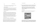
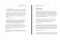
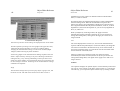
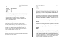
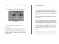
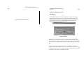
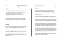
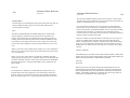
File Requester
If you've ever used an Amiga program that saves and/or loads files you
understand how Turbo Silver's file requester works. Below is an
illustration:
Mouse usage in Silver adheres to the Intuition standard used by many
Amiga programs. To access the drop-down menus, hold down the right
mouse button and move the pointer to the top of the screen. Use the left
mouse button to select and access frames when in the Animation Editor,
and to manipulate objects when in the Object Editor. Whenever this
manual uses the phrase 'click on' something, it means to position the
mouse cursor over the object and press the left button, then release it. On
the other hand, 'click and hold' means to keep the left mouse button
depressed, the way you keep the right mouse button pressed when you
navigate the menus.
Entering Numeric Data in Silver - Using the Requesters
Turbo Silver uses a lot of numbers-for color, position, rotation, size, and
many other settings. Most requesters let you use two or three different
methods for entering values: directly from the keyboard; by clicking and
holding on up/down value adjustment gadgets (they look like small
arrowheads) next to the number; or by clicking and dragging the value
slider left or right. When you hold the mouse button down on the
File Requester
Note that the bottom row (or rows) of gadgets in the file requester shows
all drives on line in your system. Also, the two leftmost buttons in the top
row labeled ROOT and PRNT are for maneuvering upward through disk
directories. Click on the ROOT button from within any subdirectory to
24
Getting Started
File Requester
return to the highest, or root level. PRNT stands for Parent; click on this
button to return to the subdirectory immediately above the current o
specified in the DRAWER line. In hard disk usage, this line can be blanl
even though you're currently viewing a subdirectory, in which case the
PRNT gadget has no effect The window above the drive buttons shows a
list of all files and directories in the current directory. Note that when
using the Open command, only Silver Script files and directories appear in
the file list, and the .SCR extenders don't appear. Click on any other
gadget to list files on that drive. If there are more files than can fit in the
window, use the slider to the window's right to scroll the others into view
(click on and slide the dark bar vertically, or click immediately above or
below it).
To see the files inside a directory, click on the directory name in the file
list window. You can also type in a path name after first clicking in the
box to the right of the word DRAWER above the text window. Once
you've found the name of your file click on it, then on the OK gadget to
the lower left of the window. If you're using the New command you'll
need to click on the box to the right of FILE and type in a new file name.
To escape the file command without changing anything simply click on
the Cancel gadget.
Reference
Overview
25
Reference Section
The 3D World of Turbo Silver - An Overview
We've got a slight problem to overcome here. You see, humans and
computers have absolutely no problem dealing with three- dimensional
worlds. Unfortunately, we've yet to develop effective 3D displays for our
computers, and so must command them using interfaces based on the flat
displays currently in use. Alas, it's most difficult to effectively represent
a 3D world on a 2D display, and to quickly show changes in the world or
display.
Turbo Silver's Object Editor uses a three-window display (one window at
a time) to show the scene you're working on from three different
angles—above, from the front, and from the right side. These in
combination with the wire-frame mode of display used gives you a
reasonable idea of where things are and how they're positioned. Among
the advantages of seeing only one view at a time are fewer confusing
details for you and less for the program to redraw when you change
something, resulting in faster and more responsive editing.
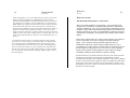
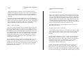
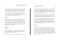
In Plane Geometry you learned about the X and Y axes of the Cartesian
Coordinate system which could be used in mathematics to make
two-dimensional graphs. In 3D computer graphics a third axis is added to
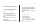
be able to describe an object's depth as well as its height and width. Each
point in the Turbo Silver 3D world can be referenced as a unique set of
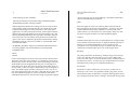
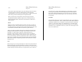
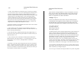
coordinates (X,Y,Z) on a three-axis Cartesian reference system. See the
illustration on the next page:
26
Reference
Reference
27
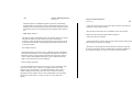
3D Axes
As an example and to help you start thinking in these terms, imagine an
object at coordinates 0,0,0 illuminated by a light source at -80,-90,100. In
this case the light source is eighty units to the left of the object, ninety
units in front of it, and 100 units above it.
In addition to describing objects' shape and location, the three- axis
system is used to describe rotational movement. Turbo Silver can rotate
groups, objects, faces and points in one-degree increments about any or all
of the three axes.
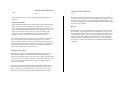
x,y,z axes showing +/-1000 extent
Thus the X coordinate describe's a points horizontal position, the Y
coordinate its depth or 'in-out' position, and the Z coordinate its vertical
position. Note that the center of the Turbo Silver 3D world is at 0,0,0, and
its extent is 1000 units in any direction. This means that all realistic
coordinates must fall in the range (-1000,-1000,-1000) to
(1000,1000,1000).
Each object in Silver (except the special sphere and surface objects-see
Edit Add Sphere and Edit Add Surface below) consists of a set of points
in space connected in triangular faces and/or edges. Objects can be
grouped, and you can manipulate groups, objects and sets of independent
objects, sets of points and faces in a variety of ways all described in detail
below.
Since Silver's wireframe editor lets you move groups, objects, points and
faces interactively, you won't often need to deal directly with location
coordinates. But should you need to use the Translate, Rotate, or Scale
commands, it's important to know the difference between local and world
axes. Every object in Silver has a small axis, or set of X, Y, and Z axes,
associated with it that's used as a control and orientation point. When an
object is first created, its axis is aligned with the Silver 'world' axis-that
is, as seen from the front X is left and right, Y is in and out and Z is up
and down. But when it's rotated it's no longer aligned, and you get
different results from performing the above transformations on a local or
world basis. Silver performs translation, rotation, and scaling in the
direction of any or all of the three axes. Transformations on the local
basis take place in the direction of the object or group's axis. On the other
hand, the world's axis never changes. This flexibility gives you complete
control performing transformations.
HINT: Since you can rotate, translate, and scale objects on their own
axes, you might want to change an object's axis on occasion. For
example, you can rotate an object on any of its vertices by positioning its
axis there. To do this, pick the object, activate Pick Face mode, pick any
face, Mark it, then click on the new location for the axis (you'll find
further explanation in the Reference Section below). Do this from all
three views for precise interactive placement of the axis. By the way, to
Reference
28 Light
perform actual transformations on objects' faces, you must use Point
mode, picking all the faces point by point.
Light in Turbo Silver's 3D World
Turbo Silver uses two types of light-point source and broad source.
Another name for broad source light is ambient, which means surrounding
on all sides. Ambient light doesn't come from anywhere in particular, but
illuminates all things evenly. Your only control over ambient light is its
overall level. As ambient light tends to 'wash' out images and can lead to
a bland look, we recommend minimal usage, especially since Silver
allows you as many as 32,000 point-source lights. You set ambient light
in the Global Settings requester.
Reference
The Camera
29
The Turbo Silver Camera
The camera (the small circle near the center of the window) is the only
object present when you enter the cell editor for a new cell. It's an object
like any other in the Turbo Silver 3D world, and the current scene is
always rendered from the camera's viewpoint. Of course the camera can
be positioned at any point in the 3D world, and can be aimed at any other
point. In addition, you can assign the camera position to paths to create a
moving vantage point during animations. Automatic tracking of any
object is a handy option but aim can also be set manually for special
effects. For realistic photograph-like results you can also set the camera's
focal length from extra-wide-angle to super-telephoto.
Using the Program
Any object in Silver can act as a point-source type of light, which has two
settings-As Sun or As Lamp. The latter is the more conventional setting
in that it illuminates objects in proportion to their distance from it-the
closer they are, the more brightly lit. The As Sun setting, however,
illuminates all objects with the same brightness no matter how distant or
close they are to the source. Also, the Shaded/Bright setting for light
sources determines whether or not it casts shadows. You can set any
point-source light's position as well as its brightness. In addition, you can
assign light positions to paths to create moving light sources during
animations. If you load an IFF brush onto an axis, then set it as a light
source, it projects the picture onto objects it illuminates!
Turbo Silver uses two modules-the Animation Editor and the Object
Editor. When you first begin using the program you're placed in the
Animation Editor, which resembles a film strip laid horizontally across
the screen. From here you can edit cells or groups of cells, access the
Object Editor for any cell, render cells' contents as still images, and create
animations.
Animation Concepts
To understand how to use Turbo Silver it's necessary to know the
difference between the terms cell and frame. A cell contains all the
information necessary to create a single frame in a Turbo Silver
animation. That is, a cell contains 3D objects and their attributes, IFF
brushes and stencils as well as global attributes for that frame. The term
frame in Silver usually refers to the final image rendered from a cell's
contents, plust that cell. The longest process in Turbo Silver involves
rendering a frame from a cell's contents. But once rendered, you can
Object Editor Reference
30 Getting Started
re-use a frame in an animation sequence as many times as you like
without
needing to render it again by simply replicating the frame.
Object Editor Reference
31
Introduction
Entering the Object Editor
Although the program begins in the Animation Editor, most interaction
takes place in the Object Editor. Whenever you load Turbo Silver, your
first action (after setting the graphic mode-see the Animation Editor
Reference introduction) should be to use the File menu to Load an
existing file or create a New one. Then, to enter the Object Editor for any
frame, just click twice on it. The first click selects the frame, turning its
text from orange to white (assuming default colors), and the second makes
a cell for that frame if one doesn't exist, then opens the Object Editor for
the cell. When this happens, Silver's Virtual File storage scheme creates a
slight pause while the cell's previous contents, if any, are loaded from
disk. Similarly, exiting the object editor saves the most recent results of
editing to disk automatically. Since most work is done in the Object
Editor, the manual discusses this section of the program first.
Object Editor;
Basic Operation
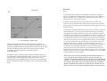
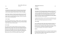
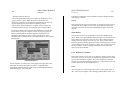
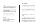
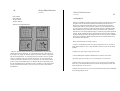
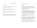
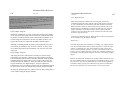
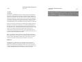
When you first enter the Object Editor in an empty cell, the screen looks
like this:
Object Editor Screen
32
Object Editor Reference
Object Editor Reference
33
General
General
The small circle near the center of the window is the can^andtite V'CW
is from the front, as noted in the information bar above the-ndow.
Options available here are many, starting with the ability tc ate
three-dimensional objects of just about any shape You can move mem
rotate and resize them, assign attributes such as color, reflectivity an,
transparency to parts or all of an object. You can also create amrnarion
sequences quickly and automatically. All these and more are expla
this section.
Picking and Selecting Objects
Objects normally appear in the window as white wireframe constructs on
a light blue background, each with its own small XYZ axis showing its
orientation. To perform operations such as translation, rotation, resizing,
and applying attributes such as color and reflectivity, you must first
choose the pertinent groups, objects, faces, or points in a process called
Picking, as in Pick menu. The default or startup Pick mode is
Group-click on an axis origin of a parent object to pick the associated
group. You can also pick child and independent objects in Group mode.
Once picked, objects and groups turn blue in color. At this point to
manipulate parts of an object you'd select Point or Face from the Pick
menu. To perform physical transformations on parts of objects use Pick
Point (Right Amiga-3). However, to apply attributes such as color,
transparency, and reflectivity to parts of objects, use Pick Face (Right
Amiga-4). The color red is used to indicate picked points or faces on an
object As a special case, to reposition an object's axis, use Pick Face and
pick any face, then use the Position command.
Once an object is picked (blue for objects, red for points) you can
reposition it interactively by clicking again on the axis (for objects) or
point. Or simply press the Fl function key. In any case the entire object
turns green. Click anywhere on the screen and the object or point is
repositioned there. This also works for multiple objects or points (see
Multi Mode below).
There is a fourth special color used for objects and groups-when first
placed, or selected via the Next command (see Special Menu below), they
turn orange, whereupon you can pick them by pressing the Fl key, which
turns them blue. Multi mode also works here-hold down the left Shift
key when pressing Fl and you can pick multiple objects. When using the
Next or similar command in Point mode points turn light blue and in Face
or Edge mode faces and edges turn green. Finally, objects clicked on
twice or picked, then activated with the Mark command (see Special
Menu below) turn green to indicate being ready for interactive
repositioning. At this point you need simply click on a new position in
the window and the object is repositioned automatically. For moving
parts of objects (Pick Point) or objects' axes (Pick Face), the entire object
turns green when you mark the points or faces, but only the points or axes
move when you perform the repositioning.
You can also use menu/keyboard commands to pick objects (Special
menu Home, Next, and Last commands and function key Fl), and you can
search for and select objects by names you give them (Special Menu Find
command). For further information consult the Object Editor reference
below. The other Pick modes are Object, Point, and Face. You can pick
any number of unconnected objects, points, or faces by holding down the
left Shift key as you click ('Multi' pick mode). You can then Mark them
for movement by continuing to hold down the left Shift key and clicking
on one of the picked (red) points. The entire object turns green, but only
the picked points (which remain red) move when you click on a new
location in the editor window.
NOTE: Certain faces in spun or extruded objects cannot be picked by
clicking on any of the associated points. In such a case you must use the
Right Amiga key in conjunction with the N, B, and H keys (for Next, Last
34
Object
Editor Reference
G
e
neral
Object Editor Reference
Edit Menu
35
Edit Menu
or Back, and Home, the first object added). In many cases you can
quickly and easily pick a 'stripe' of faces on a spun object with alternate
presses of Right Amiga-N (or B) and Left Shift-Fl.
Multi Mode
In any Pick mode, you can use the left Shift key to activate Multi mode,
shown at the top of the screen. If you continue holding down the left Shift
key as you click on objects, each turns blue (or red) in turn while all
others previously clicked on remain so. Then any transformation applies
to all picked. When several objects, faces, or points have been picked
using Multi mode, you can unpick each in reverse order of their original
selection with repeated presses of the F2 function key.
Color chart
Selected, ready to Pick:
Object, Group
Orange
Edge,Face
Green
Point
Light Blue
Picked, ready to Mark or transform:
Object, Group
Blue
Edge.Face, Point
Red
Marked, ready to move:
Object, Group,
Edge.Point, Face
Green (Group or entire object)
Note: you can change any or all of these color assignments as well as
various other Silver startup conditions. See Appendix A, "The Silver
Configuration File" for further information. Also, moving an edge or face
results only in movement of the axis.
This menu is used for basic object creation as well as standard editing
procedures. Most objects in Turbo Silver are composed of triangular
faces, but two of the shapes in the Add menu, sphere and surface, are 3D
unfaceted 'primitives' which render quickly. All other objects consist of
an axis (actually a set of small X,Y, and Z axes) and a set of connected
faces. These types of objects, called 'faceted', can be edited
point-by-point for physical remolding or face-by-face to change attributes
for different parts of an object. All Edit menu commands, as well as most
others in the editor can be reversed immediately after invocation by use of
the Undo command (Right Amiga-U).
Add SubMenu
This submenu lists commands used to add new objects, points and faces to
the editor workspace. Newly added objects are always located at 0,0,0,
the center of the workspace, and are colored orange. This means that you
can pick them by pressing function key Fl (they turn blue), then prepare
them for interactive repositioning by pressing Fl again or Right Amiga-M
(they turn green). Then click on the new location to perform the
repositioning.
IMPORTANT NOTE: Turbo Silver doesn't automatically place a light
source in the three-dimensional workspace, so make sure you do or else
your objects will be invisible. We recommend you make it a habit to add
and position an axis and set it to be a light source when first editing any
new cell. See Attributes in the Settings menu section below for details on
setting an object to be a light source.
36
Object Editor Reference
Object Editor Reference
Edit Menu
37
Edit Menu
Stencil
Automatic Name Requesters
Silver is set up to request names for all new objects created with Add
submenu commands. We recommend that you give all objects unique
names whenever using the Story or Track commands. After selecting the
type of object to add, the Rename requester appears. To easily delete the
existing default object name, press Right Amiga-X, or use the backspace
and Delete keys. Then type a new name in upper or lower case letters,
and press Retum-the name is converted to all upper case. Don't forget to
press Return, or the name won't be registered. You can rename existing
objects with the Attributes requester. You can disable the automatic
Rename feature by editing the SILVER.CFG file-see Appendix A.
There are a number of different types of objects in Turbo Silver:
Sphere
This 3D primitive is a perfect surface of revolution, which eliminates any
'faceted' appearance no matter how close the observer. Although you
can't manipulate individual points, all other standard Turbo Silver
transformations, including IFF brush wrapping, are available with the
sphere primitive. As the sphere primitive appears simply as a circle in the
Object Editor window, it helps keep the workspace uncluttered and
minimizes redraw time.
Incidentally, if you're familiar with the original (non-Turbo) Silver, the
Bounding object type no longer exists. Turbo Silver renders more quickly
without using bounding objects than previous versions of Silver rendered
with them.
A stencil is a special type of object in Turbo Silver-a drawing that
becomes solid! A stencil starts out as a one-bitplane (two-color) drawing
created in a paint program such as Impulse, Inc.'s new Diamond or
Deluxe Paint II. When rendered in Turbo Silver the background color
(usually black) is transparent while the foreground color behaves like a
standard Turbo Silver object. This means that you can apply such
attributes as color, transparency, and reflectivity-you can even load an
IFF brush onto the stencil! For further information refer to the section
describing the Stencils menu below.
Axis
The Add Axis command is the starting point for building a customized
object point-by-point and face-by-face. After adding and picking an axis,
you can add points and faces anywhere in the 3D space. You can also
spin a set of points and extrude a set of faces to make relatively complex
objects easily and with precision.
The default configuration file SILVER.CFG that comes on your program
disk provides you with an easy two-key alternative to the Add Axis menu
command. Just press and release the Esc key, then press and release
function key F2. You can set other Object Editor menu commands to the
function keys by editing the configuration file. See Appendix A for
details.
The object called Axis in Turbo Silver is actually a miniature set of X,Y,
and Z axes with a common origin, called the 'hot spot'. All objects
contain an axis. One method of picking objects for movement or setting
attributes is to click on the hot spot. The axis itself never appears in the
final rendered image.
Object Editor Reference
38
Object Editor Reference
39
Edit Menu
Edit Menu
The axis also acts as a control point for wrapping IFF brushes (images)
onto 3D objects. By loading a brush onto an axis, then grouping the axis
as a parent to an object, you can use the axis to control the image's size,
angle, and various other aspects in relation to the object by performing
transformations on the axis. For further explanation see the section on the
Brush menu below.
There are lots of other possible uses for the axis object-your imagination
is the only limit! Think of the axis as an invisible object that can have any
property available to Turbo Silver objects. For this reason the axis makes
an excellent light source. Or consider an example in which you wish to
show a group of objects orbiting a sphere. By simply grouping the set of
circling objects to the axis, with the axis as parent object, you can rotate
the group about the axis with one setting. Without the axis describing this
type of motion with a group of objects would be difficult at best. An axis
also serves well as a Track object (see Special menu) for an invisible point
of reference.
Custom
Selecting Custom from the Add submenu produces a movable requestor
displaying Turbo Silver's mini-library of built-in faceted shapes. Select
any of the six button gadgets for:
Sphere - a ball-shaped object
Torus - a donut shaped object
Cone - tapers up from a disk to a point, has no bottom
Tube - a hollow column
Extrude - an extruded disk, or solid column
Disk - a flat but solid circle
and the name of the object appears next to the words 'Choice is'. Then set
the dimensions by clicking in the corresponding box and typing in a new
value. All objects are created by spinning. The dimensions are as
follows:
Major Size — radius of sphere or torus, height of cone, tube, or extrude
(no effect on disk)
Minor Size — cross section of torus ring, or radius or one-half the X-axis
dimension of cone, tube, extrude, or disk (no effect on sphere)
Divisions — number of line segments in object's circumference (e.g. four
for square, five for pentagon, more for rounder objects-sphere always
doubles this number)
Keep in mind that the more divisions, the longer an object takes to render.
Object creation is always a compromise between good-looking objects
and time requirements.
Finally, click on the close gadget in the requester's upper left corner to
place the new shape at coordinates 0,0,0 in the editor workspace.
Once you've created a custom shape you can edit it point-by-point, resize
it, spin or extrude or build on it, or even split it! Read on to find out about
these and many other options.
Surface
This primitive (non-faceted) rectangle is provided so that you can include
a flat plane or wall in your animations without having to contract one.
Though you can't edit it point-by-point, you can resize it, load IFF
brushes onto it, and perform other standard Group and Attribute menu
operations with this object If you want a checkered ground, the easiest
way is to load the Chex texture (included with your program disk) onto
Object Editor Reference
40
Object Editor Reference
41
Edit Menu
Edit Menu
the surface, or you can load a checkered IFF image. You can use as ma
surfaces in a scene as you like.
Ground
(e.g. in the X and Z dimensions from the Front view), while the point's
position on the in/out axis (Y from Front view) is always 0. However,
with the Set Depth command from the View menu (see below) you can
position points anywhere in Silver's world without having to change
views.
The ground is a non-resizable horizontal surface that extends to the limits
of Silver's 3D universe. Grounds can be assigned attributes including
brushes and patterns, and they can be repositioned vertically ((
axis) only. You can use several grounds.
IMPORTANT: You can proceed directly from this command to Add
Edge or Add Face (see below) to further work on an object, but you must
return to Pick Object mode (Right Amiga-2) before selecting any other
command, otherwise you'll remain in Add Point mode.
Point (Right Amiga-6)
Edge (Right Amiga-7)
Use points to create paths for object motions or extrusions, or outlines for
spun objects, or creating objects from scratch. The basic procedure for
using Add Point is:
An edge is a line connecting two points. Edges are used in Silver
primarily for creating motion paths as well as spun and extruded object
outlines, rather than for creating objects from scratch.
• First place an axis (or other object)
• Pick it (so it turns dark blue)
• Add points
• Connect them with Add Edge (Right Amiga-7) or Add Face
(Right-Amiga-8)
All points placed before selecting a different command become part of
that object. After selecting Add Point click in the Object Editor window
anywhere you wish to place points. You can change the window to
different views during this process. You must add edges and/or faces for
the object to be useful.
NOTE: Normally when you add a new point to an object, you can only
position the cursor in the two dimensions permitted by the current view
First use Add Axis, then Add Point to add two or more points to the axis
(see above). Then after selecting Add Edge, click on each point to
connect in succession. A green line connects the last added edge, while
all others are green. You need click only once on each point in a path or
outline when connecting them with Add Edge. To connect points in a
nonlinear fashion, exit Add Edge (e.g. press Right Amiga-2 for Pick
Object), then return to Add Edge and start again at a new point.
NOTE: After adding edges to an object, you must return to Pick Object
mode (Right Amiga-2) before selecting another command such as Mold.
Face (Right Amiga-8)
After adding at least three points to an axis (see Add Point above) you can
connect them into triangular faces with this command. Before selecting
Add Face you must pick an Axis with at least three associated
42
Object Editor Reference
Edit Menu
points-when picked the Axis turns dark blue. Then, after selecting the
Add Face command, click on three different points in succession-you
needn't use Multi mode-to connect them with red lines, which show that
the new face is picked. Continue the process with groups of three points.
To quit, select Pick Object (Right Amiga-2).
Object Editor Reference
Edit Menu
43
groups or objects (but not points) to the workspace in the same place from
which they were cut. When you use the Cut command the previous
contents of the Paste buffer, if any, are erased.
Paste (Right Amiga-P)
Faces are useful for extruded objects with closed ends, or simply for
building objects from scratch. When building a closed end for an
extruded object, be sure not to leave any holes or unexpected results may
occur.
Makes a copy of the contents of the Paste buffer (see Copy and Cut
above) at the location from which they were cut or copied. Use repeatedly
to make multiple copies of an object or group.
All (Right Amiga-A)
A newly pasted group or object first appears as orange. This means you
can reposition it immediately with this simple procedure:
When editing points or faces in an object (see Pick Menu below) use this
command to pick all points or faces in the object. You can then unpick
particular points or faces by using the F2 function key in combination
with Next, Last and Home commmands in the Special menu.
Copy (Right Amiga-C)
The copy command places an identical copy of all picked groups or
objects in the Paste buffer, ready for duplication. Use the Paste command
below to clone copied groups or objects (but not points) back to the
workspace at the same place from which they were copied. When you use
the Copy command the previous contents of the Paste buffer, if any, are
erased.
Cut (Right Amiga-X)
This removes any picked group, objects, or points from the current Object
Editor workspace, copying groups and objects into an invisible Paste
buffer. Cut points aren't copied into the buffer, so any previously cut (or
copied) objects remain there. Use the Paste command below to restore cut
1. Press the Fl key to pick the object or group-it turns dark blue.
2. Press Fl again to 'mark' the object, making it ready for relocating-the
object turns green.
3. Position the mouse pointer in the window at the new location and click
the left mouse button—the object moves there.
If you're using the Story or Target commands we recommend renaming
pasted copies of objects with the Attributes requester to avoid confusing
the program.
Delete (Right Amiga-D)
Deletes any picked groups, objects, faces, or points. Use Undo to restore
the most recently deleted objects.
Erase (Right Amiga-E)
Erase is a quick way to clear the entire workspace, as it deletes all objects
and their properties whether picked or not. If used immediately after
44
Object Editor Reference
Edit Menu
Erase the Undo command can restore the contents of the editor
workspace intact. Erase does not alter Global settings (see Global s
requester below).
If you're in Pick Face or Pick Object mode, Erase deletes all picked
objects' faces or points. In the latter case only the axis remains, but in the
former all points remain, but no faces.
Object Editor Reference
Edit Menu
45
Then press Right Amiga-5 or select Edge from the Pick menu and pick a
line of connected edges that go complete around any part of the object.
Hold down the left Shift key (for Multi Mode) as you use the mouse or the
Next and Last commands (Right Amiga N and B) to pick the edges, which
turn red as they're picked. Then activate the Split command. If the object
can't be split, a requester appears. Try picking a different line of edges if
this happens.
Join (Right Amiga-J)
Group (Right Amiga-G)
You can join together any number of objects or points irreversibly using
this command. Pick all objects after any necessary alignment, then press
and hold the Right Amiga key while pressing the J key or select this Edit
menu item to join the objects. See the section above entitled Selecting
Objects for further details on picking multiple objects.
By grouping several objects you can apply single movement commands to
the entire group instead of having to issue separate instructions to each
object. This can simplify production of complex animations
tremendously. Grouping is also useful in the application of IFF image
files to Turbo Silver objects (see Brush Menu below). Grouping is also
useful in applying properties of one object to many (see Cluster).
Grouped objects can still be manipulated independently in Pick Object
mode (see Pick Menu).
The Join command is also useful for resolving multiple points, which
comes in particularly handy when importing 3D objects from programs
such as Sculpt 3D, VideoScape 3D, or Forms in Flight. Some of these
programs' Object Editors attach an unnecessarily large number of points
to a single intersection of triangular faces, which can increase Turbo
Silver's rendering time. In order to minimize rendering times use the Join
command to eliminate extra vertices in imported objects.
You can also use Join to 'weld' two separate objects into one, whether
they're touching or not. All points and faces are retained, and a single
axis remains at the heart of the first object picked. Remember-the Join
command is permanent. To combine objects temporarily, use the Group
command.
Split (Right Amiga-Z)
The Split command lets you divide a faceted object along a connected
circumference of edges. First pick the object to split so it turns blue.
To group two or more objects, use Multi mode (hold down the left Shift
key) to pick all objects starting with the parent object. The parent
object's axis is used to pick and manipulate the group. All subsequent
objects on which you shift-click are its direct children.
This relationship is shown graphically with purple lines when, after
picking the last child, you select the Group command from the Edit menu.
A line emanates from the parent to each child, and remains until they're
ungrouped. You can group other objects to parents or children of grouped
objects.
To manipulate a group, make sure you're in Pick Group mode, and click
on the parent object's axis to pick all objects in the group. You can
manipulate child objects independently while in Pick Group mode, and
46
Object Editor Reference
Object Editor Reference
Edit Menu
Special Menu
parent objects independently in Pick Object mode. To pass on attributes
(except Color, Reflect, and Filter) from a parent object to its children, use
the Cluster command (see Special menu).
UnGroup (Right Amiga-Y)
After picking a group, remove its objects' interdependence as well as their
chains (purple lines) with the Ungroup command.
Undo (Right Amiga-U)
The Undo command reverses the effects of the last command used. It's
one of Silver's most useful, and allows for fast experimentation as well as
human error.
Quit (Right Amiga-Q)
This is the same as clicking in the close gadget in the upper left corner of
the Turbo Silver Object Editor window. You're returned to the Animation
Editor in which the program starts.
Escape (Right Amiga-])
Use this command to exit a cell to the Animation Editor without retaining
any changes. The cell is not saved to disk, and if you re-enter the cell it's
exactly as it was before.
47
Special Menu
This menu contains an assortment of important commands. Presented
here are some of Turbo Silver's most useful functions-it'll pay you off in
time savings to learn their Hot Key equivalents as soon as possible.
Free (Right Amiga-F)
Use this command to free the camera from tracking an object or group.
See Track below for further details.
Track (Right Amiga-T)
Pick an object, then use the Track command to have the camera
automatically follow the object anywhere it's moved. You can also move
the camera and it will continue to track the object.
All objects in Turbo Silver 'contain' or are associated with a unique small
set of X,Y,Z axes. The origin of the axes is the 'hot spot' on which you
must click to pick the object. The Track command lets you set the camera
to always point directly towards the hot spot of an object or parent object
of a group. Then no matter where you move the object or group, the
camera follows it. This saves you the arduous work of manually aiming
the camera, and allows for such special effects as the classic cinematic
'fly-by' shot. To prevent automatic tracking use the Free command,
above.
The Track command affects and is affected by the Camera command.
Basically, an object must be tracked in order for the settings Wide Angle,
Normal, and Telephoto to take effect. See Camera settings requester in
the Settings menu below.
48
Object Editor Reference
Object Editor Reference
Special Menu
Special Menu
Apply (Right Amiga-)
Use Apply to transfer an object's attributes (see Attributes under Settings
menu, below) to one or more other objects. This command gives the
effect of the Cluster command without the necessity of grouping objects.
Use Multi mode to pick first the object whose attributes are to passed on,
then all objects to which the attributes are to be copied. That is, while
holding down the left Shift key first pick the object whose attributes are to
be transferred, then the others, then invoke the Apply command. This
works the same as Cluster, below, but doesn't require objects to be
grouped.
49
Home (Right Amiga-H)
Next (Right Amiga-N)
Last (Right Amiga-B)
Use these three commands to find specific objects in the order created.
They're useful for easing your way in a busy workspace. Home selects
and centers the first object created in the window, Next selects and centers
the object created immediately after the currently picked or selected object
if any, and Last selects and centers in reverse order of creation. Groups
and objects are turned orange when centered, faces and edges turn green,
and points turn light blue, ready for picking with Fl and Marking (see
below) and subsequent repositioning.
Cluster (Right Amiga-K)
This command lets you transfer a parent object's non-color-related
properties to all other members of its group. Pick the group by clicking
on the parent object in Pick Group mode, then set any attributes as
necessary, then select the Cluster command. The Cluster command
doesn't transfer the attributes Color, Reflectivity, and Filter.
Last uses Right Amiga-B as a mnemonic for 'back' or backwards. Use
the Next and Last (or Forward and Back) in conjunction with Left
Shift-Fl (multi-mode select) in Pick Face mode to quickly mark
contiguous faces for stripes of color or any other effect.
Find (Right Amiga-V)
When grouping objects the parent object is always the first chosen.
Objects needn't be of the same type-for instance, you can set the same
properties for a number of different shapes by grouping them to an axis
(which is invisible), then setting blending, specularity etc. only for the
axis. We suggest an axis because you can also use it as a center of
rotation for the group.
Use to quickly find an object or group by name. Invoking this command
after selecting an object displays a requester. Enter a unique name-any
combination of letters, numerals, and punctuation is allowed. If the name
is one that you or the program has given to an object or group, the object
appears selected in the center of the window. If there are more than one
object with the name searched for, the first one created is shown.
When wrapping a brush around an object (see Brush menu below) you
must load the brush onto an axis, group the axis to the object, and finally
Cluster the two.
Mark (Right Amiga-M)
Use this command after picking a group, object, or set of points to prepare
it for repositioning. The group or object turns green-click anywhere in
the screen to set the new location. In the case of points, even though the
Object Editor Reference
50
Special Menu
entire object turns green only the selected points are repositioned. Select
objects by clicking on the hot spots or with the Home, Next, Last, and
Find commands (see above). This also works with faces, only the axis is
repositioned instead of the face.
NOTE: An easy one-key alternative to this command is the Fl key, which
marks picked objects for moving.
Redraw (Right Amiga-R)
Invoking this command causes all objects to be redrawn on the screen in
their current position. This command is necessary as occasionally in the
heat of editing the program can forget to redraw an object.
Auto Redraw
Manual Redraw
Only one of these is active at a time. The program starts in Auto Redraw,
which means that all objects are redrawn whenever you change anything.
If you have a lot of objects on the screen and are only concerned with one
at the moment, turn on Manual Redraw to speed up the program. Other
objects may not appear properly after transformations when Manual
Redraw is on. Select the Redraw command (above) when in Manual
Redraw to see all objects.
Object Editor Reference
Settings Menu
51
Settings Menu
This menu contains all the commands for manipulating objects and the 3D
universe in which they're contained. Featured are the four full-screen
requesters; Global settings, Camera settings, Transformation, and
Attributes. Each of these allows you to make a number of varied
adjustments to existing settings at one time without having to invoke
several different menu items.
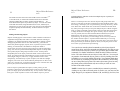
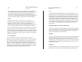
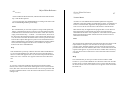
Global*
(Function Key F4)
The first Settings menu item controls aspects of the entire scene such as
ambient lighting, camera, sky characteristics, and heuristics which
controls objects' edges and surfaces. You can invoke the Global Settings
requester at any time with this menu item, or by pressing the F4 key. The
requester appears:
Hint: Another way to speed up redraw is to set complex objects to Quick
Redraw-see Attributes below.
Global Settings Requester
Exit the requester by clicking on its close gadget in the upper left comer,
whereupon all settings take effect. To return to conditions before
changing the Global settings, use the Undo command (Right Amiga-U)
52
Object Editor Reference
Object Editor Reference
Settings Menu
Settings Menu
53
before selecting any other command.
colors in between. You can set the dithering or smoothness of this effect
with the Global Blending setting below.
Following is a discussion of each of the settings available through the
Global Settings requester, from top to bottom:
Fade
With the uppermost Global Colors settings you can set a range of colors
from horizon to zenith, set the fog fade-out color, and set the color and
strength of ambient light. To set any of the above, click on the square
gadget next to its name in the upper left corner of the requester. Next the
gadgets in the upper right change to show the current setting, if any, with
the color depicted graphically in the large square. From left to right, for
each of the colors, you can click the mouse pointer on the number and
type in a new value, or adjust the value upward or downward by clicking
and holding on the up or down arrow gadgets, or click and drag on the
horizontal value sliders.
The Blending, Pertubance, Edge Level, and Resolve depth all have their
own settings gadgets, which work identically to those described
immediately above.
Select this gadget to set the color of the fog effect (activated with the
Fuzzy setting from the Camera settings requester—see below), activated
with the Global Focusing Fuzzy command. As with any other color
setting in Silver, you can set this to any of the Amiga's 4096 colors with
any of the red, green, and blue color value adjustment gadgets.
Ambient
Ambient lighting affects a scene's overall brightness-it's a reflected light
source that has no particular location. A degree of ambient light may be
necessary to avoid inky-black shadows, but too much can cause
washed-out scenes. The default setting is no ambient light. Use this
command to set ambient light color to any of the Amiga's 4096.
Blending
Zenith
Horizon
Click on either gadget to set the sky colors at the zenith or at the horizon.
When the Camera Aim X-axis setting is 0 or 180 degrees you're looking
at the horizon, which in the real world is what you're looking at when you
stand outside and look straight ahead. Rotate your view 90 degrees in
either direction on the X-axis and you're looking at the zenith, which, in
the real world, is where your finger is aimed when you point straight up or
down. The default settings are black, which gives no sky. You can set
any of the Amiga's 4096 colors for either or both with the red, green, and
blue value adjustment gadgets. If you set two different colors Silver
automatically blends the two into each other using an appropriate range of
This setting determines the amount by which the range of screen colors
overlap (by dithering) with each other if you've set two different sky
colors. The color range is set with the Global settings commands Horizon
and Zenith (see above). A setting of 0 gives solid banded colors and the
maximum setting of 255 gives a completely dithered sky .
Perturbance
Perturbance is used in animation to give the sky a variable look of
turbulence, as in a storm. The perturbance slider ranges from 0 to 255.
The perturbance effect is obtained by varying the dithering pattern for the
sky's shading from frame to frame, causing a semi-random moving effect.
Object Editor Reference
54
Settings Menu
As with all of Silver's features, we strongly encourage to experiment with
this effect as much as possible.
Object Editor Reference
Settings Menu
55
emanating from the camera pointing in the direction in which the it is
aimed. The unique camera settings in the Global menu Camera submenu
control a good deal about the final appearance of your Silver-generated
images.
Edge Level
Anti-aliasing is a computer-graphics technique for smoothing off blocky
edges ('jaggies') in a limited resolution environment such as the Amiga's
320-wide HAM mode used for ray tracing. The initial setting is 30 in a
range from 0 to 255. The higher edge level is set, the longer a scene takes
to render, but the smoother edges appear.
Select Camera from the Settings menu or press function key F5 to display
this requester:
Resolve Depth
When rendering glass objects in silver, ray-tracing times can be too long
to make experimentation convenient. To temporarily reduce these times
you can limit the extent of rays sent out by the tracer by lowering the
resolve depth. Bear in mind, however, that changing this value alters the
effective index of refraction of materials such as glass and crystal. This
slider's value ranges from 0 to 15, and starts out at the middle level of 8.
Genlock
When selected this sets the sky to background color so that any genlocked
video signal shows through. See your genlock unit's instructions for
further information.
Camera
(Function Key F5)
Use this Settings menu item to control Silver's camera, which is your
point of view in the 3D universe. The camera always appears as the small
circle to the left of center in the frame when you first enter the object
editor for any cell. When viewed from the side you can see a short line
Camera Settings Requester
Value-entry gadgets in the Camera Settings requester don't use sliders.
Adjust values by clicking on any box containing a number and editing the
entry, or by clicking and holding on the up or down arrow gadget next to
the number. If you hold longer than a few seconds, the rate of value
change accelerates.
Exit the requester by clicking on its close gadget in the upper left comer,
whereupon all settings take effect. To return to conditions before
changing the Camera settings, use the Undo command (Right Amiga-U)
before selecting any other command.
Following are the Camera settings available in the requester:
56
Object Editor Reference
Settings Menu
Position
Upon selecting the Camera Settings requester the first three settings show
the camera's current position on the X, Y, and Z axes, which is initially
-100,-100,100. You can position the camera anywhere in Silver's 3D
universe with the requester's Camera Position X, Y and Z- axis gadgets.
It's often easier, though, to position the camera interactively via the object
editor window. Click twice on the camera-it turns green-then click on
the new location. The camera disappears from its original location and is
redrawn where you clicked. Do this from all three views (see View Menu
below) for precise camera placement.
Camera Angle
One of the most important points to remember in Silver is always keep the
camera aimed at your focus of interest. An easy way to do this is with the
Track command (above under Special Menu). Or you can use the Camera
Angle settings to aim the camera precisely.
Focal Length
This setting only applies when the Manual lens setting is in effect (see
Lens Setting below). The focal length of the camera lens determines the
width of the camera's field of vision. The lower the number, the wider the
field of vision, and the higher, the narrower. The range settings use the
convention of 35mm camera lenses. For example, most cameras come
with a 50mm lens, which gives a narrower view than the standard human
field of vision, which is comparable to a 28mm lens. The Focusing
submenu (below) gives you several automatic settings for Range.
Object Editor Reference
Settings Menu
57
Fade Start
Fade Finish
When the Camera Settings Fuzzy option (see below) is in effect, the Fade
command lets you set a gradual fog fadeout special effect along the Y
(in-out) axis. The primary purpose for doing so is to avoid distracting the
viewer with unnecessary horizon details, an artifact of Silver's camera
lens' infinite depth of focus. The two adjustments let you to set the
position on the Y axis at which fog initially appears and at which total
fadout occurs-default settings are 100 and 1000 units. The fog gradually
thickens from the first to the second point.
To put the Fade into effect, you must select the box labeled Fuzzy in the
requester's lower right corner. Also, you can set the fog's color with the
Fade setting in the Global Settings requester (see above).
Lens Setting
The five gadgets in the upper right of the Camera Settings requester give
you several automatic camera range settings, as well as the ability to
temporarily override the manual range setting with the Custom setting.
Only one setting is available at a time-an X appears in the box to the left
of the active item. Lens settings are analagous to those used in
conventional photography, with exceptions as noted below.
Manual
This item, when selected, tells Silver to use the Focal Length setting from
the Camera Settings requester-see above for details. This works just like
a real camera lens-the higher the focal length, the closer the object
appears and the less distortion is visible.
58
Object Editor Reference
Object Editor Reference
Settings Menu
Settings Menu
Wide Angle
Normal
Telephoto
These three automatic range settings simulate three standard focal-length
lenses used on 35mm cameras: the 35mm wide angle lens; the 50mm
normal-length lens; and the 135mm telephoto lens. Object tracking (see
Special menu above) must be in effect for this to work. These mainly
control apparent distortion. To change the image size, move the camera
closer to or farther away from the subject.
Custom
The Custom setting lets you set an apparent size for objects in view
without regard to any range setting. The slider lets you set any value
between 0 and 2.55, the maximum size at which the camera appears to
practically on top of the object
Sharp
Fuzzy
Sharp, the default condition, means all objects within view of the Silver
camera lens are in detailed focus, including the horizon line if any. Since
the horizon line can sometimes be unnecessarily distracting, you can
create a detail-obscuring gradual fog at the horizon with the Fuzzy setting.
Use Fade Start/Fade Finish in the Camera Settings requester to set the
point at which fadeout starts and at which it's totally obscuring. Use Fade
in the Global Settings requester to set the fog's color. An X appears next
to the selected item-only one or the other can be set at one time.
Transformations
59
(Function Key F6)
The settings in this requester pertain to objects in the 3D universe. Unless
otherwise specified, the term 'objects' can refer to groups, single shapes,
or parts of shapes such as points, faces, and edges. Most manipulations
can apply to single objects as well as groups of objects selected with the
left Shift key held down, in 'Multi' mode. In order for Silver to know
which object you want to manipulate, you must first pick the object,
which can be done with the mouse, keyboard, or a combination of the two.
At any given time you can pick grouped objects, single objects, points,
edges, or faces. Pick Group mode is an exception-you can also pick
single objects in this mode. Picked objects and groups are blue, and
picked points and faces are red. In Silver, a 'selected' object appears
orange, selected points are violet, and selected faces and edges are green.
In any case, you pick a selected object by pressing the Fl function key.
You can pick multiple objects, groups, points, or faces by holding down
the left Shift key as you click on your choices. When you hold down the
left Shift key the word 'Multi' appears at the top of the screen to signify
that you're in Multi mode.
When you select multiple objects (rather than grouped objects) for
transformations, you're presented with the Transformations requester for
each object selected, in the order selected. That is, each time you close
the requester it reappears for the next object, until all objects are set.
NOTE: Transformations in this requester performed on picked faces or
edges affect only the object's axis. To translate or rotate faces, pick all
associated points in Point mode.
See the section entitled 'Picking and Selecting Objects' above for further
information.
Object Editor Reference
60
Settings Menu
Object Editor Reference
Settings Menu
61
straighten it up (or out). Align is an absolute rotation, whereas Rotate,
below, is a relative rotation.
First pick the object to be aligned, then press F6 or select Transformation
from the Settings menu. When the Transformations requester first
appears, the object's current alignment is displayed. To return an object
to its original orientation after any amount of rotation, set the X, Y, and Z
alignment to 0, then close the requester. Or you can set any alignment on
the X, Y, and Z axes.
When you adjust any of the align values, the Apply box below
automatically becomes selected (contains an X). To prevent the new
settings from taking effect, click again on the Apply box so that it's no
longer selected.
Transformations Requester
Note that any relevant current settings are displayed in the various fields.
Exit the requester by clicking on its close gadget in the upper left corner,
whereupon all settings take effect. To return to conditions before
changing the Transformation settings, use the Undo command (Right
Amiga-U) before selecting any other command.
Value-entry gadgets in the Transformations Settings requester don't use
sliders. Adjust values by clicking on any box containing a number and
editing the entry, or by clicking and holding on the up or down arrow
gadget next to the number. If you hold longer than a few seconds, the rate
of value change accelerates. Following are the Transformations settings
available in the requester:
Align
The first three settings allow you line up any object or group's axis, and
the object as well, with that of the 3D universe-in other words, to
Size
The values displayed next to Size X, Y, and Z in the Transformations
requester indicate the picked object's current size and lets you change the
size in Silver world units in the direction of any or all of the world X, Y
and Z axes in absolute terms. To resize faces pick the associated points
and use the Scale command, below.
When you adjust any of the align values, the Apply box below
automatically becomes selected (contains an X). To prevent the new
settings from taking effect, click again on the Apply box so that it's no
longer selected.
Position
The requester displays the picked object's current absolute position and
lets you set a new position in the Silver world via the X, Y, and Z axes.
Alternatively, you can position objects interactively by clicking on them
62
Object Editor Reference
Object Editor Reference
Settings Menu
Settings Menu
twice (at the origin of the object's axis), then clicking in the new location.
To change objects' location by relative amount, use the Translate
command below. To move any of an object's faces or edges, go into Pick
Point mode, pick the associated points and reposition them.
When you adjust any of the position values, the Apply box below
automatically becomes selected (contains an X). To prevent the new
settings from taking effect, click again on the Apply box so that it's no
longer selected.
Rotate
Rotation is always performed about the center of an object or group as
defined by its axis, and is a relative motion. You can reposition the axis
by picking the object, entering Pick Face mode and picking any face, then
use the Position command (menu or interactive) to place the axis.
When you change any Rotate setting, the box marked Local below the
settings becomes selected. Local rotation uses the object's own axis for
orientation. To rotate objects using the constant world axes for
orientation, select World by clicking in the box next the word World.
Remember, rotation about the X axis works like a spit or lathe, about the
Y axis is like turning a doorknob, and about the Z axis is like a spinning
barber pole. To rotate faces, go into Pick Point mode, pick the associated
points and rotate them, remembering that the center of rotation is always
the object's axis.
Scale
These settings let you resize picked objects in relative units rather than the
absolute units used in the Size command. In scaling an object the Scale
values are multiplied by the object's current size. That is, a Scale value of
1 means the object stays the same size, 3 triples the size, and .5 halves it.
63
To scale a face or group of faces belonging to a picked object, pick any
faces by going into Pick Point mode and picking all associated points,
then scale in the desired directions. You can scale on any or all of the
three axes with respect to the the object's own axis (Local) or the world
axis (World).
Translate
The Translate settings let you move picked objects units a given distance
from their current position—that is, a relative move rather than the Position
command's absolute move. Translation is described in Silver world units
via the X, Y, and Z axis settings. To translate faces, go into Pick Point
mode, pick the associated points and reposition them. You can perform
translation on any combination of the X, Y, and Z axes with respect to the
Local or the World axis.
64
Object Editor Reference
Object Editor Reference
Settings Menu
Settings Menu
Attributes (Function Key F7)
You can assign attributes such as color, reflectivity, transparency, etc., to
groups, objects, or faces. While the first three attributes-Color,
Reflectivity, and Filter-can be applied to individual faces as well as to
objects and groups, the rest can only be applied to groups or
objects-they're all specified below. A number of special effects are
available with these settings—the combinations are virtually endless!
As with the Transformations requester, described above, you must first
pick an object, group, set of objects, or faces. If you pick a group of
objects in Multi mode, the Attributes requester reappears for each
subsequent object when you close it. After picking objects, select
Attributes from the Settings menu or press function key F7. The requester
below appears:
65
Following is a description of each Attributes requester setting from left to
right and top to bottom:
Object
This field shows the object's current name. To rename the object, click in
the field and edit it to show the new name, pressing Return when done.
All lower case letters are converted automatically to upper case by the
program.
Quick Redraw
Click in the box next to Quick Redraw to activate this attribute for an
object. When active, Quick Redraw means the object is represented in the
Object Editor as a box with an axis. The box is three-dimensional and
roughly shows the object's size from any view, but no surface details.
However, the object always appears accurately in the Wireframe view and
when rendered. This greatly speeds up working with complex objects in
the Object Editor. All object editing commands work as usual with
objects set to Quick Redraw.
Color, Reflectivity, and Filter
Attributes Requester
Exit the requester by clicking on its close gadget in the upper left corner,
whereupon all settings take effect. To return to conditions before
changing the Attribute settings, use the Undo command (Right Amiga-U)
before selecting any other command.
These three settings use the same set of gadgets to display current values
and set new ones. To use any one, first click in the appropriate box in the
top left of the Attributes requester. The Color, Reflectivity and Filter
settings are not transferred among members of a group when you use the
Cluster command (see Special Menu above).
Color
You can apply any of the Amiga's 4096 colors to any group, object, or
face. This sets the brightest color-shading produces darker hues. First
66
Object Editor Reference
Object Editor Reference
Settings Menu
Settings Menu
click in the box next to Color, then use the mouse to control the Red,
Green, and Blue color settings via the up/down arrows and sliders, or click
on the number box and type in a new value between 0 and 255. The
current color is shown in a large square box in the requester after you
click on color. Note that for picked objects this is the object's basic color,
which doesn't reflect any faces you may have recolored individually.
Reflect
Reflectivity causes objects or faces to have mirror-like properties,
showing reflections of objects around them. This differs from a shiny
effect (like a cue ball), which you can set with a combination of
specularity, hardness, and Glossy, all of which are explained below. You
can set red, green and blue reflectivity individually between 0 and 255.
Some of Silver's most dramatic effects are available with this command.
Any group, object, or face in Silver's world can be set to reflect some or
all of the red, green, and blue light that comes its way. Thus for unusual
effects you could have, for example, a green object that reflects only red
light! Be careful about using the higher reflectance values-perfect
reflectors are invisible!
Notes on Reflectivity
We have found, after many hours of experimentation, that there is
definitely an art to using reflective objects in Silver's world. The problem
lies in situating the right sorts of things next to each other-you can't see
that an object is reflective unless there's something of the right color
nearby. For example, a gold sphere in a blue world or illuminated by blue
light doesn't look gold. But place it on table top behind a goblet, a pear,
and an apple, and it will look like a gold sphere. Use the Glossy setting to
create shiny-looking objects without requiring reflectivity.
67
Filter
The Filter settings determine transparency for selected objects or faces.
Just as any object can reflect light in any of the three additive colors (red,
blue and green), it can pass light through, or be transparent. What's more,
both properties can be combined in a single object. Select objects to be
adjusted, then activate this command. The red, green and blue sliders in
the requester that appear can be adjusted from 0 (pass no light) to 255
(pass all light, or completely transparent). Transparency can be combined
with refraction (see Material below) to simulate such materials as glass,
water, etc. Also, set red, green, and blue transparency to 255 for the
Glossy effect.
Blending, Roughness, Specular, and Hardness
These special properties can be applied only to selected objects or groups,
not specific faces. The requester has separate up/down arrow settings and
sliders for each property. You can also click on the box showing the
numeric value and edit it with the keyboard.
Blending
This lets you set the blending for any object between 0 and 255. Blending
determines the amount by which the range of an object's shading colors
overlap (by dithering) with each other. When blending is set to 0 on
shaded objects a solid banding effect occurs. For more realistic effects set
blending between 30 and 100. Set blending below 25 for objects to be
colored as IFF brushes.
Roughness
This command lets you set an apparent rough surface for objects in Silver.
Most objects in ray-traced scenes on the Amiga have a characteristic
68
Object Editor Reference
Settings Menu
smooth look because such objects are quickest to render. By increasing
this setting you can simulate such surfaces as wood, rough stone, etc. As
with all such settings experimentation will lead you to the most
satisfactory results. You can set roughness for any object between 0 and
255.
Specular
Specularity refers to the small white reflection of the light source on
brightly lit shiny objects. This setting, which ranges from 0 to 255, lets
you control the intensity of each object's specular spot-first select the
object, then select Properties from the Attribute menu and use the mouse
to set specularity.
Hardness
This value interacts with the Specular value above to control the
brightness of the specular spot. For example, a Specular value of 255 and
a Hard value of 15 gives the smallest, brightest spot possible, while lower
values of Hardness spreads it out and lower values of Specualr decreases
the intensity.
Material
Immediately to the right of the above property settings is a column of
settings that lets you determine an object's index of refraction. This
works only on selected objects (and groups), not parts of objects. The
requester always shows an X in the box next to the material setting for the
selected object. The Material command lets you set an object's index of
refraction, thus simulating different types of transparent substances such
as glass, crystal, etc. Of course, the effect is only visible if objects are
transparent (see Group Filter above).
Object Editor Reference
Settings Menu
69
Air
This is the default setting and is automatically assigned to all newly
created objects. When you set any degree of transparency for an object,
the Air material setting means that rays of light pass through it without
being refracted at all, as if the object were made of air.
Glass
Water
Crystal
Although you can assign any realistic index of refraction to any object in
Silver, we've given you three built-in settings for convenience. For
reference:
Substance
Glass
Crystal
Water
Index of Refraction
1.66
2.00
1.33
See Custom below for further information.
Custom
This setting lets you assign any index of refraction from 1.00 to 3.55 to
objects in Silver. Simply select the object, then select Attributes and enter
the new value into the requester with the mouse or keyboard. Here's a
sample table of indices of refraction for various substances:
Substance
Salt
Quartz
Emerald
Index of Refraction
1.54
1.55
1.57
70
Substance
Lapus Lazuli
Topaz
Ruby
Sapphire
Diamond
Object Editor Reference
Object Editor Reference
Edit Menu
Edit Menu
Index of Refraction
1.61
1.61
1.77
1.77
2.42
As a rule of thumb, the higher a substance's index of refraction, the longer
it takes to trace. To shorten tracing time for scenes containing refracts
objects, lower the Resolve setting (see Globals above).
For an authoritative list of indices of refraction, consult the CRC
Handbook of Chemistry and Physics, 63rd Edition, published by CRC
Press, Inc. of Boca Raton, Florida.
Unlit, As Sun, As Lamp, Intensity
These settings in the lower left corner of the Attributes requester
determine whether or not an object acts as a source of light, and if so, its
nature. Any object can be a light source, in which case the direction or
directions in which it casts light is determined by its shape and position.
A flat object casts light forward and backward (or up and down,
depending on its orientation), while spherical objects cast light in all
directions. Note that light sources themselves aren't visible in Silver's
world, so most other attributes don't apply to them.
Unlit
This is the default setting for all newly created or imported objects. Unlit
means the object doesn't act as a light source, but reflects and/or transmits
light, depending on its other attributes.
71
As Sun
As Lamp
Setting a selected object to As Sun causes it to illuminate all objects with
equal intensity disregarding distance from the light, just like ol' Sol. The
closer a Sun is to an object, the shorter the shadows and the brighter the
specular spot (see Specular under Properties in the Attributes Menu
section below).
To simulate a more earth-bound type of light, use As Lamp to illuminate
objects in inverse proportion to their distance from it. That is, of course,
the further the object, the less the illumination. Positioning a lamp very
far from objects results in little or no illumination.
Silver is limited to a maximum of 32,000 light sources in a single scene.
Intensity
With objects set to As Sun or As Lamp, this gadget lets you set the light's
strength. The initial setting is 300, and average value. We recommend
against extreme changes in light intensity- too much can cause glare, and
too little reduces object shading and visibility.
Shaded
Bright
You can set any object to shaded or bright, but not both. This setting's
effect depends on whether an object is set to Unlit or acts as a light source.
Newly created objects in Silver are set to Unlit and Shaded, which means
they're illuminated by light sources in a realistic way-the point closest to
a light is brightest while other sides fall off in brightness and become
progressively darker. Setting an unlit object to Bright causes all sides to
be illuminated the same, as if the object were itself a dim light source.
Bright objects don't illuminate other objects, though.
72
Object Editor Reference
Edit Menu
When you set an object to be a light source with As Sun or As Lamp, the
Bright setting is automatically selected. This means that no shadows are
cast by the light source. Click on Shaded to cause the light source to cast
shadows. Use of the Shaded option lengthens rendering time, as extra
calculations are required to draw the shadows. When using multiple light
sources we recommend setting no more than one or two to Shaded to
minimize rendering time.
Smooth
Facets
Newly created objects in Silver are set to smooth, but Facets is an
alternative setting which gives objects a 'blocky' look. Selecting Facets
turns off smoothing for a selected object. Large faces in Silver are usually
made up of a number of smaller triangular facets, a special technique
called Phong smoothing is applied to simulate a rounded surface. In some
cases such as with extruded 3D alphabet letters and symbols, you'd want
edges to appear sharp so set these to Facets.
Normal
Glossy
Object Editor Reference
Edit Menu
73
Texture menu to load a texture onto an object and set attributes. See the
section on the Texture menu below for detailed information on this
unique, open-ended option.
Coloring-Matte, IFF Brush, Genlock
These three alternative settings determine the nature of an object's allover
coloring. The default setting is Matte.
Matte
All newly created objects in Silver are automatically assigned this
Coloring setting, which means that the object is colored with whatever
color or colors you assign it with the Color setting at the top of the
Attributes menu.
IFF Brush
The Normal setting is assigned by default to all newly created objects.
The alternative Glossy setting lets you give non- reflective objects a shiny
appearance. For Glossy to take effect you must also set an object's Filter
settings for red, green, and blue to 255. Try combining Glossy with
Reflective to enhance the appearance of shininess.
This option sets an object to use an IFF Brush, or picture file, as coloring.
One of Silver's special features is the ability to apply pictures from paint
programs such as Deluxe Paint II and our own Diamond digitizing and
paint program around 'solid' objects in silver. To create a resizable IFF
brush, Add an Axis, set it to IFF Brush coloring via this menu item, then
load an IFF brush into it with the Brush menu. Also, IFF Brush objects
acting as light sources (As Sun or As Lamp) project their images onto
nearby surfaces. See Brush Menu below for details.
Texture
Genlock
Texture is an independent setting which can be combined with any other
combination of attributes. After setting an object to Texture, use the
Coloring an object as Genlock means that its entire surface is always
assigned the background color (usually black) so that any genlocked video
signal shows through. See your genlock unit's manual for details.
74
Object Editor Reference
Settings Menu
Skin
This command lets you custom-build complex objects from a number of
cross-sections. Although each cross-section can be any kind of object, in
practice it's best to use flat groups of points connected by edges (or faces,
if you want the cross-sections to be solid in the final object). The only
restriction is that all cross-sections must contain the same number of
points. Cross-sections can be oriented (rotated) any way with respect to
each other-thai is, they needn't be parallel-and they can be of any shape.
After creating and positioning all cross-sections, enter Pick Object mode,
pick all cross-sections while holding down the left Shift key
(Multi-mode), then select Skin from the Settings menu. After a few
moments, the cross-sections are connected together in a solid object. If its
shape isn't satisfactory, use the Undo command (Right Amiga-U) and try
again.
Here's a short tutorial which illustrates one of the many ways to use the
Skin command. As with any Silver command, don't be afraid to
experiment-you may be surprised and pleased with the results!
Object Editor Reference
Settings Menu
75
5. Use the Copy command from the Edit menu, or press Right Amiga- C.
6. Go to the Top view by pressing function key F10.
7. Press Fl to turn the picked cross-section green and ready it for
interactive repositioning. Now click on the screen an inch or so above
(behind) its original position and a half-inch to the side. The object
should disappear from its original position and reappear where you click.
8. Return to the Front view by pressing F9.
9. Now select Paste from the Edit menu or press Right Amiga-P to create
a copy of the cross-section on the screen in the same position from which
it was copied.
10. The original cross-section should still be blue to indicate that it's
picked. If not click on either cross-section so it turns blue.
11. Select Point from the Pick menu.
1. In a new Object Editor workspace (make sure you're in Front view
mode), use Add Axis from the Edit menu to begin creating a
cross-section.
12. Click twice on any point in the cross-section-the point turns red and
the cross-section turns green. Then click anywhere else on the screen to
reposition the point and connected edges.
2. Pick the axis (press Fl) and use Add Point from the Edit menu to add
five or so points to the axis in a roughly circular arrangement.
13. Repeat step 12 with one or two other points.
14. Return to Object mode from the Pick menu, or press Right Amiga-2.
3. Use Add Edge from the Edit menu to connect the points in a circle.
This is the first cross-section.
4. Enter Pick Object mode (press Right Amiga-2). Make sure the object is
picked and is colored blue.
15. One of the cross-sections should be picked (blue). Hold down the left
Shift key and click on the other cross-section's axis, so both cross-sections
are blue.
16. Select the Skin command from the Settings menu.
76
Object Editor Reference
Object Editor Reference
Settings Menu
Settings Menu
77
Extrude
17 After a few moments, the new object appears, with faces connecting
all points in the two original cross-sections. For a clearer view, u;
or Wireframe mode from the View menu.
The Extrude command is the Mold requester's default setting. This
function lets you create solid objects from two-dimensional outlines
composed of points, or any other shape. You can extrude in a straight line
along or along a three-dimensional path. You can also set the number of
sections for an extruded object. The Angle setting in the Mold requester
doesn't apply to extrusions.
Mold
Select this command from the Settings menu after picking an object to
invoke the Mold requester. The Mold command lets you create new
objects by extruding or spinning objects or outlines in various ways, all
detailed immediately below. In most cases, best results with Mold
functions are obtained with outlines composed of points and edges.
Here's the basic procedure for creating a shape from points and edges,
then extruding it:
• Use the Add Axis command to place an Axis object in the workspace.
The Mold requester looks like this:
• Make sure Front View is activated from the View menu.
• Use Add Point to add several points to the axis in an outline of the shape
to extrude. You can add points anywhere in the window.
• Use Add Edge and/or Add Face to connect the points in the shape of the
desired outline. If a flat object with faces is extruded, each section will
have the same faces on both ends, but if you extrude an object consisting
only of points and edges, the ends will be open.
HINT: You needn't connect a set of points to be extruded in one
continuous line. If you're adding edges, to start a new line of edges press
Right Amiga-2 (Pick Object), then re-enter the Add Edge mode (Right
Amiga-7) and start with a new point.
Mold Requester
This requester gives you two methods of creating custom objects;
extruding and spinning/sweeping. The Length setting applies only to
extrusions, while the Angle and Open/Close settings apply only to
swept/spun objects. The Number of Sections setting affects both extruded
and swept/spun objects.
|^
• To extrude along a path first create the path, then assign the object to be
extruded to the path. See Story below for detailed information on using
paths.
78
Object Editor Reference
Object Editor Reference
Settings Menu
Settings Menu
79
. Activate the Mold requester from the Setting* menu and set the numb
of units to extrude-the depth of the extrusion-and the "umber of sec
To extrude along a path, click on the box labeled By Story, and b
first assign a path to the object. Close this requester to perfo
extrusion.
• If the results are unsatisfactory, use the Undo command (Right
Amiga-U), pick the object or create a new one to extrude, and repeat ti
process.
Extrusion by length is always performed along the Y (in-out) axis. For
each section Silver makes a copy of the object a small distance from the
original with lines connecting every vertex.
letter M divided into triangles
5. Go into Pick Object mode (Right Amiga-2).
Extrusion Example
6. Select Mold from the Settings menu.
Step-by-step instructions for making a sample extruded letter M follow:
1.Use the Edit Menu Add Axis command to add an axis to the workspace.
7. The Mold requester appears showing the object's name in the title bar.
Extrude style is set to By Length, and the length is set to 100. This is the
length along the Y axis, or the depth.
2. The axis should be orange. Pick it (press Fl)-it turns blue.
3. Go into Add Point (Right Amiga-3) mode and add points to outline a
capital letter M as indicated below. Make the letter fairly large, filling
about a third of the screen.
4. Select Add Face from the Edit menu (Right Amiga-6) and connect all
the points into triangles by clicking on each set of three points to join in
turn. You can use your own scheme or follow the example on the next
page:
8. Click on the box labeled Number of Sections, which contains the
number 12. Edit this to 1 with the keyboard and press Return.
9. Click on the close gadget in the Mold requester's upper left corner to
extrude the M outline.
10. The unit is extruded. To see its depth, select Top View from the View
menu. Then return to the Front view.
It's that simple to extrude a solid letter M. If we'd wanted a hollow one,
with no front and back, we'd have connected the dots in an outline of an M
with Add Edge, and extruded that.
80
Object Editor Reference
Settings Menu
Sweep
Spin
These powerful commands let you create solid objects seemingly spun on
a lathe. While any object can be swept or spun, best results are obtained
with flat outlines created from points and edges. Objects are always spun
on the Z or vertical axis, and use the object's axis as the line of symmetry.
Therefore, it's usually a good idea to perform Sweep/Spin operations
while the Front view is active. The difference between Sweep and Spin is
that while Sweep spins all points, in Spin the first and last points act as
anchors and are not swept about the axis. Thus for fully symmetrical
objects you should always use Sweep.
Mold requester settings that affect Sweep and Spin are Angle, Number of
Sections, and if the angle is less than 360 degrees, Open/Closed. Angle
sets the number of degrees by which an object is spun about its axis (e.g.
180 degrees spins it halfway). Number of Sections sets the number of
divisions around the object's circumference-the more sections, the
smoother the object's outline appears when rendered, but the more
memory is required. For objects spun less than 360 degrees, Open/Closed
determines whether triangular facets are created on the unspun faces of the
object.
Here's the basic procedure for using the Sweep/Spin functions from the
Mold requester:
• From the Front view, use Add Axis
• Use Add Point to set a number of points in the object's profile
• Connect the points with Add Edge
• Select Pick Object (Right Amiga-2), then the Mold command
Object Editor Reference
Settings Menu
81
• Set the number of sections and number of degrees to spin, and if the
latter is less than 360 degrees, select Closed if you want the object to
appear solid from all sides, or Open for a hollow appearance. You should
make sure the first and last points set (and connect) are vertically aligned,
or have the same X coordinate (use the Coords On command in the View
menu) for true left-right symmetry.
• Finally, click on Sweep or Spin, then close the Mold requester by
clicking in the close gadget in the upper left comer of the requester to
perform the spin. If the results are unacceptable, use the Undo command
(Right Amiga-U) to retry. Remember the distinction between Sweep and
Spin—Sweep spins all points in the object, while Spin spins all but the first
and last points in the object.
Story
Story is one of the most powerful commands in Silver. It lets you perform
'path' and hierarchical animation, as well as set a path for extruding
objects. You can also use Story to rotate and/or scale objects during an
animation.
In path animation you first create motion paths by connecting strings of
points with edges, then assign one or more objects to it with the Story
command. You then use the Animation editor to assign the animation to a
number of frames to determine its length. The number of frames need not
match the number of points in the path; Silver interpolates smoothly in
any case. You can also use the Story command to assign objects to other
objects which are assigned to paths, thus creating hierarchical motion. An
example of this is the whirling rotor on a forward-moving helicopter. You
would simply assign the chopper to a path indicating direction, then set
the rotor to follow the chopper object and rotate so many degrees per
frame with the Relative setting.
82
Object Editor Reference
Settings Menu
Object Editor Reference
Settings Menu
83
Rotation
After picking an object to be animated (the object should be blue), select
£Sry command from the Settings menu. This requester appears.
As part of an object's story-that is, the animation to be performed-you
can set the object to rotate around its axis with respect to the local or
world X, Y, and/or Z axes. The Abs setting stands for Absolute rotation,
in which the object rotates the number of degrees set in the requester over
the course of the entire animation. In other words, if an object rotates 360
degrees with Abs set over a ten-frame animation, it rotates 36 degrees per
frame.
On the other hand, the Rel setting indicates relative rotation. That is, the
object rotates the indicated amount per animation frame, no matter how
long the animation.
Scaling
Story Requester
Note that the object's name appears at the top of the requester next to
"Story:".
Following is a discussion of each item in the Story requester:
Follow Path
To assign an object to a path, along which it will move during an
animation or for an extrusion by path, enter the name of the path in this
field in the object's Story requester. Remember, a path must consist of a
set of points connected linearly by edges, and must have a unique name.
Or, if you enter the name of another object here, the first object will
follow the second object (the one named in its story) wherever it moves
during the animation.
Setting a scaling amount other than 1.000 for any combination of axes
causes the object to change size steadily over the course of the animation.
As in Transformations scaling, objects can be scaled with respect to its
own or the world orientation. And as with Story rotation, the Abs
(absolute) setting causes the set transformation to occur over the entire
course of the animation, and the Rel (relative) setting causes the settings
to be applied repeatedly in each frame. For example, an X Scaling
amount of 2 applied relatively with the World setting would cause the
object to double in width (as viewed from the front) in each frame of the
animation.
Align to Y
This applies to path animation as well as extrusion by story (see Mold
above). It's useful for paths that aren't horizontal when viewed from the
front or side. When this function is turned on, objects align their Y
(in/out) axis to the path direction at every point on the path, rotating to
Object Editor Reference
84
Settings Menu
maintain a consistent orientation with respect to the path direction,
particularly useful with path extrusion for maintaining constant thickness
of the extruded object. It's also useful for depicting animation of objects
that continually turn to point in the direction they're moving, such as
missiles and airplanes.
Follow Me
An object set to follow a path with the Follow Me setting active causes
any objects grouped to that object ('child' objects) to follow the same path
in subsequent frames. A common example would be locomotive engine
pulling several train cars behind it. But in Silver you can make the train
(or any other group of objects) move along a spiral (or any other) path!
Here's a step-by-step example for using Follow Me:
1. Create a new file and double click on Frame 000 to enter the Key Cell
object editor.
2. Create a path: use Add Axis, then add several points, then connect them
in a line with edges. Use the Attributes requester to give it an appropriate
name (such as 'Path'). For more detailed information on creating a path,
see 'More about Story' directly below.
3. Now create the object that's to 'pull' the other objects- we'll call it
Engine. Use any simple shape, such as the Cone from the Edit menu Add
Custom requester.
4. Pick the engine, then activate the Story requester by selecting Story
from the Settings menu. Type Path (or the name of the path object) in the
space in the requester next to 'Follow Path'. Click in the box next to
'Follow Me' so an X appears in it, then close the requester.
Object Editor Reference
Settings Menu
85
5. Now create a few other simple objects and group them to the Engine
object. To do so, pick all the objects (so they turn blue) while holding
down the left shift key, starting with the Engine. Then select the Group
command from the Edit menu or press Right Amiga- G.
6. Now exit the object editor to the animation editor, and set up an
animation. While holding down the left Shift key, click once on Frames 1
through 8. Next invoke the Make command from the Cells menu. Click
on Frame 000 to select it, then select Source from the Cells menu. Next
select Use Story from the Cells menu, then All from the Edit menu. Then
select Target from the Cells menu, and Wire Frame from the Options
submenu in the Display menu. Finally, use All again, then Make Scene
from the Scene menu.
7. The animation should take no more than a minute or so to render. To
view your wireframe test animation, use Load Scene from the Scene
menu, then Play Scene (Once or Loop).
Drop Story
To prevent an object from being assigned to a path or another object
during an animation, pick the object, select the Story command, and click
on Drop Story. The requester automatically closes.
More About Story
Although the Story command is in the object editor, use of it requires that
you understand the Animation Editor Reference section of this manual.
Here's the basic procedure for performing Story animation in Silver:
• Create a new file and double click on Frame 000, which is the Key Cell
in the center of the lower half of the screen. This places you in the Object
Editor for the Key Cell.
86
Object Editor Reference
Settings Menu
Object Editor Reference
Settings Menu
• Create a path by adding an axis (name it Path or somesuch when the
Rename prompt appears), picking it by pressing Fl, then adding several
points along a path that an object is to follow. The more points you add,
the more detailed the movement. You can add points anywhere in
Silver's world from any view, changing the placement on the in/out axis
with the Set Depth command in the View menu.
• Connect the points with the Add Edge command to create a continuous
path.
• Pick or create (then pick) an object to follow the path.
• Select the Story command from the Settings menu.
87
• Now select all the frames over which the animation is to occur with the
All command-press Right Amiga-A.
• Select the Target command from the Cells menu or press Right
Amiga-T. This tells Silver to apply the story to all the Target cells. The
disk drive is busy for a few seconds, then the pointer reappears.
• At this point it's a good idea to go into several or all cells to make sure
the animation is working properly. Each cell's workspace should reflect
its point along the animation sequence.
• For a quick run-through of the animation, choose Wireframe from
Options submenu of the Display menu.
• When the Story requester appears, type the name of the path you entered
in step 1 in the box labeled Follow Path. Also enter any rotation or
scaling information. Click on the requester's close box to set the story.
• Select the loop point cell (usually #1) and select the Loop Point
command from the Scene menu.
• Now exit the cell by clicking on the close gadget in the upper left corner.
• Select all cells in the animation (Right Amiga-A for all).
• Determine the number of frames the animation is to take. If the required
number of cells isn't present, use the Make command on them. The Key
Cell is never included in the animation. If necessary, select empty frames
and use the Make command (using the left Shift key lets you select
multiple frames). As a guide, at full speed Silver displays 15 frames per
second.
• Select Make Scene from the Scene menu.
• Select the Use Story item from the Cells menu (unless the item is already
checked in the menu).
If you followed the above tutorial about using the Story command, you
know that the actual animation is created when you use the Target
command (with Use Story activated) to create a sequence of cells each of
whose objects is slightly changed from the previous frame. Of course,
you can set up a number of different animations at one time in a cell, but
normally they all take place over the same number of cells (that is, those
cells you select before using the Target command). If you want to create
• Select Frame 000, the Key Cell, and select the Source command from
the Cell menu or press Right Amiga-S.
• When the mouse pointer turns back from 'Busy' to the arrow, you can
load and view the scene with Scene menu commands.
Animation Hints
88
Object Editor Reference
Settings Menu
Object Editor Reference
Settings Menu
animation sequences of different lengths in one Scene, use the Merge
command. After using the Source/Target commands the first time, clear
the Key Frame of all objects, then create the new Story sequence, then use
Source/Join. This serves to combine the new animation with an existing
one.
• Pick the object and use the Save command to store it in a disk file.
Load (Right Amiga-L)
• Delete the object from the Object Editor workspace.
This Settings menu command activates a File Selector that lets you choose
the name of a disk file contain objects or groups to load into the
workspace. When loaded objects appear orange-to move them, press Fl
to Pick them, then Fl again or Right Amiga-M to Mark them, then click
on the new location.
Save (Right Amiga-S)
After picking objects or groups to save to a disk file, use this command to
activate the File Requester. Use the techniques outlined above in the File
Requester section to set the path and name the file, and click on Okay to
save it. Objects from different animations can be combined with each
other by use of the Save and Load commands.
external (Right Amiga-X)
Use this command to force Silver to store only one copy of an object with
saved cells on disk. This is useful for saving disk space when using
complex objects in animations. As explained elsewhere, Silver uses a
virtual storage system which causes each cell's contents to be stored
separately on disk. Complex objects cause cell data files to be quite large,
and using the same object in a series of cells can use up disk space
quickly.
89
it into each cell in which it's to be used. Here's the basic procedure for
making an existing object external:
• Select the external command
• The file requester to load an object appears. Select the object file for the
external object, whereupon it's loaded.
• From then on the program uses the external file to store that object for
all cells into which the object is loaded with the external command. If
you change the object, you must save it again to the external file.
90
Object Editor Reference
Brush Menu
Object Editor Reference
Brush Menu
Brush Menu
This command, one Silver's most powerful, lets you apply any IFF
bit-mapped image, including high-resolution and HAM, to any object.
The image, called a brush, can be either laid flat or wrapped around the
object's contours. This is sometimes called as texture mapping, although
in Silver a texture is a special case (see Texture Menu below). Judicious
usage of IFF brush wrapping can lead to some truly spectacular results.
You can have up to eight IFF brushes per cell. In animations, if you have
enough disk storage, you can use eight different brushes per cell, giving
you the possibility of having eight 'movies' playing inside your 3D
animation! In addition, you can assign IFF brushes to light sources,
letting them act as slide projectors.
91
the object as you want the image to be.
• Use the Load command from the brush menu to assign an image to the
axis.
• Group the axis to the object to be wrapped, with the axis as parent. In
positioning the axis in relation to the object it's important to remember
that the image is loaded onto upper right quadrant of the plane defined by
the axis' X and Z axes, that is with its lower left corner at the source as
shown below: -
One way to conceptualize 3D brush mapping is to think of a flag wrapped
around a large inflated beach ball. Silver can do this with any flat image
and any shape, and automatically takes care of the folds, wrinkles, and
loose comers.
To wrap an IFF brush around an object, load it into an axis which is
defined as a brush in the Attribute menu, set the wrap, resize it, then
Group it and Cluster it to the destination object. Here's a step-by-step
basic procedure-refer to the command reference below for details.
• Create the object that the brush is to wrapped around.
• Use the Edit menu to add an axis to the workspace.
Make sure to place the axis in this physical relationship to your object or
the image may not wrap properly.
• After grouping the axis as parent to the object to be wrapped, make sure
the group is picked and use the Cluster command (Right Amiga-K).
• Pick the axis (so it turns blue).
• Set the axis to Brush coloring with the Attributes requester.
• Resize the X and Z dimensions of the axis so it's as large in relation to
• Use the Wrap command to set whether the image will lie flat or follow
the object's contours.
92
Object Editor Reference
Brush Menu
Object Editor Reference
Brush Menu
93
Hints for Image Wrapping
It's usually a good idea, at least when initially experimenting, to make
your brushes (axis) slightly larger than the surface area of the object to be
wrapped. Also be careful in placing the axis with respect to the object-as
in dropping a cloth over a table, if you're too far to one side part of the
table is left bare.
IMPORTANT NOTE: Make sure not to set blending above about 25 for
objects wrapped with IFF brushes, or else the images will mush together
and be unrecognizable. For details see Blending under Attribute Menu
above.
IFF Brush Objects as Light Sources
An object which is set to both As Sun or As Lamp and IFF Brush in its
Attributes settings can act as a slide projector, beaming its image onto
nearby objects. Just as an object's shape determines how it casts light, the
shape determines the direction in which the image is cast. In the case of a
sphere, the image is cast in all directions about the object. The only object
that can't project an IFF Brush is the special Surface object in the Edit
Add submenu.
Note: For IFF Brush/light source objects you needn't load the brush onto
an axis first-simply load the brush directly onto the object.
Load
This command lets you use a file requester to assign an IFF picture file
name to a picked object (usually an axis) as well as to one of the eight
slots under Loaded Brushes at the bottom of the Brush menu. These slots
start out empty, each with the entry '-Unused-'. To load a brush, follow
this procedure:
• Set an object, usually an object, to Brush coloring via the Attributes
requester. Make sure the object is picked.
• Select one of the brush slots so that a check mark appears next to it.
• Then select Load from the Brush menu.
• Select a picture file name from the requester to place it in the checked
brush slot under Loaded Brushes. Note that this command doesn't
actually load the brush; that doesn't happen until the scene is rendered.
To inspect a brush use the View command below.
Drop
This command lets you free up a Brush menu slot under Loaded Brushes
so you can load a different one. Select the brush slot so a check mark
appears next to it, then select Drop from the Brush menu. The word
'—Unused—' now appears where the brush file name was.
View
To view any picture file loaded into the Brush menu under Loaded
Brushes, select it first so that a check mark appears next to it, then select
View from the Brush menu. The screen goes black and the file is loaded
and shown. Click the mouse's left button to return to the editing screen.
Wrap Submenu
This submenu gives you four choices-Flat X, Wrap X, Flat Z, Wrap Z-of
which only two can be active at a time. There are four ways of wrapping
a flat image around a three-dimensional object, derived from the four
combinations available in this submenu:
94
Object Editor Reference
Brush Menu
Object Editor Reference
Stencil Menu
Flat X Flat Z
Flat X Wrap Z
Wrap X Flat Z
Wrap X Wrap Z
These four are depicted below:
95
Stencil Menu
Stencils are similar to brushes in that they originate outside Silver in paint
programs such as Impulse's Diamond and Deluxe Paint II. However,
they're not wrapped around other objects, but loaded as free-standing
solid shapes in Silver. Stencils don't contain any color themselves, but
you can apply any of Silver's object attributes to them, including loading
IFF brushes onto them. The main restriction with Stencils is that they
must be two-color (one bitplane) images, containing only palette positions
0 and 1. When loaded into Silver, the background color in these images
becomes transparent while the foreground color is able to take on standard
Silver object attributes. While stencils don't have actual thickness, they
are solid and cast shadows.
Here's the method for creating a stencil:
• Create a one-bitplane picture in a paint program and save it to disk. If
using Deluxe Paint II, set it to any resolution with two colors at the initial
prompt.
The axis into which the brush is loaded should always be positioned
slightly below and to the front, as viewed from the front, of the object to
be wrapped. To apply the brush as flatly as possible without wrapping at
all, select Flat X Flat Z. To wrap the brush as around a vertical cylinder
such as a standing Coke can, use Flat X Wrap Z. To wrap the brush as
around a horizontal cylinder such as a lying Coke can, use Wrap X Flat Z.
And to wrap in both dimensions, use Wrap X Wrap Z. Naturally you're
free to experiment here as elsewhere, and it's actually in your best interest
to play around with brushes as even we haven't yet discovered all the
possibilities!
• Start Silver, open a file, and go into any cell.
• Use the Edit menu command Add Stencil to create a new stencil.
• Pick the stencil by clicking on it or pressing Fl so it turns blue.
• Stencils start out lying flat. To turn it so you can easily see it from the
front view, select Rotate World Axes from the Group (Object) menu and
rotate 90 degrees on the X axis.
• Set the stencil to the size you want with the Size and/or Scale commands
in the Group/Object menu.
Object Editor Reference
96
Stencil Menu
Object Editor Reference
Texture Menu
• Select Load from the Stencil menu, and select the name of the file from
step 1 with the file requester.
• You can now apply any standard attribute or resizing to the stencil. The
file is loaded during rendering of the image.
Load
This command lets you use a file requester to assign an IFF picture file
name to a picked stencil object as well as to one of the eight slots under
Loaded Stencils at the bottom of the Stencil menu. These slots start out
empty, each with the entry '—Unused—'. To load a stencil, select one of
the stencil slots from the Stencil menu so that a check mark appears next
to it, then select Load from the Stencil menu. Choose a picture file name
from the file requester that appears to place it in the checked stencil slot
under Loaded Stencils. Note that this command doesn't actually load the
stencil; that doesn't happen until the scene is rendered. To inspect a
stencil use the View command below.
Drop
This command lets you free up a Stencil menu slot under Loaded Stencils
so you can load a different one. Select the stencil slot from the Stencil
menu so a check mark appears next to it, then select Drop from the Stencil
menu. The word '--Unused-' now appears where the stencil file name
was.
View
To view any picture file loaded into the Stencil menu under Loaded
Stencils, select it first so that a check mark appears next to it in the Stencil
menu, then select View from the Stencil menu. The screen goes black and
the file is loaded and shown. Click the mouse's left button to return to the
editing screen.
97
Texture Menu
A texture is a user-defined and user-alterable pattern that is applied
uniformly to the entire surface of a solid object in Silver. An example of a
texture is a checkerboard, supplied on the program disk in a file called
Chex. You can set the size and color of the checkers with this menu.
Other textures may be supplied on the program disk. You can find out
more about them by loading them onto objects and using the Info
command from this menu. Also, Impulse Inc. will release into the public
domain the information and/or software necessary for Silver users to
create their own textures.
Load
This Texture menu command lets you load texture files onto objects in the
Object Editor workspace. You must first set the object to Texture
coloring via the Attributes requester, and of course the object must be
picked. Select the Load command, then select a texture file from the file
requester that appears. If you move the file to another disk or directory
you may need to move texture files as well, and reselect them with this
command.
Drop
This command lets you free up a Texture menu slot under Loaded
Textures so you can load a different one. Select the texture slot from the
Texture menu so a check mark appears next to it, then select Drop from
the Texture menu. The word '-Unused-' now appears where the texture
file name was.
98
Object Editor Reference
Texture Menu
Object Editor Reference
Pick Menu
Info
This command shows the parameters necessary for the texture to function
properly. Set the parameters with the Parameters command, below. Pick
the textured item before choosing the Info command.
Parameters
The Parameters requester contains a number of numeric entry fields for
entering the information specified in the Info command for a texture. Pick
an object that's been set to Texture coloring via the Attributes requester,
and has had a texture loaded, and enter the required information in the
first column, then in the second if necessary.
For example, the sample Checks checkerboard texture supplied on the
program disk requires four parameters; size and RGB values for the
checker pattern, which you should enter in the first four fields in the left
column of the Parameters requuester. The size should be a multiple of 32
(e.g. 64,128, etc.) and the RGB values should be between 0 and 255 in
the order red, green, blue. The other checker color is taken from the
textured object's original coloring.
99
Pick Menu
Use this menu to set the current Pick mode. If nothing is picked you can
pick only groups and objects which turn blue when picked. Once you've
picked an object, you can activate Pick Point, Edge, or Face to pick parts
of the object for changing shape or setting attributes.
There are a number of ways of picking objects, as outlined in the section
'Selecting Objects' above. To reiterate slightly here, the easiest way to
pick an object is to click the mouse pointer on its 'hot spot', or axis center.
You can pick multiple groups, objects, points, or faces by holding down
the left Shift key, which causes the message 'Multi' as well as the current
number of picked entities to appear at the top of the screen. Once a group,
object, point or set of points, or face or set of faces is picked, click again
on any one to turn everything green and relocate picked items to any new
spot that you click on. By relocating an object's faces, you're actually
relocating its axis.
Group (Right Amiga-1)
While in Pick Group mode you can pick groups or non-grouped objects by
clicking on them or with the other methods outlined in 'Selecting Objects'
above. To pick a group, click on the parent object, or the object that's tied
to all the others by purple lines. Picked groups and objects turn blue.
You must pick an object before you can pick its faces or points.
As indicated, you can pick single objects while in Pick Group mode.
However, to independently manipulate a group's parent object, you must
pick the object in Pick Object mode.
To move a group of objects interactively, pick the group, then click again
on the parent object's axis (or press function key Fl)-the group turns
Object Editor Reference
100
Pick Menu
green. Then position the mouse at the new location and click the left
button.
Object (Right Amiga-2)
While in Pick Object mode you can pick objects by clicking on them or
with the other methods outlined in 'Selecting Objects' above. Picked
objects turn blue. This mode is particularly useful for manipulating
individual members of grouped objects. You must pick an object before
you can pick its faces or points.
Object Editor Reference
Pick Menu
101
clicking on points or with the other methods outlined in 'Selecting
Objects' above. Picked faces turn red.
To move an object's axis, pick the object, then enter Pick Face mode, pick
any face, press Right Amiga-M (the entire object turns green), then
position the mouse at the new location for the axis and click the left
button.
Edge (Right Amiga-5)
To move an object interactively, pick the object, then click again on the its
axis (or press function key Fl)-the object turns green. Then position the
mouse at the new location and click the left button.
You can only enter this mode if an object is currently picked. Use Pick
Edge to pick a path of edges circumscribing an object for dividing with
the Split command. While in Pick Edge mode you can pick edges by
clicking on points or with the other methods outlined in 'Selecting
Objects' above. Picked edges turn red.
Point (Right Amiga-3)
Add Select (Function key Fl)
You can only enter this mode if an object is currently picked. Use Pick
Point to perform physical transformations on parts of objects. While in
Pick Point mode you can pick points by clicking on them or with the other
methods outlined in 'Selecting Objects' above. Picked points turn red.
This command functions identically to a press of the Fl function key. If
an group or object (or part of an object) is selected, this command causes
the selected item to be picked.
Rem Pick (Function key F2)
To move points in an object interactively, pick the object, then enter Pick
Point mode. Click on any point-it turns red-(or use Multi mode to pick
several points) then press Right Amiga-M (Mark)--the object turns green.
Then position the mouse at the new location and click the left button.
Face (Right Amiga-4)
You can only enter this mode if an object is currently picked. Use Pick
Face to change attributes such as color of different parts of objects, or to
relocate an object's axis. While in Pick Face mode you can pick faces by
The Remove Pick command functions identically to a press of the F2
function key. If an group or object (or part of an object) is picked, this
unpicks the item. If more than one item is picked (Multi Mode), each
time you select Rem Pick or press F2 the items are unpicked in the reverse
order of that in which you originally picked them.
102
Object Editor Reference
Pick Menu
Object Editor Reference
View Menu
Rem Select (Function key F3)
If a group or object is currently picked, using Remove Select causes the
group or object to be selected (turns orange). If an edge, point or face is
picked, the item becomes unpicked.
103
View Menu
This menu is most commonly used for viewing the workspace from
different angles. Once you start building complex scenes, you'll also need
the flexibility offered by some of the View menu's other commands such
as zoom and wireframe preview of the scene from the camera angle. The
Coords On command is a handy way of lining up points for symmetrical
or square objects.
Pan Mode-Trie Arrow Keys
Special Note: The arrow keys on the Amiga's keyboard are an important
View control not found on the View menu. You can scroll or 'pan' the
scene in the direction indicated by pressing one of the arrow keys. This is
useful to give yourself elbow room for moving the camera back, for
example.
Top View (Function key F8)
Front View (Function key F9)
Right View (Function key F10)
These three show the workspace from above, from in front, and from the
right side respectively. The usual working view is from the front. As it's
difficult to visualize Silver's three- dimensional space on a flat monitor
screen, you should switch often between the three views to get a better
idea of physical relationships between your objects. This is especially
important when repositioning objects, since two objects that look close
together from one angle can be revealed to be far apart from a different
view.
Wire Frame (Right Amiga-W)
The Wire Frame command gives you an ultra-quick 'pencil sketch' of all
objects in view of the camera as they will appear in the final rendering of
104
Object Editor Reference
View Menu
the current cell. This view only shows objects' outlines, not shading,
coloring or other attributes. To exit from the wire frame view after ti
scene is drawn, position the mouse arrow anywhere in the window and
click the left mouse button. Also, if you click while the wire frame view
is being drawn, the drawing stops after the current object-click again to
exit the view.
Zoom In (Right Amiga-I)
Zoom Out (Right Amiga-O)
Zoom In enlarges the view and Zoom Out makes everything smaller, both
starting from the center of the view. Use Zoom In to eliminate extraneous
details when working on part of a scene and Zoom Out to get an overall
view of the scene. Use Reset at the bottom of the View menu to return to
the original zoom level.
Before zooming in on an object it's a good idea to center it in the display
using one of these commands; Find, Home, Next, Last. But if you lose an
object while zooming in on it, remember you can scroll or 'pan' the
display by pressing any of the arrow keys to the right of the Return key on
your keyboard.
Coords On
This command opens a small window that always shows the current X, Y
and Z coordinates of the mouse cursor. This can be useful in precise
placement of points for extrusion or spinning, for example.
Set Depth
This command is primarily used in adding points to an object, and lets you
add points at any depth. Normally when you're working in a view, you
control point placement in that view's vertical and horizontal axes, but not
Object Editor Reference
Pick Menu
105
on the in/out (depth) axis. For example, when adding a point while in the
Front view you can only set the point's location on the X and Z axes, but
the Y (in/out) axis setting is always 0.
To change the location on the in/out axis at which new points are to be set,
activate the Set Depth command from the View menu and type in a new
setting. From that point on any new points that you add are located at that
setting on the in/out axis. The new setting is retained even if you switch
to another view, then back again. For best results, use this command
together with the Coords On command (above).
Reset
This handy command saves you the trouble of manually zooming and
panning back to the starting point after a length editing session. It
instantly resets the initial zoom level and returns to the initial view.
Object Editor Reference
106
Animation Editor Reference
Introduction
107
Animation Editor Reference
Introduction
This page intentionally left blank
The Animation Editor is the section of Silver in which you're always
placed when you first start the program. It looks like an eight-frame
filmstrip laid horizontally across the middle of the screen, with an extra
frame positioned between two sliders labeled Frame Position and
Delay/Frame near the bottom of the screen:
Animation Editor
From here you control all functions concerning image generation and
animation in Silver, most of which are available from the menu and hot
keys. The hot keys used here aren't the necessarily same as those used in
the object editor, with the useful exception of Right Amiga-U; the Undo
key.
The first step when creating a new image or animation is to set the
graphics mode with the Modes menu. You can't change this after creating
or opening a file, but it's easy to save entire cells and load them into other
animations to experiment with different modes.
108
Animation Editor Reference
General
Animation Editor Reference
General
After setting the mode, use the New or Open command from the File
menu, then start editing a scene in any cell. To enter a cell click twice on
it Once you've placed some objects in a cell, exit to the Animation
Editor to render a frame or animation with the Generate or Make Scene
commands.
109
The Meaning of the Asterisk
It's important to keep in mind the difference between cells and frames
while using this reference. Cells contain objects, camera, and light while
frames are the final images rendered by Silver from a cell's contents, plus
the associated cell. The Animation Editor lets you manipulate cells and
frames independently with the Cells and Edit menu respectively.
Once a cell is rendered as an image, an asterisk appears next to the cell's
number in any frames in which it appears. You can then reuse this image
in any part of the animation with the Edit menu commands without having
to render it again. This special capability of Silver's lets you create short
loops in animations with tremendous time savings. However, if you enter
a cell with an asterisk by double-clicking on it, then change any setting,
you must render the cell again after exiting. Use the View command (Edit
menu) to experiment with non-permanent changes to a cell.
Silver's Virtual File Storage
For further information on creating animations with Silver, consult the
Scene Menu section below.
Silver uses a virtual file storage scheme to maximize memory and let you
create as complicated objects as possible in each cell. When you enter a
cell from the Animation Editor its contents (if any) are loaded from a disk
file, and when you exit from the Object Editor workspace the cell is saved
to its own file on disk. You can set the drive and directory (path) used for
this operation with the Cells item in the Animation Editor's Scene menu.
Despite this automatic backup system you should always use the Save
command to ensure that edited cells are safely stored on disk for future
reloading after closing the file.
The fact that different files are used for each cell means that if your cells
contain complex objects, disk space can get used up fast because the
multiple copies of all objects are normally saved. You can force Silver to
store only one copy of an object on disk with the external command in
the object editor. See external above, under the Settings menu in the
Object Editor reference section.
Animation Editor Mouse Commands
To quit from the program click on the close gadget in the upper left corner
of the Animation Editor's window. If you haven't saved any changes in
an open file you're given a chance to return and save, but you're not
forced to.
An unselected cell's lettering is orange. To select a cell for editing with
animation editor commands, click once on it-the cell's lettering turns
white. To select more than one cell at a time, hold down the left Shift key
while clicking on the cells to be selected. Many animation editor
commands, including Write, Info, Show, and Generate, work
consecutively on multiple-chosen cells.
To enter a cell and edit its contents, click twice on it, or once if it's
selected. This activates Silver's Virtual File storage system before
entering the cell. To alter the Frame Position or Delay/Frame slider
settings, click and hold on the slider, then move the mouse left or right to
move the slider accordingly. To change either slider's setting one unit at a
Animation Editor Reference
110
General
time, click in the space next to the slider within the wide white hollow
rectangle.
Frame Position Slider
The Frame Position slider gadget in the lower left corner of the Animation
Editor screen lets you access frames not currently shown. Any file in
Silver can contain up to 999 cells (limited by disk space, not memory).^ Of
course, the final animation must be able to fit into memory or you won't
be able to play it back. By using Silver in conjunction with a video
recorder you can string together many shorter scenes into a major
production, which is of course the way the professionals do it.
To scroll horizontally through the 'film strip' one frame at a time, click in
the space on either side of the slider button gadget. To move more
quickly through the frames, click on the slider button and hold down the
mouse button while moving the mouse left or right to scroll backward or
forward. Whenever the mouse is still the screen display is updated to
show your current position in the 'film strip'.
Delay per Frame Slider
The Delay per Frame Slider (labeled 'Delay/Frame') in the lower right
corner of the screen lets you set the maximum playback speed for
animations generated by Silver. The slider lets you add a consistent delay
of between 1/60 and 1 second per frame in 1/60 second increments. You
can also vary playback speed interactively during playback with the
Amiga's function keys.
The initial setting with the slider gadget in its leftmost position is 'None',
which means that Silver plays back the animation as fast as possible,
about 15 frames per second. Moving this one position to the right, by
clicking to the right of the slider gadget within the white horizontal
Animation Editor Reference
General
111
rectangle containing it, sets the delay per frame to 1/60 second. Each
successive click to the right or left of the gadget adds or subtracts 1/60 to
or from the delay per frame. To move rapidly through the settings, click
and hold on the slider button while moving the mouse left or right to speed
up or slow down playback.
Key Cell
The extra frame near the bottom of the Animation Editor screen, between
the two sliders, is a special frame for use in animation. You can use it to
set up animated sequences, but it's never included in the sequences. You
can use the Key Cell to set up very complex animation sequences with
multiple objects with repeated use of the Source and Join commands,
clearing out the Key Cell each time before setting up a new animation.
See the Source, Target, Join, and Key Cell commands below for further
information.
112
Animation Editor Reference
Info Menu
Info Menu
Functions in this menu include basic information about this program and
displays of available disk and memory space.
About
Displays a small requester showing the version of Turbo Silver you're
using as well as Impulse, Inc. 's address and phone number.
Disk
This command shows a requester displaying the number of bytes free (i.e.
available space) on all drives currently logged on the system.
Memory
This requester shows the amount of available chip RAM and fast RAM in
your Amiga. Remember that Silver's virtual memory system lets you
build as complex a scene as will fit in your computer's memory in each
cell.
Animation Editor Reference
File Menu
113
File Menu
Use this menu to perform basic file maintenance. Silver uses various
types of files to store the different kinds of information it uses, but you
need be concerned with only one file name per project, whether stills or
animations, as long as you don't move files around. If your projects are
small you can store several on a disk.
File Information for Advanced Users
When you first create a new file in Silver, for example Walkl, the
program creates a file called Walkl.SCR and a directory called
Walkl.CEL. The .SCR extension stands for Script—the main or script file
is a text file that contains some information about the file, including path
names for its various directories. Silver also generates an icon for the
script file to remind you of the file's existence from the workbench.
The .CEL extension of the Walkl .CEL directory created by Silver
indicates that the directory is to hold all Cell files. Whenever you
double-click on a frame, if it doesn't have a cell number a new file is
created in this directory.
When you first render cells in a new file, Silver creates a new directory in
the same directory as the script file (unless otherwise directed with the
Stills command in the Scene menu) called Walkl.STL, following our
example. This directory contains all RGBN and ILBM pictures generated
from the file. The image files are called RGBN.# and ILBM.#, with the
image's frame number appearing where the # is.
Finally, when you first use Make Scene with a new file, Silver creates a
directory called Walkl.AMI, which contains files assocated with the
animation. Silver also generates an icon for the .ANI directory. To copy
114
Animation Editor Reference
File Menu
the animation to another disk from the workbench, simply drag the .AMI
icon from the source window to the destination.
You cannot copy a Silver file to another disk from the Workbench by
simply dragging the script file icon. You must use the CLI or a disk
utility program to copy the .CEL directory, which doesn't have an icon, as
well. You should also copy the .STL and .AMI directories if you pla
reuse previously generated stills and animations. Then, if you plan to use
the file from a drive or drives or directories other than that on which it was
originally created, you must use a text editor or word processor that can
save in ASCII format to edit the .SCR script file and change path names
for the .CEL, .STL, and .ANI files.
Say, for example, that you have an animation that you created on a disk in
floppy drive DPI:, and you want to transfer all files to a drawer named
Silver, which also contains the Turbo Silver program, on hard drive
partition DH1:. Normally in floppy drive usage you don't save files on
the same disk that you run Silver from, so Silver prefaces the path names
for the .CEL, .STL, and .STL directories with DPI: in the script file:
DFl.-Walkl.CEL
DFhWalkl.STL
DF1: Walk 1. ANI
Animation Editor Reference
File Menu
115
Or you could store them in a drawer in the Silver directory named for the
animation:
Walkl/Walkl.CEL
Walkl/Walkl.STL
Walk I/Walk l.ANI
But if you moved the directories to another partion or a floppy disk in a
different drive, you'd need to insert drive specifiers in the script file.
Note: If you use the Scene Menu commands (Cells, Stills, and Animation)
to change directories for the various types of files, any existing files are
lost.
New (Right Amiga-N)
Use this command when creating a new image or animation. When the
file requester appears use the mouse to select a drive and path, then type
in a file name. Don't use spaces or periods in the file name. Then click
on the OK gadget or press the Return key to begin editing. The file name
you entered appears near the upper left corner of the Animation Editor
window.
Open (Right Amiga-O)
However, if you use the same disk, the drive specifier isn't necessary. So
if your files are in the same directory as Silver, all you need to do is
remove theDFl:
Walk 1.CEL
Walkl.STL
Walk 1. ANI
Use this command to edit an file previously saved to disk and closed.
When the file requester appears use the mouse to select a drive, path, and
file. Then click on the OK gadget or press the Return key to begin
editing. The name of the opened file appears near the upper left corner of
the Animation Editor window.
116
Animation Editor Reference
File Menu
Save (Right Amiga-S)
Use this command while editing a file to save a all information to disk
with the current filename. Be sure to perform a Save operation before
closing a file and/or exiting the program to preserve the latest changes.
Close
The Close command lets you quit a file without exiting the program. If
you've made any changes to the file Silver warns you via a requester.
Click on OK to go ahead and close the file without saving, or on Cancel to
abort the Close command.
Animation Editor Reference
Modes Menu
117
Modes Menu
Use the Modes menu prior to using the New command to set the Amiga
graphics mode (all are available) to be used in generating frames for the
file. This menu is only accessible before using the New or Open
commands to begin editing a file, so you can't change your mind and
switch to a different mode while editing a file. However, it's simple to
save the contents of individual cells and load them into other files to
experiment with different graphics modes.
You can make four choices From the Modes menu: HAM, Lo Res, or Hi
Res; 200 Line or 400 Line; Normal View or Overscan; and 12-bit or
24-bit RGB. Check marks appear next to active items.
Quit (Right Amiga-Q)
Use this command to quit using Silver and exit the program. A requester
appears asking you to verify the decision. Click on the Yes gadget to quit
or on the No gadget to remain in Silver. An alternative to this menu
command/hot key is to click on the close gadget in the upper left corner of
Silver's Animation Editor window.
Clean Up
As you edit cells and frames by cutting and deleting them, you must use
this command to tell Silver that the changes are permanent. Always use
Clean Up before closing your work.
HAM
LoRes
Hi Res
This setting determines horizontal resolution and the number of colors
available. HAM (Hold And Modify) and Lo Res (Low Resolution) both
use about 320 pixels per scan line; Hi Res (High Resolution) uses 640
pixels per scan line for more detailed images. The main difference
between these three is the number of colors available; 4096 in HAM, 32 in
Lo Res, and 16 in Hi Res. The default (preset) mode is HAM simply
because the wide range of colors available results in the most spectacular
and realistic images possible. While HAM mode images take longer to
generate than those using Lo Res mode, Hi Res images take longer than
HAM mode.
118
Animation Editor Reference
Modes Menu
200 Line
400 Line
This setting also determines screen resolution, but in a vertical direction.
200 Line is the default mode and is faster and flicker-free, but images can
appear slightly blocky. 400 Line uses the Amiga's interlace mode
double vertical resolution and in many cases the flicker is
objectionable, but images take about twice as long to generate.
Normal View
Overscan
This setting determines whether or not there is to be a screen border.
Normal View uses a screen border, while Overscan extends the mage
area to beyond the edges of most video monitors so there doesn't appear
to be a border. This is useful in Desktop Video applications where the
border is unacceptable. Overscan images require increased generation
time.
12-bit RGB
24-bit RGB
When you use Silver's Generate command to render a frame, the program
normally creates a 12-bit-plane RGBN image which can contain up to
4096 colors. When you display the RGBN image with the Show
command it's convened to IFF HAM format on the fly, which is why
loading an image may take a bit longer than normal.
If you select 24-bit RGB before creating a new file, rendered images can
contain as many as 16 million colors. However, the image files are
correspondingly larger-approximately 600K bytes each. Also, 24-bit
RGB images can only be displayed on Amiga frame buffers (special
display hardware). Frame buffers are available from Impulse, Inc. and
Mimetics Corporation.
Animation Editor Reference
119
Edit Menu
Edit Menu
Use the Edit menu, which is accessible only after opening a file or
creating a new one, to edit frames and cells as units. The editing
commands in this menu act on the frames and cells as units. Edit menu
commands don't work on frames with no cell numbers. Similarly, since
the Key Cell can't be rendered as a frame, Edit menu commands don't
work on the Key Cell.
The Cut, Copy, Paste, and Delete commands all work on entire frames
and cells as units. This means that when you copy cells using this menu,
each copy, though related to a different frame, is a reflection of a single
cell. An example is helpful here: start a new file, enter cell 1, add an
object, then exit to the Animation Editor. Note that the number 1 appears
under the word Cell in Frame 1. The lettering in Frame 1 should still be
white to show it's selected; click once on it if it's not, then select the Copy
command from the Edit menu. Now click once on Frame 2 and select the
Paste command from the Edit menu. Note that the number 1 now appears
under the word Cell in both Frames 1 and 2, which means that the same
cell is used to draw both frames when rendered with the Generate or Make
Scene commands. You can demonstrate that the cells are identical by
entering either one, adding or changing an object, then exiting and
entering the other and noting that the change is consistent.
Select any frame for editing with Edit menu commands by clicking on it
so its lettering turns white. You can select multiple frames by holding
down the left Shift key (Multi mode) as you click on different cells. Use
the Frame Position slider to access cells not currently shown.
By judicious use of these commands you can add to an animation's length
without having to generate extra frames. For example, you can create a
bouncing ball by following this example:
120
Animation Editor Reference
Edit Menu
1 Create a short animation of a ball moving up or down-say five frames
or so. First click on cell 1 twice to enter the workspace and add a sphere.
Exit the cell, select frames 2 through 5 while holding down the left
key then use Make from the Cells menu. Select frame 1, then press Right
Amiga-Z (Source), then Right Amiga-A (All), then Right Amiga-T
(Target) to make four new cells each with a copy of the sphere. Then
enter each cell in turn and move the ball a little farther up or down than
the previous cell. This is just for illustration- you can create comple
animations easily and automatically with Silver's Story command (see
Object Menu in the Object Editor Reference section).
2. Render the animation in Solid Model mode. When Silver asks to delete
RGBN files, click on the No gadget.
3. After rendering the cells, hold down the left Shift key and click on
frame 4, then on frame 3, and finally on frame 2. All three should now be
selected, showing white lettering.
4. Now select the Copy command from the Edit menu (Right Amiga- C).
The cells have been copied into the paste buffer in the order in which you
clicked on them; 4-3-2.
5. Click on frame 6, then use the Paste command from the Edit menu
(Right Amiga-P). This pastes frames 4, 3, and 2 after frame 5. The new
cell sequence is 1-2-3-4-5-4-3-2, although frames are numbered
consecutively.
6. Set frame 1 as the loop point and generate the scene (see Scene Menu
below). All frames are generated, and the new scene is created in a few
minutes. Load it (Load Scene) and play it back (Play Scene Loop) and
you'll see the animation of the ball bouncing up and down for which you
only needed to create the motion in one direction.
Animation Editor Reference
Edit Menu
121
Again, the above example should serve only as an illustration of cut and
paste. You can create a back-and-forth effect as well as other far more
complex motions easily with the text file Movie contained in the .AMI
drawer. See Appendix C for further information.
All (Right Amiga-A)
Use the All command to select all active cells for a further operation.
Commands that can be applied to all cells include Copy, Cut, and Delete
from the Edit menu, Target and Join from the Cells menu, Show and
Generate from the Display menu, and Make Scene from the Scene menu.
Copy (Right Amiga-C)
Cut (Right Amiga-X)
Delete (Right Amiga-D)
Paste (Right Amiga-P)
As mentioned above, these commands make identical copies of frames in
order to reuse the images generated from them in different parts of an
animation without need for regeneration, and without replicating the
associated cell. The Copy command copies any selected frames into the
paste buffer in the order in which they were selected, while Cut deletes
them from the existing order after copying them into the buffer.
Successive uses of the Cut or Copy commands replace any previous
contents of the paste buffer. The Delete command simply removes frames
from existence. Any frames to the right of cut or deleted frames are
automatically renumbered to close up gaps in the numerical frame order.
To use the Paste command after first copying or cutting frames into the
paste buffer, select the frame into which to paste the cells, then select the
Paste command or press Right Amiga-P.
You can copy or cut frames into the paste buffer in any order using Multi
122
Animation Editor Reference
Edit Menu
Animation Editor Reference
Cells Menu
123
mode-thai is, by holding down the left Shift key while clicking on cells in
the desired order. For example, if you have frames and cells 1 through 10,
you can copy frames 5, 3, 8, and 2, then paste them in that order.
Cells Menu
Edit (Right Amiga-E)
View (Right Amiga-V)
The commands in the Cells menu let you make identical new copies of
existing cells, as opposed to the 'reflection' cells created by the Edit
menu. You can also combine cells, load and save them to disk, and set
lengths for Story animations. Finally, the Info command tells you how
long a cell took to generate.
Both of these commands allow you to enter a cell and alter its contents
with the object editor. The Edit command functions identically to the
action of double-clicking on a cell (or single-clicking a selected cell)-you
enter the object editor for that cell. When you exit the edited cell, any
changes are registered and saved to disk. If the cell had been rendered
previously in Solid Model or Full Trace mode (an asterisk appears next to
the cell's number in the animation editor), changing the cell causes the
asterisk to vanish, thus rendering the rendered cell's image no longer
accessible. Changing a cell means moving an object or activating a
requester.
Use the View command to enter the object editor for a cell without
making any permanent changes. That is, when you exit the cell any
changes aren't registered, and if you've rendered an image for that cell
you can still display it with the Show command.
Undo (Right Amiga-G)
Use the Undo command to reverse the effects of any Edit menu
commands immediately after invoking them. This is a convenient way to
recover from errors of judgement.
As the Animation Editor screen only lets you view eight frames at a time,
use the Frame Position slider gadget in the lower left comer of the screen
to access other frames.
Make (Right Amiga-M)
The Make command lets you prepare new cells to receive information.
Once you've made a cell, you can create new objects in it by entering the
object editor for that cell. Or you can use Source and Target/Join to clone
existing cells or set up animations.
Select any number of frames to be created by clicking on them, holding
down the left Shift key to to select more than one, then select the Make
command or press Right Amiga-M. Note that each new cell is numbered
one higher than the previous one, in the order in which you clicked. You
can also make cells one at a time by clicking twice on any empty frame,
which places you in the the object editor for the new cell.
Key Cell (Right Amiga-K)
This command simply selects the Key Cell, which is always Frame 000.
The Key Cell's most important use is as an accessory cell in creating
animation. This is because when you use Source and Target/Join to
generate animations, the Source cell is not altered to become part of the
animation, even if it's designated a Target cell. Since the Key Cell is
Animation Editor Reference
124
Cells Menu
Animation Editor Reference
Cells Menu
125
Join (Right Amiga-J)
Source (Right Amiga-Z)
The Source command lets you copy a cell's entire contents to any number
of new cells. First select a cell, then use the Source command, then select
any number of cells and use the Target command, described below. You
can also merge (Join) the Source cell with any number of others. The
Target cells must first be created with the Make command (above).
Although you should generally use the Key Cell, Frame 000, as a Source
cell in setting up animations, any cell can be a Source. A source cell is
never altered when setting up an animation, even if it's also one of the
target cells.
Target (Right Amiga-T)
After using the Source command on an existing cell, use the Target
command to copy that cell's contents to any other existing cells; that is,
cells created either with the mouse-click Edit command or with the Make
command. Select any and all cells to receive copies of the source cell,
holding down the left Shift key to select more than one, then select the
Target command or press Right Amiga-T. Target is a destructive
command; any previous contents of selected cells are completely replaced
by copies of the source cell's contents after using the Target command.
In setting up animated sequences, make sure the Use Story setting (below)
is active before using the Target command.
After using the Source command on an existing cell, use the Join
command to merge that cell's contents with any other existing cells; that
is, cells created either with the mouse-click Edit command or with the
Make command.. Select any and all cells to merge with the source cell,
holding down the left Shift key to select more than one, then select the
Target command or press Right Amiga-T. Each resulting cell then
contains its previous objects plus copies of all objects in the source cell,
all in their original positions.
In setting up animated sequences, make sure the Use Story setting (below)
is active before using the Target command.
Expert Tips
One ideal usage of the Join command is in creating very complex objects.
You can pre-subdivide the object as much as you like, creating each part
in place in a different cell, using the cooridinate system to align parts.
Silver's world coordinate system is, of course, consistent from cell to cell.
Finally, you can combine the parts with the Join command. Naturally it's
a good idea to use graph paper and pencil as aids in constructing complex
objects.
Another use of the Join command is in creating complex animations. You
can set up different stories (path animations) with different objects in the
Key Cell, then copy them to differenttranges of cells (clearinggthe Key
Cell before setting up each new animation) using the Join command so
that previous animations set up with Target or Join are not erased.
126
Animation Editor Reference
Cells Menu
Animation Editor Reference
CeUs Menu
127
Load (Right Amiga-L)
The Load command lets you load a cell that was previously saved with the
Save command. Select an existing cell by clicking on it, then select Load
or press Right Amiga-L and use the File Requester to select a file to load.
Write (Right Amiga-W)
to 'spread' an animation contained in a Source cell over several Target
cells.
As an example, if you've set up a path for an object to follow in frame 1,
the animation's length is determined by how many cells you spread the
cell over using Source, Target and Join. Since Silver's fastest playback
speed is 15 frames per second, if you want an object's motion to last one
second, you should:
The Write command lets you save the cell that's currently selected to disk.
If no cell is selected the file requester doesn't appear. Click on the box
next to File in the file requester and enter a new name to save the cell
under a different name. You can use this command to combine objects
and cells from different animations,(as well as to try the same animation
in different graphics modes.
1. Create a an animation in a Key Cell (see Story under Group Menu in
the Object Editor Reference section).
Info (Right Amiga-I)
3. Select the Use Story command if it isn't checked on the menu.
The Info command lets you find out how long a cell took to generate in its
most recent rendering in the current work session.. This command only
works with frames that contain an asterisk, which means that there is an
associated RGBN image file. The Info data is not stored with a file, thus
is no longer present in a newly reloaded file.
4. Use the Source command on the Key Cell from step 1.
Use Story
Select the Use Story menu item before using Target or Join on a series of
cells to create an animation using Story information from the Source cell.
Use Story is a setting rather than a command. When the Use Story mode
is active a check mark appears next to it and the Source, Target, and Join
commands use Story information from those objects in the Source cell for
which you've set up animations. Make sure that that the Use Story item
in the Cells menu is checked before you use the Target or Join commands
2. Use Make on 15 cells.
5. Select all 15 cells, then the Target command from the Cells menu
(Right Amiga-T).
At this point Silver creates an animation from the Story information in the
Key Cell by implementing the changes you've specified in a gradual
manner from cell to cell. Each cell is a little bit different from the last,
and when viewed consecutively in rapid succession (i.e. Play Scene), the
cells' rendered images create the illusion of three-dimensional animation.
128
Animation Editor Reference
Display Menu
Display Menu
Use this menu to create and display still images and sequences of stills, set
various Animation Editor options, and a few other odds and ends
concerning Silver's display.
Show
The Show command displays any RGBN image files associated with
selected frames, as indicated by an asterisk next to the frame's cell
number. Select the frames to be displayed-choose multiple frames by
holding down the left Shift key-then choose the Show command to start
the slide show. The images are shown in left- to-right order. After each
picture loads and is displayed, click the left mouse button to go on to the
next
When a picture first starts loading Silver displays its 16-color (HAM and
Hi Res) or 32-color (Lo Res) palette in the bottom left corner of the screen
as a visual reference.
NOTE: To save any Silver image as an IFF file compatible with other
Amiga graphics programs, press S while the image is being displayed with
the Show command. The file is stored in the same directory as the RGBN
file, the Stills directory, with the name ILBM.#, with # replaced by the
frame number.
Generate
Use the Generate command to create RGBN still image files for any
selected frames that don't already have associated images. Select the
frame or frames to be generated, then choose the Generate command to
begin the rendering process. A constantly updated information line near
Animation Editor Reference
Display Menu
129
the top of the Animation Editor window shows progress in terms of the
percent of the picture completed. Once the icture has been generated, use
the Show command (above) to view the results.
You can abort the generation process at any time by clicking the left
mouse button. If you click during or immediately after the initialization
process the generation is halted immediately. If you click when the image
is less than half completed, a requester lets you confirm the abort or
continue. However, if the image is more than 50% completed a different
requester appears notifying you of this.
There are a number of Animation Editor commands you can use prior to
Generate (or Make Scene from the Scene menu) that affect the final
tracing, including Options, Set Zone, and Reset Zone (all from this menu).
Also, you can use the Stills command from the Scene menu to save the
RGBN files on a different drive, allowing you to maximize disk storage
capacity.
Options Submenu
This submenu gives you three choices from six paired items; a check mark
appears next to each of the selected items. Each of the options affects the
results of the next Generate or Make Scene command.
All Cells
New Cells
The first choice lets you choose whether all selected frames are to be
generated anew with a Generate command, or only those which haven't
yet been generated; that is, they don't have an asterisk next to the frame
number. The default condition is to generate only New Cells, which of
course saves a good deal of time in the long run.
130
Animation Editor Reference
Display Menu
Animation Editor Reference
Edit Menu
As an example, if you've just rendered part of a frame with Set Zone, an
asterisk appears in the frame and remains even if you use Reset Zone to
render the full frame. In such a case the program won't re-render the
frame unless you set All Cells, assuming that you haven't edited the cell.
When you're done experimenting and wish to create a final scene, even
though you may have already generated several stills from the sequence
it's a good idea to set Lock Palette (below) and regenerate all frames for
maximum consistency of image from frame to frame.
Free Palette
Lock Palette
Whenever Silver creates a new still image in HAM mode, it first
calculates an optimum 16-color palette from which all other colors in the
picture are to be derived. By using the first, or default setting this palette
can 'float' or change in each successive frame depending on the cell's
contents. Under certain conditions, however, this can lead to noticeable
inconsistencies between frames which show up as visual glitches in the
final animation. For the best-looking animations, at a slight cost in
rendering speed, use Lock Palette.
Wire Frame
Solid Model
Full Trace
These three determine the look and speed of rendering offthe Generate
and Make Scene commands. Wire frame is fastest but Full Trace looks
best. Solid Model offers a close approximation to the Full Trace look
with speeds slightly slower than Wire Frame.
To test object motion, scaling, and positioning in animations set this final
131
Options submenu choice to Wire Frame, then select all cells and use the
Make Scene command from the scene menu. The wire frame animation is
rendered almost immediately, and gives you a good idea of how the final
animation will look. Wire Frame doesn't work with Generate, only with
Make Scene. To view a cell in wire frame mode, enter the object editor
for that cell and press Right Amiga-W.
The default setting is Full Trace, which performs ray-tracing with all
special effects and uses the full palette available for shading. When you
select Full Trace, the Pixel Size requester appears (see below). Full Trace
images take the longest, but final image quality is highest
Silver can also perform Solid Modeling, which is much faster than
ray-tracing but with Silver's special 'smooth-surface' version of solid
modeling can look very similar to ray-traced images. Although you can
use Set Zone with Solid Model, in many cases generation time isn't
shortened by a significant degree. Some of Silver's attributes effects, such
as reflectivity, shadows, and stencils aren't yet available in Solid Model
mode, but we're working on it!
Full Trace
Pixel Size
Select the Full Trace item from the Options submenu with the mouse
(even if it's already selected) to bring up a Pixel Size requester showing
the default size of 1 pixel. By changing this to a larger size-we suggest
not bigger than 5—you can speed up frame generation considerably, at the
cost of resolution. Pixels even in the 2 and 3 size appear large and block,
but in most cases these settings are useful for testing gross shading effects.
Press the Return key or click on the requester's close gadget to set the new
pixel size. Incidentally, the mosaic effect that results from settings larger
than 1 can be useful for special effects.
132
Animation Editor Reference
Display Menu
Set Zone
Reset Zone
The Set Zone command lets you set a window of any size anywhere on
the screen outside of which no image is generated when the Generate or
Make Scene commands are used. This is useful for speedy rendering of
specific localized areas. The zone stays set for all cells until changed or
reset. Even in Overscan mode you won't be able to set the zone outside
the normal screen borders. Use Reset Zone to set the rendering area to
that established by the current Modes menu setting (Overscan or Normal).
When you select this command you're transferred to a blank screen that
shows the current mouse coordinates in a constantly updated display in
the upper left corner. Click the left mouse button when the pointer is at
the upper left corner of the desired rectangle, then again at the lower right
corner. You needn't hold down the mouse button in between. A
'rubber-band' rectangle guide follows the mouse after the first click to
show the zone. Write down these coordinates (before the second click) as
a guide for future adjustments in the zone.
HINT: To determine where to place the zone, enter the cell and press
Right Amiga-W for a wire-frame view of the final image. Place 'Post-It'
stickers or other light adhesive labels on the screen where you want to
render, then exit the cell and use these visual aids to set the zone.
Hide Silver
The Hide Silver command lets you take advantage of the Amiga's
multitasking capability, placing the program's screen rearmost in the
hierarchy of currently active Intuition screens. If no other programs are
running you're placed at the Workbench, or if you ran Silver from a CLI
or other command interface you're returned to that environment.
Animation Editor Reference
Display Menu
133
134
Animation Editor Reference
Scene Menu
Animation Editor Reference
Scene Menu
Scene Menu
This is the control center for Silver's animation housekeeping. From the
Scene menu you can set paths for Silver's cell, still, and animation files,
as well as various commands for creating and displaying animations.
Cells
Stills
Animation
These first three commands on the Scene menu allow you to redirect disk
storage of Silver's three different types of directories. When you use the
New command to open a new file, Silver creates a .SCR file with an icon
and a .CEL directory without an icon with the file requester, both with the
file name you enter (e.g. Sequence.SCR and Sequence.CEL). When you
first use the Generate or Make Scene command, Silver creates a stills
directory with the extension .STL, and when you first generate an
animation with Make Scene a .ANI directory is created (e.g.
Sequence.STL and Sequence.ANI). All three directories are created in the
same directory used for the .SCR main file unless you tell the program
otherwise with these commands.
Therefore it's important that you redirect any file storage before
performing the appropriate action (such as creating cells for the .CEL
directory, or generating frames for the .STL directory). If you use any of
these after the corresponding directory has been created, any files in the
previous directory are no longer accessible. Also, if you use the CLI or a
disk utility program to move your files, you must use a text editor to edit
the .SCR script file to tell Silver where they are, not use these commands.
If you do use these commands to point to information-containing
directories in new locations, any existing information is lost. The
program warns you of this fact and gives you a chance to cancel.
135
To redirect files, select the type of file (Cells, Stills, or Animation) to
invoke a requester that shows only directories on your drive, and select
the drive and/or subdirectory into which to store the files. After choosing
a parent directory with the mouse, you can type a directory name at the
right end of the text in the DRAWER line in the file requester. When
conserving disk space, keep in mind that usually the Stills folder contains
the largest amount of data, the Animation directory contains the next
largest, and the Cells directory usually contains relatively little data,
although cells containing complex objects can be quite large. You can use
the external command (see Object Editor reference above) to save disk
space with complex objects.
Set Loop
To set a loop point for an animation before rendering it with the Make
Scene command, simply select the cell that's to be the loop point, then
select Loop Point from the Scene menu. When you use Play Loop below,
the animation runs once all the way through, the repeatedly returns to the
loop point and runs through to the end again. If you don't set a loop point,
a looped animation runs continually all the way through.
You can control looping more precisely by editing the Movie file in the
.ANI directory. See Appendix C for details.
Make Scene
Use the Make Scene command to render animations. First select all cells
to be used in the animation-use Right Amiga-A (All) to select every
active cell, then activate Make Scene. Silver first generates any cells that
don't have asterisks next to the cell number, then combines all the frames
into an animation. To display the animation, use the Load Scene and Play
Scene commands below.
136
Animation Editor Reference
Scene Menu
Animation Editor Reference
Scene Menu
137
The Make Scene command uses the Set Loop setting.
• close the file
Since the Key Cell can't be rendered, it's never included in animations
even if selected when you use the Make Scene command.
Playing Animations Outside of Silver
You can play back Silver animations from the Amiga Workbench or CLI
(Command Line Interface) with the Player program, supplied on the
Silver program disk. From the Workbench, click once on the .ANI drawer
icon, which looks like a horizontal filmstrip with the word 'Scene'
superimposed. Then press and hold either Shift key, and click twice on
the Player icon. From the CLI, type:
Player filename
substituting the name of the .ANI drawer for 'filename'. Thus to play an
animation from file 'Walkl' you'd type:
Player Walk 1. ANI
adding path names as necessary.
Incidentally, Turbo Silver 3.0 uses a new animation format, so previous
versions of the Player program won't work with animations from 3.0.
Generating Multiple Animations from One File
Whenever you use Make Scene, any previously generated animation in
the current cell is deleted. To generate multiple animations from a file,
follow this sequence:
• generate an animation
• copy the file's .ANI directory to another disk or directory. You can use
the Workbench to do this; just drag the icon to the destination disk or
window. The icon looks like a small horizontal filmstrip with the word
'Scene' superimposed.
• reopen the file and generate a new animation
Make Movie
This command lets you use a special text 'script' file called Movie to
generate complex animations. The Movie file must be present in the
current file's .ANI drawer for this command to work. See Appendix B for
information on the Movie file.
Load Movie
When you use the Make Scene or Make Movie command to generate an
animation from a Silver file, the animation is created and stored on disk.
Use the Load Movie to bring the animation files into memory so they can
be played back—use the Play Movie command (below) to view the
animation.
If you've created an animation that's close to or larger in size to the
amount of free memory, you may not be able to play it back. In such a
case, save everything, quit the program, and use the Player program (see
Make Scene above) to view the animation. If the animation is equal to in
size or larger than the total amount of memory in your system, you'll need
to expand your memory before you can view it. To find the size of an
inimation, total the sizes of the files in the .ANI drawer.
138
Animation Editor Reference
Scene Menu
Appendices
The Silver.config File
Drop Movie
Use Drop Movie to remove an animation loaded with the Load Movie
command above from memory. Loaded scenes typically consume a good
deal of memory which could better be used for animation production, so
it's in your interest to always use Drop Movie after loading and viewing a
scene before continuing to work on the scene.
Play Movie Submenu
Once
Loop
The Play Movie command lets you view an animation created with the
Make Scene or Make Movie command and loaded into memory with the
Load Movie command. The Play Movie submenu gives you two choices;
Once or Loop. Choose the latter to run through the animation one time
and then return to the Animation Editor, or choose Play Movie Loop to
play back the animation continuously, running all the way through once
and then repeatedly from the loop point.
Press the Esc key to quit the animation. Don't forget to use Drop Movie
to clear memory before returning to rendering images.
139
Appendix A
The Silver Configuration File
When Silver first starts running it looks for a text file named Silver.config
in the same directory from which it's run. If the file is found and its
contents make sense Silver uses it to set a number of default settings,
which you can control by editing this file. To edit the Silver.config file,
use a text editor such as Ed, or a word processor that can save in ASCII
format
Here's an example of a Silver Configuration file, which contains only
ASCII text:
BGRD 000
FGRD fff
SLCT f80
PNTS ccc
PRNT fOf
SPNT Off
PICK OOf
ACTV OfO
PPNT fOO
MODEO
LACEF
NAMET
OVERF
WARNT
MULT 9999
SCRN2
SETF 12 002
140
Appendices
The SUver.config File
Appendices
The Silver.config File
The first nine settings refer to colors used by Silver. Here's a brief
explanation of each, followed by the default color setting:
BGRD - Background color (black)
FGRD - Foreground color, used by non-selected items (white)
SLCT - Color for selected objects and groups (orange)
PNTS - Color for points (light gray)
PRNT - Parent, used for lines connecting grouped objects (purple)
SPNT - Selected points (cyan)
PICK - Picked objects and groups (blue)
ACTV - Active, object ready for repositioning (green)
PPNT - Picked point (red)
The colors are determined by using three-place hexadecimal numbers to
set the red, green, and blue values in left-to-right order. Thus, the value
RGB
f80
used to set the color of selected objects uses a red value of 15, a green
value of 8, and a blue value of 0, which results in orange. In case you're
unfamiliar with hexadecimal numbers, here's a table:
Dec. Hex.
0
0
1
1
2
2
3
3
4
4
5
5
6
6
7
7
8
8
141
Dec. Hex.
9
9
10 a
11 b
12 c
13 d
14 e
15 f
The next setting in the configuration file is MODE, which refers to the
first three settings on the animation editor Mode menu:
Mode Setting
HAM
0
Lo Res 1
Hi Res 2
The next setting, LACE, determines the default setting for Interlace; F
(false) sets 200-line mode, and T (true) sets 400-line mode.
The NAME setting, also True or False, determines whether you're
automatically requested for names of new items added with the Add
menu.
The OVER setting, also True or False, sets whether or not Silver starts in
overscan mode. If you're generating animations to be used in video
production, you might want to set this to True.
The WARN setting determines whether warning requesters appear when
you close a file or open another without saving first, after making changes
to a file. Set Warn to True or False.
142
Appendices
The Silver.config File
Appendices
The Silver.config File
The MULT setting determines the maximum number of points, edges,
faces, or objects that can be picked at one time in Multi mode. The
maximum value of MULT is 9999. If you don't use Multi mode much,
you can save memory by reducing this number.
The SCRN setting, which can range from 2 to 8, determines the speed of
screen redraw. The higher the number, the faster the screen redraw.
The last line in the example Silver.config points to a way of customizing
Silver's operation for your particular way of working. The SETF
command lets you assign any Object Editor menu command to any of 20
function keys. The second set of 10 function keys is obtained by first
pressing the Esc key, then releasing it, then pressing the desired function
key.
Here's the format of the SETF command:
The first number, 12, refers to the function key pressed to obtain the
particular menu function. In this case you'd press the Esc key, then F2.
The next number specifies which menu command is to be activated when
you press the indicated function key. Each digit in the three-place number
is a hexadecimal number. The first digit refers to the Object Editor menu
from which the command is taken. The second digit refers to the number
of the menu item. The third digit refers to a submenu item, if any. In all
three cases start counting with 0. So in the example above, the first
menu, #0, is the Edit menu, and the first item, #0, is Add. The third item
on the Add submenu, #2, is Add Axis.
143
Here's another example. If you use the Story command often for
animations, you might wish to assign it to a function key-we'll use F14,
which you get by pressing and releasing the Esc key, then pressing F4.
Since the Story command is the seventh item on the third menu, and no
submenu items are involved, this will do the trick:
SETF 14 260
As a final example using a hexadecimal number, to assign the Undo
command to Esc-F6, use:
SETF16 OBO
since Undo is the twelfth command on the Edit menu (#0), and B is the
hexadecimal equivalent of decimal 11.