1
GDS
Hybrid IP Series
IP Extension
Solutions
Technical Guide
Version 1.02
July 2008
© Auto Telecom Australia P/L
This guide was written and compiled by Russell Campbell at Auto Telecom Australia
For the Auto Telecom Group of companies and Hybrex Partners worldwide.
All images and screens shown of equipment not owned by Auto Telecom
are used by the courtesy of and remain the IP of the respective manufacturers of said equipment
Hybrex GDS IP Extensions Technical Guide
Contents
Contents
Section 1 : G2-ISU3 IP Extension Card for GDS
G2-ISU3 Description .....................................................................................1-2
Ground Rules - Network Requirements ..........................................................1-3
G2- ISU3 Network Configuration Options .......................................................1-4
Installation of G2-ISU3 in a GDS....................................................................1-6
GDS Programming for ISU3............................................................................1-7
G2-ISU3 :
Connecting to, and Login to Programming................................1-8
Network Settings......................................................................1-9
PPPoE Network Setting ..........................................................1-10
OutBound Proxy ....................................................................1-11
SIP Proxy Settings..................................................................1-12
DSP Settings..........................................................................1-13
TOS/DS Settings ...................................................................1-14
System Settings .....................................................................1-15
Phone Book ...........................................................................1-16
Section 2 : G2-ISU4 / 8 /16 IP Extension Cards for GDS
This Section will be detailed as these devices become available
Section 3 : IP3861 Hybrex SIP Phone
This Section will be detailed when this device becomes available
Section 4 : Other SIP Endpoint Devices and Setups
Other SIP Endpoint Devices and Setups .........................................................4-2
SIP Handsets : Snom Series ...........................................................................4-2
Snom Phones :
Index Screen ............................................................................4-3
Identity Screen - Login Tab ......................................................4-4
Identity Screen - SIP Tab .........................................................4-5
Identity Screen - RTP Tab ........................................................4-6
Advanced Settings - Network Tab.............................................4-7
Advanced Settings - behaviour Tab ..........................................4-8
Advanced Settings - Audio Tab.................................................4-9
Advanced Settings - SIP/RTP Tab ..........................................4-10
Advanced Settings - QoS/Security Tab...................................4-11
Advanced Settings - Update Tab ............................................4-12
Preferences Screen.................................................................4-13
Snom 320 Function Keys .......................................................4-15
Snom 300 Function Keys .......................................................4-16
Snom Firmware Update .........................................................4-17
Snom Notes ...........................................................................4-18
i
Contents
Hybrex GDS IP Extensions Technical Guide
Analogue Telephone Adapters ...................................................................... 4-20
Linksys SPA3102 ATA ......................................................................... 4-20
WAN Port IP Setup................................................................. 4-21
SPA3102 Setup for ISU3 IP Extension Use ............................. 4-22
A Voice - SIP Tab ............................................................. 4-22
B Voice - Regional Tab ..................................................... 4-23
C Voice - Line 1 Tab ......................................................... 4-24
Notes on SPA3102 as IP Extension Device ............................. 4-26
SPA3102 as Emergency Services local FXO Gateway.............. 4-27
PSTN Line Settings ............................................................ 4-27
Snom Phone Settings for SPA3102 as Local ES FXO .............. 4-30
Softphones
.............................................................................................. 4-32
SJphone Softphone ............................................................................. 4-32
Audio Wizard ......................................................................... 4.33
SIP and Other Parameters Setup ........................................... 4-35
SJphone Notes ...................................................................... 4-39
Section 5 : Routers
Modem Routers : Introduction........................................................................ 5-2
Supported Modem Routers............................................................................. 5-3
Draytek Router Setup .................................................................................... 5-3
System Status Page ................................................................. 5.4
Internet Access Page ................................................................ 5-5
LAN Parameters Page............................................................... 5-6
Online Status Page .................................................................. 5-7
Port Forward Settings for Type 2 ISU3 Network Config............. 5-8
Port Redirect for Remote Access to Devices ............................ 5-10
Remote Management ............................................................. 5-11
Draytek Routers - Notes......................................................... 5-12
Section 6 : Appendices
ii
Appendix A:
How to change your Computers IP address .............................. 6-2
How to Discover the IP address your PC has currently ............ 6-3
Appendix B:
ISU3 Serial Console methods : Using HyperTerminal ............... 6-4
ISU3 Serial Console - the ggdbg> prompt ................................. 6-5
Discovering / Setting the ISU3 IP Address ............................... 6-5
Other Common ISU3 Serial Console Commands ...................... 6-6
Factory Default........................................................................ 6-6
Recovery From Inadvertent PPPoE Setting ............................... 6-6
Setting Silence Suppression..................................................... 6-6
Using the Serial Console for Firmware Upgrades...................... 6-7
Appendix C:
Voice Codecs for ISU3.............................................................. 6-8
Bandwidth Requirements......................................................... 6-8
Voice Frame Sizes.................................................................... 6-9
Receive Buffer Sizes ................................................................. 6-9
Data Requirements for Voice Over Time ................................... 6-9
Appendix D:
Dial Plans .............................................................................. 6-10
Appendix E:
Dynamic DNS ........................................................................ 6-12
Section 1 : G2-ISU3
Hybrex GDS IP Extensions Technical Guide
Section 1
G2-ISU3 IP Extension Card for GDS
Contents
G2-ISU3 Description ..................................................................................... 1-2
Ground Rules - Network Requirements .......................................................... 1-3
G2- ISU3 Network Configuration Options ...................................................... 1-4
Installation of G2-ISU3 in a GDS ................................................................... 1-6
GDS Programming for ISU3 ........................................................................... 1-7
G2-ISU3 :
Connecting to, and Login to Programming ............................... 1-8
Network Settings ..................................................................... 1-9
PPPoE Network Setting.......................................................... 1-10
OutBound Proxy.................................................................... 1-11
SIP Proxy Settings ................................................................. 1-12
DSP Settings ......................................................................... 1-13
TOS/DS Settings................................................................... 1-14
System Settings..................................................................... 1-15
Phone Book ........................................................................... 1-16
1-1
Section 1 : G2-ISU3
Hybrex GDS IP Extensions Technical Guide
G2 - ISU3 Description
The G2-ISU3 Card when installed, configured, and connected to an intranet, or the
Internet, provides a Hybrex GDS system with the capability of hosting SIP IP telephones as
system extensions. These SIP IP phones can be located remotely at any location with a
broadband intranet or Internet connection and will function in much the same way as any
other system extension. If generic SIP IP phones, Softphones, or even WiFi SIP phones, are
used the functionality will be similar to an analogue extension phone connected to the
GDS. If Hybrex IP handsets are used the added functionality of BLF, DSS and function
keys, will be available in much the same way as a standard DK series system handset.
These remote IP extensions are treated in the same way as system integral extensions in
GDS programming. So for example they can be placed in ring groups, transfer calls, use
the centralised Voicemail of the GDS, and access available trunks on the GDS etc in the
same way as other extensions.
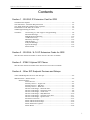
The G2-ISU3 card comprises a specific software version run on the Hybrex G2-VIUS
hardware platform.
The ISU3 essentially acts in the same way as a SIP server in that remote IP phones
“Register” to the ISU3, after which the phones are seen as “extensions” by the system and
receive appropriate signaling.
Similarly to a G2-VIU the ISU3 installs in any trunk slot in a GDS but the ISU3 requires an
80 port cabinet base.
When
•
•
•
installed and configured a G2-ISU3 provides:
Capacity of 3 concurrent voice channels into the host GDS system.
Capacity of 8 connected remote IP extension phones generally.
Capacity of up to 24 connected extensions when the ISU3 is located in the last
cabinet trunk slot (9) and no PRI ISDN card (G2-PIU) is installed in the same
cabinet.
• Available Codecs for voice are G723(6.5), G729, G711u, G711a.
• Post Dial DTMF : currently only SIP INFO style is fully supported.
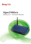
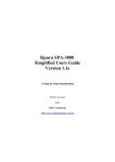
G2 - ISU3 Hardware
Fig. 1.1
1-2
Hybrex GDS IP Extensions Technical Guide
Section 1 : G2-ISU3
Ground Rules
Before describing ISU3 setup and other items there are basic requirements that must be
met if deployment and functionality is to be successful. Following that the various configuration options will be described as the choice of configuration will affect the ISU3 card
settings made.
Network Requirements:
Using the Internet generally as the conduit for VoIP deployment has some level of uncertainty regarding the transport of voice traffic. Voice traffic is “real time” traffic reliant on
minimal, preferably constant, delays and minimal loss of data “packets” for a quality result.
What this means is that network congestion and other factors can markedly affect quality.
In general data transport across the Internet is managed on a “best effort” basis so the
expectation that VoIP telephony will be equivalent in quality to the circuit switched methods known to date, whilst achievable in many cases, is not to be expected as a given.
Short of attaining specific Service Level Agreements from able Internet Service Providers
(ISP), the first line of defense against the above is to choose where possible a reliable ISP
who has preferably a low contention ratio (ratio of bandwidth sold out front to what their
backbone connection is capable of). This includes the first point of connection: the DSLAM
at the local exchange - if the ISP owns it the situation is better than otherwise. If the ISP is
able to qualify traffic according to Type of Service (ToS or “Diffserv”) this is better because it
allows voice traffic priority at the outset. Apart from the other considerations noted below
in general the old maxim applies : “you get what you pay for”.
Dedicated Connections are recommended:
This applies to any form of VoIP where multiple channels are to be carried. For VoIP trunking, and for the subject of this document the ISU3 card, it is strongly recommended that
the Internet connection for this equipment is dedicated to voice. Where an Internet conduit
carries other data, for computers, email, etc. it is general experience that there will always
at some point be data contention resultant in voice quality decline, breakup, and even
decimation in the worst cases. Where the connection is asymmetric (ADSL) the most vulnerable direction is upload as this will have the lowest bandwidth. In locations where single
IP extensions are deployed the dedication of the connection is impractical—in this case
however the user is usually in a situation where there are few other computers etc connected and they are aware and to some extent in control of the traffic situation. However in
a larger office where one or more ISU3’s are installed—dedicate the Internet connection for
voice, your customer will thank you for it.
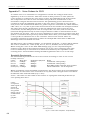
Bandwidth Requirements:
The bandwidth required for VoIP is dependant on the codec employed for the connection.
The codec is essentially the compression algorithm used for the voice data. Whilst the
G711u and G711a codecs are available, supported, and represent virtually no compression
- giving the highest voice quality - they have a high bandwidth price: 90 Kbps per channel,
and are relatively intolerant of packet loss: i.e. quality degrades quickly with packet loss.
At the other end of the scale G723-6.5 is also available to use and requires on 22Kbps per
channel. G723 however is only useful where there the network has minimal delays and
losses, e.g. LAN only deployment, as it quickly degrades with increase of these factors.
The recommended codec, providing the best performance/bandwidth trade-off is G729.
G729 requires 30Kbps per channel. So one ISU3 card, with a 3 channel capacity, is going
to require 90Kbps for voice plus some allowance for command and other network traffic.
It is recommended then that the minimum dedicated ADSL account for one ISU3 card ,
using G729 codec, is a 512/128 account. From experience this type of account will usually
provide something like ~480Kbps down and ~110Kbps up which is ample for one ISU3. If
multiple ISU3’s are to be employed the bandwidth requirements will increment in proportion with the likelihood of a “symmetric” ADSL account (e.g. 512/512) being the preferred
supply option.
1-3
Section 1 : G2-ISU3
Hybrex GDS IP Extensions Technical Guide
ISU3 Network Configuration Options
There are four basic network configurations for the ISU3. Which of these is chosen will
depend on where the IP extension devices are to be deployed and the network facilities
available.
The four types are:
1. LAN or VPN Intranet only
2. NAT Configuration
3. PPPoE Configuration
4. Public IP Assignment
Network Type 1 : LAN or VPN Intranet Only
This type would be chosen where IP extension devices are to be deployed across a LAN, or
at other locations via a Virtual Private Network (VPN), only. An example would be remote
extensions distributed across an education campus, or a multi-site business where a VPN
was available. A note of caution for both examples would be: since the network is likely to
be shared with data traffic that specific attention needs to be paid to traffic prioritization,
i.e. Quality of Service (QoS) issues - usually by combination of router/managed switch
programming and ISU ToS settings - so that voice traffic has high, or highest, priority.
Establishing connections across a LAN is basic in that the LAN router manages the traffic
internal to the LAN – to and from the privately addressed devices. Traffic across a VPN is
managed similarly in that a VPN is like a segmented LAN where the routers concerned will
pass traffic to the relevant segment according to device addresses - the addresses again
being private. This type of network will not be able to establish connections with any IP
extension devices that are not located in/on the particular LAN or VPN. I.e.: IP extension
devices will not function with this setup if connection is attempted from an arbitrary location on the Internet.
For this network type the prime requirement is the ISU3 must be assigned a fixed IP address.
Network Type 2 : NAT Configuration
This type of network will be the most commonly implemented type as it offers the best
advantages for the resources deployed. IP extension devices can be located at any arbitrary
location with a broadband Internet connection. These IP ‘stations’ can connect from behind
most modem/routers (Network Address Translation, or NAT, firewalls) automatically, without any special settings having to be made at that location. The IP extension devices are
also location portable - they can be moved to wherever desired and when plugged back into
a broadband Internet feed, register with the ISU3 and are once again a live extension of the
GDS.
The ISU3 device (or devices) are connected to the Internet via a standard modem/router.
With a series of port forward settings made on the router, and the known WAN IP address
of the Internet connection along with some other settings programmed into the ISU3, the
ISU3 behaves as if it were directly connected to the Internet, hence allowing Internet distributed IP extensions. Multiple ISU3’s can also be configured on the one account using
variant port sets.
The requirements of this setup are :
(a). The Internet access account used must have a “static” (not dynamic) WAN IP address.
This is because the ISU3 must be at a known, constant, and contactable, address for
the IP extension devices to connect to. Note: in the absence of a static IP there are
other measures that can be employed such as DynamicDNS but these require specific equipment and are not without possible problems - static is the recommended
option. (See appendices for further information)
(b) The type of modem/router employed can have significant effect on performance - see
appendices for recommended types.
1-4
Hybrex GDS IP Extensions Technical Guide
Section 1 : G2-ISU3
There is another advantage for the NAT configuration in that the broadband connection, set
up for the ISU3, can also be configured to allow remote programming/maintenance of the
ISU3 card itself and even the GDS MPU if desired. In this way one of the hurdles of integrators - that of resistance of the IT departments of some organizations to allow any form of
connection to their LAN of equipment they are unfamiliar with (e.g. GDS MPU) - is overcome. This is of course unless the use of GDS CTI (HybrexCAS, TAPI etc) forces that issue.
Network Type 3 : PPPoE Configuration.
Like NAT configuration, PPPoE configuration allows deployment of IP extension devices
across the Internet to any location with a broadband Internet connection, with location
portability. PPPoE stands for Point to Point Protocol Over Ethernet and is the common form
for clients to connect with an ISP. In the PPPoE process the client (in this case the ISU3) is
assigned the public address (real Internet IP) of the account. This is one way of obtaining a
real IP which is a prime requirement for a “registrar” such as the ISU3, although this has
been somewhat overtaken by the ISU3 programming now allowing IP sharing as the NAT
configuration demonstrates.
In PPPoE mode the ISU3 is connected to the Internet feed via a modem set in bridge mode.
There is a mandatory requirement of a “static” IP for the Internet connection meaning the
Internet feed will most likely be ADSL or variant, as this requirement is not often met by
other forms of connection (e.g. Cable in particular). This static IP is then the address of the
ISU3 for the purpose of IP extension registrations and connections.
Because the ISU3 is then the account client and does not contain a switch or router the
Internet account is therefore automatically dedicated to this one ISU3 card. This rules out
this method for multiple ISU3 installations (unless a separate account is used for each card
which may only be viable if 512/128 accounts were all that was available).
Advantages are few but PPPoE mode does provide direct connection to the ISU3 for remote
programming/maintenance and a clean and simple setup where one ISU3 is to be deployed.
Network Type 4 : Public IP Assignment
As per types 2 & 3 the assignment of a public IP (real Internet address) to an ISU3 allows
deployment of IP extension devices across the Internet with aforementioned advantages.
Public IP assignment requires the availability of real IP’s, usually obtained by leasing a
group of them known as a “subnet”, which are then routed onto the network containing the
ISU3/s. If this approach is taken the mandatory “static” IP requirements are automatically
met, with a 4 IP subnet being the minimum requirement for one ISU3 (first and last addresses cannot be used, middle two: one is assigned to ISU, the other is usually assigned to
the router as a gateway). Where more than one ISU3 is to be deployed the next available
subnet size is 8 IP where there are 6 available addresses. This information is relative to
situations where you, the integrator, are handling the entire setup and have the requisite
IT experience to do so. There will be situations where this method is employed because the
IT department/support for the client network, where the ISU3/s are to be situated, are able
to supply public IP/s for use. If they are able to supply this service then the relevant details
(IP address/s and gateway IP) will be provided by them.
The caveat is that if public IP’s are used this implies a larger network where voice will most
likely be sharing bandwidth with data so Quality of Service (QoS) measures must be employed to maintain voice integrity. This is usually done by combination of router/managed
switch programming and ISU3 ToS settings - so that voice traffic is allowed high, or highest, priority.
1-5
Section 1 : G2-ISU3
Hybrex GDS IP Extensions Technical Guide
Installation of G2-ISU3 in a GDS
GDS Requirements:
MMD80 - 80 port GDS cabinet - is required as the base system.
Installations in converted 64 port cabinets or 40 port cabinets are not currently supported.
GDS Software: minimum software required is MPU: G3-E050v, IPU: W0bmbb at this time.
Please update the GDS to the above or later software versions before installation of G2-ISU3.
Preliminary GDS programming settings:
Please set :
05-12-01 = 1 - (hangup) - this enables the remote extension transfer method.
05-14-06 = 3 - this delays Caller ID, enabling proper reception by SIP endpoint devices.
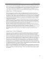
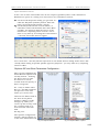
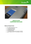
ISU3 Placement :
Fig. 1.2 ISU3 Mounting Positions
Power down the GDS and install the G2-ISU3 card in the selected slot.
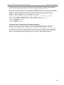
Power the GDS back up and after allowing a couple of minutes for the system to initialise,
connect and log onto GDS System Programming where you can check the ISU3 has been
recognised by the system by selecting : Technical Program > Card Installation
For example:
Fig. 1.3 GDS Technical Program - Card Installation
1-6
Hybrex GDS IP Extensions Technical Guide
Section 1 : G2-ISU3
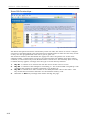
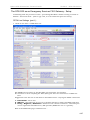
GDS Programming for ISU3
As previously indicated the ISU3 can be installed in any trunk slot in an 80 port cabinet.
When the ISU3 is installed in any of Slots 5 through 8 : 8 extensions can be registered on
that card. If the ISU3 is installed in Slot 9 : 24 extensions can be registered except when a
G2-PIU card is installed in the same cabinet in which case available extension positions
revert to 8.
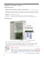
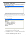
Extension numbers are set up in System Programming > Mode 21 : Port/Station Number.
Select the slot the ISU is installed in and enter the desired extension (station) numbers for
the remote IP extensions (1). Click [Save] when done.
Where an ISU is located in Slot 9, and no PRI (G2-PIU) card is fitted in the same cabinet,
the extra station numbers available are then programmed into the following virtual slots
(xa,xb).
As and when the IP extension devices (SIP phones) individually register successfully with
the ISU3 card the “Type” field will show “IP Phone” for each registered device (2).
For Example :
Fig. 1. 4 GDS programming - Mode 21
Having determined and set the extension numbers for the remote IP extensions in Mode 21
these extensions can then be treated the same as any other extension in GDS system
programming. Bear in mind the (user) functionality of any SIP endpoint devices, other than
Hybrex IP handsets, will be same as an analogue (SLT) extension.
1-7
Section 1 : G2-ISU3
Hybrex GDS IP Extensions Technical Guide
G2-ISU3 : Connecting to, and Login to Programming
As with all VIU platform cards the ISU3 is setup by programming via its Web interface.
This Web interface is available via a Web browser on any computer (PC) connected to the
ISU3, either directly connected via a “crossover” Ethernet cable to the LAN port of the ISU3,
or by standard Ethernet patch cables via a router or Ethernet switch to the ISU3 LAN port.
Fig. 1.5
The only requirement apart from the above cable type is that the Ethernet (IP) address of
the PC in use must be in the same subnet as that of the ISU3. This can be achieved by one
of two methods. Which method is employed can be influenced by your experience level, but
is ultimately dependent on what the target configuration is (see Network Config. Options)
and your desire to reduce the setup steps involved.
The first method is to set the IP address of the PC so that it is in the same range (subnet)
as the ISU3 default address (See Appendices : PC IP Address Setting). The extra work
involved in this method is that if your PC, or laptop, does not usually have this address you
will need to set it back to normal afterward; you may also need to re-set the IP if the ISU3
address is changed in the setup process, so that you can maintain programming contact
with it.
The second method is to use a serial cable to connect from the PC to the ISU3 Console
port, and then use the console interface of the ISU3 to set the IP address of the ISU3 to the
desired address initially. Then the PC can be connected to the ISU as above for
programming setup with generally no other IP changes necessary. This second method is
also useful if the ISU3 IP address is other than default and/or unknown initially. For
details of this method see Appendices : ISU3 Console Methods.
The factory default Ethernet address of the ISU3 is http://10.10.10.6:30061
With PC connected as above, and presuming the ISU3 is at default IP, launch your Web
Browser (Internet Explorer, Firefox, etc) and type the above address into the address bar.
If your connections and device addresses are correct you will get the ISU3 login dialog.
Viz:
Fig. 1.6
ISU3
Login Dialog
Enter the default username : voipadmin and password : admin .
Then click [OK].
1-8
Hybrex GDS IP Extensions Technical Guide
Section 1 : G2-ISU3
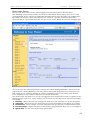
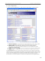
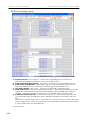
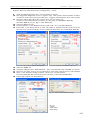
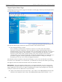
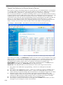
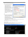
After Login (and sometimes a short wait) the first page presented will be the Information Page.
Viz:
Fig. 1.7
Information Page
The information items of note on this page are the Software Version, and Bootrom Version.
The rest of the ISU3 web interface is navigated using the page links in the lower section.
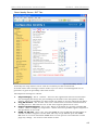
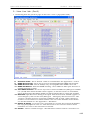
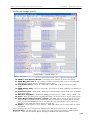
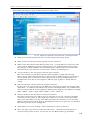
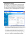
Network Settings
Presuming setup from default - the first settings to be made will be the network details.
Click on the “Network” link and the following page will be shown :
Fig. 1.8
Network
Configuration
Page
1-9
Section 1 : G2-ISU3
Hybrex GDS IP Extensions Technical Guide
The default Network type is “Static”.
The settings to be made (if not already done so by the Console method) are :
Network IP (the IP address of the ISU3 itself), Subnet Mask (of the network or subnet), and
Network Gateway (the IP address of the network border router).
For network configurations of types 1 & 2 (LAN and NAT’d) these will be private IP
addresses and mask for the LAN the ISU is to be connected to. The same applies to network
type 4 (Public IP) with the exception that real IP’s and more restricted subnet mask will be
used.
If you are in control and setting up a dedicated connection these will be known. If you are
connecting to a business network (or VPN) you will need to obtain an IP address (and other
details) to use from the network administrator
When the desired settings are made - remember to click [Submit] before leaving the page.
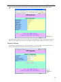
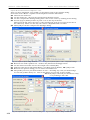
PPPoE Network Setting
If the network configuration to be used is PPPoE - click on the [PPPoE] button and the
following page change will be displayed :
Fig. 1.9
Network
Config.
PPPoE
The settings to be made here are the PPPoE username and password.
Since PPPoE mode is usually a direct connection (via a bridge-mode modem) to the ISP’s
broadband feed, or “account” as it is generally known, these are the username and
password necessary to connect to the “account” and will be supplied by the ISP.
After setting these remember to click [Submit] before leaving the page.
NB: If a mistake is made in these settings preventing a login to the ISP then the Console
method must be used to issue the command “set dhcp off” and then set an IP (eim ip)
before the Web interface of the card can be regained to correct the error. See
Appendices :Console.
The Network IP, Mask, and Gateway fields will show the real IP etc of the account (and
therefore the ISU3 IP) after the PPPoE login is successful as they are supplied by the ISP
equipment as part of the login process. Since the (ISU) requirement is for a “static” IP this
will usually be known beforehand. If not it can be discovered via the Console method (eim
ip) after login. The IP will need to be known to browse to the ISU3 at any later stage,
moreover it will be used as the “Registrar”, and usually “Proxy”, address to be set in any
SIP endpoint device used as an extension.
1-10
Hybrex GDS IP Extensions Technical Guide
Section 1 : G2-ISU3
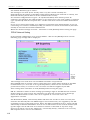
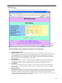
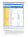
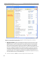
OutBound Proxy
Click on the “OutBound Proxy” link and the OutBound page will be displayed :
Fig. 10
OutBound
Proxy Page
The OutBound Proxy page is not quite as it sounds.
On the ISU3 this page determines the traffic portal for traffic of both directions but more
importantly incoming as the settings here determine the network identity of the ISU3 with
respect to voice connections from the SIP endpoint devices being used as extensions.
The mandatory settings are the RTP IP, RTP Port, and SIP Port. Remember to [Submit].
1. RTP IP :
For all network types (configurations) except type 2 (NAT’d) this will be set to the IP
address of the ISU3 itself. For the PPPoE type this may need to be set after the
inherent real IP address granted by the ISP is discovered.
For a NAT’d network this IP address will be set to the WAN IP address of the router
the ISU is situated behind. The router will then be set to “Port Forward” the ports
described below to the LAN IP address of the ISU3.
2. RTP Port :
This will be set to the start port of the port range used to transport incoming RTP
voice connections. The port range to use is recommended at 100 ports so the “Port
Forward” range to set on the router - for the default 2070 shown above - will be 2070
to 2169 UDP. If multiple ISU3’s are set up in the same NAT’d network : successive
ISU start port (and ranges) must be staggered to prevent collision. For example ISU31 at 2070 to 2169, ISU3-2 at 2170 to 2269, etc.
3. SIP Port :
For the ability to setup multiple ISU’s the SIP port is also configurable here.
In the same way as (2): ISU3-1 set to 5060, ISU3-2 set to 5061, etc. all UDP. This is
only a single “Port Forward” to the ISU3 LAN IP to set on the router, for and to each
ISU3 installed. NB: this port setting must also agree with set on the SIP Proxy page.
4. Domain Name Server:
This setting is optional. It is not really necessary because the usual setup of the ISU3
is done with IP addresses, and not full domain names that need resolving, so disable.
The exception to this would be if DynDNS services usage was forced - see
Appendices.
1-11
Section 1 : G2-ISU3
Hybrex GDS IP Extensions Technical Guide
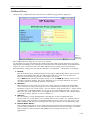
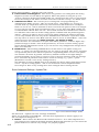
SIP Proxy Settings
Click on the link for “SIP Proxy” and the main SIP Proxy page will be displayed :
Fig. 1.11
SIP Proxy
Page
The SIP Proxy page determines the SIP “Registrar” settings for the ISU3 among other things.
1. SIP URI address :
This is the “SIP Registrar” address.
This is set to the same address as the RTP IP address on the OutBound Proxy page.
It is also the address that will be used as the “SIP Registrar” parameter for the
programming of the SIP endpoint devices set up as IP extensions.
2. SIP URI Port :
This is the “SIP Registrar” port.
Set to the same value as the SIP Port on the OutBound Proxy page.
As per the notes on the OutBound Proxy page this port value may vary where more
than one ISU3 is installed. As per (1) above this is also the “SIP Registrar Port”
parameter for the SIP endpoint device/s programming.
3. Expire Time and Options Interval Timer :
Sets the registration interval (seconds) for SIP endpoint devices. Set both these fields
to a value less than the expected port binding time of the router/s the SIP endpoints
will be situated behind. Just under 3 minutes (180 sec) is usually acceptable. The
endpoint devices are then instructed to maintain this interval or less, so maintaining
contact with the ISU.
4. Phone Numbers : On the ISU3 these are a porting number value that the GDS uses
for control. They will usually be left at the default value (999).
However the rule is : no other extension in the GDS system must be given the same
number. So if extension number 999 already exists on the GDS, either the ext. No. or
the “Phone Numbers” must be changed or faulty operation will result.
This also applies to the “Phone Number” on the SIP Proxy2 page.
1-12
Hybrex GDS IP Extensions Technical Guide
Section 1 : G2-ISU3
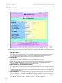
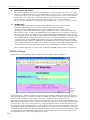
DSP Settings :
Click on the “DSP Setting” link and the DSP Settings page will be displayed :
Fig. 1.12
DSP
Settings
Page
The DSP Settings page determines the parameters of the voice link.
The above graphic shows the preferred settings, not the default page.
1.
2.
3.
4.
Default Voice Codec:
Whilst the ISU3 is auto sensing with regard to voice compression codec in use, the
default (highest priority) codec needs to be specified. (For more information on codecs
see appendices :Voice Codecs). The recommended codec for general use is G729.
This setting is made by selecting from the drop menu shown by clicking the ellipsis
(down arrowhead) at the right of the value field.
Out Volume:
Determines the voice volume transmitted from the ISU to the SIP extension devices.
A setting of between 5 and 10 has been found to give acceptable levels for send
volume. Set by select from the ellipsis drop menu. Can be adjusted to taste.
In Volume :
Determines incoming volume translation of voice data stream from SIP extension
devices. Like a gain adjustment, adjust to 0 (or taste) by selection from the ellipsis
drop menu.
Receive Buffer :
Determines the size of the buffer used for incoming voice packets. Both this and the
following item will follow a default setting when the codec setting is submitted. Can be
adjusted according to network needs. Trade-off is: the larger the buffer the more
tolerant of network voice packet transit time differences but the higher the voice delay
incoming from SIP endpoint to the system.
1-13
Section 1 : G2-ISU3
Hybrex GDS IP Extensions Technical Guide
5.
Voice Frame per Packet:
As with the previous item this value will follow a default setting when the voice codec
setting is submitted. Relative to the Small/Med/Large settings : actual milliseconds of
voice per packet varies according to codec. Can be adjusted - but test voice if altered.
Trade-off is : the larger the voice frame size the less packets are sent to network but
the quicker the voice quality will drop off if packets are lost on the network.
Do not use the “Medium” setting when using G729 codec - one way voice may result.
6.
DTMF Relay :
This parameter determines how post dial DTMF is sent across the network.
From the ellipsis drop menu it can be seen there are three options :
“Disable” means DTMF will be sent as tones within the voice (audio) band.
This option suffers markedly when higher compression codecs are used (G729 and
particularly G723). In effect the DTMF tones get mangled by the compression process
and any packet loss exacerbates the problem making the DTMF hard to detect at the
receiving end. Currently GDS functions will not respond to commands using “Disable”.
“Inband(RFC2833)” is not functional in the code set of the VIU/ISU3 card - don’t use.
“Outband” means the DTMF digits will be sent as an information packet in the SIP
command stream. Known as “SIP Info” style DTMF, this is the most reliable available
and recommended for use. When the Outband setting is chosen SIP endpoint devices
used as connected extensions also need to be programmed for “SIP Info” DTMF.
The last field “Payload” is related only to RFC2833 DTMF and therefore not relevant.
TOS/DS Settings
Click on the “TOS/DS” link and the Type of Service page will be displayed :
Fig. 1.13
TOS/DS
Page
Type of Service / Diffserv relates to Type of Service (TOS) or Differentiated Services Code
Point (DSCP) which is a method of packet marking that allows enabled network routers to
prioritise the handling and passage of packets according to their marked value.
Appropriately marked packets, in this case VoIP packets, are thus afforded priority which
may reduce transit times and/or packet loss and thus alleviate voice quality problems from
these sources. The use of, and value set, of this parameter will be dictated by instruction,
by network system administration, or ISP support. Since our recommendation is dedicated
network porting for the ISU and its voice traffic, these settings are most relative to the ISP
supporting this connection. This represents an option that can and should be taken up if it
is supported by your ISP. Note: the value set in this field is entered in hexadecimal form
and constitutes the entire TOS/DSCP octet value.
1-14
Hybrex GDS IP Extensions Technical Guide
Section 1 : G2-ISU3
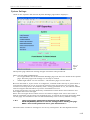
System Settings
Click on the “System” link and the System Settings page will be displayed :
Fig. 1.14
System
Page
The System page allows the setting of login usernames and passwords.
There are two login qualifications:
•
User login allows edit of the Network Settings page and the User details of the System
page. All other pages and settings can be only be viewed.
•
Admin login allows “access all areas” - all interface pages can be edited.
Because the ISU3 is, by its nature as a Registrar, available either directly or ported from a
real Internet address it can be accessed by browser from any Internet access point. For
reasons of security then it is mandatory that a strong password be set, for both the Admin
and User login authentications to prevent unauthorised access.
A strong password is any non-dictionary combination of both letters and numbers of at
least eight characters in length.
Since the User login doesn’t allow much to be edited it might seem safe to leave this at
default. IT IS NOT ! If the string “set default factory” is entered in the Login Username field
on this page and submitted: the card will immediately reset to factory default settings.
1&2
Enter appropriate passwords for both User and Admin logins.
Click the [Submit] button to save the settings before leaving the page.
Make a note of the passwords set in your install notes !!
The Time Zone and Server settings are not of any consequence for this implementation.
1-15
Section 1 : G2-ISU3
Hybrex GDS IP Extensions Technical Guide
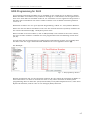
Phone Book
Click on the “Phone Book” link and the Phone Book page will be displayed :
Fig. 1.15
Phone Book
page
Unlike other implementations built on the VIU hardware platform the ISU3 Phone Book
page is not editable. What the ISU3 Phone Book page shows is the status of the IP
extension settings and devices :
1. Phone No. :
The Phone No. column shows the extension numbers allocated to available positions
(ports) in GDS programming Mode 21 - see Fig 4 (pp8). Ext No’s shown are example only
As noted elsewhere: the ISU3, when mounted in any GDS trunk slot has eight ports
available for IP extension assignment and therefore device registration. The exception is
when the ISU3 is mounted in slot 9 where the following virtual slots “a” and “b” can also
be used for IP extension assignment/registration - provided no ISDN PRI card is fitted in
the same cabinet. If this option is taken up these extra extension positions will also
show in the above phone book.
Please note: The mentioned GDS virtual slots xa & xb are used for ISDN PRI or ISU3 use
only (mutually exclusive) - no other use is supported.
2. Status :
The Status field shows the dynamic status of connected IP extension devices.
Only the first position is used with i=idle, r=ringing, t=talking, n=not registered.
3. Destination :
The Destination field shows the real or virtual IP address of devices that are registered
(and therefore available) or “not REG. yet” (not available) as the case may be.
All other fields show standard listing details as shown. The “Add New Entry” block, and
Edit/Delete buttons, are inoperative in this implementation.
1-16
Section 4 : Other SIP Devices
Hybrex GDS IP Extensions Technical Guide
Section 4
Other SIP Devices
Contents
Other SIP Endpoint Devices and Setups ........................................................ 4-2
SIP Handsets : Snom Series........................................................................... 4-2
Snom Phones :
Index Screen ........................................................................... 4-3
Identity Screen - Login Tab...................................................... 4-4
Identity Screen - SIP Tab ......................................................... 4-5
Identity Screen - RTP Tab........................................................ 4-6
Advanced Settings - Network Tab ............................................ 4-7
Advanced Settings - behaviour Tab.......................................... 4-8
Advanced Settings - Audio Tab ................................................ 4-9
Advanced Settings - SIP/RTP Tab.......................................... 4-10
Advanced Settings - QoS/Security Tab .................................. 4-11
Advanced Settings - Update Tab ............................................ 4-12
Preferences Screen ................................................................ 4-13
Snom 320 Function Keys ...................................................... 4-15
Snom 300 Function Keys ...................................................... 4-16
Snom Firmware Update......................................................... 4-17
Snom Notes........................................................................... 4-18
Analogue Telephone Adapters ...................................................................... 4-20
Linksys SPA3102 ATA......................................................................... 4-20
WAN Port IP Setup ................................................................ 4-21
SPA3102 Setup for ISU3 IP Extension Use ............................ 4-22
A Voice - SIP Tab ............................................................. 4-22
B Voice - Regional Tab ..................................................... 4-23
C Voice - Line 1 Tab......................................................... 4-24
Notes on SPA3102 as IP Extension Device ............................. 4-26
SPA3102 as Emergency Services local FXO Gateway ............. 4-27
PSTN Line Settings............................................................ 4-27
Snom Phone Settings for SPA3102 as Local ES FXO.............. 4-30
Softphones
............................................................................................. 4-32
SJphone Softphone............................................................................. 4-32
Audio Wizard..........................................................................4.33
SIP and Other Parameters Setup ........................................... 4-35
SJphone Notes ..................................................................... 4-39
4-1
Section 4 : Other SIP Devices
Hybrex GDS IP Extensions Technical Guide
Other SIP Endpoint Device Options and Setups
Since the purpose of the ISU3 implementation is to form IP remote extension capability for
GDS systems, it would be imagined that any device that conformed to the SIP protocol (RFC
3261 et al) could be used as a remote endpoint device. Unfortunately this is not the case.
Due to differences in protocol implementation by various manufacturers not all SIP equipment is interoperable. For this reason the following guide has been prepared detailing equipment that has been tested against the ISU3 and found functional, and the setup details of
such.
It must be remembered from the outset that :
• Apart from the superceded Hybrex HP300 IP Phone, and the soon to be released new Hybrex IP-3861 SIP phone (which will display DSS/BLF etc similarly to a digital system handset) most if not all other endpoint devices will provide SLT (analogue extension) functionality in use. This includes call transfer, all other system SLT features such as call forward
etc, including access to system voicemail (if fitted in the parent system).
• Although the ISU3 can register commonly eight, but up to twenty-four (conditional), extension devices the ISU3 hardware base only supports three concurrent active calls. Unlike
the Hybrex SPU90 proxy server the ISU3 does not proxy calls between remote extensions,
each active call is a call into the parent GDS just like any other system extension. This
allows call handling in a true “extension” sense with all of the inherent advantages of such.
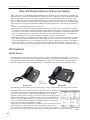
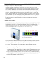
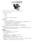
SIP Handsets:
SNOM Series:
The European manufacturer Snom produces a range of SIP phones which have a very elegant European style and extensive programmability. The most obvious handset for use with
the ISU3 is the Snom300, with the Snom320 also open to consideration. The 320 however
may be a little underutilised considering it’s capabilities if it is only used for ISU3 work.
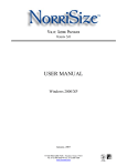
Fig. 4.1
Snom Phones
Snom 300
Snom320
Full Details of these phones can be found here: http://www.snom.com/en/products.html
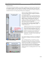
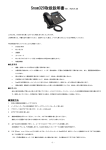
The Snom phones are fairly easy to set up. They are by default set
to obtain an IP address automatically (DHCP) so after unpacking
and connecting to power and network (LAN) they are ready to
program. Some basic settings can be made from the keypad of the
phone itself, however to set them up the way we need initially we
need to use their Web interface. To do this it is necessary to discover the IP address the phone has obtained which can be done
using the manual excerpt shown at right.
Then open a browser (IExplorer or other) on a PC connected to the
same network as the phone and enter the phones IP in the address field : for example http://192.168.1.10, then tap the Enter
key. The various web pages obtained and the settings to make are shown following.
4-2
Fig. 4.2
Snom IP
Hybrex GDS IP Extensions Technical Guide
Section 4 : Other SIP Devices
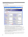
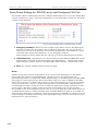
Snom Index Screen
Below is the first screen shown when logging onto the Snom phone Web interface.
The following setup screens shown are those of a Snom320 which will be seen to be a very
programmable device. The more applicable Snom300 phone has the same type of Web interface with the exception that some features are reduced - eg fewer “Identites” and fewer
“Function Keys” -apart from those the setups are the same. Phone IP shown is example only.
Fig. 4.3 Snom index screen
As can be seen the index page shows call logs and allows dialing PSTN No.s direct from the
page from the “Dialed Numbers” list only. This is due to the prepended 9 necessary for system trunk access. However dialing by click for extension call records works from all lists.
Your attention is now called to the menu on the left hand side.
The menu items required to be set up are tagged in level of importance and as a guide to the
following page sequences. Other settings can be made but the important ones for operability
are shown:
1. Identity : where the relevant settings are made for each “identity” set up for the phone.
2. Advanced : where setups are made that govern the operability of the phone as a whole.
3. Preferences : where setups are made that affect the operation in a preferential manner.
4. Function Keys : where functions of the phone’s programmable keys can be re-assigned.
5. Speed Dial : for the entry of personal speed dials.
4-3
Section 4 : Other SIP Devices
Hybrex GDS IP Extensions Technical Guide
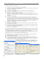
Snom Identity Screen - Login Tab :
Fig. 4.4 Snom Identity - Login Tab screen
The Login Tab is the default entry point for any Identity:
1. Identity Active : On by default. On = Identity will register with specified server.
If a particular Identity isn’t required for normal use then set to Off - will reduce traffic.
2. Account : Is set to the SIP Account Number - for now this is the Extension Number
allocated in host GDS programming (one with ISU3) for this IP extension phone.
3. Registrar : Is set to the WAN IP and port of the ISU3 card - see ISU3 setup section 1.
4. Outbound Proxy : Not generally used for this implementation - may be used according to Network Admin instruction (special cases).
5. Call Records : Set according to preference - default is On.
6. Save : Remember to Save any settings made before leaving the page/tab. NB: when
settings are changed there will often be a prompt to “Reboot” the phone - allowing
settings to be applied. This is only necessary after all setting changes have been
made.
7. You will notice the question prompt on all setting parameters - clicking this icon will
take you direct to an Internet Wiki for Snom features (Internet access required).
This is useful for explanations but by no means absolutely comprehensive.
As noted prior - other settings can be made if desired (or for experiment) - the main
ones for this implementation are detailed.
4-4
Hybrex GDS IP Extensions Technical Guide
Section 4 : Other SIP Devices
Snom Identity Screen - SIP Tab :
Fig. 4.5 Snom Identity - SIP tab.
Generally the setup shown can be used in it’s entirety as this is functional.
As noted before other settings could be made if you are brave or knowledgeable but no
guarantee is given of operability other than stated.
The important settings are shown :
1.
2.
3.
4.
Proposed Expiry : Set to 1 minute - this sets the registration interval and therefore
the messaging that keeps the port bindings on the NAT router this phone is likely
behind. These port bindings are what enable the phone to receive calls from the ISU3.
Long SIP Contact : Set to OFF - this is the verbose form of Contact annunciation in
the SIP protocol - ISU3 doesn't use it and won’t register phone if it is used.
Support Broken Registrar : Set to ON - Phone is designed for use with complex SIP
servers - ISU3 is simpler by comparison - Phone won’t accept ISU3 register response if
this parameter is set to off.
DTMF via SIP Info : Set to ON - post dial DTMF is sent via SIP Info method which is
reliable and ISU3 supports. In fact ISU3 will only accept SIP Info post dial DTMF.
NB: there is an issue with Snom DTMF that is in the process of rectification so this
page may change - see notes at end of this section.
4-5
Section 4 : Other SIP Devices
Hybrex GDS IP Extensions Technical Guide
Snom Identity Screen - RTP Tab :
Fig. 4.6 Snom Identity - RTP Tab.
The Identity - RTP Tab allows the setting of the Codec priority and other RTP protocol
parameters for this identity :
1. Set the required Codec type for your planned implementation. See Appendices : Codecs
The codec order set will be used according to order of priority, and availability and/or
capability of the connecting equipment - for example codec “1” will be used if the distant equipment supports it, otherwise codec “2” will be used, and so-on.
2. The settings shown work. Other settings may or may not.
RTP encryption must be set OFF as the ISU3 does not support it.
Note : The Identity - NAT tab settings are not used for this implementation
- they allow setting of STUN servers and such, commonly used for P2P and server-less
connections under certain circumstances (not effective with symmetric NAT firewalls) STUN is not used by the ISU3 as it is engineered as a registrar/server.
4-6
Section 4 : Other SIP Devices
Hybrex GDS IP Extensions Technical Guide
Snom Advanced Settings : Network Tab
Click the menu “Advanced” link for the Advanced tab set :
Fig. 4.7 Snom Advanced Settings - Network Tab
As with other pages the Advanced Settings will mostly be left at default.
Relevant settings changes only are shown :
1. DHCP : The decision to change from default of DHCP ON will be based on whether the
phone will be remotely administered by port forwarding to it through the border router.
If remote administer is desired the IP address of the phone must be fixed (DHCP = OFF)
2. IP Address : If DHCP is Off the phone must be assigned a fixed address, and this must
be set to an IP outside of the routers DHCP “pool” (see network administrator for IP
grant). The Subnet Mask and Gateway will already be known if the phone is already on
the destination network; if not relevant values for the destination network are entered.
3. DNS : Enter the preferred DNS server IP’s for the ISP network the phone is connected to.
4. Timezone: Select the relevant timezone for your location, as time is shown on the phone
5. HTTP port: Change only if you have a specific plan in mind - for example you want to
set up remote access to the Snom phones and the router the phones are behind cannot
do port redirect, only port forward. So each phone needs to be set to a different port for
web access and you will browse to them using only that port.
4-7
Section 4 : Other SIP Devices
Hybrex GDS IP Extensions Technical Guide
Snom Advanced Settings : Behavior Tab :
Fig. 4.8 Snom Advanced Settings - Behavior tab
The Behavior tab, as the name suggests, governs aspects of the phone’s behaviour.
The options are numerous, and mostly self explanatory.
A working configuration is shown above for you to copy initially.
1. Auto Dial : This can be set to preference - as shown the phone will exhibit a 5 second dial timeout. This can be overridden by pressing the tick key on the phone keypad which then sends the number immediately. If set to OFF the tick key must always be pressed to dial the entered number. Remember to Save any changes.
4-8
Section 4 : Other SIP Devices
Hybrex GDS IP Extensions Technical Guide
Snom Advanced Settings : Audio Tab :
Fig. 4.9 Snom Advanced Settings - Audio tab
Working Config for general audio parameters is shown for you to copy initially.
1.
Volumes : Are adjustable if required - suggest leave at default - otherwise exercise
care if raising as audio distortion can result. Note these are Mic. (send) volumes receive volumes can be controlled at will directly from the phone keypad (Volume
button).
2.
Remember to Save if any changes have been made.
Other observations:
(a) DTMF echo on speaker phone puts DTMF tones out handset speaker.
(b) Keytones means handset speaker will beep for every key press.
(c) Call released notification means handset speaker will beep loudly if distant party
releases before an incoming call is picked up.
(d) Silence Suppression means less data traffic outgoing during periods of silence from
the person using the phone but has the side effect of some clipping of speech and
impressions of the B party that the line has gone “dead” during times the suppression
is active.
These behaviours have been found to be an annoyance to some - hence the recommendation is they be set OFF.
4-9
Section 4 : Other SIP Devices
Hybrex GDS IP Extensions Technical Guide
Snom Advanced Settings : SIP/RTP Tab :
Fig. 4.10 Snom Advanced Settings - SIP/RTP
Working Config for you to copy.
Remember additional information about what each setting means can be obtained by clicking the Question mark icon at the right of each field. On a live phone Web interface and
with Internet access enabled this will provide the Snom Wiki window with the term described.
1.
Dynamic RTP Ports : This is the port range that the phone will use for dynamic
assignment of its outgoing RTP ports. RTP is what carries the voice packets, and each
new call gets assigned new port pairs to avoid call collision. It can be seen that the
default range is very large (16382 ports). A range as large as this isn’t usually necessary, a port range of 200 will suffice. It is suggested that where there are a number of
these phones on the same network (LAN) that each phone be set a port range that is
different to the others as a way of reducing any possible duplication/collision.
Remember to Save any changes before leaving the page (tab).
4-10
Section 4 : Other SIP Devices
Hybrex GDS IP Extensions Technical Guide
Snom Advanced Settings : QoS / Security Tab :
Fig. 4.11 Snom Advanced Settings - QoS/Security tab
This page allows general settings for Quality of Service and Security.
Important points are noted:
1. ToS/Diffserv Settings : ToS/Diffserv packet marking can achieved at the source device,
and determine IP traffic priority in networks so enabled. The packet marking can be
carried from source to final destination if it isn’t stripped by any intermediary device, so
is a very useful QoS measure. The priority scheme is programmed into the network
routers therefore relevant values stated by Network Administration are entered here.
The RTP streams carry voice, and the SIP streams carry command data..
2. VLAN : VLAN is a method for completely separating network traffic from different ‘sets’ of
devices, and an easy way to control bandwidth allowances within the LAN/Intranet being
controlled. As above, these settings, and any immediately below, are dictated by Network
Administration.
4-11
Section 4 : Other SIP Devices
Hybrex GDS IP Extensions Technical Guide
Snom Advanced Menu - QoS/Security Tab (cont’d)
3. Filter Packets from Registrar : This means any packets not coming from the Proxy/
Registrar (in this case the ISU3) are ignored. Since this phone is being set up as a
‘remote’ extension off the Hybrex PBX traffic not coming from that source is not desired,
hence the setting is ON. There are other observances on this concept - see Snom notes.
4. Administrator Mode : The screens you are seeing now and programming are
“Administrator Mode” screens - like “access all areas”. “User Mode” is a severely restricted mode by comparison where only a few functions like Preferences and Speed
Dials etc can be set - this is desirable in most cases from the point of view of an integrator as it reduces trouble from unauthorised “play”. To see what User Mode entails just
set Admin Mode off and ‘Save’ the tab - then check around the available menu choices.
You will also notice that one of the Config options available from the phone keypad is
“Reset” - which is in effect a factory reset of the phone (default all settings). This however is only enabled after the entry of the “Administrator Password”. If you have taken
the step above to observe User Mode and now want to revert to Admin Mode - select the
Advanced menu and enter the Admin password - the default is 0000.
Given the above it is advisable to set your own Admin password - numeric digits only (and don’t forget to make a note of the password !). As a last act when setting up the
phone disable Administrator mode so you can be sure any configuration changes thereafter are authorised.
5. HTTP Server : The meaning of HTTP Server in this sense is the phone acting as a
server - i.e. giving you the web interface you are using to program. The “User” username
and password you set here will be required in a login dialog before access to the phone
web interface in future is granted. The factory default is blank so no login dialog is
presented initially. If you want to restrict access to the web interface make the settings
here. Username & password valid values: character strings, e.g. <john>, <jh24>.
(Remember to make a note of any settings made !).
The following section for HTTP client is for allowing the phone when contacting another
server - say for a Config update - and is not used in the current implementation.
Don’t forget to ‘Save’ if any settings have been changed before leaving the tab.
Snom Advanced Settings : Update Tab :
Fig. 4.12 Snom Advanced Settings - Update
The Advanced - Update tab is for “settings” downloads
These are in the form of an XML file - used for mass deployment so doesn’t apply to us.
The one important thing here is :
1. Reboot : This is where the Web interface Reboot button is - if no other important setting changes have triggered the Snom alternate Reboot link insertion you can reboot the
phone from here to be sure any changes are properly applied.
4-12
Hybrex GDS IP Extensions Technical Guide
Section 4 : Other SIP Devices
Snom Preferences Page
Fig. 4.13 Snom Preferences Menu - 1st half
The Snom Preferences menu is a long page so the first half is shown here. The settings
shown are a guide - being open to user preference - there are some pertinent points however :
1. Message LED : The use of this will depend on preference and also on the settings on
the Identity page > Login Tab for recording of Missed calls. See Fig 4.4 pp4-4.
2. Call Forward Settings : Should the call forward functions available from the Phone
keypad/Nav keys be desired - enter here the Hybrex dial codes for CFwd. Shown is a
common setting for ACF to Voice Mail, with the off code setting relative to this setup
example extension identity of 200. The CFwd Busy, and Timeout (No Answer), settings
can be made similarly.
3. DND : Since the parent system here is a GDS the code for DND is set in GDS programming Mode 22, and then entered here. An example is shown. This has the advantage
that the Snom displays the DND status and the phone function keys can be appropriately programmed for one touch setting. The rules for the code set in Mode 22 are that
it cannot begin with a * or #, and must not be duplicated anywhere else in Mode 22,
extension numbering, or leading digits of PSTN numbers.
4-13
Section 4 : Other SIP Devices
Hybrex GDS IP Extensions Technical Guide
Snom Preferences Menu (second half):
Fig. 4.14 Snom Preferences Menu - 2nd half
This part of the preferences page shows suggested initial settings (most at default ).
There is a relevant point of note however :
4-14
1.
Emergency Numbers : First the Australian 000 needs to be entered in the list. Then :
Emergency services response relies sometimes on known address for action. For the
PSTN world this is a given being attached to the CLI of the caller. For the VoIP world
this has become a grey area, particularly re portability of SIP devices. Snom phones
have a feature where emergency calls can be routed via a different proxy. What this
should be is the IP address of an FXO gateway device connected to the PSTN CO port of
the service supplying the ADSL/2 feed to which this phone is connected. In this way
emergency calls will be forwarded via this port and will bear the PSTN CLI of the relevant premises. The FXO gateway device will need to be appropriately programmed to
accept this traffic. From a regulatory standpoint this emergency facility would be considered mandatory. It is currently suggested that a suitable FXO capable device may be
the Linksys SP3102 which is detailed following.
2.
As before remember to Save any settings changes before leaving the page.
Hybrex GDS IP Extensions Technical Guide
Section 4 : Other SIP Devices
Snom 320 Function Keys :
Fig. 4.15 Snom 320 Function Keys
The Snom 320 has a large number of Function keys which are all programmable.
The purpose of this page is to show some re-assignments that are useful to start with :
1. Soft Key functions : relative to the Snom display when idle. Can be re-assigned according to the drop menu choices shown when the ellipsis indicated is clicked.
2. Retrieve : In this case the key has been reassigned to dial 86 for Hybrex Voice Mail.
3. Transfer : The ISU3 function code for Hold/Transfer is *#. So the pre-labeled Transfer
key is set to (post) dial DTMF the digits *# to enable this function with the ISU3.
4. DND : This key definition is left at default - but the relevant setting is made in Preferences (see fig 4.13 pt 3 pp4-13) to enable this feature. The advantage of using this
function this way is the phone displays the DND status as well as the GDS enacting it.
The key toggles the state in use, but note the extension state change at the GDS takes
a moment or two.
5. Context : The unlabeled keys in the lower section can be set to a “context” (using the
ellipsis) - this sets the “Identity” to which this key is relative. The example setting shows
key P1 to be set to annunciate the “Line” status for the example extension account of
this phone (200) on the test ISU3.
6. Type : The key “Type” can be set from the drop menu obtained by clicking on the Type
field ellipsis for the key. Relevant to the Type a parameter can then be entered in the
field to the right. In this case the example shows key P5 set to “Speed Dial” to dial a
speed number - 1 in this case - from the settings on the Speed Dial page, and the context is the example identity (200 on the ISU3).
7. Remember to Save any settings made before leaving the page.
4-15
Section 4 : Other SIP Devices
Hybrex GDS IP Extensions Technical Guide
Snom 300 Function Keys :
Fig. 4.16 Snom 300 Function Keys
The Snom 300 phone has fewer function keys than the 320; the 300 is of course a simpler
and more economical phone. The function keys available however will cater for many needs
as they are also programmable and can be put to good use.
The methods noted for the Snom320 also apply here since the phones are of the same
software family : ie field values can be set by selection from the ellipsis drop menu where
available, or entered directly in the Number field. Context sets the “Identity” (line account)
to which the key applies; and Type sets the type of action the key initiates.
1.
2.
3.
4.
4-16
Key P1 : is shown set to annunciate the line status of the active account.
Key P3 : is shown in this example to be dialing *0 - the normal GDS “call pickup” code
enabling calls ringing on another extension to be picked up.
Key P5 : is shown set to dial *# which is the Hold/Transfer code for the ISU3 - this
key would then be labeled “Transfer” on the handset memory card.
Reminder to Save any settings made before leaving the page.
Hybrex GDS IP Extensions Technical Guide
Section 4 : Other SIP Devices
Snom Firmware Update
For our purpose it is very likely
the first step in setting up a
Snom phone for use as an IP
extension will be to update the
phones firmware to the relevant
version. At the time of writing
the version required will most
likely be 7.1.32 or later. The
current firmware version of the
phone can be checked on the
System Information Page :
Fig. 4.17 Snom 320 System Info
Updating the firmware is a
relatively painless process :
Internet access is required.
With the phone Web interface
showing in one browser window,
open another browser window
and point it at the Snom Software wizard: http://
wiki.snom.com/Firmware/
Wizard.
Click on the relevant link and
you will be taken to the
download page for the firmware.
In this example it is the page
http://wiki.snom.com/
Firmware/V7/Update.
This page contains the instructions for updating your phone.
Fig. 4.18 Snom System Firmware Update
Choose the relevant link for
your phone, right click it and
select “Copy” from the context
menu.
Then click on the Phone Web
interface Update page to focus
it. In the field where a default
link is shown left click at the left
end and drag to select all of the
text that was in the field.
Then right click and select
“Paste” from the context menu.
This will paste the correct link
that you have just gathered for
the firmware in place. Check to
make sure you didn’t miss any
characters when you selected.
Then click the Load button to
start the update.
It is VERY important that you
DO NOT Remove power from the
phone now until the update is
complete and the phone rebooted. Otherwise you will very
likely end up with a brick instead of a phone.
Fig. 4.19 Snom System Firmware v7 Update Page
Fig. 4.20 Snom Phone Firmware Update Page
4-17
Section 4 : Other SIP Devices
Hybrex GDS IP Extensions Technical Guide
Snom Notes
DTMF Issue :
At the time of writing the latest available firmware version for the Snom300 and the
Snom320 phones is ver. 7.1.30. This version has one known issue with post dial DTMF
in that when the phone is programmed for SIP Info style DTMF, as we need here, the
DTMF is sent as both Inband (as tones with the voice) and SIP Info messaging. The
ramification of this is that processing at the receiving end sees two separate tone bursts
generated for each user button press. So when presented to an IVR or DISA interface
the expected functionality is lost.
This has been reported to Snom and modifications have been made to the firmware to
correct this issue and are currently under test/QA. The expected firmware version for
this correction is 7.1.33 which we are waiting for Snom to release. Hence the previous
page instructions will most likely be required for the upgrade when it is available.
{Stop Press: A beta firmware version has been trialed here that fixes this issue 30Mar08}
Snom Versatility :
As can be deduced from the previous pages the Snom firmware allows a great deal of
versatility. For example the Snom300 has 4 "lines" - these are conceptually classed as
"identities". With one line registered to your main GDS ISU3, a second line can be registered with an ISU3 at a second business site, a third line could be registered with a VSP
(OurIpTel, Exetel, Sylantro, FWD, etc) for low tariff personal calls, and the fourth line
registered with your on-premises FXO gateway for emergency calls. Calls can be taken
on any identity that is registered. Dialing out occurs on the "line" or "identity" you have
set as active (with the exception of the mentioned emergency calls if that option is configured) and setting an identity as active takes two or three key presses on the phone.
The Snom300 has six DSS keys (w/- LEDs) which are completely programmable - so
you can have line appearances and/or set up many functions as "one touch" buttons.
The Snom320 has twelve useable identities, 12 blank DSS keys (w/- LEDs) and another
11 (or 15 counting softkeys) keys which are labeled - all are programmable.
Dialing Numbers :
There are a couple of points that need to be re-mentioned regarding dialing of numbers.
The first point is that the Snom phones have a “tick” key - this has a number of uses as a confirmation key for menu choices for example. However when dialing it is regarded
as the “send” key. If the dial timeout (Auto Dial) is set on the Advanced Settings > Behavior tab the number will be sent when this time has elapsed since the last key-press.
In any case when the “tick” key is pressed any number dialed is immediately sent.
The second point is when any PSTN number is dialed a trunk on the GDS must have
been selected. There are many ways to do this but the most common way is the “dial 9”
method where the digit 9 is pre-pended to the dial string therefore pre-selecting a trunk
from the preferred group. For incoming calls with CLI (see also below) it is this 9 prepend that prevents dialing numbers direct from Missed and Received Call records of the
Snom phone (if they are enabled). Dialing from these records requires noting the number and pre-pending the 9 before dialing out. Of course the Dialed Numbers records will
show numbers with the 9 pre-pend and these can be dialed from directly.
CLI with ISU3
At the time of writing there is an issue with GDS ISU3 CLI. The issue is that callers CLI
is only properly recorded by the Snom when the parent GDS is set to show number only
and the incoming call only bears a CLI “number”, and the call is a DID or the Snom
extension no. is ring assigned to the incoming GDS trunk. Where GDS “Name” or “Name
and Number” is enabled and the callers number has a name match in system Speed
Dials, or the call incoming is a mobile call on a Telstra PSTN trunk (where the name
“Mobile” precedes the callers number) then what is received as CLI is only the first word
in the name string whatever the source. This is a protocol issue that is currently under
review with a solution hopefully forthcoming.
4-18
Hybrex GDS IP Extensions Technical Guide
Section 4 : Other SIP Devices
This page is intentionally left blank at present.
4-19
Section 4 : Other SIP Devices
Hybrex GDS IP Extensions Technical Guide
Analogue Telephone Adapters (ATA)
The main type of SIP endpoint device preferred for use with our ISU3 will not be an
Analogue Telephone Adapter due to obvious usage needs and the advantages of using a
more compliant SIP IP phone, not to mention the interoperability problems that will be
encountered. There is however one device that will be detailed for special reasons. One
because it works fairly well as an extension device even though there is still a niggle in its
operation. But more importantly, two, because it can provide an FXO gateway for the
previously mentioned Emergency Services feature of the Snom phones. Re-stating this
feature : the Snom phones have a provision for definition of emergency services numbers
that can be dialed even when the keypad is locked. Alongside this feature is the ability to
specify an alternate proxy IP for emergency dialing to be sent to. This alternate proxy is
preferably an on-premises FXO gateway connected to a PSTN line. In this case the FXO
gateway is the device described below. Thus the Emergency Services have the correct CLI
for the call in the event that an Ambulance, or whoever, is needed and can respond
appropriately.
Linksys SPA3102 ATA
The Linksys SPA3102 is a very versatile device for an ATA. It is extremely programmable as
you will discover when faced with its Web console in Admin-Advanced mode. For our uses
though it has an FXO port, an FXS port, two VoIP ports, and fundamental router features
that enable it to be set up as an IP extension endpoint, and/or an on-premises FXO
gateway for emergency or other uses. There are many other features such as T38 fax
support, PSTN failover, PSTN to VoIP gateway, etc, that can be set up.
Fig. 4.23 Linksys SPA3102 ATA
For our purposes the SPA3102 will be set up as a LAN device behind a modem router (eg
Draytek) as that is all that is necessary for the required functionality. Note that this will be
extension site equipment primarily, and although this does not preclude installation on a
network carrying an ISU3 such a placement would not normally be the case.
So to set up: (In the following : the term SPA will be taken to mean the SPA3102).
• Connect the SPA WAN port to your LAN switch or router using a standard Ethernet
patch cable and power it up.
• Connect an analogue handset (SLT) to the SPA Phone (FXS) port.
• Lift the handpiece of your SLT and dial **** (four stars) to get the SPA’s IVR voice
prompt menu. The voice will prompt you to dial a code for the desired function. These
codes are detailed in the small booklet that comes with the SPA if you are interested.
• Dial 110# (not too quickly) and listen - the voice will tell you the WAN IP the SPA has
acquired via your routers DHCP function : make a note this IP as this is what you will
use to program the device. This is presuming of course the router has DHCP serer
enabled - if not it needs to be so.
• Programming the SPA is detailed following :
4-20
Hybrex GDS IP Extensions Technical Guide
Section 4 : Other SIP Devices
SPA3102 WAN Port IP Setup
•
•
•
•
Connect your PC to the LAN the SPA is now connected to.
If your PC has a compliant IP address then OK, otherwise the easiest is to set it to
“Obtain an IP address automatically” for now.
On your PC launch a browser and browse to http://[WAN IP of the SPA]
The WAN IP you will have obtained via the SPA’s IVR voice menu (see previous page).
At default the SPA has no password set so you will be presented with the SPA Web
console immediately. To do the necessary programming you will need to set the SPA
into Admin and then Advanced mode - you will find links near the top right corner
of the Web console to click on to do this.
The SPA default IP address method for the WAN port is DHCP. This is fine for initial
setup but if you want to be able to remotely access the SPA later on, by port forward
through the network’s router (‘Net gateway). Then you will need to fix the WAN port
IP address. To do this click on the Router tab, then on the Wan Setup tab. : -
Fig. 4.24 SPA3102 Web Console : Router >Wan Setup page
If you wish to fix the WAN IP of the SPA:
1. Set Connection Type to Static
2. Enter desired IP Address, Netmask, and Gateway.
Note: check the address assigned on the LAN Setup page first - the SPA will get into a
knot if you set both LAN and WAN ports into the same subnet.
3. Submit changes - the SPA will reboot, and you will need to re-set the address in your
browser to the new address to log back onto the Web console.
Notice the SPA can also be set to use PPPoE login from behind a bridge mode modem.
The other tabs show the basic WAN to LAN router functions - noted out of interest.
4-21
Section 4 : Other SIP Devices
Hybrex GDS IP Extensions Technical Guide
SPA3102 Setup for IP Extension Use
A. : Voice - SIP tab :
Continuing from the previous pages and presuming your PC is connected to the SPA via
the network and you are viewing the SPA’s Web console in Admin + Advanced mode:
• Click on the Voice Tab - then click on the SIP tab :
Fig. 4.25 SPA3102 Web Console : Voice > SIP setup page
1. RTP Packet Size : This is the amount of voice sent in each packet.
Like the “Voice Frame per Packet” setting on the ISU3 DSP Settings page.
The field unit is seconds. So the value shown is 20mS which is the recommended.
Other values can be set eg 0.030 (30mS), 0.040 (40mS) to reduce bandwidth but as
noted previously any variant must be tested.
Special note here : this value controls RTP on all interfaces whatever the codec
selected. It is known that Snom phones will not operate with G729 @ 30mS so if you
are setting up this gateway for the emergency FXO proxy use and intend to use G729
for the codec for this SPA then you must set the above to 0.020 (20mS) as
recommended or the Snoms will not transmit voice.
2. Remember to Submit before leaving the page - SPA will reboot but you will have the
Web console back in 5 seconds or so.
Ancillary note: Out of interest you will notice at the very bottom of this page there are
controls that allow you to set up the SPA for WAN IP sharing in the same way that
the ISU3 can be set up (type 2 - NAT’d).
4-22
Hybrex GDS IP Extensions Technical Guide
Section 4 : Other SIP Devices
SPA3102 Setup for IP Extension Use . cont..:
B. : Voice - Regional tab :
•
Click on the (Voice) Regional tab: (Web console is still in Admin - Advanced mode)
Fig. 4.26 SPA3102 Web Console : Voice > Regional setup page
1. FXS Port Impedance : For Australia the regional impedance is 220 + 820||120nF.
Set this to give the best impedance match to Australian Telephone handsets.
2. FXS Port Gains : Both Input and Output gains can be set here if desired.
If the phone voice levels at the handset attached are not acceptable they can be
adjusted here. Default shown.
3. DTMF Tone Level and Length: can also be adjusted here if required. Default shown.
4. Submit changes - the SPA will reboot and you will have the Web console back in 5
seconds or so.
It will be noted that there are a great number of factors that can be adjusted on this page.
Of interest may be the call progress tones which can be adjusted if required. There are also
service codes which apply to features built into the SPA which we will not be using for now.
You may refer to the SPA3102 user manual if you want to alter any of these factors.
For now these can be left at default as we will not be using them for this implementation.
4-23
Section 4 : Other SIP Devices
Hybrex GDS IP Extensions Technical Guide
SPA3102 Setup for IP Extension Use . cont..:
C.: Voice : Line 1 tab : (Part 1)
•
Click on the (Voice) Line 1 tab: (Web console is still in Admin - Advanced mode)
Fig. 4.27 SPA3102 Web Console : Voice > Line 1 setup page (part 1)
1 Line Enable: = Yes
2. Proxy : Is the SIP Registrar WAN IP - Enter the WAN IP in use for the ISU3 card.
3. Outbound Proxy : Is where IP traffic will be sent - Usually this is also set to be the
ISU3 card WAN IP.
4. Register Expires : The registration interval - if this SPA is situated behind a router
(NAT’d) this value will be set to less than the routers port binding time so that the
ports are kept open for incoming traffic. Less than 3 minutes (180 sec) is generally
OK
5. Display Name : For reference - is usually sent in SIP Invite as additional caller ID
info.
6. Password : For the ISU3 there isn’t one.
7. & 7a. Auth ID and User ID. These are set to the GDS/ISU3 extension number this
device is registering as.
4-24
Hybrex GDS IP Extensions Technical Guide
Section 4 : Other SIP Devices
SPA3102 Setup for IP Extension Use . cont..:
C.: Voice : Line 1 tab : (Part 2)
•
Continuing from the previous page on the Voice > Line 1 page (lower half) :
Fig. 4.28 SPA3102 Web Console : Voice > Line 1 setup page (part 2)
8.
9.
10.
11.
12.
13.
14.
15.
Preferred Codec : Set as desired. G729 is recommended. See Appendices : Codecs
DTMF Process Info : Set to Yes to process incoming SIP Info DTMF (nb:untested)
DTMF Process AVT : This is Linksys’ way of saying RFC2833 DTMF. Set to No.
DTMF Tx Method : Post Dial DTMF sending - Set to INFO for ISU3 post dial and *#
transfer function to work.
Auto PSTN Fallback : Set to Yes if you have connected SPA Line (FXO) port to PSTN
CO. (trunk) Then when the SPA cannot register, or Internet service is unavailable,
phone plugged into SPA Phone (FXS) port will automatically be connected to PSTN.
Dial Plan : Specifies what dialing is accepted. Add the first term “000S0<:@gw0>“ to
send emergency calls out the Line (FXO) port - Emergency Services measure - like
12 above, the FXO must be connected to PSTN for this to work. Other emergency
numbers can be added in a similar fashion. The rest of the Dial Plan terms shown
are the SPA default set. See Appendices : Dial Plans.
Enable IP dialing : If you have any speed dials set up that dial a strictly IP Number,
like “sip:[email protected]” etc. then this must be set to Yes for them to work.
Otherwise set to No as the function isn’t needed.
Submit : Click to submit changes - SPA will reboot and be back in 5 seconds or so.
4-25
Section 4 : Other SIP Devices
Hybrex GDS IP Extensions Technical Guide
Notes on Using SPA3102 as an IP Extension device :
The SPA3102 is a very facile little device as you would have gathered seeing the number of
configuration items in its Web console. It can be programmed to do a great many more
things than what is shown in these pages. There are a few things about it’s operation that I
have noticed so as a guide the following deserve a mention:
Dialing :
For the use in question an analogue (SLT) phone is connected to the SPA. When dialing the
SLT produces DTMF tones. The SPA is however a SIP device that sends messages in SIP
protocol, it is also for our uses programmed to send post dial DTMF in SIP Info protocol.
To do this the SPA first detects DTMF tones before converting to the necessary numbers, it
is also interesting that in the post dial function the DTMF tones from the phone are
blocked by the DSP in the SPA so two tones for every key press are not received at the other
end.
The effect of all these smarts is that if numbers are dialed too quickly they will often be
missed by the SPA. So dialing needs to be slow and deliberate to be successful. In the
post dial sense I have noticed a small part of the first or second digit will reach the other
end and depending on the efficiency of the DTMF detectors there these may be detected. So
the current recommendation I would have is that using this device for Internet Banking for
example may not be a really good idea.
Dial Plans:
The SPA has four interfaces including the FXS and FXO ports. The placement of calls to
any of these interfaces can be managed using the Dial Plans - in this case the Line 1 Dial
Plan. There may be a workaround here to the above Internet Banking example in that the
SPA can be set up to be able to access the connected PSTN line by dialing a prefix for such
uses. In fact the main reason for detailing this device is its use as an FXO gateway for
emergency services - for which the effect of allowing other uses like that above would have
to be considered. In any case there are notes in the appendices on Dial Plans should you
wish to pursue these.
Service Tones :
You will have noted on the “Regional Settings” page there are a number of tone settings
that can be configured. A temptation arising from this is to set the service tones to be
equivalent to Australian tones which is easily done. A brief note I would make about this
is :the SPA doesn’t indicate visually when Internet Access or Registration is lost, and in
these cases it will automatically connect its FXS (Phone) port to its FXO (Line) port - a
“lifeline” function.
If the SPA’s dial tone is set to the same as Australian dial tone then there is often much
confusion as to why dialing extension numbers say in our case don’t work any more. If the
SPA’s dial tone is different to Aust dial tone the loss of ‘Net service as above is immediately
apparent so confusion is averted.
Supplementary Service Codes :
As part of the functionality of the SPA there are a number of service codes implemented the dialing of *69 for call return for example. These codes are defined in “Regional” settings
and controlled in the “Line 1” and “PSTN Line” pages. These have been primarily left at
default in this document as Hybrex doesn’t generally use * codes. If however there is a
conflict these codes can be changed or disabled on those pages.
Codec Use :
One of the points about codec use to be aware of is that the SPA has only one codec license
for G729. In addition to this if G729 is defined in any interface codec preferences, even if it
isn’t actively used, it is in effect consumed any time that interface is in use. This is a little
unfortunate as G729 is the preferred codec for many uses. Another effect of this is when
G729 is consumed in this way there cannot be two instances of either G723 or G726
(which we don’t use) in operation simultaneously. G711a and G711u don’t suffer any
constrictions in this way. This is one of the reasons the FXO Emergency Services gateway
implementation described following is recommended to use G711 codec - the other is voice
quality : considering the LAN only traffic path G711 is better for this use.
4-26
Hybrex GDS IP Extensions Technical Guide
Section 4 : Other SIP Devices
The SPA3102 as an Emergency Services FXO Gateway - Setup:
Continuing from the previous section - presuming SPA Web console is being accessed in
Admin > Advanced mode - (refer to pp 4-20, 4-21 for initial setups if necessary).
PSTN Line Settings (part 1) :
•
Click on the Voice > PSTN Line tab :
Fig. 4.29 SPA3102 Web Console : Voice > PSTN Line setup page (Part 1)
The PSTN Line tab refers to the SPA FXO port functions and settings:
For all these to mean anything the FXO (Line) port must be connected to a PSTN CO
feed.
Suggestion is for this use is this feed be the PSTN service carrying the ADSL connection.
1. Line Enable : Set to Yes
2. SIP Port : Note SIP port for access to the FXO gateway is 5061 (2nd SPA VoIP port)
3. Proxy / Registrar / Subscriber : Noted here as a matter of interest - this FXO port
can be registered with SIP server/ SIP provider/IPPBX for use as a gateway.
Rest of the PSTN Line page continued over ..
4-27
Section 4 : Other SIP Devices
Hybrex GDS IP Extensions Technical Guide
SPA3102 Setup for FXO Emergency Gateway Use . cont..:
PSTN Line Settings (part 2) :
Fig. 4.30 SPA3102 Web Console : Voice > PSTN Line setup page (Part 2)
4. Preferred Codec : Set to G711u - LAN use for local ES gateway function can
withstand bandwidth requirement and voice quality is best.
5. VoIP to PSTN Gateway Enable : Set to Yes - for purpose of this implementation.
6. VoIP Caller Auth Method : Set to HTTP digest so only authorised VoIP users can
hop off to PSTN from here. (main line of defense against fraudulent use).
7. One Stage Dialing : Set to Yes - necessary for 000 calls to work properly.
8. VoIP Access List : VoIP calls originating from IP’s in this (comma separated) list will
bypass any authentication requirement for making calls out PSTN port. Shown is
example : allowance for devices situated on a local LAN subnet 192.168.1.xxx.
9. VoIP Users and Passwords : Authenticated users list - username/passwords - for
use with VoIP Caller Auth Method above. Shown is example of username 400 and
pwd.
This may be another VoIP user on a network not covered in the Access List. Note this
is not a registration - the user is challenged for authorization when they ask to make
a call (via SIP Invite) out the PSTN port.
Continued over ...
4-28
Hybrex GDS IP Extensions Technical Guide
Section 4 : Other SIP Devices
SPA3102 Setup for FXO Emergency Gateway Use . cont..:
PSTN Line Settings (part 3) :
Fig. 4.31 SPA3102 Web Console : Voice > PSTN Line setup page (Part 3)
10. PSTN to VoIP Gateway Enable : Currently set to disable as we are not using.
11. PSTN Ring Thru Line 1 : Set to Yes to enable incoming calls to go to attached SLT
handset (if it exists which it should in practicality).
12. VoIP Answer Delay : Set to 0 - VoIP calls to FXO will pick up immediately after
Auth.
13. PSTN Dialing Delay : Set to 2 (seconds) - good value to allow exchange readiness for
dialing.
14. Disconnect Tone : If required - disconnect tone settings can be made here for PSTN
port clear down.
15. FXO Port Impedance : Australian PSTN port impedance is 220 + 820||120nF - set.
16. Gains : Both incoming and outgoing line gains can be set here to adjust audio levels.
17. Other Regional FXO Interface controls : The SPA can be set for port loop current,
loop voltage, and hook speed. In addition the parameters for judging when another
user is using the PSTN line can be set. Also the ring parameters can be adjusted.
Shown are the defaults which appear to work ok.
18. Submit : Click submit to save settings - SPA will reboot but be back online in about
5 seconds.
This completes the basic setup of the SPA3102 for Emergency Services local FXO port.
Password Note: One last point : go to the System page and set an admin password and
note it !!! … The detail of Snom phone settings to utlilise this FXO function.
4-29
Section 4 : Other SIP Devices
Hybrex GDS IP Extensions Technical Guide
Snom Phone Settings for: SPA3102 as a Local Emergency FXO Port :
The details relative to Emergency Services calls for Snom Phones are set on the Snom Web
console “Preferences” page : (for more information re the Snom Web console see the Snom
section of this manual)
Fig. 4.32 Snom 320 Web Console : Preferences page - excerpt
1. Emergency Numbers : Enter here the numbers that will be used to dial Emergency
Services. In this case the number 000 is added for Australia. The rest are there at
default but are left in as they may be used. For example due to the influence of U.S.
television some people here think 911 is our emergency number.
These numbers can be dialed and the call sent even if the Snom keypad is locked.
2. Outbound Proxy : This will be set to the IP address of the SPA3102 WAN Port which
will logically be located on the same LAN as the Snom Phone - example only shown.
Notice the port number 5061 for the SPA’s FXO VoIP interface - this must be used.
3. Save any settings changes before leaving the page.
Notes:
Another setup that could be programmed is to set one of the “Identities” on the Snom
phone with the details of an/the SPA3102 - IP address:port, and particularly the
Username/password of a VoIP User (HTTP Auth) setting - as detailed point 9 on SPA PSTN
Line page pt 2 shown previously. This would allow calls to be made to PSTN via the SPA
FXO port as required. To make calls in this way the Snom Identity so set (as above) needs
to be “activated” first - this is a couple of key-presses on the Snom320, unfortunately on
the Snom300 the Web console has to be accessed to make this change. Activation in this
sense means calls will be made via the Proxy that is specified in the “active” Identity.
For an SPA on the local LAN this setup is easy. If it is envisaged that calls will be made via
an SPA3102 located in a remote network, then that SPA WAN port must be accessible. In
other words it must have a public IP - either by assignment or PPPoE - or it must be set up
for IP sharing as mentioned previously. This particular setup is not documented here but
mentioned as a point of interest.
4-30
Hybrex GDS IP Extensions Technical Guide
Section 4 : Other SIP Devices
This page is intentionally left blank at present
4-31
Section 4 : Other SIP Devices
Hybrex GDS IP Extensions Technical Guide
Softphone
At the risk of over stating the obvious : a softphone is a piece of software that is installed
on your Desktop PC, Notebook PC, and in some cases WiFi enabled PDA, that enables you
to make SIP telephone calls from the PC/PDA using an attached headset or other device for
the audio. In some cases (PDA) this might be known as a “SIP Client” as it provides SIP
protocol connections necessary to make VoIP calls and will use WiFi or other wireless
media for the connection.
The SJphone Softphone.
A compatible softphone for the ISU3 is the SJphone softphone as it has the ability to dial
digits during a call, and is SIP Info DTMF capable, so the transfer function can be enabled
by dialing *# .
The version known as compatible is ver 1.65 which can be downloaded from http://
www.sjphone.org/sjp.html. This version is for Windows XP sp2. Compatibility of other
versions is unknown at this time.
SJphone Installation
Having downloaded the SJphone install exe from the link above (or other)
the initial install process is fairly simple.
Double click on the install exe and you will be issued with a number of
dialogs to click [Next] to, with the only exception being to agree to the EULA
(End User License Agreement):
Fig. 4.35 SJphone Install Sequence Screens
4-32
Hybrex GDS IP Extensions Technical Guide
Section 4 : Other SIP Devices
SJphone Audio Wizard :
In the next stage of the setup process you will be presented with the Audio Wizard to work
through to set up your system audio for the softphone. Note since the common use will be
notebook PC which have only one set of audio hardware the softphone will subsume this
audio hardware and any audio devices connected.
The Audio Wizard constitutes 7 steps which are explained on the dialogs. Be aware though
that you will likely have to dive into system settings along the way to get a good result.
Don’t fret too much about getting everything right at this stage as the Audio Wizard can be
run again at any time from the softphone interface.
Fig. 4.36 SJphone Audio Wizard Screens 1 ~ 6
There is one more screen than shown above: the “Finish” screen. It’s obvious so not shown.
The setup steps are detailed with notes over …………..
4-33
Section 4 : Other SIP Devices
Hybrex GDS IP Extensions Technical Guide
SJphone Audio Wizard continued :
1.
2.
3.
4.
5.
5a.
6.
7.
8.
9.
10.
11.
12.
On screen 1 : Close any audio apps, and click [Next].
On screen 2 : Direct X is recommended - if you don’t have it installed recommend you
download and install to get a good result.
On screen 2 : Click [Next].
On screen 3 : Select your preferred system audio device for the softphone.
On screen 3 : Click [Next]
On screen 3 : as mentioned previously you may need to come back here to set
Windows audio device settings - see below.
On screen 4 : Using the slider and Test button adjust your playback volume to a comfortable level. Remember you can come back (or use system settings) to adjust it later
if required.
On screen 4 : Click [Next]
On screen 5 : This is where it can get a bit tricky. The Mic volume is supposed to
automatically adjust. I found it looked like it did but it really didn’t. It was from this
point and from the next screen that I found I had to go back to 5a and system settings
to get adequate Mic volume - then upon return this auto feature didn’t appear to work.
Also the “enable Mic boost” tick box was not enabled for me - had to use systems
settings to do that which is the process detailed below.
On screen 5 : Click [Next]
On screen 6 : Click the Record button and speak into your Mic. At normal conversational level for 10 seconds.
On screen 6 : Click the Play button and listen to the result. If not satisfied go back to
step 8 and adjust the level and try again.
On screen 6 : Click [Next], you will be presented with the last screen of the wizard to
which you can click [Finish].
Now the acid test will be when you have followed through the next section and set up the
phone SIP settings and can make some calls. The most likely problem you may encounter
is inadequate send (Mic.) volume. If you haven’t got another extension close by where you
can monitor your output you will have to ask other parties for feedback.
Say your Mic volume is too low : open the Audio Wizard and use the following as a guide.
From Step 5a above : Click the [System Audio Settings] button :
5b. System Audio Devices Properties : For Mic. volume click on the Sound Recording
[Volume] button - you will get the Recording Control dialog.
5c. Click the [Advanced] button.
5d. On the Microphone Advanced Controls : tick the Mic Boost box to set boost ON.
5e. On the Recording Control : balance the Mic volume using both master and Mic control
Go Back to the Audio Wizard (point 6) and work through again - you can leave the
controls below open until you have the right levels.
If the Recording Controls doesn’t show a Microphone tab
then click on the Options menu and select Properties - then
in the following dialog - tick the box to “show” the Microphone control.
Fig. 4.37 Audio Devices Properties
4-34
Fig. 4.38 Windows Recording Control
Fig. 4.39 Microphone Advanced
Section 4 : Other SIP Devices
Hybrex GDS IP Extensions Technical Guide
SJphone Audio Wizard continued :
In the case of some unbearable noise in the earpiece (speakers) other audio channels in
Windows are prone to causing such and need to be controlled or muted:
5f. On the Audio Properties dialog you got from 5a :
Click the Playback [Volume] button. This will
bring up the Playback Volume controls.
5g. On the Playback Volume controls “Mute” or
otherwise control all channels other than Wave
and Mic. You will soon find the source of the
interference. Adjusting these controls can be
done at any time by accessing the Control Panel
> “Sounds and Audio Devices applet.
Fig. 4.41 Audio Playback Volume Controls
Fig. 4.40 Audio Devices Properties
Just a note here : that the [Advanced] button on the Audio Devices dialog shown above will
usually allow setting of specific speaker types for playback - you may wish to try adjusting
these for effect.
SJphone SIP and Other Parameters Configuration :
After you have finished the
Audio Wizard SJphone will
usually launch - showing
the first screen at right.
If it doesn’t it can be
started from the Systray or
Start > Programs.
So - ready to make calls ?
Not yet : the SIP parameter
setups have to be done
before you can do that.
Click on the “Menu” link at
the base of the phone
window. A Menu overlay
will pop up. Slide your
cursor up this overlay until
the “Options” link is selected and left click this
link.
See Fig 4.43.
The Options configuration
interface will be shown set
at the User Information tab
Fig. 4.42 SJphone Interface
Fig. 4.43 SJphone Menu > Options
4-35
Section 4 : Other SIP Devices
Hybrex GDS IP Extensions Technical Guide
SJphone SIP and Other Parameters Configuration - cont’d :
From the Menu > Options link the Options dialog will be shown with the focus on the User
Information tab. In the following figures all filled fields are shown as example only.
1. User Information : Fill in your details if you want.
2. Then click on the Profiles tab.
3. On the Profiles tab - Click [New] for a new profile.
Fig. 4.44 SJphone Options - User
4.
5.
6.
7.
8.
Give your new profile a name (example only
shown)
Click the ellipsis and from the drop menu
select “Calls through SIP Proxy”
Click [OK] - Profile Options now shown.
Click on the Initialisation tab and check the
boxes as shown.
Click the Advanced tab - tick the boxes as
shown.
Fig. 4.47 SJphone Profile Options - Initialise Tab
4-36
Fig. 4.45 SJphone Options - New Profile -
Fig. 4.46 SJphone Options - New Profile -
Fig. 4.48 SJphone Profile Options - Advanced Tab
Section 4 : Other SIP Devices
Hybrex GDS IP Extensions Technical Guide
SJphone SIP and Other Parameters Configuration - cont’d :
9. Click the SIP Registration tab - tick the boxes as shown.
10. The Suggested Expiration is the re-register time - like Options Interval Timer on ISU3
set this to under the router port bind time - suggest something less than 180 seconds.
11. Registrar URI is the URI of the account that you are setting up :
set this to the [GDS extension number you are going to use]@[ISU3 WAN IP]
(for ISU3 WAN IP see pt1, Fig 11, ISU SIP Proxy).
12. Click the SIP Proxy tab.
13. Domain/Realm : is the Registrar Server URI or IP - set to the ISU3 WAN IP
14. Proxy URI : is the Proxy Server to send call traffic to, prefixed with the protocol in use.
Tick the “Use Outbound Proxy” box to enable the field then set to SIP:[ISU3 WAN IP] .
Fig. 4.49 SJphone Profile Options - SIP Registrar
Fig. 4.50 SJphone Profile Options - SIP Proxy
15.
16.
17.
18.
Click the DTMF tab.
Using the ellipsis select “INFO Method” - this is the SIP Info style of DTMF we require.
There are no other tabs we need to fill now so Click [OK], and the service will initialise.
After 17 the Initialise dialog is shown - fill in your account details :
Account=[GDS Ext No], Password [doesn’t matter], Caller ID=[GDS Ext No.]
19. Click [OK] to finish the initialization.
Fig. 4.52 SJphone Profile Initialisation dialog.
Fig. 4.51
SJphone
Profile Options
DTMF settings
4-37
Section 4 : Other SIP Devices
Hybrex GDS IP Extensions Technical Guide
SJphone SIP and Other Parameters Configuration - cont’d :
After you have initialised your profile you should be back at the Options dialog.
If not then select Menu > Options on the SJphone interface like before.
20. Click on the Audio tab
21. On the Audio tab : click on the Compression Settings button.
22. On the Compression Settings dialog select the G711a codec by clicking in the listing.
23. Use the [Up] or [Down] button to push 711a to the top of the list.
Then go back and select the G711u codec listing and push it to second in the list in
the same way. These are the only two codecs compatible with our ISU3.
24. Click [OK] to exit the Compression Settings dialog.
Fig. 4.53 SJphone Options dialog - Audio tab
25.
26.
27.
29.
30.
Back on the Audio Options tab - click on the [Advanced Settings] button
On the Advanced Audio tab set the sample rate to 8000 (Hz).
Tick the boxes for Do Not Send Silence, and Echo Cancel Enable, 28: [OK] to exit.
Back on the Options dialog you can select the Profiles tab.
The profile you have just made will be “in use” - meaning any calls you make will go
out via this profile’s Proxy etc. This is also where you set the “active” profile.
31.Click [OK] to exit and you should be ready
to try making a few calls.
Fig. 4.55 SJphone Options - Audio - Advanced Settings .
4-38
Fig. 4.54 SJphone Options - Audio - Compression Settings
Fig. 4.56 SJphone Options dialog - Profiles tab.
Hybrex GDS IP Extensions Technical Guide
Section 4 : Other SIP Devices
SJphone Notes :
Once you have installed SJphone you will find it hiding in your Systray (lower right end of
the taskbar) waiting to accept incoming calls. Double clicking on the Systray icon will pop
the SJphone window onscreen ready to dial. Dialing, as noted previously, will send calls
out via the settings of the “active” identity. If you have more than one identity installed you
will know what you are doing and probably not be reading this.
If you are new to SJphone you will need to explore the interface to find out where everything is
- most areas will provide a tooltip if you hover
your cursor over them.
You will find with the current programming that
the buttons labeled CONF, DND, and particularly
TRANSF are not functional. Call Transfer on the
ISU3 is done by putting the call on hold at the
GDS by dialing *# then dialing the extension
number you wish to transfer to; then either announcing the transfer then hanging up; or doing a
blind transfer by just hanging up.
If you do not wish to transfer the call then pick
the original caller back up by dialing *# again. Do
not just hang up as the original caller will be
transferred if you do.
Dialing can be done from your PC keyboard,
with the Enter key to send, or by point and
click on the onscreen keypad. Once a call
connects the keypad will often disappear so
should you need to transfer a call from the
GDS you can again use your keyboard to
dial *#, or alternately there is a keypad
button just to the left of where the onscreen
keypad was - click this and the keypad will
return for you to use.
The various SJphone parameters are available for
adjustment or setting at any time from the Menu
button.
Fig. 4.57 SJphone Main Window
After installing SJphone you will notice it load
when your PC boots, then reduce to the Systray.
As SJphone is resting in your Systray any incoming VoIP call will trigger an “Incoming Call” popup
in the centre of your screen, along with the
SJphone window which will be positioned where
you last moved it to. After a call is completed the
SJphone window will remain onscreen showing
recent call records - including missed calls - until
you hide it.
Fig. 4.58 SJphone Incoming Call pop-up
4-39
Section 4 : Other SIP Devices
Yes - this page is blank
4-40
Hybrex GDS IP Extensions Technical Guide
Section 5 : Routers
Hybrex GDS IP Extensions Technical Guide
Section 5
Routers
Contents
Modem Routers : Introduction ....................................................................... 5-2
Supported Modem Routers ............................................................................ 5-3
Draytek Router Setup .................................................................................... 5-3
System Status Page..................................................................5.4
Internet Access Page ............................................................... 5-5
LAN Parameters Page .............................................................. 5-6
Online Status Page.................................................................. 5-7
Port Forward Settings for Type 2 ISU3 Network Config ............ 5-8
Port Redirect for Remote Access to Devices............................ 5-10
Remote Management ............................................................. 5-11
Draytek Routers - Notes ........................................................ 5-12
5-1
Section 5 : Routers
Hybrex GDS IP Extensions Technical Guide
Modem Routers : Introduction
To connect any type of broadband network together, beyond a few local devices, a router is
required. Where the network path involves transitions between the different transport mediums - Ethernet to/from ADSL for example - a modem is also required.
These two functions are often combined into the one device for obvious reasons.
As with other third party equipment, like the SIP endpoint devices, every manufacturer
approaches methods and solutions for achieving device functionality in different ways and
with differing interfaces. The functionality provided extends from basic to extensive, and is
generally reflected in cost, with many different brands and devices available
For our ISU3 and IP extension implementation, particularly for the most suitable NAT’d ISU
configuration, certain core functions are necessary. Such as port forwarding and redirect,
which can be provided by most commonly available mid class modem routers. There is one
function however that is provided by very few devices and that is the ability to carry and
service IP extension devices on the same LAN that the NAT’d ISU3 is situated on. For reasons
such as this requirement, and the ability to know and provide support to you the integrator
for this most important piece of equipment, a number of devices were tested for function and
a common choice of device and family settled upon which is detailed following.
This is of course for the installation at the “headquarters” GDS site carrying the ISU3/s.
Whilst almost any router will suffice for the remote “extension” sites, and this device can
provide port redirect for setting up desirable remote access/support to SIP extension devices
such as Snom extension phones if that is mandated, it is felt that familiarity with and economic supply of the designated router/s below will see this device as the preferred alternative for this location also.
Before proceeding with setup details - some background information:
With the rising popularity of VoIP the trend for most low to mid class modem/routers is the
inclusion of VoIP FXS ports along with many other feature integrations in an effort to draw
market share with devices that do “everything”. For those people just wanting to get cheaper
phone calls from home by linking to a VSP like Engin or MyNetFone this is fine. For integrations such as our ISU remote IP extensions, and many other VoIP and/or IP-PBX style integrations, the inclusion of these features causes no end of trouble. Not because they are there
but because of the way the various manufacturers have implemented the functionality. In
most cases where a router has inbuilt VoIP ports the way that router handles SIP traffic
means general SIP VoIP functionality for other devices behind that router is broken. This can
sometimes be rectified with bothersome workarounds; sometimes the inbuilt VoIP ports have
to be turned off altogether; sometimes there is no remedy. The point is, unless the special
case exists where the noted inbuilt VoIP ports are being specifically used as the only IP extension endpoint for the network that router services, the use of routers with inbuilt VoIP
capabilities is to be avoided.
If you are charged with organizing the broadband supply, and your choices are not limited by
the particular location, a good place to start is the Broadband Choice website : http://
bc.whirlpool.net.au/ . This site is the source of a great deal of information on this topic.
Regarding the type of DSL supply the trend today is for ADSL2/+ due to the perception of
massive speed advantages. Unfortunately for VoIP planning ADSL2 has gross variations in
available speed depending on location and time of day. Straight ADSL is more reliable for the
purpose of VoIP. Also “business” plans are favoured as more reliable and in some cases
mandated as a “Static” IP is necessary for the ISU site. Data allowances are another consideration to be aware of : your data needs can be initially estimated using a formula based on
anticipated talk time and codec choice. Say you use the G729 codec (30kbps/sec/channel)
and anticipated voice use is 2 Hrs/day on each of the three ISU3 channels, data requirements would look something like : ((((30k/8) x 60 x 60) x 2)x 3) = 81 MBytes per day voice
plus a notional 20% network overhead = 97.2MB/day or ~~2.2 GB per month (22 wkg days).
For extensive deploys an ISP that provides end to end QoS via Diffserv is a distinct advantage. Beware of plans where uploads are counted - you’ll pay double (e.g. some Bigpond
plans). Finally plans such as “Naked DSL” are not recommended - a landline is advantageous especially in remote locations in case of ‘Net outage and/or Emergency Services mandate.
5-2
Section 5 : Routers
Hybrex GDS IP Extensions Technical Guide
Supported Modem Routers
The supported Modem Router for ISU3 installs is one of the Draytek Vigor devices.
For simple setups where the ADSL account is dedicated to the voice link and any of the
network config types 1 thru 4, but not including VPN type, is undertaken the recommended
device is the Draytek Vigor 2700e. There is also a WiFi enabled variant available - the
2700Ge - should WiFi AP be required. This device is ADSL/2/2+ enabled so can be used on
the common DSL feeds available.
For more complex setups, where VPN’s are required or multiple subnets are to be routed for
example, the recommended modem router for use is the Draytek Vigor 2800, or 2800G if
WiFi is required. This device has all the same base properties as the 2700e, and the same,
but functionally extended, interface so the following setup details also apply.
Note - how to set up VPN’s is beyond the current scope of this document.
The Draytek Vigor 2700 could also be used but for our uses the 2700e will suffice.
There are VoIP models (see previous notes) available in the Vigor range - denoted by the
suffix “V” to the model No.- these should not be considered unless there are specific reasons
for doing so as mentioned.
Fig. 5.1
Draytek Vigor 2700Ge shown
2700e is same without aerial
Fig. 5.2
Draytek Vigor 2800G shown
2800 is same without aerials
Draytek Router Setup
At this point the presumption is : that you have an ADSL account supplied; that you have
the necessary details of the account such as login username and password, and the ADSL
connection details if they differ from the norm; that your wiring is in place and you have a
central ADSL filter fitted at the feed point (a central filter is mandatory on any ADSL2 feed,
and makes life easier for std. ADSL feeds) since the POTS line carrying the ADSL will
normally be connected to at least an SLT handset if not other equipment; and that you have
a notebook or other PC and some Ethernet patch cables for the job.
For setup the usual method is to set the ISP login and LAN parameters offline, then put the
router online and connect to the ISP, then continue with the rest of the setups.
The default LAN IP address of Draytek routers is 192.168.1.1. You will need to connect to
the routers Web interface via this address so if your PC IP address is 192.168.1.xxx
proceed, otherwise set your PC to “Obtain an IP Address Automatically” (instructions on IP
address setting are in the Appendices if you need them).
Connect the router to its power supply and plug that into the mains, then wait a minute or
so for it to boot. Then connect a standard Ethernet patch cable between the LAN port on
your PC and one of the RJ45 switch ports (P1 to P4) on the router.
Open a browser on your PC and put the following into the address bar http://192.168.1.1
Click Go - or tap the Enter key - and you should see a login window appear on your display.
The Draytek routers default login username is admin, there is no password, enter these
and click [OK]. The routers Web interface will then be shown (see over) If you do not obtain
the login window check your connections and PC’s address (see Appendices). Once logged
on you will also need Java installed and enabled for the router interface to work properly.
5-3
Section 5 : Routers
Hybrex GDS IP Extensions Technical Guide
Draytek System Status Page:
Continuing from the previous page the first Web console page shown by the Draytek will be
the System Status page :
Fig. 5.3
Draytek Vigor 2700e System Status Page (example only)
The System Status page shows the relevant details of the modems status:
1. The modem firmware version.
For a 2700Ge/e modem this version No. must be at or later than that shown.
The latest versions of firmware can be found here: http://www.draytek.com.au/
downloads.php. If you need to upgrade there are instructions on the site. You need to
download and install the “Router Tools”, as well as download the firmware version
from the correct link. If the version number your device shows is close to that
required then you can proceed with the setup and download what you need after you
get online. Upgrade can then generally be achieved without losing any settings
provided you use the “.all” version of upgrade firmware.
The interface menu is shown on the left of the page - if you can’t see this then you either
don’t have Java installed or it is turned off - you will need to remedy this before proceeding.
The figures below the horizontal divider show the interface details.
Please Note : The page example shown above, and those following, are for a router that
has been set up and is online. The details such as addresses etc are only an example and
will be different to the device you will be working with. So the only settings to be observed
closely are those that are indicated or by instruction.
2. Click on the Internet Access menu item - then click on the PPPoE/PPPoA menu item
shown in the expanded menu drop. The PPPoE/PPPoA page will be shown - over : ..
5-4
Hybrex GDS IP Extensions Technical Guide
Section 5 : Routers
Draytek Internet Access Parameters Page :
Fig. 5.4 Draytek Vigor 2700e Internet Access PPPox Page (example)
The Internet Access >> PPPoe/PPPoA page allows setting of ADSL and ISP login
parameters :
1. Enter the relevant details here : the ISP Name is for your reference only; the Login
Username and Password will have been provided by your ISP. Note the login
username and particularly the password are case sensitive.
2. Since a prime requirement is an account with a Fixed (Static) IP this will also have
been noted by your ISP. Enter it here and tick the Yes radio button
This step is not mandatory as the IP can be observed after connection is obtained but
experience is that successive logins are easier with the entry made.
If a static IP is impossible to obtain there is another (less desirable) option - see the
Appendices note on DynDNS.
3. The parameters of the ADSL connection need to be set here. A common ADSL form is
shown. If required : the correct settings for these parameters will either be notified by
your ISP in the account commission completion documents, or be available on the
ISP’s Website, or by telephoning their support lines.
4. If you are setting up a single ISU3 in PPPoE mode (Network Type 3 see ISU3 sect pp7)
you need the Draytek to act as a modem only - tick this box. The DSL modem
settings will still matter, the ISP Access Setup section (1) will not, nor will most, if not
all, of the pages following in this section. See also ISU3 PPPoE mode detail ~pp12
5. Don’t forget to click OK to save your entries before leaving the page.
The next step will be to set the routers LAN address, which determines the address range of
the LAN subnet, and other factors such as DHCP if required. See over ..
5-5
Section 5 : Routers
Hybrex GDS IP Extensions Technical Guide
Draytek LAN Parameters Page :
On the router menu : click the LAN item. Then click the General Setup item in the
expanded menu drop. The LAN settings page will then be shown :
Fig. 5.5
Draytek Vigor 2700e LAN >> General Setup Page (example)
The LAN General Settings page allows you to configure the router’s LAN parameters if you
wish or are required to conform to addresses other than the default. (the default LAN IP of
Drayteks is 192.168.1.1, subnet is class c : 255.255.255.0)
5-6
1. Enter the desired LAN IP of the Router and relevant subnet mask here.
This needs to be one of the private address ranges defined by the Internet Protocol
standards which can be obtained by Internet search if required.
The IP address entered here will be the “gateway” address for any devices situated on
the routers LAN. The accepted norm is the gateway address is usually at the bottom
(.1) or the top (.254) of the subnet range for a class C subnet like that shown - but
this is not a mandatory rule. The subnet mask will also apply to LAN devices and will
in fact determine the available addresses such devices can use.
2. If a DHCP server is required this function can be enabled here. As you might have
noticed it is enabled by default - that is what allowed your PC to get an address if you
had set it to “automatic” at the start. The “Start” IP address is the numeric point from
which DHCP addresses issued start. The Pool Count determines how many address
can be issued. The Gateway IP address will usually be set to the same as the routers
1st LAN address (1). There can only be one DHCP server on a network - if there is
another on your network one of them must be turned off. Do not set any device to a
fixed IP that is within the DHCP range (Start + Pool count)
3. Don’t forget to click OK to save your settings before you leave. If you have made any
changes - when you click OK the router will require a Reboot to apply the settings
and you will then need to put the new router IP address into your browser address
bar to log back onto it afterward.
4. Not immediately relevant here but provided as a matter of interest : the second LAN
address setting is how you swing a routed public subnet onto the routers LAN
unimpeded by the routers NAT functions, and thereby enable the assignment of
public IP’s to devices on the LAN. The public address assigned here becomes the
gateway for devices that are assigned any of the other available public IP’s in the
routed subnet.
Section 5 : Routers
Hybrex GDS IP Extensions Technical Guide
Draytek Online Status Page :
After following the setups on the previous pages the next step will be to put the router
online. Presuming that the router rebooted after the last step, and that you have browsed
again to the router Web interface and have it displayed on your PC :
Now connect the ADSL feed to the DSL port on the router.
On the router Web interface click the Online Status menu link. The Online Status page will
be shown :
Fig. 5.6
Draytek Vigor 2700e Online Status Page (example)
Note: as before, and after, the page shown above is of a router that is configured andonline
and is provided as example only, so the numbers you see on your unit will be different.
The purpose of using the Online Status page at this time is to observe the progress of the
login. Your unit may login immediately so you will see something like the above - but
usually the first login takes a while so you can observe the process as a guide to where
there is trouble if the login is unsuccessful.
1.
The first thing to happen is the sync of the DSL connection. The mode will show
various words such as “Ready” …”Training” .. “T413” etc until the DSL sync is
obtained. DSL sync is announced by the term “Showtime” as shown. The link speed is
also then shown - although experience is that this is not to be taken as gospel.
If sync is not obtained after say 3 minutes it is a safe bet that you either have your
settings wrong : go back and check the PPP page; check with ISP for correct settings
etc; try other settings; - or there is something wrong with the service (unlikely).
2. After sync (1) the PPP login process will take place. This is announced by terms such as
“Starting PPP..” etc. When login is successful the mode will be displayed and the public
IP assigned to your connection will also be shown. If the modem syncs but PPP login
does not succeed within a couple of minutes - go back and check your login details check and re-enter the password - be aware of case sensitivity - be also aware that if
you read the password off the ISP website for example that some display fonts will
show characters such as lower case “el” and numeral 1 as the same thing.
3. After login the ISP preferred Primary and Secondary DNS server IP’s will be shown for
your reference.
5-7
Section 5 : Routers
Hybrex GDS IP Extensions Technical Guide
Draytek Port Forward Settings for Type 2 ISU3 Network Config.
Now we have a router that is online so the account details are verified. If your PC IP address
gateway is set to the address of the routers 1st LAN IP you might try browsing the Internet
to satisfy yourself that all is well. The following instructions presume you are proceeding
with a Type 2 network setup (NAT’d) for the ISU3.
Before continuing with setup - a brief note on “ports” :
The term port, for traditional telephony uses, is generally applied to a connection point eg
trunk port, extension port, Ethernet port, etc. all of which imply a physical connection point
like an RJ connector socket. In Internet Protocol (IP) parlance, as part of one of the protocol
layers that make the complex task of managing data communications possible, the term
“port” refers to reference numbers between 1 and 64000 - one for the source and one for the
destination - that are communicated in each IP packet along with source and destination
addresses etc. These port numbers identify distinct data streams and eventually therefore
the program or process that is associated with that data stream and is therefore its handler.
The next step after the router is online is to connect your ISU3/s and set the port forwards.
Presuming that you have set the IP address of your ISU3 (Network Settings) to be in the
routers LAN subnet, the gateway IP agrees with the routers 1st LAN IP address, and the
subnet mask is set appropriately : connect the ISU3 LAN port to one of the Ethernet ports of
the router with a std Ethernet patch cable.
On the router Web interface click the NAT menu item, then click the Open Ports menu item
from the expanded drop menu. The NAT Port Forward index page will be shown :
Fig. 5.7
Draytek Vigor 2700e NAT Port Forward Index Page (example)
The Open Ports Setup page shows an index of 10 port forward groups. These groups can
each contain 10 port forward sets for each index entry - as will be seen on the following
page. These groups are used for setting straight port forwards for single ports, or groups of
ports, to a particular LAN device. A straight port forward is where the traffic on a particular
port number on the WAN interface is forwarded to the same port number on the LAN device.
Note that once specific port number/s are forwarded to a LAN device no other LAN device
can expect to see traffic from that WAN port number - it is in effect consumed.
1. Click on the Index link to Edit the port parameters for that index group.
The Edit page for that index group will then be displayed … over :
5-8
Hybrex GDS IP Extensions Technical Guide
Section 5 : Routers
Port Forward Settings for Type 2 ISU3 Network Config cont’d :
Fig. 5.8
Draytek Vigor 2700e NAT Port Forward Index 1 - Edit Page (example)
1. Click in the Enable Open Ports box to enable edit for this Index group.
2. Enter a name for the port forward group for your reference.
3. Either enter the LAN IP of the ISU3 (in this case) - or if the ISU3 is connected to the
router and its LAN IP is properly configured you can click the [Choose PC] button :
this will pop a small window onscreen showing the connected devices on the LAN
from which you can select the correct device address by clicking on it.
4. 1st port forward : Set the protocol and the port numbers.
The same number in both Start and End ports signifies a single port forward.
This is for the SIP command porting so the protocol is UDP and the port number to
start is 5060. Note as referred to in the ISU3 setup section if multiple ISU3’s are
installed then each has to be assigned a different port eg ISU3-1 =5060, ISU3-2
=5062
5. 2nd port forward : Set the protocol and port numbers.
In this case it is a port range, for the RTP voice channels, the protocol is again UDP.
Again Note - as referred to in ISU3 setup section if multiple ISU3’s are installed then
each successive ISU must be assigned a different port range for the RTP. For example
ISU3-1 (RTP) = 2070 ~ 2169, ISU3-2 (RTP) = 2170 ~ 2269, etc.
6. 3rd port forward : Set the protocol and port numbers.
This port is TCP because it will be used to remotely access via a browser the ISU3
card this port set points at. The single port 30061 is set as that is the native Web
I’face port of the ISU3. For any other ISU3’s installed you will have to use the Port
Redirect function (described next) to set WAN (Internet) access ports for, as the ISU3
Web I’face port No. is not configurable.
7. Click [OK] to save your settings - which will now be active by the way.
8. Since the page stays onscreen after the OK button - Click the [Cancel] button to
return to the previous screen. Or you can use any Menu link to go elsewhere.
5-9
Section 5 : Routers
Hybrex GDS IP Extensions Technical Guide
Draytek Port Redirection for Remote Access to Devices.
Port redirect is where incoming traffic on a particular port at the WAN interface is forwarded
to a specific LAN device but in the process the traffic is redirected to a different port number
on the LAN device. Limitation is : only single ports can be redirected, not groups.
For our purposes Redirect is useful for providing remote access to the Web browser interface
of devices situated on the LAN of this router. Since the configuration of interest here is a type
2 (NAT’d) ISU3/s with a dedicated broadband connection it makes sense to utilise this
connection to also provide remote programming and/or monitoring for the GDS carrying the
ISU3/s by connecting the GDS to this LAN and opening (redirected) ports to it. Other
instances of this redirect feature use is allowing remote access to any Snom phones on the
LAN, or remote access to more than one ISU3 card in the GDS as noted previously.
An example : Click the NAT > Port Redirect menu link on the Draytek Web page :
Fig. 5.9
Draytek Vigor 2700e NAT Port Redirect page (example settings shown)
Note before proceeding : any Public Port number set must not be used anywhere else on the
WAN interface - in standard port forwards for example, or as a “common” port for any other
program/process in the case of a mixed data network (which is not recommended btw).
The Public Port numbers shown above are arbitrary and shown as example only.
Service Name is for your reference only. All browser communications use TCP protocol.
Public Port is the WAN port, Private Port is the LAN device port
Private IP is the (fixed) IP address of the LAN device that is the target of the forward.
1.
2.
3.
4.
5.
6.
5-10
Port redirect for GDS remote programming - redirect is to GDS port 80 for Web
interface.
Port redirect for GDS Monitor shown - redirect is to GDS port 1024 for GDSMon I’face.
Port redirect for GDS FTP interface shown - redirect is to GDS FTP port 21. Use for
remote backup of system settings. Not recommended to do firmware upgrades over Web.
Example of port redirect for second ISU3 card remote programming shown - this
redirect method is only necessary for the ISU3 Web console as the other differing port
numbers for SIP and Voice traffic would be done via standard port forward settings.
Port Redirect for Snom320 IP phone remote access example shown.
Don’t forget to tick the Active boxes on the right and click OK button before you leave
the page so your settings are saved and activated.
Hybrex GDS IP Extensions Technical Guide
Section 5 : Routers
Draytek Router - Remote Management
Whilst remote access to the ISU3 and other LAN devices is an advantage there are also
advantages to allowing remote access to the Draytek router itself. Such as being able to
observe the ARP cache (see notes) to check devices are connected, reform port forwards
based on any IP changes etc.
There are caveats of course in that the changes you could make could also be made by a
hacker if they are able to spoof your details and know your password. So along with the
prelim defenses noted below it is imperative that you set a strong password on the router
before enabling remote access. As noted before a strong password is generally regarded to be
a non-dictionary term consisting of a range of alphanumeric characters that is at least 8
characters in length. (alphanumeric = numbers and symbols as well as letters).
To set up remote management : click on the Draytek’s menu link :
System Maintenance > Management :
Fig. 5.10 Draytek Vigor 2700e Management page (example settings shown)
1. Tick to allow remote management via the WAN side (from the Internet).
2. Disable Ping means router will not respond to (Internet) ping requests - this is a first line
of defense against hackers looking for available devices to attempt to exploit.
3. The router will accept remote management requests from traffic bearing the IP addresses
contained in this Access List. Here you will enter the WAN IP of the broadband
connections you will use to access the router. The subnet mask is set as shown for a
single account - for a connection that has other WAN IP’s in it’s WAN pool - via a routed
subnet for example - the subnet mask is set appropriately. (In fact the subnet mask can
be set so wide that access could be obtained from anywhere (not a good idea).
4. Shown are standard port settings - these values can be manipulated as an additional
line of defense or because the ports are forwarded for other purposes. Make a note in
your install logs if you change any of these.
5. Click OK to save your settings - the router will then request reboot to apply new settings.
6. Go to System Maintenance > Administrator Password and set a strong password - and
please note the new password in your install logs immediately. If you forget the
password the penalty is a site visit incl. factory default the router and set up again.
5-11
Section 5 : Routers
Hybrex GDS IP Extensions Technical Guide
Draytek Routers - Notes :
Firewall Features
You will notice the Vigor 2700e/2800 has a fairly extensive set of firewall features. In most
cases for our use these settings can be left at default. The default call and data filters are
basically only NetBios blockers so do not affect our traffic and for general security purposes
will be left enabled. With the requisite knowledge you may wish to add other filters - if so it
is recommended that you thoroughly test any changes. The DoS Defense page is another
area that may interest you if you feel vulnerable to this kind of attack - but be aware some
of the mechanisms available on this page definitely affect VoIP traffic so again test anything
that you do change. This information is provided as background information only, not as
supported setup detail.
Bandwidth Management
The Vigor 2700e has rudimentary bandwidth control, the 2800 has a more extensive set of
features. In usual practice, since the connection is recommended as dedicated to voice,
bandwidth control should not be necessary. The only observation is to check that the
Bandwidth Limit is disabled if the ADSL connection speed is higher than the defaults
shown. If however you have the situation where other non-voice devices are sharing the
connection (hopefully this is only the GDS system) then one way to counter contention with
voice data streams is to limit the non-voice devices to a bandwidth that ensures there will
always be enough bandwidth available for the ISU/s. Be aware that this control will only be
applied in the upload direction. Since it is anticipated that a GDS may be ported through
this connection the highest bandwidth this would currently require (in the absence of CTI)
would be if it were supporting a GDSMonitor stream for faultfinding: a casual observation of
such a stream showed usage up to 10Kbps Tx (upload) with a fairly busy system.
System Maintenance
Apart from the pages described previously there are two other useful features in this menu.
Configuration Backup allows you to save a backup of all the router settings to a file on
your PC which is useful security against any setup alterations, or in the case of a router
firmware upgrade using the ‘.rst’ firmware versions.
The Syslog feature is also useful in some situations where closer detail of connections,
traffic, user access, etc, is required. In this case the Draytek “Router Tools” (see
www.draytek.com.au/downloads.php) are installed on a PC and the “Syslog” application in
these tools is run; the router Syslog page parameters for the logging are entered with the
resultant stream pointed at the PC doing the logging.
Diagnostics
There are a range of diagnostic pages available that are of cursory interest. A useful page
from a support perspective is the ARP Cache Table which shows a list of active network
device IP’s as related to their MAC addresses. MAC addresses are the foundation of Ethernet
communications as they uniquely identify the Ethernet port of a device. The first six digits of
a MAC address identify the manufacturer - for example all current Hybrex SIP equipment
shows 00-09-85-xx-xx-xx, Snom Phones show 00-04-13-xx-xx-x. So it can be seen when
devices such as the ISU3 and Snom phones are online and the IP they are using. Be aware
however that the ARP cache only shows devices that are actively using the WAN port, so a
LAN connected GDS will not show unless it is being remotely accessed for example.
Applications
The only application that the Vigor provides that interests us is the DynDNS feature.
DDNS (or Dynamic Domain Name Server) is a facility that can be used to counter the lack of
a fixed or static WAN IP. There are free services available on the Internet that will provide a
DNS service to dynamic identities (IP’s) provided any IP change is reported to them. The
Vigor DynDNS application does just that : enter the details of the DDNS service provider and
your account login username and password and at every reboot the Vigor will pass the (new)
WAN IP to the DDNS service. A well know DDNS provider is www.dyndns.com.
The disadvantage of using DDNS for voice services, as opposed to a static WAN IP, is slower
connection times and the increased chances of unreliability (one more link in the chain).
5-12
Hybrex GDS IP Extensions Technical Guide
Section 5 : Routers
This page is intentionally blank at present.
5-13
Section 5 : Routers
This page is intentionally blank at present.
5-14
Hybrex GDS IP Extensions Technical Guide
Hybrex GDS IP Extensions Technical Guide
Section 6 : Appendices
Section 6
Appendices
Contents:
Appendix A:
How to change your Computers IP address.............................. 6-2
How to Discover the IP address your PC has currently ........... 6-3
Appendix B:
ISU3 Serial Console methods : Using HyperTerminal............... 6-4
ISU3 Serial Console - the ggdbg> prompt ................................ 6-5
Discovering / Setting the ISU3 IP Address............................... 6-5
Other Common ISU3 Serial Console Commands...................... 6-6
Factory Default ....................................................................... 6-6
Recovery From Inadvertent PPPoE Setting ............................... 6-6
Setting Silence Suppression .................................................... 6-6
Using the Serial Console for Firmware Upgrades ..................... 6-7
Appendix C:
Voice Codecs for ISU3 ............................................................. 6-8
Bandwidth Requirements ........................................................ 6-8
Voice Frame Sizes ................................................................... 6-9
Receive Buffer Sizes ................................................................ 6-9
Data Requirements for Voice Over Time .................................. 6-9
Appendix D:
Dial Plans.............................................................................. 6-10
Appendix E:
Dynamic DNS........................................................................ 6-12
6-1
Section 6 : Appendices
Hybrex GDS IP Extensions Technical Guide
Appendix A :- How to change your PC’s IP address :
To change your PC’s IP address you
need to access the Network
Connections applet.
Depending on the operating system
(we are talking about MS Windows
here) there are a number of ways to
do this. A common way is shown here
for a Windows XP running in 2000
“Classic” mode. If this is not available
to you will find other links for
Network Connections in the Start
menu. Failing all that : the Network
Connections applet can always be
found in the Control Panel.
Fig. 6.1
START > Settings > Network Connections
Click START > Settings > Network Connections :
1.
Fig. 6.2
Local Area Connection - Right Click > Properties
2.
On the Local Area Connection
Properties Dialog :
Scroll down the items
Select TCP/IP item by clicking on it
3.
Then Click the Properties button
Fig. 6.3
6-2
On the Network Connections Dialog:
Right Click on the active Local Area
Connection icon and from the context menu
drop select “Properties” :
Local Area Connection - Properties - TCP/IP Properties
Hybrex GDS IP Extensions Technical Guide
Section 6 : Appendices
How to set your PC’s IP address continued :
4. On the TCP/IP Properties dialog :
If you wish to set your PC to
obtain an IP address from the
network’s DHCP server :
Click the radio button shown.
Then Click the OK button (6)
Then click the Close button on the
former Network Connections
dialog. Then close the Local Area
Connections window.
This should be done whilst
connected to a LAN so the DHCP
server is available and an address
is granted. If not connected then
there are other methods - but the
easiest is to connect to the LAN
and reboot.
OR
5. If you wish to fix the IP of your PC
Click on the “Use the Following …”
radio button. Then fill in the IP,
Subnet Mask, and Gateway fields
with the desired values.
then Click the OK button (6)
Fig. 6.4 TCP/IP Properties Settings Dialog (example only)
Then click the Close button on the
former Network Connections dialog.
Then close the Local Area Connections window.
A short while later (after the hourglass cursor disappears) your PC will have the IP
address you set.
How to Discover the IP address your PC has currently :
From the Desktop :
Click Start > Run > type “cmd”> click OK - the command console will be shown :
Type “ipconfig /all” and then tap the Enter key.
The PC’s full IP configuration will be shown, including DNS servers etc.
This is a valid way to discover the network gateway if unknown and your PC is set to auto.
Fig. 6.5
MS Windows XP/2000 Command console (example only)
6-3
Section 6 : Appendices
Hybrex GDS IP Extensions Technical Guide
Appendix B:- ISU3 Serial Console Method : Using HyperTerminal
The Serial Console on the ISU3 (in fact all VIU platform cards) is a very useful way to
achieve many settings without having to access the cards Web console. Items such as the
cards IP address, subnet, gateway, initially; as well as many more buried features.
To use the serial console the first thing you will need , besides your PC, is a Hybrex Serial
Cable - the same kind that you would use to upgrade a G1 or G2 for example.
the next step is to launch and configure a console application - Windows has such an
application built in : it’s called HyperTerminal - and you will find it, from the desktop, at :
Start > Programs > Accessories > Communications > HyperTerminal.
It is a very good idea to right click this menu item and “Send to Desktop (create shortcut)”
as you will find many uses for it.
When HyperTerminal is launched it will initially
display a New Connection dialog :
Fill in a name for the configuration you are about to
make that makes sense for you, and click OK
Later on after having saved this “connection” the
next time you launch HyperTerminal you can cancel
the New Connection dialog - and then “Open” your
saved Config. - this saves time.
Fig. 6.6
HyperTerminal - New Connection Dialog
On the next dialog presented “Connect To” :
Select the Com port you will be using.
There will usually only be one.
As a point of interest : you will notice you can
also select a TCP port - this has use if you
wanted to observe the SMDR output of a GDS
on its LAN port : port 1024 for example.
Fig. 6.7
HyperTerminal - Connect To Dialog
On the next dialog presented “ Com x Properties” :
Set the Bits per second to 9600
The rest can be left at default but out of interest the
values are 8, n, 1 and flow control as Hardware or
None.
Click the OK button :The HyperTerminal window will be shown.
Connect your serial cable between the PC’s COM
port and the serial port on the ISU3 (there is only
one RJ12 connector - which is the serial port)
When you are finished - later on - you may wish to
“save” the connection when you close
HyperTerminal for the reasons mentioned above.
6-4
Fig. 6.8
HyperTerminal - Com1 Properties
Section 6 : Appendices
Hybrex GDS IP Extensions Technical Guide
ISU3 Serial Console : The ggdbg> prompt
With the ISU3 serial connection in place (and everything powered up of course) focus the
HyperTerminal window (click in it) and tap the PC’s Enter key - (noted following as [Enter]):
The ISU3 ‘s ggdbg> prompt will be shown:
Fig. 6.9
HyperTerminal Console - ISU3 ggdbg> prompt
I call this the “Golden Gateway Debug Prompt” for various reasons but that’s just an aside.
This prompt is where you will issue commands by typing certain strings, then tapping your
[Enter] key.
Discovering / Setting the ISU3 IP address
The first and most common thing that can be done is discovery and/or setting of the ISU3
IP address, and associated details :
Fig. 6.10 HyperTerminal Console - ISU3 - eim commands
1.
Typing the commands : “eim IP”, or “eim gateway”, or “eim subnet”, followed by
[Enter] will display the ISU’s current IP details accordingly.
2.
Set the IP address etc by following the above commands with the desired address etc
For example typing “eim ip 10.10.10.6” [Enter] will set the IP address to that value.
3.
To be applied properly any settings made above must be followed by the commands :
“activate” [Enter], “commit” [Enter], “restart” [Enter], in that order.
The ISU will then restart with the new parameters in place.
6-5
Section 6 : Appendices
Hybrex GDS IP Extensions Technical Guide
Other Common ISU3 Serial Console Commands
Before detailing other common console commands for the ISU3 there is one thing that
should be noted about method : The ISU3 console, as you will notice when connected, is
fairly busy at times outputting the card status as various functions are enacted. This
output stream is separate to any input you make - except for the responses to your input.
When you are typing in commands you cannot be sure the display of the string you are
entering will not be interrupted by an on-screen status output. The effect of any such
interruption is that you may have the impression that your input is lost - it is not : as
noted the in and out streams are separate. So when entering a command you primarily
need to ignore any status outputs and just keep typing your command string. If you get a
command spelling wrong the card will tell you with “Unrecognised” or other so you should
look at the screen immediately after you send the command with your Enter key. Otherwise
if you are really unsure about the entry of an IP or other number then you can enter the
command and details again.
Factory Default
If for any reason - eg. perceived corruption - you wish to factory default a VIU / ISU3 card
issue the command :
ggdbg> set default factory [Enter]
The card will then reboot loading the factory defaults in the process.
Note all settings you have made will be lost so these need to have been noted beforehand.
The factory default IP of the card is 10.10.10.6.
You can then set the desired IP from the serial console (see previous) and proceed from
there.
Recovery from an Inadvertent PPPoE Setting
If you have inadvertently set the ISU3 to PPPoE mode, or when in PPPoE mode the ISU3
cannot log on because of a password mistake or other, the ISU3 Web console will not be
available because the card will end up with an IP of 0.0.0.0.
In this case a recovery method is to use the serial console to reset the “dhcp” mode (PPPoE
is just another form of DHCP) : Issue the command :
ggdbg> set dhcp off [Enter]
This will leave all other details except IP settings intact and so needs to be followed by
resetting the IP to a value that allows you to access the Web console again. viz:
ggdbg> eim ip xxx.xxx.xxx.xxx [Enter]
ggdbg> eim subnet xxx.xxx.xxx.xxx [Enter]
ggdbg> eim gateway xxx.xxx.xxx.xxx [Enter]
ggdbg> activate [Enter]
ggdbg> commit [Enter]
ggdbg> restart [Enter]
If you want PPPoE mode and think, or know, that the error stopping the card attaining a
login is a mistake in either the username or password you have entered then before
reverting the card as above you could try the following :
To correct the PPPoE username :
ggdbg> set pppoe_username {enter correct username} [Enter]
To correct the PPPoE password :
ggdbg> set pppoe_password {enter correct password} [Enter]
Follow these commands with the activate, commit, restart sequence as above.
Setting Silence Detection
Silence detection for VoIP is a process where the RTP bandwidth required for a VoIP call is
reduced by the device not sending a full voice stream for periods where the senders audio
activity is below a certain threshold (periods of silence). This is possibly useful to some
users where bandwidth is at a premium, but the undesirable effect is the receiver hears
nothing for these detected silence periods and the perception is often that the line has gone
“dead”. Another noticed effect is that when silence detection is active it takes a moment to
6-6
Hybrex GDS IP Extensions Technical Guide
Section 6 : Appendices
restart the voice stream so there is often the effect of “clipping” of the first word spoken
after a silence. Both these effects have drawn complaints from customers.
Up to the current firmware version of the ISU3 (VIUSXO-009) silence detection is enabled
for all codec profiles available except G729. This silence detection can be disabled profile by
profile, as desired, via the serial console. The commands to use are shown below.
The ISU3 codec profile numeric order is : profile 1 = G723 (6.3K), profile 2 = G729ab,
profile 3 = G711u, profile 4 = G711a, profile 5 = T.38 fax.
To control silence detection for any particular codec issue the following command:
ggdbg> set coding {profile No.} vad {on/off} [Enter]
Where off = disable etc. When you have set the codec profiles follow with :
ggdbg> activate [Enter]
ggdbg> commit [Enter]
ggdbg> restart [Enter]
Using the Serial Console During Firmware Upgrades
A point not covered in the ISU3 section is the firmware upgrade process. Ideally this
process is fairly simple using the Web Console and MS Internet Explorer browser.
At certain times however, for example when access to the Web console is lost, the serial
console can be used to force feed firmware into the card. The details of both methods are
not covered here, but are available in a document called “VIU Upgrade Procedure Notes”
which is available from Hybrex Support and/or the Aust. Hybrex dealer FTP site.
6-7
Section 6 : Appendices
Hybrex GDS IP Extensions Technical Guide
Appendix C:- Voice Codecs for ISU3
To enable voice to be transmitted as a digital data stream the analogue form is first
digitized by an A to D converter. This data stream is then passed to a codec (short for
coder-decoder) to compress the voice data to reduce the bandwidth needs of the stream.
The compressed voice data is then assembled into packets for transmission to the
destination using the Internet Protocol stack. The packetising process introduces an
overhead in terms of bandwidth required as the voice data is “wrapped” in a lot of other
data (source and destination IP addresses, packet sequence count and size, DSCP markers,
CRC codes, etc. etc.) that is part of the Internet Protocol and enables the transport method.
The other point worth a mention here is that the SIP protocol used to form the voice
connections, and the RTP protocol used to transport the voice data, both use the UDP
(Universal Datagram Protocol) as their transport method. UDP is “connectionless” in that
the packets are just sent - there is no error checking or re-send requests as there is for TCP
(TCP is a connection based protocol), which makes sense when you consider that resending
a voice packet is redundant due to the “real time” nature of the stream. There are
exceptions appearing recently however where for example SIP connections to Microsoft
Exchange servers are formed over TCP.
The ISU3 has 5 codec profiles available - as mentioned previously - so these will be defined.
The codecs available are : G723 (6.3K), G711u, G711a, G729ab, and T.38.(untested)
When setting the codec on the ISU3 DSP Settings page you are only indicating the
preferred codec (first in the preferences list) for use in any voice connection. The other
codecs available may be used instead as will be determined by the capabilities of the
receiving device and determined during the SDP negotiations that occur at call setup.
Bandwidth Requirements
The bandwidth requirements for each voice stream according to codec in use can be
broadly stated as:
Codec
Raw data
Packetised (IP) data Notes
G711a
64Kbps
90Kbps
Considered “Toll Quality”
G711u
64Kbps
90Kbps
Considered “Toll Quality”
G729a/b 8Kbps
30Kbps
Best BW/Quality tradeoff, most popular
G723 (6.3) 6.3Kbps
22Kbps
OK for LAN work - use if desperate
When considering actual bandwidth requirements, the figures above must be multiplied by
the number of concurrent voice connections at any time, and a margin needs to be added
for SIP and other network traffic (say 5~10%).
A note : anecdotes are that G729 is much better at coping with network packet loss (re
voice quality) than G711.
Codec
acceptance
with regard to
network
issues (one
way packet
delay) can be
summarized
by the
graphic :
Fig. 6.11 Voice Codec Comparison - Re packet delay
6-8
Hybrex GDS IP Extensions Technical Guide
Section 6 : Appendices
Voice Frame Sizes
Another factor relative to codec setups is the voice frame size ie.: how much voice is sent in
each packet. Whilst the SIP protocol allows anything from 10mS to 160mS of voice sent per
packet industry norms are a little more conservative.
The standard is generally accepted at 20mS voice per packet.
Other packet sizes in use are 10mS, 30mS, 40mS, and even in some cases 60mS.
Refering to the ISU3 DSP Settings Page the settings there will provide :
Codec set = G711 VFP Small = 10mS, VFP Med = 20mS, VFP Large = 30mS
Codec set = G729 VFP Small = 20mS, VFP Med = 30mS, VFP Large = 60mS
The tradeoff when setting Voice Frame sizes is : the larger the voice frame the fewer and
larger the packets so there may be a network competitive edge - But : the faster voice
quality is affected in the negative if packets are being dropped or don’t arrive in time for
inclusion in the receive buffer.
Receive Buffer Sizes
All devices that handle RTP voice streams have a receive buffer where the RTP voice
packets are assembled on reception before being forwarded to the receiving codec and
subsequent voice reproduction hardware. This is in effect a jitter buffer as RTP voice
packets will arrive at differing time intervals according to network traffic, and may even
arrive out of sequence if different network paths are taken. So setting a larger receive buffer
is better insurance against untimely packet arrival and consequent voice quality drop when
packets don’t arrive in time for inclusion in the processed voice stream. The tradeoff is a
larger receive buffer contributes directly to packet delay - see previous time vs quality table.
Data Requirements Over Time for Voice
As mentioned in the routers section: Data requirements over time will need to be estimated
when initially considering broadband supply. Beyond initial estimates monitoring and
account adjustment should be considered. Data needs can be initially estimated using a
formula based on anticipated talk time and codec choice. Say you use the G729 codec
(30kbps/sec/channel) and anticipated voice use is 2 Hrs/day on each of the three ISU3
channels, data requirements would look something like : ((((30k/8) x 60 x 60) x 2)x 3) = 81
MBytes per day voice plus a notional 20% network overhead = 97.2MB/day or ~~2.2 GB
per month (22 wkg days).
6-9
Section 6 : Appendices
Hybrex GDS IP Extensions Technical Guide
Appendix D:- Dial Plans
Many SIP devices these days have various gateway use controls that are based on the
device requesting the connection or the number dialed. In the case of the number dialed
the controlling rule set is commonly known as a “Dial Plan”. There is a fairly standard
syntax for dial plans in use today. One of the devices described in this guide is the
SPA3102 which uses dial plans, and as a matter of interest more information regarding
Dial Plan syntax is included here FYI. This information is lifted directly from the short form
manual for the SPA3000 series written by Jason of JMG Technology so full credit goes to
him for the following :
Dial plans can be very confusing at first glance. However they are invaluable feature of the
SPA-3000 so you should at least learn the basics of how they work. The following dial plans
are to show how to use the various features of dial plans. You should play around with
them to suit your needs.
Dial Plan Syntax
()
- The entire dial plan must be surrounded by an open and close bracket.
|
- Each individual dial plan must be separated by a pipe | character.
0-9 - Treated as normal digits
x
- Treated as any normal digit 0-9 on phone
*
- Treated as normal * character on phone
#
- Treated as normal # character on phone
.
- Repetition
< : > - Replacement, eg <02:612> means replace 02 with 612
<:@gw0> - Gateway 0 is the PSTN line
<:@gw1> - Gateway 1 (Advanced Feature)
<:@gw2> - Gateway 2 (Advanced Feature)
<:@gw3> - Gateway 3 (Advanced Feature)
<:@gw4> - Gateway 4 (Advanced Feature)
S0
- Dial Immediately
!
- Barring a number, place this at the end of the number to bar it
,
- Provides a dial tone
[]
- Limiting choices, eg [24] means either 2 or 4, [2-5] means 2,3,4 and 5,
[24-68] means 2,4,5,6,8
Example Dial Plans
Dial Plan 1: (000S0<:@gw0>)
Description: The above dial plan is extremely simple, yet extremely important.
When you dial 000 (Emergency number) your call will go out through Gateway 0
(<:@gw0) which is your normal PSTN line, immediately (S0) after you have dialed
the 3rd 0.
Dial Plan 2: (000S0<:@gw0>|1800xxxxxxS0<:@gw0>)
Description: The above dial plan contains two individual plans, building on from DialPlan 1.
You will notice that a | separates the 1st dial plan from the 2nd .The 2nd dial plan is
used to route 1800 numbers through the your PSTN line. It works the same way
as the 1st dial plan, in that when you dial a 1800 number followed by 6 other digits
(0-9) it will be directed through your PSTN line.
Dial Plan 3: (<*1:0123456789>)
Description: This plan demonstrates replacement. If you dial a * followed by a 1 then the
number 0123456789 would be dialed.
Dial Plan 4: (<0:61>[2-9]xxxxxxxxS0)
Description: This plan demonstrates replacement and limiting choices. When you dial an 0
followed by a 2,3,4,5,6,7,8 or 9 and then nine of any other digit (0-9) it will
prepend 61 and remove the 0. So if you rang 02 123456789 the actual number
that would be called would be 61 2 123456789.
6-10
Hybrex GDS IP Extensions Technical Guide
Section 6 : Appendices
Dial Plan 5: (1900xxxxxx!)
Description: This plan demonstrates number barring.
If you enter a 1900 followed by 6 more digits (0-9) you call will not be placed.
Dial Plan 6: (<#9:>xx.<:@gw0>)
Description: This plan demonstrates replacement and repetition.
When you enter a #9 followed by any number of digits (a timeout is used to
determine the end) it will go out through the PSTN line (Gateway 0).
Putting it all together
Dial Plan 7: (000S0<:@gw0>|1[38]xxx.<:@gw0>|1900xxxxxx!| 0[2-9]xxxxxxxxS0|
<#9:>xx.<:@gw0>)
Description: This plan combines elements from all the above dial plans. It routes all 000,
1800, 1300 calls out via the PSTN line. Its bars 1900 numbers. It allows an
Australian land line to be called and it also allows you to select the PSTN line by
dialing a #9.
6-11
Section 6 : Appendices
Hybrex GDS IP Extensions Technical Guide
Appendix E :- Dynamic DNS
Just a short not for now on Dynamic Domain Name Services. Or DDNS for short.
Many Internet supply accounts are “dynamic” in that every time the connection (ISP login)
is broken and reformed - by a router reset for example - the account is given a different
WAN IP. This makes things a tad difficult for running any kind of server for example that is
accessible from the Internet as the IP to access it keeps changing.
Dynamic DNS is a service whereby a DDNS enabled router will report any change in its
WAN IP address to an external entity - a DDNS server - so that the name registered on that
server for the “account” that the router reports with is updated with the new WAN IP.
The formation of DDNS services means a broadband Internet account that only has a
dynamic WAN IP allocation can enjoy the luxury of a constant fully qualified domain name
(FQDN) that links to their WAN port whatever its IP address is.
The Draytek routers described in this guide are DDNS enabled.
You will find their “DynDNS” setup page under the Applications menu link.
Log onto the Draytek Web console and go to the DynDNS page and note the second level
domain name options available - you will need to do this before getting a DDNS account as
these name choices are fixed in the router so you need to get an account name you can
actually set up in the router.
There are a number of Dynamic DNS service providers in the Internet.
Some of them offer free services :
One such provider can be found at http://www.dyndns.com
If you want to use this service :
Browse to dyndns.com and then click the “Account” link on the central menu bar.
On the next page provided click on “Create an Account”
Then fill in the requested details, login username and password, specify your preferred
domain name, select a second level domain name from the choices provided (to match one
of the options from the Draytek above), and complete the account registration.
The domain name you get to use will follow a format like [yournamechoice].dyndns.org
You will notice dyndns.com allows you to register 3 domain names for free - the caveat is
that you must “renew” any domain name (refresh the associated WAN IP) every 30 days or
the account will be “flushed” - general housekeeping that makes sense re server resources.
They do offer email notification of impending action however so are very fair about it.
You then fill in the relevant details on the Draytek DynDNS application page, enable it,
force an update, and you should be “live”.
Although not recommended due to added complexity and inherent connection formation
times the DDNS process above has been tested with an ISU3 and found to be operational.
In short the ISU3 was situated behind a Draytek router (2700e) on a dynamic IP and the
ISU3 Outbound Proxy and Registrar IP field values set to the DDNS FQDN. SIP Phones
were also set up with accounts that stated the DDNS FQDN as Registrar and Proxy
addresses. Registrations were immediate and calls made and accepted without issue.
In all cases DNS functions were enabled and the local DNS server addresses specified.
6-12
Hybrex GDS IP Extensions Technical Guide
Section 6 : Appendices
6-13
Section 6 : Appendices
6-14
Hybrex GDS IP Extensions Technical Guide