1
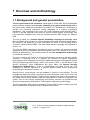
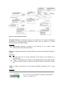
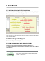
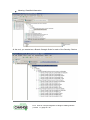
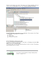
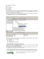
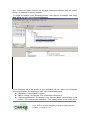
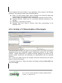
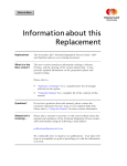
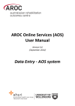
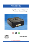
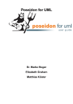
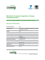
D4.4 Proof of concept integration of design modelling solution Edith Félix, Olivier Delande (THA), Karmel Bekoutou (UNITN) Document information Document Number D4.4 Document Title Framework for integrated documentation of system and assessment results Version Final Status Draft Work Package WP 4 Deliverable Type Prototype Contractual Date of Delivery 31 January 2011 Actual Date of Delivery 28 January 2011 Responsible Unit Thales Contributors THA, UNITN Keyword List System design, Risk Analysis, Security Requirements Dissemination level PU+LIC D4.4. Proof of concept integration of design modelling solution | version 1.1 | page 1 / 59 Document change record Version Date Status Author (Unit) Description 0.1 06.12.10 Draft Thales First draft version (incomplete) 0.2 23.12.10 Draft Thales Second draft version, after 50% review 1.0 31.12.10 Draft Thales First complete version after 50% review 1.1 28.01.11 Final Thales Final version, after 100% review D4.4. Proof of concept integration of design modelling solution | version 1.1 | page 2 / 59 Executive Summary This document describes the D4.4 prototype and presents the Proof of concept integration of design modelling solution. The main purpose of this prototype is to implement a solution for the design modelling solutions developed in the context of Secure Change project, that is to say solutions for security requirements management for long life systems. The focus has been put on the integration of a modelling solution with speciality engineering tooling for security which enables to define and assess the security requirements which must be implemented on the system. Through this prototype, the full Secure Change chain can be demonstrated with a complete tooling which covers system design, risk analysis and security requirements management. Since this prototype has been implemented by Thales for industry purpose, the choice of the tooling selected concerns only the technologies needed for the integration of security engineering with the system/software engineering mainstream. For intellectual properties reasons, the prototype does not present Thales engineering workbench. Since the concepts, methods and principles applicable for security and developed in the context of Secure Change are universal, the integration with a design modelling tool can be very well demonstrated on an Open Source modelling tool supporting UML 2. The choice has been made to use Papyrus UML. The prototype presents Security DSML, a Domain Specific Modelling Language which captures the security concepts of a risk analysis and enables to annotate a model design. The purpose of Security DSML is to provide tools to conduct a risk analysis when designing a system. The outputs of the risk analysis are the security requirements with a strong rationale related to then. These requirements shall be then exported to a Requirement management COTS such as DOORS T-REK. This document presents the prototype, the way to install it, and shows an example of a use case. D4.4. Proof of concept integration of design modelling solution | version 1.1 | page 3 / 59 Index DOCUMENT INFORMATION 1 DOCUMENT CHANGE RECORD 2 EXECUTIVE SUMMARY 3 INDEX 4 1 OVERVIEW AND METHODOLOGY 6 1.1 Background and general presentation 6 1.2 Security DSML metamodel and language 7 1.3 Risk management methodology 1.4 Overall Security Engineering methodology 1.4.1 Towards standard Architecture Frameworks and MDE Engineering methodology 1.4.2 Towards Secure Change Integrated Process 2 11 13 13 14 INTEGRATION BETWEEN THE SECURITY DSML AND PAPYRUS UML 16 2.1 Languages integration 16 2.2 Tool technical integration 17 3 INSTALLATION 18 4 USER MANUAL 21 4.1 Getting started with D4.4 prototype 21 4.2 Model design with Papyrus 21 4.3 Risk management with Security DSML 4.3.1 Preparation step 4.3.2 Activity n°1: Identifying essential elements 4.3.3 Activity n°2: Analysis of the damage scenarios 4.3.4 Activity n°3: Determination of the targets 4.3.5 Activity n°4: Determination of the vulnerabilities 4.3.6 Activity n°5: Analysis of the threats 4.3.7 Activity n°6: Definition of the risks 4.3.8 Activity n°7: Definition of the confinement zone 4.3.9 Activity n°8: Definition of the security objectives D4.4. Proof of concept integration of design modelling solution | version 1.1 | page 4 / 59 21 22 36 38 39 40 41 42 43 44 4.3.10 4.3.11 5 Activity n°9: Definition of the security requirements Activity n°10: Definition of the security solution EXAMPLE 5.1.1 46 47 50 Activities modelling with Papyrus 50 APPENDIX: GLOSSARY 58 REFERENCES 59 D4.4. Proof of concept integration of design modelling solution | version 1.1 | page 5 / 59 1 Overview and methodology 1.1 Background and general presentation The tool presented in this document, developed at Thales after EU-FP6 Modelplex project shall be regarded as a security viewpoint of a system model design tool in the sense where viewpoint is intended in the IEEE 1471 standard as a technology to provide non functional properties tooling integrated to a system engineering workbench. This technology is the focus on French research project Movida (ANR – Call 8). In the last progress of the work for Secure Change project, this security view point has been integrated as a security viewpoint above model design tool Papyrus UML. The tool is based on a Domain Specific Modelling Language for Security called Security DSML which focuses on a risk management process at system design phase. By extension and abusively, the tool itself takes the name of the language and is commonly called Security DSML. The meta-model and the language are presented in section 1.2. The Security DSML language is developed in order to capture the security concepts needed to perform a risk analysis and to manage the risks. It is compliant to the French EBIOS [2] methodology. The overall process of this risk management methodology is presented in section 1.3. The tool is used in the context of a System Engineering process for security specific purposes. A challenge here is to propose an evolution for System Engineering methodologies that integrates the security related requirements. Although the System Security Engineering methodology, which is the focus of WP2, is not the focus of this specific document, some explanations are given about the System Security Engineering Methodology in order to contextualise the usage of the tool. The integration of security concerns in a generic System Model Driven Engineering methodology is described in section 1.4. Starting from a model design, the tool enables to conduct a risk analysis. The risk management phase following it produces Security Objectives, which are in their turn refined in Security Requirements. These security requirements lead to an evolution of the model since Security solutions shall be implemented to complete or transform the model. This is how security engineering and security evolution as studied through Secure Change project shall improve Thales system engineering methodology. The D4.4 prototype (M24 version) includes a Papyrus UML system modelling tool and Security DSML both integrated under an Eclipse environment. D4.4. Proof of concept integration of design modelling solution | version 1.1 | page 6 / 59 Figure 1 Scope of the prototype 1.2 Security DSML metamodel and language Security DSML is the language developed to capture the Security risk analysis concepts. The following schema shows the Security DSML meta-model: The meta-model presented below is a simplified version of the meta-model where the meta-classes related to the general concepts and scales have been removed. The meta-classes are represented with boxes and class symbol. The name of the meta-class is written in the first rectangle. The properties of the meta-classes are described in the second rectangle. The properties shown in italic are references to elements of the system model, that is to say elements that are described by means of the system modelling tool. More details about the link between Security DSML and the UML language are described in Chapter 2 section 2.2. All the elements described below are derived from a meta-class Analysis element providing two properties: Name: A name for an instance of the meta-class. Description: A description for an instance of the meta-class. D4.4. Proof of concept integration of design modelling solution | version 1.1 | page 7 / 59 Figure 2 Security DSML metamodel Essential element: An essential element is an element of the system at Business Architecture or Service-oriented Architecture Plans (refer to section 1.4 Overall Security Engineering Methodology) Properties: Represented element: A pointer to the element of the system model represented by the essential element. Damage: A damage expresses the impact related to a risk on the essential elements of system. Properties: Damage total cost: An overall evaluation of the impact of the damage on a Severity scale. Stake: An evaluation of the impact of the damage according to scales specific to different type of stakes, for example, Business, Safety or Human life, Image, etc. Target: A target is one element of the system potentially threaten by one or more threats. Properties: D4.4. Proof of concept integration of design modelling solution | version 1.1 | page 8 / 59 Represented element: A pointer to the element of the system model represented by the target. Doors component PUID: This field can be filled with the PUID of the component corresponding to this target in DOORS T-REK. Security Level: A tag for a needed security level of the target. Vulnerability: A vulnerability is a weakness in a system, system security procedures, internal controls, or implementation that could be exploited. Properties: Vulnerability level: An evaluation of the vulnerability of the target according to a vulnerability scale. Threat: A threat is any circumstance or event with the potential to adversely impact a system through unauthorized access, destruction, disclosure, modification of data, and/or denial of service. Properties: Threat breach strength: An overall evaluation of the impact of the damage on a Severity scale. Occurrence probability: An evaluation of the opportunity of the threat according to an opportunity scale. Threat operator: The agent of the threat. Risk: A risk is a possibility that a particular threat will adversely impact an element of the system architecture by exploiting a particular vulnerability. Properties: Risk level before management: the risk level when the risk is evaluated but not managed. Risk level after management: the risk level when the risk has been managed through security requirements and security solutions. Risk level: A risk level stores the values of the risk according to the dimensions describes by the properties. Properties: Severity risk level: An evaluation of the severity of the risk according to a severity scale. Opportunity risk level: An evaluation of the opportunity of the risk according to an opportunity scale. D4.4. Proof of concept integration of design modelling solution | version 1.1 | page 9 / 59 Risk level: An evaluation of the overall risk level according to an objective security level scale. Risk management: A risk level stores the values of the risk according to the dimensions describes by the properties. Properties: Objective security level: An evaluation of the targeted overall risk level risk according to an objective security level scale. Strategy: Shows the strategy adopted for the risk management, ie acceptation, reduction, transfer, or non-acceptation of the risk. Security objective: A security objective is an expression of the intention to counter identified risks by goals regarding the security of the system, its organisational security policies, its development environment or its operational environment. Properties: Effect: this records the effect kind of the security objective as security management in terms of detection, protection, recovery and response. Objective Security Level: The security level of the security objective according to an objective security level scale. Security requirement: A security requirement is a functional or assurance general specification concerning the system or its environment, dealing with the security mechanisms to be implemented and covering one or more security objectives. Properties: Doors requirement PUID: This field can be filled with the PUID of the corresponding requirement in DOORS T-REK. Required Level: The security level required for the security requirement according to an objective security level scale. Cost for system: An evaluation of the cost of the security requirement for the entire system. Cost per target: An evaluation of the cost of the security requirement for one target. Security solution: This meta-class derives from the Target meta-class. A security solution is a security measure that implements a security requirement. Properties: D4.4. Proof of concept integration of design modelling solution | version 1.1 | page 10 / 59 Represented element: A pointer to the element of the system model represented by the target. Doors component PUID: This field can be filled with the PUID of the component corresponding to this target in DOORS T-REK. Security Level: A tag for a needed security level of the target. Security solution cost: An evaluation of the cost of the security solution for the entire system. 1.3 Risk management methodology The overall process for the risk analysis is compliant to the EBIOS methodology and can be summarized with the following schema. The activities performed are: Identifying essential elements, aka identifying the perimeter of the study Analysis of the damages Determination of the targets Determination of the vulnerabilities Analysis of the threats Definition of the risks Definition of the confinement zones Definition of the Security Objectives Definition of the Security Requirements Definition of the Security Solutions D4.4. Proof of concept integration of design modelling solution | version 1.1 | page 11 / 59 Figure 3 Risk management methodology More details of each steps are given in Chapter 4. D4.4. Proof of concept integration of design modelling solution | version 1.1 | page 12 / 59 1.4 Overall Security Engineering methodology 1.4.1 Towards standard Architecture Frameworks and MDE Engineering methodology This section presents how this methodology and tooling complement a mainstream System/Software Engineering Process. At Business architecture stage, a first version of the end user security requirements is produced. Security damages are analysed and reported. This should concur to define the main constraints of the business architecture by a trade-off analysis with balancing other functional and non-functional constraints. At Service-oriented stage, security damages are refined according to the related system functions. A functional and non-functional analysis for security is performed, which output is a first service-oriented architecture for security. At logical stage, a complete logical risk analysis is performed, leading to a first identification of security objectives and security requirements in order to cover these risks. At physical stage, a new risk analysis is performed, completing the set of the security objectives and security requirements. Consolidation of the whole risk management strategy is needed. A new version of the architecture is reviewed for each stage with additional security solutions. This version is submitted to a new trade-off analysis to balance other functional and non-functional constraints. Figure 4 Architecture framework and security engineering process D4.4. Proof of concept integration of design modelling solution | version 1.1 | page 13 / 59 1.4.2 Towards Secure Change Integrated Process The process described in this section can be understood as a variation of the Integrated Process that is presented in deliverable D2.2. Whereas deliverable D2.2 explains the wider integration of design, testing, verification, risk assessment and requirements engineering, we focus here on design, risk assessment and requirements engineering. The sequence diagram below presents a simplified version of the process. It is inspired by the sequence diagram Figure 11 Sample Change Story of D2.2. The main difference consists of the introduction of human actors who analyze and manually change the models, where the sequence described in D2.2 propagates automatically the changes between the models. Figure 5 Simplified sequence diagram of the security engineering process In the figure above, at first step, the system architect starts modelling the business architecture and the system overall architecture (for example Service Oriented Architecture). The risk manager, at second step, gets the model started by the System Architect, and analyses the risks at business and service level. He updates the risk model which annotates the system model. In order to cover the risks, he defines new security objectives and security requirements, and propagates these requirements to the requirements models. NB: in our model, the concepts of the requirements are included in our risk model, and the propagation is automated between the risk model and the requirements model, as shown in the detailed sequence diagram below. At third step, the requirements engineer then gets the requirements, and assesses them. D4.4. Proof of concept integration of design modelling solution | version 1.1 | page 14 / 59 Once the requirements are accepted, the System Engineer, at fourth step, translates them into solutions, and models the Logical architecture and the Physical architecture. As the system engineer, the security engineer, at fifth step, translates the security requirements into solutions, and changes the Logical architecture and the Physical architecture in order to show the security measures to be implemented. The sixth step is the overall mitigation and assessment of the system model by the system architect. In fact, the risk analysis must be conducted also on the Logical architecture and Physical architecture, since these layers bring new details on the solutions to be implemented, and therefore and the vulnerabilities brought by these solutions. The sequence diagram below shows the detailed version of the process. Figure 6 Detailed sequence diagram of the security engineering process D4.4. Proof of concept integration of design modelling solution | version 1.1 | page 15 / 59 2 Integration between the Security DSML and Papyrus UML This chapter presents the integration of Thales' own security modeling tool, the Security DSML, with a generic model design workbench. The Security DSML is dedicated to risk analysis and security concerns, both as a language and as tool, and is intended to serve as a security viewpoint in a more general engineering workbench. It was designed to capture security concepts relevant to the risk analysis, including risks, targets, objectives and requirements, and supports standard methodologies such as EBIOS. Those methodologies are generic and not tied to particular practices in main engineering, which is reflected in the fact that the Security DSML can be coupled to a number of tools supporting system design. In the context of Secure Change, Thales developed an integration between the Security DSML and Papyrus UML, an open source and popular UML 2 modeling tool, using their common EMF foundations. 2.1 Languages integration In a risk analysis, it is necessary to refer to the system under consideration. In our approach centered around modeling languages, two perimeters are identified: the risk analysis, which is performed using the Security DSML; the system design, which is performed (in this case) using Papyrus UML. The risk analysis refers to the system design through specific model elements. In our conceptual model, the risk analysis interacts with the system around two notions: essential elements, which are functions of the system that may be subject to damage; targets, which are system components realizing those functions, and may have vulnerabilities and threats. Some of the concepts of the Security DSML reference system elements. In the D4.4 prototype, since the Security DSML is integrated with Papyrus UML, the system elements are described with the UML language. Therefore, some of the Security DSML meta-classes have references to UML classes. In security DSML, only a few The meta-classes EssentialElement, Target and Security Solutions. Their instances represent the corresponding notions introduced in the previous section. EssentialElement has a reference representedElement of type BehavioredClassifier that refers to the UML system element represented by this essential element; Target has a reference representedElement of type Classifier that refers to the UML system element represented by this target. D4.4. Proof of concept integration of design modelling solution | version 1.1 | page 16 / 59 Security solution refines the class Target. It has a reference representedElement of type Classifier that refers to the UML system element represented by this target. 2.2 Tool technical integration The technical integration of the Security DSML and Papyrus UML is made possible by the fact that the languages of both tools are defined as Ecore meta-models. We used this common foundation as an easy way to define a loose coupling. The EMF (Eclipse Modeling Framework) consists of a set of libraries and tools that allows the manipulation of models and the generation of code to quickly develop modeling tools. EMF itself sits on top of the Eclipse platform and inherits its modular structure (based on plugins) and portability (using the Java programming language). One of the key features of the modular structure of Eclipse is the ability to run several plugins within a single instance of Eclipse. This allowed us to build a prototype integrating the Thales Security DSML and Papyrus UML. The prototype of the Thales DSML was developed in EMF in several steps: A meta-model consisting of the concepts was defined in Ecore; The concepts that interface with the system model were augmented with references to UML elements, thus representing the link between the two models, as described in the above section. The prototype of the DSML was produced using EMF code generation facilities. The tool was completed by plugging the DSML and Papyrus UML together. As a result, Security DSML is an update site of Papyrus UML Eclipse product. The installation of these tools is described in next chapter. D4.4. Proof of concept integration of design modelling solution | version 1.1 | page 17 / 59 3 Installation This chapter describes the installation step for the prototype. First install a Papyrus UML (current version is Then download the Security DSML update site as a zip file in a given repository (for example D:\Programs\PapyrusDSML\Update site DSML) Then you need to update your Papyrus version with the Security DSML Update site. Execute your Papyrus.exe file to launch Papyrus. In the Help Menu, click on Install New Software. An Install window prompts. Uncheck Group items by category box. Click on the Add button and browse for the repository of the Security DSML update site. D4.4. Proof of concept integration of design modelling solution | version 1.1 | page 18 / 59 Click on OK The name of the Risk Analysis update site appears on the main frame of the Install window. Check the box corresponding to the new update site. Click Finish to install the update site. The Security DSML update site is now installed under the name Riskanalysis. D4.4. Proof of concept integration of design modelling solution | version 1.1 | page 19 / 59 D4.4. Proof of concept integration of design modelling solution | version 1.1 | page 20 / 59 4 User Manual 4.1 Getting started with D4.4 prototype When you have clicked on the Papyrus.exe file, a Papyrus instance starts. It shows the same menus and frames as a standard Papyrus except there is an additional tab for Risk analysis in the central frame showed by the red arrow. When you click on the Risk analysis tab, the menus change to show the Risk analysis ones. (See figure below) 4.2 Model design with Papyrus Please refer to Papyrus User Guide [6] 4.3 Risk management with Security DSML Please refer to the overall Risk management methodology paragraph 1.2 For a better understanding of Risk management methodology, please refer to EBIOS methodology [2]. D4.4. Proof of concept integration of design modelling solution | version 1.1 | page 21 / 59 4.3.1 Preparation step The objective of this step is to define, or select if it already pre-exists, a referential of security metrics and scales.. 4.3.1.1 Initialisation of a study The first preparation step is to initialize a study that will link all the data used to go through the security engineering process for one given system at a given time of its lifecycle. To create the instances of the risk analysis concepts, you can organise them in separate Packages. To create a Package, click right on the initial Package. The list of the available security concepts appears. Select Package. In order to link your security concepts to the model elements of the model developed under Papyrus, you need to load the System Model Resources into your Risk analysis study. Go to the root of the risk analysis tree. Click right on it and select Load Resource. A Load Resource box appears. Select Browse workspace and select the uml model you have created with the Papyrus software. D4.4. Proof of concept integration of design modelling solution | version 1.1 | page 22 / 59 4.3.1.2 Definition of security metrics and their scale The following metrics shall be then set at the beginning of each study. Re-use of metrics shall be performed from one study to the other. The metrics to be set are the following: Security criteria vector: the security criteria used for the study, ie at least confidentiality, availability, integrity. Breach strength scale by security criterion: a scale to evaluate the strength of a threat and the misbehavior in terms of security criteria caused by the threat on the system. Stake types vector: this defines the types of stakes on which the impact of the damages are evaluated. Damage Cost scale by stake type: a scale to evaluate the impact of the damage, per stake type. Vulnerability scale: a scale to evaluate the level of vulnerability of a target. Threat probability scale: a scale to evaluate the opportunity of the occurrence of a threat. Severity scale: a scale to evaluate the severity of a risk. Opportunity scale: a scale to evaluate the opportunity of a risk. D4.4. Proof of concept integration of design modelling solution | version 1.1 | page 23 / 59 Objective security level scale: a scale to express the targeted security level of a risk Risk Management strategy: an expression of the security management strategy adopted, in term of acceptation, reduction, transfer, non acceptation of the risk. 4.3.1.2.1 Definition of the security criteria vector Relevant security criteria for the study are selected, and arranged in a security criteria vector. The Security criteria vector is usually composed with: Availability Confidentiality Integrity other To create an instance of Breach strength scale by security criterion, click right on a Package, and select New Child, and then select Breach strength scale by security criterion. D4.4. Proof of concept integration of design modelling solution | version 1.1 | page 24 / 59 Give a name to the scale you have created. Go to the Properties tab at the bottom of your application. In the value field of the Name property, type the name of the security criterion you want to describe, for example Confidentiality. Create as many scales as the number of security criteria you want to describe. 4.3.1.2.2 Definition of the Breach strength scale by security criterion Breach strength scale by security criterion is an array defining the value on a 5 level scale (from 0=not relevant to 4=high) of characteristic breach for each of the security criteria. The scale might be set after the analysis of the needs through the different business departments of the organization which will enlighten the most relevant damages. D4.4. Proof of concept integration of design modelling solution | version 1.1 | page 25 / 59 For example: Security Criteria Availability Confidentiality Integrity 0 Not relevant Not relevant Not relevant 1 Less than 5 seconds Data is kept confidential disruption Integrity is guarantied 2 1 to 59 disruption Data is lightly and partially lost 3 1 hour to 23 hours disruption 4 1 day disruption minutes Data is divulgated within the organisation or Data is divulgated among partners more Data is made Public 6 hours of data definitively lost Data is totally lost For each scale, create now the steps of the scale. Click right on the Breach Strength Scale By Security Criterion you created, and select New Child, and then select Breach strength scale by security criterion. In the Properties tab at the bottom of your application, fill the values of the Breach Strength Scale Step properties, for example: Value: 4 Name: Critical D4.4. Proof of concept integration of design modelling solution | version 1.1 | page 26 / 59 Meaning: Classified information At the end, you created as a Breach Strength Scale for each of the Security Criterion D4.4. Proof of concept integration of design modelling solution | version 1.1 | page 27 / 59 you needed. 4.3.1.2.3 Definition of the stake types vector The stake types vector constitutes a reduced list of stakes relevant for the organization and the context. The damages costs will be evaluated according to these stakes. For example, for an organization, stakes can be budget, image, health safety. To create an instance of Damage Cost scale by stake type, click right on a Package, and select New Child, and then select Damage Cost Scale by Stake Type. Give a name to the scale you have created. Go to the Properties tab at the bottom of your application. In the value field of the Name property, type the name of the security criterion you want to describe, for example Safety aka Human life. Create as many scales as the number of stakes you want to describe. 4.3.1.2.4 Definition of damage cost scale by stake type The Damage Cost scale by stake type is an array expressing the value on a 5 level scale (from 0=not relevant to 4=high) of a damage according to one of the stakes. After the analysis of the needs through the different business departments of the organization, arbitration should be done in order to harmonize the scales of each component of the stake vector. For example: Cost of the damages Budget Image Health safety 0 Not relevant Not relevant Not relevant 1 < 1.000 € Profesionnal and Secondary effects or light Corporative communication injury 2 < 25.000 € Mass Media Serious injuries 3 < 500.000 € Strong measures must accompagn media campaign Threat to human life 4 > 10.000.000 € General crisis Over 10 human deaths For each scale, create now the steps of the scale. Click right on the Damage Cost Scale By Stake you created, and select New Child, and then select Damage Cost Scale By Stake Step. D4.4. Proof of concept integration of design modelling solution | version 1.1 | page 28 / 59 In the Properties tab at the bottom of your application, fill the values of the Damage Cost Scale By Stake Step properties, for example: Value: 2 Name: Medium Meaning: Serious Injuries 4.3.1.2.5 Definition of the vulnerability scale To create an instance of Vulnerability scale, click right on a Package, and select New Child, and then select Vulnerability scale. The vulnerability scale is an array defining the value of the weakness of a target together with the ease to exploit it. The vulnerability scale is defined from 0 to 4, where: 0 means “not relevant”; 1 is “low”; 2 is “medium”; 3 is “high”; 4 is “critical”. The system security risk manager can qualify the meaning of this scale according to the context of the study, for example, “Low” meaning hardened with a complete checklist and cryptographic means, etc. Create now the steps of the scale. Click right on the Vulnerability scale you created, and select New Child, and then select Vulnerability Scale Step. D4.4. Proof of concept integration of design modelling solution | version 1.1 | page 29 / 59 In the Properties tab at the bottom of your application, fill the values of the Vulnerability Scale Step properties, for example: Value: 1 Name: Low Meaning: Costs more than 10.000 € to penetrate 4.3.1.2.6 Definition of the Threat probability scale To create an instance of Threat probability scale, click right on a Package, and select New Child, and then select Threat probability scale. The threat probability scale is an array defining the value of the probability of occurrence of a threat. The threat probability scale is defined from 0 to 4, where: 0 means “not relevant”; 1 is “low”; 2 is “medium”; 3 is “high”; 4 is “critical”. The system security risk manager can qualify the meaning of this scale according to the context of the study, for example, “Low” meaning hardened with a complete checklist and cryptographic means, etc. D4.4. Proof of concept integration of design modelling solution | version 1.1 | page 30 / 59 Create now the steps of the scale. Click right on the Threat probability scale you created, and select New Child, and then select Threat probability Scale Step. In the Properties tab at the bottom of your application, fill the values of the Threat Probability Scale Step properties, for example: Value: 3 Name: High Meaning: Every month 4.3.1.2.7 Definition of the severity scale To create an instance of Severity scale, click right on a Package, and select New Child, and then select Severity scale. The severity scale is an array defining the severity of a risk if it occurs. The severity scale is defined from 0 to 4, where: D4.4. Proof of concept integration of design modelling solution | version 1.1 | page 31 / 59 0 means “not relevant”; 1 is “low”; 2 is “medium”; 3 is “high”; 4 is “critical”. The system security risk manager can qualify the meaning of this scale according to the context of the study, for example, “Low” meaning a light degradation of the service without much impact on the organization, etc. Create now the steps of the scale. Click right on the Severity scale you created, and select New Child, and then select Severity Scale Step. In the Properties tab at the bottom of your application, fill the values of the Severity Scale Step properties, for example: Value: 4 Name: Critical Meaning: Over 1.000.000 € 4.3.1.2.8 Definition of the opportunity scale To create an instance of Opportunity scale, click right on a Package, and select New Child, and then select Opportunity scale. The opportunity scale is an array defining the value of the chances for a risk to occur. The opportunity scale is defined from 0 to 4, where: D4.4. Proof of concept integration of design modelling solution | version 1.1 | page 32 / 59 0 means “not relevant”; 1 is “low”; 2 is “medium”; 3 is “high”; 4 is “imminent”. The system security risk manager can qualify the meaning of this scale according to the context of the study, for example, “Low” meaning one time per year or 1/1.000.000, etc. Create now the steps of the scale. Click right on the Opportunity scale you created, and select New Child, and then select Opportunity Scale Step. In the Properties tab at the bottom of your application, fill the values of the Opportunity Scale Step properties, for example: Value: 3 Name: High Meaning: Every month D4.4. Proof of concept integration of design modelling solution | version 1.1 | page 33 / 59 4.3.1.2.9 Definition of the objective security level scale To create an instance of Objective security level scale, click right on a Package, and select New Child, and then select Objective Security Level scale. The objective security level scale scores the level of security that is targeted on a given perimeter. The security level scale is defined from 0 to 4, where: 0 means “not relevant”; 1 is “low”; 2 is “medium”; 3 is “high”; 4 is “critical”. The two dimensions of severity and opportunity for a risk quantification are projected on a single dimension called security objective level. A rule is chosen at the beginning of the study for the correspondence between a (severity, opportunity) vector and its corresponding security level. Create now the steps of the scale. Click right on the Opportunity scale you created, and select New Child, and then select Opportunity Scale Step. D4.4. Proof of concept integration of design modelling solution | version 1.1 | page 34 / 59 In the Properties tab at the bottom of your application, fill the values of the Objective Security Level Scale Step properties, for example: Value: 4 Name: Critical Meaning: Severity is critical, Opportunity is medium or higher. 4.3.1.2.10 Definition of the Risk Management strategy To create an instance of Risk Management strategy, click right on a Package, and select New Child, and then select Risk Management strategy. The Risk Management strategy lists the different risk management strategies. The risk management strategies have numbers from 0 to 4. Typically, it is a pre-defined array of Booleans, showing what management strategy will be applied to the risk: Acceptable Reduction Transfer Unacceptable Create now the steps of the scale. Click right on the Risk Management strategy you created, and select New Child, and then select Risk Management strategy Step. D4.4. Proof of concept integration of design modelling solution | version 1.1 | page 35 / 59 In the Properties tab at the bottom of your application, fill the values of the Risk Management strategy Step properties, for example: Value: 3 Name: Transfer Meaning: Severity is critical, Opportunity is medium or higher. NB: A new Package can be created as a parent to the instances of the next security concepts of the risk analysis. To create a package, refer to 4.3.1.3 Initialisation of a study. 4.3.2 Activity n°1: Identifying essential elements This activity takes as input the functional part of the system architecture elaborated during the mainstream system engineering process, by the system architect. The functional architecture of the system is analysed by the system security risk manager in order to identify, within the functions and data of this system architecture, the essential elements that need protection. These essential elements define the scope for the system security analysis. D4.4. Proof of concept integration of design modelling solution | version 1.1 | page 36 / 59 As a 1st step, the system security risk manager references elements from the system design, for example an activity diagram. To create an instance of an Essential element, click right on a Package, and select New Child, and then select Essential Element. In the Properties tab at the bottom of your application, fill the values of the Essential Element properties. The meaning of each value is described below: Description: A description if needed Name: A name, for example: TCC computes the Sequence Represented Element: The Activity of the Papyrus Model corresponding to the activity “TCC computes the Sequence”. This activity shows in the combo-box if D4.4. Proof of concept integration of design modelling solution | version 1.1 | page 37 / 59 the Papyrus model has been correctly uploaded as show in 4.3.1.3 Initialisation of a study. Supporting Element; Will be filled at Activity n°3 Determination of the Targets. Contains the list of the targets which support the Essential Element. 4.3.3 Activity n°2: Analysis of the damage scenarios This activity requires the involvement of the system acquirer. It consists of imagining damage scenarios which could occur to the system and hurt it. A damage scenario is a composed vector of vectors binding several security metrics such as breach strength conditions and damage cost of a security breach situation. The system acquirer can create the damage scenario, write a short description of it, set the vector of the stakes types, evaluate the damage cost according to damage cost scale, define the essential elements it applies to and describe the damage condition of the damage scenario. To create an instance of a Damage, click right on a Package, and select New Child, and then select Damage. D4.4. Proof of concept integration of design modelling solution | version 1.1 | page 38 / 59 In the Properties tab at the bottom of your application, fill the values of the Damage properties. The meaning of each value is described below: Stake: For each relevant stake, select a Damage Cost Scale By Stake Step corresponding to the adequate value on the scale. Name: A name, for example: Loss of information provisioning from/to ATCOs. Impacted Element: Select the list of essential elements impacted by this damage. Description: A description if needed Damage Total Cost: Select a Severity Scale Step corresponding to the adequate value. 4.3.4 Activity n°3: Determination of the targets This activity takes as input the logical or the physical part of the system architecture elaborated during the mainstream system engineering process, by the system architect. Targets determination is performed through analysing the entities of the physical system architecture and identifying the dependencies with the essential elements. As a 1st step, the system security risk manager references elements from the system logical or physical architecture. To create an instance of a Target, click right on a Package, and select New Child, and then select Target. D4.4. Proof of concept integration of design modelling solution | version 1.1 | page 39 / 59 In the Properties tab at the bottom of your application, fill the values of the Target properties. The meaning of each value is described below: Security Level: If needed, this field enables to tag the target with a security level which indicates a confinement zone. Represented Element: Select the instance of the Papyrus Model represented by this target. These instances can be activities of an activity diagram, components of a component diagram, etc. Name: A name, for example: TCC computes the sequence. Doors component PUID: This field enables to import the Product UID of the component as defined in Doors. Description: A description if needed nd As a 2 step, when all targets have been created, the system security risk manager can link each essential element to the targets which support it. Refer to Activity 1: Identifying Essential Elements, and fill field Supporting Element of the Essential Element Properties. 4.3.5 Activity n°4: Determination of the vulnerabilities This activity consists in assigning vulnerabilities to the previously identified targets. This step is optional. As 1st step, the system security risk manager can perform the vulnerability analysis. He will describe the relevant vulnerabilities and the target which they apply to. As 2nd step, the system security risk manager can perform the vulnerability assessment. He will assess the vulnerability level of each vulnerability. To create an instance of a Vulnerability, click right on a Package, and select New D4.4. Proof of concept integration of design modelling solution | version 1.1 | page 40 / 59 Child, and then select Vulnerability. In the Properties tab at the bottom of your application, fill the values of the Vulnerability properties. The meaning of each value is described below: Description: A description if needed Name: A name, for example: TCC computes the sequence. Value: Select a Vulnerability Scale Step corresponding to the adequate value. 4.3.6 Activity n°5: Analysis of the threats The activity consists in analysing the threats and their targets. As 1st step, the system security risk manager can perform the threat analysis. He will describe the relevant threats and the target which they apply to. Threats types are associated with a breach strength which is valued for each security criterion according to the breach strength scale. As 2nd step, the system security risk manager can start the threat assessment. He will review the threat probability associated with the threat type and modify it according to the context if necessary. To create an instance of a Threat, click right on a Package, and select New Child, and then select Threat. In the Properties tab at the bottom of your application, fill the values of the Threat properties. The meaning of each value is described below: Description: A description if needed Name: A name, for example: TCC overload. Occurrence Probability: Select a Threat Probability Scale Step corresponding to the adequate value. Target Perimeter: Select the list of the targets on which apply the threat. Threat Breach Strength: for each relevant Security Criterion, select a Breach Strength Scale Step corresponding to the adequate value on the scale. Threat Operator: if needed, select the agent of the Threat. D4.4. Proof of concept integration of design modelling solution | version 1.1 | page 41 / 59 4.3.7 Activity n°6: Definition of the risks Risks occur when there is a potential of exploitation by a threat of vulnerability on a target. Risks are expressed at both functional and architecture plans of the system architecture, respectively by means of the damages and of the threats. As a 1st step, the system security risk manager can perform the risk analysis. He will describe the relevant risks. For each risk, he can review the damage associated to it, and the essential elements it applies to. He can also review the threats associated to it, and the targets it applies to. He can assign a name and a short description to each risk. To create an instance of a Risk, click right on a Package, and select New Child, and then select Risk. In the Properties tab at the bottom of your application, fill the values of the Risk properties. The meaning of each value is described below: Damage: Select the damage to which the risk corresponds. Description: A description if needed Name: A name, for example: A12. Risk Level After Management: This field is filled at the end of the risk analysis when countermeasures or security solutions have been added to cover the risk. Risk Level Before Management: This field is filled in the next step. Threat: Select the threat to which the risk corresponds. Risk Management: This field is filled during Activity 7: Definition of the Confinement Zone. As a 2nd step, the system security risk manager can perform the risk assessment. He will set the risk opportunity before management according to the related threat probability value, and he will set the risk severity before management according to the Total cost of the Damage. The risk level is a unique value which synthesizes the two dimensions of severity and opportunity mentioned above, according to the Security Objective Level scale. D4.4. Proof of concept integration of design modelling solution | version 1.1 | page 42 / 59 NB: A new Package can be created as a parent to the instances of the following security concepts of the risk analysis: Risk Level, Risk Management, Security Objective Effect Kind. To create a package, refer to 4.3.1.3 Initialisation of a study. To create an instance of a Risk Level, click right on a Package, and select New Child, and then select Risk Level. In the Properties tab at the bottom of your application, fill the values of the Risk Level properties. The meaning of each value is described below: Name: A name, for example A12 before management CRITICAL Risk Level: select an Objective Security Level Step corresponding to the adequate value on the scale. Opportunity Level: select an Opportunity Level Step corresponding to the adequate value on the scale. Severity Level: select a Severity Level Step corresponding to the adequate value on the scale. 4.3.8 Activity n°7: Definition of the confinement zone At this stage of the study, system security risk managers have got a list of valuated risks. They should now define a risk management strategy and confinement zones that set an acceptable risk level for the zone. Confinement zone enables the system security risk manager to define a perimeter of essential elements and targets where a given security objective level is targeted as a goal. The security objectives usually consist of an expression of the level of the system acquirer's will to cover the risks. As a 1st step, the system security risk manager defines the targeted Objective Security Level for each risk according to the Objective Security Level scale. As a 2nd step, the system security risk manager sets for each risk the risk management strategy. The risk management strategy is a predefined list of Booleans showing if the risk management should contribute to Detection, Protection, Response or Recovery. Both of these steps are captured by the Risk Management Concept. To create an instance of a Risk Management, click right on a Package, and select New Child, and then select Risk Management. D4.4. Proof of concept integration of design modelling solution | version 1.1 | page 43 / 59 In the Properties tab at the bottom of your application, fill the values of the Risk Level properties. The meaning of each value is described below: Name: A name, for example B17 Risk Management Objective Security Level: select an Objective Security Level Step corresponding to the adequate value on the scale. Strategy: select a Risk Management strategy step corresponding to the adequate management strategy. After the Risk Management has been created, go back to the related Risk, click on the Risk Management field and select the corresponding Risk Management of the risk (refer to Activity 6: Definition of the risks). As a 3rd step, the system security risk manager can create a confinement zone. For each target of the confinement zone, he sets the security level to the Objective security level that is targeted for the confinement zone. Refer to Activity 3: Determination of the Targets, field Security Level. 4.3.9 Activity n°8: Definition of the security objectives The security objectives must cover all the risks that it has been decided to cover, taking into account the assumptions, security rules and various context elements (especially the constraints and issues at stake). They must be consistent with the operational objective or declared "product" objective of the target system and any knowledge of its physical environment. The security objectives usually consist of the expression of the system acquirer's will to cover the risks, without specifying the solutions for achieving this. They will therefore constitute a complete set of directions, which remains open in terms of the solutions to adopt and is perfectly adapted to the issues facing the system. The purpose of the security objectives determined above is to counter or minimise the risks affecting the target system. The system security risk manager conducting the study must now check that they are necessary and sufficient for covering all the identified risks and assumptions. D4.4. Proof of concept integration of design modelling solution | version 1.1 | page 44 / 59 As a 1st step, the system security risk manager can define the objectives to cover the risks. For each objective, he can enter its description, the risk it applies to, the objective security level, and its effect kind. To create an instance of a Security Objective, click right on a Package, and select New Child, and then select Security Objective. In the Properties tab at the bottom of your application, fill the values of the Security Objective properties. The meaning of each value is described below: Objective Security Level: select an Objective Security Level Step corresponding to the adequate value on the scale. Name: A name, for example O1-A12 Effect:This field is filled during the next step. Description: A description if needed. Covered risk: select the list of the risks covered by the Security Objective. As a 2nd step, the security risk manager describes the security objective effect kind. The security objective effect kind is a pre-defined array of Booleans, showing if the D4.4. Proof of concept integration of design modelling solution | version 1.1 | page 45 / 59 security objective will contribute to the following risk management effect kind: Detection Protection Response Recovery To create an instance of a Security Objective Effect Kind, click right on a Package, and select New Child, and then select Security Objective Effect Kind. In the Properties tab at the bottom of your application, fill the values of the Security Objective Effect Kind properties. The meaning of each value is described below: Name: A name, for example O1 Detection: Select true if the security objective contributes to detection of the threat. Protection: Select true if the security objective contributes to protection of the target. Recovery: Select true if the security objective contributes to recovery of essential elements and/or targets. Response: Select true if the security objective contributes to response to the threat. As a 3rd step, the system security risk manager must verify the way the security objectives cover the risks. As a 4th step, the system security risk manager will verify the coherence between the objective security level of the Security objective and the targeted objective security level as defined in the Risk management of the risk it applies to. 4.3.10 Activity n°9: requirements Definition of the security The purpose of this activity is to determine how to achieve the security objectives, i.e. how to treat the risks affecting the system. This requires determining the security requirements on the system. Coverage of the security objectives by the functional and assurance requirements must be justified by a rationale indicating their necessity and adequacy. As a 1st step, the system security risk manager defines security requirements to cover each security objective. For each requirement, he defines a description and selects the security objectives it applies to. He can add the cost of the requirement per target and the cost of the requirement for the whole system. To create an instance of a Security Requirement, click right on a Package, and select New Child, and then select Security Requirement. D4.4. Proof of concept integration of design modelling solution | version 1.1 | page 46 / 59 In the Properties tab at the bottom of your application, fill the values of the Security Requirement properties. The meaning of each value is described below: Specified Objective: select the Security Objective which is refined by this security requirement. Security Solution: This field will be filled after the security solution of this security requirement has been defined at Activity 10: Definition of the Security Solutions. Required Level: This field should be set at the same value of the Objective Security Level field of the corresponding Security Objective. Name: A name, for example Req 01 (O1-A12) Doors Requirement PUID: This field enables to import the PUID of the requirement as defined in Door. Description: A description if needed. Cost per Target: This field enables to add an estimated cost per target. Cost for System: field enables to add an estimated cost for the entire system. As a 2nd step, the system security risk manager must verify the way the security requirements cover security objectives. As a 3rd step, the system security risk manager will verify the coherence between the objective security level of the requirements and the security level of the Objective it covers. He shall set the required objective security level according to the objective security level of the Objective it covers. 4.3.11 Activity n°10: Definition of the security solution The purpose of this activity is to translate Security Requirements into security solutions as a feedback on the model design. The output architecture will be then proposed for evaluation to the mainstream engineering process for a trade-off analysis between other speciality engineering proposals. D4.4. Proof of concept integration of design modelling solution | version 1.1 | page 47 / 59 As a 1st step, the system security risk manager defines security solutions to cover the security requirement. For each solution, he defines a description, and selects the security requirement it applies to. He can also refer to existing targets on which the security solution shall be deployed. He can add the cost of the security solution for the system. He can also reference an ISO Theme (for example a section of ISO 27002) it contributes in order to ease the management of the best practices. To create an instance of a Security Solution, click right on a Package, and select New Child, and then select Security Solution. In the Properties tab at the bottom of your application, fill the values of the Security Solution properties. The meaning of each value is described below: Applying Targets: select the Targets on which applies this security solution. Description: A description if needed. Doors component PUID: This field enables to import the Product UID of the component as defined in Doors. Name: A name, for example RBAC Related ISO Theme: A reference to a section of ISO 27002 can be entered here. Represented Element: Select the instance of the Papyrus Model represented by this target. These instances can be activities of an activity diagram, components of a component diagram, etc. Security Level: If needed, this field enables to tag the target with a security level which indicates a confinement zone. Security Solution Cost: This field enables to add an estimated cost of the security solution. As a 2nd step, after the Security Solution has been created, go back to the related Security Requirement, click on the Security Solution field and select the corresponding Security solution of the Security Requirement (refer to Activity 9: Definition of the security requirements). D4.4. Proof of concept integration of design modelling solution | version 1.1 | page 48 / 59 As a 3rd step, the system security risk manager enters the new value of the risk after the implementation of the security risk solution. For the risk covered by the security solution, create a new instance of a Risk Level as described in the 2nd step of Activity 6: Definition of the risks. Gives a name such as Name: A name, for example A12 after management MEDIUM D4.4. Proof of concept integration of design modelling solution | version 1.1 | page 49 / 59 5 Example 5.1.1 Activities modelling with Papyrus Activity diagrams are used under Papyrus to describe the activities of the ATM scenario accomplished by different roles of Air Traffic Controllers such as Tactical Controller (TCC), Planning Controller (PLC). After the introduction of the Arrival Manager (AMAN) automatic computation engine, two roles are added, the AMAN and the Sequence Manager (SQM). Before the introduction of the AMAN, the activities are the following: PLC monitors the traffic: PLC monitors traffic on his/her Controller Working Position. PLC detects the need for a change in Sequence: by means of the sub-activities performed in parallel such as: o Read Radar Tracks o Read A/C Data o Apply Separation Criteria1 PLC detects the need for a change in the Sequence. PLC asks for a Sequence Modification After having detected the need for a change in the Sequence, PLC asks TCC for a Sequence modification. TCC computes the Sequence: by means of the sub-activities performed in parallel such as: o Read Radar Tracks o Read A/C Data o Apply Separation Criteria2 TCC computes the aircraft sequence. TCC modifies the Sequence: Separation criteria shall be applied by Air Traffic Controllers in order to guaranty a safe separation of the aircraft in a sequence of arrivals. 1 Separation criteria shall be applied by Air Traffic Controllers in order to guaranty a safe separation of the aircraft in a sequence of arrivals. 2 D4.4. Proof of concept integration of design modelling solution | version 1.1 | page 50 / 59 by means of the sub-activities performed in parallel such as: o Read Radar Tracks o Read A/C Data o Apply Separation Criteria TCC modifies the aircraft sequence. The following diagram shows the activity diagram in Papyrus, with the PLC activities in yellow and the TCC activities in pink. 5.1.1.1 Perimeter of the study / Identify Essential elements The Security DSML is used over Papyrus design tool in order to perform a risk analysis. The perimeter considered for the risk analysis consists on the activity diagrams drawn with Papyrus. The activities considered are the following: PLC monitors the traffic PLC detects a need for a change in the Sequence PLC asks for a Sequence modification TCC computes the Sequence D4.4. Proof of concept integration of design modelling solution | version 1.1 | page 51 / 59 TCC modifies the Sequence The risk analysis performed with WP5 with the domain experts from Deep Blue provides relevant inputs to analyse these activities. 5.1.1.2 Analysis of the Damages Possible damages are identified in relation with the activities above, with a total cost of the damage level. For each damage of the list below, the impacted activities are indicated. Loss of information provisioning to/from ATCOs: Critical o TCC computes the Sequence Failure in the provisioning of correct arrival information: High o TCC modifies the Sequence Failure in the provisioning of optimal arrival information: Medium o PLC detects a need for a change in the Sequence o PLC asks for a Sequence modification o TCC computes the Sequence o TCC modifies the Sequence 5.1.1.3 Determination of the targets The targets are the activities. 5.1.1.4 Determination of the Vulnerabilities Vulnerabilities identified on the different actors and activities are the following. For each vulnerability of the list below, the related activities are indicated. High coordination workload o PLC detects a need for a change in the Sequence o TCC computes the Sequence Non-compliance of ATCO with procedures o PLC detects a need for a change in the Sequence o TCC computes the Sequence Stress, concentration problems, health conditions, etc. o TCC computes the Sequence D4.4. Proof of concept integration of design modelling solution | version 1.1 | page 52 / 59 Lack of routines for avoiding multitasking o TCC computes the Sequence Overload of traffic; high workload o TCC modifies the Sequence 5.1.1.5 Analysis of the Threats Threats are listed below with a opportunity level. For each threat, the related activities are indicated, as well as the breach strength. ATCO mistake: High o PLC detects a need for a change in the Sequence o TCC computes the Sequence Breach Strength: Availability-Medium; Integrity-High Non-compliance of ATCO with procedures: Low o PLC detects a need for a change in the Sequence o TCC computes the Sequence Breach Strength: Availability-Medium; Integrity-High TCC unavailability: Low o TCC computes the Sequence Breach Strength: Availability-Critical; Integrity-Critical TCC overloaded: High o TCC computes the Sequence Breach Strength: Availability-Critical; Integrity-High ATCO fails to manually update the system: Medium o TCC modifies the Sequence Breach Strength: Availability-High; Integrity-High 5.1.1.6 Definition of the Risks The following risks are identified, with Severity and Opportunity and overall risk level. For each risk, the related damages and threats are indicated. In order to provide a better reading, the related activities are also re-called. B17 Failure in the provisioning of correct or optimal arrival information (stabilization or coordination of sequence) due to ATCO mistakes D4.4. Proof of concept integration of design modelling solution | version 1.1 | page 53 / 59 o Severity: High, Opportunity: High, overall risk level: High o Damage: Failure in the provisioning of correct or optimal arrival information ; o Threat : ATCO mistake o Activity: PLC detects a need for a change in the Sequence ; TCC computes the Sequence; B16 Failure in the provisioning of correct or optimal arrival information due to non-compliance of ATCO with procedures o Severity: High , Opportunity: Low, overall risk level before management: Medium o Damage : Failure in the provisioning of correct or optimal arrival information; o Threat : Non-compliance of ATCO with procedures o Activity : PLC detects a need for a change in the Sequence; TCC computes the Sequence ; B13 Tactical Controller (TCC) becomes unavailable during arrival management process due to his/her physical/mental condition o Severity: Critical , Opportunity: Low, overall risk level management: High o Damage: Loss of information provisioning to/from ATCOs; o Threat: TCC unavailability o Activity: TCC computes the Sequence; before A12 TCC fails to provide arrival information to all relevant recipients simultaneously due to communication overload (radio with A/C, voice with PLC) o Severity: Critical , Opportunity: High, overall risk level before management: Critical o Damage: Loss of information provisioning to/from ATCOs; o Threat: TCC overload o Activity TCC computes the Sequence; B18 ATCO fails to manually update the system which leads to the provisioning of inconsistent data o Severity: Medium , Opportunity: Medium, overall risk level before management: Medium D4.4. Proof of concept integration of design modelling solution | version 1.1 | page 54 / 59 o ; Damage: Failure in the provisioning of correct arrival information; o Threat: ATCO fails to manually update the system o Activity: TCC modifies the Sequence 5.1.1.7 Definition of the confinement zone In the context of this risk analysis performed over activities of a process, this activity corresponds into deciding what level of risk is considered as unacceptable and therefore the type of risk management shall be put in place. In the domain of Air traffic control, risks with risk level from critical to medium shall be managed. The goal in this first study is to reduce the risks below a medium objective risk level. 5.1.1.8 Definition of the Security Objectives In order to cover the risks defined through the Risk analysis process, the following additional Security Objectives are defined. For each Security Objective, the objective security level and the related risks are indicated: O1 The Sequence shall be computed automatically by an Arrival Manager system: Medium o B17 Failure in the provisioning of correct or optimal arrival information (stabilization or coordination of sequence) due to ATCO mistakes o B16 Failure in the provisioning of correct or optimal arrival information due to non-compliance of ATCO with procedures o B13 Tactical Controller (TCC) becomes unavailable during arrival management process due to his/her physical/mental condition o A12 TCC fails to provide arrival information to all relevant recipients simultaneously due to communication overload (radio with A/C, voice with PLC) O2 The update of the system should be handled through a dedicated role of Sequence Manager: Medium o B17 Failure in the provisioning of correct or optimal arrival information (stabilization or coordination of sequence) due to ATCO mistakes o B18 ATCO fails to manually update the system which leads to the provisioning of inconsistent data All the risks are covered by at least one security objective. 5.1.1.9 Definition of the Security Requirements The following security requirements are defined in order to refine the security related objectives as indicated. The required security level of the requirement is indicated. D4.4. Proof of concept integration of design modelling solution | version 1.1 | page 55 / 59 Req01 The system should integrate an AMAN: Medium o O1 The Sequence shall be computed automatically by an Arrival Manager system Req02 The organisation should integrate a SQM: Medium o O2 The update of the system should be handled through a dedicated role of Sequence Manager 5.1.1.10Definition of the Security Solutions The following security solutions are defined in order to implement the security requirements. The solutions are presented together with their security level, the targets they apply to, and the requirement they relate to. AMAN: Medium o Applying targets: TCC computes the sequence o Requirements: Req01 The system should integrate an AMAN. SQM: Medium o Applying targets: TCC computes the sequence o Requirements: Req02 The organisation should integrate a SQM The evaluation of the risks must now be updated with the implementation of the security solutions. B17 Failure in the provisioning of correct or optimal arrival information (stabilization or coordination of sequence) due to ATCO mistakes o Before management: Severity: High, Opportunity: High, overall risk level: High o After AMAN-SQM: Severity: Medium, Opportunity: Low, overall risk level: Low B16 Failure in the provisioning of correct or optimal arrival information due to non-compliance of ATCO with procedures o Before management: Severity: High , Opportunity: Low, overall risk level before management: Medium o After AMAN-SQM: Severity: Medium, Opportunity: Low, overall risk level: Low B13 Tactical Controller (TCC) becomes unavailable during arrival management process due to his/her physical/mental condition D4.4. Proof of concept integration of design modelling solution | version 1.1 | page 56 / 59 o Before management: Severity: Critical , Opportunity: Low, overall risk level before management: High o After AMAN-SQM: Severity: High, Opportunity: Low, overall risk level: Medium A12 TCC fails to provide arrival information to all relevant recipients simultaneously due to communication overload (radio with A/C, voice with PLC) o Before management: Severity: Critical , Opportunity: High, overall risk level before management: Critical o After AMAN-SQM: Severity: High, Opportunity: Low, overall risk level: Medium B18 ATCO fails to manually update the system which leads to the provisioning of inconsistent data o Before management: Severity: Medium , Opportunity: Medium, overall risk level before management: Medium o After AMAN-SQM: Severity: Medium, Opportunity: Low, overall risk level: Low Since all the risks are reduced at least to the Objective risk level MEDIUM, this is acceptable as a stable state of the study. The definition of these new risks implies the emission of a Risk Change Request for these risks to be considered in the secure engineering process. The definition of these new security requirements implies the emission of a Requirements Change Request for these requirements to be taken into account in the security engineering process. The definition of these new security solutions implies the emission of a System Change Request for these new elements of the model to be taken into account in the security engineering process. A new iteration of a risk analysis shall be conducted now on the new version of the system in order to refine the comprehension of the security risks after the introduction of the two new elements of the system (ie AMAN and SQM). D4.4. Proof of concept integration of design modelling solution | version 1.1 | page 57 / 59 Appendix: Glossary A/C: Aircraft AMAN: Arrival Manager ATM: Air Traffic Management PLC: Planning Controller Security DSML: Security Domain Specific Modelling Language (Thales Langage and tool for security risk management) SQM: Sequence Manager TCC: Tactical Controller D4.4. Proof of concept integration of design modelling solution | version 1.1 | page 58 / 59 References [1] National Information Systems Security (INFOSEC) Glossary, NSTISSI No. 4009, January 1999 (Revision 1). [2] Expression des Besoins et Identification des Objectifs de Sécurité (EBIOS), Méthode de th gestion des risques, January 25 2010 version. http://www.ssi.gouv.fr/site_article45.html. [3] Expression des Besoins et Identification des Objectifs de Sécurité (EBIOS), Bases de th connaissances, January 25 2010 version. http://www.ssi.gouv.fr/site_article45.html. [4] ISO 27005 Information technology – Security techniques – Information security risk management. http://www.iso.org/iso/search.htm?qt=27005&searchSubmit=Search&sort=rel&type=simple &published=on. [5] Information technology – Security techniques – Evaluation criteria for IT security. Information technology – Security techniques – Methodology for IT security evaluation. Information technology – Security techniques – Security assessment of operational systems. http://www.iso.org/iso/search.htm?qt=15408&published=on&active_tab=standards. [6] Papyrus UML User Guide, http://www.papyrusuml.org. http://wiki.eclipse.org/Papyrus_User_Guide. [7] V. Normand and E. Félix, Toward model-based security engineering: developing a security analysis DSML, in ECMDA Workshop in Security in Model-Driven Architecture, 2009. Papyrus Userguide, D4.4. Proof of concept integration of design modelling solution | version 1.1 | page 59 / 59