1
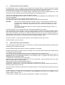
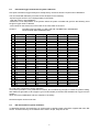
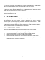
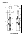
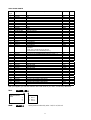
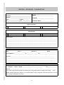
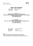
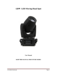
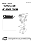
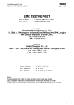
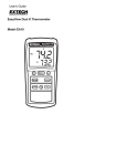
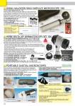
IMMERSION PROBE
USER MANUAL Nr. 135
EDITION 05/99
rev. 0
TABLE OF CONTENTS
Par.
1.0
Pag.
AN OUTLINE ON WATER DISINFECTION ....................................................
WARRANTY CONDITIONS ................................................................................................ 3
1.0
AN OUTLINE OF THE APPARATUS ............................................................. 4
1.1
Applications..................................................................................................... 4
1.2
Measurement types ........................................................................................ 4
2.0
DESCRIPTION ............................................................................................... 4
2.1
Full measurement system............................................................................... 4
2.2
Realization ...................................................................................................... 5
3.0
TECHNICAL CHARACTERISTICS ................................................................ 5
4.0
DIMENSIONS ................................................................................................ 5
5.0
SET UP ........................................................................................................... 6
6.0
ELECTRICAL CONNECTIONS ...................................................................... 6
7.0
STARTING...................................................................................................... 6
8.0
CALIBRATION ................................................................................................ 6
8.1
pH measurement system calibration .............................................................. 7
8.2
ORP measurement system calibration .......................................................... 7
8.3
Dissolved oxygen measurement system calibration ...................................... 8
8.4
ISE measurement system calibration ............................................................. 8
8.5
Conductivity measurement system calibration ............................................... 9
9.0
USE AND MAINTENANCE............................................................................. 9
10.0
ELECTRODES REPLACEMENT ................................................................... 9
11.0
SPARE PARTS............................................................................................. 10
11.1
Information for full SI/32 probe order ............................................................ 12
12.0
RETURN FOR REPAIR................................................................................ 12
12.1
Procedures under the care of customer ....................................................... 12
12.2
Repair procedure .......................................................................................... 12
REPAIR – REVISION – CALIBRATION SHEET ......................................... 15
2
As the first thing, thank you for your choice. Our products are manufactured according to
ISO 9001 procedures to assure maximum reliablity in any application, even in worst
conditions.
WARRANTY CONDITIONS
All our products, after manufacturing process, are subject to restrictive tests and are
warranted for 12 months from purchase date. Should any component fail during warranty
period, our Company will repair or replace at no charge, after having verified cause of
failure.
Warranty doe not include complete instrument replacement and our Company will reject
any request of indemnity for damages.
Repair on warranty is intended at our Service Department (ex-works): transport expenses
are on customer charge.
The customer is kindly requested to send the REPAIR – REVISION – CALIBRATION SHEET
fully filled in together with the instrument and to retain the original invoice or packing list as
a purchase evidence.
Warranty does not include: accidental ruptures during transport, failures due to uncorrect
use, to negligence, to wrong power supply connection, all the consumable and weary
parts and all accessories.
Warranty does not cover products that have been tampered with or repaired by non
authorized personne. Warranty does not cover requests for service.
Any disputes arising shall be settled in the Court of Milan under Italian law and
commercial customs.
1.0
AN OUTLINE OF THE APPARATUS
1.1
Applications
The SI/32 immersion electrodes holder probe, is built to house one of the following measurement electrodes:
pH, redox, ISE, conductivity, dissolved oxygen and temperature and to allow direct insertion in basin, tanks or
canals.
The extremely strong and compact built guarantees electrodes protection even in serious applications.
The probe has a sliding flange that simplifies mounting on wall, or on tub rim. The 300 mm version of the
SI/32 can be set up on a floating.
1.2
Measurement types
The SI/32 probe can host one electrode for pH, redox, ISE, conductivity, dissolved oxygen and temperature
measurements.
Electrodes that can be installed are:
3
MEASURE
DESCRIPTION
Mod.
pH
Combined electrode
101/V o 101/GEL
Redox
Combined electrode
201/V (Pt o Au) o 201/GEL (Pt o Au)
Conductivity
Conductivity sensor
401/L –K1
D.O.
Dissolved oxygen sensor
332/P
Temp.
Temperature sensor Pt100
PtL
On demand we can install, beyond pH, DO or conductivity electrode, a temperature sensor, fixed in the ring
nut electrodes holder.
2.0
DESCRIPTION
2.1
Full measurement system
The full measurement system is composed by the measurement electrode inserted in the sensor holder
probe, by the temperature sensor if required (inserted in the electrode holder ring nut), by the possible branch
box and by the electronic unit related to the parameter to measure.
Fig.1
2.2
FULL MEASUREMENT SYSTEM
Realization
The SI/32 probe is made of a PVC cylindrical body (PP, PVDF or INOX on demand), ∅ 32 mm and a
standard length of 600 mm (800 mm, 1000 mm, 1500 mm on demand); the 300 mm version for set up on a
floating is available on demand.
In the lower part of the body is screwed a waterproof sensor holder rest, in which can be inserted one of the
electrodes described in 1.2. O-rings guarantee the electrode seal.
The electrodes holder rest is threaded in the lower part and here the electrodes protection ring nut is
screwed.
The DN25 sliding flange can be positioned along all the probe body. To stop tighten the two socket head
screws.
On the superior part of the probe is mounted a closure cap, while the connection wire to the transmitter exit
by means of a waterproof fairlead on the superior part of the probe body.
3.0
TECHNICAL CHARACTERISTICS
Electrodes number:
1 (on demand temperature sensor inserted in electrode holder ring
nut )
4
Body material:
PVC, (PP, PVDF or INOX on demand)
Dimensions:
∅ 32, under flange standard length standard 600 mm (800mm, 1000
mm, 1500 mm, o demand); also available the 300 mm version for
floating set up
Wires outlet
Max working temperature:
(considering the electrodes
max temperature)
fairlead on probe’s superior side
PVC 60 °C
PP
70 °C
PVDF 90 °C
INOX 120 °C
Max stocking temperature:
0÷60 °C
Max pressure:
depending on the electrode type inserted
Dip depth:
depending on probe length; min immersion depth 100 mm
Fixing sliding flange:
DN25
Weight:
about 0,4 kg for the 600 mm version
Max distance from the electronic unit:
50 m (stopped wires)
4.0
DIMENSIONS
Fig.2
SI/32 IMMERSION PROBE OVERALL DIMENSIONS
5
5.0
SET UP
CAUTION:
The
measurement
and
reference electrodes mounted
in the probe are provided with
protection cap. Remember to
remove before use.
Fig.3 shows an example of
typical set up of the SI/32
immersion
probe
and
an
example of floating probe set up.
Place the probe in the process
vertically by means of the rest
flange DN”% (see fig.3) and
properly ad just immersion depth
using the two inox screws
sideways to the flange
(min
immersion depth 100 mm); make
always sure that process liquid is
moved and stirred and that the
probe
is
set
up
in
a
representative position.
It is now necessary to realize
electrical connections.
Fig.3 SI/32 PROBE TYPICAL SET UP
6.0
ELECTRICAL CONNECTIONS
Sensor is supplied complete with its wire.
Realize connection in the electronic unit following instructions in the specific user manual.
CAUTION!
7.0
Connection wires to the electronic unit must be steady set up and don’t have to pass
together with other cables. This eliminates troubles and interferences and allows to set up
the probe to a distance up to 50 m from the electronic unit.
STARTING
Once the probe is set up and connections to the electronic unit are realized, let operate the measurement
chain for half on hour to let the reading stabilize, then proceed with calibration.
8.0
CALIBRATION
After conditioning period (1/2 hour) calibration can start.
Following procedure mainly refer to sensors, the correct procedure to follow in calibrating electronics
depends on the electronic unit type used and can be found in the specific user manual.
6
8.1
pH measurement system calibration
pH measurement chain, is composed by a measurement electrode and by a reference electrode; voltage
produced by such a chain depends on different factors: the measurement electrode potential, the reference
electrode potential, the glass membrane potential, the potential due to the solution pH value.
So, even if the pH equality in the sample solution, potential produced will be slightly different for each
measurement chain; calibration realize the standardization of those little differences.
The pH chain calibration is made by means of buffered solutions.
Procedure to apply depends on the type of electronic unit connected (calibration with potentiometer or with
keyboard and display).
For further details refer to user manuals of different electronic unit.
We suggest to use the specific calibration glass (request to your provider, Mod.32-TAR).
CAUTION
Never dry the electrode rubbing it with rags, paper or other materials: electrodes have
an high ohmic resistance and rubbing the glass membrane produces a strong
polarization of the electrode reducing in this way up to 90% its answering speed to pH
variations.
If so, before any calibration wait for 10-15 min by leaving electrode plunged in water or in
the buffered solution.
Unscrew and remove the electrodes protection. Clean electrodes before proceeding.
In the clean beaker, pour a quantity of a pH 7.0 buffered solution enough to wet the electrodes; hold the
probe vertically and tighten the beaker. Allow that reading stabilizes, then do zero calibration in the electronic.
Then remove the beaker, throw the pH 7.0 buffered solution and rinse; pour the pH 4.0 buffered solution (or
other solutions) till the right level, rinse the electrode and screw the beaker. Allow the reading stabilizes then
calibrate slope on the electronic (according to the pH of the buffered solution used).
Remove the beaker , restore electrodes protection, then reinstall the probe in the process.
Now the analyzer can be set at work.
8.2
ORP measurement system calibration
The redox potential measurement chain is composed by a metallic (usually Gold and Platinum) measurement
electrode and by a reference electrode.
Redox potential measurement doesn’t require any calibration for operating.
Potential provided by the electrodes chain is the addition of the constant reference electrode potential and by
the sample liquid redox potential.
The resultant of those potentials could not be in the measurement range of the instrument.
For this reason ORP measurement electronics are equipped with an asymmetry command that allows to
algebraically add, to the potential provided by the electrodes chain, a potential that brings back the
measurement in the transmitter scale.
To realize this it is necessary to follow those steps :
Wash the probe’s edge with water and plunge it into the sample fluid. This must already have a pH value
suitable to the reaction we want to realize).
Wait for some minutes until measurement stabilizes.
(If transmitter’s indicator moves beyond full scale verify if connections are correct).
Operate on the potentiometer or on the zero calibration point until the zero value is showed on the electronic.
Now the analyzer can be set at work.
From this moment readings will indicate redox potential variations in the sample liquid compared to the zero
point preset.
Consider that redox potential measurement depends on all oxidants and reducents in the solution, and not
only to a specific ion. Therefore it is necessary to repeat calibration when and if the composition of the
sample solution changes in time.
On the contrary, if solution keep constant its characteristics, calibration is not necessary.
7
8.3
Dissolved oxygen measurement system calibration
Zero point in dissolved oxygen analyzer is usually factory set and so doesn’t require further calibrations.
The recommended calibration procedure for this analyzers is the following:
-expose oxygen sensor to air, keeping possibly in the shade.
-wait until sensor’s signal stabilizes
-measure the room temperature of the position where the probe is located and get from the following chart
the ppm oxygen value to calibrate
-correct slope on the electronics on the basis of the value read on the chart.
CHART 1
OXYGEN PPM VALUES TO USE FOR AIR CALIBRATION, DEPENDING
ON ALTITUDE AND TEMPERATURE
°C
775 mmHg
760 mmHg
L.M.
750 mmHg
120 m
725 mmHg
365 m
700 mmHg
610 m
675 mmHg
850 m
0
2
4
6
8
10
12
14
16
18
20
22
24
26
28
30
32
34
36
38
40
42
44
46
48
50
14.9
14.1
13.4
12.7
12.1
11.6
11.1
10.6
10.1
9.7
9.3
9.0
8.7
8.4
8.1
7.8
7.6
7.3
7.1
6.9
6.7
6.5
6.3
6.1
5.9
5.7
14.6
13.9
13.2
12.5
11.9
11.3
10.8
10.4
9.9
9.5
9.2
8.8
8.5
8.2
7.9
7.7
7.4
7.2
7.0
6.7
6.5
6.3
6.1
5.9
5.8
5.6
14.4
13.7
13.0
12.3
11.7
11.2
10.7
10.2
9.8
9.4
9.1
8.7
8.4
8.1
7.8
7.6
7.3
7.1
6.9
6.6
6.4
6.2
6.0
5.9
5.7
5.5
13.9
13.2
12.5
11.9
11.3
10.8
10.3
9.9
9.5
9.1
8.7
8.4
8.1
7.8
7.6
7.3
7.0
6.8
6.6
6.4
6.2
6.0
5.8
5.6
5.5
5.3
13.5
12.9
12.1
11.5
10.9
10.4
10.0
9.5
9.1
8.8
8.4
8.1
7.8
7.6
7.3
7.0
6.8
6.6
6.4
6.2
6.0
5.8
5.6
5.4
5.3
5.1
12.9
12.3
11.7
11.1
10.5
10.1
9.6
9.2
8.8
8.4
8.1
7.8
7.5
7.3
7.0
6.8
6.6
6.3
6.1
5.9
5.7
5.6
5.4
5.2
5.0
4.9
As a rule, zero point doesn’t require calibration.
It is however possible to verify calibration as follows: fill a container big enough to contain the probe’s trailing,
with distilled or light water, melt in approx 1g/l of sodium sulfite (a reducent that eliminates all oxygen from the
solution)
Allow the sensor stabilization and zero calibrate, if necessary.
Now the analyzer can be set at work.
8.4
ISE measurement system calibration
In calibrating selective ions analyzers, we recommend to carefully follow instructions supplied with each ISE
sensor. This because they are so different each other in shape, slope and in use.
8
8.5
Conductivity measurement system calibration
For conductivity measurement system calibration, it is necessary to acquire at least one standard solution
with known conductivity value ( the solution type is related to the full scale of the analyzer).
Then proceed as follows:
- Unscrew the electrodes protection from the probe, rinse and drip the electrode, fill to the correct level
calibration beaker and insert the electrode
- Wait for some minutes until reading stabilizes and verify if reading of the electronic matches with standard
solution value. If necessary correct slope working on electronic unit.
Restore electrodes protection, then reinstall the probe.
Now the analyzer can be set at work.
9.0
USE AND MAINTENANCE
We recommend to regularly clean sensor: Frequency depends on the process type and will be established on
a direct experience basis.
We also recommend, after cleaning the sensor, to regularly – depending on direct experience - verify the
measurement and if necessary recalibrate it (to verify the measurement proceed either with a portable
measurer opportunely calibrated, or plunging the probe into a solution with a known concentration of the
measurement parameter and verifying that reading matches with such value).
To diminish cleaning operation frequency, it is possible to acquire by your provider, the chemical cleaning kit,
Mod.SI/CH-AP and the board to control cleaning sequence (Mod.QAPCH).
10.0 ELECTRODES REPLACEMENT
Refer to fig. 4 “SI/32 Assembling scheme” for a better comprehension of the following description.
1.
2.
3.
4.
5.
6.
Unscrew the electrode holder (7) from the probe’s body (9) making sure not to twist cables.
Take out the electrode holder joint sliding cable through probe’s body.
Extract the electrode to substitute from electrodes holder joint pulling up.
We recommend to substitute the specific O-Ring (6), when the electrode is replaced
Replace the broken electrode and position it to obtain the correct projection
Reassemble the probe and close it again executing the above instructions in opposite direction
Note:
If the shielded cable of the measurement electrode has to be restored (for pH, redox and ISE),
ensure that the black semi conductive sheath located between the shielding and the internal wire
polyethylene protection is removed for at least 20 mm.
9
11.0 SPARE PARTS
Refer to Fig.4 “SI/32 assembling scheme” and to the following chart. Remember to mention, in the possible
order, model and serial number of your product, as well as the spare part code of the required component.
Fig.4
SI/32 ASSEMBLING SCHEME
10
SI/32 SPARE PARTS
Pos.in
Fig.4
1
1
1
1
2
3
3
3
3
4
4
4
4
4
4
4
5
5
5
5
6 + 11
7
7
7
7
7
7
7
7
8
8
8
8
9
9
9
9
10
10
10
10
Spare code
S32-001
S32-002
S32-003
S32-004
S32-005
S32-006
S32-007
S32-008
S32-009
101/N
101/N-DG-SM
201/N (Pt O Au)
201/N (Pt O Au)
401/L-K1
332/P
Pt/L
S32-010
S32-011
S32-012
S32-013
S32-014
S32-015
S32-016
S32-017
S32-018
S32-019
S32-020
S32-021
S32-022
S32-023
S32-024
S32-025
S32-026
S32-027
S32-028
S32-029
S32-030
S32-031
S32-032
S32-033
S32-034
S32-035
Description
CAP
CAP
CAP
CAP
RUBBER FAIRLEAD 34.21.230
BODY
BODY
BODY
BODY
pH ELECTRODE
pH ELECTRODE
REDOX ELECTRODE
REDOX ELECTRODE
CONDUCTIVITY ELECTRODE
DISSOLVED OXYGEN ELECTRODE
TEMPERATURE SENSOR
O-R PUSHER
O-R PUSHER
O-R PUSHER
O-R PUSHER
OR SPARE KIT
It contains:
n°1OR 115 11.91x2.62x17.15 (Pos.6)
n°3 OR2100 25.12x1.78x28.68 (Pos.11)
NIPPLE WITH THERMORESISTANCE for SI/32…C
NIPPLE WITH THERMORESISTANCE for SI/32…C
NIPPLE WITH THERMORESISTANCE for SI/32…C
NIPPLE WITH THERMORESISTANCE for SI/32…C
NIPPLE WITHOUT THERMORESISTANCE for SI/32
NIPPLE WITHOUT THERMORESISTANCE for SI/32
NIPPLE WITHOUT THERMORESISTANCE for SI/32
NIPPLE WITHOUT THERMORESISTANCE for SI/32
PROTECTION
PROTECTION
PROTECTION
PROTECTION
PROBE EXTENSION
PROBE EXTENSION
PROBE EXTENSION
PROBE EXTENSION
NIPPLE FOR PROBE EXTENSION
NIPPLE FOR PROBE EXTENSION
NIPPLE FOR PROBE EXTENSION
NIPPLE FOR PROBE EXTENSION
DN25 PROBE SUPPORT FLANGE
Material
PVC
PP
PVDF
INOX
PVC
PP
PVDF
INOX
PVC
PP
PVDF
INOX
PVC
PP
PVDF
INOX
PVC
PP
PVDF
INOX
PVC
PP
PVDF
INOX
PVC
PP
PVDF
INOX
PVC
PP
PVDF
INOX
Q.ty
1
1
1
1
1
1
1
1
1
1
1
1
1
1
1
1
1
1
1
1
1+
3
1
1
1
1
1
1
1
1
1
1
1
1
1
1
1
1
1
1
1
1
1
With your supplier you can find solutions with fixed value for pH, redox, conductivity calibration.
Mod.
! - !
T/101–
Buffered solution
value
Bottles
1
4
7
Mod.
T/401– !
A
B
C
250 cc
500 cc
1000 cc
Specify desired conductivity value: 1 mS, 12 mS, 100 mS.
11
11.1
Information for full SI/32 probe order
SI/32 - ! - !
Material
PVC 1
PP
2
PVDF 3
INOX 4
Length
1 = 600 mm
2 = 800 mm
3 = 1000 mm
4 = from 1000 to 1500 mm on
demand
12.0 RETURN FOR REPAIR
Should any equipment misfunctioning appear, pls contact our Technical Department.
Should the equipment be broken or faulty pls proceed to return for rapair as described hereafter.
12.1
Procedures under the care of customer
Fill in each part the enclosed REPAIR – REVISION – CALIBRATION sheet
Attach the form to the equipment and ship them to:
The material will be sent ex warehouse. To avoid unpleasant trouble, we inform the Customers that carriage
forward shipping will not be accepted.
12.2
Repair procedure
When the material with the form REPAIR – REVISION – CALIBRATION will be received, we will send, as
soon as possible, an estimated cost, before proceeding to any intervention on the equipment.
To each equipment received for repair or revision we assign a number that will be used as the reference for
all the techniacl and commercial information.
No intervention will be carried out on the equipment without previous customer written approval.
Should the the repair cost estimate require some work, a minimum of 150.000 Itl. will be invoiced, even if the
customer does not confirm the approval to repair.
Repairs under warranty won’t be invoiced, except for freight cost, that will always be charged to customer.
Should any information be required, pls, contact our technical and commercial department.
12
REPAIR – REVISION - CALIBRATION
Company__________________________________
Address___________________________________
Mod.N.________________________
Serial N.________________________
Town___________________Nation___________
Tel._____________________Fax_______________
Purchase date____________________
Type of operation
Repair
Revision
Calibration
Detected fault
As the good has been received
During calibration procedure
At start up
Intermittent
After apprx.
Steady
-
Detected fault:___________________________________________________________________
_____________________________________________________________________________________
_____________________________________________________________________________________
_____________________________________________________________________________________
_____________________________________________________________________________________
_____________________________________________________________________________________
Riservato al costruttore
Date________________ Rip. n°_________________ Invoice n°_________________ dated___________
Cost estimate n°_________________ of___________ ________ Lit.___________________________
Remarks:__________________________________________________________________________
_____________________________________________________________________________________
_____________________________________________________________________________________
_____________________________________________________________________________________
Equipment return
-
Customer
carrier
Name___________________________________
Tel.________________
Address_______________________________________________________________________________
- Our carrier with 25.000 Itl charge on invoice (up to 0.3 kg) and 30.000 Itl. charge (up to 20 kg)
+ VAT
NOTE: if written approval for reapair is not received within 40 days, the goods will be returned with our carrier
with a charge of 200.000 Itl on invoice.
13
14