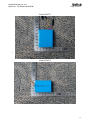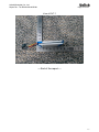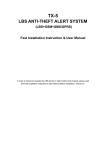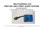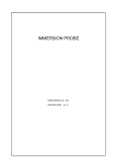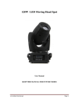
1
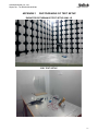
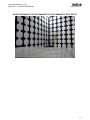
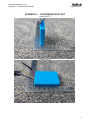
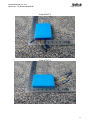
Unilab(Shanghai) Co.,Ltd.
Report No. : UL45520150619CE001
Page 1 of 23
EMC TEST REPORT
Product Name
Model Name
:
:
Lithium-ion Polymer Battery
HCP484555NFC-2S1P
Prepared for:
Shenzhen Honcell Energy Co., Ltd.
612, Bldg. A, Weidonglong Industrial Zone, Meilong Ave.194#, Longhua
New District, Shenzhen, 518109, China.
TEL: 0755-23731316
FAX: 0755-23731319
Prepared by:
Unilab (Shanghai) Co., Ltd.
Floor 1, No. 1350, Lianxi Rd. Pudong New District, Shanghai, China
TEL: +86-21-5027 5125
FAX: +86-21-5027 5126
Report Number
Date of Report
Date of Test
:
:
:
UL45520150619001
06-26-2015
06-19-2015~06-26-2015
Notes:
The test results only relate to these samples which have been tested.
Partly using this report will not be admitted unless been allowed by Unilab.
Unilab is only responsible for the complete report with the reported stamp of Unilab.
1
Unilab(Shanghai) Co.,Ltd.
Report No. : UL45520150619CE001
Page 2 of 23
Applicant:
Shenzhen Honcell Energy Co., Ltd.
612, Bldg. A, Weidonglong Industrial Zone, Meilong Ave.194#, Longhua
New District, Shenzhen, 518109, China.
Manufacturer:
Shenzhen Honcell Energy Co., Ltd.
612, Bldg. A, Weidonglong Industrial Zone, Meilong Ave.194#, Longhua
New District, Shenzhen, 518109, China.
Product Name:
Lithium-ion Polymer Battery
Brand Name:
HC
Model Name:
HCP484555NFC-2S1P
Technical Data: DC:7.4V 1400mAh
Date of Receipt: 06-19-2015
Date of Test:
06-19-2015~06-26-2015
Test Standard:
EN 55022: 2010+AC:2011
EN 55024: 2010
Test Result:
PASS
Prepared by :
(Technical Engineer: Paul Yang)
Reviewed by :
(Senior Engineer: Forest Cao)
Approved by :
(Supervisor Engineer: Eva Wang)
2
Unilab(Shanghai) Co.,Ltd.
Report No. : UL45520150619CE001
Page 3 of 23
TABLE OF CONTENTS
1.
GENERAL INFORMATION .................................................................................. 4
1.1
EUT DESCRIPTION ................................................................................... 4
1.2
TEST MODE DESCRIPTION ..................................................................... 4
2.
TECHNIACL SUMMARY ...................................................................................... 5
2.1
SUMMARY OF STANDARDS AND TEST RESULTS ............................... 5
2.2
TEST UNCERTAINTY................................................................................ 5
2.3
TEST EQUIPMENT LIST ........................................................................... 6
2.4
TEST FACILITY ......................................................................................... 6
2.5
Immunity Performance Criteria ............................................................... 7
2.6
TEST SETUP CONFIGURATION .............................................................. 8
3.
RADIATED DISTURBANCE (RE) ........................................................................ 9
3.1
TEST SETUP ............................................................................................. 9
3.2
LIMITS........................................................................................................ 9
3.3
TEST PROCEDURE ................................................................................ 10
3.4
TEST RESULT ......................................................................................... 11
4.
ELECTROSTATIC DISCHARGE (ESD) ............................................................. 13
4.1
TEST SPECIFICATION............................................................................ 13
4.2
TEST SETUP ........................................................................................... 13
4.3
TEST PROCEDURE ................................................................................ 13
4.4
RESULTS & PERFORMANCE ................................................................ 14
5.
RF ELECTROMAGNETIC FIELD IMMUNITY .................................................... 16
5.1
TEST SPECIFICATION............................................................................ 16
5.2
TEST SETUP ........................................................................................... 16
5.3
TEST PROCEDURE ................................................................................ 16
5.4
RESULTS & PERFORMANCE ................................................................ 17
APPENDIX 1
PHOTOGRAPHS OF TEST SETUP.............................................. 18
APPENDIX 2
PHOTOGRAPHS OF EUT ............................................................ 20
3
Unilab(Shanghai) Co.,Ltd.
Report No. : UL45520150619CE001
Page 4 of 23
1. GENERAL INFORMATION
1.1 EUT DESCRIPTION
Product Name:
Model Name:
Technical Data:
Lithium-ion Polymer Battery
HCP484555NFC-2S1P
7.4V, 1400mAh, Double batteries
1.2 TEST MODE DESCRIPTION
Unilab has verified the construction and function in typical operation. All the test modes
were carried out with the EUT in normal operation, which was shown in this test report
is the worst test mode.
Final Test Mode
Final Test Mode
EMI
Discharge Operation
EMS
Discharge Operation
4
Unilab(Shanghai) Co.,Ltd.
Report No. : UL45520150619CE001
Page 5 of 23
2. TECHNIACL SUMMARY
2.1 SUMMARY OF STANDARDS AND TEST RESULTS
The EUT have been tested according to the applicable standards as referenced below:
EMISSION
Test Item
Standard
Result
N/A 1
Conducted disturbance
EN 55022:2010+AC:2011
Radiated disturbance
EN 55022:2010
Harmonic current emission
EN 61000-3-2:2006+A1:2009+A2:2009
N/A
Voltage fluctuations & flicker
EN 61000-3-3:2008
N/A
P
IMMUNITY (EN 55024: 2010)
Test Item
Standard
Result
Electrostatic discharge (ESD)
IEC 61000-4-2
P
Radio-frequency electromagnetic
field Immunity
IEC 61000-4-3
P
Electrical fast transients (EFT)
IEC 61000-4-4
N/A
Surges
IEC 61000-4-5
N/A
Radio-frequency continuous
conducted Immunity
IEC 61000-4-6
N/A
Power-frequency magnetic fields
Immunity
IEC 61000-4-8
N/A
Voltage dips and interruptions
IEC 61000-4-11
N/A
Note *: 1: P means pass, F means failure, N/A means not applicable.
2.2 TEST UNCERTAINTY
Where relevant, the following test uncertainty levels have been estimated for tests
performed on the EUT as specified in CISPR 16-4-2. This uncertainty represents an
expanded uncertainty expressed at approximately the 95% confidence level using a
coverage factor of k=2.
Test item
Value (dB)
Radiated disturbance
4.2
5
Unilab(Shanghai) Co.,Ltd.
Report No. : UL45520150619CE001
Page 6 of 23
2.3 TEST EQUIPMENT LIST
3M Semi-anechoic Chamber - Radiated disturbance Test
Equipment
3M Chamber &
Accessory Equipment
Receiver
Manufacturer
Model
Serial No.
Due Date
ETS-LINDGREN
FACT-3
CT-0000336
11/25/2015
Agilent
N9038A
MY51210142
11/11/2015
Biconilog Antenna
SCHWARZBECK
VULB 9160
3316
09/19/2016
Shielding Room No. 2 - ESD Test (IEC 61000-4-2)
Equipment
Manufacturer
Model
Serial No.
Due Date
ESD Simulator
EM TEST AG
Dito Version 2.31
DM-1132
09/04/2015
3M Full-anechoic Chamber - RF electromagnetic field Immunity Test (IEC 61000-4-3)
Equipment
Manufacturer
Model
Serial No.
Due Date
Power Meter
R&S
NRVD
101457
11/04/2015
Signal generators
R&S
SMR20
101440
11/04/2015
Power Amplifier
B&K
BLWA
056186-01
07/20/2015
VHF/UHF EMS Antenna
SCHWARZBECK
HL046E
100008
10/15/2015
The measuring equipment utilized to perform the tests documented in this report has been
calibrated once a year or in accordance with the manufacturer's recommendations, and has
been calibrated by accredited calibration laboratories.
2.4 TEST FACILITY
The site and apparatus are constructed in conformance with the requirements of ANSI
C63.4, CISPR 16-1-1 and other equivalent standards. The laboratory is compliance with the
requirements of the ISO/IEC/EN 17025.
6
Unilab(Shanghai) Co.,Ltd.
Report No. : UL45520150619CE001
Page 7 of 23
2.5 Immunity Performance Criteria
The manufacturer has the obligation to express the performance criteria in terms which
relate to the performance of his specific product when used as intended.
The following performance criteria are applicable, and shall only be evaluated when the
functions referred to are implemented.
Examples of functions defined by the manufacturer to be evaluated during testing include,
but are not limited to, the following:
– essential operational modes and states;
– tests of all peripheral access (hard disks, floppy disks, printers, keyboard, mouse, etc.);
– quality of software execution;
– quality of data display and transmission;
– quality of speech transmission.
General Performance Criteria
Product Standard
EN 55024:2010
CRITERION A
During and after the test the EUT shall continue to operate as intended
without operator intervention. No degradation of performance or loss of
function is allowed below a minimum performance level specified by the
manufacturer when the EUT is used as intended. The performance level may
be replaced by a permissible loss of performance. If the minimum
performance level or the permissible performance loss is not specified by the
manufacturer, then either of these may be derived from the product
description and documentation, and by what the user may reasonably expect
from the EUT if used as intended.
After the test, the EUT shall continue to operate as intended without operator
intervention. No degradation of performance or loss of function is allowed,
after the application of the phenomena below a performance level specified
by the manufacturer, when the EUT is used as intended. The performance
level may be replaced by a permissible loss of performance.
CRITERION B
During the test, degradation of performance is allowed. However, no change
of operating state or stored data is allowed to persist after the test.
If the minimum performance level (or the permissible performance loss) is not
specified by the manufacturer, then either of these may be derived from the
product description and documentation, and by what the user may
reasonably expect from the EUT if used as intended.
During and after testing, a temporary loss of function is allowed, provided the
function is self-recoverable, or can be restored by the operation of the controls or
CRITERION C
cycling of the power to the EUT by the user in accordance with the manufacturer’s
instructions. Functions, and/or information stored in non-volatile memory, or
protected by a battery backup, shall not be lost.
Functions, and/or information stored in non-volatile memory, or protected by a
battery backup, shall not be lost.
7
Unilab(Shanghai) Co.,Ltd.
Report No. : UL45520150619CE001
Page 8 of 23
2.6 TEST SETUP CONFIGURATION
See test photographs attached in Appendix 1 for the actual connections between EUT and
support equipment.
Notes:
1. All the equipment/cables were placed in the worst-case configuration to maximize the emission during
the test.
2. Grounding was established in accordance with the manufacturer’s requirements and conditions for the
intended use.
8
Unilab(Shanghai) Co.,Ltd.
Report No. : UL45520150619CE001
Page 9 of 23
3. RADIATED DISTURBANCE (RE)
3.1 TEST SETUP
30MHz ~ 1GHz:
Above 1GHz:
3.2 LIMITS
EN Limits for radiated disturbance of Class B ITE
Frequency (MHz)
Quasi-peak limits at 3m
dB(μV/m)
30-230
40
230-1000
47
Frequency (GHz)
limit above 1G at 3m
dB(μV/m)
Average
peak
1-3
50
70
3-6
54
74
NOTE: The lower limit shall apply at the transition frequencies.
9
Unilab(Shanghai) Co.,Ltd.
Report No. : UL45520150619CE001
Page 10 of 23
3.3 TEST PROCEDURE
30MHz ~ 1GHz:
a. The EUT and support equipment were placed on the non-conductive turntable 0.8m
above the horizontal metal ground plane at a chamber. The EUT was set 3 meters away
from the receiving antenna, which was mounted on an antenna tower. Broadband antenna
(Calibrated Bilog Antenna) was used as receiving antenna.
b. The frequency range from 30MHz to 1GHz was checked. The RBW of the receiver was
set at 120kHz. Set the receiver in Peak detector, Max Hold mode. Record the maximum field
strength of all the pre-scan process in the full band when the antenna is varied between 1~4
m in both horizontal and vertical, and the turntable is rotated from 0 to 360 degrees.
c. For each frequency whose maximum record was higher or close to limit, measure its QP
value: vary the antenna’s height and rotate the turntable from 0 to 360 degrees to find the
height and degree where EUT radiated the maximum emission, then set the test frequency
receiver to QP Detector and record the maximum value.
Above 1GHz:
a. The EUT and support equipment were placed on the non-conductive turntable 0.8m
above the ground at a chamber. The EUT was set 3 meters away from the receiving
antenna, which was mounted on an antenna tower. Horn antenna was used as receiving
antenna.
b. The frequency range above 1GHz was checked. The RBW of the receiver was set at
1MHz. Set the receiver in Peak detector, Max Hold mode. Record the maximum field
strength of all the pre-scan process in the full band when the antenna is 1m and varied in
both horizontal and vertical, and the turntable is rotated from 0 to 360 degrees.
c. For each frequency whose maximum record was higher or close to limit, measure its
Average value: rotate the turntable from 0 to 360 degrees to find the degree where EUT
radiated the maximum emission, then set the test frequency receiver to EMI Average
Detector and record the maximum value.
10
Unilab(Shanghai) Co.,Ltd.
Report No. : UL45520150619CE001
Page 11 of 23
3.4 TEST RESULT
30MHz ~ 1GHz:EN
Test mode:
Full load and connect network cable
11
Unilab(Shanghai) Co.,Ltd.
Report No. : UL45520150619CE001
Page 12 of 23
12
Unilab(Shanghai) Co.,Ltd.
Report No. : UL45520150619CE001
Page 13 of 23
4. ELECTROSTATIC DISCHARGE (ESD)
4.1 TEST SPECIFICATION
Basic Standard
Test Port
Discharge Impedance
Discharge Mode
Discharge Period
:
:
:
:
:
EN 55024 & IEC 61000-4-2
Enclosure port
330 ohm / 150 pF
Single Discharge
one second between each discharge
4.2 TEST SETUP
4.3 TEST PROCEDURE
The test applied a non-conductive surface and a horizontal coupling plane on a wooden
table, 0.8 m high, standing on the reference ground plane, which is a 3 m x 4 m metallic
sheet with 1.5 mm thickness. This reference ground plane projected beyond the EUT by at
least 0.5 m on all sides and the minimum distance between the EUT and all other conductive
structure, except the ground plane beneath the EUT, was more than 1.0 m.
ESD shall be applied only to those points and surfaces of the EUT which are expected to be
touched during usual operation, including user access, as specified in the user manual.
The discharges shall be applied in the following:
A. Contact discharge (Tests shall be performed at a maximum repetition rate of one
discharge per second.):
a. Direct discharge:
The tip of the discharge electrode should touch the EUT, before the discharge switch was
operated. The EUT shall be exposed to at least 200 discharges, 100 each at negative and
positive polarity, at a minimum of four test points (a minimum of 50 discharges at each
point). One of the test points shall be subjected to at least 50 indirect discharges (contact) to
the center of the front edge of the horizontal coupling plane. If no direct contact test points
are available, then at least 200 indirect discharges shall be applied in the indirect mode (use
of the Vertical Coupling Plane)
b. Indirect discharge:
b1. Horizontal Coupling Plane (HCP): More than 50 single discharges were applied at the
front edge of each HCP opposite the center point of the EUT and 0.1m from vertically the
front of the EUT. Discharge to the HCP was made horizontal to the edge of the HCP.
13
Unilab(Shanghai) Co.,Ltd.
Report No. : UL45520150619CE001
Page 14 of 23
b2. Vertical Coupling Plane (VCP): More than 50 single discharges were applied to the
center of one vertical edge of the coupling plane. The coupling plane, of dimensions 0.5 m x
0.5 m, was placed parallel to, and positioned at a distance of 0. m from the EUT. Discharges
were applied to the coupling plane, with this plane in sufficient different positions that all
sides of the EUT were completely illuminated.
B. Air discharge at slots and apertures, and insulating surfaces:
On those parts of the EUT where it is not possible to perform contact discharge testing, the
equipment should be investigated to identify user accessible points where breakdown may
occur. Such points are tested using the air discharge method. The round discharge tip of the
discharge electrode was approached as fast as possible to touch the EUT. After each
discharge, the ESD simulator (discharge electrode) was removed from the EUT. The
simulator was then re-trigged for a new single discharge and applies more than 10 times on
each reselected point. This procedure was repeated until the air discharge completed.
4.4 RESULTS & PERFORMANCE
Discharge point:
14
Unilab(Shanghai) Co.,Ltd.
Report No. : UL45520150619CE001
Page 15 of 23
EUT
: Lithium-ion Polymer Battery
Humidity : 51%
Mode
: Discharge Operation
M/N
Temperature
: HCP484555NFC-2S1P
: 22℃
Air discharge (Direct discharge)
Test location
Test level
(±kV)
Minimum number of discharge
per polarity (each location)
1~61
4,6,8
10
Result
(Pursuant to
EN55024,Criterion A)
PASS
Contact discharge (HCP)
Test
location
Test level
(±kV)
Minimum number of discharge per
polarity (each location)
Front
2,4
25
Result
(Pursuant to
EN55024,Criterion A)
PASS
Rear
2,4
25
PASS
Left
2,4
25
PASS
Right
2,4
25
PASS
Contact discharge (VCP)
Test
location
Test level
(±kV)
Minimum number of discharge per
polarity (each location)
Front
2,4
25
Result
(Pursuant to
EN55024,Criterion A)
PASS
Rear
2,4
25
PASS
Left
2,4
25
PASS
Right
2,4
25
PASS
Note 1: These points are evaluated before the test. They could be discharged in the process of actual
test.
15
Unilab(Shanghai) Co.,Ltd.
Report No. : UL45520150619CE001
Page 16 of 23
5. RF ELECTROMAGNETIC FIELD IMMUNITY
5.1 TEST SPECIFICATION
Basic Standard
Test Port
Step Size
Modulation
Dwell Time
Polarization
:
:
:
:
:
:
EN 61000-4-3
Enclosure port
1%
1kHz, 80% AM
1 second
Horizontal & Vertical
5.2 TEST SETUP
5.3 TEST PROCEDURE
a. The EUT and support equipment were placed on the non-conductive table 0.8m above
the ground plane at a fully-anechoic chamber. The transmit antenna was located at a
distance of 3 meters from the EUT and support equipment.
b. The frequency range is swept from 80MHz to 1000MHz, with the signal 80% amplitude
modulated with a 1 kHz sine wave. The rate of sweep did not exceed 1.5x 10 -3 decade/s.
Where the frequency range is swept incrementally, the step size was 1%. The dwell time at
each frequency shall be not less than the time necessary for the EUT to be able to respond.
c. The test was performed with the EUT exposed to both vertically and horizontally polarized
fields on each side. A CCD camera was put inside the chamber and through its display to
monitor the operational situation of the EUT to judge the EUT performance criterion during
test.
16
Unilab(Shanghai) Co.,Ltd.
Report No. : UL45520150619CE001
Page 17 of 23
5.4 RESULTS & PERFORMANCE
EUT
: Lithium-ion Polymer Battery
Humidity : 53%
Mode
: Discharge Operation
M/N
Temperature
: HCP484555NFC-2S1P
: 23℃
Frequency
(MHz)
EUT Position
Antenna
Polarization
Field Strength
(V/m)
Result
80 - 1000
Front
Horizontal
3
PASS
80 - 1000
Front
Vertical
3
PASS
80 - 1000
Rear
Horizontal
3
PASS
80 - 1000
Rear
Vertical
3
PASS
80 - 1000
Left
Horizontal
3
PASS
80 - 1000
Left
Vertical
3
PASS
80 - 1000
Right
Horizontal
3
PASS
80 - 1000
Right
Vertical
3
PASS
80 - 1000
Floor
Horizontal
3
PASS
80 - 1000
Floor
Vertical
3
PASS
80 - 1000
Top
Horizontal
3
PASS
80 - 1000
Top
Vertical
3
PASS
17
Unilab(Shanghai) Co.,Ltd.
Report No. : UL45520150619CE001
APPENDIX 1
Page 18 of 23
PHOTOGRAPHS OF TEST SETUP
RADIATED DISTURBANCE TEST SETUP-30M~1G
ESD TEST SETUP
18
Unilab(Shanghai) Co.,Ltd.
Report No. : UL45520150619CE001
Page 19 of 23
RADIO-FREQUENCY ELECTROMAGNETIC FIELD IMMUNITY TEST SETUP
19
Unilab(Shanghai) Co.,Ltd.
Report No. : UL45520150619CE001
APPENDIX 2
Page 20 of 23
PHOTOGRAPHS OF EUT
View of EUT-1
View of EUT-2
1
2
2
1
20
Unilab(Shanghai) Co.,Ltd.
Report No. : UL45520150619CE001
Page 21 of 23
View of EUT-3
View of EUT-4
21
Unilab(Shanghai) Co.,Ltd.
Report No. : UL45520150619CE001
Page 22 of 23
View of EUT-5
1
2
2
1
View of EUT-6
22
Unilab(Shanghai) Co.,Ltd.
Report No. : UL45520150619CE001
Page 23 of 23
View of EUT-7
----End of the report----
23