1
e 824 WindowTouch4 Operation Manual 17‐00001‐C Page | 1 © 2012 HAEGER, INC. All rights reserved. No part of this work may be reproduced, copied, adapted, or transmitted in any form or by any means without written permission from HAEGER, INC. HAEGER, INC makes no representation or warranties with respect to the contents hereof and specifically disclaims any implied warranties of merchantability or fitness for any particular purpose. Further, HAEGER, INC reserves the right to revise this publication and to make changes from time to time in the content hereof without obligation to notify any person of such revision or changes. Table of Contents SECTION 1 ‐ INTRODUCTION .......................................................................................................... 7 Congratulations! ............................................................................................................................ 7 Haeger Locations Worldwide ........................................................................................................ 7 Statement of Foreseen Use ........................................................................................................... 9 Safety Information (also see section 3) ......................................................................................... 9 Customer Service (also see section 6) ........................................................................................... 9 Responsibilities of the Operator .................................................................................................... 9 Responsibilities of the Service Technician ................................................................................... 10 Quality of Parts & Fasteners ........................................................................................................ 10 Basic data sheet ........................................................................................................................... 11 Illistration of safety notes ............................................................................................................ 12 Details of location in the documentation .................................................................................... 13 Safety precautions and warnings ................................................................................................ 14 SECTION 2 ‐ INSTALLATION .......................................................................................................... 15 Handling ....................................................................................................................................... 15 Recommended Safe Work Zone .................................................................................................. 16 Skid removal ............................................................................................................................... 17 Machine setup ............................................................................................................................ 18 Main power set‐up ...................................................................................................................... 20 Machine operator basic controls ................................................................................................. 21 Testing of the electrical set‐up .................................................................................................... 23 The Upper Tool Holder ................................................................................................................ 25 The Turret Insertion System (T.I.S.) ............................................................................................. 26 Tooling storage ............................................................................................................................ 27 Quick mount mutli‐shuttle .......................................................................................................... 28 Quick mount TIS‐3 ....................................................................................................................... 29 Quick Mount Auto Tooling .......................................................................................................... 30 Modular Auto Feed System (MAS 350) ....................................................................................... 31 Conductive mode set‐up procedure ...................................................................................... 32 Getting started – Before you turn on the machine ............................................................... 32 Setting the machine ............................................................................................................... 32 Checking the up travel & insertion ........................................................................................ 32 Non‐conductive mode set‐up procedure .............................................................................. 34 17‐00001‐C Page | 2 Getting started – Before you turn on the machine ............................................................... 34 Setting the machine ............................................................................................................... 34 Checking the up travel & insertion ........................................................................................ 34 SECTION 3 – HAEGER SAFETY SYSTEM .......................................................................................... 36 Safety system description ............................................................................................................ 37 Conductive Mode ........................................................................................................................ 37 Non‐conductive mode ................................................................................................................. 37 How the safety system works ...................................................................................................... 37 Lockout‐Tagout ............................................................................................................................ 39 Fire Safety Equipment ................................................................................................................. 42 Safety Awareness & Residual Risks ....................................................................................... 43 Introduction ........................................................................................................................... 43 1. Situations and Actions to Avoid ......................................................................................... 43 2. Residual Safety Risks .......................................................................................................... 43 Operator Safety Awareness & Residual Risks ........................................................................ 44 Maintenance Safety Awareness & Residual Risks ................................................................. 46 Safety System Tests .............................................................................................................. 47 Step 1: Safety switch test procedure ..................................................................................... 47 Step 2: conductive mode test ................................................................................................ 49 Step 3: Non‐conductive mode test ........................................................................................ 51 SECTION 4 – TOUCH SCREEN OPERATION (Step by Step Demo) .................................................... 53 Window Touch‐4e ‐ Introduction ................................................................................................ 53 Touch Screen Hierarchy Overview .............................................................................................. 54 Quick Run Step by Step Demo ............................................................................. 56 User Login .................................................................................................................................... 57 Password ...................................................................................................................................... 57 Input 1: Station ............................................................................................................................ 58 Input 2: Material .......................................................................................................................... 58 Input 3: Fastener ......................................................................................................................... 58 Input 4: Unit & Size ...................................................................................................................... 59 Input 5: Insertion Values ............................................................................................................. 59 Force (LBS) ............................................................................................................................. 59 Dwell (Sec).............................................................................................................................. 60 Up Travel (%) .......................................................................................................................... 60 Input 6: MAS Values .................................................................................................................... 60 Eject Time (Sec) ...................................................................................................................... 60 Vibration (%) .......................................................................................................................... 61 Vibration Time (Sec) ............................................................................................................... 61 Input 7: Quality Control ............................................................................................................... 61 Tooling Protection System (TPS) ............................................................................................ 61 Fastener Length ..................................................................................................................... 62 Fastener Detection ................................................................................................................. 62 Input: Status ................................................................................................................................ 62 Clamp ..................................................................................................................................... 62 Vacuum .................................................................................................................................. 63 17‐00001‐C Page | 3 Tooling.................................................................................................................................... 63 Modular Auto Feed System (MAS) ......................................................................................... 63 Eject Fastener ......................................................................................................................... 64 Setup Stroke ........................................................................................................................... 64 Programs Setup Step by Step Demo ...................................................................... 66 User Login .................................................................................................................................... 68 Password ...................................................................................................................................... 68 Programs ...................................................................................................................................... 69 Create New Program ................................................................................................................... 69 Program Name ............................................................................................................................. 69 New Customer ............................................................................................................................. 70 Program Notes ............................................................................................................................. 70 Fastener Differentiation .............................................................................................................. 70 Program Wizard (Automatic or Manual, Station 1 of 4) .............................................................. 71 1. Preset: ................................................................................................................................ 71 Library ............................................................................................................................. 71 Part Material ................................................................................................................... 71 2. Fastener: ............................................................................................................................ 71 Manufacturer .................................................................................................................. 71 Type ................................................................................................................................ 72 3. Size ..................................................................................................................................... 72 Unit of Measure .............................................................................................................. 72 Fastener Length .............................................................................................................. 72 Part Identification ........................................................................................................... 72 4. Select Tooling Type ............................................................................................................ 73 Program Wizard (Manual, Station 2 of 4) .................................................................................... 73 Program Wizard (Manual, Station 3 of 4) .................................................................................... 75 Program Wizard (Manual, Station 4 of 4) .................................................................................... 76 Add Insertion Group (Station 1) .................................................................................................. 78 Amount .................................................................................................................................. 78 Part Image .............................................................................................................................. 79 Location: USB HDD ................................................................................................................. 79 Select Insertion Points ........................................................................................................... 80 Add Insertion Group (Station 2) .................................................................................................. 81 Add Insertion Group (Station 3) .................................................................................................. 83 Add Insertion Group (Station 4) .................................................................................................. 85 Insertion Group Program Correction Example (Station 3) .......................................................... 88 Save Program ............................................................................................................................... 91 Run Program Step by Step Demo............................................................................. 92 User Login .................................................................................................................................... 94 Password ...................................................................................................................................... 95 Production Run Overview ............................................................................................................ 96 Batch Size ..................................................................................................................................... 96 Parts Completed .......................................................................................................................... 96 MAS Vibration (%) ....................................................................................................................... 96 MAS .............................................................................................................................................. 96 17‐00001‐C Page | 4 Preview ........................................................................................................................................ 96 Station 1 Insertion – Start Production ......................................................................................... 97 Setup Stroke ........................................................................................................................... 97 Adjusting Insertion Values ..................................................................................................... 98 Another Setup Stroke Is Required After Adjustments ........................................................... 99 Station 2 Insertion ..................................................................................................................... 102 Station 3 Insertion ..................................................................................................................... 105 Station 4 Insertion ..................................................................................................................... 108 SECTION 5 ‐ OPTIONS ................................................................................................................. 112 SECTION 6 – MACHINE MAINTENANCE ....................................................................................... 113 Maintenance Schedule .............................................................................................................. 113 Trouble Shooting ....................................................................................................................... 115 Weekly Care & Maintenance .............................................................................................. 124 (MAS 350): Care & Maintenance ......................................................................................... 124 Flight Tube: Care & Maintenance ........................................................................................ 125 Upper Tool Changer: Care & Maintenance .......................................................................... 126 Upper Tool Holder: Care & Maintenance ............................................................................ 127 Diagnostics: From Main Screen .................................................................... 128 PLC1 I/O Screen ......................................................................................................................... 129 PLC I/O ....................................................................................................................................... 130 Schematics & Diagrams ............................................................................................................. 131 Customer Service ....................................................................................................................... 132 SERVICE TEAM ........................................................................................................................... 133 Warranty .................................................................................................................................... 134 SECTION 7 – PARTS LIST ............................................................................................................. 135 Description ................................................................................................................................. 135 Parts List ‐ Main Assembly ......................................................................................................... 136 Parts List ‐ MAS 350 Bowl Assembly .......................................................................................... 138 Parts List – Upper Tool Holder Assembly .................................................................................. 140 Parts List ‐ Quick Mount Assembly ............................................................................................ 141 Parts List ‐ Muti‐Shuttle 2 Assembly .......................................................................................... 143 Parts List ‐ HMI Arm Assembly .................................................................................................. 145 Parts List ‐ TIS Assembly ............................................................................................................ 147 Parts List ‐ Vacuum Generator Assembly .................................................................................. 150 Parts List – Service Tray Assembly ............................................................................................. 151 Parts List – Positive Stop System Assembly ............................................................................... 152 Parts List – Hydraulic Cylinder Main Assembly .......................................................................... 153 Parts List – Electrical Cabinet High/Low Voltage Assembly ....................................................... 155 Parts List – Printed Circuit Board Assembly ............................................................................... 157 Parts List – Hydraulic Reservoir Assembly ................................................................................. 158 Parts List – Hydraulic Manifold Assembly.................................................................................. 161 17‐00001‐C Page | 5 Parts List – Hydraulic Suction Filter Assembly ........................................................................... 163 Parts List – Return Filter Assembly ............................................................................................ 164 Parts List – Motor Pump Assembly ............................................................................................ 165 Parts List – Hydraulic Cooler Assembly ...................................................................................... 166 Decommissioning Your Machine ............................................................................................... 167 17‐00001‐C Page | 6 SECTION 1 ‐ INTRODUCTION Congratulations! You are using a genuine Haeger Hardware Insertion Machine ‐ the industry standard for dependable fastener insertion. Haeger, Inc. is widely recognized as the industry leader in the development and implementation of innovative self‐clinching fastener installation technologies. For over twenty years, Haeger engineers have been designing and building flexible systems for installing practically every kind of self‐clinching fastener into practically every kind of work piece ‐ creating new technologies to help Haeger owners get just about any job done productively and profitably. Over the years, Haeger’s innovative tooling and patented quick‐change automatic fastener feeding systems have revolutionized the way the world’s fabricators and manufacturers install hardware. So whenever your operation faces an insertion challenge, turn to the manufacturer with the most experience in developing self‐clinching fastener insertion solutions. Turn to Haeger. Haeger Locations Worldwide Corporate Headquarters Haeger Europe 811 Wakefield Drive Oakdale, California 95361 USA (800) 878‐4343 (209) 848‐4000 Fax: (209) 847‐6553 Textielstraat 18 7575 CA Oldenzaal The Netherlands Phone: +31 541 530 230 Fax: +31 541 532 400 17‐00001‐C Page | 7 EC DECLARATION OF CONFORMITY Manufacturer & Address: Haeger, Inc. 811 Wakefield Drive Oakdale, California 95361 USA Authorized to Compile Technical File Contact: Wouter Kleizen Haeger Europe Textielstraat 18 7575 CA Oldenzaal The Netherlands We declare under our sole responsibility that the product identified as: Equipment Name: 824 WindowTouch ‐4e Equipment Description: Fastener Hardware Insertion Machine Model: 824 WT ‐4 H or L Serial Number: 8WT4xxxx To which this declaration relates is in conformity with the following standards: Directives 2006/42/EC, Machinery Directive 2004/108/EC, Electromagnetic Compatibility And conformity to relevant directives/standards/and or provisions where appropriate: EN 349: 1993 +A1:2008 ISO 60204‐1: 2006 +A1:2009 ISO 12100‐1: 2010 EN 982: 1996 +A1:2008 ISO 14121‐1: 2007 ISO 12100‐2: 2010 EN 953: 1997 +A1:2009 ISO 13849‐1: 2008 17‐00001‐C Page | 8 Statement of Foreseen Use The WindowTouch‐4e insertion machines are intended for use in an indoor commercial or industrial environment. Factory‐authorized training is made available for operators at the time of installation. The Insertion Logic technology and All Haeger machines are designed to operate at voltages ranging between 208 – 575V and at 50/60Hz with no additional power requirements. Haeger systems do not produce thermal, biological, fire or radiation hazards etc. Again, Haeger machines are not intended or designed to be used in hazardous or explosive environments, exposure to outside elements of weather such as freezing, wet, extreme high temperatures or extreme dusty environments. See your local representative or visit http://haeger.com for more details. Safety Information (also see section 3) This manual contains details on safety when using your new machine. Also, where applicable, cautions and warnings are used throughout this manual to draw your attention to safety precautions. The Haeger Safety System section of this manual, explains the safety features built into the machine that minimizes the dangers of pinching or crushing while operating the machine. It is recommended that in addition the safety details in this Haeger insertion machine manual, all customers, create, implement and maintain their own individual safety codes, policies and procedures. Customer Service (also see section 6) If your machine malfunctions and you are unable to resolve the problem, field service technicians can be dispatched to your site to conduct repairs. Service visits are paid for by the customer, either under a maintenance agreement, by purchase order or prepayment. Time and material rates are charged for any service not covered under a maintenance agreement. Before calling to report a problem, gather as much information about the problem as possible and have it ready to provide to your customer care center. The more information you can provide initially, the more quickly the problem can be corrected. Responsibilities of the Operator The machine operator must be properly trained. Haeger provides training for the operator in the use of the machine and software at the time of installation. It is the customer's responsibility to ensure that only properly trained personnel operate the machine. Operators must be fully versed in its operation. For any operator unfamiliar with its operation, training is required. Training is available; contact your Haeger representative. The customer must also ensure that all operators are aware of the safety issues described in this manual. The operator or other trained personnel are expected to handle all user maintenance as detailed in the User Manual. If your site has a technician in charge of machine maintenance, that person is the optimal candidate. While any trained operator may perform routine maintenance, the best maintenance results from familiarity with the machines internal operation and history. The machine requires daily maintenance to ensure the highest insertion quality and longer life for the machine. The machine design provides you easy access to perform this simple task and it is essential that machine maintenance is performed as described in the “Maintenance Schedule” section of this manual. It is the responsibility of the operator to try to eliminate simple problems before calling a service representative. But knowing when to call for 17‐00001‐C Page | 9 service is also important. An untrained operator must not attempt to service the machine as this may cause further damage. When you have determined that a service call is required, call as soon as possible. See the Troubleshooting and Maintenance sections for more details. Responsibilities of the Service Technician Field service technicians must have machine and InsertionLogic® service training. The service technician is responsible for all repairs, upgrading and modification requested by the customer or mandated by the Haeger Service and Support Group. The service technician who installs the machine will also provide training for the operator that covers all of the basic skills and safety practices required to operate the machine. Service personnel must be furnished with proper tools for the installation and maintenance of the machine. Quality of Parts & Fasteners The WindowTouch ‐4e is designed and engineered for high volume installation of self‐clinching fasteners of all types and sizes. As a rule, the “quality” of parts and fasteners is very important to getting the most out of your WindowTouch ‐4e machine. The next two paragraphs are general in nature but critical to maximizing productivity, quality and profit potential. Fastener Quality Basics: In general, self‐clinching fasteners are designed with an annular recess in the shank that allows the softer metal of your part (work piece) to cold form in and around it and permanently lock the fastener in place. Inspecting the fasteners on a regular basis and verifying they are constructed with in design tolerances is very important. With studs and stand‐offs, this is especially critical as they increase in length. We highly recommend coordination between yourself and the fastener supplier to determine the acceptable dimensional tolerances and force requirements for your particular application in an effort to achieve consistent quality. Part Quality Basics: Take special care in inspecting all parts in which the fasteners will be inserted. Verify the holes in the part meet the required specifications and tolerances. In addition, visually inspect each part, looking for burrs and irregularities around each hole. Holes out of tolerance, burrs and irregularities will degrade the fastener’s performance and may cause difficulties during the insertion process. We also recommend developing a consistent method of handling or holding the part (work piece) during the insertion process to ensure quality and increase fastener performance long term. Self‐clinching fasteners should be tested to be sure they meet manufacturer’s published performance data or specifications specific to the application. 17‐00001‐C Page | 10 Basic data sheet YOUR Machine Model 824 WindowTouch 4e Serial Number: Year Manufactured: Voltage: Amperes: Hertz (Machine): Hertz (MAS): Phase: 3 824 WindowTouch 4e Machine Matrix Voltage Amperage Hertz Phase 208/220 17 50 or 60 3 380/480 9.6 50 or 60 3 575 6.1 50 or 60 3 Noise Measurement Summary Maximum Measured Value Emissions Noise Sensitivity In normal operation A weighted pressure level 87db C weighted pressure level 87db ‐‐ For all locations, Noise protection is always recommended. ‐‐ Height: Width: Depth: Fluids & Pressure Hydraulic Oil:* AW Exxon Humble Hydraulic. H ISO Viscosity: 32 Capacity: 22 gallons/83 liters Max. Operating Pressure: 2,450 psi/169 bar Weight: * Equivalent hydraulic oils may be used. It is the machine owner’s responsibility to determine which hydraulic oils in their area are equivalent to ISO 32. Dimensions 90 in./2268 mm 32 in./813 mm 56 in./1422 mm 2900 lb./1131 kg 17‐00001‐C Page | 11 Illistration of safety notes Safety notes are identified by a pictogram and a signal word. The signal word describes the severity of the risk at hand. Warning possible dangerous situation that could cause minor physical injuries. Risk of electrical voltage possible dangerous situation that could cause serious physical injuries. Risk of crush injuries possible dangerous situation that could cause serious physical injuries. Risk of pinching injuries possible dangerous situation that could cause serious physical injuries. Important for a special behaviour or activity for the safe handling of the machinery. Application tips and particularly useful information. Stop! Contact your Haeger Representative for instructions on how to proceed. Eye protection must be worn when operating this machine Read First! Read instructions first before operating this machine. Make sure that you read and understand all of the descriptions, instructions and notes contained in this section. Follow all of the Warnings and Cautions in this manual. Your safety and productivity depend on it. 17‐00001‐C The Haeger 824 WindowTouch was designed to conform to applicable ANSI, OSHA, and CSA safety standards. It is the user’s responsibility to understand any specific local safety codes that may require additional guarding and conform to those standards. Page | 12 Details of location in the documentation All information in these instructions concerning direction and location refer to the workplace of the operator. Rear side of machine Left Side Right Front side In this manual, the use of the terms left and right refers to the machine operator ’s left and right when they are standing in front of the machine, facing the work area between the Upper Tool Eye protection must be worn when operating this machine 17‐00001‐C Page | 13 Safety precautions and warnings Never Operate this Haeger Hardware Insertion Machine without proper instructions. Read and thoroughly understand this manual before attempting to operate this machine. Never Tamper with any part of this machine’s electrical system unless you are a trained electrician and thoroughly understand this machine’s electrical schematic. Never Operate this machine while wearing any metal objects (i.e., rings, watches, bracelets, etc.) that may come into contact with the Upper Tool, Lower Tool or work piece. Never Attempt to test or demonstrate this machine’s Safety System by placing any portion of your hand or body between the Upper and Lower tools. Always use the test procedure outlined in Section 4 of this manual. Never Exceed the maximum force of 9,000 pounds on the J‐ Frame and the Square Tipped Tool Holder. Never Attempt to run any irregular shaped sheet metal part that could contact the Upper and Lower Tools before these tools insert the fastener into the part. This applies to both the Conductive and Non‐ Conductive Modes of operation. Never Press the Down Footswitch a second time in the Non‐ Conductive Mode when your hands are in the area of the tooling. Never Operate this Machine without wearing the proper eye protection Eye protection must be worn when operating this machine 17‐00001‐C The Safety System’s heavy duty retractable electrical cord is very durable; however caution should be taken when working close to the edge of deep boxes or cans. Operating with the Safety System’s electrical cord too close to sharp metal edges may damage the cord. Lubricate the Upper Tool Holder with a small amount of lithium (white) grease. Any other lubricant may interfere with the Safety System’s operation and will void your machine warrant Page | 14 SECTION 2 ‐ INSTALLATION Handling The Haeger Hardware Insertion Machine is designed to provide the operator with a comfortable working height and to allow freedom of movement when positioning work pieces in the tooling area. Because of these features, the machine is top heavy when unloading. ¾ Handle with extreme caution! ¾ Never attempt to move the machine with a forklift positioned in front of or on either side of the machine. ¾ Always position the forklift or pallet truck to the rear of the machine when moving the machine with a forklift or pallet truck. NEVER lift machine from the FRONT or the SIDE – IN OR OUT OF THE BOX. ALWAYS Position the forklift to REAR of the machine. 17‐00001‐C Machine is HEAVY in the REAR and will tilt back when lifted with lift strap. Page | 15 Recommended Safe Work Zone It is recommended that prior to delivery, the customer layout an area in their facility that allows the operator and maintenance personal, ample space to work or service the machine. The distances shown below are recommendations. It is the customer’s responsibility to adjust the “Safe Work Zone” based on their own individual needs to optimize operator and service technician safety. We also recommend that the customer and/or operator inform facility visitors of the “SAFE WORK ZONE” around the machine to minimize or eliminate the possibility of accidental bumping of the operator while the machine is in operation. Approximate Machine Foot Print: 45” x 65” (1.14 m x 1.65 m) Service: 36 inches (1.0 m) (min.) Service: 36 inches (1.0 m) (min.) * Service: 36 inches (1.0 m) (min.) * Operator: 42 inches (1.067 m) (min.) * RECOMMENDED MINIMUM SAFE WORK ZONE * The overall Safe Work Zone Dimensions will vary depending on the size of the part or work piece you are producing. It is generally recommended to have a 3’ (1 m) to 4’ (1.22 m) minimum safe zone beyond the operator and work piece to maneuver the part into position ready for insertion(s). In addition, the Safe Work Zone provides ample space for the service technician to service the machine. 17‐00001‐C Page | 16 Skid removal The feet are already installed on the machine. You will need to lift the machine to remove the skids. You will need to open three wrenches to adjust the feet. Skid Bolt: 9/16 in./13mm socket 9/16”/13mm socket wrench Foot: 7/8 in./22 mm open end wrench 7/8 in./22 mm 15/16 in./24 mm open end wrench 15/16 in./24 mm 1. Uncrate the machine. 2. Remove the (8) lag screws that hold the machine base to the shipping skid (2 on each plate). 3. Use the strap on the top of the machine frame and an appropriate sling for the weight of this machine and lift it until it clears the skids. The weight of the Haeger Hardware Insertion Machine and skids are as follows: Machine Pounds Kilograms 824 Window Touch 4e 2900 lb. 1315 kg. 4. Carefully move the machine away from the skids (or move the skids). Lower the machine onto the floor. 5. Lower the nut on the foot and remove the plate. 6. Tighten the foot nut until it is flush with the bottom of the machine’s base. 17‐00001‐C Page | 17 Machine setup 1. Carefully locate the machine in the shop on a flat and preferably level hard surface such able to with withstand the weight of the machine as described it the “Basic Data” paragraph of this manual. If there is any question on the ability of the sub‐surface to support the weight of the machine, check with a structural engineer. As of this publication there are no know requirements for fixing or anchoring the machine to the sub‐surface, check with your local building code official, agency or structural engineer in your area to verify. 2. Level it front to back and left to right using the top surface of the Lower Tool Holder as a reference surface (see Figure below) Using a 7/8 in./22 mm wrench to adjust the feet, level the machine left to right and front to back. Make sure that all of the machine’s feet are securely resting on the shop floor. 3. Without changing the height adjustment of the feet, tighten the lock nut on each foot using a 15/16 in./24 mm wrench. Level the machine by using the Lower Tool Holder as a reference surface. 17‐00001‐C Page | 18 Machine setup (continued) If the machine is equipped with a Modular Autofeed System (MAS): 3. Air must be connected to the fitting on the black hose which extends down from the bottom of the MAS. Connect an air line that is capable of delivering of clean, dry air. For further instructions, reference the Modular Auto Feeder Operation and Maintenance Manual Section of this manual. Air Flow 3 3 ft /min ‐ 85 l/min Air Pressure 90 psi/620 kPa 2‐3 CFM 4. If the machine is not yet filled with oil, remove the sides of the machine. Fill the machine with AW Exxon Humble Hydraulic H or equivalent premium hydraulic oil. Replace the sides when finished. Fill the reservoir of the machine with the amount of hydraulic oil listed below: Machine Gallons Liters 824 Window Touch 4e 22 83 Right and left panels can be removed to access Hydraulics. 17‐00001‐C Page | 19 Main power set‐up ¾ The electrical connections required in this section must be made by a qualified electrician. ¾ Check to make sure that the electrical power supply for this machine has been disconnected at the supply source before doing any work on the machine’s electrical system. 1. Check the voltage on the Machine Nameplate, located on the rear of the machine’s Main Electrical Cabinet (see Figure 2.3). MAKE SURE the machine’s incoming shop voltage is the same as the voltage the machine has been wired for. If the voltages do not match, Haeger Representative for instructions on how to proceed. STOP! Contact your 2. Ensure that the machine’s electrical power supply has been disconnected at the supply source. Turn the machine’s Main Disconnect Switch to the Off position. Using the special key, open the door of the Main Electrical Control Cabinet (see Figure 2.4). 3. Wire the incoming three phase electrical power to the three connectors on the Main Disconnect Switch terminals labeled L1, L2 and L3. Make sure the machine is properly grounded by connecting the incoming ground wire to the top terminal of the green and yellow terminal block on the right side of the Main Disconnect Switch. 4. After all electrical connections have been properly made, we recommend installing service loops and/or an angle bracket (not included) on the main power cord coming in through the rear of the machine. Service loops provide a means of securing the main power cord to the electrical cabinet. In addition, it provides strain relief and unnecessary wire chafing. 5. Close and latch the Main Electrical Control Cabinet door using the special key. 6. Install the computer into the front of the computer cabinet and secure with fasteners supplied. 3. Open Cabinet 1. Turn Off Power! Machine Name Plate 2. Unlock Door 17‐00001‐C Figure 2.4 Figure 2.3 Check the voltage on the Machine Page | 20 Machine operator basic controls All the operator controls are located on the front and right side of machine front cover, except the foot pedal, this includes the Touch Screen, the E‐Stop button/Stop button and Power ON button. Touch Screen Control Panel This is the primary interface to the operation control system. It is used for most of the machine’s settings and functions. You will use the touch screen to enter information. The screen displays text and graphical information and allows the operator to make selections by touching different parts of the screen as indicated by what is displayed on the screen. E‐Stop Push Button The E‐Stop Push Button switch is used to shut the machine off in all situations. It is a two position switch with a red mushroom button. When pushed in, it latches, turns the machine’s controls off and shuts down the machine’s motor. In the In position, the machine cannot be restarted. To restart the machine, twist the red mushroom button clockwise. There is an arrow showing the direction on the mushroom button. The mushroom button will snap out and the machine can be restarted. Machine Power ON Switch The On Switch is a momentary contact push button switch with a light in it . When the On Switch is pushed, the machine’s controls are turned on and the motor starts. The green light in the switch will also turn on. When the light is off, the machine’s controls are off and the motor is stopped. The Foot Pedal Switches are used by the operator to control the start of an insertion. Main Disconnect Switch This switch controls power for all machine components (including the touch screen). Rotate clockwise to switch ON and counterclockwise to switch OFF. 17‐00001‐C Page | 21 Down/Up Footswitch The Down/Up Footswitch is shielded and connected to the Haeger Hardware Insertion Machine by a heavy duty cable. It contains both the Down and Up Footswitches. When the Down Footswitch is depressed, the Upper Tool Holder moves down. If you remove your foot from the Down Footswitch, the Upper Tool Holder will stop. If you depress the Down Footswitch again, the downward motion will start again. Conductive Mode: • Turn key to the Right. Non‐Conductive Mode: • Turn key to the left. • Key is removable in this position and should not stay with the machine – key should be kept by a trained setup person or shop owner. In Conductive Mode, the Hardware Insertion Machine will complete one normal cycle of the insertion process when the Down Footswitch is depressed and held down. Hold the Down Footswitch until the Upper Tool Holder starts to go up again. In the Non‐Conductive Mode, when the Down Footswitch is depressed, the Hardware Insertion Machine will lower the Upper Tool until it contacts the workpiece and then stop. The Down Footswitch must then be released. When the Down Footswitch is depressed a second time, the Hardware Insertion Machine will exert the preset force and then return to its Up position. Once the upward travel starts, release the Down Footswitch. When the Up Footswitch is depressed, the Upper Tool Holder moves up. If you remove your foot from the Up Footswitch, the Upper Tool Holder will stop. If you depress the Up Footswitch again, the upward motion will start again. Make sure you read and understand the Warning and Safety Instructions in the Introduction section of this manual and follow the instructions for testing the Safety System in the Safety System section before attempting to operate this Hardware Insertion Machine. NEVER depress t h e Down foot switch a second t i m e in Non‐ Conductive Mode when your hands a re in the tooling area. 17‐00001‐C Page | 22 Testing of the electrical set‐up The Machine Setup must be completed before testing the electrical setup. 1. Turn the machine’s Main Disconnect Switch to the On position 2. Twist the Red Mushroom Button clockwise to unlatch the off switch. 3. Have someone watch the motor rotation in the base of the machine; the motor has an orange arrow indicating the correct rotation direction. Press the On Button. The green light in the switch will turn on and the machine’s motor will start. 4. If the motor rotates the same direction as the arrow, install the Side Panels on the Machine Base. The machine is now ready for use go to the Upper Tool Holder section. If the motor did not turn in the same direction as the arrow, follow to the next series of steps. 17‐00001‐C Page | 23 Testing of the electrical set‐up (continued) ¾ NEVER tamper with any part of this machine’s electrical system unless you are a trained electrician and thoroughly understand this machine’s electrical schematic. ¾ Check to make sure that the electrical power supply for this machine has been disconnected at the supply source before doing any work on the machine’s electrical system. Adjusting the Wiring if the Previous Step Failed 1. Disconnect the machine from its electrical power supply at the supply source. 2. After disconnecting the machine from its electrical power supply at the supply source, turn the machine’s Main Disconnect Switch to the Off position. 3. Using the special Electrical latch key, open the door of the Main Electrical Control Cabinet. 4. Reverse the incoming electrical leads on terminals L2 and L3 of the Main Disconnect Switch (see electrical schematic) 5. Close and latch the door using the special key. 6. Turn the machine’s Main Disconnect Switch to the On position. 7. Have someone watch the motor in the base of the machine when you turn the machine on. The motor has an orange arrow indicating the correct motor rotation. Press the On Button. The green light in the switch will turn on and the machine’s motor will start. 8. If the motor turned the same direction as the arrow, install the Side Panels on the Machine Base. The machine is now ready for use. 9. If the motor did not turn in the same direction as the arrow contact your Haeger Representative for instructions. Do not operate the machine without both the Upper and Lower Tools properly locked in place with the correct set screws and/or Quick Change Lever. 17‐00001‐C In this manual, the use of the terms left and right refers to the machine operator’s left and right when they are standing in front of the machine, facing the work area between the Upper Tool Holder and Lower Tool Holder. Page | 24 The Upper Tool Holder The Upper Tool Holder is secured to the machine’s cylinder rod by the black serrated knob on its right side. You can usually leave this Upper Tool Holder in the machine. If you do remove it, be very careful. There are continuity springs and guide pins inside the Upper Tool Holder. These items are very important part of the Haeger Safety System and must not be removed. If they are lost, do not operate the machine until they have been replaced. Large tools, such as the One Touch vacuum anvil, are secured in the Upper Tool Holder by a M6 x 6 SHSS (Socket Head Set Screw) located on the right side of the Upper Tool Holder. For smaller tools, such as the standard Manual Tooling line, a Standard Tool Adapter may be installed in the Upper Tool Holder using the same M6 x 6 SHSS. The smaller tools are held in the Standard Tool Adapter by another M6 x 6 SHSS also located on the right side of the Standard Tool Adapter. When installing any tool or the Standard Tool Adapter, always make sure that it is pushed in as far as possible and is securely held by the M6 screw(s). Important: If this thumb screw is lost, DO NOT replace it with just any length 5mm screw. Using too long of a screw will damage the safety switch. – Haeger replacement part numbers: 11‐00241 H‐3738 THUMB SCREW CAP SHCS, M5 x 0.8 x 12mm, BLACK OXIDE Steps to Install an Upper Tool 1. Loosen the M5 set screw in the Tool Holder or Adapter. 2. Insert the tool into the Tool Holder or Adapter. 3. Tighten the M6 set screw until the tool is locked securely in place. The Safety System’s heavy duty retractable electrical cord is very durable; however, caution should be taken when working close to the edge of deep boxes or cans. Operating with the Safety System’s electrical cord too close to sharp metal edges may damage the cord. 17‐00001‐C Page | 25 The Turret Insertion System (T.I.S.) Do not operate the machine without both the Upper and Lower Tools properly locked in place with the correct set screws and/or Quick Change Lever. The Lower Tool Holder is secured to the lower arm of the machine’s frame by a M16 X 50SHCS (Socket Head Cap Screw). When this cap screw is loosened, the lower tool may be aligned to the upper tool. All Standard Haeger Lower Tools fit in the Lower Tool Holder without the need for any adapters. To loosen or tighten the M16 X 50 SHCS you must turn the turret tool to gain access. To align the Turret Tool: 1. Bring Upper tool down to just above lower turret with tool installed for alignment. 2. Turn the lower turret tool to gain access to the M16 X 50 SHCS. 3. Loosen the M16 X 50 SHCS and use the M16 X 60 SHCS on the back of the turret tool to move assembly forward or back. 4. Use the Side adjustment screws to align turret from side to side. . 5. Once alignment has been set Tighten the Hold down bolt M16 X 50 SHCS To 90 ft./ lbs. Steps to Install a Lower Tool 1. Turn Turret to allow bolt to be put in under the turret tool arm. 2. Place the tool into the Lower Tool Holder. 3. Lock the tool into place in the Lower Tool Holder by tightening the bolt until the tool is locked securely in place. 17‐00001‐C Page | 26 Tooling storage The integrated tooling storge cabinet allows for quick and easy accessibilty and quick tool retrieval. Tools are now organized, that maximizes tool life and prevents lost tooling. Separete compartments are shown below. Vacuum Anvil Tooling Quick Mounting Tooling Muti‐Shuttle Tooling 17‐00001‐C Page | 27 Quick mount mutli‐shuttle The Multi‐Shuttle is a 1‐piece quick mount tooling module with quick release mounting. The module has an integrated built electrical/air supply connections and adjustable positive‐locking alginment. Step 2: Slide the multi‐ shuttle into the positive locking holder. Step 1: Mount shuttle tooling to the bottom of multi‐shuttle. ` Step 3: Lock multi‐ shuttle in place. 17‐00001‐C Page | 28 Quick mount TIS‐3 Plug for sensors Air hose connection Aux. Air port used for the bottom feed tooling Lower tool positioned at Station 17‐00001‐C Page | 29 Quick Mount Auto Tooling Installation and change over in two easy steps Step 1: Place tooling onto the MAS adapter, align the module with to the locking and alignment pins. Step 2: Ensure the module is seated flush, and then push the lever towards the MAS bowl to lock. 17‐00001‐C Page | 30 Modular Auto Feed System (MAS 350) Modular Auto Feed System (MAS): This system allows the operator to either run the MAS 350 at a continuous vibration or an intermittent vibration. Continuous vibration is commonly used when running the bowl out of hardware for a tooling change or for those small quantity hardware runs. Intermittent vibration is most commonly used for normal insertion applications where you have good quantity of hardware that will keep your multi module full at all times. MAS 350 Bowl • Fasteners vibrate up and around the MAS bowl • Automatically lining up the fasteners at the doorway of the multi module 17‐00001‐C MAS 350 Quick Mount Assembly • Air is ejected, moving the fastener through the tubing • Positioning the fastener at the quick mount assembly, ready for insertion Page | 31 Conductive mode set‐up procedure This procedure assumes that you are thoroughly familiar with this machine’s controls as described in the first part of this section. If you are not familiar with these controls, STOP. Return to the beginning of this section and review any controls you are not thoroughly familiar with before continuing. If you have any questions, contact your Haeger Representative. Depending on the ambient shop temperature, you may need to warm up your Haeger Hardware Insertion Machine before beginning any operations. To do this, turn it on and let it run for about ten minutes. Getting started – Before you turn on the machine 1. Determine the installation force required to properly install the hardware you are going to insert. Refer to the technical specifications provided by the hardware manufacturer for this insertion force. 2. Select the proper tools for this application and install them in the Upper and Lower Tool Holders. 1. Have your Supervisor use their access code to set the Conducive/Non‐ Conductive mode to the Conductive position. Setting the machine 1. Turn the Main Disconnect Switch to the On position. 2. Start the machine by pressing the On Switch. The green On light in the switch will turn on and the motor will start. 3. Verify Run Mode is selected. 4. Adjust the Ram up travel control to about 50% up the scale. 5. Adjust the Force to the fastener/part required force specification. Checking the up travel & insertion 1. Keep your hands away from the tooling area. Without positioning the hardware or workpiece for insertion, depress the Down Footswitch and complete one stroke of the machine. 2. Check the position where the Upper Tool stopped. Is it adequate to permit the workpiece to be positioned easily while fasteners are installed? If not, adjust the Ram Up travel control accordingly. If an adjustment is necessary, check the new setting by cycling the machine again. 3. Keep your hands away from the tooling area. Insert the first piece of hardware into the workpiece. 17‐00001‐C Page | 32 Conductive mode set‐up procedure (continued) 4. Examine the insertion. Is the hardware properly seated? Is the work piece deformed? Adjust the insertion force accordingly and insert another fastener. 5. Once the hardware is properly inserted, start the production run. ¾ Experienced personnel must test the Safety System at the beginning of each work shift. See the Safety System Test in this section of this manual. Never attempt to test or demonstrate this machine’s Safety System by placing any portion of your hand or body between the Upper and Lower tools. Always use the test procedure outlined in Step 3 of this manual. Eye protection must be worn when operating this machine 17‐00001‐C Page | 33 Non‐conductive mode set‐up procedure This procedure assumes that you are thoroughly familiar with this machine’s controls as described in the first part of this section. If you are not familiar with these controls, STOP. Return to the beginning of this section and review any controls you are not thoroughly familiar with before continuing. If you have any questions, contact your Haeger Representative. Depending on the ambient shop temperature, you may need to warm up your Haeger Hardware Insertion Machine before beginning any operations. To do this, turn it on and let it run for about ten minutes. Getting started – Before you turn on the machine 1. Determine the installation force that you will need to properly install the hardware you are going to insert. Refer to the technical specifications provided by the hardware manufacturer for this insertion force. 2. Select the proper tools for this application and install them in the Upper and Lower Tool Holders. 3. Have your Supervisor use their access code to set the Conducive/Non‐ Conductive mode to the Non‐ Conductive position. Setting the machine 1. Turn the Main Disconnect Switch to the On position. 2. Start the machine by pressing the On Switch. The green On light in the switch will turn on and the motor will start. 3. Verify Run Mode is selected. 4. Adjust the Ram up travel control to about 50% up the scale. 5. Adjust the Force to the fastener/part required force specification. Checking the up travel & insertion 1. Keep your hands away from the tooling area. Without positioning the hardware or work piece for insertion, depress the Down Footswitch and complete one stroke of the machine. 17‐00001‐C Never leave your foot on or above the Down Footswitch a fter you have completed a cycle of the machine. Remove it from the Down Footswitch. Keep your feet away from the Down Footswitch until your hands are clear of the tooling area. Page | 34 Non‐conductive mode set‐up procedure (continued) 2. Keep your hands away from the tooling area. Without positioning the hardware or work piece for insertion, depress the Down Footswitch. The Upper Tool Holder will move down, the Upper and Lower Tools will contact and stop. Release the Down Footswitch. Depress the Down Footswitch a second time. The machine will immediately apply the force to the Lower Tool, and the Upper Tool will return to the Up position 3. Check the position where the Upper Tool stopped. Is it adequate to permit the work piece to be positioned easily while fasteners are installed? If not, adjust the Ram Up travel control accordingly. If an adjustment is necessary, check the new setting by cycling the machine again. 4. Keep your hands away from the tooling area. Insert the first piece of hardware into the work piece. 5. Examine the insertion. Is the hardware properly seated? Is the work piece deformed? Adjust the insertion force accordingly and insert another fastener. 6. Once the hardware is properly inserted, start the production run. ¾ Experienced personnel must test the Safety System at the beginning of each work shift. See the Safety System Test in this section of this manual. ¾ NEVER press the Down Footswitch a second time in Non‐ Conductive Mode when your hands are in the tooling area. ¾ Never leave your foot on or above the Down Footswitch after you have completed a cycle of the machine. Remove it from the Down Footswitch. Keep your feet away from the Down Footswitch until your hands are clear of the tooling area. Never attempt to test or demonstrate this machine’s Safety System by placing any portion of your hand or body between the Upper and Lower tools. Always use the test procedure outlined in Step 3 of this manual. Eye protection must be worn when operating this machine 17‐00001‐C Page | 35 SECTION 3 – HAEGER SAFETY SYSTEM Safety precautions and warnings Never Operate this Haeger Hardware Insertion Machine without proper instructions. Read and thoroughly understand this manual before attempting to operate this machine. Never Tamper with any part of this machine’s electrical system unless you are a trained electrician and thoroughly understand this machine’s electrical schematic. Never Operate this machine while wearing any metal objects (i.e., rings, watches, bracelets, etc.) that may come into contact with the Upper Tool, Lower Tool or work piece. Never Attempt to test or demonstrate this machine’s Safety System by placing any portion of your hand or body between the Upper and Lower tools. Always use the test procedure outlined in Section 4 of this manual. Never Exceed the maximum force of 9,000 pounds on the J‐ Frame and the Square Tipped Tool Holder. Never Attempt to run any irregular shaped sheet metal part that could contact the Upper and Lower Tools before these tools insert the fastener into the part. This applies to both the Conductive and Non‐ Conductive Modes of operation. Never Press the Down Footswitch a second time in the Non‐ Conductive Mode when your hands are in the area of the tooling. Never Operate this Machine without wearing the proper eye protection Eye protection must be worn when operating this machine 17‐00001‐C The Safety System’s heavy duty retractable electrical cord is very durable; however caution should be taken when working close to the edge of deep boxes or cans. Operating with the Safety System’s electrical cord too close to sharp metal edges may damage the cord. Lubricate the Upper Tool Holder with a small amount of lithium (white) grease. Any other lubricant may interfere with the Safety System’s operation and will void your machine warrant Page | 36 Safety system description The Haeger Hardware Insertion Machine is equipped with a unique, reliable and patented Safety System. Conductive Mode When the Safety System detects a non‐ conductive material between the Upper and Lower Tools, the Upper Tool’s downward motion reverses immediately and returns to its Up position. Non‐conductive mode The Upper Tool’s downward motion stops when any material is placed between the Upper and Lower Tools. If the Down Footswitch is depressed a second time after the Upper Tool has stopped, the machine continues the hardware insertion cycle. It applies the machine’s set down force to the material. The Upper Tool then returns to its Up position. How the safety system works In both Conductive and Non‐Conductive modes, the Safety System relies on the Safety Switch inside the Cylinder Adapter. The Upper Tool Holder Retainer Screw secures the Upper Tool Holder to the Cylinder Rod. There is a black serrated knob on this Retainer Screw. It enables the Upper Tool Holder to move up on the Cylinder Adapter .25 in./6.4 mm. To move up, the Upper Tool Holder must overcome the light force of the Continuity Springs. The Safety Switch is inside the Upper Tool Holder. 17‐00001‐C Page | 37 How the safety system works (continued) ¾ ¾ ¾ Do not tamper with any part of the Safety System. The Haeger Hardware Insertion Machine will not operate properly if any part of the Safety System is removed or d a ma g e d . The heavy‐duty, retractable Safety Electrical Cord is very durable, but caution should be taken when working close to the edges of deep cans. Operating with the Safety System Electrical cord too close to sharp metal edges may cut or shear the cord off. Test the Safety System every day before you use the machine. See the Safety System Test in this section of this manual. ¾ ¾ Never test or demonstrate the Safety System by placing any portion of your body between the Upper and Lower Tools. When operating the machine in the Non‐Conductive Mode, be very careful. Do not press the Down Footswitch a second time with any portion of your body near the tooling. ¾ Always wear the proper eye protection when operating this Machine. When the Upper Tool Holder moves up .015 in/.4 mm to .02 in./.5 mm, the Safety Switch Actuation Screw actuates the Safety Switch which is mounted in the end of the machine’s Cylinder Adapter, opening its contacts. When the Safety Switch contacts are opened, the Upper Tool either returns to the Up position if the machine is in Conductive mode, or it stops if it is in Non‐Conductive mode. In operation, when the Safety Switch is actuated in Conductive Mode and a non‐conductive material is between the Upper and Lower Tools, the Upper Tool Holder’s downward motion is reversed immediately and returns to its Up position. If the Safety Switch is actuated and a conductive material is between the Upper and Lower Tools, the machine will continue the hardware insertion cycle. The machine will apply the set down force to the conductive material between the Upper and Lower Tools and then return to its Up position. When the Safety Switch is actuated in the Non‐ Conductive Mode and any material is between the Upper and Lower Tools, the Upper Tool Holder stops. At this point, if the Down Footswitch is depressed a second time, the machine will continue the hardware insertion cycle by applying the set down force to the material between the Upper and Lower Tools and then return to its Up position. 17‐00001‐C Page | 38 Lockout‐Tagout Lockout‐tagout (LOTO) or lock and tag is a safety procedure which is used ensure that malfunctioning machines are properly shut off and not started up again prior to the completion of maintenance or servicing work. It requires that hazardous power sources be "isolated and rendered inoperative" before any repair procedure is started. "Lock and tag" works in conjunction with a lock usually locking the device or the power source and placing it in such a position that no hazardous power sources can be turned on. The procedure requires that a tag be affixed to the locked device indicating that it should not be turned on. Lockout‐Tagout procedure: Access Level: • Machine User does not have • Select your access level access to Shut Down the machine. (for this example, we will select Administrator) • Then touch on OK 1. 2. Password: User passwords are established during User Setup in the • Touch Type your password • Touch on OK on the main screen then touch on Manage Users . To changing user’s password, touch on 2. 17‐00001‐C Page | 39 Lockout‐Tagout (continued) • Touch on Exit 3. • Touch on Shut Down 4. • Turn OFF Computer 5. 17‐00001‐C Page | 40 Lockout‐Tagout (continued) • Main Power Switch • Rotate to OFF Position 6. • Use Finger ‐‐ push to expose holes and insert lock 7. DANGER: • Lockout • Tagout 8. • THIS TAG & LOCK TO BE REMOVED ONLY BY PERSON SHOWN ON BACK! • DO NOT REMOVE THIS TAG! 17‐00001‐C Page | 41 Fire Safety Equipment Haeger systems do not produce thermal, biological, fire or radiation hazards etc., however if in the event of a fire, having a Multi‐Class rated fire extinguisher within a reasonable distance of the machine operator(s) is a sound safety practice and is recommended. Your fire extinguisher (or fire extinguishers) should be able to extinguish fires involving ordinary combustible materials, flammable/combustible liquids and energized electrical equipment. The following is an example of a fire extinguisher with a Multi‐Class rating. Multi‐Class Rated Fire Extinguisher 2,10 Coverage 2 square meters (10 square feet) A B Dry chemical 2‐A:10‐B:C C Ordinary combustible materials Flammable/Combustible Liquids Energized Electrical Equipment Fire Safety Note: All fires are grouped into classes, according to the type of materials that are burning. The classes of fire for the UK, Europe, Asia etc., are different to those used in the USA and Australia so remember to always read labels carefully and consult a trained fire professional. 17‐00001‐C Page | 42 Safety Awareness & Residual Risks Introduction This section contains two sets of principles that must be followed to assure maximum safety when operating your Haeger Hardware Insertion Machine. The 1st explains behavior and conduct in an effort to avoid or prevent injury. The 2nd principle describes the residual risks that are inherent in the operation of the Hardware Insertion Machine. These are situations or physical aspects of the machine that may present a potential danger to the operator or machine maintenance person, but would compromise the capabilities of the machine if changed. Therefore, they are pointed out as a precaution the operator and trained maintenance person must be aware of when using the machine. 1. Situations and Actions to Avoid The Haeger safety system ensures up to a certain level the discrimination between human body and part to be processed. Despite this safety system the safety of the operator still depends from operator appropriate behavior and respect of the procedure. Human behavior is still important in non‐conductive mode. The safety system may be partly inefficient when machine is used in conductive mode (contact of a simple metallic ring on the operator’s finger with upper tool may validate the down stroke). In short, don’t get distracted while operating or maintaining the machine, always be aware of what you are doing! 2. Residual Safety Risks Your Haeger Hardware Insertion Machine is engineered to minimize machine components and operating procedures that may compromise operator safety. However, in order to maintain some machine operations and functionality, certain compromises are required. The following table documents some of these residual hazards. By making the operator aware of the potential risks, we hope to ensure maximum safety in the operation of this machine. Attention: The photos in the following table illustrate situations that must be avoided when operating your machine. 17‐00001‐C Page | 43 Safety Awareness (Residual Safety Risks, continued) Operator Safety Awareness & Residual Risks Risk of crushing: A high risk crushing hazard is created by the Upper Tool and Lower Tooling. Safety of the operator in non‐ conductive access operation must remain accessible only to trained and authorized personnel that are experienced in appropriate machinery operating conduct. 1. When operating this machine while wearing any metal objects (i.e., rings, watches, bracelets, etc.) that may come into contact with the Upper Tool, Lower Tool or work piece. 2. 17‐00001‐C Page | 44 Safety Awareness (Residual Safety Risks, continued) Risk of pinching: A medium risk pinching hazard is created by the Multi‐ Shuttle moves back and forward exchanging lower tools. 3. Risk of pinching: A medium risk pinching hazard is created by the Lower Tool rotates for the next station. 4. 17‐00001‐C Page | 45 Safety Awareness (Residual Safety Risks, continued) Maintenance Safety Awareness & Residual Risks Risk of Electrical Shock: A high risk electrical shock while working on the RIGHT HALF of the electrical cabinet. See Section 7 Electrical Cabinet Assembly to identify High and Low voltage components. 5. Risk of Electrical Shock: A high risk electrical shock while working here. High Voltage hazard is ALWAYS present in this location, until INCOMING (MAIN) power is shut OFF. 6. 17‐00001‐C Page | 46 Safety System Tests Step 1: Safety switch test procedure Experienced personnel must test the Safety System at the beginning of each work shift. See the Safety System Test in this section of this manual. Depending on the ambient shop temperature, you may need to warm up your Haeger Hardware Insertion Machine before beginning any operations. To do this, turn it on and let it run for about ten minutes. 1. Turn the Main Disconnect Switch to the On position. The Main Disconnect Switch is located on the upper left and right side of the cylinder cover of the machine. 2. Start the machine by pressing the On Switch on the control Panel. The green light in the switch will be illuminated and the motor will start. If the machine doesn’t turn on, twist the Off/E‐Stop Switch(s) clockwise until it pops out and try pressing the On Switch again. Using the touch screen controls, select the Conductive operation. Except for the Down Footswitch and the Off/E‐Stop Switch, all the other operating controls referred to in the rest of this procedure are on the T o u c h S c r e e n Panel. The Touch Screen Panel is located on the front o f t h e m a c h i n e c o v e r . 3. Set the machine to Run mode by touching the circle next to the word Run on the screen. Set the Up Travel distance to 40% by touching the box containing the Up Travel value and then choosing 30 from the entry screen. You can also use the +/‐ buttons. 4. Keep your hands away from the Tool Holder area. Use the Footswitches to lower or raise the Upper Tool Holder until it is about 4 in. /100 mm above the Lower Tool Holder. Remove your foot from the Footswitches and keep your feet away from it. 5. Carefully grasp the sides of the Upper Tool Holder and push it upwards. This upward movement should actuate the Safety Switch and the Upper Tool Holder should move up. The movement will continue until the Up timer (set by the Up Travel % number you enter) has timed out. Remove your hand from the Upper Tool Holder as soon as the movement starts. 6. If the Upper Tool Holder moves up, the Safety System Switch is operating. Go to Step 2, “Conductive Mode Test Procedure.” 7. If the Upper Tool Holder does not move up, the Safety System has failed! a. Immediately turn the machine off by depressing the E‐Stop button and turning the Main Disconnect Switch to the Off position. Contact your Supervisor. The machine’s Main Disconnect 17‐00001‐C Page | 47 Step 1: Safety switch test procedure (continued) Switch must be locked in the Off position until repairs are begun and follow Lock‐out/Tag‐out procedures. Do not operate this machine until qualified personnel have repaired the machine and the Safety System Switch has been properly tested. There are three (3) Steps in this testing procedure. 17‐00001‐C Do not skip or ignore any of them! Page | 48 Step 2: conductive mode test Never attempt to test or demonstrate this machine’s Safety System by placing any portion of your hand or body between the Upper and Lower tools. Always use the test procedure outlined in Step 3 of this manual. NEVER Operate this Machine without the proper tooling installed. If no material and fastener is used, you must use two flat anvils. 1. Following the Upper and Lower Tool Installation instructions, install the 1 in. / 25 mm Flat Anvils in both the Upper Tool Holder and the Lower Tool Holder. 2. If you have just completed Step 1: “Safety Switch Test Procedure,” a. The machine is On and the green light in the On Switch is still illuminated. If not, return to Step 1 and restart the machine by following Instructions 1 and 2. b. The Conductive/Non‐Conductive selection is in the Conductive display. If not, select the Conductive. 3. Set the machine to Setup mode by touching the circle next to the word Setup on the screen 4. Change the machine’s force to 3,000 lb (13KN) by touching the box next to Force, entering 3000 and touching the Enter button. You can also use the +/‐ buttons. 5. Raise the Upper Tool Holder about 4 in./100 mm by depressing the Up Footswitch. 6. Keep your hands away from the tooling area. a. Depress the Down Footswitch. The Upper Tool Holder should move down, the Anvils will contact, the machine will apply the set force to the Lower Anvil and the Upper Tool Holder will return to the Up position. b. If this machine completes the above sequence correctly, go to Instruction 8. c. If the machine does not complete the above sequence correctly, check the screen settings. If they are not correct, reset them and repeat the test. If the machine performs correctly, go to Instruction 8. 7. If the machine does not complete the above sequence correctly, there is a failure in the machine’s control circuit. a. Trained personnel must correct it. Immediately turn the machine off by pressing the red Off Switch and turning the Main Disconnect Switch to the Off position. The machine’s Main Disconnect Switch must be locked in the Off position until repairs are begun and follow Lock‐out/Tag‐out procedures. Do not operate this machine until qualified personnel have repaired the machine and the Conductive Mode has been properly tested. 17‐00001‐C Page | 49 Step 2 conductive mode test (continued) 8. Next Place a small non‐conductive material (e.g., plastic or paper) on top of the Lower Anvil, making sure the object completely covers the top of the Anvil. Keep your hands away from the tooling area. Depress and hold the Down Footswitch. The Upper Tool Holder should move down, the Anvil will contact the non‐conductive object and, without applying the pre‐set force, return to the Up position. a. This part of Safety System is operating correctly in Conductive Mode. After confirming that no force was applied to the non‐conductive object, go to Step 3, “Non‐Conductive Mode Test Procedure.” 9. If the force was applied to the non‐ conductive object, the Safety System has failed! a. Immediately turn the machine Off by pressing the red Off Switch and turning the Main Disconnect Switch to the Off position. The machine’s Main Disconnect Switch must be locked in the Off position until repairs are begun and follow Lock‐out/Tag‐out procedures. Do not operate this machine until qualified personnel have repaired the machine and the Conductive Mode has been properly tested. 17‐00001‐C Page | 50 Step 3: Non‐conductive mode test There are three (3) Steps in this testing procedure. Do not skip or ignore any of them! 2. If you have just completed Step 2: a. The machine is On and the green light in the On Switch is still illuminated. If not, return to Step 1 Safety switch test procedure and restart the machine by following Instruction in Steps 1 and 2. b. The Conductive/Non‐Conductive mode is displayed in the Conductive selection. Select Non‐conductive from the touch screen display. c. Verify Auto Run is selected. d. The machine’s Force has been set to deliver 3,000 lb/13 Kn. If this has been changed, repeat the instructions in Step 2, Instruction 4. e. Verify the 1 in./25 mm Flat Anvils are installed in both the Upper and Lower Tool Holders. 3. Turn the Conductive/Non‐Conductive Switch to the Non‐Conductive position. 4. Keep your hands away from the tooling area. Depress the Down Footswitch. The Upper Tool Holder should move down, the flat Anvils will contact, and the Upper Tool Holder should stop immediately. If this machine completes the above sequence correctly, go to Instruction 4. When operating this Hardware Insertion Machine in the Non‐ Conductive Mode, be very careful! Do not depress the Down Footswitch a second time after the Upper Tool Holder has stopped on the down stroke with any part of your body near the tooling area. a. If the machine does not complete the above sequence correctly, check the touch screen settings. If they are not correct, reset them and repeat the test. If the machine performs correctly, go to Instruction 3. b. If the machine does not complete the above sequence correctly, there is a failure in the machine’s control circuit and it must be corrected by qualified personnel. Immediately turning the machine Off by pressing the red Off Switch and turn the Main Disconnect Switch to the Off position. The machine’s Main Disconnect Switch must be locked in the Off position until repairs are begun. Do not operate this machine until qualified personnel have repaired the machine and the Non‐ Conductive Mode has been properly tested. 4. Remove your foot from the Foot pedal switch box. 17‐00001‐C Page | 51 Step 3: Non‐conductive mode (continued) 5. Carefully grasp the sides of the Upper Tool Holder and raise it until a positive stop position is reached. With a calibrated measuring instrument (Digital calipers are best), measure the vertical distance between the upper and lower Anvils. If this measurement is at least a minimum of .060” in. /1.52 mm, go to Instruction 5. a. If this dimension is less than.060” in. /1.52 mm, the Safety System has failed! Immediately turn the machine off by pressing the red Off Switch and turning the Main Disconnect Switch to the Off position. The machine’s Main Disconnect Switch must be locked in the Off position until repairs are begun and follow Lock‐out/Tag‐out procedures. Do not operate this machine until qualified personnel have repaired the machine and the Non‐Conductive Mode has been properly tested. 6. Next keep your hands away from the tooling area. Depress the Down Foot pedal switch a second time. The machine should exert the pre‐set 3,000 lb/13 Kn force to both upper and lower Anvils and then return to its Up position. If this machine completes the above sequence correctly, the test of the Safety Switch and Safety System is complete and operating properly. 17‐00001‐C Page | 52 SECTION 4 – TOUCH SCREEN OPERATION (Step by Step Demo) Window Touch‐4e ‐ Introduction This section provides you, the operator, with all the information that you need to operate the Haeger 824 WindowTouch‐3 safely and productively. Make sure that you read and understand all of the descriptions, instructions and notes contained in this section. Heed all of the Warnings and Cautions in this manual. Your safety and productivity depend on it. Machine Controls Control Panel Touch Screen Emergency Stop USB Port Foot Switches Emergency Stop Conductive / Non‐conductive Switch Machine OFF Switch Machine ON Switch ¾ Read and understand all Warnings and Cautions in this manual and follow the instructions for testing the Safety System in the Safety System section before attempting to operate this machine ¾ NEVER wear anything metallic that may come into contact with the Upper Tool, Lower Tool or work piece (watches, rings, bracelets, etc.). ¾ Never leave your foot on or above the Down foot switch after you have completed a cycle of the machine. Remove it from the Down foot switch. Keep your feet away from the Down foot switch until your hands are clear of the tooling area and you intend to lower or raise the Upper Tool Holder or insert hardware. ¾ NEVER Operate this Machine without wearing the proper eye protection! 17‐00001‐C Page | 53 Touch Screen Hierarchy Overview QUICK RUN RUN PROGRAMS Station Automatic or Manual Setup Station Program Overview Create New Program Action Start/Load Program Production Edit Selected Administrator User Level Setup Advanced Administrator User Level Setup Machine User User Level Setup Manual Setup Station EXIT Manual Setup Station ADMIN Haegar Technician Delete User Level Setup Manual Setup 17‐00001‐C Page | 54 User level security access User level security access, each login account is assigned a security level by an administrator. When the machine is first powered On or operator change occurs, the user security level must be selected to access the Run or Start Production screen. Access & permissions are as follows: Advanced Administrator Administrator Operator Level Machine User Haeger Technician Main Screen Quick Run Run Programs Admin Yes Yes Yes Yes Yes Yes Yes Yes Yes Yes Yes Yes ‐‐ Yes ‐‐ ‐‐ Yes Yes Yes Yes Yes Yes Yes ‐‐ Yes Yes Yes Yes Yes Yes Yes Yes Yes Yes Yes Yes Yes Yes Yes Yes Yes Yes Yes Yes Yes Yes Yes ‐‐ ‐‐ Yes Yes Yes ‐‐ ‐‐ ‐‐ ‐‐ ‐‐ ‐‐ ‐‐ ‐‐ ‐‐ ‐‐ Yes Yes Yes Yes Yes Yes Yes Yes Yes Yes Yes Yes Yes Yes Yes Yes ‐‐ ‐‐ ‐‐ ‐‐ ‐‐ ‐‐ Yes ‐‐ ‐‐ ‐‐ ‐‐ ‐‐ ‐‐ ‐‐ ‐‐ ‐‐ ‐‐ ‐‐ ‐‐ ‐‐ Yes Yes Yes Yes Yes Yes Yes Yes Yes Yes ‐‐ Yes Yes Yes ‐‐ Yes Yes Yes ‐‐ ‐‐ ‐‐ Yes ‐‐ Yes Yes Yes Yes Quick Run Setup Stations Run Run Programs Programs Filter Select Programs Create New Program Edit Loaded Program Preview Program Start/Load Program Edit Selected Program Delete Program Change User’s Password View/Manage Log Files Change Application Config. Open Touch Screen Config. Machine Diagnostics Add/Remove Users Special Functions Shut Down Restart Logoff Exit App. Admin Exit 17‐00001‐C Page | 55 Quick Run Step by Step Demo The 824 WindowTouch‐4 Insertion Machine is equipped with a computer running InsertionLogic software. This computer controls most of the machine’s settings and functions and is equipped with a touch screen. You will use the touch screen to enter information into the computer. Using the touch screen The touch screen is the main method of entering information into the software and controlling the computer. To use a button on the touch screen, press firmly on the center of the button. Turn on the machine by turning the main disconnect switch to the ON 1. position Conductive Mode: • Turn key to the Right. • 2. 3. Key is removable in this position and should not stay with the machine – key should be kept by a trained setup person or shop owner. Push Machine ON Switch 17‐00001‐C Page | 56 The InsertionLogic banner screen will appear on the computer, signifying that the computer is starting up. Once the system environment is fully started, the Log In screen will be displayed. 1. Select User: This screen allows you to select from a list of users established in the on the main screen then touch on Manage Users add/reove a user. • Select your access level The Administrator, Advanced Operator, Operator, Machine User and Heager Technician users come pre‐set in the InsertionLogic software and cannot be deleted. It is recommended to use them as a template for adding users. For a quick reference on the differences between user and access levels, see User level security access, page 16 of this manual. (for this example, we will select Administrator) • Then touch on OK 4. to User Login 2. Password: User passwords are established during User Setup in the • Touch Type your password • Touch on OK on the main screen then touch on Manage Users . To changing user’s password, touch on 5. Password • Touch on Quick Run 6. 17‐00001‐C Page | 57 To program a Quick Run operation you will follow the easy programming wizard using the steps. • Select Station. 1. Station: Station is a high volume, Automatic insertion station working in conjunction with Modular Automated Feed System (MAS). • Touch on Station 1 Stations are Manual tooling/Manual feed insertion stations. 7. Input 1: Station 2. Material: ¾ Aluminum ¾ Steel ¾ Stainless ¾ Copper • Select Fastener Material. • Touch on Steel 8. Input 2: Material 3. Fastener: ¾ Nut ¾ Standoff ¾ Stud/Pin ¾ Blind standoff • Select Fastener. • Touch on Stud/Pin 9. Input 3: Fastener 17‐00001‐C Page | 58 • Select Fastener Unit of Measure • Touch on Metric. 10. 4. Unit & Size: ¾ Metric ¾ Unified • Select Fastener Size. • Touch on M3. 11. Input 4: Unit & Size 5. Force (lbs): Is the amount of pounds of force that will be applied between the Upper and Lower Tools during the hardware insertion cycle. The force can range from 1,000 pounds (4.46KN) to 16,000 pounds (71.35 KN). The 3300 lbs value displayed is derived from a manufacturers table of values however it can be increased or or decreased by touching the symbols on either side of the value shown. itself, to Or touch on the value touch type a new value. Check the specifications for your fastener to determine the appropriate force to use. • Force (lbs) • Change default value of 3300 to 3500 • Touch “+” twice to set to 3500 12. Input 5: Insertion Values Force (LBS) 17‐00001‐C Page | 59 5. Dwell (Sec): The Dwell is the length of time that the force is applied between the Upper and Lower Tools. It can range from 0.0 seconds to 3.0 seconds. If you set the Dwell to 0.0 seconds, the Upper Tool will lower, apply the Force and immediately return to the Up position. If you set the Dwell value greater than 0.0 seconds, the Upper Tool will lower and continue applying the force for the length of time set here. • Dwell (Sec) An increased Dwell setting should be used when inserting fasteners into materials such as stainless steel. • Set to 0.5 13. Dwell (Sec) 5. Up Travel (%): Not Applicable here The Up Travel value controls the Up position of the Upper Tool. This is the position the upper tool returns to after applying the force. The Up value is measured as a percentage of the total cylinder stroke. It will vary depending on the size of the Upper and Lower Tools. If the Up value is set to 0%, the Upper Tool will return to its minimum height after applying a force. Setting the Up value to 70‐100% will cause the Upper Tool to return to the highest point possible. • Up Travel (%) • Not Applicable 14. Up Travel (%) • Eject Time (sec) • Set to 2.0 6. Eject Time (Sec): The Air Eject Time controls the duration or the blow off time of the air blast which sends the fastener from your MAS 350 to the desired automatic tooling. Use the Eject Timer to adjust the duration of the air blast. If the fastener does not travel all the way to the tooling, increase air ejection time. 15. Input 6: MAS Values Eject Time (Sec) 17‐00001‐C Page | 60 6. Vibration (%): Vibration controls the MAS 350 bowl vibration speed. The bowl’s vibration speed controls how fast the hardware travels up the spiral track of the feeder bowl to reach the Multi Module. • Vibration (%) • Set to 25 The 50% value shown is a starting point only. Experiment with different values to achieve proper fastener line up at the Door/Gate of the MAS 350 bowl. 16. Vibration (%) Keep good notes for programming production runs later. 6. Vibration Time (Sec): Vibration Time controls the duration of time of which your MAS 350 will continue to vibrate after a fastener has been ejected to the tooling. Use the vibration time to adjust the vibration of hardware in the bowl to keep a full track of hardware once the MAS 350 has stopped vibrating for the next eject command. • Vibration Time (Sec) • Set to 1.0 The 2 (sec) value shown is a starting point only. Keep good notes for programming production runs later. 17. Vibration Time (Sec) 7. TPS: The Tooling Protection System (TPS) is designed to protect both the tooling and the work piece from damage. The TPS can be activated by touching the TPS ON/OFF button. • TPS • Set to ON 18. Input 7: Quality Control Tooling Protection System (TPS) 17‐00001‐C Page | 61 7. Fastener Length: This will instruct the machine to perform length verification of a fastener when the fastener contacts the lower tool. The Fastener Length can be activated or deactivated by touching the Fastener Length ON/OFF button. This feature is particularly helpful with the insertion of studs, assuring the correct length is being inserted. • Fastener Length • Set to ON 19. This feature is not active when the “Tooling” selection is set to Manual or Bottom Feed modes. Fastener Length 7. Fastener Detection: This will instruct the machine to perform detection of a fastener at the fastener pickup point of the Shuttle Tooling Jaws. The Fastener Detection can be activated or deactivated by touching the Fastener Length ON/OFF button. This feature is not active when the “Tooling” selection is set to Manual or Bottom Feed modes. • Fastener Detection • Set to ON 20. Fastener Detection Turret Insertion System (TIS): This feature allows for the operator to unlock • TIS (Turret Insertion System) allowing it to rotate the TIS for the installation and alignment of the lower tools. • Set to LOCKED 21. Input: Status Clamp 17‐00001‐C Page | 62 Vacuum: This feature allows for the operator to switch ON or OFF the vacuum system during the use of automatic tooling with upper vacuum anvil. • Vacuum • Set to OFF 22. Vacuum Tooling: This feature allows the operator to select the type of tooling to run in the selected station. • Tooling • Set to SHUTTLE 23. Tooling Options are: Shuttle, Manual and Bottom Feed Tooling Modular Auto Feed System (MAS): This feature allows the operator to either run the MAS 350 at a continuous vibration or an intermittent vibration. Continuous vibration is commonly used when running the bowl out of hardware for a tooling change or for those small quantity hardware runs. Intermittent vibration is most commonly used for normal insertion applications where you have good quantity of hardware that will keep your multi module full at all times. • MAS • Touch on to vibrate fasteners up to position, ready to be ejected 24. Modular Auto Feed System (MAS) 17‐00001‐C Page | 63 • Eject Fastener • Touch on to position Fastener for insertion Eject Fastener: This feature allows the operator to eject a fastener from the MAS bowl to the automatic tooling system. 25. Eject Fastener Setup Stroke : This feature allows the operator to create a first stroke setup. This first stroke setup feature must be completed for each of the tooling stations used in the insertion quick run program, to record all applicable values required for Automation. Such as the Shuttle Set Point, Tip Detection, Fastener Length, and Fastener Detection. • Setup Stroke • Touch on Red Flashing square 26. Setup Stroke Setup Stroke Step 1 ‐ Station : Upper tool will lower and record the information applicable to the fastener being inserted. • Setup Stroke Step 1 • Depress the Down Foot Switch Upper tool in motion 27. 17‐00001‐C Page | 64 Setup Stroke Step 2 ‐ Station : Fastener Pickup Point, vacuum detection, Length and Tooling Protection have been detected and recorded. • Setup Stroke Step 2 • Depress the Down Foot Switch Again If one or both of these values are set to OFF, Setup Stroke will NOT detect those that are OFF. 28. Setup Stroke Step 3 ‐ Station Fastener insertion complete. : • Touch on OK Stations are Manual tooling/Manual feed insertion stations, thus Setup Stroke is not applicable. 29. • Depress Foot Switch • Depress again to exert pre‐set force and complete insertion Upper tool in downward motion If you remove your foot from the Down Footswitch, the Upper Tool Holder will stop. If you depress the Down Footswitch again, the downward motion will start again. Station : Repeat depressing foot switch until run is completed. 30. 31. Touch on Close to exit Quick Run 17‐00001‐C Page | 65 Programs Setup Step by Step Demo Make sure that you read and understand all of the descriptions, instructions and notes contained in this section. Heed all of the Warnings and Cautions in this manual. Your safety and productivity depend on it. One of the most useful features of InsertionLogic is the ability to store and retrieve programs. When you save a program, you are saving all the setup values (for instance: Force, Dwell, Up Position, TPS, Fastener Detection, Fastener Length, and Teach sequences). Programs can also contain images which illustrate where fasteners are to be inserted. This section provides you, the operator, with the information that you need to add a and operate the Haeger 824 WindowTouch‐4 safely and productively. Machine Controls Program Control Panel Touch Screen Emergency Stop USB Port Foot Switches Conductive / Non‐conductive Switch Emergency Stop Machine OFF Switch Machine ON Switch 17‐00001‐C Page | 66 ¾ Read and understand all Warnings and Cautions in this manual and follow the instructions for testing the Safety System in the Safety System section before attempting to operate this machine ¾ NEVER wear anything metallic that may come into contact with the Upper Tool, Lower Tool or work piece (watches, rings, bracelets, etc.). ¾ Never leave your foot on or above the Down foot switch after you have completed a cycle of the machine. Remove it from the Down foot switch. Keep your feet away from the Down foot switch until your hands are clear of the tooling area and you intend to lower or raise the Upper Tool Holder or insert hardware. ¾ NEVER Operate this Machine without wearing the proper eye protection! 32. Turn on the machine by turning the main disconnect switch to the ON position 33. Conductive Mode: • Turn key to the Right. • Key is removable in this position and should not stay with the machine – key should be kept by a trained setup person or shop owner. 34. Push Machine ON Switch 17‐00001‐C Page | 67 The InsertionLogic banner screen will appear on the computer, signifying that the computer is starting up. Once the system environment is fully started, the Log In screen will be displayed. 1. Select User: This screen allows you to select from a list of users established in the on the main screen then touch on Manage Users add/remove a user. • Select your access level (for this example, we will select Administrator) • Then touch on OK 35. User Login to The Administrator, Advanced Operator, Operator, Machine User and Heager Technician users come pre‐set in the InsertionLogic software and cannot be deleted. It is recommended to use them as a template for adding users. For a quick reference on the differences between user and access levels, see User level security access, page 16 of this manual. 2. Password: User passwords are established during User Setup in the • Touch Type your password • Touch on OK on the main screen then . To touch on Manage Users changing user’s password, touch on 36. Password 17‐00001‐C Page | 68 To Program a production operation you will follow the easy programming wizard using the steps. • Touch on Programs 37. Programs 3. Create New: One of the most useful features of InsertionLogic is the ability to store and retrieve programs. When you save a program, you are saving all the setup values (for instance: Force, Dwell, Up Position, TPS, Fastener Detection, Fastener Length, and Teach sequences). Programs can also contain images which illustrate where fasteners are to be inserted. • Create a new program • Touch on Create New Programs are stored on the machine hard drive. 38. Create New Program 1.1 Program Name: For this example we chose Part ID: “Program Demo Plate 1 “ • Touch Type Program Name • “Program Demo Plate 1” • Touch on OK 39. Program Name 17‐00001‐C Page | 69 1.2 New Customer: Haeger, Inc. • Touch on NEW • Touch to bring up keyboard • Touch Type “Haeger, Inc.” If customer has already been entered, choose “Existing” to see the list for selection. • Touch Ok 40. New Customer 1.3 Program Notes: 4 Fastener Demo • Touch in Box to enter notes • Touch Type “4 Fastener Demo” • Touch OK 41. Program Notes 2. Fastener Differentiation: • Select how many different Hardware Trays will be used How many different types of fasteners (1 to 4) are being inserted into this part? • Touch on 4 42. Fastener Differentiation 17‐00001‐C Page | 70 Program Wizard (Automatic or Manual, Station 1 of 4) 1. Preset: ¾ Wizard Tab: Typically used to guide you through setup ¾ Search Fastener Tab: Takes you to your list of saved fastener types in both Global and Local databases ¾ Add New Fastener Tab: Gives the local user the ability to added their own fasteners LIBRARY: ¾ Global: Includes Pre‐loaded fasteners from different manufactures in software database. ¾ Local: User added fasteners to their machine via the ADD NEW FASTENER tab on this screen. • Touch on the WIZZARD Tab • Touch on GLOBAL 43. 1. Preset: Library 1. Part Material: ¾ Aluminum ¾ Steel ¾ Stainless ¾ Copper • Select Part Material • Touch on the STEEL 44. Part Material 2. Manufacturer: ¾ Captive ¾ Kerb Konus ¾ PEM ¾ PSM * We will be selecting a Steel Captive Standoff CFSO‐632‐10 for our Automatic Insertion fastener 1 of 4. • Select Fastener Manufacturer • Touch on CAPTIVE 45. 2. Fastener: Manufacturer 17‐00001‐C Page | 71 2. Fastener Type: ¾ Blind Standoff ¾ Nut ¾ Standoff ¾ Stud/Pin • Select Fastener Type • Touch on STANDOFF 46. Type • Select Unit of Measure • Touch on UNIFIED 3. Size: ¾ ¾ Metric or Unified Size Identification # • Select Size Identification # • Touch on 632 47. 3. Size Unit of Measure • Select Length • Touch on 10 4. Length: Select fastener length 5. Part #: Select part number from database • Select Part # • Touch on CFSO‐632‐10 48. Fastener Length Part Identification 17‐00001‐C Page | 72 6. Select Tooling Type: • Select Tooling Type Shuttle tool is typically setup in station 1 (automatic station), which works in combination with the MAS bowl. • Touch on SHUTTLE 49. 4. Select Tooling Type 2.7 Tooling: 2.8 Tooling Information: • Verify Tooling Is Correct • Touch on NEXT 50. Repeat Wizard to program STATION * This time, let’s select a Steel Captive Nut C‐632‐2 for our fastener 2 of 4. 1. Preset Library: ¾ Global: Includes Pre‐loaded fasteners from different manufactures in software database. ¾ Local: User added fasteners to their machine via the ADD NEW FASTENER tab on this screen. • Touch on the WIZZARD Tab • Touch on GLOBAL 51. Program Wizard (Manual, Station 2 of 4) 17‐00001‐C Page | 73 1. Part Material: ¾ Aluminum ¾ Steel ¾ Stainless ¾ Copper 2. Manufacturer: ¾ Captive ¾ Kerb Konus ¾ PEM ¾ PSM • Select Fastener • Touch on CAPTIVE • Select Part Material • Touch on the STEEL 52. • Select Unit • Select 3. Size: ¾ ¾ ¾ • Touch on UNIFIED Fastener Type • Touch on NUT Metric Unified Size ID # • Select Size • Touch on 632 53. 4. Length: 5. Part #: • Select Length • Select Part # • Touch on 2 • Touch on C‐632‐2 54. 17‐00001‐C Page | 74 6. Select Tooling Type: • Select Tooling Type Stations 2 through 4 are manually operated stations. • Touch on MANUAL 55. 2.7 Tooling: 2.8 Tooling Information: • Verify Tooling Is Correct • Touch on NEXT 56. Repeat Wizard to program STATION * This time, let’s select a Steel Captive Stud CH‐632‐6 for our fastener 3 of 4. 1. Preset Library: ¾ Global: Includes Pre‐loaded fasteners from different manufactures in software database. ¾ Local: User added fasteners to their machine via the ADD NEW FASTENER tab on this screen • Touch on the WIZZARD Tab • Touch on GLOBAL 57. Program Wizard (Manual, Station 3 of 4) 17‐00001‐C Page | 75 • Step through Wizard by touching on the selections shown below Repeat Steps: to program STATION 1. Preset 2. Fastener 3. Size 4. Length 5. Fastener 6. Select Tooling Typer Stations 2 through 4 are manually operated stations. • Select MANUAL Tooling 58. 2.7 Tooling: 2.8 Tooling Information: • Verify Tooling Is Correct • Touch on NEXT 59. Let’s Speed up the programming steps by using SEARCH FASTENER in lieu of the . wizard to program STATION * This time, let’s select a Steel Captive Nut TR‐SL‐440‐1 for our fastener 4 of 4. 1. Preset Library: ¾ Global: Includes Pre‐loaded fasteners from different manufactures in software database. ¾ Local: User added fasteners to their machine via the ADD NEW FASTENER tab on this screen • Touch on the SEARCH FASTENER Tab 60. Program Wizard (Manual, Station 4 of 4) 17‐00001‐C Page | 76 1. Fastener Name Filter: Touch typing in 440 returns all hardware with 440 in the description. • Touch type 440 • Touch on OK To go directly to the desired fastener, touch type in the part TR‐SL‐440‐1. 61. 2. Select Fastener: • Touch select TR‐SL‐440‐1 62. • Touch on STEEL 3. Material: 4. Select Tooling Type: • Touch on MANUAL Stations 2 through 4 are manually operated stations. 63. 17‐00001‐C Page | 77 2.7 Tooling: 2.8 Tooling Information: • Verify Tooling Is Correct • Touch on NEXT 64. Add Insertion Group 2. Amount: This screen takes you back to to enter the AMOUNT or STATION NUMBER of fasteners to be inserted for this station. • Touch here to enter # of fasteners for STATION 1 65. Add Insertion Group (Station 1) 2. Amount of Insertions in Group • Touch on 4 for the # of fasteners to be inserted • Touch on OK 66. Amount 17‐00001‐C Page | 78 3. Image: This icon associates a part image with the insertion group. • Select a part image for hardware insertion • Touch on IMAGE 67. Part Image • Touch on part image 1. ¾ ¾ Location: Images can be selected from two different locations: USB: Typically used to pull in images from a camera or flash drive. For this example, we took a picture of the part and loaded the image by selecting USB. Local HDD: Images that reside on the machines local hard drive are selected from here. • Select image from Camera or USB Flash Drive • Touch on USB 68. Location: USB HDD • Touch on USE 69. 17‐00001‐C Page | 79 • 4 Insertion Points circled in GREEN, Touch on to locate • Use GREEN ARROWS to center points over location 1. Select Points: Identify Group 1 Insertion Points. Immediately after touching and locating a point on the screen, you have an opportunity to move the point directly over the insertion hole. Touch on or touch and hold on the appropriate arrow 70. Select Insertion Points to center insertion point over the desired insertion hole. If you want to move a point, for example, insertion point 2 of 4, you must delete the last 2 points (3 & 4) using the button, before you can reposition point 2. • Touch on OK 71. • Touch on OK 72. 17‐00001‐C Page | 80 2. Amount: This screen takes you to enter the back to STATION AMOUNT or NUMBER of fasteners to be inserted for this station. • Touch here to enter # of fasteners for STATION 2 73. Add Insertion Group (Station 2) 2. Amount of Insertions in Group • Touch on 3 for the # of fasteners to be inserted • Touch on OK 74. 3. Image: This icon associates a part image with the insertion group. • Select a part image for hardware insertion • Touch on IMAGE 75. 17‐00001‐C Page | 81 • Select the same image from Previously Used Images 1. ¾ Location: Images can be selected from two different locations: Pre‐Used: Saved images previously used. • Touch on USE 76. • 3 Insertion Points circled in RED, Touch on to locate • Use GREEN ARROWS to center points over location 2. Select Points: Identify Group 2 Insertion Points. Immediately after touching and locating a point on the screen, you have an opportunity to move the point directly over the insertion hole. Touch on or touch and hold on the appropriate arrow 77. to center insertion point over the desired insertion hole. If you want to move a point, for example, insertion point 2 of 3, you must delete the last point (3) using the button, before you can reposition point 2. • Touch on OK 78. 17‐00001‐C Page | 82 • Touch on OK 79. 2. Amount: This screen takes you to enter the back to STATION AMOUNT or NUMBER of fasteners to be inserted for this station. • Touch here to enter # of fasteners for STATION 3 80. Add Insertion Group (Station 3) 2. Amount of Insertions in Group • Touch on 2 for the # of fasteners to be inserted • Touch on OK 81. 17‐00001‐C Page | 83 3. Image: This icon associates a part image with the insertion group. • Select a part image for hardware insertion • Touch on IMAGE 82. • Select the same image from Previously Used Images 2. ¾ Location: Images can be selected from two different locations: Pre‐Used: Saved images previously used. • Touch on IMAGE 83. • Touch on USE 84. 17‐00001‐C Page | 84 • 2 Insertion Points in YELLOW, Touch on to locate • Use GREEN ARROWS to center points over location • Touch on OK 85. • Touch on OK 86. 2. Amount: This screen takes you back to STATION to enter the AMOUNT or NUMBER of fasteners to be inserted for this station. • Touch here to enter # of fasteners for STATION 4 87. Add Insertion Group (Station 4) 17‐00001‐C Page | 85 • Touch on 2 for the # of fasteners to be inserted 2. Amount of Insertions in Group • Touch on OK 88. 3. Image: This icon associates a part image with the insertion group. • Select a part image for hardware insertion • Touch on IMAGE 89. • Select the same image from Previously Used Images 3. ¾ Location: Images can be selected from two different locations: Pre‐Used: Saved images previously used. • Touch on IMAGE 90. 17‐00001‐C Page | 86 • Touch on USE 91. • 2 Insertion Points in BLUE, Touch on to locate • Use GREEN ARROWS to center points over location 92. • Touch on OK 93. 17‐00001‐C Page | 87 • Program Review • OOPS! Station should have 3 fasteners ‐‐ we missed an insertion and have to go back and add it! 94. Insertion Group Program Correction Example (Station 3) • Quickly Double Touch on the picture to re‐select image. 95. • Touch on IMAGE 96. 17‐00001‐C Page | 88 • Touch on USE 97. • Touch on NEW INSERTION 3 • Touch on • Touch on INSERTION 1 INSERTION 2 98. • After Touching on NEW INSERTION 3, this question will popup… Add Extra Insertion? • Touch on YES 99. 17‐00001‐C Page | 89 • Missing insertion is now corrected. • Touch on OK 100. • Program Review • Station is correct. • Touch on NEXT 101. 17‐00001‐C Page | 90 • Touch on SAVE 102. Save Program ¾ YES: Saves and then RUNS the program. ¾ NO: Saves program and takes you back to the Main Screen. ¾ CANCEL: DOES NOT Save the program and takes you back to Program Wizard. • Touch on NO • Software Saves and takes you 103. back to the MAIN Screen 104. 17‐00001‐C Page | 91 Run Program Step by Step Demo Make sure that you read and understand all of the descriptions, instructions and notes contained in this section. Heed all of the Warnings and Cautions in this manual. Your safety and productivity depend on it. One of the most useful features of InsertionLogic is the ability to store and retrieve programs. When you save a program, you are saving all the setup values (for instance: Force, Dwell, Up Position, TPS, Fastener Detection, Fastener Length, and Teach sequences). Programs can also contain images which illustrate where fasteners are to be inserted. This section provides you, the operator, with the information that you need to add a and operate the Haeger 824 WindowTouch‐4 safely and productively. Machine Controls Program Control Panel Touch Screen Emergency Stop USB Port Foot Switches Conductive / Non‐conductive Switch Emergency Stop Machine OFF Switch Machine ON Switch 17‐00001‐C Page | 92 ¾ Read and understand all Warnings and Cautions in this manual and follow the instructions for testing the Safety System in the Safety System section before attempting to operate this machine ¾ NEVER wear anything metallic that may come into contact with the Upper Tool, Lower Tool or work piece (watches, rings, bracelets, etc.). ¾ Never leave your foot on or above the Down foot switch after you have completed a cycle of the machine. Remove it from the Down foot switch. Keep your feet away from the Down foot switch until your hands are clear of the tooling area and you intend to lower or raise the Upper Tool Holder or insert hardware. ¾ NEVER Operate this Machine without wearing the proper eye protection! Turn on the machine by turning the main disconnect switch to the ON 105. position Conductive Mode: • Turn key to the Right. • 106. 107. Push Machine ON Switch Key is removable in this position and should not stay with the machine – key should be kept by a trained setup person or shop owner. 17‐00001‐C Page | 93 The InsertionLogic banner screen will appear on the computer, signifying that the computer is starting up. Once the system environment is fully started, the Log In screen will be displayed. Access Level Reminder: Advanced Administrator Administrator Operator Level Machine User Haegar Technician Run Run Programs Yes Yes Yes Yes Yes Yes Yes Yes Yes Yes Yes Yes Yes Yes Yes Yes Yes Yes Yes Yes Yes Yes ‐‐ ‐‐ Yes Yes Yes ‐‐ ‐‐ ‐‐ ‐‐ ‐‐ ‐‐ ‐‐ ‐‐ ‐‐ ‐‐ Yes Yes Yes Yes Yes Yes Yes Yes Programs Filter Select Programs Create New Program Edit Loaded Program Preview Program Start/Load Program Edit Selected Program Delete Program ¾ Administrator/Operator Access Level Reminder: o Log‐in, Machine User does not have access to LOAD Load Program, Close Program, Log‐out ¾ Machine User a Program. Admin/Operator must Load it o Log‐in, first – Then the Machine User can RUN it. RUN previously Loaded Program 1. Select User: This screen allows you to select from a list of users established in the on the main screen then touch on Manage Users add/remove a user. The Administrator, Advanced Operator, Operator, Machine User and Haeger Technician users come pre‐set in the InsertionLogic software and cannot be deleted. It is recommended to use them as a template for adding users. For a quick reference on the differences between user and access levels, see User level security access, page 16 of this manual. • Select your access level (for this example, we will select MACHINE USER) • Then touch on OK 108. to User Login 17‐00001‐C Page | 94 • Touch Type your password • Touch on OK Password: User passwords are established during User Setup in the on the main screen then touch on Manage Users 109. . To changing user’s password, touch on Password • Touch on RUN 110. 17‐00001‐C Page | 95 Production Run Overview Production Run Overview Program Action • Batch Size: Is how many parts you must complete. Batch quantities can be increased or decreased by or symbols touching the on either side of the value shown. Or touch on the value itself, to touch type a new value. • Touch on PREVIEW 111. Batch Size Parts Completed MAS Vibration (%) MAS • Parts Completed: A running count of completed parts within a batch. • MAS Vibration (%): This feature allows the operator to increase or decrease the vibration intensity of the MAS 350 bowl. Preview Touch 1 to • MAS: manually vibrate the fasteners up to the MAS doorway ready to for ejection. An example of use ‐‐ filling the MAS bowl for the first time. Verify the Program selected matches the part for insertion and hardware in Stations 1, 2, 3 & 4. Touch on PREVIEW to see Tooling, hardware insertions per part and a picture of the part. • Verify the Program Data is correct for the selected part, ready for insertion. • Touch on CLOSE 112. 17‐00001‐C Page | 96 • Touch on START PRODUCTION 113. Station 1 Insertion – Start Production TIS is now UNLOCKED, allowing you to turn it to Station 1. When in the correct position, the machine will automatically lock the TIS. • Turn TIS to Station 1 114. • Eject or manually place fastener into upper tool SETUP STROKE REQUIRED • 1st of 4 insertion points Eject Fastener: This feature allows the operator to eject a fastener from the MAS bowl to the automatic tooling system. Setup Stroke: Saves all the setup values such as Fastener pick up point, vacuum detection, length and tooling test. • Station tooling and fastener is in place & ready • Touch on OK 115. Setup Stroke 17‐00001‐C Page | 97 Upper tool in motion • Depress Footswitch 116. Upper tool in motion • Depress Footswitch again to apply insertion force 117. • Was hardware inserted correctly? • Touch on NO ADJUSTING INSERTION VALUES YES: Insertion was completed successfully and ready to move on to next insertion point NO: Opens the Adjust Fastener Window. Change Insertion and/or MAS values to achieve desired insertion production results. 118. Adjusting Insertion Values 17‐00001‐C Page | 98 • Programmed values Fastener Data is displayed as programmed. 119. • Adjust Values as shown Increase or decreased by touching or symbols on either the side of the value shown. Or touch on the value itself, to touch type a new value. Check the specifications for your fastener to determine the appropriate force to use 120. Another setup stroke is required to verify adjustments are acceptable. • Run another Setup Stroke with new values • Touch on OK 121. Another Setup Stroke Is Required After Adjustments 17‐00001‐C Page | 99 • Touch on the RED SQUARE to begin new setup stroke 122. Upper tool in motion • Depress Footswitch 123. • Depress Footswitch again to apply Upper tool in motion insertion force 124. 17‐00001‐C Page | 100 Upper tool in motion • Check Part • Touch on OK 125. COMPLETE INSERTIONS FOR STATION 1 YES: If adjustments are acceptable. NO: If adjustments are NOT acceptable and more adjustments are needed. • Touch on YES 126. COMPLETE INSERTIONS FOR STATION 1 Upper tool in motion • Ready for 3rd insertion • Depress footswitch 127. 17‐00001‐C Page | 101 • Ready for 4th of 4 insertions • Upper tool in motion Depress footswitch 128. TIS is now UNLOCKED, allowing you . When in the to turn it to Station correct position, the machine will automatically lock the TIS. • Turn TIS to STATION 2 129. • Manually place fastener into upper tool Manually Place Fastener • 1st of 3 insertion points Setup Stroke: Saves all the setup values such as Fastener pick up point, vacuum detection, length and tooling test. • Station tooling and fastener is in place & ready 130. • Touch on OK Station 2 Insertion 17‐00001‐C Page | 102 • Touch on RED SQUARE to begin setup stroke 131. Upper tool in motion • Depress Footswitch 132. • Depress Footswitch Upper tool in motion again to apply insertion force 133. 17‐00001‐C Page | 103 Upper tool in motion • Check Part • Touch on OK 134. YES: If adjustments are acceptable. NO: If adjustments are NOT acceptable and more adjustments are needed. • Touch on YES 135. COMPLETE INSERTIONS FOR STATION 2 • Ready for 2nd insertion Upper tool in motion • Depress footswitch 136. 17‐00001‐C Page | 104 • Ready for 3rd of 3 insertions • Upper tool in motion Depress footswitch 137. TIS is now UNLOCKED, allowing you to turn it to Station . When in the correct position, the machine will automatically lock the TIS. • Turn TIS to STATION 3 138. • Manually place fastener into upper tool Manually Place Fastener • 1st of 3 insertion points Setup Stroke: Saves all the setup values such as Fastener pick up point, vacuum detection, length and tooling test. • Station tooling and fastener is in place & ready 139. • Touch on OK Station 3 Insertion 17‐00001‐C Page | 105 • Touch on RED SQUARE to begin setup stroke 140. Upper tool in motion • Depress Footswitch 141. Upper tool in motion • Depress Footswitch again to apply insertion force 142. 17‐00001‐C Page | 106 Upper tool in motion • Check Part • Touch on OK 143. YES: If adjustments are acceptable. NO: If adjustments are NOT acceptable and more adjustments are needed. • Touch on YES 144. Upper tool in motion • Ready for 2nd insertion 145. 17‐00001‐C • Depress footswitch Page | 107 Upper tool in motion • Ready for 3rd of 3 insertions • Depress footswitch 146. TIS is now UNLOCKED, allowing you . When in the to turn it to Station correct position, the machine will automatically lock the TIS. • Turn TIS to STATION 4 147. • Manually place fastener into upper tool Manually Place Fastener Setup Stroke: Saves all the setup values such as Fastener pick up point, vacuum detection, length and tooling test. • 1st of 2 insertion points • Station tooling and fastener is in place & ready 148. • Touch on OK Station 4 Insertion 17‐00001‐C Page | 108 • Touch on RED SQUARE to begin setup stroke Upper tool in motion 149. Upper tool in motion • Depress Footswitch 150. Upper tool in motion • Depress Footswitch again to apply insertion force 151. 17‐00001‐C Page | 109 152. YES: If adjustments are acceptable. NO: If adjustments are NOT acceptable and more adjustments are needed. • Touch on YES 153. Upper tool in motion • Ready for 2nd of 2 insertions • Depress footswitch 154. 17‐00001‐C Page | 110 • Program Ends and returns to Main Screen 155. 17‐00001‐C Page | 111 SECTION 5 ‐ OPTIONS 1. 2. Component Part # Work Light 15‐01801 Laser – Part Locating Light 17‐00001‐C H‐1087 Description Picture Perform safety system check procedures using “Testing the Safety System” Provides a highly visible, easy to read, red beam of light over the lower tool to aid the operator in locating holes on larger parts. Increases productivity and decreases operator fatigue. Page | 112 SECTION 6 – MACHINE MAINTENANCE This maintenance schedule is applicable for standard machine shop operating conditions. When operating under severe conditions such as heavy dust and dirt, increase the schedule to reflect such conditions. DO NOT lubricate the Upper Tool Holder with any lubricant other than a small amount of lithium grease (white). ** Other products may interfere with the Safety System. Maintenance Schedule Component Safety System Area Maintenance Schedule Upper Ram Perform safety system check procedures using “Testing the Safety System” Daily Touch Screen Computer Back Cover Blow out Filters with clean air. Once a month (160 hrs) Upper Tool Holder Upper Ram Inspect Continuity Springs and Pins Once a month (160 hrs) Upper Tool Holder (See warning above) Upper Ram Small amount of lithium grease (white)** between upper tool holder & cylinder rod Check this label Once a month (160 hrs) Upper Tool Holder Upper Ram Clean HMI Filter Daily Replace Risk of Crushing label if peeling or damaged Electrical Cabinet Remove filters and blow out filters with clean dry air. Every 3 Months (480 hrs) Shuttle Tooling Shuttle Jaws Inspect Springs and change out if they appear weak Every 6 months (960 hrs) Tooling Components Flight Tubes Inspect and change out if damaged Every 6 months (960 hrs) Hydraulic System Filter Hydraulic Fluid and Suction Filters Remove and replace cartridge Lower Hardware Insertion Machine Motor Compartment Haeger Part No. 15‐00888 Lower Hardware Insertion Drain fluid and change suction filters Machine Motor Compartment located inside the tank. Haeger part# 15‐ 01131 Qty 2, refill fluid using AW Exxon Humble Hydraulic. H or equivalent. Fan Filters Once a year (2000 hrs) Once every 2 years (4000 hrs) Contact your local recycling center or governing agency for proper disposal of the old hydraulic fluid. 17‐00001‐C Page | 113 Maintenance Schedule (cont’d) *Hydraulic Fluid Equivalent hydraulic oils may be used. It is the machine owner’s responsibility to determine which hydraulic oils in their area are equivalent to Exxon Humble Hydraulic H AW‐32. ** Lithium Grease Each Haeger machine is shipped with a tube of Lubriplate 630‐AA, produced by Fiske Brothers Refining Company. In Europe, Fiske Brothers is represented by Total Deutschland GmbH. Capacity Chart Machine Gallons WT‐4 22 17‐00001‐C Liters 83 Page | 114 Trouble Shooting Problem Source Machine will not turn on Stop button pushed Disconnect switch is in the off position on the electrical cabinet. Solution Rotate Red stop button clockwise. This will cause the stop button to unlatch and pop out for the start mode. Turn disconnect to the on position on the electrical cabinet Open the cabinet and insure the disconnect switch attachment bar is still connected to the switch inside the cabinet. Inspect the condition of the disconnect switch handle for any damage and alignment to the attachment bar. Inspect to insure machine is plugged in to the correct power No power to machine supply. Using a meter check the volts on the 3 phase disconnect switch inside the electrical cabinet to insure it matches the identification plate on the back of the machine. Circuit Breaker Tripped Using a volt meter, insure the power coming into the machine is correct. You can look at the identification plate on the back of the machine for the correct volt requirements. There is a fault with either the motor or the safety board. To determine which is at fault, disconnect the three wires from the circuit breaker going to the motor and restore power. If circuit breaker still trips then go to next step. If circuit breaker does not trip, inspect motor wiring for damage and check electrical connections at motor including ground wire connection. If all wiring is ok and connections are tight change out motor. Check transformer for loose connections. Check volts on discharge side of transformer. If not correct change out transformer. If correct go to next step. Should be 19 VAC Check VDC between terminals T‐14 (+) and T‐74 (‐) and they should read 24VDC. If not correct change out Dirty 24VDC power supply. If correct go to next step. 17‐00001‐C Page | 115 Trouble Shooting (continued) Problem Source Solution Machine will not turn on Circuit Breaker Tripped Check VDC between Terminals T‐42 (+) and T‐2 (‐) and they should read 24VDC. If not correct change out Clean 24vdc power supply. Check to see if the green start push button lights up when depressed. If the push button lights up but motor will not start, manually depress the button on the Mag Starter. If the motor starts then go to next step. If the motor does not start replace Mag Starter. Machine turns Overload relay tripped Reset overload relay. If Overload relay trips again check to insure the correct volts are being supplied to the machine. on but motor does not start. Check wires going to the motor for any signs of damage or loose connections. Inspect connections at motor for tightness and inspect ground terminal for tightness. If ok change out motor. If not ok fix problem and retest. No voltage going to Check for voltage at overload relay. If no voltage present on discharge side, change out overload relay. If voltage is motor. present go to next step. Check connections at motor for tightness and check ground screw for tightness. If ok , check for voltage at motor. If ok, change out motor. If not ok inspect wiring for damage. Mag Starter shorted Check to see if the green start push button lights up when depressed. If the push button lights up but motor will not start, manually depress the button on the Mag Starter. If the motor starts then go to next step. If the motor does not start replace Mag Starter. Check for 24vdc at terminal 14 on the Mag Starter. If there is no voltage, check F6 fuse for damage. If there is 24 vdc go to next step. Check for 24vdc at terminal 3 on the Green start push button. If there is no voltage check wire from terminal 14 on the Mag starter to terminal 3 on the green start push button for damage. If there is voltage go to next step. Check for 24vdc at terminal 4 on the green start push button when it is depressed. If there is no voltage, change out start push button. If there is voltage present then check the wire condition from terminal number 4 on the green push button to terminal 13 on the Mag starter for damage. Also check the P.C fan motor for continuity. The fan motor connects to the start push button on terminals X1 positive and X2 negative. 17‐00001‐C Page | 116 Trouble Shooting (continued) Problem Source Safety relay board shorted Power Supply Shorted Problem Solution Remove wire T‐61 from the safety relay board and ensure the wire is not touching anything. It will have 24vdc supplied to the wire. Try and start machine with T‐61 disconnected. If machine starts up check all items on that circuit to find what is shorted; it the machine does not start up go to step 2.5 Power supply shorted. Reconnect wire T‐61 and then remove the following wires one at a time and check if machine starts with each wire removed. If the machine starts with one of these wires disconnected, troubleshoot that circuit to find the short. T86, T85, T62, T63, T64, T65, T66, T67. Also pull relays R1, R2, R3, R6, K6 AND K9. If none of the wires or relays while disconnected allow the machine to start up, then change out the safety relay board. Check to ensure 24vdc is coming out of power supply. While the meter is still hooked up, depress the start button and if voltage drops low ( 1‐7vdc ) change out power supply. Source Solution This next section deals with fuses blowing. Typically the problem is with a component shorted to ground. The trouble shooting method involves disconnecting wires to isolate components or electrical legs. Please follow the procedure outlines and do not skip steps. Caution needs to be taken because some wiring may be HOT. Ensure you have extra fuses and they are the correct AMP rating as the one currently in use F1 fuse blows PLC Fault or faulty Remove wires T‐4 and T‐41 from the P.C board. Restore power and check if F1 fuse blows. If it does then change out “Clean” transformer. the Clean 24vdc power supply unit. If it does not blow, go to next step. Reconnect wire T‐4 and restore power. If F1 fuse blows, then turn off power and reconnect T‐41 and go to 3.2.1. If F1 fuse does not blow then reconnect Wire T‐4 and go to 3.3.1 E‐Stop shorted or P.C To isolate which leg on the E‐Stop is shorted you will need to pull the following Fuses. F3, F2 and F6. Turn power back on Board Shorted. to the machine and if F1 Fuse blows, Change out E‐stop. If F1 does not blow, Replace Fuse F3. Turn power back on and if F1 Blows then follow the procedure for F3 fuse blowing. If F1 does not blow replace F2 Fuse. If F1 fuse blows then follow the procedure for F2 fuse blowing. If fuse does not blow then replace fuse F6. If F1 fuse blows then follow the procedure for F6 Fuse Blowing. If none of these solves the problem to a root cause, then change out P.C Board. 17‐00001‐C Page | 117 Trouble Shooting (continued) Problem Source Solution PLC or Expansion Module shorted. F2 fuse blows F3 fuse blows 17‐00001‐C 3.3.1) Unplug both PLC and Expansion Module power plugs on the bottom of the units and turn on power. If Fuse F1 blows then check wiring to both units for shorts to ground. If fuse does not blow, then reconnect the PLC power plug and turn machine back on. If fuse F1 blows, change out the PLC. If the F1 fuse does not blow then reconnect the power plug for the Expansion Module. If the F1 Fuse Blows, change out the Expansion Module. Fan shorted Check for a short from terminals T‐33 and T‐25. If no short found go to next step. If short is found, replace fan. Touch screen shorted Unplug touch screen power cord and check for a short. If a short is found replace the touch screen. If no short is found go to next step Stop switch shorted Check the stop switch for a short. If a short is found, replace the stop switch. If no short is found, contact Haeger Service Department Footswitch Shorted Check wiring from the footswitch to the cabinet for damage. If wiring appears to be ok go to next step. If not ok, repair or replace wiring. Remove wire from terminal T‐50 and replace fuse. Turn power back on and see if fuse blows. If fuse still blows go to 5.2. If fuse does not blow, change out the footswitch and reconnect wire to T‐50 Key Switch Shorted Check wiring on the back of the key switch for tightness or damage. If wiring appears to be ok go to next step. If problem is found, repair as needed. Remove wires from terminals T‐49 and T‐67 and replace fuse. Turn power back on and if the fuse blows then go to 5.3. If fuse does not blow then replace key switch and reconnect T‐49 and T‐67 wires. Relays Shorted Pull relays R1 and R2 and inspect the pins on the back for damage. If damage to the pins are found replace the relays. If no damage is found go to 5.4. E‐stop, Analog Module, To determine which component is shorted remove the wire CET or Pressure terminals T‐48 (analog module), T‐45 ( CET ), and T‐46 (pressure transducer shorted. transducer). Restore power and if F1 fuse blows replace or inspect E‐stop wiring for shorted to frame. If fuse does not blow, reconnect Wire T‐46 and Turn on power. If F1 fuse blows change out the pressure transducer. If Fuse F1 does not blow reconnect wire T‐45. If F1 fuse blows then change out the CET module. If Fuse F1 does not blow then reconnect wire T‐48. If F1 fuse blows, unplug the main connector on the front of the analog module and turn Page | 118 F4 Fuse blows Short in MAS F5 or F21 fuse blows F6 Fuse Blows Line Filter Shorted Failed 4.8A power supply F6 ties into a lot of components and is the most difficult to troubleshoot. The process of elimination will be used so please follow each step before moving on. Mag Starter, Green Start Push Button, Buzzer in the P.C control Cabinet, Non conductive Key Switch, Safety Switch, or the stepper motor for the upper tooling is shorted. Relays shorted Fuse F8 blows Fuse F9 blows 17‐00001‐C Safety Switch 6 vdc rectifier shorted. power back on. If Fuse F1 still blows then change out the analog module. If F1 fuse does not blow, turn off power and check wiring on connector for any shorts to ground. Unplug all MAS connectors from the back of the machine at the quick disconnects. Insure you reconnect them to the proper location to avoid start up problems. Replace fuse and turn power on. If fuse still blows go to 5.2. If fuse does not blow then check for a short in one of the MAS and repair as needed. Replace Line Filter. Change out power supply. To isolate which leg is causing the problem pull the following relays from the board. R1, R2, R3, R6, K6, K9 AND K5. Turn on power and see if F6 fuse blows. If F6 fuse blows then go to 8.2 If F6 fuse does not blow then go to 8.3 To isolate the components to find the cause of the short please follow closely. Replace all relays from step 8.1.1 Next remove wires T‐63, T‐60, T‐86, T‐62, T‐67& T‐61 Turn on power and if F6 fuse blows then reconnect all the wires back and Change out mag starter. If fuse does not blow then reconnect T‐15 and turn power back on. If fuse F6 blows, change out green start push button. If the fuse does not blow, reconnect wire T‐62. If F6 Fuse blows, disconnect all MAS plugs at back of machine and reconnect them one at a time with turning the power on and off after each one is connected to find the one causing the outage. If the F6 does not blow after wire T‐62 is connected, reconnect wire T‐67. If fuse F6 blows, change out the conductive key switch. If F6 Fuse does not blow, reconnect wire T‐86. If F6 fuse blows, change out the buzzer inside the P.C console. If F6 fuse does not blow, Reconnect wires T‐60 and T‐63. If F6 Fuse blows, change out the stepper Driver Board. Pull Relays R1, R2, R3, K5, K6, K9. Insert one really at a time and turn on power to see if the fuse F6 blows. Until you find the relay or path causing the short. Then Change out they relay. Check to ensure that wire T‐3 is connected to the grounding strap on the safety switch. Pull fuse F‐10 and turn on power. If F9 fuse blows, change out P.C Board or replace the 6 volt rectifier on the board. Page | 119 Trouble shooting (continued) Problem Source Fuse F10 blows Fuse F20 blows Fuse F22 Blows 6 Vdc rectifier power out being shorted. 24 vdc clean power supply shorted Fuse F23 Blows Filter leaking at seal. Proportional Amplifier shorted. Filter is dirty Ram will not come down Fan Shorted Check valve in filter has came apart Machine not turned on. Top of stroke limit not met. CET not working. Top of Stroke set point incorrect. Foot switch Shorted. Relays not working. 17‐00001‐C Solution Change out P.C Board. Change out 24vdc clean power supply. With Power off Disconnect Wires T‐34 and T‐33. Turn on power and If F22 Fuse Still Blows Contact Haeger Service. If fuse does not blow, turn off power and reconnect T‐33. Repeat process and turn on power. If Fuse F22 Blows, change out the fan in the electrical cabinet. If fuse F22 does not blow, turn off power and reconnect T‐34. Turn on power and if fuse blows check e‐stop for wiring damage or shorts to ground. Change out Proportional Amplifier. Change out filter Remove filter housing, inspect condition of check valve. If damaged replace housing. Ensure machine is and motor is turning. Ensure ram is at full top of stroke. Check top of stroke setting under the administration screen for proper set up Check to ensure yellow string is connected to top of ram and that there is no slack. If slack is present check alignment of CET to top of ram or change out CET unit. Check the Top Of Stroke set point on the Change PLC Values screen. Should be at least 10 numbers below the current value reading with the ram at full up position. Check the diagnostic screen under inputs or look at PLC lights inside cabinet, and check for X4 to be checked or lighted when the down foot pedal is pressed. If the light does not come on then check for24vdc at terminal T‐50 to ground. If power is present then change out foot switch. If power is not present then check Fuse F3 for damage. Check relays K6 and K9 for proper operation. Page | 120 Trouble shooting (continued) Problem Source Solution 16.7) Ram is shorted to frame Ram will not go up Fastener will not feed 17‐00001‐C 16.7) Check to see if R3 or R6 are activated. If these are activated and the upper tool is not touching lower tool, then you must look for a short from the Ram To Frame. Typically this will happen because of a loose guard or one that has some metal showing at or near the top portion of the ram. Note The ram must be completely isolated form the frame except for tooling contact. Ensure there are no hydraulic leaks at hose connections and Hydraulic leak or broken hose. fittings. Also check to ensure there is enough hydraulic fluid in the tank. 4 way valve sticking Check to see if the light on the down solenoid is coming on when the down footswitch is depressed. If the light is coming on, manually activate the down solenoid and see if the ram comes down. If the ram comes down then change out the 4way valve. If the ram does not come down check for other hydraulic problems. Top Of Stroke Setpoint Check the Top Of Stroke set point on the Change PLC Values screen. Should be at least 10 numbers below the current incorrect. value reading with the ram at full up position. 17.2) PLC not working 17.2.1) Check for output Y9 on the PLC to see if it is on. If not check to see if X4 on the PLC is on when stepping on the up pedal at the foot switch. If X4 does not come on check for a shorted foot switch. If Y9 on the PLC does come on then go to 17.2 K5 Relay burnt Inspect Relay K5 Foot Switch shorted Check the PLC input X5 is coming on when the up pedal is depressed. 4 way up solenoid valve Visually check the up solenoid valve on the 4way to see if it not working. lights up when the up pedal is pressed. If it does light up the manually depress the 4way valve. If the ram goes up, change out the 4 way valve. If there is no light on the up solenoid, verify wiring and power going to up solenoid. loose wire Verify there is power at T‐20 ( 24vdc) and then check for power at Solenoid valve. If no power at valve but there is power at T‐20, check for a broken or loose wire. MAS is empty. Check to ensure there is enough fasteners in the MAS. Fasteners are jammed in orientation or singulation modules. Check the orientation module and the singulation module to ensure that there are no fasteners jammed in either. Page | 121 Trouble shooting (continued) Problem Nut is feeding upside down. Source Solution Air is not set to 90psi Air blast is wide open not allowing enough air to feed fastener. Singulation module air cylinder is jammed or not working. Fastener is jammed in feed hose. Air Timer Is turned down to zero. Check the air supply. Check to ensure the air blast is not full open not allowing enough air to actuate the air cylinder on the singulation module. Check the operation of the air cylinder to ensure there is no binding. Check to ensure the feed hose is not kinked and there are no fasteners jammed in hose. Check the Air timer and the air blast settings to ensure they are properly set to allow enough time to get fastener down to upper tool. Check to ensure the feed hose is turned 180deg from the singulation module to the upper tool holder. Feed Hose is not turned 180deg. Incorrect orientation module or singulation module. Running non‐ conductive material while in the conductive mode. Ram comes down and taps and then returns up. No pressure is built. Lower tooling or material is dirty. continuity Spring and pins worn. Safety switch not working Machine is sensing pressure being built. 17‐00001‐C Check to ensure the correct modules are installed for the fastener you are running. Ensure that you are in the right mode for the material you are running. Check the condition of the lower tooling and the material. If the material is dirty this will not allow tooling contact to take place. Check the condition of the continuity springs and pins. Also check to ensure the upper tooling is not binding on the shaft. Check the condition of the safety switch. Bring the ram down to mid stroke and lift up on the upper tool. If the ram does not return up then inspect the safety switch system for damage. Check the pressure transducer for proper operation by turning off the machine and checking the pressure reading on the administration screen. If pressure shows zero start machine and take reading. If pressure rises above 30psi turn off machine and inspect the hydraulic system. Page | 122 Trouble shooting (continued) Problem Source F3, F6, F10 or F9 Fuses are burnt. Relays R3 or R 6 burnt or not working. Machine in set up mode. Ram Comes Down, builds pressure, but will not return up Pressure is not being sensed. TPS sensitivity set to low. TPS set at high pressure. Continuity pins and spring worn causing incorrect set point. P.C Error codes Numerical overflow error Continuously getting TPS errors. Solution Check the condition of the proportional amplifier. Check condition of fuse Check to see if relays are cycling. Check contacts for burnt conditions. If the contacts appear burnt, change out relay. Check run screen to ensure it is not in set up mode. This can also be determined by a yellow run screen. Check the pressure reading under the administration/ change plc values. The reading should be no more than 30 at idle. Also check the set point to ensure it is at 60 to 90. If the set point is not correct, adjust to 90. If there is no pressure being shown at idle, Check the wiring and plug going to the pressure transducer for damage or loose connections. While watching the pressure screen, operate machine and verify the pressure goes above the set point. Example: If pressure only reaches 60 and set point is at 90, adjust set point to 55. Reset TPS using the part and fastener for the job. On older machines ‐ set the TPS using min pressure. On high speed machines it does not matter what force is selected. Check the springs and pins in the upper tool holder for damage or collapsed springs. This error will come up when too much information had been entered on any given line or too many characters. Example would be TPS setting containing astrics. Look for this occurrence on all information windows in the run screen, admin screen, password screen, program screens. If you cannot find the problem, reload the software and this will reset default values. 17‐00001‐C Page | 123 Weekly Care & Maintenance This maintenance schedule is applicable for standard machine shop operating conditions. When operating in severe conditions such as heavy dust or dirt or 24 hour running. Increase the schedule to reflect such conditions. (MAS 350): Care & Maintenance • Dirt, grease, debris builds up over time in the bowl. • To avoid getting debris in the bowl, lift, rather than pour, the hardware into the bowl • 1st: Remove all fasteners from bowl. • 2nd: Use dry compressed air to blow out debris. • Eye protection must be worn. • 3rd: Wipe bowl clean with dry cloth. • If dirt, grease is present, with gloves and a clean cloth to use wipe off build up. • Read all warnings on cleaning solution container & follow recommendations for safe handling and storage. DO NOT use rubbing alcohol, WD‐40, diesel, gas, etc., to clean MAS 350 composite bowls! 17‐00001‐C Page | 124 Flight Tube: Care & Maintenance • Dirt, grease, debris builds up over time in the tubes. • It is recommended to blow out flight tube after each tool change. • 1st: Detach tube(s) from MAS 350 Module and upper tool changer. • 2nd: Use dry compressed air to blow out debris. • Eye protection must be worn. • 3rd: Rinse inside of tube with Denatured Alcohol and air dry. • Read all warnings on cleaning solution container & follow recommendations for safe handling and storage. • DO NOT use rubbing alcohol, WD‐40, diesel, gas, etc., to rinse out inside of flight tubes! • DO NOT use Silicone Spray as a lubricant on this machine. 17‐00001‐C Page | 125 Upper Tool Changer: Care & Maintenance • It is recommended to blow out the upper tool changer weekly or more frequently based on usage. • 2nd: Use dry compressed air to blow out debris. • Eye protection must be worn. • DO NOT use rubbing alcohol, WD‐40, diesel, gas, etc., to clean tool changer slides! • DO NOT use Silicone Spray as a lubricant on this machine. 17‐00001‐C Page | 126 Upper Tool Holder: Care & Maintenance • It is recommended to inspect the upper tool holder and its contacts weekly or more frequently based on usage. DO NOT use rubbing alcohol, WD‐40, diesel, gas, etc., to clean contacts or any part of the holder! • 1st: Turn round thumb screw counter clockwise to allow tool holder to slide off. • 2nd: Inspect springs and contacts and wipe off with clean dry cloth. • 3rd: Wipe off all metallic areas with clean dry cloth. • 4th: Wipe inside of tool holder with clean dry cloth. • 5th: Apply a THIN FILM of • DO NOT use Silicone Spray to lube inside of holder. • If necessary, can be applied to a clean cloth to remove dirt and grease. 17‐00001‐C on metallic areas only. • 6th: Re‐install springs with metal contactors in body of tool holder, slide body over sensor and tighten thumb screw. Page | 127 Diagnostics: From Main Screen • Select Administrator • Then touch on OK 156. • Touch on ADMIN 157. 17‐00001‐C Page | 128 • Touch on DIAGNOSTICS 158. Note: Your Machines PLC Version number will be requested by customer service to trouble shoot any field issues. 159. Digital Inputs (DIxx): These are inputs for the PLC from various points on the electrical board. These Inputs determine what Outputs will be turned on at certain times. Digital Outputs (DOxx): These are Outputs from the PLC to various points on the board to control Relays, Air Cylinders, Modular Auto Feed (MAS), and other functions. Analog Inputs (AIxx): These are inputs for the PLC from various sensors in the electrical board, such as the Ram Pressure, Ram Position and Vacuum Sensor. Analog Outputs (AOxx): These are Outputs from the PLC to various points on the board to control the Ram Force and the MAS Vibration PLC1 I/O Screen 17‐00001‐C Page | 129 PLC, I/O List DIGITAL INPUTS DI0 Power On DI1 Safety Switch 1 DI2 Safety Switch 2 DI3 Non‐Conductive Key DI4 Tool Contact 1 DI5 Tool Contact 2 DI6 Spare DI7 Auto Cycle DI8 Footswitch UP DI9 Footswitch DOWN DI10 Spare DI11 TIS Sensor 1 DI12 TIS Sensor 2 DI13 TIS Sensor 3 DI14 Shuttle Retract DI15 Shuttle Extend AI (Analog Inputs) DIGITAL OUTPUTS DI DO0 Start Light DO1 Stop Light DO2 Buzzer DO3 Non‐Conductive Mode DO4 Vacuum DO5 Blow off DO6 MAS Bowl Value DO7 Spare DO8 Ram UP DO9 Ram DOWN DO10 Bypass Valve DO11 MAS Eject DO12 MAS Blow off DO13 TIS Lock DO14 Spare DO15 Shuttle Extend (Digital Inputs) DO (Digital Outputs) Analog INPUTS AI0 Ram Pressure AI2 Vacuum Sensor AI4 Ram Position Analog OUTPUTS AO0 Ram Force AO6 MAS Vibration PLC I/O 17‐00001‐C Page | 130 Schematics & Diagrams Schematics and Diagrams are customized to accurately depict your machine and will not be bound in this operations manual. They will be delivered separately on large format paper in an effort make them legible and easy to read. Manufacturer Drawing Package Part Numbers: • WT4e, NON‐EU: #15‐42060 Typical Drawing List: • WT4e‐575, NON‐EU: #xx‐xxxxx ¾ PLC Schematic ¾ Safety Relay Board ‐ Internal Schematic ¾ Safety Relay Board ‐ External Schematic ¾ Wiring Schematic ¾ Hydraulics Schematic ¾ Pnuematic Schematic ¾ Electrical Ladder Diagram 17‐00001‐C Page | 131 Customer Service Haeger is proud of it reputation for providing you with first‐class support. Our mission is to offer you cutting edge technology machines that will which provide your organization with world‐class performance and value. Contact us today. NEED SERVICE? A service tech will contact you within 24 hours Call your Haeger Representative our contact information is the front of this manual. To save time, please be prepared to give your area Haeger Representative the following information: 1. Your name. 2. Your company’s name, location and telephone number. 3. The Model Number of your Haeger machine. 4. The Serial Number of your Haeger machine. 5. A very detailed description of the problem. 6. What steps you have already taken to resolve your problem. 7. How the machine responded to each of the steps. 8. Visit our web site at www.haeger.com and check out our service web page Custom Support/service. 17‐00001‐C Page | 132 SERVICE TEAM Headquarters 811 Wakefield Dr. Oakdale, CA. 95361 Toll Free: (800) 878‐4343 Phone: +1 (209) 848‐4000 Fax: +1 (209) 847‐6553 Email: [email protected] Website: www.haeger.com Haeger Europe Textielstraat 18 7575 CA Oldenzaal The Netherlands Phone: (+31)6 295 549 27 Fax: +31 541 532 400 CHAT LIVE 9AM‐3PM Click Here To Chat Live Chat by Live Person 17‐00001‐C Page | 133 Warranty Limited Warranty 1. EXCLUSIVE WARRANTY: This warranty is exclusive and in lieu of all other express or implied warranties including, without limitation, the implied warranties or merchantability and fitness for a particular purpose. 2. EFFECTIVE DATE: The warranty period starts from the date of installation by Distributor or Haeger Factory Technician, or from date of receipt if self‐installed by the customer. 3. PRODUCTS: As to products, any defects in materials will be corrected without charge for parts or labor for a period of one year from warranty effective date. Products include the Haeger Insertion Machine, Modular Autofeed System (MAS), and Factory Installed Accessories. 4. TOOLING: As to tooling, any defects in materials or workmanship will be corrected without charge for labor or parts for a period of one year from the date of receipt. Tooling includes all Automatic Tooling, all Standard Manual Tooling, and all Special Manufactured Tooling. 5. PROCEDURE: You, the customer must notify Haeger, Incorporated promptly of any breach of this Limited Warranty by calling or writing to: Haeger, Inc. Headquarters Haeger Europe Textielstraat 18 7575 CA Oldenzaal The Netherlands Phone: +31 541 530 230 Fax: +31 541 532 400 811 Wakefield Drive Oakdale, CA 95361 Phone: +1 (209) 848‐4000 Fax: +1 (209) 847‐6553 Haeger, Incorporated, at its option, may elect to replace or repair the machine or part of the machine either in the field or may direct you to ship it to back, freight prepaid. 6. LIMITATIONS: Haeger, Incorporated, will not be liable in any event for incidental or consequential damages or for failure due to wear and tear, abuse, improper operation or maintenance, repair or modification by personnel not authorized by Haeger, Incorporated or other circumstances beyond the control of Haeger, Incorporated. 17‐00001‐C Page | 134 SECTION 7 – PARTS LIST Description The Parts in this section of the manual are listed by Item Number, Part Number, Description and Quantity. ITEM NO. 1 PART NUMBER XX‐XXXXX DESCRIPTION QTY. XXXXXXXXXX X Item Numbers : Are depicted with in a circle with an arrow pointing to the specific part or assembly. Part Number: This is the most important number on the page. It identifies a specific item in Haeger’s inventory. To avoid delays when ordering parts, be very sure the Part Number and Quantity are stated correctly! Description: This is Haeger’s brief description of the part. For purchased parts, it may also include the manufacturer and their part number. Quantity: This represents the total quantity of the particular Part which is used in the complete assembly. When ordering Parts, it may not always be necessary to order the number of parts listed. Order only the quantity that is required to make the repairs. 17‐00001‐C Page | 135 Parts List ‐ Main Assembly 17‐00001‐C Page | 136 Parts List ‐ Main Assembly (cont’d) ITEM NO. PART NUMBER DESCRIPTION QTY. 1 15‐02721 WELDMENT, FRAME, WT (‐4) 1 2 15‐02738 TOP COVER, SHEET METAL, WT (‐4) 1 3 15‐02734 CABINET, ELECTRICAL, WT (‐4) 1 4 15‐02725 BASE FRAME, WT/OT (‐4) 1 5 15‐02726 MANIFOLD TABLE, BASE, WT (‐4) 1 6 15‐02736 HYDR. LINES COVER, SHEET METAL, WT / OT (‐4) 1 7 15‐02727 MOTOR & PUMP TABLE, BASE, WT (‐4) 1 8 15‐02729 MOTOR & PUMP PANEL, BASE, WT (‐4) 1 9 15‐02728 MANIFOLD PANEL, BASE, WT (‐4) 1 10 15‐02730 BACK HYDRAULICS PANEL, BASE, WT(‐4) 1 11 15‐02731 FRONT HYDRAULICS PANEL, BASE,WT (‐4) 1 12 15‐01160 LEVELING FOOT M16X2 4 13 15‐00030 LIFTING STRAP 1 14 15‐03038 MAINTENANCE COVER, CYLINDER PANEL, 824 (‐4) OT/WT 1 15 15‐41593 ASSY, TIS‐3 QUICK DISCONNECT, WT4e 1 16 15‐00291 824 WT & 824+ UPPER TOOL HOLDER ASSY. 1 17 15‐03078 COMPUTER, TOUCH SCREEN 1 18 15‐40017 ASSY, QUICK MOUNT UPPER TOOL, WT (‐4) 1 19 15‐02740 FRONT COVER, CYLINDER, WT (‐4) 1 20 15‐03148 CYLINDER TOP COVER, (‐4e) WT/OT 1 21 824 P‐STOP 1 17‐00001‐C Page | 137 Parts List ‐ MAS 350 Bowl Assembly 17‐00001‐C Page | 138 Parts List – MAS 350 Bowl Assembly (cont’d) ITEM NO. PART NUMBER DESCRIPTION QTY. 1 SEE TABLE BOWL, MAS 350 1 2 15‐01702 DOWEL PIN, 4 x 10mm, HARDENED STEEL 2 3 15‐02923 BLOCK, MOUNTING, MAS350 1 4 15‐02924 LEVER, LOCKING, MAS 350 1 5 15‐00273 1/4" TUBE STRAIGHT FITTING 2 6 15‐02920 DOWEL, BUSHING #10, MAS 350 2 7 15‐02921 WEIGHT, COUNTER, MAS 350 1 8 15‐02922 WIPER, M8, M10 NUT, MAS 350 1 9 15‐01961 DOWEL PIN, 3MM x 6MM 1 10 15‐02914 DOOR, GATE, MAS 350 1 11 H‐3711 O‐RING, 1/2 X 3/8 X 1/16 2 12 15‐03039 SCREW, M5X0.8 X 10MM, THUMB WITH SHOULDER, STAINLESS 2 13 H‐3738 SHCS, M5 x 0.8 x 12mm, BLACK OXIDE 2 14 11‐00495 FLAT WASHER, M5, STEEL 3 15 15‐01392 LOCK WASHER, M5, STEEL, ZINC PLATED 1 16 15‐00484 SHCS, M5 x 0.8 x 20mm, STAINLESS STEEL 1 17 H‐3899 FLAT WASHER, M4, STEEL 2 18 H‐3745 BHCS, M4 x 0.7 x 8mm, STAINLESS STEEL 2 17‐00001‐C Page | 139 Parts List – Upper Tool Holder Assembly ITEM NO. PART NUMBER 1 15‐00095 BODY, 824 WT & 824+ UPPER TOOL HOLDER 1 2 11‐00016 CONTINUITY GUIDE PIN 3 3 11‐00114 CONTINUITY SPRING 3 4 11‐00239 M5 THUMBSCREW ASSEMBLY 1 5 11‐00236 STANDARD TOOL ADAPTER 1 6 11‐00238 SHSS, M5 X 6, BLACK OXIDE 2 7 11‐00242 SHSS, M6X1.0 X 6, BLACK OXIDE 5 17‐00001‐C DESCRIPTION QTY. Page | 140 Parts List ‐ Quick Mount Assembly 17‐00001‐C Page | 141 Parts List – Quick Mount Upper Tool Assembly (cont’d) ITEM NO. PART NUMBER 1 15‐02782 LOCKING AXLE, QUICK M., MULTI‐SHUTTLE, WT (‐4) 1 2 15‐01674 SHCS, M3 x 0.5 x 25, STEEL, BLACK OXIDE 8 3 15‐02790 CONNECTOR MALE, 1X AIR & 3X 24V, WT (‐4) 2 4 15‐02784 LEG LOCKING SIDE, QUICK MOUNT UPPER, WT (‐4) 1 5 15‐02785 LEG POSITION SIDE, QUICK MOUNT UPPER, WT (‐4) 1 6 H‐3738 SHCS, M5 x 0.8 x 12mm, BLACK OXIDE 2 7 15‐01601 M6, WASHER, ZINC PLATED 1 8 11‐00042 LEVER, LOCKING 1 9 11‐00319 SHCS, M6 x 1.0 x 20MM, STAINLESS 2 10 H‐3681 SPRING PLUNGER, M5, STEEL 1 11 15‐41871 ASSY, MULTI‐SHUTTLE 2, WT (‐4) 1 12 15‐02786 BODY, QUICK MOUNT UPPER TOOL, WT (‐4) 1 13 11‐00238 SHSS, M5 X 6, BLACK OXIDE 1 14 15‐03079 NUT, HEX, M12 X 1.75, THIN, STAINLESS 1 17‐00001‐C DESCRIPTION QTY. Page | 142 Parts List ‐ Muti‐Shuttle 2 Assembly 17‐00001‐C Page | 143 Parts List ‐ Muti‐Shuttle 2 Assembly (cont’d) ITEM NO. PART NUMBER 1 15‐01870 SLIDE TABLE, MXS6 MULTISHUTTLE 1 2 15‐02883 INSULATOR PLATE, MULTI‐SHUTTLE 2 1 3 15‐02881 ALIGNMENT PLATE, MULTI‐SHUTTLE 2 1 4 15‐02882 MOUNTING PLATE, MULTI‐SHUTTLE 2 1 5 H‐3935 FHCS, M4 x 0.7 x 12MM, BLACK OXIDE 7 6 15‐01754 DOWEL PIN, 1/4" X 1/2", HARDENED STEEL 4 7 H‐3871 SHSS, M5 x 0.7 x 12MM, BLACK OXIDE ALLOY STEEL 2 8 H‐3815 SHCS, M6 x 1.0 x 12mm 3 9 15‐02884 ALIGNMENT TRACK, MULTI‐SHUTTLE 2 1 10 H‐3738 SHCS, M5 x 0.8 x 12mm, BLACK OXIDE 2 11 15‐01546 TUBE CONN MOUNT, MULTISHUTTLE 1 12 15‐01974 M2.5‐.45 X 10MM STEEL SHFS 4 13 15‐01557 MOUNT, TUBE CONNECTOR, WT & OT (‐3) 1 14 15‐01852 MODULE PLATE, MULTISHUTTLE 1 15 H‐3548 10‐32X1/4 SET SCREW 1 16 H‐3681 SPRING PLUNGER, M5, STEEL 1 17 15‐02057 FHCS, M3 x 0.5 x 10mm 6 18 15‐01558 LID, TUBE CONNECTOR, WT & OT (‐3) 1 19 15‐01709 FHCS, M2 x 0.4 x 4, BLACK OXIDE 1 20 15‐02513 SPRING BLOCK, MULTISHUTTLE 1 21 15‐01867 SHOCK ABSORBER, MULTISHUTTLE 1 22 H‐3872 SHCS, M3 x 0.5 x 8MM, BLACK OXIDE 2 23 15‐02885 T‐BRACKET, MULTI‐SHUTTLE 2 1 24 15‐02789‐1 END CAP, CONNECTOR, MULTI‐SHUTTLE 2 2 25 15‐02789 FEMALE, CONNECTOR, MULTI‐SHUTTLE 2 2 26 15‐01804 M4 X 18 SHCS 8 17‐00001‐C DESCRIPTION QTY. Page | 144 Parts List ‐ HMI Arm Assembly 17‐00001‐C Page | 145 Parts List – HMI Arm Assembly (cont’d) ITEM NO. PART NUMBER 1 15‐02769 SUB‐ASSY, HMI ARM 1 2 15‐02827 USB CONNECTOR W/ CAP, WT & OT 1 3 H‐1071 ELECTRICAL BUZZER 1 4 10‐01327 FLAT WASHER, M12, ZINC PLATED 4 5 H‐3785 LOCKWASHER, M12, STEEL, ZINC PLATED 4 6 H‐3741 SHCS, M12 x 1.75 x 50MM, STEEL, BLACK OXIDE 4 7 15‐03065 BUTTON, E‐STOP, PUSH 1 8 15‐03068 BUTTON, RED LED, PUSH 1 9 15‐03067 BUTTON, GREEN LED, PUSH 1 10 15‐02459 INTERFACE LABEL, WT & OT 4E 1 11 15‐03066 SWITCH, KEY 1 17‐00001‐C DESCRIPTION QTY. Page | 146 Parts List ‐ TIS Assembly 17‐00001‐C Page | 147 Parts List ‐ TIS Assembly (cont’d) ITEM NO. PART NUMBER 1 15‐00449 SHCS, M3 x 0.5 x 14MM, STAINLESS 2 2 15‐01295 VINYL CAP BLUE 1 3 15‐01296 VINYL CAP GREEN 1 4 15‐01297 VINYL CAP RED 1 5 15‐01298 VINYL CAP YELLOW 1 6 15‐01585 COVER, BASE, TIS‐2 1 7 15‐01586 HUB, TIS‐2 ROTATION 1 8 15‐01587 LOWER TOOL ARM, TIS‐2 3 9 15‐01588 BASE COVER, ELECTRICAL, TIS‐2 2 10 15‐01589 COVER, LOWER TOOL ARM, TIS‐2 1 11 15‐01591 LOCKING PIN, ROTATION, TIS‐2 1 12 15‐01592 AXLE, TIS‐2 ROTATION 1 13 15‐01596 AUTOMATIC ARM, LOWER TOOL, TIS‐2 1 14 15‐01667 SHCS, M4 x 0.7 x 8mm, BLACK OXIDE STEEL 1 15 15‐01668 DOWEL PIN, 3/16" x 1/2", HARDENED STEEL 8 16 15‐01669 NEEDLE BEARING, 1" 1 17 15‐01674 SHCS, M3 x 0.5 x 25, STEEL, BLACK OXIDE 4 18 15‐01675 HCS, M10X1.5X25MM, STEEL, ZINC PLTD, 8.8 1 19 15‐01677 BEARING WASHER, M10 2 20 15‐01678 NEEDLE BEARING, M10 1 21 15‐01681 SLEEVING, 3/8" ID X 3', BRAIDED POLYWSTER 1 22 15‐01705 FHCS, M5 x 0.8 x 16mm, BLACK OXIDE, CLASS 10.9 4 23 15‐02063 DOWEL PIN, 3/16" ID x 1/2" LG, ACETAL 1 24 15‐02262 M2.5‐.45 X 10MM STEEL SHFS 21 25 15‐02493 WASHER, SERRATED, M10 1 26 15‐02562 DOWEL PIN, 3/16" x 1/4" 1 17‐00001‐C DESCRIPTION QTY. Page | 148 Parts List ‐ TIS Assembly (cont’d) 27 15‐02681 CABLE STRAIN RELIEF INSERT, MODULAR 2X6MM 1 28 15‐02995 SENSOR UNIT, TIS‐2, QUICK DISCONNECT, WT(‐4) 1 29 H‐169‐6 WASHER, LOWER TOOL HOLDER 1 30 H‐2535 QUICK DISCONNECT, 1/4" 1 31 H‐2545 BULKHEAD, FEMALE QUICK DISCONNECT, 1/4" 1 32 H‐2610 FITTING, TUBE REDUCER, 1/4" to 5/32" 1 33 H‐3738 SHCS, M5 x 0.8 x 12mm, BLACK OXIDE 4 34 H‐3866 ELBOW, 10‐32 x 5/32, PLASTIC 1 35 15‐02997 BASE TOOL HOLDER, TIS‐2 QUICK DISCONNECT, WT(‐4) 1 36 15‐03031 AIR CYLINDER, SPRING RETURN, 12MM BORE 1 37 15‐00286 5/32" TUBE, POLYURETHANE 0.83 38 15‐00285 TUBING, 1/4", POLYURETHANE 1.33 39 15‐01754 DOWEL PIN, 1/4" X 1/2", HARDENED STEEL 17‐00001‐C 2 Page | 149 Parts List ‐ Vacuum Generator Assembly ITEM NO. PART NUMBER DESCRIPTION QTY. 1 15‐02241 VACUUM GENERATOR BRACKET, WT‐3 & OT‐3 1 2 10‐00209 1/8" BRAS CL. NIPPLE 2 3 10‐00210 BRASS BREATHER, 1/8" 1 4 10‐00211 1/8" BRASS TEE 1 5 11‐00587 24V SOLENOID VALVE 1 6 11‐00589 VACUUM GENERATOR W/ 1 7 14‐00638 AIR FITTINGS 1 8 15‐00890 BHCS, M4 x 0.7 x 25mm, ZINC PLATED 2 9 15‐01325 FITTING: BUSHING BRASS 1/4 MALE NPT X 18 FEMALE NPT 1 10 H‐5020 SWIVEL ELBOW, 90 DEG, 1/8 NPT X 1/4 TUBE 1 11 15‐02158 Vac Switch ANALOG VDC 1 17‐00001‐C Page | 150 Parts List – Service Tray Assembly ITEM NO. PART NUMBER DESCRIPTION QTY. 1 15‐01294 Part Bin 7 x 4 Yellow 1 2 15‐01291 Part Bin 7 x 4 Dark Blue 2 3 15‐01299 Parts Tray Holder 1 4 15‐01292 Part Bin 7 x 4 Medium Green 1 5 15‐01293 Part Bin 7 x 4 Red 1 6 11‐00179 Service Tray Arm 1 7 11‐00184 Service Tray Post 1 17‐00001‐C Page | 151 Parts List – Positive Stop System Assembly ITEM NO. PART NUMBER 1 15‐00116 POSITIVE STOP BASE PLATE 1 2 15‐00115 POSITIVE STOP CLAMP PLATE 1 3 15‐00117 POSITIVE STOP INNER TUBE 1 4 15‐00683 ASSY, POSTIVE STOP SLOTTED TUBE 1 5 15‐00119 POSITIVE STOP OUTER TUBE 1 6 15‐00120 NUT, POSITVE STOP, 824+, WT & OT (‐3) 1 7 15‐00046 CET CONNECTING BAR 1 17‐00001‐C DESCRIPTION QTY. Page | 152 Parts List – Hydraulic Cylinder Main Assembly 17‐00001‐C Page | 153 Parts List – Hydraulic Cylinder Main Assembly (cont’d) ITEM NO. PART NUMBER DESCRIPTION QTY. 1 15‐02889 HYDRAULIC CYLINDER, 8 TON, WT & OT (‐4) 1 2 N/A POSITIVE STOP SYSTEM ASSEMBLY 1 3 11‐00271 824 CYL. INSULATION SHOE 1 4 h‐3804A 5/8 BOLT INSULATION 2 5 h‐3804B 5/8 BOLT INSULATION 2 6 15‐00045 824 FRONT J‐ FRAME MOUNT BLOCK 1 7 H‐3801 5/8‐18 FLANGE NUT 4 8 H‐3802 5/8 HARDENED FLATWAHSER 4 9 H‐3803 WASHER, INSULATOR, 5/8” 4 10 15‐00295 CET *4 SERV <VS9 15‐01957 632699 1 11 15‐02891 ASSY, HYDRAULIC TUBE, EXTEND 1 12 15‐02892 ASSY, HYDRAULIC TUBE, RETRACT 1 13 15‐00040 CET MOUNTING BRACKET 1 14 15‐03072 7/16‐20 x 1/4‐18, 90 DEG ELBOW 2 15 15‐00291 UPPER TOOL HOLDER ASSEMBLY 1 17‐00001‐C Page | 154 Parts List – Electrical Cabinet High/Low Voltage Assembly 17‐00001‐C Page | 155 Parts List – Electric High/Low Voltage Cabinet Assembly (cont’d) ITEM NO. PART NUMBER 1 15‐02734 CABINET, ELECTRICAL, WT (‐4) 1 2 15‐02744 LOW VOLTAGE PANEL, ELECTRICAL, WT (‐4) 1 3 15‐02745 HIGH VOLTAGE PANEL, ELECTRICAL, WT (‐4) 1 4 15‐01719 POWER SUPPLY 120W 5A 24VDC (CLEAN) 2 5 15‐00715 SAFETY RELAY BOARD 1 6 15‐02907 PLC RIO GALIL 47202 1 7 15‐02773 CONTROLLER CARD, MAS 350,115V., 50‐60 Hz. (optional) 1 8 15‐00178 TRANSFORMER, 750 VA 1 9H 15‐03084 DESCRIPTION QTY. 9L 15‐03083 High Voltage: Lenze VFD/ABB, 5HP 380‐ 480VAC OR Low Voltage: Lenze VFD/ABB, 5HP 200‐240VAC 10 15‐01128 AMPLIFIER 1 11 10‐01145 FUSE HOLDER 600V 30A DIN MOUNT 2 12 15‐00137 CONTACTOR 24 VDC 1 13H 10‐00670 13L 15‐00139 High voltage: OVERLOAD RELAY OR Low voltage: OVERLOAD RELAY 14 15‐03064 EATON, AUXILLARY CONTACT 1NO‐1NC 15H 10‐01154 15L 15‐00414 High Voltage: CIRCUIT BREAKER OR Low Voltage: CIRCUIT BREAKER 16 15‐00219 DISCONNECT SWITCH 1 17 15‐02492 FAN GUARD 120 MM FAN 1 18 15‐01752 GROUND STRIP, 21 PIN 1 19 15‐03092 DISCONNECT GUARD 1 20 15‐03210 INTAKE FILTER 1 21 15‐03086 EMC Filter, 480VAC, 16A 1 17‐00001‐C Chose High OR Low Voltage 1 part # for your machine Chose High OR Low Voltage 1 part # for your machine 1 Chose High OR Low Voltage 1 part # for your machine Page | 156 Parts List – Printed Circuit Board Assembly ITEM NO. PART NUMBER DESCRIPTION QTY. 1 15‐00715 SAFETY RELAY BOARD 1 2 15‐00135 RELAY, SPDT 5 3 11‐00376 FUSE 2 AMP 5 4 15‐00152 FUSE 5 AMP 1 5 15‐00451 FUSE 0.5 AMP 2 6 15‐00129 FUSE 1 AMP 1 7 11‐00375 FUSE 4 AMP 1 8 15‐00130 FUSE 1.6 AMP 3 9 15‐00133 FORCE GUIDED RELAY 24VDC 3N.O 1 N.C. (462‐1027)(3MOPO) 2 10 15‐00134 FORCE GUIDED RELAY, 6VDC 3.N.O. 3 N.C.(462‐1026) 2 17‐00001‐C Page | 157 Parts List – Hydraulic Reservoir Assembly 17‐00001‐C Page | 158 Parts List – Hydraulic Reservoir Assembly (cont’d) ITEM NO. PART NUMBER 1 10‐00087 BLACK RUBBER SEAL, 3/16 X 1 1 2 11‐00319 SHCS, M6 x 1.0 x 20MM, STAINLESS 20 3 15‐00226 LEVEL GAUGE WITHOUT THEMOMETER 1 4 15‐00682 HHSC, M8 X 1.25 X 25mm LONG, ZINC PLATED 2 5 15‐00758 RETURN FILTER ASSEMBLY 1 6 15‐00782 H.S. RESERVOIR TOP 1 7 15‐00784 RESERVOIR WELDMENT 1 8 SEE 824 HYDRAULIC COOLER ASSEMBLY 1 9 SEE 824 HYDRAULIC MANIFOLD SUBASSEMBLY 1 10 SEE 15‐00785 ‐ 824 HYDRAULIC MOTOR & PUMP ASSEMBLY 1 11 SEE HYDRAULIC SUCTION FILTER ASSEMBLY 1 12 15‐01102 HOSE SUCTION, 1" X 16.50" LONG 1 13 15‐01103 HOSE SUCTION, 3/4" X 16.50" LONG 1 14 15‐01106 HOSE RETURN, 1/2" X 17.25" LONG 1 15 15‐01107 HOSE, COOLER TO MANIFOLD, 3/4" X 13.75" LONG 1 16 15‐01108 HOSE PRESSURE,, 3/4" X 30.75" LONG 1 17 15‐01114 HOSE, COOLER TO TANK, 3/4" X 37.00" LONG 1 18 15‐01158 HOSE PRESSURE, 5/8" X 32.25" LONG 1 19 15‐01165 NUT, M10 HEX FLANGE 2 20 15‐01183 FITTING, 3/4" MALE PIPE TO 1‐5/16" MALE JIC 1 21 15‐01185 FITTING, MJ‐MP 90 8‐12 1 22 15‐01393 LOCK WASHER, M6, DIN127 ZINC 20 23 15‐01469 HEX HEAD BOLT M8 X 40mm STEEL 4 24 15‐01601 M6, WASHER, ZINC PLATED 14 25 15‐02166 DRAIN PLUG, O‐RING BOSS 1/2" 1 26 H‐3596 FLATWASHER, 1/4" 6 17‐00001‐C DESCRIPTION QTY. Page | 159 Parts List – Hydraulic Reservoir Assembly (cont’d) 27 H‐3600 LOCK WASHER, 5/16" 6 28 15‐02715 CAP, FILTER RETURN ASSEMBLY 1 29 15‐02714 CAP RING, FILTER RETURN ASSEMBLY 1 30 15‐00888 FILTER ELEMENT(MAIN) , FILTER RETURN ASSEMBLY 1 31 15‐02629 BREATHER ELEMENT, FILTER RETURN ASSEMBLY 1 32 15‐02537 FLANGE GASKET, FILTER RETURN ASSEMBLY 1 Page | 160 17‐00001‐C Parts List – Hydraulic Manifold Assembly 17‐00001‐C Page | 161 Parts List – Hydraulic Manifold Assembly (cont’d) ITEM NO. PART NUMBER 1 15‐01157 824 MANIFOLD 1 2 15‐01120 Valve, 4‐WAY H CENTER 24 VDC 1 3 15‐01113 CHECK VALVE T‐5A 4 PSI SPRING CXFA XAN (CK1) *NB* 2 4 15‐01140 COUPLING, MP‐FP 90 4‐4 MALE PIPE TO FEMALE PIPE 90 1 5 15‐01118 VALVE, PROP. RELIEF BVPPM22‐200‐G24/HB4.5‐Z11 1 6 15‐01115 CHECK VALVE, 100PSI, T‐5A SPRG‐CXFA XFN (CK3) 1 7 15‐01197 SHCS, M6 x 1.0 x 40mm, STAINLESS STEEL 4 8 15‐00371 LOCK WASHER, M6, STEEL 4 9 15‐00066 5/8" JIC‐SAE 12 O‐RING FITTING STRAIGHT 2 10 15‐01133 FITTING, 1/2" ORB TO 1/2" JIC ADAPTER 1 11 15‐01152 COUPLING MB‐MJ 12‐12 MALE BOSS TO MALE JIC 1 12 15‐01116 Solenoid Valve Normally Open Un‐loader 1 13 15‐01117 Solenoid Coil, 24VDC DIN CONN 1 14 15‐00061 FITTING, 5/8XJICX5/8 O‐RING STRAIGHT 1 15 15‐01147 MB‐MJ 90 12‐12 MALE BOSS TO MALE JIC 90 1 16 15‐01141 FITTING, MALE PIPE‐FEMALE ORB MP‐FB 4‐6 1 17 15‐01119 CHECK VALVE, SUN HYDRALICS P/N: CNCC XAN 080 IN 1 18 15‐03072 MB‐FP 90 DEGREE 4‐4 1 19 15‐01112 VALVE, SEQUENCE 1 20 15‐01122 RELIEF VALVE, T‐10A 100‐3000 PSI 1 21 15‐01121 TRANSDUCER, 0‐750 PSI 0‐10 VDC.SLDPRT 1 22 H‐2011 GAUGE, 3000 PSI, HYDRAULIC PRESSURE 1 17‐00001‐C DESCRIPTION QTY. Page | 162 Parts List – Hydraulic Suction Filter Assembly ITEM NO. PART NUMBER DESCRIPTION QTY. 1 15‐01180 Fitting JIC MB‐MJ 16‐12 1 2 15‐01163 Fitting JIC MB‐MJ 16‐16 1 3 15‐00781 Suction Access Plate 4 15‐01131 Suction Filter 1” Nut Style 2 5 15‐01102 Hose Suction 1.0” x 16.5 1 6 15‐01103 Hose Suction .75” x 16.5” 1 1 17‐00001‐C Page | 163 Parts List – Return Filter Assembly ITEM NO. PART NUMBER DESCRIPTION QTY. 1 15‐02715 Cap, Filter Assy Return 1 2 15‐02714 Ring, Filter Assy Return Cap 1 3 15‐00888 Hydraulic Filter Element 1 4 15‐00758 Filter Assembly Return Hycon 1 5 15‐01183 Fittting MB‐MJ 16‐12 1 6 15‐01114 Hose, Cooler to Tank Return 37” 1 17‐00001‐C Page | 164 Parts List – Motor Pump Assembly Parts List – Motor Pump Assembly (cont’d) ITEM NO. PART NUMBER DESCRIPTION QTY. 1 15‐01142 MB‐MJ 90 5/8" ‐ 3/4" MALE BOSS TO MALE JIC 1 2 15‐01127 SPIDER, 824OT/WT 1 3 15‐01126 COUPLER HALF, L095 (5/8 X 3/16) 1 4 15‐01125 COUPLER HALF, L095 (1‐1/8 X 1/4) 1 5 15‐01124 COUPLER 8.5 "A" PUMP / 4.75 LONG 1 6 15‐01123 PUMP 824 HS 1 7* 15‐00077 MOTOR, 5 HP, 1800 RPM, 50/60 HZ, 208/440 V 1 8 15‐00062 FITTING, 5/8XJICX5/8 O‐RING 90 1 9 15‐01143 COUPLER, MB‐MJ 90 3/4" ‐ 1" MALE BOSS TO MALE JIC 90 2 * For 575 Model machines, use part # 15‐00394 (MOTOR, 5 HP, 575 V) ‐‐ in lieu of the MOTOR, 5 HP, 208/440 V shown above. 17‐00001‐C Page | 165 Parts List – Hydraulic Cooler Assembly ITEM NO. PART NUMBER DESCRIPTION QTY. 1 15‐00783 BRKT, RESERVOIR COOLER MOUNT 1 2 15‐01601 M6, WASHER, ZINC PLATED 4 3 15‐01393 LOCK WASHER, M6, DIN127 ZINC 4 4 11‐00319 SHCS, M6 x 1.0 x 20MM, STAINLESS 4 5 15‐01132 COOLER, 824 H/S ECO 4 1 6 15‐01147 MB‐MJ 90 12‐12 MALE BOSS TO MALE JIC 90 2 17‐00001‐C Page | 166 Decommissioning Your Machine The decommissioning of a Haeger machine is a rare occurrence as older models themselves being relocated or sold to other facilities around the world. In the event a machine component requires replacement, we recommend recycling the old. Most countries have recycling programs for such components like computers, petroleum based fluids, metals and so on. Contact your local governing agency or recycling center for details on proper containment and/or disposal of the machine or used components. Contact Haeger customer service department when you machine is no longer in use. 17‐00001‐C Page | 167

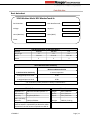
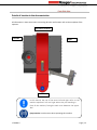
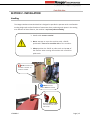
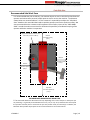
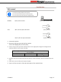
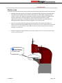
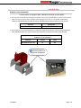
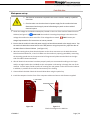
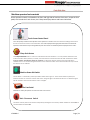
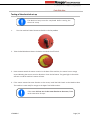
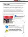
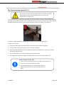
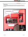
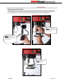
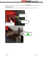
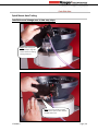

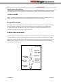
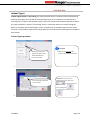
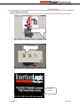
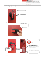
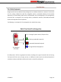
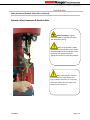
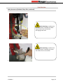
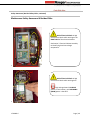
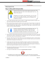
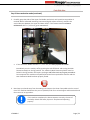
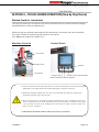
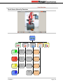
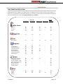
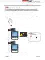
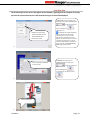
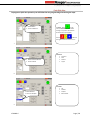
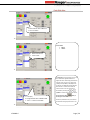
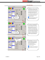
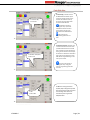
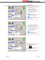
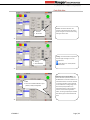
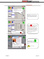
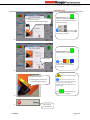
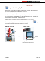
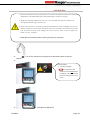
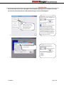
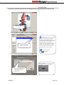
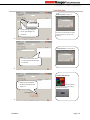
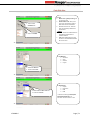
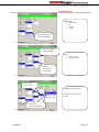
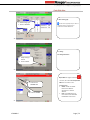
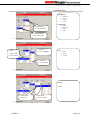
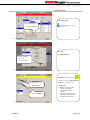
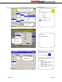
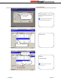
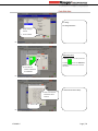
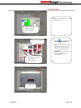
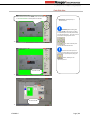
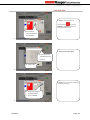
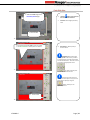
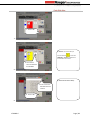
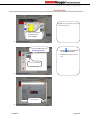
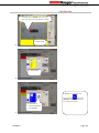
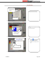
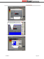
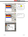
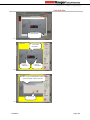
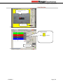
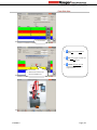
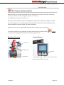
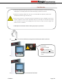
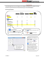
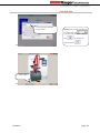
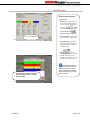
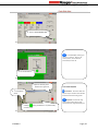
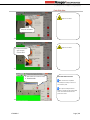
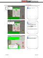
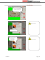
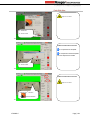
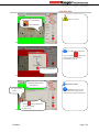
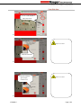
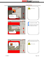
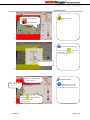
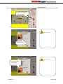
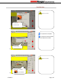
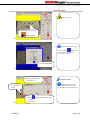
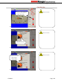
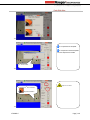
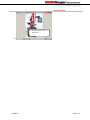
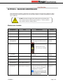

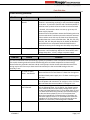
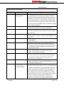
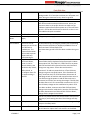
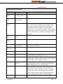
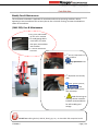
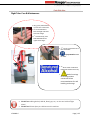
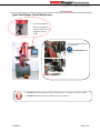
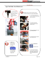
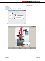
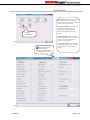
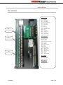
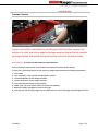
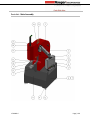
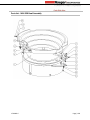
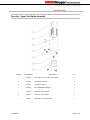
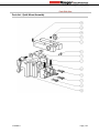
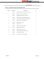
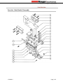
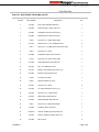
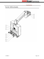
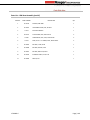
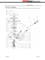
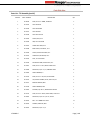
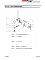
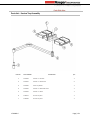
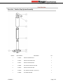
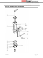
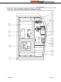
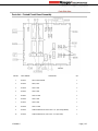
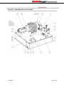
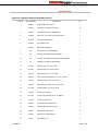
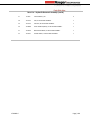
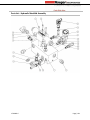
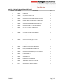
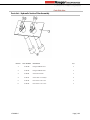
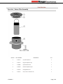
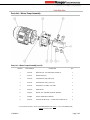
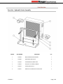
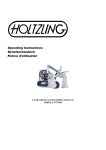


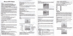

![MX2 sync [final].vp](http://vs1.manualzilla.com/store/data/005975841_1-4533d2555e3004ab9339335fb150c7a8-150x150.png)