1
RediStart TM Solid State Starter 2 SEP Synchronous Control MX SEP Models User Manual 890040-01-00 Software Version: Hardware Version: 810027-01-00 300063-01 © 2008 Benshaw Inc. Benshaw retains the right to change specifications and illustrations in text without prior notification. The contents of this document may not be copied without the explicit permission of Benshaw. BENSHAW ADVANCED CONTROLS & DRIVES Important Reader Notice 2 Congratulations on the purchase of your new Benshaw RediStart MX SEP controller. This manual contains the information to install and 2 2 program the MX SEP controller. The MX SEP controller is a standard version controller. 2 This manual may not cover all of the applications of the RediStart MX SEP. Also, it may not provide information on every possible contingency 2 concerning installation, programming, operation, or maintenance specific to the RediStart MX SEP Series Controllers. The content of this manual will not modify any prior agreement, commitment or relationship between the customer and Benshaw. The sales contract contains the entire obligation of Benshaw. The warranty enclosed within the contract between the parties is the only warranty that Benshaw will recognize and any statements contained herein do not create new warranties or modify the existing warranty in any way. Any electrical or mechanical modifications to Benshaw products without prior written consent of Benshaw will void all warranties and may also void cUL listing or other safety certifications, unauthorized modifications may also result in product damage operation malfunctions or personal injury. Incorrect handling of the controller may result with an unexpected fault or damage to the controller. For best results on operating the RediStart 2 MX SEP controller, carefully read this manual and all warning labels attached to the controller before installation and operation. Keep this manual on hand for reference. Do not attempt to install, operate, maintain or inspect the controller until you have thoroughly read this manual and related documents carefully and can use the equipment correctly. Do not use the controller until you have a full knowledge of the equipment, safety procedures and instructions. This instruction manual classifies safety instruction levels under "WARNING" and "CAUTION". Electrical Hazard that could result in injury or death. Caution that could result in damage to the starter. Highlight marking an important point in the documentation. Please follow the instructions of both safety levels as they are important to personal safety. High Voltage Motor control equipment and electronic controllers are connected to hazardous line voltages. When servicing starters and electronic controllers, there may be exposed components with housings or protrusions at or above line potential. Extreme care should be taken to protect against shock. Stand on an insulating pad and make it a habit to use only one hand when checking components. Always work with another person in case an emergency occurs. Disconnect power before checking controllers or performing maintenance. Be sure equipment is properly grounded. Wear safety glasses whenever working on electronic controllers or rotating machinery. TRADEMARK NOTICE Benshaw and are registered trademarks of Benshaw Incorporated. UL is a trademark of Underwriters Laboratories, Incorporated. SAFETY PRECAUTIONS Safety Precautions Electric Shock Prevention • • • • • • • • While power is on or controller is running, do not open the front cover. You may get an electrical shock. This controller contains high voltage which can cause electric shock resulting in personal injury or loss of life. Be sure all AC power is removed from the controller before servicing. Do not connect or disconnect the wires to or from controller when power is applied. Make sure ground connection is in place. Always install the controller before wiring. Otherwise, you may get an electrical shock or be injured. Operate the switches with dry hands to prevent an electrical shock. Risk of Electric Shock - More than one disconnect switch may be required to de-energize the equipment before servicing. Injury Prevention • • • • Service only by qualified personnel. Make sure power-up restart is off to prevent any unexpected operation of the motor. Make certain proper shield installation is in place. Apply only the voltage that is specified in this manual to the terminals to prevent damage. Transportation and Installation • • • • • • Use proper lifting gear when carrying products, to prevent injury. Make certain that the installation position and materials can withstand the weight of the controller. Refer to the installation information in this manual for correct installation. 2 If parts are missing, or controller is damaged, do not operate the RediStart MX SEP. Do not stand or rest heavy objects on the controller, as damage to the controller may result. Do not subject the controller to impact or dropping. Make certain to prevent screws, wire fragments, conductive bodies, oil or other flammable substances from entering the controller. Trial Run • Check all parameters, and ensure that the application will not be damaged by a sudden start-up. Emergency Stop • To prevent the machine and equipment from hazardous conditions if the controller fails, provide a safety backup such as an emergency brake. Disposing of the RediStart MX2 SEP • Never dispose of electrical components via incineration. Contact your state environmental agency for details on disposal of electrical components and packaging in your area. i TABLE OF CONTENTS Table of Contents 1 INTRODUCTION . . . . . . . . . . . . . . . . . . . . . . . . . . . . . . . . . . . . . . . . . . . . 2 2 TECHNICAL SPECIFICATIONS . . . . . . . . . . . . . . . . . . . . . . . . . . . . . . . . . . . 8 2.1 General Information . . . . . . . . . . . . . . . . . . . . . . . . . . . . . . . . . . . . . . . . . . . 8 2.2 Electrical Ratings . . . . . . . . . . . . . . . . . . . . . . . . . . . . . . . . . . . . . . . . . . . . . 8 2.2.1 Terminal Points and Functions. . . . . . . . . . . . . . . . . . . . . . . . . . . . . . . . . . . . . . . . 8 2.2.2 Measurements and Accuracies . . . . . . . . . . . . . . . . . . . . . . . . . . . . . . . . . . . . . . . . 9 2.2.3 List of Motor Protection Features . . . . . . . . . . . . . . . . . . . . . . . . . . . . . . . . . . . . . . 9 2.3 Environmental Conditions. . . . . . . . . . . . . . . . . . . . . . . . . . . . . . . . . . . . . . . . 10 2.4 Altitude Derating . . . . . . . . . . . . . . . . . . . . . . . . . . . . . . . . . . . . . . . . . . . . . 10 2.5 Approvals . . . . . . . . . . . . . . . . . . . . . . . . . . . . . . . . . . . . . . . . . . . . . . . . . 10 2.6 Certificate of Compliance . . . . . . . . . . . . . . . . . . . . . . . . . . . . . . . . . . . . . . . . 10 3 INSTALLATION . . . . . . . . . . . . . . . . . . . . . . . . . . . . . . . . . . . . . . . . . . . . . 12 3.1 Before You Start. . . . . . . . . . . . . . . . . . . . . . . . . . . . . . . . . . . . . . . . . . . . . . 12 3.1.1 Inspection. . . . . . . . . . . . . . . . . . . . . . . . . . . . . . . . . . . . . . . . . . . . . . . . . . . . 12 3.1.2 Installation Precautions . . . . . . . . . . . . . . . . . . . . . . . . . . . . . . . . . . . . . . . . . . . . 12 3.1.3 Safety Precautions . . . . . . . . . . . . . . . . . . . . . . . . . . . . . . . . . . . . . . . . . . . . . . . 12 3.2 Installation Considerations . . . . . . . . . . . . . . . . . . . . . . . . . . . . . . . . . . . . . . . 13 3.2.1 Site Preparation . . . . . . . . . . . . . . . . . . . . . . . . . . . . . . . . . . . . . . . . . . . . . . . . 13 3.2.2 EMC Installation Guidelines . . . . . . . . . . . . . . . . . . . . . . . . . . . . . . . . . . . . . . . . . 13 3.3 Mounting Considerations . . . . . . . . . . . . . . . . . . . . . . . . . . . . . . . . . . . . . . . . 14 3.4 Wiring Considerations . . . . . . . . . . . . . . . . . . . . . . . . . . . . . . . . . . . . . . . . . . 15 3.4.1 3.4.2 3.4.3 3.4.4 3.4.5 Wiring Practices . . . . . . . . . . . . . . . . . . Considerations for Control and Power Wiring. Considerations for Signal Wiring . . . . . . . . Meggering a Motor . . . . . . . . . . . . . . . . High Pot Testing . . . . . . . . . . . . . . . . . . . . . . . . . . . . . . . . . . . . . . . . . . . . . . . . . . . . . . . . . . . . . . . . . . . . . . . . . . . . . . . . . . . . . . . . . . . . . . . . . . . . . . . . . . . . . . . . . . . . . . . . . . . . . . . . . . . . . . . . . . . . . . . . . . . . . . . . . . . . . . . . . . . . . . . . 15 15 15 15 15 3.5 Power and Control Drawings . . . . . . . . . . . . . . . . . . . . . . . . . . . . . . . . . . . . . . 16 3.5.1 MX2 ATL Synchronous Brushtype (Field Control) Solid State. . . . . . . . . . . . . . . . . . . . . . 16 3.5.2 MX2 ATL Synchronous Brushtype with contactors . . . . . . . . . . . . . . . . . . . . . . . . . . . . 17 3.5.3 MX2 ATL Synchronous Brushless . . . . . . . . . . . . . . . . . . . . . . . . . . . . . . . . . . . . . . 18 3.6 Power Wiring . . . . . . . . . . . . . . . . . . . . . . . . . . . . . . . . . . . . . . . . . . . . . . . 19 3.6.1 3.6.2 3.6.3 3.6.4 3.6.5 Recommended Incoming Line Protection . . . . . . . . Recommended Wire Gauges . . . . . . . . . . . . . . . . Power Wire Connections . . . . . . . . . . . . . . . . . . Compression Lugs. . . . . . . . . . . . . . . . . . . . . . Torque Requirements for Power Wiring Terminations . . . . . . . . . . . . . . . . . . . . . . . . . . . . . . . . . . . . . . . . . . . . . . . . . . . . . . . . . . . . . . . . . . . . . . . . . . . . . . . . . . . . . . . . . . . . . . . . . . . . . . . . . . . . . . . . . . . . . . . . . . . . . . 19 19 19 19 20 3.7 Control Card Layout . . . . . . . . . . . . . . . . . . . . . . . . . . . . . . . . . . . . . . . . . . . 21 3.8 Control Wiring . . . . . . . . . . . . . . . . . . . . . . . . . . . . . . . . . . . . . . . . . . . . . . 22 3.8.1 3.8.2 3.8.3 3.8.4 3.8.5 Control Power . . . . . . . . . Output Relays . . . . . . . . . Digital Input Wiring Options Analog Output . . . . . . . . . SW1 DIP Switch . . . . . . . . . . . . . . . . . . . . . . . . . . . . . . . . . . . . . . . . . . . . . . . . . . . . . . . . . . . . . . . . . . . . . . . . . . . . . . . . . . . . . . . . . . . . . . . . . . . . . . . . . . . . . . . . . . . . . . . . . . . . . . . . . . . . . . . . . . . . . . . . . . . . . . . . . . . . . . . . . . . . . . . . . . . . . . . . . . . . . . . . . . . . . . . . . . . . . . . . . . . . . . . . 22 22 23 24 24 3.9 Remote LCD Keypad/Display . . . . . . . . . . . . . . . . . . . . . . . . . . . . . . . . . . . . . 25 3.9.1 Remote Display . . . . . . . . . . . . . . . . . . . . . . . . . . . . . . . . . . . . . . . . . . . . . . . . 25 3.9.2 Display Cutout . . . . . . . . . . . . . . . . . . . . . . . . . . . . . . . . . . . . . . . . . . . . . . . . . 25 3.9.3 Installing Display . . . . . . . . . . . . . . . . . . . . . . . . . . . . . . . . . . . . . . . . . . . . . . . 26 ii TABLE OF CONTENTS 4 KEYPAD OPERATION . . . . . . . . . . . . . . . . . . . . . . . . . . . . . . . . . . . . . . . . . 28 4.1 Introduction . . . . . . . . . . . . . . . . . . . . . . . . . . . . . . . . . . . . . . . . . . . . . . . . 28 4.2 Standard Keypad and Display . . . . . . . . . . . . . . . . . . . . . . . . . . . . . . . . . . . . . 28 4.3 Viewing Parameter Values for the Standard Keypad . . . . . . . . . . . . . . . . . . . . . . . . . 28 4.4 Changing Parameter Values . . . . . . . . . . . . . . . . . . . . . . . . . . . . . . . . . . . . . . . 29 4.5 Messages Displayed . . . . . . . . . . . . . . . . . . . . . . . . . . . . . . . . . . . . . . . . . . . 30 4.5.1 4.5.2 4.5.3 4.5.4 4.5.5 4.5.6 4.5.7 Power Up . . . . . . Stopped . . . . . . . Running. . . . . . . Alarm Condition. . Lockout Condition. Faulted Condition . Quick Meters . . . . . . . . . . . . . . . . . . . . . . . . . . . . . . . . . . . . . . . . . . . . . . . . . . . . . . . . . . . . . . . . . . . . . . . . . . . . . . . . . . . . . . . . . . . . . . . . . . . . . . . . . . . . . . . . . . . . . . . . . . . . . . . . . . . . . . . . . . . . . . . . . . . . . . . . . . . . . . . . . . . . . . . . . . . . . . . . . . . . . . . . . . . . . . . . . . . . . . . . . . . . . . . . . . . . . . . . . . . . . . . . . . . . . . . . . . . . . . . . . . . . . . . . . . . . . . . . . . . . . . . . . . . . . . . . . . . . . . . . . . . . . . . . . . . . . . . . . . . . . . . . . . . . . . . . . . . . . . . . . . . . . . 31 31 31 31 32 32 32 4.6 Jump Code . . . . . . . . . . . . . . . . . . . . . . . . . . . . . . . . . . . . . . . . . . . . . . . . 33 4.7 Restoring Factory Parameter Settings . . . . . . . . . . . . . . . . . . . . . . . . . . . . . . . . . 33 4.8 Resetting a Fault . . . . . . . . . . . . . . . . . . . . . . . . . . . . . . . . . . . . . . . . . . . . . 33 4.9 2x16 Remote LCD Keypad . . . . . . . . . . . . . . . . . . . . . . . . . . . . . . . . . . . . . . . . 34 4.10 Description of the LEDs on the Keypad. . . . . . . . . . . . . . . . . . . . . . . . . . . . . . . . 34 4.11 Description of the Keys on the Remote LCD Keypad . . . . . . . . . . . . . . . . . . . . . . . . 35 4.12 Alphanumeric Display . . . . . . . . . . . . . . . . . . . . . . . . . . . . . . . . . . . . . . . . . 36 4.12.1 4.12.2 4.12.3 4.12.4 4.12.5 4.12.6 Parameter Group Screens Meter Pages . . . . . . . . Fault Log Screen . . . . . Fault Screen . . . . . . . . Lockout Screen . . . . . . Alarm Screen . . . . . . . . . . . . . . . . . . . . . . . . . . . . . . . . . . . . . . . . . . . . . . . . . . . . . . . . . . . . . . . . . . . . . . . . . . . . . . . . . . . . . . . . . . . . . . . . . . . . . . . . . . . . . . . . . . . . . . . . . . . . . . . . . . . . . . . . . . . . . . . . . . . . . . . . . . . . . . . . . . . . . . . . . . . . . . . . . . . . . . . . . . . . . . . . . . . . . . . . . . . . . . . . . . . . . . . . . . . . . . . . . . . . . . . . . . . . . . . . . . . . . . . . . . . . . . . . . . . 37 38 38 39 39 39 4.13 Procedure for Setting Data . . . . . . . . . . . . . . . . . . . . . . . . . . . . . . . . . . . . . . . 40 5 PARAMETER GROUPS . . . . . . . . . . . . . . . . . . . . . . . . . . . . . . . . . . . . . . . . . 44 5.1 Introduction . . . . . . . . . . . . . . . . . . . . . . . . . . . . . . . . . . . . . . . . . . . . . . . . 44 5.2 LED and LCD Display Parameters Cross Reference & Control Mode Reference . . . . . . . . . 45 5.3 LED Display Parameters . . . . . . . . . . . . . . . . . . . . . . . . . . . . . . . . . . . . . . . . . 46 5.4 LCD Display Parameters. . . . . . . . . . . . . . . . . . . . . . . . . . . . . . . . . . . . . . . . . 49 5.4.1 5.4.2 5.4.3 5.4.4 5.4.5 5.4.6 5.4.7 Quick Start Group . . . . Control Function Group Protection Group . . . . I/O Group . . . . . . . . Function Group . . . . . LCD Fault Group . . . . LED Fault Group . . . . . . . . . . . . . . . . . . . . . . . . . . . . . . . . . . . . . . . . . . . . . . . . . . . . . . . . . . . . . . . . . . . . . . . . . . . . . . . . . . . . . . . . . . . . . . . . . . . . . . . . . . . . . . . . . . . . . . . . . . . . . . . . . . . . . . . . . . . . . . . . . . . . . . . . . . . . . . . . . . . . . . . . . . . . . . . . . . . . . . . . . . . . . . . . . . . . . . . . . . . . . . . . . . . . . . . . . . . . . . . . . . . . . . . . . . . . . . . . . . . . . . . . . . . . . . . . . . . . . . . . . . . . . . . . . . . . . . . . . . . . . . . . . . . . . . . . . . . . . . . . . 49 50 50 51 52 53 53 6 PARAMETER DESCRIPTION . . . . . . . . . . . . . . . . . . . . . . . . . . . . . . . . . . . . . 56 6.1 Parameter Descriptions . . . . . . . . . . . . . . . . . . . . . . . . . . . . . . . . . . . . . . . . . 56 7 THEORY OF OPERATION . . . . . . . . . . . . . . . . . . . . . . . . . . . . . . . . . . . . . . . 86 7.1 Control Modes of Synchronous Motor Operation . . . . . . . . . . . . . . . . . . . . . . . . . . . 86 7.1.1 Brush Type (Field Control) Synchronous Motor Operation . . . . . . . . . . . . . . . . . . . . . . . 86 7.1.2 Brushless Type Synchronous Motor Operation . . . . . . . . . . . . . . . . . . . . . . . . . . . . . . 87 7.1.3 Current Follower . . . . . . . . . . . . . . . . . . . . . . . . . . . . . . . . . . . . . . . . . . . . . . . 87 7.2 Use Hall Effect Current Sensor . . . . . . . . . . . . . . . . . . . . . . . . . . . . . . . . . . . . . 88 7.2.1 Analog Input . . . . . . . . . . . . . . . . . . . . . . . . . . . . . . . . . . . . . . . . . . . . . . . . . . 88 iii TABLE OF CONTENTS 7.3 Simplified I/O Schematics. . . . . . . . . . . . . . . . . . . . . . . . . . . . . . . . . . . . . . . . 90 7.4 Remote Modbus Communications . . . . . . . . . . . . . . . . . . . . . . . . . . . . . . . . . . . 91 7.4.1 7.4.2 7.4.3 7.4.4 7.4.5 7.4.6 7.4.7 Supported Commands . . . Modbus Register Addresses Cable Specifications . . . . . Terminating Resistors . . . . Grounding . . . . . . . . . . Shielding . . . . . . . . . . . Wiring. . . . . . . . . . . . . . . . . . . . . . . . . . . . . . . . . . . . . . . . . . . . . . . . . . . . . . . . . . . . . . . . . . . . . . . . . . . . . . . . . . . . . . . . . . . . . . . . . . . . . . . . . . . . . . . . . . . . . . . . . . . . . . . . . . . . . . . . . . . . . . . . . . . . . . . . . . . . . . . . . . . . . . . . . . . . . . . . . . . . . . . . . . . . . . . . . . . . . . . . . . . . . . . . . . . . . . . . . . . . . . . . . . . . . . . . . . . . . . . . . . . . . . . . . . . . . . . . . . . . . . . . . . . . . . . . . . . . . . . . . . . . . . . . . . . . . . . . . . . . 91 91 91 91 91 91 92 7.5 Dynamic Braking . . . . . . . . . . . . . . . . . . . . . . . . . . . . . . . . . . . . . . . . . . . . . 94 8 TROUBLESHOOTING & MAINTENANCE . . . . . . . . . . . . . . . . . . . . . . . . . . . . . 96 8.1 Safety Precautions . . . . . . . . . . . . . . . . . . . . . . . . . . . . . . . . . . . . . . . . . . . . 96 8.2 Preventative Maintenance . . . . . . . . . . . . . . . . . . . . . . . . . . . . . . . . . . . . . . . . 96 8.2.1 General Information. . . . . . . . . . . . . . . . . . . . . . . . . . . . . . . . . . . . . . . . . . . . . . 96 8.2.2 Preventative Maintenance . . . . . . . . . . . . . . . . . . . . . . . . . . . . . . . . . . . . . . . . . . 96 8.3 General Troubleshooting Charts . . . . . . . . . . . . . . . . . . . . . . . . . . . . . . . . . . . . 97 8.3.1 8.3.2 8.3.3 8.3.4 8.3.5 Motor does not start, no output to motor . . . . . . . . . . . . During starting, motor rotates but does not reach full speed Motor stops unexpectedly while running . . . . . . . . . . . Metering incorrect (Hall Effect) . . . . . . . . . . . . . . . . . Other Situations . . . . . . . . . . . . . . . . . . . . . . . . . . . . . . . . . . . . . . . . . . . . . . . . . . . . . . . . . . . . . . . . . . . . . . . . . . . . . . . . . . . . . . . . . . . . . . . . . . . . . . . . . . . . . . . . . . . . . . . . . . . . . . . . . . . . . . . . 97 98 98 99 100 8.4 Fault Code Table . . . . . . . . . . . . . . . . . . . . . . . . . . . . . . . . . . . . . . . . . . . . . 101 8.5 SCR Testing . . . . . . . . . . . . . . . . . . . . . . . . . . . . . . . . . . . . . . . . . . . . . . . . 106 8.5.1 Resistance. . . . . . . . . . . . . . . . . . . . . . . . . . . . . . . . . . . . . . . . . . . . . . . . . . . . 106 8.5.2 Voltage . . . . . . . . . . . . . . . . . . . . . . . . . . . . . . . . . . . . . . . . . . . . . . . . . . . . . 106 8.6 Field Discharge Resistor Sizing . . . . . . . . . . . . . . . . . . . . . . . . . . . . . . . . . . . . . 106 8.7 Built In Self Test Functions . . . . . . . . . . . . . . . . . . . . . . . . . . . . . . . . . . . . . . . 107 8.7.1 Powered BIST Tests: . . . . . . . . . . . . . . . . . . . . . . . . . . . . . . . . . . . . . . . . . . . . . 107 8.8 SCR Replacement . . . . . . . . . . . . . . . . . . . . . . . . . . . . . . . . . . . . . . . . . . . . . 108 8.8.1 8.8.2 8.8.3 8.8.4 8.8.5 8.8.6 Typical Stack Assembly. SCR Removal. . . . . . . SCR Installation . . . . . SCR Clamp . . . . . . . . Tightening Clamp . . . . Testing SCR. . . . . . . . . . . . . . . . . . . . . . . . . . . . . . . . . . . . . . . . . . . . . . . . . . . . . . . . . . . . . . . . . . . . . . . . . . . . . . . . . . . . . . . . . . . . . . . . . . . . . . . . . . . . . . . . . . . . . . . . . . . . . . . . . . . . . . . . . . . . . . . . . . . . . . . . . . . . . . . . . . . . . . . . . . . . . . . . . . . . . . . . . . . . . . . . . . . . . . . . . . . . . . . . . . . . . . . . . . . . . . . . . . . . . . . . . . . . . . . . . . . . . . . . . . . . . . . . . . . . . . . . . . 108 108 108 109 109 109 APPENDIX A ALARM CODES . . . . . . . . . . . . . . . . . . . . . . . . . . . . . . . . . . . . . 112 APPENDIX B FAULT CODES . . . . . . . . . . . . . . . . . . . . . . . . . . . . . . . . . . . . . . 114 APPENDIX C SPARE PARTS . . . . . . . . . . . . . . . . . . . . . . . . . . . . . . . . . . . . . . 115 APPENDIX D EU DECLARATION OF CONFORMITY . . . . . . . . . . . . . . . . . . . . . . . 116 APPENDIX E MODBUS REGISTER MAP . . . . . . . . . . . . . . . . . . . . . . . . . . . . . . . 117 APPENDIX F PARAMETER TABLES . . . . . . . . . . . . . . . . . . . . . . . . . . . . . . . . . . 122 iv 1 Introduction 1 1 - INTRODUCTION INTRODUCTION 1 Using this Manual Layout This manual is divided into 10 sections. Each section contains topics related to the section. The sections are as follows: • Introduction • • • • • • • • • Symbols Technical Information Installation Keypad Operation Parameters Parameter Description Applications Theory of Operation Troubleshooting & Maintenance Appendices There are 2 symbols used in this manual to highlight important information. The symbols appear as the following: Electrical Hazard warns of situations in which a high voltage can cause physical injury, death and/or damage equipment. Caution warns of situations in which physical injury and/damage to equipment may occur by means other than electrical. Highlight mark an important point in the documentation. DANGER HAZARD OF ELECTRIC SHOCK, EXPLOSION, OR ARC FLASH Only qualified personnel familiar with low voltage equipment are to perform work described in this set of instructions. Apply appropriate personal protective equipment (PPE) and follow safe electrical work practices. See NFPA 70E. Turn off all power before working on or inside equipment. Use a properly rated voltage sensing device to confirm that the power is off. Before performing visual inspections, tests, or maintenance on the equipment, disconnect all sources of electric power. Assume that circuits are live until they have been completely de-energized, tested, and tagged. Pay particular attention to the design of the power system. Consider all sources of power, including the possibility of backfeeding. Replace all devices, doors, and covers before turning on power to this equipment. Failure to follow these instructions will result in death or serious injury. 2 1 - INTRODUCTION Benshaw Services General Information Benshaw offers its customers the following: • Start-up services • • • • On-site training services Technical support Detailed documentation Replacement parts z NOTE: Information about products and services is available by contacting Benshaw, refer to page 4. Start-Up Services Benshaw technical field support personnel are available to customers with the initial start-up of the 2 RediStart MX SEP. Information about start-up services and fees are available by contacting Benshaw. On-Site Training Services Benshaw technical field support personnel are available to conduct on-site training on RediStart MX SEP operations and troubleshooting. Technical Support Benshaw technical support personnel are available (at no charge) to answer customer questions and provide technical support over the telephone. For more information about contacting technical support personnel, refer to page 4. Documentation Benshaw provides all customers with: • Operations manual. • 2 Wiring diagram. All drawings are produced in AutoCAD© format. The drawings are available on standard CD / DVD or via e-mail by contacting Benshaw. 2 On-Line Documentation All RediStart MX SEP documentation is available on-line at http://www.benshaw.com. Replacement Parts Spare and replacement parts can be purchased from Benshaw Technical Support. Software Number This manual pertains to the software version numbers 810027-01-00. Hardware Number This manual pertains to the hardware version numbers 300063-01. Publication History See page 127. Warranty Benshaw provides a 1 year standard warranty with its controllers. An extension to the 3 year warranty is provided when a Benshaw or Benshaw authorized service technician completes the installation and initial start up. The warranty data sheet must also be signed and returned. The cost of this service is not included in the price of the Benshaw controllers and will be quoted specifically to each customers needs. All recommended maintenance procedures must be followed throughout the warranty period to ensure validity. This information is also available by going online to register at www.benshaw.com. 3 1 - INTRODUCTION Contacting Benshaw Contacting Benshaw Information about Benshaw products and services is available by contacting Benshaw at one of the following offices: Benshaw Inc. Corporate Headquarters 1659 E. Sutter Road Glenshaw, PA 15116 Phone: (412) 487-8235 Tech Support: (800) 203-2416 Fax: (412) 487-4201 Benshaw High Point EPC Division 645 McWay Drive High Point, NC 27263 Phone: (336) 434-4445 Fax: (336) 434-9682 Benshaw Canada Controls Inc. Benshaw Mobile 550 Bright Street East Listowel, Ontario N4W 3W3 Phone: (519) 291-5112 Tech Support: (877) 236-7429 (BEN-SHAW) Fax: (519) 291-2595 CSD Division 5821 Rangeline Road, Suite 202 Theodor, AL 36582 Phone: (251) 443-5911 Fax: (251) 443-5966 Benshaw West Benshaw Pueblo 14715 North 78th Way, Suite 600 Scottsdale, AZ 85260 Phone: (480) 905-0601 Fax: (480) 905-0757 Trane Division 1 Jetway Court Pueblo, CO 81001 Phone: (719) 948-1405 Fax: (719) 948-1445 2 Technical support for the RediStart MX SEP Series is available at no charge by contacting Benshaw’s customer service department at one of the above telephone numbers. A service technician is available Monday through Friday from 8:00 a.m. to 5:00 p.m. EST. z NOTE: An on-call technician is available after normal business hours and on weekends by calling Benshaw and following the recorded instructions. To help assure prompt and accurate service, please have the following information available when contacting Benshaw: • Name of Company • • • • • • • • • • • 4 Telephone number where the caller can be contacted Fax number of caller Benshaw product name Benshaw model number Benshaw serial number Name of product distributor Approximate date of purchase Voltage of motor attached to Benshaw product FLA of motor attached to Benshaw product A brief description of the application Field voltage and current rating of motor 1 - INTRODUCTION Interpreting Model Numbers Figure 1: RediStart MX2 SEP Series Model Numbers MX2SEP-125VDC-50A-3-S-C C = Open Chassis S = Solid State M = Mechanical (contactors) 1 = Single phase bridge 3 = Three phase bridge Current Rating of Bridge Voltage rating of field (125 or 250 VDC) MX2 Control Example of Model Number: MX2SEP-125VDC-50A-3-S-C 2 A Controller with 125VDC field voltage, MX SEP control, 50A at bridge, 3 phase bridge, solid-state ,open Chassis. 5 1 - INTRODUCTION General Overview of a Synchronous Field Controller 2 General Overview • • • • The RediStart MX SEP synchronous field controller is a microprocessor based controller for single or three-phase field supply. The sync controller can be custom designed for specific applications. A few of the features are: Solid state design. Closed-loop current control. Programmable operating parameters. Programmable metering. 2 Each MX SEP can operate within applied line voltage and frequency values of 100VAC to 600VAC (optional 1000VAC) and 23 to 72Hz. 2 The field controller can be programmed for synchronous motor fields. The RediStart MX SEP can also protect the motor and its load from damage that could be caused by incorrect phase order wiring. The controller continually monitors the amount of field current being delivered to the motor. This protects the motor from overheating or drawing excess current. Features • • • • • • • • • • • • • 6 The enhanced engineering features of the starter include: Multiple frame sizes Universal voltage operation Universal frequency operation Phase rotation protection Regulated current control Electronic over/under current protection Single phase protection Programmable metering Passcode protected Programmable Relays Analog output with digital offset and span adjustment Analog input with digital offset and span adjustment Voltage and Current Accuracy of 3% 2 Technical Specifications 2 - TECHNICAL SPECIFICATIONS TECHNICAL 2 SPECIFICATIONS Technical Specifications 2.1 General Information The physical specifications of the starter vary depending upon its configuration. The applicable motor current determines the configuration and its specific application requirements. Specifications are subject to change without notice. This document covers the control electronics and several power sections: 2 • MX SEP control card • RC Power Stacks, Continuous operation, NO bypass Electrical Ratings 2.2 Electrical Ratings 2.2.1 Terminal Points and Functions Table 1: Terminals Function Terminal Block Terminal Number Description Control Power TB1 G, ground N, 120VAC neutral N, 120VAC neutral L, 120VAC line L, 120VAC line 96 – 144 VAC input, 50/60 Hz 45VA required for control card Relay 1 (R1) TB2 NO1:Normally Open Contact RC1:Common NC1: Normally Closed Contact Relay Output, SPDT form C NO Contact (resistive) 5A at 250VAC 5A at 125VAC 5A at 30VDC 1250VA NC Contact(resistive) 3A at 250VAC 3A at 125VAC 3A at 30VDC 750VA NO2: Normally Open Contact RC2: Common Contact NC2: Normally Closed Contact Relay Output, SPDT form C NO Contact (resistive) 5A at 250VAC 5A at 125VAC 5A at 30VDC 1250VA NC Contact(resistive) 3A at 250VAC 3A at 125VAC 3A at 30VDC 750VA Relay 2 (R2) TB2 Relay 3 (R3) TB2 NO3: Normally Open Contact RC3: Common Contact NC3: Normally Closed Contact 10A at 250VAC 10A at 125VAC 10A at 30VDC 2500VA Digital Inputs TB3 1: Start 2: DI1 3: DI2 4: DI3 5: Common 120VAC digital input 2500V optical isolation 4mA current draw Off: 0-35VAC On: 60-120VAC Serial Comm TB4 1: B+ 2: A3: COM Modbus RTU serial communication port. RS-485 interface 19.2k baud maximum 2500V Isolation Analog I/O (Hall Effect input) TB5 1: Ain Power 2: M 3: Common 4: Ground (Sheild) 5: Aout 6: Common 7: Shield Input: Voltage or Current Voltage: 0-10VDC, 67KW impedance Current: 0-20mA, 500W impedance Display 8 RJ45 Output: Voltage or Current Voltage: 0-10VDC, 120mA maximum Current: 0-20mA, 500W load maximum Door Mounted Display Connector 2 - TECHNICAL SPECIFICATIONS Table 1: Terminals Terminal Block Function SCR Terminal Number J6 to J11 1: Gate 2: Cathode Description SCR gate Connections Wire Gauge: The terminals can support 1- 14 AWG wire or 2-16 AWG wire or smaller. Torque Rating: The terminals on the control card have a torque rating of 5.0-inch lb. or 0.56Nm. This MUST be followed or damage will occur to the terminals. Refer to the Control Card Layout on page 21. 2.2.2 Measurements and Accuracies Table 2: Measurements and Accuracies Internal Measurements Hall Effect Input Line Voltage Inputs Conversion: True RMS, Sampling @ 1.562kHz Range: 1-1000A Conversion: True RMS, Sampling @ 1.562kHz Range: 100VAC to 1000VAC 23 to 72 Hz Metering Current Slip % Voltage Line Frequency Run Time Analog Input Analog Output 2.2.3 0 – 40,000 Amps ± 3% 0.0 – 100% 0 – 1250 Volts ± 3% 23 – 72 Hz ± 0.1 Hz ± 3 seconds per 24 hour period Accuracy ± 3% of full scale (10 bit) Accuracy ±2% of full scale (12 bit) z NOTE: Percent accuracy is percent of full scale of the given ranges, Current = Current Setpoint, Voltage = 1000V List of Motor Protection Features • • • • • • • • • • • • • ANSI 27 / 59 – Adjustable over/under voltage protection (Off or 1 to 40%, time 0.1 to 90.0 sec. in 0.1 sec. intervals, independent over and under voltage levels) ANSI 37 – Undercurrent detection (Off or 5 to 100% and time 0.1 to 90.0 sec. in 0.1 sec. intervals) ANSI 47 – Phase rotation (selectable ABC, CBA, Insensitive, or Single Phase) ANSI 48 – Incomplete Sequence ANSI 51 – Overcurrent detection (Off or 50 to 800% and time 0.1 to 90.0 sec. in 0.1 sec. intervals) ANSI 56 – Field Application ANSI 74 – Alarm relay output available ANSI 81 – Over / Under Frequency ANSI 94 – Tripping ANSI 95 – Reluctance torque sync ANSI 96 – Autoloading Single Phase Protection Shorted SCR detection 9 2 - TECHNICAL SPECIFICATIONS Environmental Conditions 2.3 Environmental Conditions Table 4: Environmental Ratings Operating Temperatures -10°C to +40°C (14°F to 104°F)enclosed -10°C to +50°C (14°F to 122°F)open Storage Temperatures -20°C to +70°C (-4°F to 155°F) Humidity 0% to 95% non condensing Altitude 1000m (3300ft) without derating Maximum Vibration 5.9m/s2 (19.2ft/s2 ) [0.6G] Cooling (Natural convection) or Fan Forced Altitude Derating 2.4 Altitude Derating Benshaw's starters are capable of operating at altitudes up to 3,300 feet (1000 meters) without requiring altitude derating. Table 3 provides the derating percentage to be considered when using a starter above 3,300 feet (1000 meters). Table 3: Altitude Derating Altitude Percent Derating (Amps) 3300 Feet 1006 meters 0.0% 4300 Feet 1311 meters 3.0% 5300 Feet 1615 meters 6.0% 6300 Feet 1920 meters 9.0% 7300 Feet 2225 meters 12.0% 8300 Feet 2530 meters 15.0% 9300 Feet 2835 meters 18.0% For derating above 10,000 feet consult Benshaw Inc. Approvals 2.5 Approvals 2 MX SEP Control Card is UL, cUL Recognized Certificate of Compliance 2.6 Certificate of Compliance CE Mark, See Appendix D on page 116. 10 3 Installation 3 - INSTALLATION INSTALLATI 3 ON Before You Start 3.1 Before You Start 3.1.1 Inspection 2 Before storing or installing the RediStart MX SEP Series sync controller, thoroughly inspect the device for possible shipping damage. Upon receipt: • Remove the controller from its package and inspect exterior for shipping damage. If damage is apparent, notify the shipping agent and your sales representative. • Open the enclosure and inspect the controller for any apparent damage or foreign objects. Ensure that all of the mounting hardware and terminal connection hardware is properly seated, securely fastened, and undamaged. • Ensure all connections and wires are secured. • Read the technical data label affixed to the controller and ensure that the correct amperage and input voltage for the application has been purchased. • The numbering system for a chassis is shown below. 3.1.2 Installation Precautions Installation of some models may require halting production during installation. If applicable, ensure that the controller is installed when production can be halted long enough to accommodate the installation. Before installing the controller, ensure: • The wiring diagram (supplied separately with the controller) is correct for the required application. • The controller is the correct current rating and voltage rating for the motor.. • All of the installation safety precautions are followed. • The correct power source is available. • The starter control method has been selected. • The connection cables have been obtained (lugs and associated mounting hardware. • The necessary installation tools and supplies are procured. • The installation site meets all environmental specifications for the starter NEMA/CEMA rating. • The motor being started has been installed and is ready to be started. 3.1.3 Safety Precautions To ensure the safety of the individuals installing the sync controller, and the safe operation of the starter, observe the following guidelines: • Ensure that the installation site meets all of the required environmental conditions (Refer to Site Preparation, page 13). • LOCK OUT ALL SOURCES OF POWER. • Install circuit disconnecting devices (i.e., circuit breaker, fused disconnect or non-fused disconnect) if they were not previously installed by the factory as part of the package. • Install short circuit protection (i.e., circuit breaker or fuses) if not previously installed by the factory as part of the package. • Consult Power Ratings for the fault rating on pages 19. • Follow all NEC (National Electrical Code) and/or C.S.A. (Canadian Standards Association) standards or Local Codes as applicable. • Remove any foreign objects from the interior of the enclosure, especially wire strands that may be left over from installation wiring. • Ensure that a qualified electrician installs wiring. • Ensure that the individuals installing the controller are wearing ALL protective eyewear and clothing. • Ensure the controller is protected from debris, metal shavings and any other foreign objects. The opening of the branch circuit protective device may be an indication that a fault current has been interrupted. To reduce the risk of electrical shock, current carrying parts and other components of the controller should be inspected and replaced if damaged. 12 3 - INSTALLATION Installation Considerations 3.2 Installation Considerations 3.2.1 Site Preparation General Information Before the sync controller can be installed, the installation site must be prepared. The customer is responsible for: • Providing the correct power source. • Providing the correct power protection. • Selecting the control mechanism. • Obtaining the connection cables, lugs and all other hardware • Ensuring the installation site meets all environmental specifications for the enclosure NEMA rating. • Installing and connecting the motor. Power Cables The power cables for the controller must have the correct NEC/CSA current rating for the unit being installed. Depending upon the model, the power cables can range from a single #14 AWG conductor to four 750 MCM cables. (Consult local and national codes for selecting wire size). Site Requirements The installation site must adhere to the applicable contrtoller NEMA/CEMA rating. For optimal performance, the installation site must meet the appropriate environmental and altitude requirements. 3.2.2 EMC Installation Guidelines General In order to help our customers comply with European electromagnetic compatibility standards, Benshaw Inc. has developed the following guidelines. Attention This product has been designed for Class A equipment. Use of the product in domestic environments may cause radio interference, in which case the installer may need to use additional mitigation methods. Enclosure Install the product in a grounded metal enclosure. Grounding Connect a grounding conductor to the screw or terminal provided as standard on each controller. Refer to layout/power wiring schematic for grounding provision location. Wiring Refer to Wiring Practices on page 15. Filtering To comply with Conducted Emission Limits (CE requirement), a high voltage (1000V or greater) 0.1 uF capacitor should be connected from each input line to ground at the point where the line enters the cabinet. 13 3 - INSTALLATION Mounting Considerations 3.3 Mounting Considerations Provisions should be made to ensure that the temperature inside the enclosure never rises above 50°C. If the temperature inside the enclosure is too high, the starter can be damaged or the operational life can be reduced. As a general rule of thumb, the following ventilation guidelines can be followed. Table 5: Ventilation Requirements Current Range < 200 amps 200 to 300 amps 301 to 400 amps 401 to 600 amps 601 to 700 amps > 700 amps Bottom of Enclosure Fans or grills depending on enclosure size 2 x 4” grills (12 sq. in.) 1 x 4” fan (115 cfm) 2 x 4” fan (230 cfm) 2 x 6” fan (470 cfm) Consult factory Top of Enclosure 2 x 4” grills (12 sq.in.) 2 x 4” grills (12 sq.in.) 2 x 6” grills (28 sq.in.) 2 x 6” grills (28 sq.in.) Consult Factory The field supply produces 4 watts of heat per amp of current and 26 square inches of enclosure surface is required per watt of heat generation. Contact Benshaw and ask for the enclosure sizing technical note for more information concerning starters in sealed enclosures. Benshaw supplies starters under 124 amps non-bypassed, with the heat sink protruding from the back of the enclosure. This allows a small enclosure size while still maintaining the cooling capability of the starter. 14 3 - INSTALLATION Wiring Considerations 3.4 Wiring Considerations 3.4.1 Wiring Practices When making power and control signal connections, the following should be observed: • Power wiring to the motor must have the maximum possible separation from all other wiring. Do not run control wiring in the same conduit; this separation reduces the possibility of coupling electrical noise between circuits. Minimum spacing between metallic conduits containing different wire groups should be three inches (8cm). • Minimum spacing between different wiring groups in the same tray should be six inches. • Wire runs outside an enclosure should be run in metallic conduit or have shielding/armor with equivalent attenuation. • Whenever power and control wiring cross it should be at a 90 degrees angle. • Different wire groups should be run in separate conduits. z NOTE: Local electrical codes must be adhered to for all wiring practices. 3.4.2 Considerations for Control and Power Wiring Control wiring refers to wires connected to the control terminal strip that normally carry 24V to 115V and Power wiring refers to wires connected to the line and load terminals that normally carries 208VAC - 600VAC respectively. Select power wiring as follows: • Use only UL or CSA recognized wire. • Wire voltage rating must be a minimum of 300V for 230VAC systems and 600V (Class 1 wire) for 460VAC and 600VAC systems. • Grounding must be in accordance with NEC, CEC or local codes. If multiple starters are installed near each other, each must be connected to ground. Take care to not form a ground loop. The grounds should be connected in a STAR configuration. • Wire must be made of copper and rated 60/75°C for units 124 Amps and below. Larger amp units may use copper or aluminum wire. Refer to NEC table 310-16 or local codes for proper wire selection. 3.4.3 Considerations for Signal Wiring Signal wiring refers to the wires connected to the control terminal strip that are low voltage signals, below 15V. • Shielded wire is recommended to prevent electrical noise interference from causing improper operation or nuisance tripping. • Signal wire rating should carry as high of a voltage rating as possible, normally at least 300V. • Routing of signal wire is important to keep as far away from control and power wiring as possible. 3.4.4 Meggering a Motor If the motor needs to be meggered, remove the motor leads from the sync controller before conducting the test. Failure to comply may damage the SCRs and WILL damage the control board, which WILL NOT be replaced under warranty. 3.4.5 High Pot Testing If the sync controller needs to be high pot tested, perform a DC high pot test. The maximum high point voltage must not exceed 2.0 times rated RMS voltage + 1000VAC (High pot to 75% of factory). Failure to comply WILL damage the control board, which WILL NOT be replaced under warranty. An example to find the high point voltage is (2.0 * rated RMS voltage + 1000VAC) * 0.75. 15 3 - INSTALLATION Power and Control Drawings 3.5 Power and Control Drawings 3.5.1 MX2 ATL Synchronous Brushtype (Field Control) Solid State 16 H2 X2 H1 X1 MX² CARD BIPC-300063-01-XX Figure 2: Power Schematic for RB2 Low HP 3 - INSTALLATION MX2 ATL Synchronous Brushtype with contactors H2 X2 X1 MX² CARD BIPC-300063-01-XX Figure 3: MX2 ATL Synchronous Brushtype with contactors H1 3.5.2 17 3 - INSTALLATION 3.5.3 MX2 ATL Synchronous Brushless 18 H2 X2 H1 X1 MX² CARD BIPC-300063-01-XX Figure 4: MX2 ATL Synchronous Brushless 3 - INSTALLATION Power Wiring 3.6 Power Wiring 3.6.1 Recommended Incoming Line Protection A semi-conductor fuse is needed. The fuse shall be 150% of the DC Field Amps from motor. A HCJ fuse is recommended. Input Line Requirements The input line source needs to be an adequate source, generally 2 times the rating of the motor rotor FLA. (This may not apply in some cases such as being connected to a generator). 3.6.2 Recommended Wire Gauges The wire gauge selection is based on the rotor FLA of the motor. Refer to NEC table 310-16 or CEC Part 1, Table 2 or local code requirements for selecting the correct wire sizing. Ensure appropriate wire derating for temperature is applied. If more than three current carrying conductors are in one conduit, ensure NEC table 310.15(B)(2) or CEC Part 1 Table 5C is adhered to. In some areas local codes may take precedence over the NEC. Refer to your local requirements. 3.6.3 Power Wire Connections Attach the motor cables: • Use the F+ and F- terminals. Use lugs/crimps or terminals (Lugs and Crimps are to be provided by the user). Attach the power source cables: • Use the L1, L2 and L3 terminals. Use lugs/crimps or terminals (Lugs and Crimps are to be provided by the user). 3.6.4 Compression Lugs The following is a list of the recommended crimp-on wire connectors manufactured by Penn-Union Corp. for copper wire. Table 7: Single Hole Compression Lugs Wire Size 1/0 2/0 3/0 4/0 250 MCM 300 MCM 350 MCM 400 MCM 450 MCM Part # BLU-1/0S20 BLU-2/0S4 BLU-3/0S1 BLU-4/0S1 BLU-025S BLU-030S BLU-035S BLU-040S4 BLU-045S1 Wire Size 500 MCM 600 MCM 650 MCM 750 MCM 800 MCM 1000 MCM 1500 MCM 2000 MCM Part # BLU-050S2 BLU-060S1 BLU-065S5 BLU-075S BLU-080S BLU-100S BLU-150S BLU-200s Table 6: Two Hole Compression Lugs Wire Size 1/0 2/0 3/0 4/0 250 MCM 300 MCM 350 MCM 400 MCM 450 MCM Part # BLU-1/0D20 BLU-2/0D4 BLU-3/0D1 BLU-4/0D1 BLU-025D BLU-030D BLU-035D BLU-040D4 BLU-045D1 Wire Size 500 MCM 600 MCM 650 MCM 750 MCM 800 MCM 1000 MCM 1500 MCM 2000 MCM Part # BLU-050D2 BLU-060D1 BLU-065D5 BLU-075D BLU-080D BLU-100D BLU-150D BLU-200D 19 3 - INSTALLATION 3.6.5 Torque Requirements for Power Wiring Terminations Table 9: Slotted Screws and Hex Bolts Tightening torque, pound-inches (N-m) Wire size installed in conductor Hexagonal head-external drive socket wrench Slotted head NO. 10 and larger Slot width-0.047 inch Slot width-over 0.047 (1.2mm) or less and inch (1.2mm) or slot Split- bolt connectors slot length ¼ inch length – over ¼ inch (6.4mm) or less (6.4mm) or less AWG or kcmil (mm2 ) 18 – 10 (0.82 – 5.3) 20 (2.3) 35 (4.0) 80 (9.0) 75 8 (8.4) 25 (2.8) 40 (4.5) 80 (9.0) 75 (8.5) 6–4 (13.3 – 21.2) 35 (4.0) 45 (5.1) 165 (18.6) 110 (12.4) 3 (26.7) 35 (4.0) 50 (5.6) 275 (31.1) 150 (16.9) 2 (33.6) 40 (4.5) 50 (5.6) 275 (31.1) 150 (16.9) 1 (42.4) — — 50 (5.6) 275 (31.1) 150 (16.9) 1/0 – 2/0 (53.5 – 64.4) — — 50 (5.6) 385 (43.5) 180 (20.3) Other connectors (8.5) 3/0 – 4/0 (85.0 – 107.2) — — 50 (5.6) 500 (56.5) 250 (28.2) 250 – 350 (127 – 177) — — 50 (5.6) 650 (73.4) 325 (36.7) 400 (203) — — 50 (5.6) 825 (93.2) 375 (36.7) 500 (253) — — 50 (5.6) 825 (93.2) 375 (42.4) 600 – 750 (304 – 380) — — 50 (5.6) 1000 (113.0) 375 (42.4) 800 – 1000 (406 – 508) — — 50 (5.6) 1100 (124.3) 500 (56.5) 1250 – 2000 (635 – 1010) — — — — 1100 (124.3) 600 (67.8) z NOTE – For a value of slot width or length not corresponding to those specified above, the largest torque value associated with the conductor size shall be marked. Slot width is the nominal design value. Slot length is measured at the bottom of the slot. Table 8: Tightening Torque for Inside Hex Screws Socket size across flats Tightening torque inches (mm) Pound-inches (N-m) 1/8 (3.2) 45 (5.1) 5/32 (4.0) 100 (11.3) 3/16 (4.8) 120 (13.6) 7/32 (5.6) 150 (16.9) 1/4 (6.4) 200 (22.6) 5/16 (7.9) 275 (31.1) 3/8 (9.5) 275 (42.4) 1/2 (12.7) 500 (56.5) 9/16 (14.3) 600 (67.8) z NOTE – For screws with multiple tightening means, the largest torque value associated with the conductor size shall be marked. Slot length shall be measured at the bottom of the slot. 20 3 - INSTALLATION Control Card Layout 3.7 Control Card Layout Figure 5: Control Card Layout Jumper 120 VAC Stack In (Benshaw Only) A Unfused 120 VAC Out B Stack Control Control Power 120 VAC SCR 1 C Auxiliary Relays P44-46 I/O 05-07 SCR 4 D SCR 2 Digital Inputs P40-42 I/O 1-3 E F SCR 5 Modbus Communications Port P50-53 FUN 10-13 SCR 3 Keypad Port P58 I/O 14 Hall Effect Input G SCR 6 Analog Output P54-56 I/O 09-11 Analog Voltage/Current Selector Switch SW1 H Part/Serial # Res 1 2 et Para met Down er 3 Up Ente r 4 Software Part # 5 6 21 3 - INSTALLATION Control Wiring 3.8 Control Wiring 3.8.1 Control Power The 120VAC control power is supplied to TB1. The connections are as follows: 1 - Ground 2 - Neutral 3 - Neutral 4 - Line (120VAC) 5 - Line (120VAC) Figure 6: Control Power Wiring Example TB1 120VAC NEUTRAL 120VAC LIVE 3.8.2 Output Relays TB2 is for the output relays. The relays connect as follows: 1 - NO1: Relay 1 normally open 2 - RC1: Relay 1 common 3 - NC1: Relay 1 normally closed 4 - NO2: Relay 2 normally open 5 - RC2: Relay 2 common 6 - NC2: Relay 2 normally closed 7 - NO3: Relay 3 normally open 8 - RC3: Relay 3 common 9 - NC3: Relay 3 normally closed Figure 7: Relay Wiring Examples TB2 TB2 120VAC LIVE 120VAC NEUTRAL TRIP 120VAC NEUTRAL 120VAC LIVE RUN STOP TRIP PILOT LIGHT (RELAY 1 SET TO FLFS - FAULT FAILSAFE) See Also 22 Relay Output configuration (P44-46 / I/O 05 - 07) on page 73. RUN & STOPPED PILOT LIGHT (RELAY 2 SET TO RUN) 3 - INSTALLATION 3.8.3 Digital Input Wiring Options TB3 is for the digital inputs. The digital inputs use 120VAC. The digital inputs are as follows: 1 - Start: Start Input 2 - DI1: Digital Input 1 3 - DI2: Digital Input 2 4 - DI3: Digital Input 3 5 - Com: 120VAC neutral Figure 8: Digital Input Wiring Examples START TB3 120VAC LIVE STOP START TB3 120VAC LIVE DI1 DI2 DI3 120VAC NEUTRAL 120VAC NEUTRAL DIGITAL INPUT WIRING 3-WIRE START / STOP BUTTONS (DI1 SET TO STOP) M TB3 120VAC LIVE M TB3 120VAC LIVE TRIP 120VAC NEUTRAL 120VAC NEUTRAL EXTERNAL TRIP INPUT 2-WIRE CONTACT CONTROL (DI3 SET TO FL - FAULT LOW) M TB3 120VAC LIVE FAULT RESET 120VAC NEUTRAL FAULT RESET BUTTON (DI2 SET TO Fr - FAULT RESET) See Also Digital Input configuration (P40-42 / I/O 01 - 03) on page 72. 23 3 - INSTALLATION 3.8.4 Analog Output The analog output can be configured for Voltage or Current loop. The output is shipped in the Voltage loop configuration unless specified in a custom configuration. Below TB5 is SW1-2. When the switch is in the off position, the output is current. When on, it is a Voltage loop output. The control is shipped with the Switch on. See Figure 9. z NOTE: The analog output is a low voltage output, maximum of 15VDC. The output will be damaged if control power (115VAC) or line power is applied to it. The terminals are as follows: 5 - analog output 6 - common 7 - shield Figure 10: Analog Output Wiring Example TB5 + TO METER / ANALOG INPUT CARD V/I - See Also 3.8.5 Analog Output configuration (P54-56 / I/O 09-11) on page 74. SW1 DIP Switch The DIP switch on the card changes the analog input and analog output between 0-10V or 0-20mA. The picture below shows how to adjust the switch to select the desired signal. Figure 9: DIP Switch Settings ANALOG INPUT SW1-1 ON = 0-20mA OFF = 0-10V 24 ANALOG OUTPUT SW1-2 ON = 0-10V OFF = 0-20mA 3 - INSTALLATION Remote LCD Keypad/Display 3.9 Remote LCD Keypad/Display The display has a NEMA 13/IP65 service rating. The display is available in 2 versions, a small display as P/N KPMX3SLCD and large display as P/N KPMX3LLCD. 3.9.1 Remote Display 2 The MX SEP control has one of two types of keypads, either a LED display or a LCD display. As standard, a LED display is 2 permanently mounted on the control board. The LCD keypad is optional and is mounted remotely from the MX SEP Control card via a 2 straight through CAT5 ethernet cable which connects between the MX SEP RJ45 terminal and remote display's RJ45 terminal. Display Cutout Figure 11: Small Display Keypad Mounting Dimensions Part # : KPMX3SLCD 101.00 [3.98"] 50.50 [1.99"] 31.50 [1.24"] 63.00 [2.48"] 31.50 [1.24"] 50.50 [1.99"] Figure 12: Large Display Keypad Mounting Dimensions Part # : KPMX3LLCD 127.00 [5.00"] 63.50 [2.50"] 77.00 [3.03"] 38.50 [1.52"] 63.50 [2.50"] 38.50 [1.52"] 3.9.2 25 3 - INSTALLATION 3.9.3 Installing Display The remote display is installed as follows: • Install the gasket onto the display. • Insert the display through the door cutout. • Insert the mounting clips into the holes in each side of the display. • Tighten the mounting clips until they hold the display securely in place. Torque requirements for the display screen is 0.7 NM (6.195 in lbs). • Plug the cable into the display connector on the MX2 SEP card. See Figure 5 – Control Card Layout on page 21 for the connector location. • Route the cable through the enclosure to the display. Observe the wiring considerations as listed in section 3.4.3 on page 15. • Plug the other end of the cable into the LCD display. Figure 13: Mounting Remote Keypads CLIP CLIP ENCLOSURE DOOR GASKET MX² DISPLAY 26 MX² DISPLAY CABLE 4 Keypad Operation 4 - KEYPAD OPERATION KEYPAD4 OPERATION Introduction 4.1 Introduction 2 The MX SEP provides a comprehensive set of parameters. While the controller can meet the requirements of many applications right out of the box, customization of parameter values to better suit your particular application is easily accomplished with the standard, on-board, 4-digit, 7-segment LED display/keypad. 2 2 The MX SEP has an optional 2x16 character, back-lit LCD display/keypad that may be mounted remotely from the MX SEP control card. The remote LCD keypad has the same keys as the standard display with several additional keys including start and stop keys for operation of the starter from the keypad. When the remote LCD keypad is connected, the local display is disabled. Standard Keypad and Display 4.2 Standard Keypad and Display The LED display provides information on controller operation and programming. The 4-digit, 7-segment display shows starter meter outputs and programming data. Special symbols provide further information about the starter operation (see the following section). Figure 14: The Standard Keypad and Display RESET PARAM DOWN UP ENTER Viewing Parameter Values for the Standard Keypad 4.3 Viewing Parameter Values for the Standard Keypad Parameter view mode can be entered by: 1. At the default meter display, press the [PARAM] key to enter parameter mode. "P1" is displayed to indicate Parameter 1. 2. Use the [UP] and [DOWN] keys to scroll through the available parameters. 3. Pressing the [UP] key from "P 1" advances to parameter "P 2". 4. Pressing the [DOWN] key from "P1" wraps around to the highest parameter. 5. The value of the parameter can be viewed by pressing the [ENTER] key. 6. To view another parameter without changing/saving the parameter, press the [PARAM] key to return to the parameter number display. To return to the default meter display either: 1. Press the [PARAM] key while in the parameter number display mode. 2. Wait 60 seconds and the display returns to the default meter display. 28 4 - KEYPAD OPERATION Changing Parameter Values 4.4 Changing Parameter Values Parameter change mode can be entered by: 1. At the default meter display, press the [PARAM] key to enter parameter mode. 2. Use the [UP] and [DOWN] keys to scroll through the available parameters. 3. The value of the parameter can be viewed by pressing the [ENTER] key. 4. When viewing the parameter value, the parameter can be changed by using the [UP] and [DOWN] keys. 5. To store the new value, press the [ENTER] key. When the [ENTER] key is pressed the value is saved and the display goes back to parameter # "P_". To exit parameter change mode without saving the new parameter value either: 1. Press the [PARAM] key to return to the parameter number display. 2. Wait 60 seconds and the display returns to the default meter display. 29 4 - KEYPAD OPERATION Messages Displayed 4.5 Messages Displayed In addition to being able to view and change parameters, various special messages may be displayed during different conditions. Here is a summary of the possible special messages. The following sections provide more detail for some of the conditions that cause special messages to be displayed. LED Display noL No line voltage rdY Ready run Controller active Sync Motor running and synchronized FF Motor running, synchronized, with field forcing being applied PO Motor pullout / pole slip detected. inch Inching field control mode active dynb Dynamic braking active. L CP Low Control Power – A start is not allowed because the control power is low. L Ot Power Stack Over Temperature Lockout LOC Lockout State AbC Phase order meter showing ABC phasing CbA Phase order meter showing CBA phasing SPH Phase order meter showing single phase P xx xx = parameter code A xx xx = alarm code. If the condition persists, a fault will occur F xx xx = fault code b AL BIST mode, waiting for line voltage to be applied b Fl BIST mode, field supply active b — BIST mode, BIST complete dFLt Default – Flashes when parameter defaults are loaded. FLSH In Reflash mode, waiting for download ProG In Reflash mode, programming rEAd In Reflash mode, verifying donE In Reflash mode, complete 30 4 - KEYPAD OPERATION LCD Display 4.5.1 Stopped Controller Stopped Fault Controller tripped on a Fault Lockout Controller is locked out due to a unusual condition being present Wait Controller is monitoring start and waiting for command and/or timer to expire before applying field current. Syncing Controller is attempting to apply field and synchronize motor Synced Motor running synchronized Sync FF Motor running synchronized with field forcing active Pullout Motor pullout / pole slip detected. B Ctl Brushless motor control active Cntr Current Control mode active Inching Inching field control mode active Braking Dynamic braking active Shtdwn Controller shutting down BIST Controller in Built In Self Test mode. Power Up 2 The software version is displayed as a series of single digits once power has been applied to the MX SEP. If the parameters were being reset on power up, “dFLt” is flashed on the display for three seconds, and then the software version is displayed. 4.5.2 Stopped When the controller is not in the run mode, the display shows the status condition of the controller, such as “rdY” (ready) or “noL” (No Line). 4.5.3 Running When running, the display shows the selected meter function. The following meters can be selected using the Meter display parameter (P17 / FUN 01,02). Ave Current Ave Volts L1-L2 Volts L2-L3 Volts L3-L1 Volts 4.5.4 Slip Percent Phase Order Line Freq Analog Input Analog Out Run Days Run Hours Starts Alarm Condition When an alarm condition exists, the display alternates between displaying the selected meter and the alarm code. The alarm code is displayed as “A XX”, where XX is the alarm code. • When a no line alarm condition exists, “noL” is displayed. When the controller is stopped, the selected meter is not displayed. 31 4 - KEYPAD OPERATION 4.5.5 Lockout Condition When a lockout condition exists, the display shows the lockout code. The lockout code is displayed as “L XX”: where XX is the lockout code. Following are the defined lockout conditions and their codes: • When a power stack thermal overload lockout condition exists, “L Ot” is displayed. • When a low control power lockout condition exists, “L CP” is displayed. When there are multiple lockout codes, each is displayed at 2 second intervals. 4.5.6 Faulted Condition When a fault condition exists, the display shows the fault code. The exceptions to this are as follows: • When the fault is Instantaneous Over current, “ioc” is displayed. 4.5.7 Quick Meters Although any meter may be viewed by changing the Meter parameter (P17 / FUN 01,02), there are 3 “Quick Meters” that are always available with a single key press. When the starter is in the normal display mode, the display may be toggled between the information currently displayed and the following quick meters. Quick meters are only used with the LED keypad. 32 Status Meter Toggle between the programmed meter display and the starter operational status display (rdY, run, dcL, etc) by pressing the [ENTER] key. Phase Order Meter Toggle between the programmed meter display and the phase order by pressing the [UP] key. The phase order is displayed as “AbC” or “CbA”. DC Current Toggle between the programmed meter display and the DC Current by pressing the [DOWN] key. 4 - KEYPAD OPERATION Jump Code 4.6 Jump Code At the beginning of each parameter group, there is a Jump Code parameter. By changing the value of this parameter and pressing [ENTER], you can jump directly to any parameter within that group. Restoring Factory Parameter Settings 4.7 Restoring Factory Parameter Settings To restore ALL parameters to the factory default settings, press and hold the [PARAM] and [ENTER] pushbutton switch on power up. The display blinks “dFLt”. Parameters unique to the controller applications need to be set again to appropriate values before motor operation. P23 / FUN06 - Rated RMS Voltage (set to specified equipment rating) P40 / I/O01 - Digital Input #1 P41 / I/O02 - Digital Input #2 P42 / I/O03 - Digital Input #3 P44 / I/O05- Relay #1 P45 / I/O06 - Relay #2 P46 / I/O07 - Relay #3 z NOTE: You must consult the wiring schematic for digital inputs and relay output configuration. Resetting a Fault 4.8 Resetting a Fault To reset from a fault condition, press [RESET]. 33 4 - KEYPAD OPERATION Remote LCD Keypad and Display 4.9 2x16 Remote LCD Keypad Like the standard keypad, the remote LCD keypad has the same basic functions with enhancements that allow using plain text instead of codes and a menu structure instead of a straight line of parameters. Additional keys have been added, such as [MENU], [STOP], and a [LEFT] arrow for moving the cursor around in the LCD display. Status indicators have been added, providing additional information for the starter operation. The remote keypad is NEMA 13/IP65 when mounted directly on the door of an enclosure with the correct gasket. z NOTE: The Start push button does not operate with a synchronous controller. Figure 15: Remote LCD Keypad Description of the LEDs on the Keypad 4.10 Description of the LEDs on the Keypad The keypad provides three LED indicators in addition to the 2x16 character display. The LEDs provide starter status information. Table 10: Remote Keypad LED Functions LED STOP RUN ALARM State Indication On Stopped Flashing Faulted On Running and synchronized. Flashing Running and not synchronized. Flashing Alarm condition exists. If condition persists, a fault occurs. z NOTE: By default, the [STOP] key is always active, regardless of selected control source (Local Source and Remote Source parameters). It may be disabled though using the Keypad Stop Disable (P58 / I/O 14) parameter on page 77. 34 4 - KEYPAD OPERATION Description of the Keys on the Remote LCD Keypad 4.11 Description of the Keys on the Remote LCD Keypad The [UP] arrow, [DOWN] arrow, [ENTER] and [MENU] keys on the LCD keypad perform the same functions as the [UP], [DOWN], [ENTER] and [PARAM] keys on the standard keypad. Three keys have been added, with one of the keys serving a dual function. Table 11: Function of the Keys on the LCD Keypad Key Function • Start push button does not operate with a synchronous controller. • • • Increase the value of a numeric parameter. start enter menu stop reset Select the next value of an enumerated parameter. It scrolls forward through a list of parameters within a group (when the last parameter is displayed, it scrolls to the beginning of the list). • • When a list of faults is displayed, it moves from one fault to the next. • • • Decrease the value of a numeric parameter. • • When a list of faults is displayed, it moves from one fault to the previous fault. • When editing a numeric parameter, the [LEFT] arrow key moves the cursor one digit to the left. If cursor is already at the most significant digit, it returns to the least significant digit on the right. • When in Menu mode, the [LEFT] arrow allows groups to be scrolled through in the opposite direction of the [MENU] Key. • • • Stores the change of a value. • • • [MENU] scrolls between the operate screen and the available parameter groups. • • The [STOP/RESET] key halts the operation of the controller (Stop Key) and causes a fault 68 to occur. When the starter is in the Operate Mode, pressing [UP] allows you to change which group of meter values is monitored. Select the previous value of an enumerated parameter. It scrolls backward through a list of parameters within a group (when the first parameter is displayed, it scrolls to the end of the list). When the starter is in the Operate Mode, pressing [DOWN] allows you to change which group of meter values is monitored. When in Fault History, [ENTER] key scrolls through information logged when a fault occurred. When an alarm condition exists, [ENTER] scrolls through all active alarms. When viewing a parameter, pressing [MENU] jumps to the top of the menu. When a parameter is being edited and [MENU] is pressed, the change is aborted and the parameter’s old value is displayed. If a fault has occurred, the [STOP/RESET] key is used to clear the fault. 35 4 - KEYPAD OPERATION Alphanumeric Display 4.12 Alphanumeric Display The remote LCD keypad and display uses a 32-character alphanumeric LCD display. All controller functions can be accessed by the keypad. The keypad allows easy access to starter programming with parameter descriptions on the LCD display. Power UP Screen On power up, the software part number is displayed for five seconds. Pressing any key immediately changes the display to the operate screen. Software PN 810027-01-00 Operate Screen The operate screen is the main screen. The Operate screen is used to indicate the status of the controller, if it’s running, what state it’s in, and display the values of Meter 1 and Meter 2, which are selectable. The Operate Screen is divided into five sections. • Sections A and B display status information • Section C and D displays the meter selected by the Meter 1 and 2 parameters, see FUN 01, 02. • Section S displays the source for the start command. Figure 24: Operate Screen SECTION A SECTION S SECTION C K n o L S T O P P E D SECTION B I a = 0 .0 A V a = 0 V SECTION D Table 12: Operate Screen Section A Display NoL Ready Alarm Run 36 Description L1, L2, L3 not present Starter ready to run A fault condition is present. If it continues, a fault occurs Starter is running 4 - KEYPAD OPERATION Table 13: Operate Screen Section B Display Stopped Fault Lockout Syncing Synced Sync FF Pullout B Ctl Cntr Inching Braking Shtdown Description Starter is stopped and no Faults Starter tripped on a Fault Controller is locked out due to a unusual condition being present Controller is attempting to apply field and synchronize motor Motor running synchronized Motor running synchronized with field forcing active Motor pullout / pole slip detected Brushless motor control active Current Control mode active Inching field control mode active Dynamic braking active Controller shutting down BIST Controller in Built In Test mode (BIST). Table 14: Operate Screen Section S Display T S 4.12.1 Description Terminal Block Control Serial Communication Control Parameter Group Screens From the operate screen, the parameter group screens are accessed by pressing either the menu or the left arrow keys. The parameter group screens display the different parameter groups; QST, CFN, PFN, I/O, FUN, FL_. MMM: PPPPPPPPPP MI VVVVVVVVVV MMM: = Parameter Group MI: = Menu Index PPP: = Parameter Name VVV: = Parameter Value and Units Refer to Chapter 5 for a listing of the parameters and their ranges. 37 4 - KEYPAD OPERATION 4.12.2 Meter Pages Although any meter may be viewed by changing the two Meter parameters (FUN 01 & FUN 02), there are 6 “Meter Pages” that are easily accessed to view all of the meter information. These meter pages are scrolled through by pressing the [UP] or [DOWN] down arrows from the operate screen. Current = x.xA Slip Perce= x.x% Voltage V2= V1= 0 V3= 0V 0V Frequency = x.xH Phase = noL Run Days = x Run Hours =xx:xx Analog In = x.x% Analog Out= x.x% Starts = z NOTE: 4.12.3 x Run Hours Run Days Starts 00:00 – 23:59 0 – 2730 days or 7.5 years 0 – 65535 Fault Log Screen 2 More information regarding each fault is available through the remote MX SEP LCD display than is available through the standard 2 MX SEP LED display. FL#: Fault## NNNNNNNNNNNNN FL _: = Fault Log Number. FL1 is the most recent fault and FL9 is the oldest fault. Fault _ _ = Fault Code NNN… = Fault Name, or the condition when the fault occurred. 38 4 - KEYPAD OPERATION Press [MENU] until you get to the FL1 parameter. Pressing the [UP] and [DOWN] keys navigates through older and newer faults in the log. Repeatedly pressing the [ENTER] key rotates through the conditions the controller was in when the fault occurred. 4.12.4 Enter Step 1 2 3 4 Fault Number and Description. Status when the fault occurred, Run, Stopped. etc. The current at the time of the fault. L1-2 voltage at the time of the fault. 5 L2-3 voltage at the time of the fault. 6 L3-1 voltage at the time of the fault. 7 Frequency at the time of the fault. 8 Run time since last run time reset. Fault Screen When a Fault occurs, the main screen is replaced with a fault screen. The screen shows the fault number and the name of the fault. The main status screen is not shown until the fault is reset. When a fault occurs, the STOP LED flashes. Fault ## Fault Name z NOTE: For a list of the Faults, refer to Appendix B - Fault Codes on page 114. 4.12.5 Lockout Screen When a lockout is present, one of the following screens will be displayed. The main status screen is not shown until the lockout is closed. The Stack over temperature lockout will be displayed if a stack over temperature is detected. Stack Overload Lockout The control power lockout will be displayed if the control power is not within specifications. Control Power Lockout 4.12.6 Alarm Screen When an alarm is present, the word “Alarm” is displayed on the operate screen. Pressing the [ENTER] key displays more information about the alarm. Alarm Number Alarm Name 39 4 - KEYPAD OPERATION Procedure for Setting Data 4.13 Procedure for Setting Data Select a parameter that is to be changed. To change the Current Setpoint from 10 Amps to 30 Amps: From the main screen: T Ready Ia= 0.0A Stopped Va= 480 V Press [MENU] key and the display shows QST: (Quick Start) screen. QST: Jump Code 00 1 Press [UP] key once to Motor FLA (QST 01). QST: Current Setpoint 01 10 Amp Press [ENTER] key once, the cursor starts to flash in the one’s place. QST: Current Setpoint 01 10 Amp Press [LEFT] key once, the cursor flashes in the ten’s place. QST: Current Setpoint 01 10 Amp Press [UP] arrow to increase the value, for a value of 30, press twice. QST: Current Setpoint 01 30 Amp Press [ENTER] to store the value. QST: Current Setpoint 01 30 Amp Press [UP] arrow to change another parameter in QST. Press [MENU] to change another parameter in another group. Press [LEFT] arrow to go back to the main screen. 40 PFN: Jump Code 00 CFN: Jump Code 00 QST: Jump Code 00 1 Auto Start Disabled I/O: 00 Jump Code I/O: DI 1 Config 01 Off I/O: DI 2 Config 02 Off I/O: DI 3 Config 03 Off I/O: 15 I/O Group In any of the parameter groups, the user can jump to a specific parameter code by following these steps: ! Select a parameter group that requires a change. ! At the beginning of each program group the menu will read [Jump Code]. Press the [ENTER] key. ! Enter the code number of the parameter needed to be changed then press [ENTER]. ! There is no jump code for [Operate Screen]. T Ready Ia= 0.0A Stopped Va= 0V PFN: Over Cur Lvl 02 125 % PFN:Open Field T 01 1.0 sec CFN:F Apply Dly 02 PFN:Over Cur Tim 03 1.0 sec PFN:Resync Tries 18 1 PFN Group CFN:Slip Percent 01 5.0% QST:F Apply Dly 02 Off Voltage V2= 0V V1= 0 V3= 0V CFN:F Force Lvl 03 120 % CFN:Inch UTS Dly 11 Off CFN Group QST:Cur Setpoint 01 10 Amp 10 QST:Inc Seq Time 03 30 sec Frequency = 0.0H Phase =noL Current = x.xA Slip Perce= x.x% QST: Remote Src 05 Terminal = QST Group 0 Starts Operate Screen FUN: Jump Code 00 FUN: Meter 1 01 Ave Current FUN: Meter 2 02 Ave Volts FUN: HE Ratio 03 2000:1 FUN: Passcode 16 Off FUN Group Fault History 4 - KEYPAD OPERATION 41 4 - KEYPAD OPERATION NOTES: 42 5 Parameter Groups 5 - PARAMETER GROUPS PARAMETER 5 GROUPS Introduction 5.1 Introduction 2 The MX SEP incorporates a number of parameters that allow you to configure the controller to meet the special requirements of your particular application. The parameters are organized two ways, depending on the display being used. When the standard, on-board LED display is used, the parameters are in a single group and numbered P1, P2, P3… etc. When the remote LCD display is used, the parameters are divided into groups of related functionality, and within the groups the parameters are identified by a short, descriptive name. The parameters are subdivided into six groups. The groups are QST (Quick Start), CFN (Control Functions), PFN (Protection Functions), I/O (Input/Output Functions), FUN (Function) and FL1 (Faults) . The Quick Start Group provides a collection of the parameters that are most commonly changed when commissioning a controller. Many of the parameters in the Quick Start group are duplicates of the parameters in the other groups. This chapter lists all of the parameters and their possible values. Section 5.3 lists the parameters in the order in which they appear on the LED display. Section 5.4 lists them in the order in which they appear on the LCD display. Section 5.2 is a cross-reference between the two. 44 5 - PARAMETER GROUPS LED & LCD Display Parameters Cross Reference 5.2 LED and LCD Display Parameters Cross Reference & Control Mode Reference Parameter Number Group Control Mode Parameter Name Page Parameter # Number Group Control Mode Parameter Name Page # P1 QST 01 B, BL, CF Current Setpoint 57 P40 I/O 01 B, BL, CF DI 1 Function P3 QST 02 B, BL Field Application Delay Time 57 P41 I/O 02 B, BL, CF DI 2 Function 72 P6 QST 03 B Incomplete Sequence Time 58 P42 I/O 03 B, BL, CF DI 3 Function 72 P36 QST 04 B, BL, CF Local Control Source 58 P43 I/O 04 B, BL, CF DI Trip Time 72 P37 QST 05 B, BL, CF Remote Control Source 59 P44 I/O 05 B, BL, CF Relay 1 Function 73 72 P2 CFN 01 B Slip Percentage 60 P45 I/O 06 B, BL, CF Relay 2 Function 73 P3 CFN 02 B, BL Field Application Delay Time 60 P46 I/O 07 B, BL, CF Relay 3 Function 73 P4 CFN 03 B Field Forcing Level 61 P47 I/O 08 B, BL FCA Delay 74 P5 CFN 04 B Field Forcing Time 61 P54 I/O 09 B, BL, CF Analog Output Function 74 P10 CFN 05 B Stop Mode 61 P55 I/O 10 B, BL, CF Analog Output Span 75 P11 CFN 06 B Dynamic Brake Level 62 P56 I/O 11 B, BL, CF Analog Output Offset 75 P12 CFN 07 B Dynamic Brake Time 62 P49 I/O 12 B, BL, CF Inline Delay 76 B, BL Field Contactor(s) Feedback Time 76 P13 CFN 08 B Dynamic Brake Delay 62 P48 I/O 13 P14 CFN 09 B Inch Field Level 63 P58 I/O 14 B, BL, CF Keypad Stop Enabled 77 P15 CFN 10 B Inch Field Application Time 63 P57 I/O 15 B, BL, CF Auto Start 77 P16 CFN 11 B Inch UTS Relay Delay Time 63 P17 FUN 01 B, BL, CF LCD Meter 1 78 P18 PFN 01 Open Field Trip Time 64 N/A FUN 02 B, BL, CF LCD Meter 2 78 B P19 PFN 02 B, BL, CF Over Current Level 64 P35 FUN 03 B, BL, CF HE Sensor Ratio (x:1) 79 P20 PFN 03 B, BL, CF Over Current Time 65 P36 FUN 04 B, BL, CF HE Sensor Turns 79 P21 PFN 04 B, BL, CF Under Current Level 65 P34 FUN 05 B, BL, CF Phase Order 80 P22 PFN 05 B, BL, CF Under Current Time 66 P23 FUN 06 B, BL, CF Rated Input Voltage 80 P24 PFN 06 B, BL, CF Over Voltage Level 66 P60 FUN 07 B, BL, CF Reserved 80 P25 PFN 07 B, BL, CF Under Voltage Level 66 P61 FUN 08 B, BL, CF Reserved 81 P26 PFN 08 B, BL, CF 67 P39 FUN 09 B, BL, CF Controller Type 81 P27 PFN 09 B, BL, CF Phase Loss Trip Time 67 P52 FUN 10 B, BL, CF Modbus Address 81 P28 PFN 10 B, BL, CF High Line Frequency Trip 67 P51 FUN 11 B, BL, CF Modbus Baud Rate 82 P29 PFN 11 B, BL, CF Low Line Frequency Trip 68 P50 FUN 12 B, BL, CF Modbus Timeout 82 P30 PFN 12 B, BL, CF Frequency Trip Time 68 P53 FUN 13 B, BL, CF Modbus Framing 82 P31 PFN 13 B, BL, CF Auto Fault Reset Time 68 P62 FUN 14 B, BL, CF Software Part Number 83 P32 PFN 14 B, BL, CF Auto Fault Reset Maximum Count 69 P59 FUN 15 B, BL, CF Miscellaneous Command 83 P33 PFN 15 B Controlled Fault Shutdown 69 P63 FUN 16 B, BL, CF Passcode 84 P7 PFN 16 B Pullout Mode 70 P64 FL 1-9 Fault Log P8 PFN 17 B Resynchronization Time 70 P9 PFN 18 B Resynchronization Attempts 71 Over/Under Voltage Trip Time B, BL, CF z NOTE: The Control Mode column shows which parameters apply to the three different types of control. B = Brush type control (Field control) BL = Brushless type control CF = Current Follower control See parameter (P39 / FUN 09) "Controller Type" on page 81 and 86. 45 5 - PARAMETER GROUPS LED Display Parameters 5.3 LED Display Parameters Number Parameter Setting Range Step Size Units Default Adjust During Run Page P1 Current Setpoint 1–1000 1 Arms 10 Y 57 P2 Slip Percentage 0.5–10.0 0.1 % 5.0 Y 60 P3 Field Application Delay OFF, 0.1–10.0 0.1 sec OFF Y 60 P4 Field Forcing Level 50–125 1 % 120 Y 61 P5 Field Forcing Time OFF, 0.1–90.0 1 sec 0.1 Y 61 P6 Incomplete Sequence Time 1–200 1 sec 30 Y 58 P7 Pullout Mode trip: fault immediately rtry: retry after delay rt: ride through – – Trip Y 70 P8 Resync Time 1–30 1 sec 5 Y 70 P9 Resync Attempts 1–10 1 – 1 Y 71 Stop Mode CoS: Coast dcb: Dyn brake – – CoS Y 61 P10 P11 Dynamic Brake Level 10–110 1 % RFA 25 Y 62 P12 Dynamic Brake Time 1–180 1 sec 5 Y 62 P13 Dynamic Brake Delay 0.1–5.0 0.1 sec 0.5 Y 62 63 P14 Inching Field Level 75–125 1 % RFA 100 Y P15 Inching Field Application Delay Time 0.1–90.0 0.1 sec 2.0 Y 63 P16 Inching UTS Relay Delay 0.1–90.0 0.1 sec OFF Y 63 P17 Meter 0: Status 1: Ave Current 2: Ave Voltage L-L 3: L1-L2 Voltage 4: L2-L3 Voltage 5: L3-L1 Voltage 6: Slip % 7: Phase Order 8: Line Frequency 9: Analog Input 10: Analog Output 11: Running Days 12: Running Hours 13: Starts – – 0 Y 78 P18 Open Field Trip Time OFF, 0.1–90.0 0.1 sec 1.0 Y 64 P19 Overcurrent Trip Level OFF, 50–200 1 % RFA 125 Y 64 P20 Overcurrent Trip Delay Time 0.1–90.0 0.1 sec 1.0 Y 65 P21 Undercurrent Trip Level OFF, 5–99 1 % RFA OFF Y 65 66 P22 Undercurrent Trip Delay Time 0.1–90.0 0.1 sec 1.0 Y P23 Rated RMS Voltage 100, 110, 120, 200, 208, 220, 230, 240, 320, 350, 380, 400, 415, 440, 460, 480, 500, 525, 575, 600, 660, 690, 800, 1000, 1140 – Vrms 120 N 80 P24 Over Voltage Trip Level OFF, 1–40 1 % OFF Y 66 P25 Under Voltage Trip Level OFF, 1–40 1 % OFF Y 66 P26 Over/Under Voltage Delay Time 0.1–90.0 0.1 sec 0.1 Y 67 P27 Phase Loss Delay Time 0.1–5.0 0.1 sec 0.2 Y 67 P28 High Line Freq. Trip Level 24-72 72 Hz 72 Y 67 P29 Low Line Freq. Trip Level 23-71 23 Hz 23 Y 68 P30 High/Low Line Freq. Delay Time 0.1–90.0 0.1 sec 0.1 Y 68 46 5 - PARAMETER GROUPS Number Parameter Setting Range Step Size Units Default Adjust During Run Page P31 Auto Fault Reset Delay Time OFF, 1–900 1 sec OFF Y 68 P32 Auto Fault Reset Cnt OFF, 1–10 1 – OFF Y 69 P33 Controlled Fault Stop Enable On, Off P34 Input Phase Sensitivity AbC, Cba, InS, SPH – – InS N 80 P35 Hall Effect Ratio (x:1) 1000, 2000, 5000 – – 2000 N 79 P36 Hall Effect Turns 1–10 1 – 1 N 79 – – TEr N 58 – – TEr N 59 – – Fld N 81 – OFF N – OFF N – OFF N TEr: Terminal NEt: Network TEr: Terminal NEt: Network Fld: Field Controller BruS: Brushless Controller Cur: Current Controller OFF: Off StOP: Stop Inch: Inching FH: Fault High FL: Fault Low Fr: Fault Reset FS1c: FS1 Confirm FS2c: FS2 Confirm FF: Field Force FA: Field Apply Bdis: Brake disable Ben: Brake enable InLn: Inline confirm L-r: Local / Remote On 69 P37 Local Control Source P38 Remote Control Type P39 Controller Type P40 DI 1 Function P41 DI 2 Function P42 DI 3 Function P43 DI Trip Time 0.1–90.0 1 – 0.1 Y P44 Relay 1 Function – SIFS N Relay 2 Function – – FS1 N P46 Relay 3 Function Off Fault FS (Fail Safe) Fault NFS (non Fail Safe) Interlock FS Interlock NFS Running Synced Inching Inching UTS Alarm Ready Locked Out Overcurrent Undercurrent Shunt Trip FS Shunt Trip NFS Field supply contactor Field discharge resistor contactor FCA: Field Contactor Aux. DYnb: Dyn. Braking FAn: Cool Fan Ctl – P45 OFF: FLt: FLt: SIFS: SInF: Run: Sncd: Inch: Iuts: AL: Rdyr: LOC: OC: UC: Shtr: Shtr: FS1: FS2: – – run N P47 FCA Delay OFF, 0.1–90.0 0.1 sec OFF Y 74 76 – 72 72 73 P48 Field Contactor Feedback Time 0.1–5.0 0.1 sec 1.0 Y P49 Inline Configuration OFF, 1.0–10.0 0.1 sec 3.0 Y 76 P52 Modbus Address 1–247 1 – 1 N 81 P51 Modbus Baud Rate 1.2, 2.4, 4.8, 9.6, 19.2 – Kbps 19.2 N 82 82 82 P50 P53 Modbus Timeout OFF, 1–120 1 sec OFF Y Modbus Framing 0: Even Parity, 1 Stop Bit 1: Odd Parity, 1 Stop Bit 2: No Parity, 1 Stop Bit 3: No Parity, 2 Stop Bit 1 – 0 N 47 5 - PARAMETER GROUPS Number Parameter Setting Range Step Size OFF (no output) Ave. Current (0–200%) RFA) Ave. Voltage (0–150% Rated) Motor Slip % (0–100%) 1 Analog Input (0–100%) Output Voltage (firing angle) Calibrate (full 100% output) P54 Analog Output Function 0: 1: 2: 3: 4: 5: 6: P55 Analog Output Span 1–125 P56 Analog Output Offset 0–99 P57 Auto Start 0: 1: 2: 3: P58 Keypad Stop Disable On, Off P59 Miscellaneous Command 0: 1: 2: 3: 4: 5: 6: P60 (reserved) P61 (reserved) P62 Software Part Number Displays SW part number – P63 Passcode 0–9999 Fault Log Displays Faults stored in Fault Log P64 48 Disabled Power Fault Power and Fault No command Powered BIST Reset Run Time Reflash Mode Store Parameters Load Parameters Factory Reset Units Default Adjust During Run Page – 0 Y 74 1 % 100 Y 75 1 % 0 Y 75 1 – 0 Y 77 – – Ena N 77 – – 0 N 83 – – – 83 – – – Y 84 – – – – – – 5 - PARAMETER GROUPS LCD Display Parameters 5.4 LCD Display Parameters The 2x16 display has the same parameters available as the LED display, with the exception of two meter parameters instead of one since two meters may be displayed on the main screen. The parameters are subdivided into five groups. The groups are QST (Quick Start), CFN (Control Functions), I/O (Input/Output Functions), PFN (Protection Functions) and FUN (Function). The Quick Start Group provides a collection of the parameters that are most commonly changed when commissioning a controller. Many of the parameters in the Quick Start group are duplicates of the same parameters in other groups. 2 The MX SEP incorporates a number of parameters that allow you to configure the controller to meet the special requirements of your particular application. The parameters are divided into groups of related functionality, and within the groups the parameters are identified by a short, descriptive name. They are numbered by the group name followed by an index within the group. This chapter lists all of the parameters and their possible values. The following shows the menu structure for the LCD display as well as the text that is displayed for the parameters on the display. 5.4.1 Quick Start Group Number Display Parameter Setting Range Units Default Adjust During Run Page QST 00 Jump Code Jump to Parameter QST 01 Current Setpoint 1 – 1000 1 to 5 1 Amps 10 Y 57 QST 02 Field Application Time OFF, 0.1 – 20.0 0.1 sec OFF Y 57 QST 03 Incomplete Sequence Time 1 – 200 1 sec 30 Y 58 – Terminal Y 58 – Terminal N 59 QST 04 Local Control Source Terminal, Serial – QST 05 Remote Control Source Terminal, Serial – 49 5 - PARAMETER GROUPS 5.4.2 Control Function Group Number Display Parameter Setting Range Units Default Adjust During Run Page CFN 00 Jump Code Jump to Parameter 1 to 11 CFN 01 Slip Percent Slip Percentage 0.5 – 10.0 % 1 5.0 Y 60 CFN 02 F Apply Dly Field Application Delay Time OFF, 0.1 – 20.0 sec OFF Y 60 CFN 03 F Force Lvl Field Forcing Level 50 – 125 % 120 Y 61 CFN 04 F Force Time Field Forcing Time OFF, 0.1 – 90.0 sec 0.1 Y 61 CFN 05 Stop Mode Stop Mode Coast, Dynamic Brake - Coast N 61 CFN 06 Brake Level Dynamic Braking Level 10 – 125 % 25 Y 62 CFN 07 Brake Time Dynamic Braking Time 1 – 180 sec 5 Y 62 CFN 08 Brake Delay Dynamic Brake Delay 0.1 – 5.0 sec 0.5 Y 62 CFN 09 Inch Field Inch Field Level 75 – 125 % 100 Y 63 CFN 10 Inch F App T Inch Field Application Time 0.1 – 90.0 sec 2.0 Y 63 CFN 11 Inch UTS Dly Inch UTS Relay Delay Time OFF, 0.1 – 90.0 sec OFF Y 63 Setting Range Units Default Adjust During Run Protection Group 5.4.3 Number Display PFN 00 Parameter Page Jump to Parameter 1 to 18 PFN 01 Open Field T Open Field Trip Time OFF, 0.1 – 90.0 sec 1 1.0 Y 64 PFN 02 Over Cur Lvl Over Current Level OFF, 50 – 200 % 125 Y 64 PFN 03 Over Cur Tim Over Current Time OFF, 0.1 – 90.0 sec 1.0 Y 65 PFN 04 Undr Cur Lvl Under Current Level OFF, 5 – 99 % OFF Y 65 PFN 05 Undr Cur Tim Under Current Time OFF, 0.1 – 90.0 sec 1.0 Y 66 PFN 06 Over Vlt Lvl Over Voltage Level OFF, 1 – 40 % OFF Y 66 PFN 07 Undr Vlt Lvl Under Voltage Level OFF, 1 – 40 % OFF Y 66 PFN 08 Vlt Trip Tim Over/Under Voltage Trip Time 0.1 – 90.0 sec 0.1 Y 67 PFN 09 Ph Loss Time Phase Loss Trip Time 0.1 – 5.0 sec 0.2 Y 67 PFN 10 Over Frq Lvl High Line Frequency Trip 24 – 72 Hz 72 Y 67 PFN 11 Undr Frq Lvl Low Line Frequency Trip 23 – 71 Hz 23 Y 68 PFN 12 Frq Trip Tim Frequency Trip Time 0.1 – 90.0 sec 0.1 Y 68 PFN 13 Auto Reset Auto Fault Reset Time OFF, 1 – 900 sec OFF Y 68 PFN 14 Auto Rst Lim Auto Fault Reset Max Count OFF, 1 – 10 – OFF Y 69 PFN 15 Ctrl Flt En Controlled Fault Shutdown OFF, ON – ON Y 69 – Fault Immed Y 70 sec 5 Y 70 1 Y 71 PFN 16 Pullout Mode Pullout Mode Response Fault Immediate, Retry after delay, Ride Through PFN 17 Resync Time Resynchronization Delay Timer 1 – 30 PFN 18 Resync Tries Resynchronization Retries 1 – 10 50 5 - PARAMETER GROUPS 5.4.4 I/O Group Number Display Parameter Setting Range I/O 00 Jump Code Jump to parameter 1 to 19 I/O 01 DI 1 Config DI 1 Configuration I/O 02 DI 2 Config DI 2 Configuration I/O 03 DI 3 Config DI 3 Configuration OFF: StOP: inch: FH: FL: Fr: FS1: FS2: FF: FldA: bdIS: bEn: InLn: L-r: I/O 04 Din Trp Time Digital Fault Input Trip Time 0.1 to 90.0 R1 Config R1 Configuration (Relay #1) I/O 06 R2 Config R2 Configuration (Relay #2) OFF: Off FLFS: Fault FS (Fail Safe) FLnF: Fault NFS (Non Fail Safe) SIFS: Interlock FS SInF: Interlock NFS run: Running SYnc: Synced inch: Inching iutS: Inching UTS AL: Alarm rdYr: Ready LOC: Locked Out OC: Overcurrent UC: Undercurrent ShFS: Shunt Trip FS SHnF: Shunt Trip NFS FS1: Field supply contactor FS2: Field discharge resistor contactor FcA: Field Contactor Aux. dYnb: Dyn. Braking FAn: Cool Fan Ctl R3 Config R3 Configuration (Relay #3) I/O 08 FCA Delay FCA Time Delay I/O 09 Aout Fctn Analog Output Function Default Adjust During Run Page 1 Off Stop Inching Fault High Fault Low Fault Reset FS1 Confirm FS2 Confirm Field Force Field Apply Brake Disabl Brake Enable Inline Cnfrm Local/Remote I/O 05 I/O 07 Units OFF N OFF N OFF N 0.1 Y SIFS N FS1 N 72 sec 72 73 Running N OFF, 0.1 – 90.0 sec OFF Y 74 OFF (no output) DC Current (0 – 200%) Ave. Voltage (0 – 150%) Motor Slip % Analog Input Output Voltage (based on firing angle) 6: Calibrate (full 100% output) – 0 Y 74 0: 1: 2: 3: 4: 5: I/O 10 Aout Span Analog Output #1 Span 1 – 125 % 100 Y 75 I/O 11 Aout Offset Analog Output #1 Offset 0 – 99 % 0 Y 75 I/O 12 Inline Confg Inline Delay OFF, 1.0 – 10.0 sec 3.0 Y 76 I/O 13 Cont Fbk Tim Field Contactor Feedback Time 0.1 – 5.0 sec 1.0 Y 76 I/O 14 Keypad Stop Keypad Stop Enabled Enabled, Disabled Enabled N 77 Auto Start Disabled, Power, Fault, Power & Fault Disabled Y 77 I/O 15 Auto Start 51 5 - PARAMETER GROUPS 5.4.5 Function Group Number Display FUN 00 Parameter Jump to Parameter FUN 01 Meter 1 LCD Meter 1 FUN 02 Meter 2 LCD Meter 2 Setting Range Units Default Adjust During Run Page 1 to 16 Ave Current Ave Volts L1-L2 Volts L2-L3 Volts L3-L1 Volts Slip Percent Phase Order Line Freq Analog Input Analog Output Run Days Run Hours Starts Ave Current 78 Ave Volts FUN 03 HE Ratio Current Sensor Ratio 1000, 2000, 5000 2000:1 N 79 FUN 04 HE Turns Current Sensor Turns 1 – 10 1 N 79 FUN 05 Phase Order Phase Order ABC, CBA, INS, SPH INS N 80 Rated Input Voltage 100, 110, 120, 200, 208, 220, 230, 240, 320, 350, 380, 400, 415, 440, 460, 480, 500, 525, 575, 600, 660, 690, 800, 1000, 1140 Vrms 120 N 80 % 60% FUN 06 Rated Volts FUN 07 Reserved Reserved FUN 08 Reserved Reserved 80 FUN 09 Control Type Controller Type Field Control, Brushless Control, Current Control FUN 10 Com Drop # Modbus Address 1 – 247 FUN 11 Com Baudrate Modbus Baud Rate 1.2, 2.4, 4.8, 9.6, 19.2 Kbps FUN 12 Com Timeout Modbus Timeout OFF, 1 – 120 sec FUN 13 Com Parity Modbus Framing 0: Even Parity, 1 Stop Bit 1: Odd Parity, 1 Stop Bit 2: No Parity, 1 Stop Bit 3: No Parity, 2 Stop Bits FUN 14 Software 1 Software Part Number Displays SW part number 0: 1: 2: 3: 4: 5: 6: FUN 15 Misc Command Miscellaneous Command FUN 16 Passcode Passcode 52 No command Powered BIST Reset Run Time Reflash Mode Store Parameters Load Parameters Factory Reset 81 Field Ctrl N 81 1 N 81 19.2 N 82 OFF Y 82 0 N 82 83 0 N 83 84 5 - PARAMETER GROUPS 5.4.6 LCD Fault Group Group Fault Number Fault Description Controller State I1 V1 V2 V3 Hz Run Time FL1 FL2 FL3 FL4 FL5 FL6 FL7 FL8 FL9 5.4.7 LED Fault Group Group F1 F2 F3 F4 F5 Fault Number Fault Description Fault Number Fault Description F6 F7 F8 F9 53 5 - PARAMETER GROUPS NOTES 54 6 Parameter Description 6 - PARAMETER DESCRIPTION PARAMETER 6 DESCRIPTION Parameter Descriptions 6.1 Parameter Descriptions The detailed parameter descriptions in this chapter are organized in the same order as they appear on the LED display. If the remote LCD display is being used, the table in chapter 5 beginning on page 49 can be used to find the page number of the parameter in this chapter. Each parameter has a detailed description that is displayed with the following format. P__ Parameter Name LED Display MMM__ LCD Display MMM: Parameter MI Value Range Parameter Value (Default: Constant) OR LED EEE Description See Also LCD Keypad The description of the function. Cross references to related parameters or other chapters. In the above format, the header box for the parameter contains the P number (as it appears in the menu on the LED display), the parameter name and the parameter group number (as it appears in the menu on the LCD display). The LCD Display section shows an example of what actually appears on the remote mounted keypad. The LED display shows an example of what actually appears on the built in display. The parameter group (represented above by “MMM”) and the (possibly abbreviated) parameter name are shown on the first line. The parameter group number (represented above by “MI” for “menu index”) and the parameter’s value and units are shown on the second line. Some parameters appear in two different menus of the LCD display. This is the case for those parameters that are in the Quick Start Group. In this case, both LCD menu groups are listed in the header box and two example LCD displays are shown. For some parameters, the Range section is enough to describe the parameter. For others, there may be an additional Options section to describe each of the options that a parameter may be set to. The form that the options take may be different for the LED and LCD displays, so this section shows how the options appear on both displays. The See Also section lists cross-references to other parameters that may be related as well as references to further detail in other chapters. 56 6 - PARAMETER DESCRIPTION Jump to Parameter QST 00 By changing the value of this parameter and pressing [ ENTER ], you can jump directly to any parameter within that group. P1 Current Setpoint LED Display QST 01 LCD Display: QST: Cur Setpoint 01 10 Amp Range 1 – 1000 Amps DC (Default 10A) Description The setpoint sets the field current supplied to the motor. P3 Field Apply Delay LED Display QST 02 LCD Display QST: F Apply Dly 02 Off Range Off, 0.1 – 20.0 (Default Off) Description The following is when (P39 / FUN 09) is set to "Brush Type" The field apply delay timer will delay the application of the field after the motor has reached the slip speed (P2 / CFN 01). The following is when (P39 / FUN 09) is set to "Brushless Control" The field apply delay timer will delay the application of the field when a start command is received. In most cases, this should be set to a long enough time to allow the motor to reach it's operating speed before applying the field. z NOTE: See Theory of Operation for complete descriptions of Control Modes on page 86. z NOTE: Not used in Current Controller mode. See Also Controller Type (P39 / FUN 09) on page 81. Digital Inputs (P40-42 / I/O 01-03) on page 72. Theory of Operation, Control Modes of Synchronous Motor Controls on page 86. 57 6 - PARAMETER DESCRIPTION P3 Inc Seq Time LED Display QST 03 LCD Display QST: Inc Seq Time 03 30 sec Range 1– 200 (Default 30) Description The Incomplete sequence timer sets how long the motor has to reach synchronization before the controller trips on an incomplete sequence fault. The motor has to be synchronized for 3 seconds before the synchronizing sequence is considered complete. z NOTE: The Incomplete seq timer starts when the start command is given. z NOTE: Not used in Current Control mode. P36 Local Source LED Display QST 04 LCD Display QST: Local Src 04 Terminal Range LED LCD Terminal Serial tEr SEr Description Description The start/stop control is from the terminal strip inputs. (Default) The start/stop control is from the network. 2 The MX SEP can have two sources of start and stop control; Terminal and Serial. Two parameters, (P37 / QST 04) - Local Source and (P38 / QST 05) - Remote Source, select the source of the start and stop control. If a digital input is programmed as “Local / Remote”, then that input selects the control source. When the input is low, the local source is used. When the input is high, the remote source is used. If no digital input is programmed as “Local / Remote”, then the local/remote bit in the starter control Modbus register selects the control source. The default value of the bit is Local (0). z NOTE: By default, the Stop key is always enabled, regardless of selected control source. It may be disabled though using the I/O14 - Keypad Stop Disable parameter on page 77. See Also 58 Local Source (P37 / QST 05) parameter on page 59. Digital Input Configuration (P40-42 / I/O 01-03) parameters on page 72. 6 - PARAMETER DESCRIPTION P37 Remote Source LED Display QST 05 LCD Display QST: Remote SRC 05 Terminal Range LED LCD Terminal Serial tEr SEr Description Description The start/stop control is from the terminal strip inputs. (Default) The start/stop control is from the network. 2 The MX SEP can have two sources of start and stop control; Terminal and Serial. Two parameters, (P37 / QST 04) - Local Source and (P38 / QST 05) - Remote Source, select the sources of the start and stop control. If a digital input is programmed as “Local / Remote” , then that input selects the control source. When the input is low, the local source is used. When the input is high, the remote source is used. If no digital input is programmed as “Local / Remoter”, then the local/remote bit in the Modbus starter control register selects the control source. The default value of the bit is Local (0). See Also Local Source (P37 / QST 04) parameter on page 58. Digital Input Configuration (P40-P42 / I/O 01-03) parameters on page 72. Keypad Stop Disable (P58 / I/O 14) parameter on page 77. Modbus Register Map, refer to www.benshaw.com. Figure 16: Local Remote Source Local Source “Local/Remote” input, DI1-DI3, configured by parameter Modbus Starter Control Register Local/Remote Bit 59 6 - PARAMETER DESCRIPTION Jump to Parameter CFN 00 By changing the value of this parameter and pressing [ENTER], you can jump directly to any parameter within that group. P2 Slip Percent LED Display CFN 01 LCD Display CFN: Slip Percent 01 5.0 % Range 0.5 – 10.0 % (Default 5.0 %) Description The slip percentage sets how close to synchronous speed the motor must be before synchronization is attempted. The motor speed is calculated by subtracting the slip from 100%. For example, 5 % slip equals 95 % motor speed. z NOTE: Setting this parameter too low can cause the speed to never be reached and synchronization to never be attempted. z NOTE: Brush type motor only. (P39 / FUN 09) set to "Field Type". P3 Field Apply Dly LED Display CFN02 LCD Display CFN: F Apply Dly 02 Off Range Off, 0.1 – 20.0 (Default Off) Description The following is when (P39 / FUN 09) is set to "Brush Type" The field apply delay timer will delay the application of the field after the motor has reached the slip speed (P2 / CFN 01). The following is when (P39 / FUN 09) is set to "Brushless Control" The field apply delay timer will delay the application of the field when a start command is received. In most cases, this should be set to a long enough time to allow the motor to reach it's operating speed before applying the field. z NOTE: Not used in Current control mode. See Also 60 Controller Type (P39 / FUN 09) on page 81. Digital Inputs (P40-42 / I/O 01-03) on page 72. Theory of Operation, Control Modes of Synchronous Motor Controls on page 86. 6 - PARAMETER DESCRIPTION P4 Field Force Lvl LED Display CFN 03 LCD Display CFN: F Force Lvl 03 120 % Range 50 – 125 % (Default 120%) Description The Field Force Level allows a user to over drive the field at synchronization for a programmed time. This is most commonly used where the load takes more time to stabilize or the application requires a higher magnitude of torque to synchronize. z NOTE: May require a higher voltage field supply transformer to produce the desired current. z NOTE: Not used in Current control mode. P5 Field Force Time LED Display CFN 04 LCD Display CFN: F Force Time 04 0.1 Range Off, 0.1 – 90.0 (Default 0.1) Description The Field Force Time sets how long the system will apply the field forcing current before dropping to the programmed current. z NOTE: Not used in Current control mode (P39 / FUN 09). P10 LED Display Stop Mode CFN 05 LCD Display CFN: Stop Mode 05 Coast Range Coast, Dyn Brake (Default Coast) Description One of two Stop Modes can be chosen. Coast: When Coast mode is selected the controller will immediately remove the DC field when a stop command is received. The controller will perform a sequenced stop to ensure the motor field is properly removed. Dynamic Braking: When Dynamic brake mode is selected the controller will perform a dynamic braking sequence. The controller will maintain the motor field current and sequence a braking resistor to quickly stop the motor. z NOTE: The motor starter must have a contactor and dynamic braking resistor installed to use dynamic braking. z NOTE: Brush type motor only. (P39 / FUN 09) set to "Field Type". 61 6 - PARAMETER DESCRIPTION See Also P11 Dynamic Brake Level (P11 / CFN 06) on page 62. Dynamic Brake Time (P12 / CFN 07) on page 62. Dynamic Brake Delay (P13 / CFN 08) on page 62. Dynamic Brake Level LED Display CFN 06 LCD Display CFN: Brake Level 06 25 % Range 10 – 125 % (Default 25 %) Description The Dynamic Brake Level sets the level of DC field current when in Dynamic Braking mode. z NOTE: See Dynamic Braking in Theory of Operation on page 94. z NOTE: Brush type motor only. (P39 / FUN 09) set to "Field Type". P12 LED Display Dynamic Brake Time CFN 07 LCD Display CFN: Brake Time 07 5 sec Range 1 – 180 seconds (Default 5 s) Description The dynamic brake time sets the amount of time that the brake relay is energized. The brake relay is used to connect the dynamic braking resistor. z NOTE: See Dynamic Braking in Theory of Operation on page 94. P13 LED Display Dynamic Brake Delay CFN 08 LCD Display CFN: Brake Delay 08 0.5 sec Range 0.1 – 5.0 seconds (Default 0.5 s) Description The dynamic brake delay parameter sets the delay time between the stop command being received and the brake relay being energized. This parameter sets a coasting time for the motor. z NOTE: See Dynamic Braking in Theory of Operation on page 94. 62 6 - PARAMETER DESCRIPTION P14 Inch Field Level LED Display CFN 09 LCD Display CFN: Inch Field 09 100 % Range 75 – 125 % (Default 100 %) Description The inching field level parameter sets the field current level that will be applied when the controller is in inching mode. This current will be applied when a digital input programmed to "inch" is energized and the inch field application delay time (P15 / CFN 10) has expired. The inching is used to sequence the application of the field when the motor is being inched. The actual motor inching is performed by the stator starter/controller. Inching operating sequence See Also P15 LED Display Inch Field Application Time (CFN 10) . Inch UTS Delay (CFN 11). Digital Inputs (I/O 01 - 03) on page 72. Inch Field Application Delay Time CFN 10 LCD Display CFN: Inch F App T 10 2.0 sec Range 0.1 – 90.0 seconds (Default 2.0s) Description The Delay before Inching Field Application time delay sets the delay time between the "inching" digital input being energized and the inching field current being applied to the motor. z NOTE: See (P14 / CFN 09) for inching operating sequence. P16 LED Display Inch UTS Delay CFN 11 LCD Display CFN: Inch UTS Dly 11 Off Range Off, 0.1 – 90.0 seconds (Default Off) Description The Inch UTS delay starts timing after the inching field has been applied and delays the energizing of any relay that is programmed as Inching UTS. z NOTE: See (P14 / CFN 09) for inching operating sequence. 63 6 - PARAMETER DESCRIPTION Jump to Parameter PFN 00 By changing the value of this parameter and pressing [ENTER], you can jump directly to any parameter within that group. P18 Open Field Trip Time LED Display PFN 01 LCD Display PFN: Open Field T 01 1.0 sec Range Off, 0.1 – 90.0 seconds (Default 1.0 s) Description The Open field trip time parameter sets how long before the starter will trip if an open field is detected during starting. z NOTE: If the motor is still spinning and a start is attempted, the unit may trip on open field. z NOTE: Brush type motor only. (P39 / FUN 09) set to "Field Type". P19 Over Current Level LED Display PFN 02 LCD Display PFN: Over Cur Lvl 02 125 % Range Off, 50 – 200 % (Default 125 %) Description The Over Current Trip Level sets the high field current trip level. This parameter should be set to the highest continuously allowable field current. Usually this value is 125% of rated field current. Consult the motor manufacturer if necessary. A relay can be programmed to change state when an over current alarm condition is detected. % Current Over Cur Lvl PFN 01 Current Setpoint Time See Also 64 Over Current Level (P19 / PFN 02) parameter on page 64. Relay Output Configuration (P44-46 / I/O 05-07) parameters on page 73. 6 - PARAMETER DESCRIPTION P20 Over Current Time LED Display PFN 03 LCD Display PFN: Over Cur Tim 03 1.0 sec Range Off, 0.1 – 90.0 seconds(Default 1.0 s) Description The Over Current Trip Time parameter sets the period of time that the motor field current must be greater than the Over Current Level (PFN 02) parameter before an over current fault and trip occurs. If "Off" is selected, the over current timer does not operate and the controller does not trip. It energizes any relay set to Over current until the current drops. A shear pin function can be implemented by setting the delay to its minimum value. See Also Over Current Level (P19 / PFN 02) on page 64. P21 Under Current Level LED Display PFN 04 LCD Display PFN: Undr Cur Lvl 04 Off Range Off, 5 – 100 % (Default Off) Description The Under Trip Current Level sets the low field current trip level. This parameter should be set to the lowest continuously allowable field current. Consult the motor manufacturer if necessary. A relay can be programmed to change state when an under current alarm condition is detected. % Current Current Setpoint QST 01 PFN 04 Under Current Time PFN 05 See Also Under Current Time (P22 / PFN 05). 65 6 - PARAMETER DESCRIPTION P22 Under Current Time LED Display PFN 05 LCD Display PFN: Undr Cur Tim 05 1.0 sec Range Off, 0.1 – 90.0 seconds (Default 1.0 s) Description The Under Current Trip Time parameter sets the period of time that the motor field current must be less than the Under Current Level (PFN 04) parameter before an under current fault and trip occurs. If "Off" is selected, the over current timer does not operate and the controller does not trip. It energizes any relay set to Under current until the current raises or the starter trips on an overload. P24 Over Voltage Level LED Display PFN 06 LCD Display PFN: Over Vlt Lvl 06 Off Range Off, 1 – 40 % FLA (Default Off) Description If the controller detects a one cycle input phase voltage that is above the Over Voltage Level, the Voltage Trip Timer (PFN 08) begins counting. The delay time must expire before the controller faults. The Over voltage condition and the phase is displayed. z NOTE: For the over voltage protection to operate correctly, the rated voltage parameter (P23 / FUN 06) must be set correctly. P25 Under Voltage Level LED Display PFN 07 LCD Display PFN: Over Vlt Lvl 07 Off Range Off, 1 – 40 % (Default Off) Description If the controller detects a one cycle input phase voltage that is below the Under Voltage Level, the Voltage Trip Timer (PFN 08) begins counting. The delay time must expire before the controller faults. The Under voltage condition and the phase is displayed. z NOTE: For the under voltage protection to operate correctly, the rated voltage parameter (P23 / FUN 06) must be set correctly. 66 6 - PARAMETER DESCRIPTION P26 Voltage Trip Time LED Display PFN 08 LCD Display PFN: Vlt Trip Tim 08 0.1 sec Range 0.1 – 90.0 seconds (Default 0.1) Description The Voltage Trip Time parameter sets the period of time that either an Over Voltage (PFN 06) or Under Voltage (PFN 07) condition must exist before a fault occurs. See Also Over Voltage Level (P24 / PFN 06) on page 66. Under Voltage Level (P25 / PFN 07) on page 66. P27 Phase Loss Time LED Display PFN 09 LCD Display PFN: Ph Loss Time 09 0.2 sec Range 0.1 – 5.0 seconds (Default 0.2 s) Description The Phase Loss Time parameter sets the delay time on Fault 27 "Phase Loss". This fault detects a loss of proper phase timing even when the phasing remains valid; Example: loss of line when the motor back generates a voltage. P28 Over Freq Level LED Display PFN 10 LCD Display PFN: Over Frq Lvl 10 72 Hz Range 24 – 72 Hz (Default 72 Hz) Description The Over Frequency Level parameter sets the highest line frequency that the controller will operate on. When operating on line power, the default setting will usually suffice. If the application is speed sensitive, or the line power is suspect, the high frequency parameter can be set to the highest acceptable frequency. When operating on generator power, the high frequency parameter should be set to the highest acceptable frequency. This will ensure that a generator problem will not cause unnecessarily large fluctuations in the speed of the motor. The frequency must be above the high frequency setting for the frequency delay parameter before the controller will recognize a high frequency condition. Once a high frequency condition exists, the controller will shut down and display a fault 13, "High Line Frequency" Trip. 67 6 - PARAMETER DESCRIPTION P29 Under Freq Level LED Display PFN 11 LCD Display PFN: Undr Frq Lvl 11 23 Hz Range 23 – 71 Hz (Default 23 Hz) Description The Under Frequency Level parameter sets the lowest line frequency that the controller will operate on. When operating on line power, the default setting will usually suffice. If the application is speed sensitive, or the line power is suspect, the low frequency parameter can be set to the lowest acceptable frequency. When operating on generator power, the low frequency parameter should be set to the lowest acceptable frequency. This will ensure that a generator problem will not cause unnecessarily large fluctuations in the speed of the motor. The frequency must be below the low frequency setting for the frequency delay parameter before the controller will recognize a low frequency condition. Once a low frequency condition exists, the controller will shut down and display a fault 12, "Low Line Frequency" Trip. P30 LED Display Frequency Trip Time PFN 12 LCD Display PFN: Frq Trip Tim 12 0.1 sec Range 0.1 – 90.0 seconds (Default 0.1) Description The frequency delay parameter sets the time that the line frequency must go above the over frequency trip point or below the under frequency trip parameter before a high or low frequency fault will occur. See Also Over Freq Level (PFN 10) on page 67. Under Freq Level (PFN 11) on page 68. P31 LED Display Auto Fault Reset Time PFN 13 LCD Display PFN: Auto Reset 13 Off Range Off, 1 – 900 seconds (Default Off) Description The Auto Fault Reset Time parameter sets the time delay before the controller will automatically reset a fault. For the list of faults that may be auto reset, refer to Appendix B - Fault Codes on page 114. 68 6 - PARAMETER DESCRIPTION P32 Auto Reset Limit LED Display PFN 14 LCD Display PFN: Auto Rst Lim 14 Off Range Off, 1 – 10 (Default Off) Description The Auto Reset Limit parameter sets the number of times that an auto reset may occur. Once the Auto Reset Limit is reached, faults will no longer be automatically reset. z NOTE: If the maximum reset count has been reached and the controller has locked out, only a user reset will clear the reset counts. z NOTE: If a few auto resets have been performed but the count has not reached the limit, the number of accumulated resets will be cleared after 15 minutes if another fault does not occur. z NOTE: The count can be always cleared by power cycling the controller. See Also P33 Auto Reset Time (P31 / PFN 13) on page 68. Controlled Fault Stop Enable LED Display PFN 15 LCD Display PFN: Ctrl Flt En 15 On Range Off – On (Default On) Description A Controlled Fault Stop can occur if this parameter is "On". If this parameter is on, the controller will brake the motor before faulting when the Stop Mode (P10 / CFN05) is set to "Dyn brake". If the Stop mode is set to "Coast" then this parameter has no effect on the operation. z NOTE: Only certain faults can initiate a controlled fault stop. Some faults are considered too critical and cause the controller to trip immediately regardless of the Controlled Fault Stop Enable parameter. Refer to Appendix B - Fault Codes on page 114 to determine if a fault may perform a controlled stop. See Also Stop Mode (P10 / CFN 05) on page 61. Appendix B - Fault Codes on page 114. 69 6 - PARAMETER DESCRIPTION P7 Pullout Mode LED Display PFN 16 LCD Display PFN: Pullout Mode 16 Fault Immed Range Fault Immed, Retry, Ride Thru (Default Fault Immed) Description The pullout mode selects the controllers response to a slipped pole. The controller can be set to either trip immediately, try a number of resynchronization attempts, or attempt to ride through the situation. A resynchronization attempt consists of removing the field for the delay time and then reapplying the field. Fault Immed: Immediately trips the starter on a loss of sync fault, if a slipped pole or pullout is detected. Retry: In this mode the controller will try to resynchronize the motor a maximum of the selected number (1 10) of times. If a slipped pole is detected, the field will be removed. The system will wait the user selected Resync Time (P8 / PFN 17), then resynchronization will be attempted. The controller will try the selected number of Resync Tries (P9 / PFN 18), waiting the delay period in between each resynchronization attempt. If resynchronization is not achieved after the selected number of attempts, the controller will fault on a Loss of Sync fault. Ride Thru: Ride Through: If a slipped pole is detected, the system will keep the field applied. If resynchronization is NOT detected in the user selected Resync Time (P8 / PFN 17), the starter will trip on a Loss of Sync fault. z NOTE: Selecting the Ride Through option can result in very large torque pulsations and large line current oscillations when the motor is sliping poles with the field still applied. The user should verify that the motor, mechanical, and electrical systems are capable of supporting this situation without damage. z NOTE: Brush type motor only. (P39 / FUN 09) set to "Field Type". See Also P8 Resync Time (P8 / PFN 17) on page 70. Resync Tries (P9 / PFN 18) on page 71. Resync Time LED Display PFN 17 LCD Display PFN: Resync Time 17 5 sec Range 1 – 30 seconds (Default 5s) Description - Sets how long the field is removed if a slipped pole is detected when the starter is set to "Retry" in (P7 / PFN 16). - When Pullout Mode (P7 / PFN 16) is set as "Ride Thru" and resynchronization is NOT detected within the Resync Time then a fault will occur. z NOTE: Brush type motor only. (P39 / FUN 09) set to "Field Type". 70 6 - PARAMETER DESCRIPTION P9 Resync Tries LED Display PFN 18 LCD Display PFN: Resync Tries 18 1 Range 1 – 10 (Default 1) Description When Pullout Mode (P7 / PFN 16) is set as "Retry" the controller will try to resync the motor the number of times this parameter is set to. The Resync Tries counter is reset each time the motor is stopped. z NOTE: Brush type motor only. (P39 / FUN 09) set to "Field Type". 71 6 - PARAMETER DESCRIPTION Jump to Parameter I/O 00 By changing the value of this parameter and pressing [ENTER], you can jump directly to any parameter within that group. P40,41,42 Digital Input Configuration LED Display I/O 01,02,03 LCD Display I/O: DI 1 Config 01 Off I/O: DI 2 Config 02 Off I/O: DI 3 Config 03 Off Range LED OFF StOP inch FH FL Fr FS1 FS2 FF FldA LCD Off Stop Inching Fault High Fault Low Fault Reset FS1 Confirm FS2 Confirm Field Force Field Apply bd lS bEn InLn L-r Brake Disabl Brake Enable Inline Cnfrm Local/Remote Description Off, Not Assigned, Input has no function. (Default DI 1, DI 2, DI3) Stop Command for 3-wire control. Start the inching DC field application sequence. Fault High, Fault when input is asserted, 120V applied. Fault Low, Fault when input is de-asserted, 0V applied. Reset when input asserted, 120V applied. aux FS1 contact input to confirm FS1 contactor operation. aux FS2 contact input to confirm FS2 contactor operation. Switch to the field force current setting when energized. Allow DC field application. This input must energize after all other conditions for field applications are met before the field will be applied. Disable DC injection braking. Enable DC injection braking. Inline contactor feedback. Local/Remote control source, Selects whether the Local Source parameter or the Remote Source parameter is the control source. Local Source is selected when input is de-asserted, 0V applied. Remote Source selected when input asserted, 120V applied. Description I/O parameters 1 - 3 configure which features are performed by the D1 to D3 terminals. See Also Local Source (P37 / QST 04) parameter on page 58 . Remote Source (P38 / QST 05) parameter on page 59. Incomplete Sequence Timer (P6 / QST 03) on page 58. P43 LED Display Digital Input Trip Time I/O 04 LCD Display I/O: Din Trp Time 04 0 .1 sec Range 0.1 – 90.0 Seconds (Default 0.1 Sec) Description: The Digital Fault Input Trip Time parameter sets the length of time the Digital input must be high or low before a trip occurs. This delay time only functions for fault high and fault low. See Also Digital Input Configuration (I/O 01-03) parameters on page 72. 72 6 - PARAMETER DESCRIPTION P44,45,46 Relay Output Configuration LED Display I/O 05, 06, 07 LCD Display I/O: R1 Config 05 Interlock FS I/O: R2 Config 06 FS1 I/O: R3 Config 07 Running Range LED OFF FLFS LCD Off Fault FS FLnF SIFS Fault NFS Interlock FS SInF Interlock NFS run SYnc inch iutS AL rdYr LOC OC UC ShFS Running Synced Inching Inch UTS Alarm Ready Locked Out Overcurrent Undercurrent Shunt FS ShnF Shunt NFS FS1 FS2 FcA dYnb FAn FS1 FS2 Fld Cont Aux Dyn Brake Cool Fan Ctl Description Off, Not Assigned. May be controlled over Modbus Faulted – Fail Safe operation. Energized when no faults present, de-energized when faulted. Faulted– Non Fail Safe operation. Energized when faulted. Interlock relay, fail safe operation. This relay will energize when the controller is ready for a start command The interlock relay must be used to interlock the stator starter. (Default R1) Interlock relay, non fail safe operation. This relay will be energized when the controller is not ready for a start command. The interlock relay must be used to interlock the stator starter. Motor is running. (Default R3) The controller has synchronized the motor. Controller is in inching mode. Controller is in inching mode and the inching UTS timer has expired. Alarm, any alarm condition present. Ready, starter ready for start command. Locked Out. Overcurrent Alarm, overcurrent condition detected. Undercurrent Alarm, undercurrent condition detected. Shunt Trip Relay – Fail Safe operation, energized when no shunt trip fault present, de-energized on shunt trip fault. Shunt Trip Relay – Non Fail Safe operation, de-energized when no shunt trip fault present, energized on shunt trip fault. Used to control a field application contactor. (Default R2) Used to control a field discharge resistor contactor. Controller is synchronized and the FCA Delay timer (P47 / I/O 08) has expired. Used to control the dynamic braking resistor contactor. Heatsink fan control. Description I/O parameters 1 - 3 configure which functions are performed by the R1 to R3 relays. See Also Over Current Level (P19 / PFN 02) parameter on page 64. Under Current Level (P25 / PFN 04) parameter on page 65. Inline Configuration (P49 / I/O 12) parameter on page 76. Appendix B - Fault Codes on page 114. 73 6 - PARAMETER DESCRIPTION P47 FCA Delay Timer LED Display I/O 08 LCD Display I/O: FCA Delay 08 Off Range Off, 0.1 – 90.0 seconds (Default Off) Description The FCA delay timer controls the "Fld Cont Aux" relay. Once the controller has synchronized the motor, it will count down this timer and then energize any relay programmed as "Fld Cont Aux" relay. z NOTE: Not used in Current control mode. See Also Relay Output Configuration (P44-46 / I/O05 - 07) on page 73. P54 Analog Output Function LED Display I/O 09 LCD Display I/O: Aout Fctn 09 Off Range LED 0 1 2 3 4 5 6 Description The Analog Output Function parameter selects the function of the analog output. The available analog output function selections and output scaling are shown below. The analog output is updated every 25 msec. See Also Analog Output Span (P55 / I/O 10) parameter on page 75. Analog Output Offset (P56 / I/O 11) parameter on page 75. 74 LCD Off 0-200% Curr 0-150% Volt 0-100% Slip 0-100% Ain 0-100% Firing Calibration Description Off, Disabled (Default) Based on per cycle RMS values Based on per cycle RMS values Motor speed, 100% = stopped, 0% = full speed The output value takes into account the inputs span and offset settings Output Voltage to Motor, based on SCR firing angle Calibration, full (100%) output 6 - PARAMETER DESCRIPTION P55 Analog Output Span LED Display I/O 10 LCD Display I/O: Aout Span 10 100 % Range 1 – 125% (Default 100%) Description The analog output signal can be scaled using the Analog Output Span parameter. For a 0-10V output or 0-20mA output, a 100% scaling outputs the maximum voltage (10V) or current (20mA) when the selected output function requests 100% output. A scale of 50% outputs 50% voltage/current when the analog output function requests a 100% output. z NOTE: For a 4-20mA output, set the Analog Output Span to 80% and the Analog Output Offset (P56 / I/O 11) parameter to 20%. z NOTE: The output does not exceed 100% (10V or 20mA). Example: 0% output => 4mA, 100% output => 20ma Analog Output 10V / 20mA Aout Span = 80% 2V / 4mA Aout Offset = 20% 0 V / 0mA Selected Output value = 100% Selected Output value = 0% See Also Analog Output Offset (P62 / I/O 15) parameter on page 75. P56 Analog Output Offset LED Display I/O 11 LCD Display I/O: Aout Offset 11 0 % Range 0 – 99% (Default 0%) Description The analog output signal can be offset using the Analog Output Offset parameter. A 50% offset outputs a 50% output (5V in the 10V case) when 0% is commanded. If the selected variable requests 100% output, the span should be reduced to (100 minus offset) so that a 100% output request causes a 100% output voltage (x% offset + (100-x)%span)=100%. z NOTE: For a 4-20mA output, set the Analog Output Span (I/O 10) to 80% and the Analog Output Offset to 20%. See Also Analog Output Span (P55 / I/O 10) parameter on page 75. 75 6 - PARAMETER DESCRIPTION P49 LED Display Inline Configuration I/O 12 LCD Display I/O: Inline Confg 12 3.0 sec Range Off, 0 – 10.0 seconds (Default 3.0) Description The Inline Configuration parameter controls the behavior of the No Line warning, No Line fault, and the Ready relay function. 2 If the Inline Configuration parameter is set to "Off", then the MX SEP assumes that there is no Inline contactor and that line voltage should be present while stopped. If no line is detected, then a No Line alarm condition exists and the ready condition does not exist. If a start is commanded, then a No Line fault is declared. 2 If the Inline Configuration parameter is set to a time delay, then the MX SEP assumes that there is an Inline contactor and that line voltage need not be present while stopped. If no line is detected, then the No Line alarm condition does not exist and the ready condition does exist. If a start is commanded and there is no detected line voltage for the time period defined by this parameter, then a “noL” (No Line) fault is declared. In order to control an inline contactor, program a relay as a "Running" relay. z NOTE: This fault is different than over/under voltage trip delay time (PFN 08) since it detects the presence of NO line. See Also Relay Output Configuration (I/O 05-07) parameters on page 73. P48 LED Display Cont Feedback Time I/O 13 LCD Display I/O: Cont Fbk Tim 13 1.0 sec Range 0.1 – 5.0 seconds (Default 1.0 sec) Description FS1 and FS2. This is the delay to allow the contactor to operate and the feedback to appear once the MX has changed its output relay which is operating the contactor. See Also Digital Input Configuration (P40-42 / I/O 01-03) on page 72. 76 2 6 - PARAMETER DESCRIPTION P58 Keypad Stop Disable LED Display I/O 14 LCD Display I/O: Keypad Stop 14 Enabled Range LED OFF On Description If “Disabled” When this parameter is set to "Disabled", the keypad [STOP] button is de-activated. This should be done with caution, as the [STOP] button will not stop the starter. LCD Disabled Enabled Description Keypad Stop does not stop the starter Keypad Stop does stop the starter (Default) If “Enabled” When this parameter is set to "Enabled", the keypad [STOP] button is enabled and trips the controller on a keypad stop fault regardless of the selected control source (P37 / QST 04 or P38 / QST 05) selected as (terminal or serial). See Also Local Source (P37 / QST 04) parameter on page 58. Remote Source (P38 / QST 05) parameter on page 59. P57 Auto Start Selection LED Display I/O 15 LCD Display I/O: Auto Start 15 Disabled Range LED 0 1 2 3 Description LCD Disabled Description When Disabled, the Start input must always transition from low to high for a start to occur. (Default) Power When set to Power, a start will occur if the Start input is high while control power is applied. Fault When set to Fault, a start will occur if the Start input is high when a fault is reset. Power, Fault When set to Power and Fault, a start will occur if the Start input is high while control power is applied, and a start will occur if the Start input is high when a fault is reset. The Auto Start parameter determines whether or not a transition from low to high is required on the Start input for a start to occur after either a power up or a fault reset. 77 6 - PARAMETER DESCRIPTION Jump to Parameter FUN 00 By changing the value of this parameter and pressing [ENTER], you can jump directly to any parameter within that group. P17 Meter 1 ,Meter 2 LED Display FUN 01, 02 LCD Display FUN: Meter 1 01 Ave Current FUN: Meter 2 02 Ave Volts Range LED 0 1 2 3 4 5 6 7 8 9 10 11 12 13 Description For the LED display, this parameter configures which single meter is displayed on the main screen. For the LCD display, parameters FUN 01 and FUN 02 configure which meters are displayed on the two lines of the main display screen. 78 LCD Status Ave Current Ave Volts L1-L2 Volts L2-L3 Volts L3-L1 Volts Slip Percent Phase Order Line Freq Analog Input Analog Out Run Days Run Hours Starts Description Running State. (LED meter only, Default LED meter) DC field current. (Default LCD Meter 1) Average Voltage L-L RMS. (Default LCD Meter 2) Voltage in, L1 to L2 RMS. Voltage in, L2 to L3 RMS. Voltage in, L3 to L1 RMS. The percentage of rotor slip. Phase rotation. Line Frequency. Analog Input %. Analog Output %. Running time in days, wraps at 2,750 days. Running time in Hours and Minutes, wraps at 24:00. Number of Starts, wraps at 65,536. 6 - PARAMETER DESCRIPTION P35 Hall Effect Ratio LED Display FUN 03 LCD Display FUN: HE Ratio 03 2000:1 Range 1000:1, 2000:1, 5000:1 (Default 2000:1) Description The Hall Effect (LEM) ratio parameter selects Hall Effect Ratio Number of Turns (P36/FUN04) Burden Resistance (Ohms) Current Low Current High 1000:1 6 100 ohm, 0.5W, 1% 1 8 4 100 ohm, 0.5W, 1% 9 12 2 100 ohm, 0.5W, 1% 13 25 1 100 ohm, 0.5W, 1% 26 50 6 56.2 ohm, 1W, 1% 5 35 4 56.2 ohm, 1W, 1% 36 50 2 56.2 ohm, 1W, 1% 51 100 1 56.2 ohm, 1W, 1% 101 200 1 56.2 ohm, 1W, 1% 201 400 1 15 ohm, 0.5W, 1% 401 600 1 10 ohm, 0.5W, 1% 600 900 2000:1 5000:1 z NOTE: The 5000:1 hall effect sensor needs +/- 24VDC. P36 Hall Effect Turns LED Display FUN 04 LCD Display FUN: 04 HE Turns 1 Range 1 – 10 Turns (Default 1) Description See above parameter (FUN 04) for Number of Turns. The Hall Effect turns parameter sets the number of times the field power wire passes through the window of the Hall Effect current sensor. 79 6 - PARAMETER DESCRIPTION P34 Input Phase Sensitivity LED Display FUN 05 LCD Display FUN: Phase Order 05 Insensitive Range LED InS AbC CbA SPH Description The Input Phase Sensitivity parameter sets the phase sensitivity of the controller. This can be used to protect the motor from a possible change in the incoming phase sequence. If the incoming phase sequence does not match the set phase rotation, the starter displays an Alarm while stopped and faults if a start is attempted. P23 LED Display LCD Insensitive ABC CBA Single Phase Description Runs with any three phase sequence. (Default) Only runs with ABC phase sequence. Only runs with CBA phase sequence. Single Phase. Rated RMS Voltage FUN 06 LCD Display FUN: Rated Volts 06 120 Vlt Range 100, 110, 120, 200, 208, 220, 230, 240, 340, 350, 380, 400, 415, 440, 460, 480, 500, 525, 575, 600, 660, 690, 800, 1000, 1140 (Default 120) Description The Rated Voltage parameter sets the line voltage that is used when the controller performs Over and Under line voltage calculations. See Also Meter (P17 / FUN 01) parameter on page 78. Under Voltage Level (P25 / PFN 07) parameter on page 66. Voltage Trip Time (P26 / PFN 08) parameter on page 67. zNOTE: The rated RMS voltage must be set properly in order for the controller to operate properly. P60 LED Display Reserved LCD Display FUN: 07 Range Description 80 Reserved 0 FUN 07 6 - PARAMETER DESCRIPTION P61 Reserved LED Display FUN 08 LCD Display FUN: 08 Reserved 0 Range Description P39 Control Type LED Display FUN 09 LCD Display FUN: Control Type 09 Field Ctl Range LED Fct 1 LCD Field Ctl bruS Brushless cFoL Curr Follow Description Brush type motor field controller. See Brushtype control in section 7.1.1 on page 86. Brushless type field controller. See Brushless control in section 7.1.2 on page 87. DC current controller. See Current Follower in section 7.1.3 on page 87. z NOTE: The Control types are described in the Theory of Operation on page 86. P52 Com Drop # LED Display FUN 10 LCD Display FUN: Com Drop # 10 1 Range 1 – 247 (Default 1) Description The Communication Address parameter sets the starters's address for Modbus communications. See Also Local Source (P37 / QST 04) parameter on page 58. Remote Source (P38 / QST 05) parameter on page 59. 81 6 - PARAMETER DESCRIPTION P51 Communication Baudrate LED Display FUN 11 LCD Display FUN: Com Baudrate 11 19200 Range 1200, 2400, 4800, 9600, 19200 bps (Default 19200) Description The Communication Baud Rate parameter sets the baud rate for Modbus communications. See Also Local Source (QST 04) parameter on page 58. Remote Source (QST 05) parameter on page 59. P50 Communication Timeout LED Display FUN 12 LCD Display FUN: Com Timeout 12 Off Range Off, 1 – 120 (Default Off) Description The Communication Timeout parameter sets the time that the starter continues to run without receiving a valid Modbus request. If a valid Modbus request is not received for the time that is set, the starter declares a F82 (Modbus Timeout Fault). The starter performs a controlled stop. See Also Local Source (P37 / QST 04) parameter on page 58. Remote Source (P38 / QST 05) parameter on page 59. Stop Mode (P10 / CFN 05) parameter on page 61. Controlled Fault Stop Enable (P33 / PFN 15) parameter on page 69. Communication parameters (P50 - 53 / FUN 10 – 13). P53 Communication Parity LED Display LCD Display FUN: Com Parity 13 Even, 1 Stop Range LED 0 1 2 3 Description The Communication Parity parameter sets both the parity and number of stop bits. See Also Communication parameters (P50 - 53 / FUN 10 – 12). 82 LCD Even, 1 Stop (Default) Odd, 1 Stop None, 1 Stop None, 2 Stop FUN 13 6 - PARAMETER DESCRIPTION P62 Software 1 LED Display FUN 14 LCD Display FUN: Software 1 14 810027-01-00 Description 2 The Software Part Number parameter displays the MX SEP software version, for hardware BIPC-300063-01. When calling Benshaw for service, this number should be recorded so it can be provided to the service technician. In addition to viewing the software version with this parameter, the software version is also displayed on power up. On the LED display, the software version is flashed one character at a time on power up. On the LCD display, the software PN is fully displayed on power up. z NOTE: The seven segment LED in position one will flash the current software version currently in use when first powered on. The full software part number will flash consecutively (one digit per second). For Example: 8...1...0...0...2...7...-...0...1...-...0...0 P59 Miscellaneous Commands LED Display FUN 15 LCD Display FUN: Misc Command 15 None Range LED 0 1 2 3 4 5 6 Description The Miscellaneous Commands parameter is used to issue various commands to the MX SEP controller. LCD None Powered BIST Reset RT Reflash Mode Store Params Load Params Factory Rst Description No commands (Default) Built In Self Test with line voltage applied to the controller Reset Run Time Meter Activate Reflash Mode The current parameter values are stored in non-volatile memory All parameter are retrieved from non-volatile memory All parameters are restored to the factory defaults 2 The powered BIST command will put the starter into a powered BIST test. See section 8.7.1 on page 107. The Reset Run Time command resets the user run time meters back to zero (0). 2 The Reflash Mode command puts the MX SEP into a reflash program memory mode. The reflash mode can 2 2 only be entered if the MX SEP controller is idle. When the reflash mode is entered, the MX SEP waits to be programmed. The onboard LED display shows “FLSH”. The remote display is disabled after entering reflash 2 mode. The MX SEP does not operate normally until reflash mode is exited. Reflash mode may be exited by cycling control power. The Store Parameters command allows the user to copy the parameters into non-volatile memory as a backup. If changes are being made, store the old set of parameters before any changes are made. If the new settings do not work, the old parameter values can be loaded back into memory. The Load Parameters command loads the stored parameters into active memory. The Factory Reset command restores all parameters to the factory defaults. These can be found in chapter 5. 83 6 - PARAMETER DESCRIPTION P63 Passcode FUN 16 LCD Display FUN: Passcode 16 Off Description 2 The MX SEP supports a 4-digit passcode. When the passcode is set, parameters may not be changed. 2 The MX SEP provides a means of locking parameter values so that they may not be changed. Once locked, the parameters values may be viewed on the display, but any attempt to change their values by pressing the [UP] or [DOWN] key is ignored. Viewing the Passcode parameter indicates whether or not the parameters are locked. If they are locked, the Passcode parameter displays "On". If they are not locked, the Passcode parameter displays "Off". To lock the parameters, press the [ENTER] key while viewing the Passcode parameter. This allows entry of a 4-digit number. Press the [UP] or [DOWN] keys and [ENTER] for each of the four digits. After entering the fourth digit, the number is stored as the passcode and the parameters are locked. Once parameters are locked, the same 4-digit number must be re-entered into the Passcode parameter in order to unlock them. Any other 4-digit number entered will be ignored. When a passcode is set and an attempt is made to change a parameter through the display/keypad, the [UP] and [DOWN] keys simply have no effect. When a passcode is set and an attempt is made to change a 2 parameter through Modbus, the MX SEP returns an error responce with an exception code of 03 (Illegal Data) to indicate that the register can not be changed. LED Display The following steps must be performed to set a passcode using the LED Display: 1. At the default meter display, press the [PARAM] key to enter the parameter mode. 2. Press the [UP] or [DOWN] keys to get to the Passcode parameter (FUN 16). 3. Press the [ENTER] key. "Off" is displayed to indicate that no passcode is currently set. 4. Press the [UP] or [DOWN] keys and [ENTER] for each digit to be defined, select a value from 0000 to 9999 starting at the most significant digit. 5. Press the [ENTER] key to set the passcode. The following steps must be performed to clear a passcode. 1. At the default meter display, press the [PARAM] key to enter the parameter mode. 2. Press the [UP] or [DOWN] keys to get the Passcode parameter (FUN16). 3. Press the [ENTER] key. "On" is displayed to indicate that a passcode is presently set. 4. Press the [UP] or [DOWN] keys and [ENTER] after each digit to select the previously set passcode value. 5. Press the [ENTER] key. The passcode is then cleared. 84 7 Theory of Operation 7 - THEORY OF OPERATION THEORY7 OF OPERATION Control Modes of Synchronous Motor Operation 7.1 Control Modes of Synchronous Motor Operation 7.1.1 Brush Type (Field Control) Synchronous Motor Operation Description: The brush type (field control) synchronous motor will start as an induction motor. The field winding will generate an AC voltage during starting and a resistor must be connected to the winding to control the voltage levels generated. The size of the resistor is also partly responsible for the torque the motor generated during starting. Once the motor has reached the synchronizing speed the field is applied and the motor synchronizes. Figure 17: Brush Type Synchronous Motor Operation Curve Speed 100% Speed Slip % Field Current 100% Field 0 Synchronization Synchronizing Conditions The following conditions must be true before the controller will apply the DC field to a brush type motor: - A start command must be given. - Motor slip must be less than the slip percentage (P2 / CFN 01) or the motor speed must be greater than 100% - slip param (P2/CFN01). - The Field Application delay Timer (P3 / QST 02) must expire. - The digital input(s) (P40-42 / I/O 01-03) programmed as "Field Apply". See Also Slip Percentage (P2 / CFN 01) on page 60. Field Application Delay Timer (P3 / QST 02) on page 57. Digital Inputs (P40-42 / I/O 01-03) on page 72. Stator protection must be set up for: 1) Lagging Power factor to trip. 2) Stator IOC (Over Current) must be set for 4 times the motor stator FLA for slipped pole protection. Timeline 86 7 - THEORY OF OPERATION 7.1.2 Brushless Type Synchronous Motor Operation Description: The brushless type synchronous motor will start as an induction motor. The brushless motor has an auxiliary generator installed on the motor shaft that provides the field current. All of the field controls are installed on the rotor of the motor. The external motor controller just has to provide the DC field current for the auxiliary generator at the appropriate time. Synchronizing Conditions: The following conditions must be true before the controller will apply the DC field to a brushless motor: - A start command must be given. - The Field Application Delay Timer (P3 / QST 02) must expire. - The digital input(s) programmed as "Field Apply" must be energized. - If the Field Application Delay Timer is turned "OFF" and there is a digital input programmed for "Field Apply" then the field will be applied when the input is energized. - If the Field Application Delay Timer is turned "OFF" and there is no digital input programmed then the field will be applied as soon as the run command is received. See Also Slip Percentage (P2 / CFN 01) on page 60. Field Application Delay Timer (P3 / QST 02) on page 57. Digital Inputs (P40-42 / I/O 01-03) on page 72. Timeline 7.1.3 Current Follower The current follower is used to provide a regulated DC current. This controller can be used any place that a regulated DC current is required. When the controller is used in current follower mode it will provide the DC current when a start is provided. There are no other conditions that have to be met before the DC is provided. 87 7 - THEORY OF OPERATION Hall Effect Current Sensor 7.2 Use Hall Effect Current Sensor 2 The Hall Effect Current sensor is connected to the analog input of the MX SEP card along with a burden resistor. The analog input must be set to be a 0-10V voltage input for correct operation. The sensor scaling and burden resistance are factory selected. Please consult factory if changes to either the sensor scaling or burden resistance is required. 7.2.1 Analog Input The analog input is used for Hall Effect input. The SWI-1 switch must be set to the voltage loop configuration. See figure 18. Figure 18 ANALOG INPUT SW1-1 ON = 0-20mA OFF = 0-10V ANALOG OUTPUT SW1-2 ON = 0-10V OFF = 0-20mA 2 The terminals for the Analog input on the MX card (TB5) are as follows: 2) + input (white) 3) - input (black) 4) Common (black) z NOTE: The analog input (Hall Effect) is a low voltage input, maximum of 15VDC. The input will be damaged if control power (115VAC) or line power is applied to the analog input. 2 The terminals for the synchronous controller card (LEM) are as follows: 1 - 4 go to LEM, and 5 - 7 go to MX card. 1) + (to LEM, red) 5) M (white) 2) M (to LEM, white) 6) Com (black) 3) - (to LEM, black) 7) GND (sheild) 4) GND (sheild) LEM Connections 88 LEM connections on synchronous board (300044-xx) 7 - THEORY OF OPERATION Hall Effect Connections (0 – 200 DC Amps) Black White Red GO TO LEM + M - TB5 White M Black COMMON BURDEN RESISTOR (SEE P.35/FUN03) 300063-01-xx (MX² CARD) LEM 300044-02-01 (SYNC CARD) 89 7 - THEORY OF OPERATION Simplified I/O Schematics 7.3 Simplified I/O Schematics Figure 19: Digital Input Simplified Schematic Figure 20: Analog Input Simplified Schematic Figure 21: Analog Output Simplified Schematic 90 7 - THEORY OF OPERATION Remote Modbus Communications 7.4 Remote Modbus Communications The MX2 SEP starter provides a Modbus RTU to support remote communication. The communication interface is RS-485, and allows up to 247 slaves to be connected to one master (with repeaters when the number of drops exceeds 31). Please refer to Figures 22 and 23 for connection diagrams. 7.4.1 Supported Commands The MX2 SEP supports the following Modbus commands: • Read Holding Registers (03 hex) • Read Input Registers (04 hex) • Preset Single Register (06 hex) • Preset Multiple Registers (10 hex) Up to 64 registers may be read or written with a single command. 7.4.2 Modbus Register Addresses The Modbus specification defines holding registers to begin at 40001 and input registers to begin at 30001. Holding registers may be read and written. Input registers may only be read. In the MX2 SEP, the register maps are identical for both the holding registers and the input registers. For example, the Motor FLA parameter is available both in holding register 40101 and in input register 30101. This is why the register addresses in the Modbus Register Map are listed with both numbers (e.g. 30101/40101). 7.4.3 Cable Specifications Good quality twisted, shielded communications cable should be used when connecting to the Modbus port on the MX2 SEP. The cable should contain two twisted pairs and have an overall shield. Use one pair of conductors for the A(-) and B(+) signals. Use the other pair of conductors for the Common signal. The cable should adhere to the following specifications. • Conductors: 2 twisted pair • Impedance: 100 Ohm to 120 Ohm • Capacitance: 16 pF/ft or less • Shield: Overall shield or individual pair shields Examples of cables that meet these specifications are Belden part number 9842 and Alpha Wire part number 6412. 7.4.4 Terminating Resistors The MX2 SEP does not have a terminating resistor for the end of the trunk line. If a terminating resistor is required, the resistor must be wired to the terminal block. The purpose of terminating resistors is to eliminate signal reflections that can occur at the end of a network trunk line. In general, terminating resistors are not needed unless the bit rate is very high, or the network is very long. In fact, terminating resistors place a large load on the network and may reduce the number of drops that may be placed on the network. The maximum baudrate of 19,200 supported by the MX2 SEP is not high enough to warrant a terminating resistor unless the network is extremely long (3,000 feet or more). A terminating resistor should only be installed on the MX2 SEP if signal reflection is known to be a problem and only if the MX2 SEP is at the end of the network. Terminating resistors should never be installed on nodes that are not at the end of the network. 7.4.5 Grounding RS-485 buses with isolated nodes are most immune to noise when the bus is not connected to earth ground at any point. If electrical codes require that the bus be connected to earth ground, then the Common signal should be connected to earth ground at one point and one point only. If the Common signal is connected to earth ground at more than one point, then significant currents can flow through the Common signal when earth ground potentials are different at those points. This can cause damage to devices attached to the bus. 7.4.6 Shielding The shield should be continuous from one end of the trunk to the other. The shield must be tied to the RS-485 Common signal at one point and one point only. If the shield is not tied to Common at any point or is tied to Common at more than one point, then its effectiveness at eliminating noise is greatly reduced. 91 7 - THEORY OF OPERATION 7.4.7 Wiring Figure 22 shows the wiring of TB4 to a Modbus-485 Network. If the starter is the end device in the network, a 120W, 1/4W terminating resistor may be required. Please refer to Figure 23 for wire and termination. Figure 22: TB4 Connector B+ ACOM 92 7 - THEORY OF OPERATION Figure 23: Modbus Network Wiring Example IMPORTANT DO NOT CREATE STUBS - CABLE MUST GO TO EACH STARTER. Right Wrong 93 7 - THEORY OF OPERATION Dynamic Braking 7.5 Dynamic Braking The dynamic braking can be used to quickly stop the motor. The motor is used as a generator and the energy from the motor is dissipated into resistors. Dynamic Braking only works on Brush type motors. Braking operation sequence Figure 24: MX2 ATL Synchronous Brushtype with DB Braking Resistor H1 H2 X1 X2 BIPC-300063-01-XX MX² CARD The dynamic braking resistor is sized to 3X the motor FLA at rated motor voltage. For example, motor with stator rated 600VAC, 380A, rated 2 starts/hour hot. Resistor is sized to draw 1140A when 600VAC is applied - 600 / (sqrt3 x 1140) = 0.304 ohms/phase Y connected - 600 / (1140/sqrt3) = 0.912 ohms / phase delta connected The resistor must be capable of dissipating the energy in the rotating assembly. The energy is calculated as: E = 0.0002311 x I x rpm2, where I = total inertia in lb.ft2 E = energy in J = w.s 94 8 Troubleshooting & Maintenance 8 - TROUBLESHOOTING & MAINTENANCE TROUBLESHOOTING 8 & MAINTENANCE Safety Precautions 8.1 Safety Precautions For safety of maintenance personal as well as others who might be exposed to electrical hazards associated with maintenance activities, the safety related work practices of NFPA 70E, Part II, should always be followed when working on electrical equipment. Maintenance personnel must be trained in the safety practices, procedures, and requirements that pertain to their respective job assignments. WARNING: To avoid shock hazard, disconnect main power before working on controller/starter, motor or control devices such as start/stop pushbuttons. Procedures which require parts of the equipment to be energized during troubleshooting, testing, etc. must be performed by properly qualified personnel, using appropriate work practices and precautionary measures as specified in NFPA70, Part II. CAUTION: Disconnect the controller/starter from the motor before measuring insulation resistance (IR) of the motor windings. Voltages used for insulation resistance testing can cause failure of SCR's. Do not make any measurements on the controller with an IR tester (megger). Preventative Maintenance 8.2 Preventative Maintenance 8.2.1 General Information Preventative maintenance performed on a regular basis will help ensure that the controller continues to operate reliably and safely. The frequency of preventative maintenance depends upon the type of maintenance and the installation site’s environment. z NOTE: A trained technician should always perform preventative maintenance. 8.2.2 Preventative Maintenance During Commissioning: • Torque all power connections during commissioning. This includes factory wired equipment. • Check all of the control wiring in the package for loose connections. • If fans are installed, ensure proper operation One month after the starter has been put in operation: • Re-torque all power connections. This includes factory wired equipment. • Inspect the cooling fans to ensure proper operation. After the first month of operation: • Re-torque all power connections every year. • Clean any accumulated dust from the starter using a clean source of compressed air. • Inspect the cooling fans every three months to ensure proper operation. • Clean or replace any air vent filters on the starter every three months. z NOTE: If mechanical vibrations are present at the installation site, inspect the electrical connections more frequently. 96 8 - TROUBLESHOOTING & MAINTENANCE General Troubleshooting Charts 8.3 General Troubleshooting Charts The following troubleshooting charts can be used to help solve many of the more common problems that may occur. 8.3.1 Motor does not start, no output to motor Condition Cause Solution Display Blank, CPU Heartbeat LED on MX2 SEP board not blinking. Control voltage absent. Check for proper control voltage input. Verify fuses and wiring. MX2 SEP control board problem. Consult factory. Fault Displayed. Fault Occurred. See fault code troubleshooting table for more details. Start command given but nothing happens. Start/Stop control input problems. Verify that the start/stop wiring and start input voltage levels are correct. Control Source parameters (QST 04-05, P4-5) not set correctly. Verify that the parameters are set correctly. No line voltage has been detected by the MX2 SEP when a start command is given. Check input supply for inline contactor, open disconnects, open fuses, open circuit breakers, or disconnected wiring. NOL or No Line is displayed and a start command is given, it will fault in F28. Verify that the SCR gate wires are properly connected to the MX2 SEP control board. On medium voltage systems, verify wiring of the voltage feedback measurement circuit. See fault code troubleshooting table for more details. 97 8 - TROUBLESHOOTING & MAINTENANCE 8.3.2 During starting, motor rotates but does not reach full speed 8.3.3 Condition Cause Solution Fault Displayed. Fault Occurred. See fault code troubleshooting table for more details. Motor stops unexpectedly while running Condition Cause Solution Fault Displayed. Fault Occurred. See fault code troubleshooting table for more details. Ready Displayed. Start command lost. Verify start command input signal is present or serial communications start command is present. Check any permissive that may be wired into the run command. (Start/Stop) Display Blank, Heartbeat LED on MX2 SEP card not blinking. 98 Control voltage absent. Check for proper control voltage input. Verify wiring and fuses. MX2 SEP control card problem. Consult factory. 8 - TROUBLESHOOTING & MAINTENANCE 8.3.4 Metering incorrect (Hall Effect) Condition Cause Solution Current or Voltage meters fluctuating with steady load. Loose connections. Shut off all power and check all connections. SCR fault. Verify that the SCRs gate leads are connected properly and the SCRs are ok. Load actually is not steady. Verify that the load is actually steady and that there are not mechanical issues. Other equipment on same power feed causing power fluctuations and/or distortion. Fix cause of power fluctuations and/or distortion. HE ratio parameter (P34/FUN03) set incorrectly. Verify that the HE ratio parameter is set correctly. Current Metering not reading correctly. 99 8 - TROUBLESHOOTING & MAINTENANCE 8.3.5 Other Situations Condition Cause Solution Erratic Operation Loose connections Shut off all power and check all connections Controller cooling fans do not operate (When Present) Fan power supply lost Verify fan power supply, check fuses. Fan wiring problem Check fan wiring. Fan failure Replace fan. Voltage/Current output switch (SWI-2) not set correctly Set switch SW1 to give correct output. Wiring problem Verify output wiring. Analog Output Function parameter (P53/I/O09) set incorrectly Verify that the Analog Output Function parameter is set correctly. Analog Output Offset and/or Span parameters (P55/I/O11 and P54/I/O10) set incorrectly Verify that the Analog Output Span and Offset parameters are set correctly. Load on analog output too high Verify that load on analog output meets the MX2 analog output specifications. Ground loop or noise problems Verify correct grounding of analog output connection to prevent noise and/or ground loops from affecting output. Keypad cable not plugged in properly or cable is damaged Verify that the remote keypad cable has not been damaged and that it is properly seated at both the keypad and the MX2 control card. Remote display damaged Replace remote display. Analog Output not functioning properly Remote Keypad does not operate correctly Cannot change parameters Passcode is set Controller is running Modbus is overriding 100 8 - TROUBLESHOOTING & MAINTENANCE Fault Code Table 8.4 Fault Code Table The following is a list of possible faults that can be generated by the MX2 SEP starter control. Fault Code Description Detailed Description of Fault / Possible Solutions F01 Incomplete Sequence Slip percentage (P2 / CFN 01) is set too low. Incomplete Sequence Time (P6 / QST 03) is set too low. F09 Loss of Synchronous Slip percentage (P2 / CFN 01) is set too low. Incomplete Sequence Time (P6 / QST 03) is set too low. F12 Low Line Frequency Line frequency below Setpoint (P29/PFN11) was detected for longer than the Freq Trip Time (P30/PFN12). Verify input line frequency. If operating on a generator, check generator speed governor for malfunctions. Check input supply for open fuses or open connections. Line power quality problem / excessive line distortion. F13 High Line Frequency Line frequency above Setpoint (P28/PFN10) was detected for longer than the Freq Trip Time (P30/PFN12). Verify input line frequency. If operating on a generator, check generator speed governor for malfunctions. Line power quality problem / excessive line distortion. F14 Input power not single phase Three-phase power has been detected when the starter is expecting single-phase power. Verify that input power is single phase. Verify that single-phase power is connected to the L1 and L3 inputs. Correct wiring if necessary. Verify that the SCR gate wires are properly connected to the MX2 SEP control card. F15 Input power not three phase Single-phase power has been detected when the starter is expecting three-phase power. Verify that input power is three phase. Correct wiring if necessary. Verify that the SCR gate wires are properly connected to the MX2 SEP control card. F21 Low Line L1-L2 Low voltage below the Under voltage Trip Level parameter setting (P25/PFN07) was detected for longer than the Over/Under Voltage Trip delay time (P26/PFN08). Verify that the actual input voltage level is correct. Verify that the Rated Voltage parameter (P23/FUN06) is set correctly. Check input supply for open fuses or open connections. 101 8 - TROUBLESHOOTING & MAINTENANCE Fault Code Description Detailed Description of Fault / Possible Solutions F22 Low Line L2-L3 Low voltage below the Under voltage Trip Level parameter setting (P25/PFN07) was detected for longer than the Over/Under Voltage Trip delay time (P26/PFN08). Verify that the actual input voltage level is correct. Verify that the Rated Voltage parameter (P23/FUN06) is set correctly. Check input supply for open fuses or open connections. F23 Low Line L3-L1 Low voltage below the Under voltage Trip Level parameter setting (P25/PFN07) was detected for longer than the Over/Under Voltage Trip delay time (P26/PFN08). Verify that the actual input voltage level is correct. Verify that the Rated Voltage parameter (P23/FUN06) is set correctly. Check input supply for open fuses or open connections. F24 High Line L1-L2 High voltage above the Over Voltage Trip Level parameter setting (P24/PFN 06) was detected for longer than the Voltage Trip Time (P26/PFN 08) Verify that the actual input voltage level is correct Verify that the Rated Voltage parameter (P23/FUN 06) is set correctly F25 High Line L2-L3 High voltage above the Over Voltage Trip Level parameter setting (P24/PFN 06) was detected for longer than the Voltage Trip Time (P26/PFN 08) Verify that the actual input voltage level is correct Verify that the Rated Voltage parameter (P23/FUN06) is set correctly. Check input supply for open fuses or open connections. F26 High Line L3-L1 High voltage above the Over Voltage Trip Level parameter setting (P24/PFN 06) was detected for longer than the Voltage Trip Time (P26/PFN 08) Verify that the actual input voltage level is correct. Verify that the Rated Voltage parameter (P23/FUN06) is set correctly. Check input supply for open fuses or open connections. F27 Phase Loss The MX2 SEP has detected the loss of one or more input or output phases when the starter was running. Can also be caused by line power dropouts. Check input supply for open fuses. Check power supply wiring for open or intermittent connections. Check motor wiring for open or intermittent connections. Check Gate and Cathode connections to MX2 SEP card. 102 8 - TROUBLESHOOTING & MAINTENANCE Fault Code Description Detailed Description of Fault / Possible Solutions F28 No Line No input voltage was detected for longer than the Inline Configuration time delay parameter setting (P49/ I/O12) when a start command was given to the starter. If an inline contactor is being used, verify that the setting of the Inline Configuration time delay parameter (P49/ I/O12) allows enough time for the inline contactor to completely close. Check input supply for open disconnects, open fuses, open circuit breakers or disconnected wiring. Verify that the SCR gate wires are properly connected to the MX2 SEP control card. On medium voltage systems, verify wiring of the voltage feedback measurement circuit. F31 Field Overcurrent Motor current exceeded the Over Current Trip Level setting (P19/PFN02) for longer than the Over Current Trip Delay Time setting (P20/PFN03). Check motor wiring for short circuits or ground faults. Check motor for short circuits or ground faults. Verify that the motor FLA (P1/QST01) and HE Sensor Ratio (P35/FUN03) & HE Sensor Turns (P36/FUN04) settings are correct. F34 Field Undercurrent Motor current exceeded the Undercurrent Trip Level (P21/PFN04) for longer than the Under Current Trip Delay Time (P22/PFN05). Check system for cause of under current condition. F39 No Current at Run / Open Field during Run Motor current dropped under the Under Current Trip Level setting (P21/PFN04) for longer than the Under Current Trip Delay time setting (P22/PFN05). Check system for cause of under current condition. F40 Open Field at Start No current was detected in the Field winding during a motor start. F41 Current at Stop Check motor wiring for ground faults. Check motor for ground faults. Megger motor and cabling (disconnect from starter before testing). Verify that the Current Setpoint (P1/QST01) and HE Sensor Ratio (P35/FUN03) & HE Sensor Turns (P36/FUN04) settings are correct. F48 FS1 or FS2 Contactor Fault The FS1, FS2 contactor did not close. Check wiring to coil of contactor. Check feedback wiring from contactor to digital input. Check Cont Feedback Time (P48 / I/O13). F49 Inline Contactor Fault The in-line contactor did not close. Check wiring to coil of contactor. Check feedback wiring from auxiliary contactor to digital input. Check in-line fault delay (I/O12). F50 Control Power Low Low control power (below 90V) has been detected while running. Check control power transformer tap setting, fuses (if available). Verify that the control power input level is correct, especially during starting when there may be significant line voltage drops. Check wiring between control power source and controller. 103 8 - TROUBLESHOOTING & MAINTENANCE Fault Code Description Detailed Description of Fault / Possible Solutions F51 Current Sensor Offset Error Indicates that the MX2 control card self-diagnostics have detected a problem with one or more of the current sensor inputs. Verify that the Current Setpoint (P1/QST01) and HE Sensor Turns (P36/FUN04) and burden switch settings are correct. Verify that no actual current is flowing through any of the controllers CTs when the starter is not running. F55 BIST Overcurrent fault F56 BIST Undercurrent fault F59 External Fault on Stack Input The MX2 SEP electronic power stack OL protection has detected an overload condition. Thermal switch on Power stack has opened. F60 External Fault on DIN#1 Input DI#1 has been programmed as a fault type digital input and the input indicates a fault condition is present. Verify that the appropriate Digital Input Configuration parameter has been programmed correctly. Verify wiring and level of input. F61 External Fault on DIN#2 Input DI#2 has been programmed as a fault type digital input and the input indicates a fault condition is present. Verify that the appropriate Digital Input Configuration parameter has been programmed correctly. Verify wiring and level of input. F62 External Fault on DIN#3 Input DI#3 has been programmed as a fault type digital input and the input indicates a fault condition is present. Verify that the appropriate Digital Input Configuration parameter has been programmed correctly. Verify wiring and level of input. F68 LCD Keypad Stop Button Fault Indicates that the unit was stopped by pressing the keypad stop. F81 Keypad Communication Fault Indicates that communication has been lost with the remote keypad. (This fault normally occurs if the remote keypad is disconnected while the MX2 SEP controller is running. Only connect and disconnect a remote keypad when the control power is off). Verify that the remote keypad cable has not been damaged and that its connectors are firmly seated at both the keypad and the MX2 SEP control card. Route keypad cables away from high power and/or high noise areas to reduce possible electrical noise pickup. F82 Modbus Timeout Fault Indicates that the starter has lost serial communications. Fault occurs when the starter has not received a valid serial communications within the Communication Timeout parameter(P50/FUN12) defined time. Verify communication parameter settings (FUN10 - FUN13). Check wiring between the remote network and the MX2 SEP control card. Examine remote system for cause of communication loss. F94 CPU Error – SW fault Typically occurs when attempting to run a version of control software that is incompatible with the MX2 SEP control card hardware being used. Verify that the software is a correct version for the MX2 SEP control card being used. Consult factory for more details. Fault can also occur if the MX2 SEP control has detected an internal software problem. Consult factory. 104 8 - TROUBLESHOOTING & MAINTENANCE Fault Code Description Detailed Description of Fault / Possible Solutions F95 CPU Error – Parameter EEPROM Checksum Fault The MX2 SEP found the non-volatile parameter values to be corrupted. Typically occurs when the MX2 SEP is re-flashed with new software. Perform a Factory Parameter reset and then properly set all parameters before resuming normal operation. If fault persists after performing a Factory Parameter reset, consult factory. F96 CPU Error The MX2 SEP has detected an internal CPU problem. Replace card. F97 CPU Error – SW Watchdog Fault The MX2 SEP has detected an internal software problem. Replace card F98 CPU Error The MX2 SEP has detected an internal CPU problem. Replace card. F99 CPU Error – Program EPROM Checksum Fault The non-volatile program memory has been corrupted. Replace card. Replace card. Control software must be reloaded in to the MX2 SEP control card before normal operation can resume. 105 8 - TROUBLESHOOTING & MAINTENANCE SCR Testing 8.5 SCR Testing 8.5.1 Resistance The SCRs in the controller can be checked with a standard ohmmeter to determine their condition. Remove power from the controller before performing these checks. Check L to F+ for each phase. The resistance should be over 50k ohms. Check L to F- for each phase. The resistance should be over 50k ohms Check between the gate leads for each SCR (red and white twisted pair). The resistance should be from 8 to 50 ohms. z NOTE: The resistance measurements may not be within these values and the SCR may still be good. The checks are to determine if an SCR is shorted or if the gate in an SCR is shorted or open. An SCR could also still be damaged even though the measurements are within the above specifications. 8.5.2 Voltage Extreme caution must be observed while performing these checks since the controller has lethal voltages applied while operating. Using a DC voltmeter, check between the gate leads for each SCR (red and white twisted pair). The voltage should between 0.5 and 2.0 volts. Field Discharge Resistor Sizing 8.6 Field Discharge Resistor Sizing The induced field voltage (product of induced field in amperes and discharge resistance in ohms) must be between 200 and 1000 VAC at zero and 95% speed. When the motor is between 0% and 95% speed, there is an AC voltage applied. After 95% speed, the DC field will kick in. Refer to the example below. Induced field current: 0% speed, 30 A; 95% speed, 17 A Recommended field discharge resistance: 25 ohms 25 ohm x 28 A = 700 V (zero speed check) 25 ohm x 15 A = 375 V (95% speed check) The requirements are met for this example. If the induced field voltage is greater than 1000 volts, contact the factory. 106 8 - TROUBLESHOOTING & MAINTENANCE Built-In Self Test Functions 8.7 Built In Self Test Functions 2 The MX SEP has a line powered test that is used to verify the current transformer’s locations and connections and to test for shorted SCRs/power poles, open or non-firing SCRs/power poles, and ground fault conditions. 8.7.1 Powered BIST Tests: The powered BIST tests are designed to be run with normal line voltage applied to the starter and a motor connected. Powered BIST verifies that the power poles are good, the Hall Effect sensor is connected and positioned correctly and that the motor is connected. Powered BIST mode can be entered by entering the appropriate value into the FUN 15- Miscellaneous Command user parameter. z NOTE: The load wiring MUST be fully connected before starting the powered BIST tests. Also the motor must be at rest (stopped). Otherwise the powered BIST tests will not function correctly. 2 z NOTE: Before using the powered BIST test function, the following MX SEP user parameters MUST be set for correct operation of the powered BIST test: Current Setpoint (P1 / QST 01), HE Sensor Ratio (P35 / FUN 03), Hall Effect Sensor Turns (P36 / FUN 04), Phase Order (P34 / FUN 05), Rated Voltage (P23 / FUN 06), and Control Type (P39 / FUN 09). The powered BIST tests comprise of: Programming / Test Instructions: Step 1 LED Display Go to P59 and press [ENTER]. Press [UP] button to #6 and press [ENTER]. Powered BIST test will commence. LCD Display Go to FUN 15 and press [ENTER]. Increment up to "Powered BIST" and press [ENTER]. Powered BIST test will commence. FUN: Misc Command 15 Powered BIST Step 2 - Apply Line 2 The MX SEP will indicate that line power must be applied if line power is not present. LED Display bA1 LCD Display (BIST Mode) Apply line to begin BIST... Step 3– DC Field Test: 2 The MX SEP will provide the programmed field current to the motor. Measure the DC current with an ammeter to verify the proper current is being applied. This level will be maintained for 60 seconds before moving to the next step, or the start button can be pressed at any time to move on. LED Display bF1 LCD Display (BIST Mode) BIST I = x.xA Field Test 107 8 - TROUBLESHOOTING & MAINTENANCE Step 4 LED Display b-- (tests completed) LCD Display Tests completed. BIST Mode Tests completed The controller will reset back to normal operation once the BIST is complete. Pressing [ENTER] on the keypad at any time will abort the BIST test.. z NOTE: The powered BIST tests will verify that the input phase order is correct. If the measured phase order is not the same as the “Phase Order” (P34 / FUN 05) parameter a phase order fault will occur. SCR Replacement 8.8 SCR Replacement This section is to help with SCR replacements on stack assemblies. Please read prior to installation. 8.8.1 8.8.2 Typical Stack Assembly SCR Removal To remove the SCR from the heatsink, loosen the two bolts (3) on the loader bar side of the clamp. Do not turn on the nuts (5). The nuts have a locking ridge that sink into the aluminum heatsink. Do ¼ turns until the SCR comes loose. Remove the SCRs from the heatsink. z NOTE: Do not loosen nut on indicator washer (6). This will change the clamping pressure of the clamp and the clamp will be defective. 8.8.3 SCR Installation • • • 108 Coat the faces of the SCRs to be installed with a thin layer of EJC (Electrical Joint Compound). Place the SCRs onto the dowel pins. The top SCR will have the cathode to the left and the bottom SCR will have the cathode to the right. The SCR symbol has a triangle that points to the cathode. Finger tighten nuts on the bolts. 8 - TROUBLESHOOTING & MAINTENANCE 8.8.4 SCR Clamp Below is an exploded view of a typical SCR clamp. Refer to the Clamp Parts List below for names of the parts being used. SCR CLAMP PARTS 8.8.5 Item # Quantity Description 1 1 Loader Bar 2 2 Insulator cup 3 2 Bolt 4 2 Washer 5 2 6 1 or 2 Serrated nut (larger style clamp has 1 support bar) Indicator Washer – Quantity dependant on style of clamp Tightening Clamp Finger tighten the clamp. Ensure both bolts are tightened an equal amount so that the loader bar (item 1) is square in the heatsink. Tighten the bolts equally in 1/8 turn increments until the indicator washer(s) (item 6), which are under the nut(s) in the center of the loader bar, becomes loose indicating the clamp is tight. On the loader bars with two indicator washers, it may be necessary to tighten or loosen one side of the clamp to get both indicator washers free. 8.8.6 Testing SCR After the SCRs have been replaced, conduct the resistance test as defined in section 8.5. 109 8 - TROUBLESHOOTING & MAINTENANCE NOTES 110 Appendices APPENDIX A - ALARM CODES ALARM CODES APPENDIX A Alarm Codes The following is a list of all MX2 SEP alarm codes. The alarm codes correspond to associate fault codes. In general, an alarm indicates a condition that if continued, will result in the associated fault. 112 Alarm Code Description A02 Motor Overload Alarm A10 Phase Rotation not ABC A11 Phase Rotation not CBA A12 Low Line Frequency A13 High Line Frequency A14 Input power not single phase A15 Input power not three phase A21 Low Line L1-L2 A22 Low Line L2-L3 A23 Low Line L3-L1 A24 High Line L1-L2 A25 High Line L2-L3 A26 High Line L3-L1 A27 Phase Loss A28 No Line A31 Overcurrent A34 Undercurrent Notes This occurs when the motor thermal content reaches the 90%. The MX2 SEP trips when it reaches 100%. The alarm continues until the overload trip lockout is reset. This alarm exists while the MX2 SEP is stopped, line voltage is detected and phase sensitivity parameter is set to ABC. If a start is commanded, a Fault 10 occurs. This alarm exists while the MX2 SEP is stopped, line voltage is detected and phase sensitivity parameter is set to CBA. If a start is commanded, a Fault 11 occurs. This alarm exists when the MX2 SEP has detected a line frequency below the user defined low line frequency level. The alarm continues until either the line frequency changes to be in range or the fault delay timer expires. This alarm exists when the MX2 SEP has detected a line frequency above the user defined high line frequency level. The alarm continues until either the line frequency changes to a valid frequency or the fault delay timer expires. This alarm exists while the MX2 SEP is stopped, set to single phase mode, and line voltage is detected that is not single phase. If a start is commanded, a Fault 14 occurs. This alarm exists while the MX2 SEP is stopped, set to a three-phase mode, and single-phase line voltage is detected. If a start is commanded, a Fault 15 occurs. This alarm exists while the MX2 SEP is stopped and low line voltage is detected. If a start is commanded, a Fault 21 may occur. This alarm exists while the MX2 SEP is stopped and low line voltage is detected. If a start is commanded, a Fault 22 may occur. This alarm exists while the MX2 SEP is stopped and low line voltage is detected. If a start is commanded, a Fault 23 may occur. This alarm exists while the MX2 SEP is stopped and high line voltage is detected. If a start is commanded, a Fault 24 may occur. This alarm exists while the MX2 SEP is stopped and high line voltage is detected. If a start is commanded, a Fault 25 may occur. This alarm exists while the MX2 SEP is stopped and high line voltage is detected. If a start is commanded, a Fault 26 may occur. This alarm exists while the MX2 SEP is running and a phase loss condition is detected, but the delay for the fault has not yet expired. When the delay expires, a Fault 27 occurs. This alarm exists while the MX2 SEP needs to be synchronized or is trying to sync to the line and no line is detected. This alarm exists while the MX2 SEP is running and the average current is above the defined threshold, but the delay for the fault has not yet expired. When the delay expires, a Fault 31 occurs. This alarm exists while the MX2 SEP is running and the average current is below the defined threshold, but the delay for the fault has not yet expired. When the delay expires, a Fault 34 occurs. APPENDIX A - ALARM CODES Alarm Code Description A37 Current Imbalance A38 Ground Fault A47 A60 A61 A62 Stack Over temperature Alarm External Alarm on DI 1 Input External Alarm on DI 2 Input External Alarm on DI 3 Input A71 Analog Input Level Trip Alarm Notes This alarm exists while the MX2 SEP SEP is running and a current imbalance above the defined threshold is detected, but the delay for the fault has not yet expired. When the delay expires, a Fault 37 occurs. This alarm exists while the MX2 SEP is running and a ground current above the defined threshold is detected, but the delay for the fault has not yet expired. When the delay expires, a Fault 38 occurs. This occurs when the stack thermal rises above 105%. This occurs when a digital input is in its fault state but before the fault state has expired. This alarm exists if the analog input exceeds the defined threshold, but the delay for the fault has not yet expired. When the delay expires, a Fault 71 occurs. 113 APPENDIX B - FAULT CODES FAULT CODES APPENDIX B Fault Codes Fault Code F00 F01 F09 F12 F13 F14 F15 F21 F22 F23 F24 F25 F26 F27 F28 F31 F34 F39 F40 F41 F48 F49 F50 F51 F55 F56 F59 F60 F61 F62 F68 F81 F82 F94 F95 F96 F97 F98 F99 114 Description No fault Incomplete Sequence Loss of Synchronization Low Line Frequency High Line Frequency Input power not single phase Input power not three phase Low Line L1-L2 Low Line L2-L3 Low Line L3-L1 High Line L1-L2 High Line L2-L3 High Line L3-L1 Phase Loss No Line Field Overcurrent Field Undercurrent No Current at Run / Open Field during Run Open Field at Start Current at Stop FS1 or FS2 Contactor Fault Inline Contactor Fault Control Power Low Current Sensor Offset Error BIST Overcurrent fault BIST Undercurrent fault External Fault on Stack Input External Fault on DIN#1 Input External Fault on DIN#2 Input External Fault on DIN#3 Input LCD Keypad Stop Button Fault Keypad Communication Fault Modbus Timeout Fault CPU Error - SW fault CPU Error - Parameter EEPROM Checksum Fault CPU Error - Illegal Instruction Trap CPU Error - SW Watchdog Fault CPU Error - Spurious Interrupt CPU Error - Program EPROM Checksum Fault Controlled Fault Stop Y Y N N N N Y Y Y Y Y Y N N Y Y N N N Y Y N N N N N N N Y Y Y N N N N N N Shunt Trip Fault N N N N N N N N N N N N N N N N N N Y N N N Y N N N N N N N N N N N Y Y N N Auto-Reset Allowed Y Y Y Y Y Y Y Y Y Y Y Y Y Y Y Y Y Y N N N Y N N N Y Y Y Y N N Y N N N N N N APPENDIX C - SPARE PARTS SPARE PARTS APPENDIX C Options and Accessories Description Part Number Size 1) LCD Display (small) KPMX3SLCD H=63mm (2.48"), W=101mm (4") 2) LCD Display (large) KPMX3LLCD H=77mm (3.03"), W=127mm (5") 3) LCD display cable RI-100008-00 RI-100009-00 3' or 1 meter 6' or 2 meter 4) Communication Modules -consult factory Spare Parts APPENDIX D Description 1) Part Number Size small = KPMX3SLCD H=63mm (2.48"), W=101mm (4") large = KPMX3LLCD H=77mm (3.03"), W=127mm (5") short = RI-100008-00 long = RI-100009-00 3' or 1m 6' or 2m LCD Display 2) LCD Display Cable 3) Cooling Fans 4) Stack O/T Switch 5) Hall Effect Ratio 1000:1, 2000:1, 5000:1 6) MX2 SEP card PC-300063-01 7) DV/DT Board PC-300048-01-02 8) Control Power Transformers VA & Voltage specific 9) Quantity SCRs 10) Contactors 4" – 6" 3 3 BISCR5016x BISCR10016x BISCR13216x BISCR16116x BISCR25016x 3 / Starter BISCR66018x BISCR88018x BISCR150018x 6 / Starter RSC-9-6AC120 RSC-12-6AC120 RSC-18-6AC120 RSC-22-6AC120 RSC-32-6AC120 RSC-40-6AC120 RSC-50-6AC120 RSC-75-6AC120 RSC-85-6AC120 RSC-85/4-6AC-120 RSC-100-4120 RSC-125-4120 RSC-150-4120 RSC-180-4120 RSC-220-4120 RSC-300-4120 RSC-400-4120 RSC-600-4120 RSC-800-4120 115 APPENDIX D - EU DECLARATION OF CONFORMITY EU DECLARATION OF CONFORMITY EU Declaration of Conformity According to the EMC – Directive 89/336/EEC as Amended by 92/31/EEC and 93/68/EEC Product Category: Motor Controller Product Type: Reduced Voltage Solid State Motor Controller Model Number: MX2SEP-125VDC-025A-1-S-C MX2SEP-125VDC-050A-1-S-C MX2SEP-125VDC-100A-1-S-C MX2SEP-125VDC-200A-1-S-C MX2SEP-125VDC-400A-1-S-C MX2SEP-125VDC-600A-1-S-C MX2SEP-250VDC-025A-1-S-C MX2SEP-250VDC-050A-1-S-C MX2SEP-250VDC-100A-1-S-C MX2SEP-250VDC-200A-1-S-C MX2SEP-250VDC-400A-1-S-C MX2SEP-250VDC-600A-1-S-C Manufacturer's Name: Benshaw, Inc. Manufacturer's Address: 1659 East Sutter Road Glenshaw, PA 15116 United States of America The before mentioned products comply with the following EU directives and Standards: Safety: UL 508 Standard for Industrial Control Equipment covering devices for starting, stopping, regulating, controlling, or protecting electric motors with ratings of 1500 volts or less. Electromagnetic Compatibility: EN 50081-2 Emissions Radiated/Conducted EN 55011/05.98+A1:1999 EN 50082-2 Immunity/Susceptibility which includes: EN 61000-4-2 Electrostatic Discharge EN 61000-4-3 Radiated RF EN 61000-4-4 Electrical Fast Transient/Burst EN 61000-4-6 Injected Currents The products referenced above are for the use of control of the speed of AC motors. The use in residential and commercial premises (Class B) requires an optional EMC series filter. Via internal mechanisms and Quality Control, it is verified that these products conform to the requirements of the Directive and applicable standards. Glenshaw, PA USA - 1 January 2008 Neil Abrams Quality Control Manager 116 APPENDIX E - MODBUS REGISTER MAP MODBUS APPENDIX REGISTER E MAP Modbus Register Map Following is the Modbus Register Map. Note that all information may be accessed either through the Input registers (30000 addresses) or through the Holding registers (40000 addresses). Absolute Register Address Description R/W 30020/40020 Controller Control R/W 30021/40021 Controller Status R 30022/40022 Input Status R 30023/40023 Alarm Status 1 R 30024/40024 Alarm Status 2 R 30025/40025 Lockout Status 30026/40026 30027/40027 30028/40028 30029/40029 Input Current Average Voltage L1–L2 Voltage L2–L3 Voltage 30030/40030 L3–L1 Voltage 30031/40031 Phase Current 30032/40032 Line Frequency 30033/40033 Analog Input % 30034/40034 30035/40035 30036/40036 30037/40037 Motor Slip % Running Time Running Time Number of Starts Range Bit Mask: Bit 0: Run/Stop Bit 1: Fault Reset Bit 13: Relay 3 Bit 14: Relay 2 Bit 15: Relay 1 Bit Mask: Bit 0: Ready Bit 1: Running Bit 2: Synced Bit 3: Alarm Bit 4: Fault Bit 5: Lockout Bit Mask: Bit 0: Start Bit 1: DI 1 Bit 2: DI 2 Bit 3: DI 3 Bit Mask: Bit 0: “A 09” – Loss of Sync Bit 1: Not Used, Reserved Bit 2: Not Used, Reserved Bit 3: "A 12" – Low Line Frequency Bit 4: "A 13" – High Line Frequency Bit 5: "A 14" – Phase rotation not SPH Bit 6: "A 15" – Phase rotation not 3 Phase Bit 7: "A 21" – Low Line L1 - L2 Bit 8: "A 22" – Low Line L2 - L3 Bit 9: "A 23" – Low Line L3 - L1 Bit 10: "A 24" – High Line L1 - L2 Bit 11: "A 25" – High Line L2 - L3 Bit 12: "A 26" – High Line L3 - L1 Bit 13: "A 27" – Phase Loss Bit 14: Not Used, Reserved Bit 15: "noL" – No line Bit 0: "A 31" – Field Overcurrent Bit 1: "A 34" – Field Undercurrent Bit 2: "A 39" – Open Field / No Current at Run Bit 3 – 15 Not Used, Reserved Bit 0: Not Used, Reserved Bit 1: Not Used, Reserved Bit 2: "L CP" – Control Power Units - - - - - Arms Vrms Vrms Vrms Vrms 0: no line 1: ABC 2: CBA 3: SPH 230 – 720, or 0 if no line -1000 to +1000 (in 16-bit two's compliment signed format) 0 – 1000 0 – 65535 0 – 59 0 – 65535 0.1 Hz 0.1 % 0.1 % hours minutes - 117 APPENDIX E - MODBUS REGISTER MAP Absolute Register Address Description 30100/40100 Running Field Amps 30101/40101 etc... 30601/40601 30602/40602 30603/40603 30604/40603 30605/40603 30606/40603 30607/40603 30608/40603 30609/40603 30611/40611 30612/40612 30613/40613 30614/40614 30615/40615 30616/40616 3061740617 30618/40618 30619/40619 30621/40621 30622/40622 30623/40623 30624/40624 30625/40625 30626/40626 30627/40627 30628/40628 30629/40629 30631/40631 118 Fault Code – Most Recent Fault Log Entry Fault Code – 2nd Most Recent Fault Log Entry Fault Code – 3rd Most Recent Fault Log Entry Fault Code – 4th Most Recent Fault Log Entry Fault Code – 5th Most Recent Fault Log Entry Fault Code – 6th Most Recent Fault Log Entry Fault Code – 7th Most Recent Fault Log Entry Fault Code – 8th Most Recent Fault Log Entry Fault Code – 9th Most Recent Fault Log Entry System State – Most Recent Fault Log Entry System State – 2nd Most Recent Fault Log Entry System State – 3rd Most Recent Fault Log Entry System State – 4th Most Recent Fault Log Entry System State – 5th Most Recent Fault Log Entry System State – 6th Most Recent Fault Log Entry System State – 7th Most Recent Fault Log Entry System State – 8th Most Recent Fault Log Entry System State – 9th Most Recent Fault Log Entry Current – Most Recent Fault Log Entry Current – 2nd Most Recent Fault Log Entry Current – 3rd Most Recent Fault Log Entry Current – 4th Most Recent Fault Log Entry Current – 5th Most Recent Fault Log Entry Current – 6th Most Recent Fault Log Entry Current – 7th Most Recent Fault Log Entry Current – 8th Most Recent Fault Log Entry Current – 9th Most Recent Fault Log Entry Voltage L1 – Most Recent Fault Log Entry R/W Range R/W 1 – 1000 Units Arms R R R R R R R R R R R R R R R R R R R Arms R Arms R Arms R Arms R Arms R Arms R Arms R Arms R Arms R Vrms APPENDIX E - MODBUS REGISTER MAP Absolute Register Address Description Voltage L1 – 2nd Most Recent 30632/40632 Fault Log Entry Voltage L1 – 3rd Most Recent 30633/40633 Fault Log Entry Voltage L1 – 4th Most Recent 30634/40634 Fault Log Entry Voltage L1 – 5th Most Recent 30635/40635 Fault Log Entry Voltage L1 – 6th Most Recent 30636/40636 Fault Log Entry Voltage L1 – 7th Most Recent 30637/40637 Fault Log Entry Voltage L1 – 8th Most Recent 30638/40638 Fault Log Entry Voltage L1 – 9th Most Recent 30639/40639 Fault Log Entry Voltage L2 – Most Recent Fault 30641/40641 Log Entry Voltage L2 – 2nd Most Recent 30642/40641 Fault Log Entry Voltage L2 – 3rd Most Recent 30643/40641 Fault Log Entry Voltage L2 – 4th Most Recent 30644/40641 Fault Log Entry Voltage L2 – 5th Most Recent 30645/40641 Fault Log Entry Voltage L2 – 6th Most Recent 30646/40641 Fault Log Entry Voltage L2 – 7th Most Recent 30647/40641 Fault Log Entry Voltage L2 – 8thMost Recent 30648/40641 Fault Log Entry Voltage L2 – 9th Most Recent 30649/40641 Fault Log Entry Voltage L3 – Most Recent Fault 30651/40651 Log Entry Voltage L3 – 2nd Most Recent 30652/40652 Fault Log Entry Voltage L3 – 3rd Most Recent 30653/40653 Fault Log Entry Voltage L3 – 4th Most Recent 30654/40654 Fault Log Entry Voltage L3 – 5th Most Recent 30655/40655 Fault Log Entry Voltage L3 – 6th Most Recent 30656/40656 Fault Log Entry Voltage L3 – 7th Most Recent 30657/40657 Fault Log Entry Voltage L3 – 8th Most Recent 30658/40658 Fault Log Entry Voltage L3 – 9th Most Recent 30659/40659 Fault Log Entry Line Period – Most Recent 30661/40661 Fault Log Entry Line Period – 2nd Most Recent 30662/40662 Fault Log Entry Line Period – 3rd Most Recent 30663/40663 Fault Log Entry Line Period – 4th Most Recent 30664/40664 Fault Log Entry R/W Range Units R Vrms R Vrms R Vrms R Vrms R Vrms R Vrms R Vrms R Vrms R Vrms R Vrms R Vrms R Vrms R Vrms R Vrms R Vrms R Vrms R Vrms R Vrms R Vrms R Vrms R Vrms R Vrms R Vrms R Vrms R Vrms R Vrms R micro-seconds R micro-seconds R micro-seconds R micro-seconds 119 APPENDIX E - MODBUS REGISTER MAP Absolute Register Address Description Line Period – 5th Most Recent 30665/40661 Fault Log Entry Line Period – 6th Most Recent 30666/40661 Fault Log Entry Line Period – 7th Most Recent 30667/40661 Fault Log Entry Line Period – 8th Most Recent 30668/40661 Fault Log Entry Line Period – 9th Most Recent 30669/40669 Fault Log Entry Software State – Most Recent 30671/40671 Fault Log Entry Software State – 2nd Most 30672/40672 Recent Fault Log Entry Software State – 3rd Most 30673/40673 Recent Fault Log Entry Software State – 4th Most 30674/40674 Recent Fault Log Entry Software State – 5th Most 30675/40675 Recent Fault Log Entry Software State – 6th Most 30676/40676 Recent Fault Log Entry Software State – 7th Most 30677/40677 Recent Fault Log Entry Software State – 8th Most 30678/40678 Recent Fault Log Entry Software State – 9th Most 30679/40679 Recent Fault Log Entry Motor Slip % – Most Recent 30681/40681 Fault Log Entry Motor Slip % – 2nd Most 30682/40682 Recent Fault Log Entry Motor Slip % – 3rd Most 30683/40683 Recent Fault Log Entry Motor Slip % – 4th Most 30684/40684 Recent Fault Log Entry Motor Slip % – 5th Most 30685/40685 Recent Fault Log Entry Motor Slip % – 6th Most 30686/40686 Recent Fault Log Entry Motor Slip % – 7th Most 30687/40687 Recent Fault Log Entry Motor Slip % – 8th Most 30688/40688 Recent Fault Log Entry Motor Slip % – 9th Most 30689/40689 Recent Fault Log Entry 120 R/W Range Units R micro-seconds R micro-seconds R micro-seconds R micro-seconds R micro-seconds R - R - R - R - R - R - R - R - R - R R R R R R R R R APPENDIX E - MODBUS REGISTER MAP Controller Control Register Bit 0 – Run/Stop Bit 1 – Fault Reset Bit 13 – Relay 3 Bit 14 – Relay 2 Bit 15 – Relay 1 0 to 0: 0 to 1: 1 to 1: 1 to 0: 0 to 0: 0 to 1: 1 to 1: 1 to 0: 0 to 0: 0 to 1: 1 to 1: 1 to 0: Same as above Same as above Stop Start No action Stop No action Fault Reset No action No action No action Relay 1 energized when programmed as OFF No action Remote Relay 1 de-energized when programmed as OFF The control source must be serial for the starter to be started through Modbus. The Run/Stop bit must transition from 0 to 1 for a start to occur. If the starter stops due to a fault, The action of the starter depends on the state of the AutoStart parameter (P56 – I/O15). The fault reset bit must transition from 0 to 1 for a fault to be reset. If any of the programmed digital inputs are programmed as Local/Remote inputs, then the local/Remote bit has no effect. When the relays are programmed as “Off”, the relay bits may be written in order to control the relays. When the relays are programmed for any function other than “Off” (Fault, Run, FS1 for example), then the relay bits may be read to determine the state of the relays. Starter Status Register: 0: Bit 0 – Ready Bit 1 – Running Bit 2 –Synced Bit 3 –Alarm Bit 4 –Fault Bit 5 –Lockout 1: 0: 1: 0: 1: 0: 1: 0: 1: 0: 1: Initializing or Faulted and Braking or Faulted and Stopped or Lockedout Otherwise Run Relay not energized Run Relay energized Sync Relay not energized Sync Relay energized No alarm conditions One or more alarm conditions Fault Relay energized (no fault condition) Fault Relay not energized (fault condition) Start or Fault Reset not locked out. Start or Fault Reset locked out. Possible causes are: Overload Lockout State Watts, VA, vars, and kW hour Registers: Meter registers present 32 bit meters in two consecutive 16 bit registers. The least significant 16 bits are in the first register followed by the most significant 16 bits in the second register. Reading the least significant register latches data into the most significant register so that the data remains synchronized between the two. Parameter Registers: For those parameters that can be set either to “Off”, or some value within a range (many of the protection parameters, for example) there are two Modbus registers. One is an “enable” register, and the other sets the value within the range. 121 APPENDIX F - PARAMETER TABLES PARAMETER APPENDIX TABLES F Parameter Table Following is the parameter table for both the LED and LCD Display. The last column is a convenient place to write down parameter settings. Quick Start Group LED Number # Display Parameter Setting Range Units Adjust During Page Run Default QST 00 Jump Code Jump to Parameter 1 QST 01 Current Setpoint 1 – 1000 1 Amps 10 Y 57 3 QST 02 Field Application Time OFF, 0.1 – 10.0 0.1 sec OFF Y 57 6 QST 03 Incomplete Sequence Time 1 – 200 1 sec 30 Y 58 36 QST 04 Local Control Source Terminal, Serial – – Terminal Y 58 37 QST 05 Remote Control Source Terminal, Serial – – Terminal N 59 User Settings 1 to 5 Control Function Group LED Number # 2 Display Parameter Setting Range Units Adjust Default During Page Run CFN 00 Jump Code Jump to Parameter 1 to 11 1 CFN 01 Slip Percent Slip Percentage 0.5 – 10.0 % 5.0 Y 60 OFF, 0.1 – 20.0 sec OFF Y 60 3 CFN 02 F Apply Dly Field Application Delay Time 4 CFN 03 F Force Lvl Field Forcing Level 50 – 125 % 120 Y 61 5 CFN 04 F Force Time Field Forcing Time OFF, 0.1 – 90.0 sec 0.1 Y 61 - Coast N 61 10 CFN 05 Stop Mode Stop Mode Coast, Dynamic Brake 11 CFN 06 Brake Level Dynamic Braking Level 10 – 125 % 25 Y 62 12 CFN 07 Brake Time Dynamic Braking Time 1 – 180 sec 5 Y 62 13 CFN 08 Brake Delay Dynamic Brake Delay 0.1 – 5.0 sec 0.5 Y 62 14 CFN 09 Inch Field Inch Field Level 75 – 125 % 100 Y 63 15 CFN 10 Inch F App T Inch Field Application Time 0.1 – 90.0 sec 2.0 Y 63 16 CFN 11 Inch UTS Dly Inch UTS Relay Delay Time OFF, 0.1 – 90.0 sec OFF Y 63 122 User Settings APPENDIX F - PARAMETER TABLES Protection Function Group LED # Number 18 PFN 01 Parameter Jump to Parameter 1 to 18 Open Field T Open Field Trip Time OFF, 0.1 – 90.0 sec 1.0 Y 64 PFN 00 Setting Range Units Adjust Default During Page Run Display User Settings 1 19 PFN 02 Over Cur Lvl Over Current Level OFF, 50 – 200 % 125 Y 64 20 PFN 03 Over Cur Tim Over Current Time OFF, 0.1 – 90.0 sec 1.0 Y 65 21 PFN 04 Undr Cur Lvl Under Current Level OFF, 5 – 99 % OFF Y 65 22 PFN 05 Undr Cur Tim Under Current Time OFF, 0.1 – 90.0 sec 1.0 Y 66 24 PFN 06 Over Vlt Lvl Over Voltage Level OFF, 1 – 40 % OFF Y 66 25 PFN 07 Undr Vlt Lvl Under Voltage Level OFF, 1 – 40 % OFF Y 66 26 PFN 08 Vlt Trip Tim Over/Under Voltage Trip Time 0.1 – 90.0 sec 0.1 Y 67 27 PFN 09 Ph Loss Time Phase Loss Trip Time 0.1 – 5.0 sec 0.2 Y 67 24 – 72 Hz 72 Y 67 Y 68 28 PFN 10 Over Frq Lvl High Line Frequency Trip 29 PFN 11 Undr Frq Lvl Low Line Frequency Trip 23 – 71 Hz 23 30 PFN 12 Frq Trip Tim Frequency Trip Time 0.1 – 90.0 sec 0.1 Y 68 31 PFN 13 Auto Reset Auto Fault Reset Time OFF, 1 – 900 sec OFF Y 68 32 PFN 14 Auto Rst Lim Auto Fault Reset Max Count OFF, 1 – 10 – OFF Y 69 33 PFN 15 Ctrl Flt En Controlled Fault Shutdown OFF, ON – ON Y 69 7 PFN 16 Pullout Mode Pullout Mode Response Fault Immediate, Retry after delay, Ride Through – Fault Immed Y 70 8 PFN 17 Resync Time Resynchronization Delay Timer 1 – 30 sec 5 Y 70 9 PFN 18 Resync Tries Resynchronization Retries 1 – 10 1 Y 71 123 APPENDIX F - PARAMETER TABLES I/O Group LED Number # Display Parameter Setting Range I/O 00 Jump Code Jump to parameter 1 to 19 40 I/O 01 DI 1 Config DI 1 Configuration 41 I/O 02 DI 2 Config DI 2 Configuration 42 I/O 03 DI 3 Config DI 3 Configuration OFF: StOP: inch: FH: FL: Fr: FS1: FS2: FF: FldA: bdIS: bEn: InLn: L-r: 43 I/O 04 Din Trp Time Digital Fault Input Trip Time 44 I/O 05 R1 Config R1 Configuration (Relay #1) 45 I/O 06 R2 Config R2 Configuration (Relay #2) 46 I/O 07 R3 Config R3 Configuration (Relay #3) 47 I/O 08 FCA Delay FCA Time Delay Units Adjust During Page Run 1 Off Stop Inching Fault High Fault Low Fault Reset FS1 Confirm FS2 Confirm Field Force Field Apply Brake Disabl Brake Enable Inline Cnfrm Local/Remote 0.1 to 90.0 Default OFF N OFF N OFF N 0.1 Y SIFS N FS1 N 72 sec OFF: Off FLFS: Fault FS (Fail Safe) FLnF: Fault NFS (Non Fail Safe) SIFS: Interlock FS SInF: Interlock NFS run: Running SYnc: Synced inch: Inching iutS: Inching UTS AL: Alarm rdYr: Ready LOC: Locked Out OC: Overcurrent UC: Undercurrent ShFS: Shunt Trip FS SHnF: Shunt Trip NFS FS1: Field supply contactor FS2: Field discharge resistor contactor FcA: Field Contactor Aux. dYnb: Dyn. Braking FAn: Cool Fan Ctl 72 73 Running N OFF, 0.1 – 90.0 sec OFF Y 74 OFF (no output) DC Current (0 – 200%) Ave. Voltage (0 – 150%) Motor Slip % Analog Input Output Voltage (based on firing angle) 6: Calibrate (full 100% output) – 0 Y 74 0: 1: 2: 3: 4: 5: 54 I/O 09 Aout Fctn Analog Output Function 55 I/O 10 Aout Span Analog Output #1 Span 1 – 125 % 100 Y 75 56 I/O 11 Aout Offset Analog Output #1 Offset 0 – 99 % 0 Y 75 49 I/O 12 Inline Confg Inline Delay OFF, 1.0 – 10.0 sec 3.0 Y 76 48 I/O 13 Cont Fbk Tim Field Contactor Feedback Time 0.1 – 5.0 sec 1.0 Y 76 58 I/O 14 Keypad Stop Keypad Stop Enabled Enabled, Disabled Enabled N 77 57 I/O 15 Auto Start Auto Start Disabled, Power, Fault, Power & Fault Disabled Y 77 124 User Settings APPENDIX E - MODBUS REGISTER MAP Function Group LED Number # Display FUN 00 Parameter Setting Range Units Default Jump to Parameter 1 to 16 Ave Current Ave Volts L1-L2 Volts L2-L3 Volts L3-L1 Volts Slip Percent Phase Order Line Freq Analog Input Analog Output Run Days Run Hours Starts Ave Current Adjust During Page Run 17 FUN 01 Meter 1 LCD Meter 1 n/a FUN 02 Meter 2 LCD Meter 2 35 FUN 03 HE Ratio Current Sensor Ratio 1000, 2000, 5000 2000 N 79 36 FUN 04 HE Turns Current Sensor Turns 1 – 10 1 N 79 34 FUN 05 Phase Order Phase Order ABC, CBA, INS, SPH INS N 80 100, 110, 120, 200, 208, 220, 230, 240, 320, 350, 380, 400, 415, 440, 460, 480, 500, 525, 575, 600, 660, 690, 800, 1000, 1140 120 N 80 23 39 78 Ave Volts Vrms FUN 06 Rated Volts Rated Input Voltage FUN 07 Reserved Reserved 80 FUN 08 Reserved Reserved 81 FUN 09 Control Type Controller Type Field Control, Brushless Control, Current Control Field N 81 52 FUN 10 Com Drop # Modbus Address 1 – 247 1 N 81 51 FUN 11 Com Baudrate Modbus Baud Rate 1.2, 2.4, 4.8, 9.6, 19.2 Kbps 19.2 N 82 50 FUN 12 Com Timeout Modbus Timeout OFF, 1 – 120 sec OFF Y 82 0 N 82 Even Parity, 1 Stop Bit Odd Parity, 1 Stop Bit No Parity, 1 Stop Bit No Parity, 2 Stop Bits 53 FUN 13 Com Parity Modbus Framing 0: 1: 2: 3: 62 FUN 14 Software 1 Software Part Number Displays SW part number 0: 1: 2: 3: 4: 5: 6: 59 FUN 15 Misc Command Miscellaneous Command 63 FUN 16 Passcode Passcode Fault Log Fault Log 64 No command Powered BIST Reset Run Time Reflash Mode Store Parameters Load Parameters Factory Reset User Settings 83 0 N 83 84 125 APPENDIX F - PARAMETER TABLES LCD Fault Group Fault Group Controller Fault Description Number I1 V1 State V2 V3 Hz Run Time FL1 FL2 FL3 FL4 FL5 FL6 FL7 FL8 FL9 LED Fault Group Fault Group Fault Fault Description Number Fault Description Number F1 F6 F2 F7 F3 F8 F4 F9 F5 126 Publication History; Revision Date ECO# 00 02/07/08 E1970 BENSHAW BENSHAW 615 Alpha Drive Pittsburgh, PA 15238 Phone: (412) 968-0100 Fax: (412) 968-5415 ADVANCED CONTROLS & DRIVES BENSHAW Canada 550 Bright Street Listowel, Ontario N4W 3W3 Phone: (519) 291-5112 Fax: (519) 291-2595


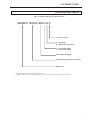


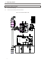

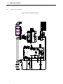
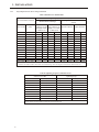

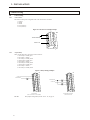
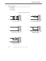
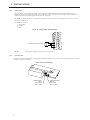
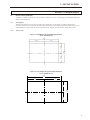
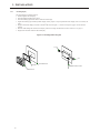

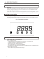
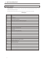
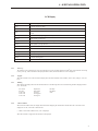

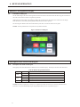

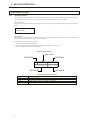
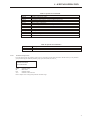
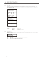
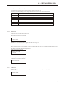

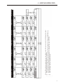


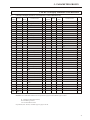

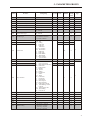
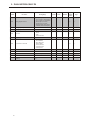
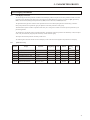
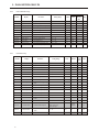


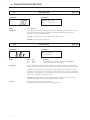
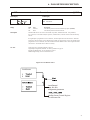

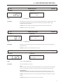


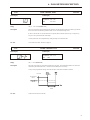

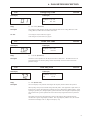
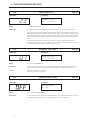
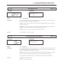
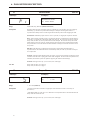
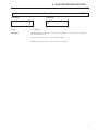

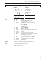
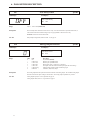
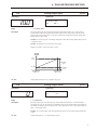


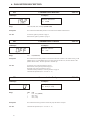
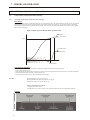
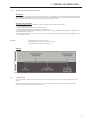

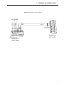


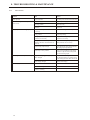

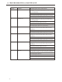
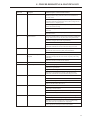
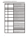

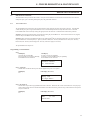


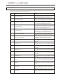


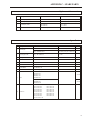

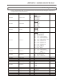
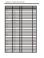

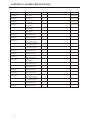


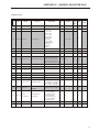


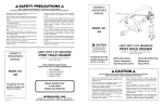


![EX MV MX3 User Manual [May16].vp](http://vs1.manualzilla.com/store/data/005646159_1-0d378a1c318c2dc00419aef6af60da73-150x150.png)