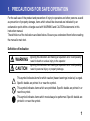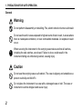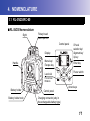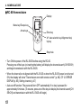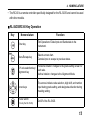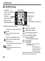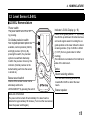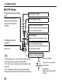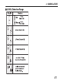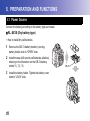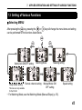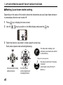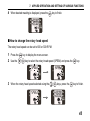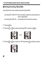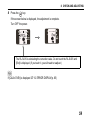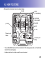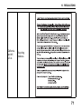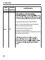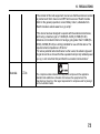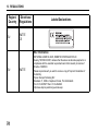
1
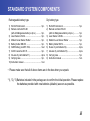
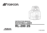
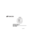
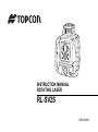
INSTRUCTION MANUAL ROTATING LASER RL-SV2S 31366 90032 FOREWORD Thank you for selecting the TOPCON instrument. • Please read this instruction manual carefully before using this instrument. • Verify that all equipment is included. C “ STANDARD SYSTEM COMPONENTS” (p. iii) • The specifications and general appearance of the instrument are subject to change without prior notice and without obligation by Topcon Corporation and may differ from those appearing in this manual. • Some of the diagrams shown in this manual may be simplified for easier understanding. i HOW TO READ THIS MANUAL XSymbols The following conventions are used in this manual. Indicates precautions and important items which should be read before : G operations. C : Indicates the chapter title to refer to for additional information. $ : Indicates supplementary explanation. ii STANDARD SYSTEM COMPONENTS Rechargeable battery type Dry battery type 1) RL-SV2S Instrument .......................................1pc. 2) Remote controller RC-60 (with AA Manganese battery x 2pcs.) .............1pc. 3) Level Sensor LS-80L.......................................1pc. 4) Model-6 Level Sensor Holder .........................1pc. 5) Battery holder DB-74C ....................................1pc. 6) Ni-MH battery pack BT-74Q ............................1set 7) AC/DC converter AD-15 ..................................1pc. 8) AA-size dry cell batteries*1) ............................4pcs. 9) Carrying case ..................................................1pc. 10) Instruction manual ...........................................1vol. 1) RL-SV2S Instrument....................................... 1pc. 2) Remote controller RC-60 (with AA Manganese battery x 2pcs.) ............ 1pc. 3) Level Sensor LS-80L ...................................... 1pc. 4) Model-6 Level Sensor Holder ........................ 1pc. 5) Battery holder DB-74 ...................................... 1pc. 6) D-size dry cell batteries*2).............................. 4pcs. 7) AA-size dry cell batteries*3)............................ 4pcs. 8) Carrying case ................................................. 1pc. 9) Instruction manual .......................................... 1vol. • Please make sure that all of above items are in the box when you unpack. *1), *2), *3)Batteries included in the package are to confirm the initial operation. Please replace the batteries provided with new batteries (alkaline) as soon as possible. iii CONTENTS FOREWORD ................................................................................................................................. I HOW TO READ THIS MANUAL................................................................................................... II STANDARD SYSTEM COMPONENTS ...................................................................................... III CONTENTS ................................................................................................................................. IV 1. PRECAUTIONS FOR SAFE OPERATION ............................................................................ 1 2. PRECAUTIONS ..................................................................................................................... 6 3. LASER SAFETY INFORMATION .......................................................................................... 8 Laser Safety................................................................................................................ 8 4. NOMENCLATURE ............................................................................................................... 11 4.1 RL-SV2S/RC-60 ........................................................................................................... 11 RL-SV2S Nomenclature............................................................................................ 11 RC-60 Nomenclature ................................................................................................ 12 RL-SV2S/RC-60 Key Operation................................................................................ 13 RL-SV2S/RC-60 Display ........................................................................................... 14 4.2 Level Sensor LS-80L .................................................................................................... 15 LS-80L Nomenclature ............................................................................................... 15 LS-80L Display.......................................................................................................... 16 LS-80L Detective Range........................................................................................... 17 5. PREPARATION AND FUNCTIONS ..................................................................................... 18 5.1 Power Source ............................................................................................................... 18 RL-SV2S (Dry battery type) ...................................................................................... 18 RL-SV2S (Rechargeable battery type) ..................................................................... 20 iv CONTENTS RC-60........................................................................................................................ 23 LS-80L....................................................................................................................... 23 5.2 How to set remote controller communication channel .................................................. 24 RL-SV2S ................................................................................................................... 24 RC-60........................................................................................................................ 24 6. BASIC OPERATION............................................................................................................. 25 6.1 Setting Up Instrument ................................................................................................... 25 Horizontal Rotation.................................................................................................... 25 Example Operational................................................................................................. 27 Vertical Rotation........................................................................................................ 27 6.2 Height Alert Function .................................................................................................... 28 How to reset .............................................................................................................. 28 7. APPLIED OPERATION AND SETTING OF VARIOUS FUNCTIONS.................................. 29 7.1 Setting Grades .............................................................................................................. 29 How to enter grade values ........................................................................................ 29 How to set grades ..................................................................................................... 31 Example of how to set up.......................................................................................... 33 Matching Mode (Manual Slope) ................................................................................ 35 7.2 Line Control (manual vertical beam alignment) ............................................................ 39 7.3 Setting of Various Functions ......................................................................................... 43 Selecting MENU........................................................................................................ 43 Masking (Laser beam shutter) setting....................................................................... 44 How to change the rotary head speed ...................................................................... 45 v CONTENTS 8. 9. 10. 11. 12. 13. vi Switching Auto leveling / Manual Mode .................................................................... 46 Setting channel ......................................................................................................... 47 Sleep mode............................................................................................................... 48 Height Alert ON/OFF................................................................................................. 49 CHECK AND ADJUSTING................................................................................................... 50 8.1 Check and Adjust Horizontal Rotation .......................................................................... 50 Horizontal Rotation Grade Error ............................................................................... 50 Horizontal Rotation Cone Error ................................................................................. 54 Grade Setting Error................................................................................................... 55 8.2 Vertical Calibration........................................................................................................ 57 Checking Calibration................................................................................................. 57 Vertical calibration and adjustment ........................................................................... 58 STORAGE PRECAUTIONS................................................................................................. 60 HOW TO STORE ................................................................................................................. 61 SPECIFICATIONS ............................................................................................................... 62 ERROR DISPLAY ................................................................................................................ 65 REGULATIONS.................................................................................................................... 68 1. PRECAUTIONS FOR SAFE OPERATION For the safe use of the product and prevention of injury to operators and other persons as well as prevention of property damage, items which should be observed are indicated by an exclamation point within a triangle used with WARNING and CAUTION statements in this instruction manual. The definitions of the indications are listed below. Be sure you understand them before reading the manual’s main text. Definition of Indication WARNING Ignoring this indication and making an operation error could possibly result in death or serious injury to the operator. CAUTION Ignoring this indication and making an operation error could possibly result in personal injury or property damage. This symbol indicates items for which caution (hazard warnings inclusive) is urged. Specific details are printed in or near the symbol. This symbol indicates items which are prohibited. Specific details are printed in or near the symbol. This symbol indicates items which must always be performed. Specific details are printed in or near the symbol. 1 1. PRECAUTIONS FOR SAFE OPERATION General Warning Do not perform disassembly or rebuilding. Fire, electric shock or burns could result. Do not use the unit in areas exposed to high amounts of dust or ash, in areas where there is inadequate ventilation, or near combustible materials. An explosion could occur. When securing the instrument in the carrying case make sure that all catches, including the side catches, are closed. Failure to do so could result in the instrument falling out while being carried, causing injury. Caution Do not use the carrying case as a footstool. The case is slippery and unstable so a person could slip and fall off it. Do not place the instrument in a case with a damaged case or belt. The case or instrument could be dropped and cause injury. 2 1. PRECAUTIONS FOR SAFE OPERATION Power Supply Warning Do not short circuit. Heat or ignition could result. Do not use voltage other than the specified power supply voltage. Fire or electrical shock could result. Do not use damaged power cords, plugs or loose outlets. Fire or electric shock could result. Do not use power cords other than those designated. Fire could result. Do not use batteries other than those designated. An explosion could occur, or abnormal heat generated, leading to fire. Do not place articles such as clothing on the battery charger while charging batteries. Sparks could be induced, leading to fire. Use only the specified battery charger to recharge batteries. Other chargers may be of different voltage rating or polarity, causing sparking which could lead to fire or burns. 3 1. PRECAUTIONS FOR SAFE OPERATION Do not heat or throw batteries into fire. An explosion could occur, resulting in injury. Do not use the battery or charger for any other equipment or purpose. Fire or burns caused by ignition could result. To prevent shorting of the battery in storage, apply insulating tape or equivalent to the terminals. Otherwise shorting could occur, resulting in fire or burns. Do not use batteries or the battery charger if wet. Resultant shorting could lead to fire or burns. Do not connect or disconnect power supply plugs with wet hands. Electric shock could result. Caution Do not touch liquid leaking from batteries. Harmful chemicals could cause burns or blisters. 4 1. PRECAUTIONS FOR SAFE OPERATION Tripod Caution When mounting the instrument to the tripod, tighten the centering screw securely. Failure to tighten the screw properly could result in the instrument falling off the tripod, causing injury. Tighten securely the leg fixing screws of the tripod on which the instrument is mounted. Failure to tighten the screws could result in the tripod collapsing, causing injury. Do not carry the tripod with the tripod shoes pointed at other persons. A person could be injured if struck by the tripod shoes. Keep hands and feet away from the tripod shoes when fixing the tripod in the ground. A hand or foot stab wound could result. Tighten the leg fixing screws securely before carrying the tripod. Failure to tighten the screws could lead to the tripod legs extending, causing injury. 5 2. PRECAUTIONS Before starting work or operation, be sure to check that the instrument is functioning correctly with normal performance. Vibration and Impact Protection When transporting the instrument, provide protection to minimize risk of severe vibration or impact. Severe vibration or impacts may affect beam accuracy. Sudden changes of temperature A sudden change in temperature may cause water condensation on the glass used for the laser emission part. In such a case, let the instrument stand for a while to allow it to adjust to the temperature prior to actual use. Exceptions from Responsibility • The user of this product is expected to follow all operating instructions and make periodic checks of the product’s performance. 6 2. PRECAUTIONS • The manufacturer, or its representatives, assumes no responsibility for results of a faulty or intentional usage or misuse including any direct, indirect, consequential damage, and loss of profits. • The manufacturer, or its representatives, assumes no responsibility for consequential damage, and loss of profits by any disaster, (an earthquake, storms, floods etc.). A fire, accident, or an act of a third party and/or a usage any other usual conditions. • The manufacturer, or its representatives, assumes no responsibility for any damage, and loss of profits due to a change of data, loss of data, an interruption of business etc., caused by using the product or an unusable product. • The manufacturer, or its representatives, assumes no responsibility for any damage, and loss of profits caused by usage except for explained in the user manual. • The manufacturer, or its representatives, assumes no responsibility for damage caused by wrong movement, or action due to connecting with other products. 7 3. LASER SAFETY INFORMATION The RL-SV2S is classified as a class 3R Laser Product according to IEC Standard Publication 60825-1 Ed.2.0: 2007 and United States Government Code of Federal Regulation FDA CDRH 21CFR Part1040.10 and 1040.11 (Complies with FDA performance standards for laser products except for deviations pursuant to Laser Notice No.50, dated June 24, 2007.) Laser Safety This product projects a visible laser beam during operation. This product is manufactured and sold in accordance with “Performance Standards for Light-Emitting Products” (FDA/BRH 21 CFR 1040) or “Radiation Safety of Laser Products, Equipment Classification, Requirements and User’s Guide” (IEC Publication 60825-1) provided on the safety standards for laser beam. As per the said standard, RL-SV2S standard model is classified as “Class 3R (IIIa) Laser Products”. These are simple products to operate and do not require training from a laser safety officer. In case of any failure, do not disassemble the instrument. Contact TOPCON or your TOPCON dealer. 8 3. LASER SAFETY INFORMATION Visible laser Laser output: 2.4mW Beam aperture Explanatory Label Each label is differed by the market. Warning Use of controls or adjustments or performance of procedures other than those specified herein may result in hazardous radiation exposure. Do not look directly into the laser beam. Doing so could cause permanent eye damage. 9 3. LASER SAFETY INFORMATION Do not stare at the laser beam. Doing so could cause permanent eye damage. If an eye injury is caused by exposure to the laser beam, seek immediate medical attention from a licensed ophthalmologist. Caution Perform checks at start of work and periodic checks and adjustments with the laser beam emitted under normal conditions. When the instrument is not being used, turn off the power. When disposing of the instrument, destroy the battery connector so that the laser beam cannot be emitted. Operate the instrument with due caution to avoid injuries that may be caused by the laser beam unintentionally striking a person in the eye. Avoid setting the instrument at heights at which the path of the laser beam may strike pedestrians or drivers at head height. 10 4. NOMENCLATURE 4.1 RL-SV2S/RC-60 RL-SV2S Nomenclature Sight Rotary head Beam aperture Control panel Handle Display X/Y axis selection key/ Alignment key/ Up key Menu key/ Escape key Enter key Level vial Power switch For Vertical Rotation Battery holder Battery holder knob Arrow keys Control panel Charging connector (only in the rechargeable battery type) 11 4. NOMENCLATURE RC-60 Nomenclature Display Menu key/Escape key Arrow keys Enter key X/Y axis selection key/Alignment key/ Up key Strap hole • Turn ON the power of the RL-SV2S before using the RC-60. Pressing one of the keys (or inserting the battery) will display the channel search (CH SErCH) and begin transmission with the RL-SV2S. • When the channel is not aligned with the RL-SV2S or when the RL-SV2S power is not turned ON, the display will show "Transmission error with remote control" (p. 66). C12. ERROR DISPLAY(p. 65), Setting channel (p. 47) • Auto-cut off function: The power will turn OFF automatically if no key is pressed for approximately 6 minutes. (To resume, press one of the keys to display the channel search [CH SErCH] and transmission with the RL-SV2S will begin.) 12 4. NOMENCLATURE • The RC-60 is a remote controller specifically designed for the RL-SV2S and cannot be used with other models. RL-SV2S/RC-60 Key Operation Key Nomenclature Function Enter key End Operation of Data Input and Sends data to the instrument. Menu/Escape key Selects a menu item. Cancels input or escape to previous status. X/Y axis selection key/ Alignment key Horizontal rotation: changes to the grade setting screen for each axis. Vertical rotation: changes to the Alignment Mode. Arrow keys The arrows indicate code selection, digit shift, and number input during grade setting, and designates direction during masking setting. Power switch (For only the RL-SV2S) On/Off of the RL-SV2S. 13 4. NOMENCLATURE RL-SV2S/RC-60 Display X axis grade Sample display (Flashes one digit at a time during auto leveling) Mask Mode display Y axis grade Rotation speed (Flashes one digit at a time during auto leveling) Manual Mode display Transmission and reception display Transmits to the receiving instrument (RC-60 or RL-SV2S) (Lights on until received by the receiving instrument) Receives from the transmitting instrument (Lights on until the transmitting instrument transmits next time) When transmission from the other instrument is not possible (Both marks will flash slowly until the next transmission) 6:600 rpm 3:300 rpm 5:500 rpm (Flashes when the battery is low) Battery remaining Ample power for operation Ample power for operation Power remaining for operation*1) Power remaining for operation Near power depletion*2) *1), *2) The laser speed will be 500 rpm. Power depletion Laser will stop Dry cell battery type: Replace with new batteries. Rechargeable battery type: When connecting to AD-15 during error display, turn OFF the power and then turn the power back ON to restore operation. (Battery power display for the RC-60 shows the remaining battery level on the RC-60 remote controller.) 14 4. NOMENCLATURE 4.2 Level Sensor LS-80L LS-80L Nomenclature Power switch The power switch turns ON or OFF by pressing. On-Grade precision switch Two on-grade precision options are available, normal precision (±2mm) and high precision (±1mm). By pressing this switch, the precision options are switched alternately. Confirm the precision choice by the indicator. (Normal precision is the default setting each time the sensor is turned on.) Buzzer sound switch Volume of the sensor buzzer can be alternately switched to LOW/LOUD/OFF by pressing the switch. Auto-cut off function Indicator LS-80L Display (p. 16) Detect the on-grade position "---" by moving the LS-80L up and down. Directional arrows and audio signals assist in locating the ongrade position as the laser strikes the beam receiving window. (Top of LS-80L is 40mm (1 9/16") from on-grade index for offset marking.) The indicators are located on front and back sides of the instrument. Index Beam receiving window Turn the beam receiving window side towards RL-SV2S to detect the laser beam. Buzzer speaker The power will be turned off automatically if no laser beam is detected for approximately 30 minutes. (To turn on the level sensor, press the power switch again.) 15 4. NOMENCLATURE LS-80L Display Height alert warning of rotating laser*1 A flash and a buzzer sound signifies that the height alert function of the RL-SV2S is operating. High precision mode Normal precision mode Higher than datum position (Buzzer sound:High frequent beep sound) Move the sensor downward. Datum position Rotating laser battery warning*2 (Buzzer sound:Continuous beep sound) Lower than datum position A flash shows that the RL-SV2S power is low. (Buzzer sound:Low frequent beep sound) Move the sensor upward. $ Battery remaining display The warning displays *1 and *2 are the functions that the LS-80L detects alarm signal from the RL-SV2S. The LS-80L can be canceled the alarm detection from the RL-SV2S. To be canceled the detection; Press the power switch while pressing the buzzer sound switch when powering on. 16 Battery is sufficient. The power is low, but laser is still usable. Dead battery. Replace the dry battery with new one. 4. NOMENCLATURE LS-80L Detective Range 17 5. PREPARATION AND FUNCTIONS 5.1 Power Source Connect the battery according to the battery type purchased. RL-SV2S (Dry battery type) • How to install dry cell batteries 1 Remove the DB-74 battery holder by turning battery holder knob to "OPEN" side. 2 Install the new 4xD size dry cell batteries (alkaline) referring to the illustration on the DB-74 battery holder.*1), *2), *3) 3 Install the battery holder. Tighten the battery cover knob to "LOCK" side. 18 DB-74 5. PREPARATION AND FUNCTIONS • How to remove dry cell batteries 1 Remove the DB-74 battery holder by turning battery holder knob to "OPEN" side. 2 Remove the dry cell batteries from the DB-74 battery holder. G *1 Replace all 4 batteries with new ones at the same time. Do not mix used and new batteries, and do not mix different types of batteries together. *2 Use alkaline dry cells. (Dry cells for movement confirmation are packed in shipment.) Nickel hydrogen dry cells and nickel cadmium dry cells can be used too, but the operating time is different from the time of alkaline dry cells. *3 Generally, performances of dry cell deteriorate temporarily in low temperature, but recover in normal temperature. • It is possible to remove the dry cell batteries from the DB-74 battery holder and use the battery pack BT-74Q. • The DB-74 dry cell battery holder cannot be used to charge the BT-74Q Ni-MH battery pack. Use the DB-74C charging battery holder instead. 19 5. PREPARATION AND FUNCTIONS RL-SV2S (Rechargeable battery type) • How to install the battery pack BT-74Q 1 Insert the battery pack BT-74Q into the DB-74C battery holder in the direction shown in the diagram on the right. 2 Install the battery holder. Tighten the battery cover knob to "LOCK" side. DB-74C • How to remove the battery pack 1 Remove the DB-74C battery holder by turning battery holder knob to "OPEN" side. • It is possible to remove the battery pack BT-74Q from the DB74C battery holder and use the dry cell batteries. Grasp the specified place on the battery holder, which is shown below, and remove the battery pack. 20 5. PREPARATION AND FUNCTIONS • For Charging Plug AD-15 1 Plug the AC/DC converter (AD-15) into the DB-74C battery holder or plug the AD-15 into the battery pack BT-74Q. 2 Insert the AD-15 power cord in an outlet. 3 Complete charging by unplugging the plug from the DB-74C battery holder or battery pack BT-74Q after approximately 13 hours. 4 Unplug the AD-15 power cord from the outlet. • RUN charge As illustrated at the right, while charging is in process with the power supply unit installed to the instrument, you can use the instrument. 21 5. PREPARATION AND FUNCTIONS G • Recharging should take place in a room with an ambient temperature range of 10°C to 40°C (50°F to 104°F). • Do not perform charging with others except the AC/DC converter AD-15. • For longer battery life, conform to the suggested charging time to the extent possible. • The battery source will discharge when stored and should be checked before using with instrument. • Do not recharge the battery when fully charged. Doing so will lower battery performance. • Be sure to charge stored battery source every 3 or 6 months and store in a place at 30 °C or below. If you allow the battery to become completely discharged, it will have an effect on future charging. 22 5. PREPARATION AND FUNCTIONS RC-60 • How to install dry cell batteries 1 Open the battery cover. 2 Remove the old batteries and replace with new 2xAA size dry cell batteries (alkaline) making sure each is placed in the proper direction as indicated. 3 Shut the battery cover until click sound can be heard. LS-80L • How to install dry cell batteries 1 Keep pushing the battery cover in 1 direction, and then try to slide the cover in 2 direction.The cover does not move but it will be open. 2 Remove the old batteries and replace with new 2xAA size dry cell batteries (alkaline) making sure each is placed in the proper direction as indicated. 3 Press the lid down and click to close. G • Replace all 2 batteries with new ones. • Do not mix old batteries and new ones. 23 5. PREPARATION AND FUNCTIONS 5.2 How to set remote controller communication channel The same channel (1 to 9) must be set on the RL-SV2S and the RC-60 remote controller. RL-SV2S CSetting channel (p. 47) RC-60 The setting method is the same as for the RL-SV2S. Use the RC-60 control panel for setting. CSetting channel (p. 47) When the channel is not aligned with the RL-SV2S, the display will show "Transmission error with remote control" (p. 66). 24 6. BASIC OPERATION 6.1 Setting Up Instrument Horizontal Rotation 1 Set the instrument to the tripod or smooth surface. 2 Press power switch (ON). Auto leveling will begin. After the auto leveling, the laser beam will emit horizontally. The RL-SV2S automatically levels within the range of ±5° as shown below. It is also possible to set grades for the RL-SV2S in the direction of 2 axes. C7.1 Setting Grades(p. 29) on how to set grades. ±5° 25 6. BASIC OPERATION 3 Press power switch on the LS-80L (ON). 4 Select the precision mode by pressing the On-Grade precision switch. C4.2 Level Sensor LS-80L(p. 15) 5 Locate the on-grade position “---” by moving the LS-80L up and down. 6 Mark the position of On-Grade index. (Top of the LS-80L is 40mm [1 9/16”] from index for offset marking.) 26 6. BASIC OPERATION Example Operational Install the LS-80L on a staff in the manner shown below. 154 153 152 151 150 Clamp knob 149 148 147 146 H O L D E R -6 131 9 138 137 136 135 134 Level sensor holder model 6 133 LS-80L 132 131 Vertical Rotation 1 Install the RL-SV2S on to the tripod and set so that the bubble is at the center of the vertical rotation circular level vial. 2 Press power switch . When auto leveling is complete, the laser beam will emit vertically. About manual line control C7.2 Line Control (manual vertical beam alignment)(p. 39) 27 6. BASIC OPERATION 6.2 Height Alert Function When the instrument system detects a shock, this Shock is given to the instrument. function informs the operator of it. Height Alert Display • When the instrument’s installation status (height) is sharply changed by the contact of the operator or the like, this function stops auto leveling to keep the operation accuracy and informs the operator of the situation. • After 10 minutes has passed since the auto (Flashing) leveling function was activated and the laser beam was emitted, this function works. • The height alert function will not operate while setting the dual axes grade in the Matching Mode, or Manual Mode. $ Height Alert ON/OFFCHeight Alert ON/OFF (p. 49) How to reset 1 Turn off the power switch. 2 Check whether the instrument is installed correctly. 3 Turn on the power switch. Auto leveling starts again. After auto leveling is finished, the laser beam is emitted. 4 Make sure that the laser beam is set at the correct height. Then, restart the operation. 28 7. APPLIED OPERATION AND SETTING OF VARIOUS FUNCTIONS It is possible to set grades for the laser beam and various functions from the menu screen. 7.1 Setting Grades There are two methods to set grades on the laser beam: 1) direct entry of the grade values for the X and Y axes, and 2) matching to set grades on laser beam according to the slope of the ground on site. How to enter grade values Grade can be set in both axes, X and Y, as shown below. Grades can be set in the range indicated below. Single axis Dual axes X axis Grade range: X: –15% to +15% or Y: –15% to +15% Y axis Grade range: X: –15% to +15% Y: –15% to +15% 29 7. APPLIED OPERATION AND SETTING OF VARIOUS FUNCTIONS Grade axes and axis symbols are as shown in the diagram below. Y axis +15% Minus Plus Plus Minus X axis Plus Minus -15% -15% Minus Plus +15% Panel side On the tripod whose head is horizontally placed, grades will automatically level to approximately ±8%. When setting larger grades, tilt the RL-SV2S towards the direction of the slope to maintain within the auto leveling range. When exceeding the auto leveling range, the error message "Exceeding leveling range" will be displayed.C12. ERROR DISPLAY(p. 65) G If you set grades by placing the RL-SV2S in a place where temperature suddenly changes, let the instrument stand for about 10 minutes to allow it to adjust to the temperature prior to actual use. When temperature changes 5°C or more after setting a grade, temperature difference is detected and the grade is corrected automatically. During auto correction, laser will stop temporarily (and [AUTO CALIb] will be displayed). When auto correction is completed, the display will return to the grade setting, and after auto leveling, laser will emit. 30 7. APPLIED OPERATION AND SETTING OF VARIOUS FUNCTIONS How to set grades 1 Press the key and the X axis display will start flashing. It is possible to enter the grade. (Pressing the key will toggle between the X axis and Y axis.) 2 Press the 3 Press the 1 Press the key and select the axis to reset the grade value. 2 Press both the keys simultaneously to reset the grade value. 3 Pressing the key will switch to the mark selection state. 4 Press the key. keys and select the mark (plus or minus). 4 Press the Resetting the grade value keys to change the digit position. key again to set 0 %. 31 7. APPLIED OPERATION AND SETTING OF VARIOUS FUNCTIONS 5 Press the 6 Press the keys to increase or decrease the value of the digit. key to confirm the value. 7 When setting the grade for the Y axis, press the key. The Y axis display will start flashing. Set up the grade in the same manner as the X axis. $ • To set with the RC-60, check the transmission and reception display. 32 7. APPLIED OPERATION AND SETTING OF VARIOUS FUNCTIONS Example of how to set up When setting grade, it is necessary to accurately set the RL-SV2S to the direction of grade setting. Below is an example of how to set grades to the accurate grade setting direction. (To work at Y-3% grade surface to the base line) LS-80L base line Grade to work 33 7. APPLIED OPERATION AND SETTING OF VARIOUS FUNCTIONS 1 Set up the RL-SV2S on Point A of the base line using the plumb bob on the tripod. 2 Using the sight at the upper section of the RL-SV2S, adjust the direction on top of the tripod and roughly align the X+ direction to Point B on the standard axis. 3 Horizontally rotate the laser beam of the RL-SV2S. (X+0.000%, Y+0.000%) 4 At Point B adjust the height of the LS-80L installed on a pole, align the standard position of the LS-80L with the laser beam and fix. 5 Set the RL-SV2S at X+0.000% and Y-3.000% grades. 6 Align the RL-SV2S direction on top of the tripod so as to have the laser beam in the ongrade position of the LS-80L in step 4. G Do not change the height of the LS-80L installed on the pole. If the height of the RL-SV2S is changed, return to step 3 and redo the adjustment. 34 7. APPLIED OPERATION AND SETTING OF VARIOUS FUNCTIONS Matching Mode (Manual Slope) This mode is used to align the grades of the laser calibration to the worked grade. 1 Horizontally rotate the laser beam of the RL-SV2S set up at the standard height. (X+0.000%, Y+0.000%) LS-80L 2 Adjust the height of the LS-80L installed on the pole and align the standard position of the LS-80L with the laser beam and fix. 3 Set up the LS-80L in step 2 on the grade surface. 4 Using the sight, roughly align and set the position of the RL-SV2S on top of the tripod to the direction of the LS-80L. 5 Press the 6 Press the key. key on the Matching Mode (SLOPE) selection screen. 35 7. APPLIED OPERATION AND SETTING OF VARIOUS FUNCTIONS 7 Confirm that auto leveling is complete and that the laser beam is emitting. Press the arrow key ( :To align with grade on the X- side) once in the desired direction to align grades, and the laser beam will continue to lean toward the direction of the key. The arrow key cannot be used until auto leveling is complete and the laser beam starts emitting. 8 Pressing either of key for the graded axis pressed in step 7 once again will stop laser beam grading. If neither of arrow keys is pressed once more, the laser beam will return to the horizontal position. 9 Press key to adjust the grade of the laser beam and 36 Grading direction of the laser beam during arrow key operation Key Display* Grading direction of the laser beam XX- X+ X+ YY- Y+ Y+ 7. APPLIED OPERATION AND SETTING OF VARIOUS FUNCTIONS align with the standard position for the LS-80L. The length of time the arrow key is pressed will change the speed at which the laser beam grades. (The speed will change from low to high speed.) For Y-axis grading, follow steps 7 to 9 using keys. * Display during arrow key operation The laser beam is moving in the X (Y) + direction. The laser beam is moving in the X (Y) - direction. $ • When the , , , or key is pressed, the laser beam will emit even if auto leveling starts. • This mode can be used with the RC-60. • When the RC-60 is used in an environment in which similar radio signals (wireless LAN, etc.) are transmitted, and when the , , , or key is long-pushed in step 9, the laser beam grading may stop. If this interferes with the operation, change the communication channel for the RL-SV2S and RC-60 and try again. C5.2 How to set remote controller communication channel(p. 24) 37 7. APPLIED OPERATION AND SETTING OF VARIOUS FUNCTIONS [Display during the Matching Mode] is flashing SLOPE LEVEL : in the Matching Mode. It is possible to adjust the grade of the laser beam with arrow keys. When a certain amount of time has passed after the arrow key operation, the light that was flashing will remain lit. Grading cannot be adjusted when is on. : shows the axis on which the grading is being adjusted. : shows the axis that is being graded. Auto leveling of the axis will not function at this time. : shows the axis whose grade is being automatically leveled horizontally. A flashing display indicates that auto leveling is being performed. The height alert function setting is valid at this time. To readjust grading, return to step 5 and follow directions thereafter. However, skip steps 7 and 8 for an axis that is already graded. Exiting the Matching Mode When When is flashing : press the key to exit the Matching Mode. Press the grade value. is lighted : press the key to set the grade value. CHow to set grades (p. 31) 38 key to set 7. APPLIED OPERATION AND SETTING OF VARIOUS FUNCTIONS 7.2 Line Control (manual vertical beam alignment) The laser beam can be moved to the direction of the key during vertical rotation. $ • Only the X axis can be moved. • Allowable alignment range: ±5° (when the instrument is set up on the 0° surface) 1 Set the instrument. 2 Press the Power control key to turn unit on. When LS-80L autoleveling is complete, the laser beam will be rotate vertically. 3 Move and set the RL-SV2S to align reference point key A and the laser beam. key $ Make sure that the RL-SV2S is set so that the bubble is at the center of the vertical rotation circular level vial on If it is unable to visually confirm the laser the control panel. beam on reference point A and B, set up the LS-80L on either of the Points. 39 7. APPLIED OPERATION AND SETTING OF VARIOUS FUNCTIONS 4 Press the key to enter the Line Control Mode. is flashing :in the Line Control Mode. It is possible to adjust the laser beam with key. When a certain amount of time has passed after the key operation, the light that was flashing will remain lit. The laser beam cannot be adjusted when the light is on. LEVEL is flashing :performing auto leveling in the vertical direction. 5 Confirm that auto leveling is complete and that the laser beam is emitting. Press either of key once and the laser beam will move in the direction of the key to begin search. The emitting. key cannot be used until auto leveling is complete and the laser beam starts 6 Pressing either of beam. If neither of 7 Press either one of the key pressed in step 6 again will stop the movement of the laser key is pressed, the laser beam will return to the central area. key to move the beam right or left until it is precisely aligned to reference point B. The speed of laser beam movement will change according to the duration of time the key is being pressed. (The speed will change from low to high speed.) 40 7. APPLIED OPERATION AND SETTING OF VARIOUS FUNCTIONS Direction of laser beam movement when operating Key Display* key Direction of laser beam movement XX- X+ X+ C * Display during arrow key operation (p. 37) When readjusting with line control, return to step 4 and follow directions thereafter. In such a case, however, skip steps 5 and 6. $ • During the vertical rotation or the manual line control, the laser beam will emit even if auto leveling starts. 41 7. APPLIED OPERATION AND SETTING OF VARIOUS FUNCTIONS • This mode can be used with the Remote Controller RC-60. • When the RC-60 is used in an environment in which similar radio signals (wireless LAN, etc.) are transmitted, and when the or key is long-pushed in step 7, the laser beam grading may stop. If this interferes with the operation, change the transmission channels for the RL-SV2S and the RC-60 and try again. C5.2 How to set remote controller communication channel(p. 24) 42 7. APPLIED OPERATION AND SETTING OF VARIOUS FUNCTIONS 7.3 Setting of Various Functions Selecting MENU After pressing the key, pressing the or can be performed for the functions listed below. Safety lock ON/OFF setting Sleep Mode setting This menu is only available for the RC-60. key will change the menu items and setting Matching Mode Remote channel setting Masking setting Manual Mode ON/ OFF setting Speed setting • For Matching Mode, see the Matching Mode (Manual Slope) (p. 35). 43 7. APPLIED OPERATION AND SETTING OF VARIOUS FUNCTIONS Masking (Laser beam shutter) setting Depending on the status of the location where the instruments are used, laser beam emission to unnecessary direction can be shut off. 1 Press 2 Use the key to display the menu screen. key to position on the Mask display and press the key. 3 Select the direction you desire to mask using the arrow keys. Each press repeats mask activating/releasing. The state when masking is not activated. (Laser beams are emitted to all directions.) Displays the masking direction Arrow keys and masking setting directions 44 RL-SV2S upper surface diagram and masking directions The status in which the Y+ direction is masked. (Laser beam is shut off in the Y+ direction.) 7. APPLIED OPERATION AND SETTING OF VARIOUS FUNCTIONS 4 When desired masking is displayed, press the key to finish. How to change the rotary head speed The rotary head speed can be set to 600 or 300 R.P.M. 1 Press the 2 Use the key to display the menu screen. key to select the rotary head speed (SPEEd) and press the 3 When the rotary head speed selected using the keys, press the key. key to finish. 45 7. APPLIED OPERATION AND SETTING OF VARIOUS FUNCTIONS Switching Auto leveling / Manual Mode Auto leveling function can be canceled and switched to Manual Mode. Auto leveling OFF (LEVEL OFF): After auto leveling is complete, the auto leveling function will stop. (Manual Mode) Auto leveling ON (LEVEL ON): Auto leveling function will be effective at all times. 1 Press the 2 Press the key. or key to select auto leveling (LEVEL), and press the 3 Press the or key to select ON or OFF and press the 46 key. key. Setting is complete. 7. APPLIED OPERATION AND SETTING OF VARIOUS FUNCTIONS Setting channel When more than one RL-SV2Ss is used at the same location, change the communication channel to prevent interference. $ You may set the channel from 1 to 9. 1 Press the key to display the menu screen. 2 Press the or press the 3 Press the key to select the communication channel (CH.SET) setting, and key. or key to select the channel and press the To shift to other modes, press the key. Setting is complete. key. 47 7. APPLIED OPERATION AND SETTING OF VARIOUS FUNCTIONS Sleep mode When the Sleep Mode is turned ON with the RC-60, the RL-SV2S will change to the Standby Mode (Laser OFF, head rotation OFF and auto leveling OFF). 1 Press the 2 Press the key. 3 Press the key. Setting is complete. or key and select Sleep Mode (SLEEP), and press the key. $ There are two ways to revert from the Sleep Mode. • Press one of the keys on RC-60. • Turn OFF the power using the power key for the RL-SV2S, and turn the power back on. After reverting from the Sleep Mode, the former status is kept in the selected mode except Matching Mode and Manual Mode. 48 7. APPLIED OPERATION AND SETTING OF VARIOUS FUNCTIONS Height Alert ON/OFF C6.2 Height Alert Function(p. 28) 1 Press the 2 Press the key. or key and select Safety Lock ON/OFF (Hl.ALr), and press the 3 Press the or key and select ON or OFF, and press the key. key. Setting is complete. To shift to other modes, press the key. 49 8. CHECK AND ADJUSTING Please perform check and adjusting regularly. First check, and then make adjustments accordingly. 8.1 Check and Adjust Horizontal Rotation Horizontal Rotation Grade Error Y+ • How to check X+ X- 1 Set up tripod approximately 50 meters away from a wall, and set the instrument on level with the X1 facing the wall. 2 While pressing the key, turn ON the power. (Only the RL-SV2S is operable). [CaLIb] will flash on the X axis screen. *1) Handle Control Panel YLS-80L X- laser beam X- laser position 3 Press the key. (Hereafter, the RL-SV2S and RC-60 become operable.) 50 Staff or Wall 50m (164feet) 8. CHECK AND ADJUSTING The screen will be in the X-axis check and adjusting mode. Auto leveling on the RL-SV2S is complete and the laser will emit. 4 Turn the LS-80L to the high precision mode. 5 Detect the center of the laser beam on the wall with the LS-80L and mark it. (X1) 6 Press the key. 7 Loosen the centering screw and rotate the RL-SV2S 180°, and tighten the screw to secure. The RL-SV2S X+ surface will face the wall. When rotating the RL-SV2S, ensure that the instrument height is not misaligned. The RL-SV2S auto leveling is complete and the laser will emit. 51 8. CHECK AND ADJUSTING 8 Detect the center of the LS-80L laser beam on the wall and mark (X2). X1 9 If the difference in height of the two laser beam marks (X1 and X2) is less than 5 mm, no adjustment is required. Turn OFF the power. If the difference is more than 5 mm, follow adjusting steps for horizontal rotation. CHow to adjust (p. 53) X2 X2 laser beam 50m X2 laser position 10 Perform check on the Y axis after the adjustment for the X axis is complete. *1) When checking and adjusting the Y axis direction, press the Press the key. The screen will switch to the Y axis check and adjusting mode. key. G A difference between X1 and X2 is more than 40 mm (±90"), it is outside of the adjustment range. Contact your dealer or Topcon. 52 8. CHECK AND ADJUSTING • How to adjust 1 According to step 9 of the horizontal rotation check, press the keys* to move the laser beam between X1 and X2. * When adjusting the Y axis direction, press the OR 2 Press the keys. C * Display during arrow key operation (p. 37) key. Adjustment for X axis is complete. Turn OFF the power. Exceeding the range of adjustment. C12. ERROR DISPLAY(p. 65) The RL-SV2S is calculating the correction value. Do not touch the RL-SV2S until [End] is displayed. (If you touch it, you will need to readjust.) 53 8. CHECK AND ADJUSTING Horizontal Rotation Cone Error Perform the following check after completing “Horizontal Rotation Grade Error” on the previous page. Approx.50m Cone Error Wall A Standard location Wall B Wall A Wall B 1 Set up the laser centered between two walls approximately 50 m (164 ft) apart. Orient the instrument so one axis, either X or Y, is facing the walls. Grade should be set to 0% in both axes. 2 Locate and mark the position of the RL-SV2S beam on both walls using the LS-80L. 3 Turn off the RL-SV2S and move the RL-SV2S closer to wall A (1 m to 2 m /3 ft to 6 ft). Do not change the axis orientation of the RL-SV2S. Turn the RL-SV2S on. 4 Again locate and mark the position of the RL-SV2S beam on both walls using the LS-80L. 5 Measure the distance between the first and second marks on each wall. 54 8. CHECK AND ADJUSTING 6 If the difference between each set of marks is less than ±5 mm (±7/32 of an inch), no error exists. G If the difference between [wall A]-side and [wall B]-side exceeds ±5 mm (±7/32 of an inch), contact your dealer or Topcon. Grade Setting Error Perform the following check only after completing “Horizontal Rotation Grade Error” and “Horizontal Rotation Cone Error”. • Checking 1 Setup the X- side facing the staff as shown in the figure. LS-80L Staff Nail 1 Nail 2 Securely position Nail 1 and Nail 2 exactly 30m apart. 55 8. CHECK AND ADJUSTING 2 Turn on power for the RL-SV2S and verify the staff height of Nail 1 and Nail 2 at grade setting of 0% with LS-80L and record. At this time the staff height for Nail 1 and Nail 2 should recorded as h1 and h2 (mm). Check the LS-80L is set at high precision. 3 Set X axis grade to +1.000%. Align read the elevation of the laser beam in millimeters at Nail 1 and Nail 2. Designate these elevations as “h3” at Nail 1, and “h4” at Nail 2. 4 Using the elevation readings for h1, h2, h3 and h4, complete the equation below. If the calculated result is the range of 0.990% - 1.010%, the instrument is normal. If the calculated result for either axis is out of the range, contact your dealer or Topcon. Repeat the procedure aligning the “Y” axis on the line created by Nail 1 and Nail 2. 56 8. CHECK AND ADJUSTING 8.2 Vertical Calibration Checking Calibration Beam 1 Turn ON the power for the LS-80L and move into high precision mode. 2 Install the LS-80L on a beam 10 meters or Level sensor higher above the floor, as shown in the diagram. 3 Hang the plumb bob from the LS-80L indicator to the floor (Point A). 4 Mark the standard line on the floor perpendicular to Approx.10m the direction of the beam where Point A crosses. 5 Set up the RL-SV2S for vertical rotation at the position shown in the diagram and turn ON the power. Standard line 6 Maintain the level of the standard line on the floor and laser beam, and move the RL-SV2S to the direction of the arrow. Laser beam Ensure that the laser beam is at the LS-80L indicator position (check with the buzzer sound from the LS-80L). Approx.10cm 57 8. CHECK AND ADJUSTING 7 Measure the difference X between the standard line and laser beam. 8 If X is within 1 mm, no adjustment is required. If the difference exceeds 1 mm, move on to the next adjustment. Vertical calibration and adjustment 1 While pressing the Press the key, press the key. key. 2 Move the RL-SV2S in the direction of the arrow to align the standard line and laser beam. 3 Press either the key or the key to align the laser beam with the LS-80L indicator position. (check with the buzzer sound from the LS-80L) 58 8. CHECK AND ADJUSTING 4 Press the key. If the screen below is displayed, the adjustment is complete. Turn OFF the power. The RL-SV2S is calculating the correction value. Do not touch the RL-SV2S until [End] is displayed. (If you touch it, you will need to readjust.) $ If [CALIb OVEr] is displayed C12. ERROR DISPLAY(p. 65) 59 9. STORAGE PRECAUTIONS Always clean the instrument after use. • If the instrument got wet with rain, wipe it well before storing in the storage case. • Wipe away stain or dirt with soft cloth after dusting. • Clean storage case using cloth moistened with neutral detergent or water. Do not use ether, benzene, thinner or other solvents. • Clean the lens by first removing dust with a cleaning brush and then lightly wiping with the cleaning cloth included in the package or with a clean non-sticky or non-oily cloth (washed cotton cloth is the best) moistened with alcohol (or ether-mixed liquid). 60 10. HOW TO STORE After using the instrument, store it as shown below. RC-60 LS-80L (LS-80A/80B/90) Level sensor holder model 6 (LS-B10) RL-SV2S AD-15 BT-74Q D size dry cell battery AA size dry cell battery • The LS-80A/80B/90 and LS-B10 can be stored in this carrying case (The LS-70 cannot be stored in this carrying case). • Holders other than the holder model 6 cannot be stored. 61 11. SPECIFICATIONS RL-SV2S Light source Laser output Safety standard for laser beam Automatic correction range : : : : Grade setting range Accuracy : : Manual slope settable range : Line control during vertical rotation: Rotation speeds : Operating range : Power supply/Operating time : 62 Laser diode (Visible, 635nm) 2.4mW CDRH (FDA) Class IIIa, IEC Class 3R Horizontal ±5° Vertical ±5° X:±15% Y:±15% Horizontal ±10" Vertical ±10" ±5° (When the instrument is installed on the 0°surface) The slope range is increased or decreased according to the tilt of the surface on which the instrument is installed. ±5° (When the instrument is installed on the 0°surface) 300/600rpm (Changeable) Diameter Approx. 2m to 800m (rotation speed 600 r.p.m/Using with LS-80L) 4 x D size dry cell batteries (alkaline) or Ni-MH battery pack BT-74Q (7000mAh) Charging time : Approx. 13 hours (Using with AD-15) Operating time : Approx. 120 hours(Using with alkaline manganese dry battery / at +20° C (+68° F)) Approx. 65 hours (Using with Ni-MH battery pack BT-74Q/ at +20° C (+68° F)) 11. SPECIFICATIONS Protection against water and dust : Operating temperature : Storable temperature range : LS warning display : Dimensions Laser beam height : : Weight : Tripod screw : IP66 (Based on the standard IEC60529) –20 °C to +50 °C (–4 °F to +122 °F) –30 °C to +60 °C (–22 °F to +140 °F) RL-SV2S height alert warning (Warning is displayed on the indicator of LS-80L.) RL-SV2S battery warning (Warning is displayed on the indicator of LS-80L.) 177 (L) × 196 (W) × 217 (H) mm [7.0 (L) × 7.7 (W) × 8.5 (H) in] 187mm (Height from the instrument’s bottom surface to the center point of laser beam) 2.5kg (lbs) (Dry battery type: Including dry batteries) 2.7kg (lbs) (Ni-MH battery type: Including BT-74Q) 5"/8X11 threads for surveying instrument RC-60 Operating range (Radius) : Power source : Continuous operating time(+20°C): Protection against water and dust : Operating temperature : Storable temperature range : Dimensions : Weight : 100m or more 2×AA size dry cell batteries Approx. 3.5 months (depends on the nature of use) IP66 (Based on the standard IEC60529) –20 °C to +50 °C (–4 °F to +122 °F) –30 °C to +60 °C (–22 °F to +140 °F) 116 (L) × 59 (W) × 31.4 (H) mm [4.6 (L) × 2.3 (W) × 1.2 (H) in] 0.2kg (0.4lbs) (Including dry cell batteries) 63 11. SPECIFICATIONS LS-80L (Back side display area) Beam detection window : Beam detection precision High precision : Normal precision : Beam detection indication : Power source : Operating time : Auto shut-off delay : Protection against water and dust : Operating temperature : Storage temperature : Dimensions : Weight : 64 50 mm (2.0 in) ±1 mm (±0.04 in) ±2 mm (±0.08 in) Liquid crystal (both sides) and buzzer 2×AA size dry cell batteries Approx. 120 hours (Using alkaline manganese dry cell batteries) Approx. 30 minutes without beamdetection IP66 (Based on the standard IEC60529) -20°C to +50°C (-4°F to +122°F) -30°C to +60°C (-22°F to +140°F) 146(L) x 76(W) x 26(H)mm (5.7 x 2.9 x 1.0 in) 0.19 kg [0.41 lbs] (including dry cell batteries) 12. ERROR DISPLAY If an error is displayed, follow the procedures shown below. Error Display Description/Countermeasure The Height Alert Function is working. C6.2 Height Alert Function(p. 28) RL-SV2S setting exceeds the leveling range. Reset tilting to the direction to raise the X+ side. Reset tilting to the direction to raise the X- side. Alternate flashing Reset tilting to the direction to raise the Y+ side. OR Reset tilting to the direction to raise the Y- side. 65 12. ERROR DISPLAY Error Display Description/Countermeasure Transmission error with remote control. Change both the RL-SV2S and RC-60 to other channel. If the error persists, check the transmission environment and reduce wireless LAN and other similar wireless transmissions as much as possible. More than 2 RL-SV2S devices are within the transmission range of the RC-60, making transmission impossible. Change the channel for both the RL-SV2S (1) and RC-60 used for the operation to another channel. Exceeding the adjustment range. Turn the power of the RL-SV2S OFF, turn ON the power back again and readjust. This is an error with the RL-SV2S. Check the RL-SV2S display. 66 12. ERROR DISPLAY Error Display E-05 E-51,55 Description/Countermeasure Turn the power for the instrument off, and then turn it back on. Internal error for the RC-60 Transmission not possible with the RL-SV2S. Remove and replace the dry cell batteries from the RC-60. Wireless function error for the RL-SV2S. Unable to transmit with the RC-60. Turn the power for the instrument off, and then turn it back on. E-56 E-65 Internal transmission error for the RL-SV2S. Turn the power for the instrument off, and then turn it back on. E-70’s Slope function error. Turn the power for the instrument off, and then turn it back on. E-80’s Leveling incomplete. Turn the power for the instrument off, and then turn it back on. E-99 Internal memory error for the RL-SV2S. Turn the power for the instrument off, and then turn it back on. • If errors still persist after attempting to clear them, contact Topcon or your dealer. 67 13. REGULATIONS Region/ Country Directives/ Regulations Labels/Declarations FCC Compliance This device complies with Part 15 of the FCC Rules. Operation is subject to the following two conditions: (1) This device may not cause harmful interference, and (2) this device must accept any interference received, including interference that may cause undesired operation. FCC ID: H5P-RLSV(RL-SV2S) /Contains FCC ID: H5P-RF10(RC-60) NOTE: U.S.A. 68 FCC This equipment has been tested and found to comply with the limits for a Class A digital device, pursuant to part 15 of the FCC Rules. These limits are designed to provide reasonable protection against harmful interference when the equipment is operated in a commercial environment. This equipment generates, uses, and can radiate radio frequency energy and, if not installed and used in accordance with the instruction manual, may cause harmful interference to radio communications. Operation of this equipment in a residential area is likely to cause harmful interference in which case the user will be required to correct the interference at his own expense. This equipment should be installed and operated with at least 20cm and more between the radiator and person’s body (excluding extremities: hands, wrists, feet and ankles). 13. REGULATIONS WARNING: Change or modifications not expressly approved by the party responsible for compliance could void the user's authority to operate the equipment. Specified cables must be used for connection to computer and/or peripherals in order to meet FCC emission limits. CAUTION: This device and its antenna(s) must not be co-located or operating in conjunction with any other antenna or transmitter. End user cannot modify this transmitter device. Any unauthorized modification made on the device could avoid the user's authority to operate this device. Declaration of Conformity Model Number:RL-SV2S/RC-60 Trade Name:TOPCON CORPORATION Manufacture Name: TOPCON CORPORATION Address: 75-1, Hasunuma-cho, Itabashi-ku, Tokyo, 174-8580 JAPAN Country: JAPAN U.S.A. Representative Responsible party:TOPCON POSITIONING SYSTEMS,INC. Address: 7400 National Drive Livermore, CA94551, U.S.A Telephone number:925-245-8300 69 13. REGULATIONS Region/ Country California, U.S.A. 70 Directives/ Regulations Proposition65 Labels/Declarations 13. REGULATIONS California, and NY, U.S.A. Recycling Batteries 71 13. REGULATIONS Region/ Country Directives/ Regulations Labels/Declarations IC: 6050A-RLSV (RL-SV2S) /Contains IC: 6050A-RF10(RC-60) The term “IC:” before the radio certification number only signifies that Industry Canada technical specifications were met. Canada 72 ICES “Operation is subject to the following two conditions: (1) this device may not cause interference, and (2) this device must accept any interference, including interference that may cause undesired operation of the device.” 13. REGULATIONS “The installer of this radio equipment must ensure that the antenna is located or pointed such that it does not emit RF field in excess of Health Canada limits for the general population; consult Safety Code 6, obtainable from Health Canada’s website www.hc-sc.gc.ca/rpb” “This device has been designed to operate with the antennas listed below, and having a maximum gain of 1.84dBi (RL-SV2S), 0.95dBi (RC-60). Antennas not included in this list or having a gain greater than 1.84dBi (RLSV2S), 0.95dBi (RC-60) are strictly prohibited for use with this device. The required antenna impedance is 50 ohms.” “To reduce potential radio interference to other users, the antenna type and its gain should be so chosen that the equivalent isotropic ally radiated power (e.i.r.p.) is not more than that permitted for successful communication.” Australia C-Tick The compliance label indicates that the product complies with the applicable standard and establishes a traceable link between the equipment and the manufacturer, importer or their agent responsible for compliance and for placing it on the Australian market. 73 13. REGULATIONS Region/ Country EU Directives/ Regulations Labels/Declarations R&TTE CE R&TTE Directive EU 74 R&TTE ROTATING LASER RL-SV2S, REMOTE CONTROLLER RC-60 Hereby, TOPCON CORP., declares that the above-mentioned equipment is in compliance with the essential requirements and other relevant provisions of Directive 1999/5/EC. Please inquire below if you wish to receive a copy of Topcon's Declaration of Conformity. Topcon Europe Positioning B.V. Essebaan 11, 2908 LJ Capelle a/d IJssel, The Netherlands Tel:+31-10-4585077 Fax:+31-10-2844949 http://www.topcon-positioning.eu/index.asp 13. REGULATIONS Region/ Country Directives/ Regulations EU WEEE Directive EU EU Battery Directive Labels/Declarations 75 This is the mark of the Japan Surveying Instruments Manufacturers Association. ©2011 TOPCON CORPORATION ALL RIGHTS RESERVED http://www.topcon.co.jp Please see the attached address list or the following website for contact addresses. GLOBAL GATEWAY http://global.topcon.com/