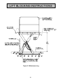
1
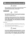
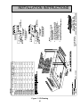
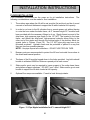
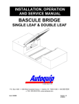
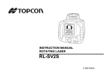
INSTALLATION, OPERATION AND SERVICE MANUAL PLT SCISSORS DOCK LIFT P.O. Box 1058 • 1058 West Industrial Avenue • Guthrie, OK 73044-1058 • 405-282-5200 • FAX: 405-282-8105 • www.autoquip.com Item # 830PLT Version 3.0 12/2004 TABLE OF CONTENTS Identification and Inspection 3 Responsibility of Owners/Users 4 Safety Signal Words 5 Safety Practices 6 Label Identification 10 Specifications 14 Lift Blocking Instructions 16 Installation Instructions 19 Operating Instructions 33 Routine Maintenance 34 General Maintenance 36 Replacement Parts List 51 Troubleshooting Analysis 57 IMPORTANT Please read and understand this manual prior to installation or operation of this lift. Failure to do so could lead to property damage and/or serious personal injury. If questions arise, call a local representative or Autoquip Corporation at 1-888-811-9876 or 405-282-5200. PLANNED MAINTENANCE PROGRAM A local Autoquip representative provides a Planned Maintenance Program (PMP) for this equipment using factory-trained personnel. Call a local representative or Autoquip Corporation at 1-888-811-9876 or 405-282-5200 for more information. 2 IDENTIFICATION & INSPECTION IDENTIFICATION When ordering parts or requesting information or service on this lift, PLEASE REFER TO THE MODEL AND SERIAL NUMBER. This information is on a nameplate attached to the leg assembly. Replacement parts are available from a local Autoquip distributor. INSPECTION Immediately upon receipt of the lift, a visual inspection should be made to determine that the lift has not been damaged in transit. Any damage found must be noted on the delivery receipt. In addition to this preliminary inspection, the lift should be carefully inspected for concealed damage. Any concealed damage found that was not noted on the delivery receipt should be reported in writing to the delivering carrier within 48 hours. The following is a checklist that will aid in the inspection of the lift. 1. Examine entire unit for any signs of mishandling. Pay special attention to the power unit and controls. 2. Thoroughly examine all connections, making sure they have not vibrated loose during transit. 3. After installation, raise the lift and inspect the base frame and scissors assembly. 3 RESPONSIBILTY OF OWNERS/USERS DEFLECTION It is the responsibility of the user/purchaser to advise the manufacturer where deflection may be critical to the application. INSPECTION & MAINTENANCE The lift shall be inspected & maintained in proper working order in accordance with Autoquip’s operating/maintenance (O&M) manual and with other applicable safe operating practices. REMOVAL FROM SERVICE Any lift not in safe operating condition such as, but not limited to, excessive leakage, missing rollers, pins, or fasteners, any bent or cracked structural members, cut or frayed electric, hydraulic, or pneumatic lines, damaged or malfunctioning controls or safety devices, or any other indication of excessive wear or worn parts shall be removed from service until it is repaired to the original manufacturer’s standards. REPAIRS All repairs shall be made by qualified personnel in conformance with Autoquip’s instructions, and be made using only authorized, Autoquip parts. OPERATORS Only trained personnel and authorized personnel shall be permitted to operate the lift. BEFORE OPERATION Before using the lift, the operator shall have: • Read and/or had explained, and understood, the manufacturer’s operating instructions and safety rules. • Inspected the lift for proper operation and condition. Any suspect item shall be carefully examined and a determination made by a qualified person as to whether it constitutes a hazard. All items not in conformance with Autoquip’s specification shall be corrected before further use of the lift. DURING OPERATION The lift shall only be used in accordance with Autoquip’s O&M manual. • Do not overload the lift. • Ensure that all safety devices are operational and in place. MODIFICATIONS OR ALTERATIONS Modifications or alterations to industrial lifting equipment shall be made only with expressed, written permission of Autoquip. Unauthorized modifications or parts replacements with unauthorized or non-specified parts could affect adversely affect the performance, code compliance, or safety of the equipment and are grounds for voiding all warranties. 4 SAFETY SIGNAL WORDS SAFETY ALERTS (Required Reading!) The following SAFETY ALERTS are intended to create awareness of owners, operators, and maintenance personnel of the potential safety hazards and the steps that must be taken to avoid accidents. These same alerts are inserted throughout this manual to identify specific hazards that may endanger uninformed personnel. Identification of every conceivable hazardous situation is impossible. Therefore, all personnel have the responsibility to diligently exercise safe practices whenever exposed to this equipment. ____________________________________________________________ DANGER! Identifies a hazardous situation which, if not avoided, will result in death or severe personal injury. _____________________________________________________________ WARNING! Identifies a hazardous situation which, if not avoided, could result in death or serious personal injury. CAUTION! Identifies a hazardous situation which, if not avoided, may result in minor or moderate personal injury. _____________________________________________________________ CAUTION! Caution used without the safety alert symbol indicates a potentially hazardous situation which, if not avoided, may result in property or equipment damage. 5 SAFETY PRACTICES Read and understand this manual and all labels prior to operating or servicing the lift. All labels are provided in accordance with ANSI Z535.4. DANGER! Do not work under lift without maintenance device! To avoid personal injury, NEVER go under the lift platform until the load is removed and the scissors mechanism is securely blocked in the open position. See "Lift Blocking Instructions" section. DANGER! To avoid personal injury, stand clear of scissors leg mechanism while lift is in motion. DANGER! Do not install the lift in a pit unless it has a bevel toe guard or other approved toe protection. A shear point can exist which can cause severe injury to the foot. DANGER! HIGH VOLTAGE!! Disconnect and/or lock out the electrical supply to the power unit per OSHA Lock-Out, Tag-Out procedures prior to any maintenance being performed. DANGER! Extending the platform length or width beyond the factory limit could cause the unit to tip, which could result in personal injury or death. 6 SAFETY PRACTICES DANGER ! Do not attempt to remove the velocity fuse until the maintenance leg securely supports the lift and all hydraulic pressure has been removed from the lifting cylinders and hydraulic hoses. Failure to do so could results in personal injury or death! DANGER ! Failure to relieve lift table system pressure could result in the sudden and unexpected release of pressure during maintenance and/or repair of the lift and result in severe injury to personnel and/or damage to the lift. WARNING ! Do not make modifications to the lift or add unauthorized or unspecified components to the lift. Modifications to the lift can result in unsafe operating conditions which could lead to serious injury or death. WARNING! Do not operate this equipment without handrails and snap chains in place. WARNING! Under no circumstances should the speed control orifice be removed from the Deltatrol to obtain faster lowering speed. A loaded lift can reach dangerous and destructive speed!! 7 SAFETY PRACTICES WARNING! All warning and information decals should be in place as outlined in the “Label Identification” section. If decals are missing or damaged, they should be replaced with new ones. Contact an Autoquip representative for replacements. WARNING! Lift platforms traveling below floor levels my create openings, and the shape of the load and how the load is arranged on the lift may create a toe hazard as the load passes the top edge of the pit. Both situations may require guarding in accordance with Federal Regulations. Any such guarding must be installed prior to operating the lift CAUTION ! Lifts should not be overloaded beyond the established capacity as damage and/or personal injury may result. CAUTION ! Only trained and qualified personnel should operate this equipment. CAUTION ! Whenever raising or lowering the lift, personnel should maintain a safe operating distance of at least 36” to avoid personal injury. 8 SAFETY PRACTICES CAUTION ! Any lift which has a hinged throw-over bridge damaged to the point of hanging more than 30 degrees below horizontal is in violation of the safety standards set forth in ANSI MH29.1 and MUST be taken out of service until the bridge is repaired or replaced. Failure to do so could result in severe personal injury or permanent damage to the lift. CAUTION! Never run the pump for more than a couple of seconds without pumping oil. This applies to low oil conditions, improper motor rotation, running the pump against the relief pressure after the lift is fully raised against the physical stops, running overloaded beyond capacity, or running at reduced speed because of pinched or obstructed hydraulic lines. CAUTION! Do not continue to depress the “UP” button on the controller if the lift is not raising or if the lift has reached the fully raised position. To do so may result in permanent damage to the motor or pump. CAUTION! Do not operate the power unit on relief for more than a few seconds. When on relief, the valve will make a squealing sound. CAUTION! Precautions should be taken to prevent the introduction of contaminates such as dirt or other foreign material into the system through open fittings, pipes or disassembled components. Contamination will ruin the hydraulic system. CAUTION! Use only approved oils in the lift. See “Specifications” section. 9 LABEL IDENTIFICATION Figure 1 Label Placement PLT Item No. 1 2 3 5 6 7 8 9 Qty 2 4 2 1 2 1 2 1 Description Capacity Danger – Do Not Put Hands Or Feet . . . Caution: Familiarize Yourself With Operators Manual Autoquip Serial Number Nameplate Warning: Do Not Operate This Equipment Without . . . Black & Yellow Striped Tape Leg Socket Maintenance Leg 10 Part No. 36401594 3643005OM 36401487 36401511 36403715 06100010 36400265 36400257 LABEL IDENTIFICATION Note: Labels shown here are not actual size. Figure 2 Label 36401594 CUT LINE Figure 3 Label 3643005OM Figure 4 Label 36401487 11 LABEL IDENTIFICATION Figure 5 Label 36401511 Figure 6 Label 36403715 12 LABEL IDENTIFICATION Figure 7 Label 06100010 Figure 8 Label 36400265 Figure 9 Label 36400257 13 SPECIFICATIONS *Model Lowered Height (Inches) Lift Capacity Axle Load Capacity (Bridge End) 6050 6050A 6050S 6050B 6060 6060A 6060S 6060B 6070 6070A 6070S 6070B 6080 6080A 6080S 6080B 60100 60100A 60100S 60100B 8 8 8 8 8 8 8 8 12 12 12 12 12 12 12 12 12 12 12 12 5,000 5,000 5,000 5,000 6,000 6,000 6,000 6,000 7,000 7,000 7,000 7,000 8,000 8,000 8,000 8,000 10,000 10,000 10,000 10,000 3,000 3,000 2,000 2,000 3,000 3,000 2,000 2,000 6,400 6,400 6,400 6,400 6,400 6,400 6,400 6,400 8,000 8,000 6,400 6,400 Axle Load Capacity (Opposite Bridge End) 3,000 3,000 2,000 2,000 3,000 3,000 2,000 2,000 6,400 6,400 6,400 6,400 6,400 6,400 6,400 6,400 8,000 8,000 6,400 6,400 Axle Load Capacity (Over Sides) Platform Size (Inches) Lift Wt. 2,500 2,000 2,500 2,250 2,500 2,000 2,500 2,250 6,400 6,400 6,400 6,400 6,400 6,400 6,400 6,400 6,400 6,400 6,400 6,400 71-1/2 x 96 96 x 96 72 x 120 84 x 120 71-1/2 x 96 96 x 96 72 x 120 84 x 120 72 x 100 96 x 100 72 x 120 84 x 120 72 x 100 96 x 100 72 x 120 84 x 120 72 x 100 96 x 100 72 x 120 84 x 120 2,800 3,300 3,400 3,400 3,000 3,400 3,400 3,500 4,600 4,780 4,800 4,900 4,700 4,890 4,800 5,100 4,800 4,990 4,900 5,200 * All PLT Models have 60-inch travel. NOTE: All PLT Series Lifts have a rollover capacity equal to twice the lifting capacity when in the fully lowered position. LOAD CAPACITY The load capacity rating is stamped on a metal plate attached to one side of the lift. This figure is a net capacity rating for a lift furnished with the standard platform. The relief valve of the pumping unit has been set to raise the weight, plus a small amount for overload. Where gravity roll-sections, special tops, etc, are installed on the lift after leaving the plant, deduct the weight of these from the load rating to obtain the net capacity. CAUTION! Lifts should not be overloaded beyond the established capacity as damage and/or personal injury may result. 14 SPECIFICATIONS UNBALANCED LOADING The stabilization provided is basically for balanced loads. If special attachments extend beyond the length and/or width dimensions of the platform, the end and/or side load capacity must be reduced (contact an Autoquip Sales representative). PUMP PRESSURE This lift incorporates a positive displacement pump machined to a high degree of accuracy and specially adapted to requirements of higher-pressure ranges over that of a standard pump. Therefore, standard factory models of the same manufacture cannot replace it. The pump can operate efficiently at intermittent pressures up to 3200 PSI and continuous duty to 2500 PSI. The safety relief valve in the pump assembly is factoryset to stay within the parameters of the pump and lift requirements. 15 LIFT BLOCKING INSTRUCTIONS WARNING ! Only trained and qualified personnel should perform inspection or maintenance and service procedures. DANGER ! Failure to properly adhere to lift blocking procedures is to risk the sudden and uncontrolled descent of the lift during maintenance or inspection. A falling lift can cause severe injury or death. This procedure describes the only factory-approved method of working under a lift table. Follow these instructions ANY time you plan to reach or work beneath the lift – no matter how momentary that might be. If the factory-provided maintenance device is damaged or missing, stop immediately and consult the factory for assistance. The manufacturer is not liable for your failure to use the approved maintenance devices and procedures that have been provided. 1. All load must be removed from the lift prior to engaging the maintenance device. These devices are designed to support an unloaded lift only. Failure to remove the load from the lift prior to blocking could allow the lift to fall unexpectedly, resulting in permanent damage to or failure of the maintenance device and/or lift table. 2. Raise the lift to its fully raised position. If you do not, the maintenance device may not be able to be placed properly in its designed blocking position. 3. Remove the maintenance leg from its storage location on the clevis end of the lift - either under the platform or between the legs. Place one end of the maintenance leg in the socket on the base frame of the lift (See Figure 10). 4. Lower the lift platform until it comes down and makes contact with the maintenance leg within the circular socket welded underneath the platform. Check again to ensure that the device is inside the maintenance collar and in contact with the platform deck surface. If the maintenance leg is not fully engaged the lift could fall unexpectedly, resulting in permanent damage to the devices or the lift table. 16 LIFT BLOCKING INSTRUCTIONS DANGER ! If for any reason you are unable to lower the lift completely onto the maintenance device(s), stop immediately and consult the factory. Failure to properly use the factory approved maintenance device(s) could result in severe injury or death. 5. Once the maintenance device(s) are properly engaged, continue to press the down button or switch for an additional 5-10 seconds to relieve all hydraulic/pneumatic pressure in the system. DANGER ! Failure to relieve lift table system pressure could result in the sudden and unexpected release of pressure during maintenance and/or repair of the lift and result in severe injury to personnel and/or damage to the lift. 6. Follow OSHA lock-out/tag-out procedures. Disconnect and tag all electrical and/or other power sources to prevent an unplanned or unexpected actuation of the lift. 7. Once inspection or work is complete, reverse steps 1-6 above to raise the lift off the maintenance devices and place the devices back into their designated storage positions. DANGER ! HIGH VOLTAGE!! – Disconnect and/or lock out the electrical supply to the power unit per OSHA Lock-Out, Tag-Out procedures prior to any installation or maintenance being performed. 17 LIFT BLOCKING INSTRUCTIONS Figure 10 Maintenance Leg 18 INSTALLATION INSTRUCTIONS WARNING! Before installing lift, read & follow the recommended safety practices in the Safety Practices section. Failure to follow these safety practices could result in death or serious injury PIT INSTALLATION DANGER! Do not install the lift in a pit unless it has a bevel toe guard or other approved toe protection. A shear point can exist which can cause severe injury to the foot. Lift platforms traveling below floor levels my create openings, and the shape of the load and how the load is arranged on the lift may create a toe hazard as the load passes the top edge of the pit. Both situations may require guarding in accordance with Federal Regulations. Any such guarding must be installed prior to operating the lift. Pit Dimensions 1. The pit in which the lift is installed is the responsibility of the contractor or owner. 2. The overall length and width should be 2" minimum longer and wider than the lift platform. Depth should be the lowered height plus 1/2". 3. Check the chase entrance into the pit. The diameter should be 3" (Figure 11). DANGER! Do not work under lift without Maintenance Device! To avoid personal injury, NEVER go under the lift platform until the load is removed and the scissors mechanism is securely blocked in the open position and the appropriate OSHA lock-out/tag-out procedure is followed . See "Lift Blocking Instructions" section. 19 72" x 100" 96" x 100" 72" x 120" 84" x 120" PLT-6070 PLT-6080 PLT-60100 PLT-6070A PLT-6080A PLT-60100A PLT-6070S PLT-6080S PLT-60100S PLT-6070B PLT-6080B PLT-60100B 82600431 84" x 120" PLT-6050B PLT-6060B 122-1/2" 122-1/2" 102-1/2" 102-1/2" 122-1/2" 122-1/2" 98-1/2" 98-1/2" REV. 1, 3-12-02 86" 74" 98" 74" 86" 74" 98" 96" x 96" 72" x 120" 73-1/2" 122" 122" 102" 102" 122" 122" 98" 98" 12-1/2" 12-1/2" 12-1/2" 12-1/2" 8-1/2" 8-1/2" 8-1/2" 8-1/2" "B" "B" "A" "C" PIT WIDTH PIT LENGTH PIT LENGTH PIT DEPTH w/BRIDGE w/o BRIDGE 71-1/2" x 96" PLATFORM PLT-6050S PLT-6060S PLT-C PLT-6050 PLT-6060 PLT-6050A PLT-6060A MODEL 82600431 DRAIN OR SUMP (IF REQUIRED) 1-1/2" 21" Figure 11 Pit Drawing 20 DRAIN OR SUMP (IF REQUIRED) 1-1/2" 21" "F" BRIDGE RECESS DEPTH BRIDGE RECESS DETAIL ALUMINUM BRIDGES "C" "F" BRIDGE RECESS DEPTH AUTOQUIP CORPORATION 2002 COPYRIGHT RESERVED AUTOQUIP CORP. 1058 W.INDUSTRIAL AVE. GUTHRIE, OK 73044-1058 888-811-9876 WWW.AUTOQUIP.COM 3. ALL PIT WALLS TO BE PLUMB. REVERSE SLOPE OF 1/4" IS PERMISSIBLE. HOLES DETERMINED WITH SELECTION OF LIFT. ANCHORS TO BE IN SOUND CONCRETE AND RESIST UPWARD PULL OF 2,000 LBS. IN EACH CORNER. 2. LOCATION OF BASE FRAME MOUNTING 1. ALL CURB ANGLES, PIT WORK, ELECTRICAL WIRING, ETC. TO BE BY OTHERS. NOTES: OIL LINE RECESS 3-5/8" "D" BRIDGE RECESS LENGTH BRIDGE RECESS DETAIL STEEL BRIDGES OIL LINE RECESS 3-5/8" "D" BRIDGE RECESS LENGTH "C" INSTALLATION INSTRUCTIONS INSTALLATION INSTRUCTIONS Remote Power Unit Installation 1. The power unit is to be located in an area protected from the elements and should be installed prior to the lift to facilitate lift operation during installation into the pit. 2. The power unit can be wall mounted with the optional wall mount brackets. 3. The electrical work is to be done in accordance with local codes by a qualified electrician. See the “Maintenance” section for the standard wiring diagram. 4. If permanent electrical work is not complete, some means of temporary power with an on/off device for the motor will be required. 5. Fill the reservoir with oil per instructions in the “Maintenance” section. Lift Installation CAUTION! Precautions should be taken to prevent the introduction of contaminates such as dirt or other foreign material into the system through open fittings, pipes or disassembled components. Contamination will ruin the hydraulic system. 1. Make temporary hose connections with high-pressure hose (see chart below) to allow the lift to be operated when it is set in the pit. Hydraulic Piping/Hose Size Up to 25 feet 26 feet to 50 feet Over 50 feet ½” ID ¾” ID 1” ID 2. Using ¾” 10 UNC eyebolts and a chain spreader, place the lift into the pit as illustrated in Figure 12. 3. Remove the shipping bolt and eye bolts from the lift. CAUTION: Failing to remove the shipping bolts before operation will cause permanent damage to the lift. 21 INSTALLATION INSTRUCTIONS TRENCH (OPTIONAL) Figure 12 Lifting and Installation 22 INSTALLATION INSTRUCTIONS Leveling to Grade 1. The platform top should be solid and flush with the pit curb angles. The pit depth includes 1/2” added to the lowered height of the lift for leveling purposes (see Figure 11). 2. Fully lower the lift platform into the pit and check for proper height. 3. Shims and/or grout must be placed under the entire base frame assembly and the platform support members to support the platform top at grade level. DO NOT “spot” shim! Shims and/or grout must be able to support the lift base frame while loaded at full rated lifting capacity and rollover load. Starting Up and Lagging Down 1. Check the routing of the temporary hydraulic lines to assure that the hose is clear of legs, bas frame, and platform when lift is in the lowered position. 2. Make positioning adjustments of the lift to align the platform with a one-inch clearance around the edges of the pit. 3. Make temporary electrical connections and permanent hydraulic connections (refer to Hydraulic Piping/Hose Size chart above). The female end connection on the lift base frame is 1/2” NPT. 4. In order to run hose to the lift cylinders from a remote power unit without having to route the hose under the base frame, all 8” lowered height PLT models have been provided with the necessary fittings to do so. Simply thread one end of the ship-loose, high pressure pipe nipple to the 1/2" NPT Tee located in the base frame, and thread the ship-loose, high-pressure hydraulic elbow fitting to the other end of the nipple and through the notched area of the platform bevel toe guards (refer to Figures 13 and 14). The 1/2" NPT pipe plug may have to be relocated as shown. NOTE: Use pipe dope at all connections – DO NOT USE TEFLON TAPE. 5. Raise the lift approximately one foot using the “UP” button (Caution: Do not raise the lift to its full travel until all the air has been bled from the system. It is very difficult to lower the lift if the velocity fuses engage while the lift is fully raised). Then lower the lift back to fully collapse, holding the “DOWN” button for approximately 30 seconds. Repeat this process five to seven times to bleed any air out of the hydraulic system while confirming that the alignment of the lift in the pit is acceptable. 23 INSTALLATION INSTRUCTIONS 6. Raise the platform and install the maintenance leg (see “Lift Blocking Instructions” section). 7. Lag down the base frame in the holes provided. Lag bolts should be able to withstand 2000 lbs. minimum upward pull at each corner. 8. Replace any electrical connections with permanent. Final Preparation 1. Place the handrails in the platform sockets as shown in Figure 12. 2. Be sure the maintenance leg is securely in its storage position. 3. Check oil level of reservoir with the lift in the fully lowered position. Oil should be 1” to 1-1/2” below the top of the reservoir tank. (See the “Maintenance” section for oil specifications.) 4. Make sure that all applicable labels are in place in accordance to Figure 1. WARNING! All DANGER, WARNING, and CAUTION labels and informational decals and plates must be intact and in place on the lift. Contact an Autoquip representative if labels are missing or damaged. Clean Up 1. Clean up any spilled oil and debris from the area. A clean installation makes a good impression and creates a much safer environment! 2. Touch-up paint is available by request from Autoquip for repair of damaged paint surfaces. 24 INSTALLATION INSTRUCTIONS FLOOR INSTALLATION Floor installation procedures are the same as for pit installation instructions. following considerations must be made for floor installation: The 1. The surface area where the lift will be set must be flat and level and be of sound concrete of sufficient thickness to support the lift while loaded at full capacity. 2. In order to run hose to the lift cylinders from a remote power unit without having to route the hose under the base frame, all 8” lowered height PLT models have been provided with the necessary fittings to do so. Simply thread one end of the ship-loose, high pressure pipe nipple to the 1/2" NPT Tee located in the base frame, and thread the ship-loose, high-pressure hydraulic elbow fitting to the other end of the nipple and through the notched area of the platform bevel toe guards (refer to Figures 13 and 14). The 1/2" NPT pipe plug may have to be relocated as shown. Hydraulic lines must be protected or placed in a way that they are free from possible damage. NOTE: Use pipe dope at all connections – DO NOT USE TEFLON TAPE. 3. Bumper posts are recommended to protect the lift from horizontal forces when in the raised and lowered position. 4. The base of the lift must be lagged down in the holes provided. Lag bolts should be able to withstand 2000 lbs. minimum upward pull at each corner. 5. Shims and/or grout may be required to insure support of the entire base frame and platform support members. DO NOT “spot” shim! Shims and/or grout must be able to support the lift while loaded at full capacity. 6. Optional floor ramps are available. Consult a local Autoquip dealer. Figure 13 Pipe Nipple Installation for 8” Lowered Height PLT 25 INSTALLATION INSTRUCTIONS Figure 14 Pipe Nipple Installation for 8” Lowered Height PLT (cont’d) 26 Figure 15 Bridge Installation, Aluminum 27 SEE NOTE #3 3 4 5 6 NOTE: SPLIT THROW OVER BRIDGE W/ (2) CHAIN KITS SHOWN. A (1) PIECE BRIDGE WOULD NORMALLY REQUIRE ONLY (1) CHAIN KIT. (HEAVY BRIDGES REQUIRE (2) CHAIN KITS) BRIDGES REQUIRING ONLY (1) LIFTING 1 CHAIN WOULD NORMALLY HAVE CHAIN LOCATED ON THIS SIDE 3/8" DIA. HOLE. COUNTERSINK 82° TO .625" DIA ON BOTTOM 6 1" 2 4" APPROX. "A" "A" 2 3 4 5 6 2 3 4 LOCATE HOOK END OF SNAPHOOK ON HANDRAIL LINK & CLAMP OPEN HOOK CLOSED TO PREVENT LOSS. - BY CUSTOMER BRIDGE STOP (REF.) 2 1 1 4 SECTION "A-A" 3 4-WAY SIDE 4. 3. 2. 1. 2 CONTROLLED ISSUE DRAWING: LOG AND NOTIFY PRODUCTION SERVICES IMMEDIATELY IF REVISED OR IF ISSUED WITHOUT A JOB NUMBER. ( (1) REQUIRED PER BRIDGE LEAF) TO SECURE BRIDGE IN RAISED POSITION, PULL BRIDGE TO UPRIGHT POSITION AND LEAN IT AGAINST THE HANDRAIL. SECURE BRIDGE IN PLACE BY PULLING CHAIN TIGHT AND SECURING LINK IN SNAPHOOK. INSTALL SNAPHOOK ON LINK PROVIDED ON HANDRAIL BY CLAMPING OPEN EYELET CLOSED. TACK WELD IF DESIRED. PLACE THE SECOND LINK FROM ONE END OF CHAIN PROVIDED IN THE SNAP END OF THE SNAPHOOK. DRILL HOLE(S) AND COUNTERSINK AS DESCRIBED. ATTACH CHAIN(S) TO BRIDGE AS SHOWN IN SECTION "A-A". DISCONNECT THE CHAIN FROM THE SNAP HOOK AND RE-HOOK IT IN THE END LINK. THE CHAIN CAN BE SHORTENED IF DESIRED. THE PURPOSE OF THE CHAIN IS TO PROVIDE A MEANS OF LIFTING BRIDGE AND SECURING BRIDGE IN THE RAISED POSITION, NOT TO SUPPORT BRIDGE IN THE LOWERED POSITION. INSTALLATION INSTRUCTIONS: SCALE FACTOR: X4 2 5 6 INSTALLATION INSTRUCTIONS 2 BRIDGES REQUIRING ONLY (1) LIFTING CHAIN WOULD NORMALLY HAVE CHAIN LOCATED ON THIS SIDE 1 Figure 16 Bridge Installation, Steel 28 1/8" 1/8" SEE NOTE #3 TYP. NOTE: SPLIT THROW OVER BRIDGE W/ (2) CHAIN KITS SHOWN. A (1) PIECE BRIDGE WOULD NORMALLY REQUIRE ONLY (1) CHAIN KIT. (HEAVY BRIDGES REQUIRE (2) CHAIN KITS) 1" 1 2 4" APPROX. 2 2 4 5 4. 1 C of Autoquip Corp. without permission design & construction and cannot be used for property of Autoquip Corp. This drawing is the sole 2004 <2T APPROXIMATE WEIGHT: REFERENCE DWG. JOB NAME: REVISIONS BY 1 of 1 PAGE: 5 REV. 531-0085-0 DRAWING NUMBER: SIZE C DATE AQJ NO. BRIDGE LIFTING / HOLDING CHAIN DATE: DRAWING TITLE NO. TB C.W.G. DWL WJB MS CONTROLLED ISSUE DRAWING: LOG AND NOTIFY PRODUCTION SERVICES IMMEDIATELY IF REVISED OR IF ISSUED WITHOUT A JOB NUMBER. 4 3 2 ADD NOTE PER ECN #000488. 1 ADDED DIMENSION & NOTE 5 3 (NOTE #3 APPLIES TO FIELD INSTALLED CHAINS; CHAINS THAT ARE INSTALLED AT AUTOQUIP SHOULD BE LOCATED TO DIMENSION SHOWN) TIGHT AND SECURING LINK IN SNAPHOOK. TO SECURE BRIDGE IN RAISED POSITION, PULL BRIDGE TO UPRIGHT POSITION AND LEAN IT AGAINST THE THE CHAIN FROM THE SNAP HOOK AND RE-HOOK IT IN THE END LINK. THE CHAIN CAN BE SHORTENED IF DESIRED. ( (1) REQUIRED PER BRIDGE LEAF) BRIDGE STOP (REF.) 1 WITH LIFT RAISED ABOVE FLOOR LEVEL AND THE BRIDGE LOWERED TO REST ON ITS STOPS; PULL THE THE FREE END OF THE CHAIN TIGHT TO A POINT ON TOP OF THE BRIDGE, ONE INCH FROM ITS EDGE AS 3. LOCATE HOOK END OF SNAPHOOK ON HANDRAIL LINK & CLAMP OPEN HOOK CLOSED TO PREVENT LOSS. - BY CUSTOMER PLACE THE SECOND LINK FROM ONE END OF CHAIN PROVIDED IN THE SNAP END OF THE SNAPHOOK. INSTALL SNAPHOOK ON LINK PROVIDED ON HANDRAIL BY CLAMPING OPEN EYELET CLOSED. TACK WELD IF DESIRED. 2. 1. THE PURPOSE OF THE CHAIN IS TO PROVIDE A MEANS OF LIFTING BRIDGE AND SECURING BRIDGE IN THE RAISED POSITION, NOT TO SUPPORT BRIDGE IN THE LOWERED POSITION. INSTALLATION INSTRUCTIONS: TOLERANCES UNLESS OTHERWISE SPECIFIED: FRACTIONS: +/- 1/32 DECIMALS: ONE PLACE .X +/- .1 TWO PLACE .XX +/- .03 .XXX +/- .010 THREE PLACE ANGLES: +/- 1/2~ BREAK ALL SHARP EDGES: .010 MAX. x 45~ CHAMFER INSTALLATION INSTRUCTIONS 1 0.0887 0.0938 Figure 17 Manual Bridge Winch Installation 29 1 MADE CONTROL ISSUE DRAWING WA 6/10/04 INSTALLATION INSTRUCTIONS INSTALLATION INSTRUCTIONS Figure 18 Pit Modification and Installation For Mechanical Wheel Chock 30 INSTALLATION INSTRUCTIONS PROCEDURE FOR A LIFT ORDERED WITH AN ACCORDION SKIRT 1. Position the platform in the raised position. Install the maintenance locks (see “Lift Blocking Instructions” section). Position the accordion with the weight rod pocket at the bottom and the mounting collar at the top. The breathable material when provided must be positioned at the top of the skirt with the mounting collar. 2. Slip the skirt over the end of the platform. Turn the skirt as required to slide over the other end of the platform and leg assembly. The skirt should be in position under the platform while enveloping the base assembly. 3. See Figure 19 and select the correct mounting configuration (Number 1, 2, or 3). Figure #1: Mounting an Accordion Skirt Onto the Platform Side Raise one side of the skirt along with a skirt -mounting bar (1/8” x 1”) to (1) side of the platform. When possible, center the skirt-mounting collar and skirtmounting bar (1/8” x 1”) on the platform side. Align the pre-drilled holes in the side of the platform with the skirt-mounting bar holes and punch holes in the skirtmounting collar. Push a nylon drive rivet through each hole in the skirt-mounting bar. Hammer the aluminum pin into the rivet until flush with the rivet head. Repeat mounting process for the remaining sides of the accordion skirt. Figure #2: Mounting an Accordion Skirt Underneath the Platform Raise one side of the skirt along with a skirt-mounting bar (1/8" x 1") to the underside of the platform skirt support bar. When possible, center the skirt mounting collar and the skirt-mounting bar (1/8” x 1”) on the platform support bar. Align the pre-drilled holes in the skirt support bar (picture frame) with the skirt mounting bar holes and punch holes in the skirt-mounting collar. Push a nylon drive rivet through each hole in the skirt-mounting bar. Hammer the aluminum pin into the rivet until flush with the rivet head. Repeat mounting process for the remaining sides of the accordion skirt. Figure #3: Mounting an Accordion Skirt Onto the Bevel Toe Guard Raise one side of the skirt along with a skirt-mounting bar (1/8” x 1”) to the side of the bevel toe guard. When possible, center the skirt mounting collar and the skirt-mounting bar (1/8” x1”) on the platform bevel toe guard. Align the pre-drilled holes in the bevel toe guard with the skirt-mounting bar holes and punch holes in the skirt-mounting collar. Push a nylon drive rivet through each hole in the skirtmounting bar. Hammer the aluminum pin into the rivet until flush with the rivet head. Repeat mounting process for the remaining sides of the accordion skirt. 4. Install weight rods into the weight rod pockets at the bottom of the accordion skirt. Install the spring tempered wire rods into the pocket of black convolutions. 31 INSTALLATION INSTRUCTIONS Figure 19 Field Installation Diagram for Mounting Accordion Skirts 32 OPERATING INSTRUCTIONS CAUTION ! Only trained and qualified personnel should operate this equipment. 1. Scissors lifts have maximum lifting capacity ratings (see “Specifications” section). The safety relief valve has been factory set to open at a pressure slightly above the rated load capacity and allows the oil to bypass into the reservoir to prevent damage to the lift and its hydraulic power unit. The safety relief valve should not be adjusted for any reason as it could cause the motor to prematurely burn out. Applying loads exceeding the rated capacity of the lift may result in excessive wear and damage to the lift. 2. This type of lift is designed primarily for dock applications and is typically furnished with constant pressure pushbutton controls. Actuating the "UP" button will cause oil to enter the cylinders and the lift will rise. 3. When the desired height or upward travel of the platform is attained, removing pressure from the switch deactivates the “UP” circuit button. The oil stops flowing and the upward movement will stop. 4. To lower the lift, activate the "DOWN" button. Opening the down control valve allows the oil in the cylinders to flow through the down valve at a controlled rate and return oil to the reservoir. 5. When the desired height or downward travel of the platform is attained, removing the operator’s foot or hand from the switch deactivates the “DOWN” circuit. The oil stops flowing from the cylinders and the downward movement will stop. CAUTION ! Whenever raising or lowering the lift, personnel should maintain a safe operating distance of at least 36” to avoid personal injury. CAUTION! Do not operate the power unit on relief for more than a few seconds. When on relief, the valve will make an audible squealing sound. 33 ROUTINE MAINTENANCE WARNING! Before maintaining lift, read & follow the recommended safety practices in the Safety Practices section. Failure to follow these safety practices could result in death or serious injury. DANGER! Do not work under lift without Maintenance Device! To avoid personal injury, NEVER go under the lift platform until the load is removed and the scissors mechanism is securely blocked in the open position and the appropriate OSHA lock-out/tag-out procedure is followed . See "Lift Blocking Instructions" section Normally scissors lifts will require very little maintenance. However, a routine maintenance program could prevent costly replacement of parts and/or downtime. MONTHLY INSPECTION: 1. Do not use worn or damaged parts or equipment. All worn or damaged parts should be replaced with authorized Autoquip parts only. 2. Check oil level (see oil recommendations in this section) and add appropriate oil when necessary. 3. Check for any visible leaks. Correct as necessary. 4. Check any unusual noise when it occurs. Determine the source and correct as necessary. 5. Check the snap rings at all rollers, if not in place or secure, replace or repair immediately. 6. Check all rollers for signs of wear. Replace as necessary. Do not grease roller or axles; they have lifetime-lubricated bearings. 7. Check all wiring for looseness or wear. Repair at once. 8. Check for damage to all hinged, throw-over bridges. Any lift which has a bridge damaged to the point of hanging more than 30 degrees below horizontal is in violation of safety standards as set forth in ANSI MH29.1 and MUST be taken out of service until the bridge is repaired or replaced. 34 ROUTINE MAINTENANCE OIL REQUIREMENTS: Change oil yearly, or more frequently if it darkens materially or feels gummy or gritty. Use detergent motor oils only. Do not use hydraulic-jack oil, hydraulic fluids, brake fluids, or automatic transmission fluid. Oil Viscosity Recommendations Environment Recommended Oil (Ambient Temperatures) Indoor location, variable 10W30 or 10W40 temperatures (30 - 100° F) Multiviscosity motor oil Indoor location, consistent SAE-20W motor oil Temperatures (70° F) Outdoor location, (-10 - 100° F) SAE 5W30 Multiviscosity motor oil Cold-storage warehouse 5W30 Multiviscosity (10 - 40° F) motor oil Freezer (-40° F to 0° F) Consult Factory OIL CAPACITY: Reservoir capacity for the steel “vertical” tank is approximately 11 gallons. The reservoir capacity for “contractor” (polyethylene) tank is approximately five gallons. The oil level in the reservoir should be 1” to 1 ½” below the top of the reservoir with the lift in the fully lowered position. PIPE THREAD SEALANT Loctite PST #567 pipe thread sealant or equivalent is recommended. Do not use Teflon tape. Tape fragments can cause malfunctioning of the hydraulic system. 35 GENERAL MAINTENANCE WARNING! Before maintaining lift, read & follow the recommended safety practices in the Safety Practices section. Failure to follow these safety practices could result in death or serious injury. 1. Change oil once a year or when it materially darkens or feels gritty. Also, check oil for the presence of water (oil will turn milky in color.) 2. NEVER TRY TO DISASSEMBLE OR REPAIR A PUMP IN THE FIELD. These pumps are high-precision devices requiring extreme precision in fit-up. When one is damaged, there is seldom anything that can be repaired in the field. It is also more economical to replace a pump than to refit old parts with new parts. 3. The pin, or roller bushing should be replaced whenever excessive wear is detected. The rollers are furnished with the pressed-in bushing as a unit part. DANGER! Do not work under lift without Maintenance Device! To avoid personal injury, NEVER go under the lift platform until the load is removed and the scissors mechanism is securely blocked in the open position and the appropriate OSHA lock-out/tag-out procedure is followed . See "Lift Blocking Instructions" section DANGER ! Failure to relieve lift table system pressure could result in the sudden and unexpected release of pressure during maintenance and/or repair of the lift and result in severe injury to personnel and/or damage to the lift. 36 GENERAL MAINTENANCE POWER UNIT A. Vertical Power Unit DANGER ! HIGH VOLTAGE!! – Disconnect and/or lock out the electrical supply to the power unit per OSHA Lock-Out, Tag-Out procedures prior to any installation or maintenance being performed. 1. The “vertical” unit utilizes a heave duty 5 HP/208, 230, or 460 Volts/60 hertz/3 phase motor coupled to a high-pressure positive displacement gear pump, and Autoquip Corporation’s patented Deltatrol valve assembly. It is also available with a 5 HP/115 or 230 Volts/60 hertz/single-phase motor as an option. 2. The following should be referenced in connecting the standard heavy-duty motors to power sources. Remember that heavy wire must be used all the way to the power source. Power Unit Standard Three Phase Standard Single Phase 115 Volts N/A 58 AMPS 208 Volts 16 AMPS N/A 230 Volts 15.2 AMPS 24.5 AMPS 460 Volts 7.6 AMPS N/A NOTE: All amperage draws shown are full-load amperages. B. Contractor Remote Power Unit DANGER ! HIGH VOLTAGE!! – Disconnect and/or lock out the electrical supply to the power unit per OSHA Lock-Out, Tag-Out procedures prior to any installation or maintenance being performed. 1. The Contractor Power Unit utilizes a “Super-Torque” intermittent duty (one full lift cycle per four minute period) 5 HP/208, 230, 04 460 Volts/60 hertz/3 phase motor driving a high pressure positive displacement pump assembly with internal relief check and dump valves. 37 GENERAL MAINTENANCE 2. Because Autoquip "Super-Torque" motors actually deliver substantially more horsepower than their nameplate rating, they must always be wired for heavier current-draw than standard motors of the same nameplate rating. However, because of the "Super-Torque" motor’s starting efficiency and superior running characteristics, circuit components do not have to be as large as for standard motors of equal delivered horsepower. The following chart should be referenced in connecting these motors to power sources, remembering that heavy wire must be used all the way to the power-source. 5 HP 208 Volts 230 Volts 460 volts Full Load Amperages 15.8 AMPS 14.8 AMPS 7.4 AMPS CYLINDER REMOVAL AND REPACKING (see figure 20) 1. Raise the lift to its full height and block securely. See “Lift Blocking Instructions”. 2. Loosen and remove the cylinder hose at the hose union in the tee connection between the two cylinders. Place the open end of the hose in a container to receive oil spillage. 3. Remove the pin retaining screw in the cylinder clevis or pin retaining rings, and carefully tap out the clevis pin to avoid damaging the clevis pin bushings. 4. Remove the cylinder from the lift. DANGER ! Failure to relieve lift table system pressure could result in the sudden and unexpected release of pressure during maintenance and/or repair of the lift and result in severe injury to personnel and/or damage to the lift. 38 GENERAL MAINTENANCE 5. Push the piston rod into the tube to eject as much oil as possible into a container. 6. Pull the rod out of the cylinder tube sufficiently to gain access to the face spanner wrench holes on the rod end of the cylinder. Do not allow oil or dirt to be pulled back into the hydraulic hose. 7. Using a face spanner wrench, turn the bearing assembly clockwise until the tip of the retainer appears in the slot in the outer surface of the cylinder tube. 8. Insert a small blade screwdriver under the tip of the retainer and turn the bearing assembly counter-clockwise until the retainer is free of the slot. NOTE: The wire retainer may be a cutting or puncturing hazard. 9. Pull the rod out of the tube slowly to remove the rod and bearing assembly. NOTE: Use caution to prevent surface damage to the rod. This could result in seal failure and/or leakage. 10. Inspect the bore of the tube. Hone if necessary to remove any surface imperfections in the bore. Flush thoroughly after honing to remove chips and grit. 11. Remove the piston lock nut and slide off the piston and bearing assembly. Take care to protect the rod surface from damage. 12. Install new packing and seals on the piston, rod, and bearing assembly. Inspect all grooves and seal surfaces for any imperfections and repair or replace as necessary. 13. Grease all seals and packing liberally and install the bearing assembly and the piston on the rod and torque the lock nut to 500 ft. lbs. 14. Install the rod into the tube using care not to damage any seals or packing 15. Align the retainer hole in the bearing assembly groove with the slot in the tube. 16. Insert the retainer hook end in the hole/slot and using a face spanner wrench, turn the bearing assembly clockwise until the retainer is completely inserted in the groove/slot in the tube. 17. Check the clevis pin bushings in the cylinder rod for wear and replace as necessary. 39 GENERAL MAINTENANCE 18. Install the assembled cylinder into the lift by carefully driving the clevis pin through the clevis and cylinder rod. Extreme care must be taken to prevent damage to the clevis in the bushings. Install the pin retaining screw with washers, engaging the slot in the pin, and torque to 25 ft. lbs. or the retaining rings and washers on the pin (cylinder rod may be extended by hand.) 19. Connect the cylinder hydraulic hose and the tee using the recommended sealant. 20. Check all pins and other mechanical as well as hydraulic components to assure that the assembly is complete and in good working order. 21. Turn the electrical supply back on and press the “UP” button on the controller to raise the lift. NOTE: 15 to 30 seconds time may elapse to fill the empty cylinders before movement is noted. 22. Remove and place the maintenance leg in its storage location, then press the “DOWN” button on the controller to cycle the lift to the fully lowered position. Hold the “DOWN” button 30 to 40 seconds to allow air in the cylinders to bleed back into the reservoir tank. 23. Cycle the lift 10 to 15 times and repeat the bleeding operation by holding the ”DOWN” button for 30 to 40 seconds. 24. Check the oil level in the reservoir with the lift in the fully lowered position. Add as necessary (see “Routine Maintenance” for oil recommendations). 25. Clean the oil filler breather cap if it appears dirty. 26. Clean up any debris and or spilled oil from the area. 40 GENERAL MAINTENANCE Figure 20 Hydraulic Cylinder 41 GENERAL MAINTENANCE VELOCITY FUSE REPLACEMENT DANGER! Do not attempt to remove the velocity fuse until the lift is securely supported with the maintenance locking devices and all hydraulic pressure has been removed from the lifting cylinders and hydraulic hoses. Failure to follow these instructions could result in personal injury or death! Never attempt to take a velocity fuse apart and repair it. These are precision devices that are factory assembled under exacting conditions. Velocity fuses should always be replaced. 1. The arrow on the exterior surface of the velocity fuse shows the direction of the restriction to the oil flow. The arrow should always point away from the cylinder. 2. Do not use Teflon tape on the threaded connections of a velocity fuse. Tape fragments can cause malfunctioning of the fuse. 3. Check all fitting connections for hydraulic leaks and tighten as necessary. HOSE ORIENTATION To prevent damage to the cylinder hose and possible failure of lift, it is necessary to establish a correct hose shape and pattern of movement as follows: 1. Raise the lift to its full height and block securely. See “Lift Blocking Instructions”. 2. Install one end of the new hose to the cylinder elbow fitting. 3. Since the hose is fixed at both ends, it is possible to put a twist in the hose that will allow it to describe the same pattern each time the lift is operated. This twist will allow the hose to travel about half way between the cylinder on the right side and the inner leg on the right side. 4. Lower the lift carefully and check to see that the hose is free and clear of the cylinder and the inner leg assembly. If not, twist the hose in the direction necessary to clear it of any obstruction and then lock the swivel fitting securely. 42 GENERAL MAINTENANCE ROCK SALT It has been discovered that rock salt is being used to melt the ice and snow off of the platforms in the northern region and during the winter months. Rock salt will accelerate the deterioration of any paint. Therefore, Autoquip recommends the use of a synthetic “Ice Melt” product in lieu of rock salt. Warranty on the paint finish will be denied when it is suspected that rock has been used. Please contact the Product Support Team at Autoquip at 1-888-811-9876 or 405282-5200. CAUTION ! Any lift which has a hinged throw-over bridge damaged to the point of hanging more than 30 degrees below horizontal is in violation of the safety standards set forth in ANSI MH29.1 and MUST be taken out of service until the bridge is repaired or replaced. Failure to do so could result in severe personal injury or permanent damage to the lift. 43 M RELIEF VALVE SUCTION LINE FILTER IS INTERNAL TO DELTATROL BLOCK UNLESS A SEPERATE FILTER IS SPECIFIED. FILTER SUCTION LINE P.F. CHECK VALVE RESERVOIR DOWN SPEED RESTRICTOR RETURN LINE FILTER PRESSURE LINE DOWN VALVE WITH PRESSURE COMPENSATED FLOW CONTROL DELTATROL VALVE PROVIDES COMPLETE, THE FUNCTION OF CHECK, RELIEF, PRESSURE COMPENSATED FLOW CONTROL, SOLENOID LOWERING VALVE AND PRESSURE LINE FILTRATION. 1 VELOCITY FUSES 10/11/01 (1) VELOCITY FUSE PER CYLINDER. QUANTITY OF CYLINDERS AND VELOCITY FUSES DEPENDS ON MODEL OF LIFT USED. LIFTING CYLINDERS GENERAL MAINTENANCE Figure 21 Hydraulic Schematic – “Vertical” Power Unit 44 GENERAL MAINTENANCE Figure 22 Hydraulic Schematic – “Contractor” Power Unit 45 GENERAL MAINTENANCE Figure 23 Electrical Schematic – 208-230-460 Volt Three Phase 46 GENERAL MAINTENANCE Figure 24 Electrical Schematic 230 V/1PH 47 GENERAL MAINTENANCE Figure 25 Pushbutton Assembly 48 B 6 7 INNER LEG 1 4 4 1 5 5 6 7 3 3 A 2 2 49 A 3" 2 4 3/8" 3 1/2" (REF.) 3 1/8" INNER LEG 1 1/4" 3" (REF.) BASE FRAME BASE FRAME BASE CLEVIS LIMIT SWITCH ADJUSTABLE ARM FOR LIMIT SWITCH (2) #10-24 UNC X 1-1/4" LG. SCREW (2) #10 LOCKWASHER 4 5 6 7 2-3/4" X 2-3/4" GUSSET 1/2" X 1" X 4-3/4" LG. BAR 3 MOUNTING PLATE 2 1 REFERENCE MATERIALS: SECTION "B-B" SECTION "A-A" LEG IN RAISED POSITION (SHOWN IN THINLINE FOR CLARITY). ADJUST ARM OF LIMIT SWITCH TO DESIRED RAISED HEIGHT AT FINAL ASSEMBLY OR AT INSTALLATION. TEST AND RE-ADJUST IF NECESSARY. 1/8" 2" B BASE CLEVIS BASE FRAME 1/2" - 3" 1/8" 5 1/4" 1/2" - 3" 1/8" GENERAL MAINTENANCE NOTE: AUTOQUIP DOES NOT SUPPLY ITEMS 2&3. THESE MUST BE SUPPLIED BY OTHERS. Figure 26 Limit Switch Wiring Diagram – Models 6050/6060 GENERAL MAINTENANCE NOTE: AUTOQUIP DOES NOT SUPPLY ITEM 7, THIS MUST BE SUPPLIED BY OTHERS. (2” x 4” BAR) Figure 27 Limit Switch Wiring Diagram – Models 6070/6080/60100 50 REPLACEMENT PARTS LIST LEG ASSEMBLY PARTS LIST Item No. QTY Description 1 4 2 4 3 2 8 2 2 4 4 6 4 4 6 7 8 9 10 2 4 2 11 12 4 4 13 4 2 4 2 4 2 8 16 8 2 14 15 16 17 18 19 Pin, leg clevis, 1 1/8” x 2” long Pin, leg clevis, 1 1/2” x 2 15/16” long w/2-ring grooves Bushing, 1 1/8” ID x 1” long Bushing, 1 1/2” ID x 1” long Bushing, 1 1/2” ID x 2” long Bushing, 2” ID x 1” long Washer, 1/8” TK x 1 ½” ID x 2 ½” OD, steel Retaining Ring, 1 ½” heavy duty Retaining Ring, 2” std Washer, 1/8” TK x 1 ½” ID x 2 ½” OD, plastic Washer, 1/8” TK x 2” ID x 3” OD, MolyKote steel Washer, 5/16” STD steel Washer, 1/16” TK x 1 1/8” ID x 2” OD, steel Cap Screw, 3/8” – 16 x 1” long Retaining Ring, 1 1/8” Pin, Cylinder Clevis, 1 1/8” x 7” long w/ 1 ring groove Pin, Cylinder Clevis, 1 1/8” dia x 4 ¾” long w/2 ring grooves Washer, 1/16” TK x 1 1/8” ID x 2” OD, plastic Roller w/ Bushing, ¾” TK x 1 1/8” ID x 3” OD Roller w/ Bushing, 1” TK x 1 ½” ID x 5” OD Washer, 1/16” TK x 1 1/8” ID x 2” OD, steel Washer, 1/8” TK x 1 ½” ID x 3” OD, MolyKote steel Pin, Leg Roller, 1 1/8” dia x 2 3/32” long w/1 ring groove Pin, Outer Leg Roller, 1 ½” dia x 2 3/8” long w/ ring groove Retaining Ring, Leg Roller Pin, 1 1/8” Retaining Ring, Leg Roller Pin, 1 ½” heavy duty Retaining Ring, Leg Clevis Pin Washer, 1/64” TK x 1 ½” ID x 2 ½” OD, MolyKote steel Washer, 1/16” TK x 1 1/8” ID x 2” OD, plastic Pin, Inner Leg Roller, 1 ½” dia x 2 7/8” long 51 Part No. PLT-C 6050 6060 52502705 N/A 20022877 N/A 20024006 N/A 24024507 45400249 N/A 24094518 N/A 24050163 N/A 22031132 N/A 52502440 N/A 24092306 52601800 N/A 24012353 N/A 52502432 N/A 45400082 N/A N/A N/A 24092306 N/A Part No. 6070 6080 60100 N/A 52500287 N/A 20023925 N/A 20025326 N/A N/A 45400256 N/A 24026213 N/A 24012353 N/A 45400082 N/A 52500196 24092306 N/A 52600319 N/A 24024713 N/A 52501491 N/A 45400249 45400108 24004517 N/A 52501475 REPLACEMENT PARTS LIST Figure 28 Leg Assembly Parts Detail 52 REPLACEMENT PARTS LIST POWER UNIT PARTS LIST QTY 1 1 1 1 1 2 1 1 1 1 1 1 1 1 1 1 1 1 1 Description Motor, 5 HP 208/230/460 Volt 3 PH straight shaft Motor, 5 HP 208/230/460 Volt 3 PH tang shaft Motor Coupling, Lovejoy L-095, 1 1/8” bore Pump Coupling, Lovejoy L-095, 7/16” bore Coupling Rubber Spider Pump, 2.25 GPM with straight shaft Pump, 2.99 GPM with tang shaft and internal relief, check ¼” Dyna-Seal Washer for Deltatrol Return Pipe Assembly, 6” long Sump Strainer Hose, Pump to Deltatrol, 3/8” x 18” long w/ 1 swivel Deltatrol Kit Down Solenoid, 24 volt Down Solenoid, 115 Volt Filler/Breather Cap Assembly Oil Reservoir, 16” x 16” x 10” Oil Reservoir, polyethylene Control Panel, 460 VAC/24 VAC controls Control Panel, 208-230 VAC/24 VAC controls Control Panel, 460 VAC/115 VAC controls Control Panel, 208-230 VAC/115 VAC controls Control Signal; Pushbutton – “UP”/”DOWN” Flow Control Valve 53 Vertical Part No. 30600449 N/A 20000154 20000030 20000162 40300162 N/A 45901014 41050485 47700075 46100020 41050880 32701380 32701370 47700208 64000813 N/A 35150150 35150140 35150155 35150145 36201820 N/A Contractor Part No. N/A 30600613 N/A N/A N/A N/A 40200630 N/A N/A 41050139 N/A N/A 32701290 32701300 47701640 N/A 64201020 35150150 35150140 35150155 35150145 36201820 41502840 54 Figure 29 Vertical Power Unit Parts Detail 82600270 REV 1, 10/1/01 DRAIN PLUG SUCTION FILTER GEAR PUMP COUPLING AND ADAPTER MOTOR JUNCTION BOX OIL FILL CAP WITH STRAINER 2. PENDANT PUSHBUTTON CONTROLS. 1. POWER UNIT - 16" X 22" X 29" HIGH. APPROXIMATE OVERALL DIMENSIONS OF NOTES: 82700270 CONTROL PANEL 7" X 7" X 10" HIGH (SHIPPED LOOSE) PRESSURE HOSE ORIFICE PIPE WALL MT./PENDANT P.B. STATION (SHIPPED LOOSE) OIL RESERVOIR 16" X 16" X 10" HIGH 11 GALLON CAPACITY (APPROX.) WITH HINGED LID. STRAIGHT SWIVEL 3/8" M.P. X 1/2" F.P.S. PRESSURE PORT (3/8" N.P.T.) DELTATROL VALVE DOWN SOLENOID 5 HP MOTOR HEAVY DUTY FAN COOLED REPLACEMENT PARTS LIST Figure 30 Contractor Power Unit Parts Detail 55 FLOW CONTROL DOWN SOLENOID CONTROL PANEL AUTOQUIP CORPORATION 2002 COPYRIGHT RESERVED HAND HELD OR WALL MOUNTED. (SHIP LOOSE.) PUSHBUTTON AUTOQUIP CORP. 1058 W.INDUSTRIAL AVE. GUTHRIE, OK 73044-1058 888-811-9876 WWW.AUTOQUIP.COM TRANSFORMER, STARTER, & CONTACTOR PRE-WIRED TO TERMINAL STRIP. (SHIP LOOSE.) 2.8 GPM PUMP W/ INTERNAL CHECK, RELIEF, DOWN VALVES 5 HP SUPER TORQUE TENV MOUNTING BRACKETS (SUITABLE FOR FLOOR OR WALL MOUNTING). 4.5 GAL. USABLE (WALL MOUNT) 3.3 GAL. USABLE (FLOOR MOUNT) 5.6 GAL. 9"x9"x18" POLYEHTYLENE TANK 826-0084-0 REV 3, 5-24-02 WALL MOUNT (SHOWN) FILLER-BREATHER 2. CONTROLS PER QUOTATION. 1. APPROXIMATE OVERALL DIMENSIONS OF POWER UNIT - 24"x17"x11" HIGH. NOTES: 826-0084-0 REPLACEMENT PARTS LIST REPLACEMENT PARTS LIST HYDRAULIC PARTS LIST ITEM QTY No. Description 1 2 1A 2 2 3 4 2 2 1 5 1 6 7 8 9 10 2 1 1 1 1 10A 11 12 1 1 1 13 1 Cylinder, 3 ½” bore x 11 ½” stroke Cylinder, 4” bore x 15 7/16” stroke Universal Seal Kit - Single Cylinder (for part # 42400731) Universal Seal Kit - Single Cylinder (for part # 42700831) Hydraulic elbow, 1/4” MP – 1/4” MP Velocity Fuse Hydraulic Hose, 1/4” x 3/8” x 25” lg. w/ swivel one end only Hydraulic Hose, 1/4” x 18” long w/ swivel one end only Hydraulic Hose, 1/4" x 3/8” x 10” lg. w/ swivel one end only Hydraulic Hose, 1/4" x 18” long w/ swivel one end only Hex Reducer Bushing, 3/8” to 1/4” Hydraulic Tee, 3 way 3/8” FP Hydraulic Hose, 3/8” x 72” long No Longer Used Pipe Tee, 1/2" NPT Reducer Coupling, 1/2" to 3/8” Pipe Plug, 1/2" NPT Hose Clamp Set Pipe Nipple, 1/2" x 2-1/2” (96” long platforms) Pipe Nipple, 1/2" x 14-1/2” (120” long platforms) Pipe Elbow, 1/2" NPT 13 12 Figure 31 Hydraulic Parts Detail 56 Part No. PLT-C 6050 6060 42400731 N/A 45503560 N/A 26100370 41800558 46000490 N/A 46000480 N/A N/A 26150102 46100550 Part No. 6070 6080 60100 N/A 42700831 N/A 45503570 26100370 41800558 N/A 46000055 N/A 46000055 26300103 26150102 46100087 26150151 N/A 25100306 52200029 25001480 25001490 26100206 N/A 25380080 N/A N/A N/A N/A N/A TROUBLESHOOTING ANALYSIS DANGER! To avoid personal injury, NEVER go under the lift platform until the load is removed and the scissors mechanism is securely blocked in the open position. See "Lift Blocking Instructions" section. PROBLEM Lift does not raise. POSSIBLE CAUSE AND SOLUTION • • • • • • • • • • • Lift seems bouncy during operation. The motor voltage/wiring may be incorrect. The hydraulic line or hose may be leaking. Oil in the reservoir may be low. Add oil as necessary (See the “Routine Maintenance” section.) The load may exceed the rating. (See the “Specifications” section.) The suction screen may be clogged. Remove and clean the screen. Drain and replace the oil. The suction line may be leaking air due to a loose fitting. Tighten as needed. The breather holes in the reservoir fill plug may be clogged. Remove and clean. The "Down" valve may be energized by faulty wiring or stuck open. Remove the solenoid and check. The power unit pump may be defective The structural members of the lift may be in a bind. The manual lowering device may be engaged. • There may be air in the hydraulic system. Bleed the air from the cylinder • Oil in the reservoir may be low. Add oil as necessary (See the “Routine Maintenance” section.) • The power unit suction strainer may be clogged. • The power unit suction line may be leaking. • There may be foreign material on the roller plate. 57 TROUBLESHOOTING ANALYSIS PROBLEM Lift will not lower. POSSIBLE CAUSE AND SOLUTION • • • • • • The down solenoid may be malfunctioning. The maintenance leg could be installed. The structural members may be in a bind. The tubing or hose is obstructed or broken. Check for obstruction in the line. The return filter may be clogged. The velocity fuse may be locked. Do not attempt to remove the velocity fuse. The following steps should be followed: 1. Remove the load from the lift. Inspect all fittings, hoses, and other hydraulic components for leads or damage. 2. If no leak or damage is noticed, attempt to pressurize the lifting cylinder by depressing the “UP” button on the controller for a few seconds. Immediately up releasing the “UP” button, depress the “DOWN” button. If the lift starts to lower, continue pressing the “DOWN” button until the lift is in the fully lowered position. 3. If the lift does not lower after trying Step 2, wait approximately 10 – 15 minutes for the pressure in the hydraulic system to equalize. Then, depress the “DOWN” button until the lift is in the fully lowered position. 4. Once the lift is in the fully lowered position, bleed the air from the hydraulic system by depressing the “DOWN” button. Hold the “DOWN” button for approximately 60 seconds. This step may need to be repeated several times to fully remove the air in the system by raising the lift to 50% of its travel and then lowering it. • Should the above steps not correct the problem, contact Autoquip to obtain instruction for further action. 58 TROUBLESHOOTING ANALYSIS PROBLEM Lift raises slowly. Lift lowers slowly. POSSIBLE CAUSE AND SOLUTION • The structural members of the lift may be binding. • The tubing or hose is obstructed or broken. Where pipe is used, check for obstruction in the line. • The hydraulic line or hose may be leaking. • The oil viscosity is not suited for the environmental conditions. Refer to “Routine Maintenance” section for oil recommendations. • Check the oil level in the reservoir. • The motor voltage/wiring may be incorrect. • The suction screen may be clogged. Remove and clean the screen. Drain and replace the oil. • The suction line may be leaking air due to a loose fitting. Tighten as needed. • The breather holes in the reservoir fill plug may be clogged. Remove and clean. • The power unit pump may be defective. • The structural members of the lift are binding. • The tubing or hose is obstructed or broken. Where pipe is used, check for obstruction in the line. • The oil viscosity is not suited for the environmental conditions. Refer to “Routine Maintenance” section for oil recommendations. • The return filter may be clogged due to dirt or damage. 59 TROUBLESHOOTING ANALYSIS PROBLEM Lift will not remain in raised position. POSSIBLE CAUSE AND SOLUTION • The cylinder packing may be leaking. • The pump or Deltatrol regulator is not seating. • The pump or Deltatrol check valve is not seating. • The hydraulic tubing, hose, or fitting is leaking oil. • The return filter may be clogged. 60