1
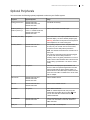
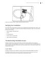
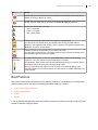
LifeSize® Video Communications Systems
Installation Guide
February 2012
LifeSize Room 220
LifeSize Room 220i
LifeSize Team 220
LifeSize Express 220
LifeSize Video Communications Systems Installation Guide
Preparing for Installation
As you prepare to install your LifeSize video communications system, consider the physical conditions of
the room, compatibility with displays and your network configuration and settings. Related documentation
is available from lifesize.com/support.
Before You Install
If you are not using DHCP, you might need guidance from your network administrator to complete the initial
configuration. You will need to manually set an IP address, subnet mask, and default gateway for your
LifeSize system.
Network Bandwidth
Poor audio and video quality might result from insufficient bandwidth on your network. LifeSize
recommends that your network be capable of at least 1 Mb/s (incoming and outgoing) for a high definition
video call. During video calls with lower bandwidths, LifeSize systems automatically select the best
resolution that can be achieved with the available bandwidth.
Domain Name Service Server
If you intend to use domain addresses for placing calls, either configure a DNS server or use a DHCP
server that automatically sets a DNS server.
Room Configuration
The size, shape, layout, and occupancy of the room dictate where you place your video conferencing
components. For example, in a multi-user conference room, place a LifeSize MicPod or LifeSize Phone at
the center of the group of participants.
All LifeSize codecs except LifeSize Room 220i can be locked with a secure loop to prevent physical
removal of the device. For assistance, contact your LifeSize Partner or LifeSize Customer Support.
WARNING
Avoid routing cables from the codec across foot-traffic areas. Tripping on
the cables can cause personal injury as well as permanent damage to the
connectors in the cables and the codec itself.
The lighting in your environment affects image quality. The optimal lighting for LifeSize systems is 300 to
500 LUX. If light levels are set too low, consider adding artificial light. Indirect light from shaded sources or
reflected light from pale walls often produces excellent results. Avoid the following:
•
direct sunlight on the subject matter, background, or camera lens
•
direct illumination of the subject matter and camera lens
•
colored lighting
•
harsh side lighting or strong light from above
2
LifeSize Video Communications Systems Installation Guide
System Components
Your package contains the following components:
•
LifeSize codec and power supply unit (PSU)
NOTE
The LifeSize Room 220i does not feature a PSU. Instead, a power cord plugs
directly into the back of its chassis.
•
Codec stand (LifeSize Room 220 and LifeSize Team 220 only)
•
LifeSize remote control, including three AAA batteries
•
Standard cable kit
You can substitute cables of longer lengths with the following limits:
-
HDMI: 15 meters (49 feet)
-
Ethernet: 100 meters (328 feet)
Read Cables for more information.
•
Quick reference card (QRC)
•
Documentation CD
Depending on the package that was purchased, one of the following audio components might also be
included:
•
LifeSize Phone
•
LifeSize MicPod (includes strain relief clip)
Similarly, your package might include the LifeSize Camera 10x, along with a power supply and standard 3
meter (9.8 foot) HDMI cable.
Rack Mounting Considerations
You can mount LifeSize Room 220i without the use of rails. Before you install the system in a rack,
however, consider the following:
Consideration
Description
Rack stability
Ensure that the leveling jacks on the bottom of the rack are fully extended to the floor when
the full weight of the rack rests on them. In a single rack installation, attach stabilizers to the
rack. In multiple rack installations, couple the racks together.
Airflow and access
Leave approximately 75 centimeters (30 inches) of clearance behind the rack to allow for
sufficient airflow and ease in servicing.
Ambient operating
temperature
If you install the device in a closed or multi-unit rack assembly, the ambient operating
temperature of the rack environment might be greater than the ambient temperature of the
room. Consider installing the equipment in an environment that is compatible with the
manufacturer’s maximum rated ambient temperature.
3
LifeSize Video Communications Systems Installation Guide
Consideration
Description
Circuit overloading
Consider the connection of the equipment to the power supply circuitry and the effect that
any possible overloading of circuits might have on overcurrent protection and power supply
wiring. Give appropriate consideration to equipment nameplate ratings when addressing
this concern.
Reliable ground
Maintain a reliable ground at all times. (It is recommended that you ground the rack itself.)
Pay particular attention to any power supply connections other than the direct connections
to the branch circuit, such as a power strip.
Installing Your System
Before you install your system, read the LifeSize Safety and Regulatory Notices for important safety
information.
WARNING
Exercise care when connecting cables to the codec. Face the back of the
codec or ensure that all connectors are visible when connecting a cable to
the codec.
To install your LifeSize system, remove all components from the product packaging and place them in the
appropriate positions in your conference room or office.
WARNING
Do not place objects that can generate heat or obstruct airflow in front of
or behind a codec. (If the unit is not mounted in a rack or stand, do not
place anything on top of or below it, as well.) Such placement can cause
the system to overheat and restart. Further, prolonged overheating can
damage the codec. Make sure the room that houses the codec features a
controlled temperature and is well ventilated.
Optional, for LifeSize Room 220 and LifeSize Team 220 only: Insert the codec into its stand by aligning the
pin holes at the base. Secure the codec by tightening the bolt on the bottom of the stand. It is further
recommended that you insert the rubber feet into the bottom of the stand.
WARNING
Use the stand and bolt included in the product box. Using a stand and bolt
from another LifeSize model can damage the codec.
When you use the stand, LifeSize recommends that you route the thicker cables (DVI and HDMI) through
the plastic strain relief guide on the stand to enhance the stability of the codec and to prevent tipping. You
can also remove the stand and lay the codec flat to improve stability.
4
LifeSize Video Communications Systems Installation Guide
Optional, for LifeSize Room 220i only: The codec includes two rack mounting brackets that are located on
each side at the front of the chassis. To mount the device in a rack unit, screw these brackets directly to the
front of the rack. Two screws are required for each bracket. Read Rack Mounting Considerations for more
information.
Refer to the QRC that is included with your system for a visual depiction of the appropriate setup. The
numbers that appear on the QRC correspond to the following steps:
1. Open the battery compartment on the back of the remote control.
a. Before inserting the batteries, stretch each of the two straps across the outer battery slot closest to
to the battery.
b. Insert the two outer batteries, negative end (-) first against the spring, and press the positive (+)
end into place, thereby trapping the cloth straps beneath the batteries.
c. Lay the longer cloth strap over both batteries and insert the center battery’s negative end against
the spring to trap the longer cloth strap beneath it. Press the positive end of the battery into place.
d. Lay the ends of the cloth straps over the center battery and install the cover.
2. To connect your LifeSize camera to the codec, insert the HDMI cable into the HD port on the camera
and plug the opposite end into the appropriate port on the codec:
-
LifeSize Room 220 and LifeSize Team 220: HD in 1
-
LifeSize Room 220i: HDMI-to-DVI cable in 1
-
LifeSize Express 220: HD in
port
port
port
Insert the power adapter cable into the power port on the back of the camera, and plug the power
adapter into a power outlet.
Optional: Install the glare visor, using the notches on the lens barrel to guide the visor into its correct
position. Use the visor only if it improves the image in your environment.
CAUTION
Do not attempt to pick up the camera by the glare visor, as it might pull
loose and subject the camera to damage or destruction from a fall.
3. Insert the appropriate end of either the display cable (HDMI or DVI-I to HDMI) into the port on the rear
of your display and the opposite end into the Display 1 HD
port. (If you are using
LifeSize Room 220 or LifeSize Team 220 with a stand, LifeSize recommends you route this cable
through the strain relief guide on the stand.) Insert the display power cord into a power outlet. To
connect a second display, refer to Configuring a Second Display.
NOTE
LifeSize Express 220: If you plan to use external speakers that are not built
into the display, connect the speakers to the port marked with the line out
symbol
on the back of the codec.
4. Insert the network cable into the network port marked with the LAN symbol
on the back of the
codec. Insert the opposite end of the network cable into a network port on the wall.
5
LifeSize Video Communications Systems Installation Guide
5. Perform one of the following steps:
-
If you are using the LifeSize Phone for audio, insert the phone cable into the port marked with the
LAN symbol
on the underside of the phone. Six Phoenix connector plugs are provided for
connecting balanced audio inputs and outputs.
NOTE
The exterior port marked with the
reserved for future use.
symbol on the LifeSize Phone is
Insert the opposite end of the phone cable into the port marked with the LifeSize Phone symbol
on the back of the codec. Ensure the cables are secured into the guides to avoid damaging
the cables.
NOTE
-
When the LifeSize Phone is connected to a LifeSize system, you cannot
configure it as a standalone speakerphone. Instead, use the system interface
to configure your system.
If you are using a single LifeSize MicPod for audio, insert the end of the cable from the
LifeSize MicPod into the microphone port marked with the microphone symbol on the back of
the codec. If you are using LifeSize Room 220 or LifeSize Team 220 with a stand, LifeSize
recommends you route this cable through the strain relief guide on the stand.
Optionally, you can add a LifeSize MicPod extension cable (not included) to the LifeSize MicPod.
The extension cable is 15 meters (49 feet), and LifeSize recommends using no more than one
extension cable.
WARNING
LifeSize recommends that you use the cable strain relief clip included with
LifeSize MicPod, as described in Attaching the LifeSize MicPod Strain
Relief Clip.
If you are using dual LifeSize MicPods for audio, refer to Configuring Dual LifeSize MicPods.
6. Insert the cord from the power adapter into the power outlet marked
on the back of the
codec (near the base). Insert one end of the power cord into the power adapter and the opposite end
into a power outlet on the wall. See Status Icons for more information about the state of the system as
it boots or as conditions change.
NOTE
The LifeSize Room 220i does not require an external PSU. Instead, a power
cord plugs directly into the back of its chassis, which features a power switch
near the cord input.
The LifeSize system starts and illuminates a blue LED on the front of the codec. The system status bar
at the bottom of the screen indicates system and network status. When the system is booting, status
also appears at the top of the Redial list to indicate the current state of the system.
6
LifeSize Video Communications Systems Installation Guide
The camera initializes the first time it is connected to a codec. This process takes approximately 90
seconds.
WARNING
Top avoid damaging the system, do not disturb or disconnect the devices
during this time.
7. An Initial Configuration screen prompts you to configure the system.
Refer to the LifeSize Video Communications Systems User and Administrator Guide to complete the
initial configuration. If the initial configuration screen does not appear and the display is blank, refer to
Troubleshooting Installation Issues.
Placement Behind a Firewall
Refer to the LifeSize Video Communications Systems User and Administrator Guide for information about
configuring the system for firewall traversal.
Connecting a PSTN Phone Line
If you chose the Touch Tone option for the Voice Dialing preference during the initial configuration of
LifeSize Room 220, LifeSize Room 220i, or LifeSize Team 220, ensure that you connect one end of an RJ11 PSTN phone cord to the PSTN phone port labeled
on the LifeSize codec and the other end to a
phone jack on the wall.
Supported Display Types and Resolutions
LifeSize video systems connect to HD displays (720p minimum), including:
•
plasma, LCD, and LED flat panel displays
•
large screen rear projection TV displays (720p/1080p displays)
•
front projection displays
•
rear projector A/V room configurations
Supported display resolutions include the following:
Display 1
1280 x 720p60
1280 x 768p60
1920 x 1080p30
1920 x 1080i60
Display 2
1280 x 720p60
1280 x 768p60 (LifeSize Room 220, LifeSize Room 220i, and
LifeSize Team 220 only)
1920 x 1080p30
1920 x 1080i60
7
LifeSize Video Communications Systems Installation Guide
The primary output defaults to 720p60 and works with most 720p HD displays. Learn how to change the
resolution for 1080 HD displays in Changing Display Resolution.
LifeSize recommends using a dual display configuration for presentations.
NOTE
The Display 1 Resolution and Display 2 Resolution preferences in
Appearance : Displays default to Auto if you select an option for these
preferences that the connected display does not support. If the resolutions are
not the same, Display 2 is limited to displaying presentations and is unable to
mirror the primary display or display calls. For more information, see
Configuring a Second Display.
Changing Display Resolution
The primary output defaults to 720p60 and works with most 720p HD displays.
To change the display resolution, navigate to Administrator Preferences : Appearance : Displays and
choose Display 1 Resolution. You can change the resolution to 1920x1080i60 or 1920x1080p30 for a
value that works with most 1080 HD displays.
NOTE
Before you change the display resolution to 1920x1080p30, ensure that you
can access the Display 1 Resolution preference using one of these
methods.
If an 1080p display does not work with 1080p30 mode, the display might appear blank. In this case,
configure the display resolution from either the LifeSize Phone (refer to Blank or Distorted Display) or from
the web administration interface.
Configuring a Second Display
To connect a second display, insert the video display cable into the port on the rear of your display and the
opposite end into the Display 2 HD 2 port on the codec. (If you are using LifeSize Room 220 or
LifeSize Team 220 with a stand, LifeSize recommends you route this cable through the strain relief guide
on the stand.) Attach the display power cord to a power outlet. By default, the second display is blank.
Navigate to Appearance : Layout and choose Display 2 Layout, which by default is set to None.
•
Choose Presentations + DVI-I Input to display presentations (local and remote) during a call that is
sending or receiving a presentation. When not in a call, the background image appears in the display.
•
Choose Calls + Presentations + DVI-I Input to display:
-
video images from video calls
-
presentations (local and remote) in a call that is sending or receiving a presentation
-
background image when not in a call
8
LifeSize Video Communications Systems Installation Guide
•
Choose Simulcast Calls + DVI-I Input to show the same output on Display 2 as shown on Display 1
during calls.
If you use a VGA projector as Display 2, navigate to Administrator Preferences : Appearance :
Displays and choose Display 2 Resolution. Configure its resolution to 1280 x 768 to match the default
HD configuration of Display 1.
NOTE
To use the Calls + Presentations + DVI-I Input or Simulcast Calls + DVI-I Input
options, set Display 1 and Display 2 to the same resolution; otherwise, the
value is forced to Presentations + DVI-I Input.
The following conditions apply when using two displays with LifeSize Express 220:
•
The presentation icon that appears on screen during a call to indicate that a near or far end
presentation is in progress appears in Display 1. For a presentation sent from a far end participant, the
receiving presentation icon
appears in the upper left corner of Display 1. For a presentation sent
from the near end, the sending presentation icon
appears in the lower right corner of Display 1.
•
If you choose Calls + Presentations + DVI-I Input or Simulcast Calls + DVI-I Input for the Display 2
Layout preference, the following status icons and information do not appear in video images in the
second display during calls:
-
caller ID information and call type (voice or video) icons
-
camera selection icons
NOTE
Selecting a camera to control by pressing the near/far camera button on the
remote control during a call shows no indication of which participant’s camera
is selected if the participant’s video image appears only in the second display.
-
encryption icons
-
mute icon
•
Only presentation video or DVI-I input is supported for Display 2. Background image and color
preferences that appear in Appearance : Backgrounds are available for Display 1 only. The user
interface appears only in Display 1.
•
When the logo screen saver is active on the primary display, the second display shows the background
image instead of the screen saver.
9
LifeSize Video Communications Systems Installation Guide
Optional Peripherals
You can connect the following optional peripherals to enhance your LifeSize system:
Peripheral
Supported Systems
Usage
Analog phone line in
LifeSize Room 220,
LifeSize Room 220i, and
LifeSize Team 220
For PSTN connectivity.
Audio In (Line In) 1
Line In - All systems
With an external line level audio input.
Audio In (Line In) 2
Line In 2 - LifeSize Room 220,
LifeSize Room 220i, and
LifeSize Team 220
Audio Out (Line Out)
All systems
With external line level output speakers that are not
built into display 1 or with a headset (left plus right).
Warning: Excessive sound pressure from earphones
and headphones can cause hearing loss.
Auxiliary Video In
LifeSize Room 220 and
LifeSize Room 220i
For inputting component video, composite video, or
S-video, only one of which can be used at a time;
component source always takes precedence.
Note: The LifeSize Room 220i does not feature an Svideo port.
If S-video and composite sources are both plugged
in, the S-video source takes precedence.
Auxiliary Video In is typically used either to connect a
DVD or VCR to share standard video content with the
far end during a presentation or to view the content
locally.
DVI-I In (PC in)
All systems
With devices and laptops for presentations or to
share PC data. Accepts both digital video and VGA
analog signals with the proper adapter cable. For
devices and PCs with VGA output, LifeSize includes
a DVI-A to VGA cable. An HDMI source can be used
with an adapter.
HD Camera
LifeSize Room 220 and
LifeSize Room 220i
With a LifeSize camera.
LifeSize Team 220
HD in 2
LifeSize Room 220 and
LifeSize Room 220i
Networker
All systems
With a second LifeSize camera.
With LifeSize Networker.
Note: On LifeSize Express 220, this port is also
marked with the LifeSize Phone symbol
and
can be used with either LifeSize Phone or
LifeSize Networker.
Serial RS-232
LifeSize Room 220 and
LifeSize Room 220i
With supported third-party cameras using VISCA
control or for automation control with Crestron or
AMX controllers.
USB port
All systems
Used for USB to serial adapters.
10
LifeSize Video Communications Systems Installation Guide
Configuring Dual LifeSize MicPods
In a dual LifeSize MicPod configuration, you use a combination of two LifeSize MicPods, one splitter cable,
and extension cables in large rooms for maximum omnidirectional audio coverage.
You cannot use multiple splitters to connect to more than two LifeSize MicPods. However, you can use
variations on three configurations of extension cables:
•
If you connect the male end of the splitter directly to the codec, you can use either none or one
extension cable to connect a LifeSize MicPod to each of the female ends of the splitter.
•
If you use one extension cable to connect the codec to the splitter, you can use either none or one
extension cable to connect a LifeSize MicPod to each of the female ends of the splitter.
•
If you use two extension cables to connect the codec to the splitter, connect both LifeSize MicPods
directly to the female ends of the splitter.
WARNING
LifeSize recommends that you use the cable strain relief clip included in
the LifeSize MicPod product box as described in Attaching the
LifeSize MicPod Strain Relief Clip to avoid personal injury or damage to
the unit.
A LifeSize codec detects any splitter or cable attached to the microphone input of the codec as a
LifeSize MicPod. If a LifeSize MicPod is not attached to the extension or splitter cable and the microphone
input is selected as the active microphone, no audio is available. The
indicator does not appear in the
status bar, and the Active Microphone field on the System Information page reports Microphone In as
the active microphone.
Attaching the LifeSize MicPod Strain Relief Clip
If the LifeSize MicPod is installed in an area where you could pull or trip over the cord, LifeSize
recommends using the strain relief clip included with your LifeSize MicPod to reduce the chance of
disconnecting or damaging the plug or the system codec.
Ensure that the codec surface is dry and free of dirt, dust, oil, and other residues. The adhesive tape on the
strain relief clip is intended for a single use. Attach the strain relief clip to the codec and route the
LifeSize MicPod cable through the strain relief clip, as shown in the following illustration.
11
LifeSize Video Communications Systems Installation Guide
Contact your LifeSize Partner to obtain a replacement strain relief clip.
Verifying Your Installation
The LifeSize Video Communications Systems User and Administrator Guide explains how to place a test
call to verify your installation. The guide also describes additional configuration steps if your environment
uses any of the following:
•
Network Address Translation (NAT)
•
firewall
•
H.323 gatekeepers
•
Session Initiation Protocol (SIP)
•
other network security systems
Troubleshooting Installation Issues
Installation issues that you might encounter with your LifeSize system typically involve improperly
connected cables, network bandwidth, or connectivity. For more information about troubleshooting issues
that you might encounter with LifeSize systems, refer to the LifeSize Video Communications Systems User
and Administrator Guide.
Loose Cables
Improperly connected or loose cables are common causes of problems with hardware units. When
investigating a system problem, inspect the external controls and cable connections. Ensure that
connections are correct and secure and that nothing is obstructing the cables.
12
LifeSize Video Communications Systems Installation Guide
Blank or Distorted Display
If your screen image is distorted and unusable, or if the display is blank, perform the following steps to
configure the display from the web administration interface:
1. Enter the IP address of your system in a browser.
NOTE
Ignore any warnings on security certificates.
2. Navigate to Preferences : Appearance : Displays.
3. For Display 1 Resolution, select Auto.
4. Select Save Changes and Log out.
No Power
Perform the following steps to troubleshoot a power problem:
1. Disconnect the PSU from the LifeSize codec and the AC source.
NOTE
The LifeSize Room 220i does not feature an external PSU. Instead, turn off
the power switch and disconnect the power cord.
2. Plug a working appliance into the AC source to determine whether the source is functioning.
3. If the AC source works, plug the PSU into the AC source, but do not connect the PSU to the LifeSize
codec. If the green LED on the PSU illuminates, the PSU is probably functioning.
4. Disconnect the PSU from the AC source; connect the PSU to the LifeSize codec; and reconnect the
PSU to the AC source. If the LifeSize codec fails to boot and the green LED on the PSU dims, the
codec might be the source of the problem.
IP Address Displays Invalid Value
If the IP address that appears at the top of the main screen displays an invalid value after you complete the
initial configuration, one of the following conditions might exist:
Condition
Resolution
The unit is configured to obtain an address using
DHCP, but no DHCP server is available.
Verify that the unit is plugged into a network that has a
DHCP server present.
Note: The DHCP client self-assigns an address in
the 169.254 class B network, and the red network
symbol
appears in the status bar on the main
screen.
Faulty Ethernet cable connection.
Replace the Ethernet cable with a high quality cable.
13
LifeSize Video Communications Systems Installation Guide
Condition
Resolution
The unit is configured to use a static IP address, but
no IP address has been entered.
Identify and enter the necessary IP information.
Network connection is unavailable.
Inspect your network connection.
A red network symbol
on the main screen.
appears in the status bar
Camera Issues
Video from the camera appears in a small window on the main screen of the user interface above the
Redial list. If no video from the camera appears, perform the following steps:
1. Ensure that the camera is properly connected to the LifeSize codec, as described in Installing Your
System.
2. Verify that the blue LED on the front of the camera is lit and not blinking.
3. From the main screen of the user interface, press
to access the System Menu. Press
to
access page 2 of the System Information page. Ensure that the status of the camera is Ready.
4. Ensure that the primary input is set to the high definition camera. Press
. If Primary Input : HD
Camera does not appear at the top of the screen, press
to display the Primary Input selection
dialog. Use the arrow keys on the remote control to select the appropriate high definition camera and
press OK.
Improving a Dim Image
Adjust the HD Camera Brightness preference in Diagnostics : High Definition Camera. You can also
add a light source to improve the subject’s illumination. Read more at Room Configuration.
Attached Video Input Device Not Working
When you connect a video input device with capabilities that the LifeSize system does not support, the
status Out of range appears on the System Information page for that input. The device might be in a
mode that the codec does not support. If changing the mode does not help, the device is not supported.
Status Icons
The following table identifies the icons that can appear in the system status bar.
Icon
Condition
Indicates that the communication subsystem is initializing. If this icon reappears after the
system has booted, a problem has occurred. Restart the system.
Indicates that the system is initializing. When the system is initializing, functionality on the main
screen is disabled, and no entries appear in the Redial list. This icon also appears when a new
device is connected to the system after the system boots and disappears when the device is
ready. If the icon persists, a problem has occurred. Restart the system.
14
LifeSize Video Communications Systems Installation Guide
Icon
Condition
Indicates that the connected phone has been detected and is initializing. If the icon persists, a
problem has occurred. Restart the system.
Indicates that the system does not have an active microphone. Check the device’s connections
and then check the option that you selected for the Active Microphone preference.
Network Status
Identifies the network status, as follows:
• Green – Connected
• Yellow – In Progress
• Red – Disconnected
Indicates the status of the registration process with the H.323 gatekeeper.
The yellow H.323 icon appears when your LifeSize system is trying to register with the
gatekeeper. If the registration fails, the red H.323 icon appears. If the system is registered to a
gatekeeper, the system shows its status.
Indicates the status of the registration process with the SIP server.
The yellow SIP icon appears when your LifeSize system is trying to register with the SIP server.
If the registration fails, the red SIP icon appears.
System
Overheating
The yellow indicator warns you when the system temperature is above normal operating
temperature. The codec adjusts fan speed automatically to cool itself.
The red indicator warns that the system is overheated and approaching the maximum allowed
operating temperature, at which point it will automatically restart.
Warning: Temperatures that require the codec to restart can permanently damage codec
components. Make sure the room that houses the codec features a controlled temperature and
is well ventilated.
Best Practices
This section recommends best practices for the planning, evaluation, and installation of a LifeSize video
communications system. Consider the following topics when setting up a system:
•
Video Conferencing Environment
•
Component Placement
•
Cables
•
Echoes
If you are installing a telepresence room with LifeSize Conference or LifeSize Conference 200, refer to the
LifeSize Conference Integrator Guide.
15
LifeSize Video Communications Systems Installation Guide
Video Conferencing Environment
The characteristics of the rooms in which you install your video communications systems influence many
of the choices that you need to make regarding the placement of your components. For example, the
configuration of a room might affect how you answer the following questions:
•
Will the environment feature a single display or a dual display? Where is the most ideal location for
your displays? Does the room include a projector?
•
Will everyone be visible to the camera and have a clear view of the display?
•
Consider potential cabling issues for audio, video, and network. Do you need lengths beyond the
cables that were shipped with your LifeSize components? How do you intend to conceal the cables?
Can they be run around furniture, through walls, or under carpet?
•
Does the codec need to be concealed? Can it be rack mounted?
LifeSize systems are often placed in office conference rooms that were not designed to readily
accommodate video conferencing. As a result, it is recommended that you diagram a room before you
start setting up your video conferencing environment. A diagram that includes the following objects and
information can help you make decisions about component choice and placement:
•
overall dimensions of the room
•
windows and other light sources
•
doors
•
power outlets
•
LAN/PSTN outlets
•
air vents
•
current seating arrangement
The following sections about Audio and Lighting issues describe the importance of most of these items.
Read Cables for more information about power outlets and LAN/PSTN outlets.
Audio
Sound Reflecting Surfaces
Windows and other hard surfaces, such as brick, wood paneling, and concrete, are highly reflective and
can cause audio to sound tinny. Consequently, LifeSize recommends that you do not place audio input
devices close to walls or windows if those devices are designed to detect sound from all directions, like the
LifeSize Phone and LifeSize MicPod. Instead, place such devices in the center of the room and arrange
participants at least four feet away from the input. Clear a radius of 2 feet around the input to minimize
reflectivity. Hang blinds, shades, or curtains from windows to absorb sound and further reduce reflectivity.
Standard sheetrock or drywall (1/2 inch or 5/8 inch thickness) with a smooth surface is recommended, as
are standard business office acoustic ceiling tiles, which help to absorb reverberation and undesired
sound. Standard office carpeting is also recommended to reduce reverberation, while sound reflective
surfaces like Linoleum and hardwood are not recommended.
16
LifeSize Video Communications Systems Installation Guide
Noise Sources
Keep audio input devices away from sources of noise, like air vents and any components that house fans
or motors. On the HVAC, sound dampening registers and baffles are recommended to help reduce noise
from the flow of air in the ventilation system.
Speakers
Keep speakers and other audio output devices at least 4 feet away from audio input devices.
Audio Coverage
Different audio input options are designed to cover different areas and patterns, as follows:
•
LifeSize MicPod possesses an optimal coverage radius of 10 feet, making it ideal for a room in which
participants are located within 10 feet of the device (like a 20 x 20 foot room).
•
LifeSize Phone possesses an optimal coverage radius of 15 feet, making it ideal for a room in which
participants are located within 15 feet of the device (like a 30 x 30 foot room).
•
For a room that is longer than it is wide, the LifeSize Dual MicPod configuration can cover a 20 x 40
foot room. Read Audio Input Device for more information.
•
LifeSize Focus features two built-in microphones that minimize audio signals from behind the camera
while maximizing signals in the camera’s field of view (70 degrees) between 0.5 meters (1.5 feet) and
2.5 meters (8.2 feet) away. Focus is designed to reside at one end or corner of a small office or cubicle
(10 x 10 feet).
Lighting
For best results, LifeSize recommends that participants be lit to 350-500 LUX. (One LUX is the equivalent
of 1 Lumen spread over 1 square meter.) Be aware that the intensity of light decreases at a rate that is
proportional to the square of the distance from the source.
LifeSize also recommends that you use only one quality of light. Avoid using natural light, which changes
location and intensity throughout the day. It is also recommended that you avoid mixing daylight with
artificial light or mixing different light temperatures.
Overhead fluorescent lights might provide sufficient lighting if they are concentrated over the conference
room table. However, such lights can cause unacceptable shadows if they are located behind or directly
above the participants. Replace or augment overhead lighting with lights that are directed at the
participants.
Key and Fill Lighting
If you choose to augment the room’s lighting, make certain to use lights with the same color temperature
as the overhead lights. Place the lights at or behind the plane of the camera and slightly above camera
height, at a 30 to 60 degree angle to the camera, and focused on the participants. Traditionally, a key light
is the main light source on one side of the camera, and a fill light is a secondary source from the other side
of the camera. Fill lights even out (or fill in) shadows that a key light casts. Aim fill lights at the same angle
to the camera as the key light but lower than the height of the camera.
17
LifeSize Video Communications Systems Installation Guide
Component Placement
This section identifies ways to help you decide where to place the following components of your LifeSize
communications system:
•
Codec
•
Audio Input Device
•
Audio Output Device
•
Camera
•
Video Display
Codec
Most LifeSize codecs are designed to be set top devices that lie horizontally or vertically on a stand.
Nonetheless, you can use specialized shelving to obtain the security and airflow benefits of rack mounting.
In any case, consider the minimum vent clearance, power consumption, and codec weight when you
decide how and where to place a codec.
After you place a codec in an appropriate location, follow the guidelines in the rest of this section to ensure
that it performs at an optimal level.
Audio Input Device
LifeSize Phone
Follow these guidelines to obtain the best possible performance from the LifeSize Phone:
•
Place the phone in the center of the room and in the center of the conference table.
•
Keep objects that might block acoustical signals, like plants, laptops, or lamps, more than two feet
away from the phone.
•
Keep noise sources, such as speakers and components that house fans or motors, at least four feet
away from the phone.
•
Do not place the phone directly underneath or beside acoustically reflective surfaces, such as walls,
glass tables, or windows.
•
Place the phone at least two feet away from the closest participant.
•
Position the phone so that participants are within 0-45 degrees of the table surface.
•
Avoid moving the phone during a call.
•
Avoid movement within two feet of the phone.
•
Speak at normal conversation levels and direct your voice toward the phone.
•
Avoid speaking directly above the phone.
For more information about installing, using, and troubleshooting the LifeSize Phone, refer to the LifeSize
Phone User Guide.
18
LifeSize Video Communications Systems Installation Guide
Single LifeSize MicPod
Follow these guidelines to obtain the best possible performance from a single LifeSize MicPod:
•
Place the MicPod in the center of the conference table.
•
Position the MicPod at least three feet away from any active speakers, such as the speaker on a
LifeSize Phone or LifeSize Room device.
•
Keep objects that might block acoustical signals, like plants, laptops, or lamps, more than two feet
away from the MicPod.
•
Keep noise sources, such as speakers and components that house fans or motors, at least four feet
away from the MicPod. The MicPod picks up noise in all directions equally.
•
Place the MicPod at least two feet away from the closest participant.
•
Avoid movement within two feet of the MicPod.
Dual LifeSize MicPods
To obtain the best possible performance from dual LifeSize MicPods, place the MicPods at least 10 feet
apart on a table surface and follow the guidelines in Single LifeSize MicPod.
LifeSize Focus
Follow these guidelines to obtain the best possible performance from the LifeSize Focus:
•
Position the Focus at least 18 inches away from any active speakers, such as the speaker on a
LifeSize Phone or LifeSize Room device.
•
Point the Focus toward the participants.
•
Keep noise sources, such as speakers and components that house fans or motors, from moving
between the Focus and the participants.
•
If the Focus is attached directly to a monitor with speakers, vibration from the monitor’s speakers might
cause an induced echo. Move the Focus away from the monitor and ensure that it is not placed directly
in front of an active speaker. Read Echoes for more information.
Audio Output Device
Use any of the following speaker types to listen to audio output:
•
internal speakers that are built in to a display
•
external speakers
•
speaker on the LifeSize Phone (not recommended)
Follow these guidelines to obtain the best possible performance from your audio output devices:
•
Use only speakers that provide a flat frequency response and a linear output signal.
•
Position all speakers at least five feet from the microphones, regardless of the type of device that you
use.
19
LifeSize Video Communications Systems Installation Guide
•
Adjust the speaker volume to 40-50% of its maximum value. Speakers often produce distorted output
when the volume is set to a value that is greater than 60% of the maximum, and distorted output can
cause acoustic echo. Read Echoes for more information.
•
Avoid Dolby or surround sound speakers, which can change their speaker signal and generate
echoes.
Camera
In most cases, LifeSize recommends that you mount the camera in coordination with the display to provide
as close to an eye-to-eye experience as possible. Follow these positioning guidelines:
•
Position the camera in the center of the primary display.
•
Place the camera immediately below or above the primary display. In most cases, the position
immediately below the display is preferable.
•
Place the camera far enough from the participants so that everyone is captured within the camera’s
field of view (70 degrees for LifeSize cameras).
Video Display
The video display that you choose for a conference room depends on many factors. One important
criterion, though, involves making certain that the display’s input matches the video communications
system’s output. The following table shows the output connectors and video displays that are associated
with various LifeSize video communications systems.
LifeSize VCS
Output Connector
Display
LifeSize Room (both
displays), LifeSize
Team MP
VGA
HD resolution displays with VGA or component inputs (at least
native 1280 x 720).
LifeSize Room 200 and
LifeSize Room 220
(both displays),
LifeSize Team 200 and
LifeSize Team 220
HDMI (primary)
1080i/720P resolution HD displays with HDMI or DVI-I inputs.
DVI-I (secondary)
1080 resolution projector with HDMI or DVI-I inputs (optional for
second display).
LifeSize Room 220i
DVI-D (primary)
HD resolution projector with a 16:9 aspect ratio with component
inputs (optional for LifeSize Room second display).
HDMI (secondary)
LifeSize Express 200
(both displays), LifeSize
Express, LifeSize Team
200
HDMI
720P resolution HD displays with HDMI inputs.
Consider whether a display provides participants with a comfortable experience. The following factors
influence the optimal size of a display:
•
size of the room
•
participants’ distance from the display
20
LifeSize Video Communications Systems Installation Guide
•
level of required detail
•
budget
If the camera is centered on the top or bottom of the display, LifeSize recommends that you position the
display so that its top is as high as the forehead of a typical participant.
Cables
LifeSize systems are shipped with some or all of the following cables:
•
Power cable – Every LifeSize system ships with a 2 M power cable. Use an extension cord for longer
runs.
•
Ethernet or LAN cable – Every LifeSize system ships with a 3 M RJ45 Ethernet/LAN cable. This cable
is standard and can be replaced by a longer RJ45 LAN cable (up to 100 meters).
•
LifeSize Phone cable – LifeSize Phone ships with a 9 M shielded Ethernet cable with a shorter than
normal RJ-45 connector, which is easier to insert into the recessed connector on the LifeSize Phone. If
you need a longer cable, replace this one with any shielded Power-over-Ethernet cable (up to 100
meters).
•
LifeSize MicPod cable – The LifeSize MicPod ships with a 7.5 M cable. LifeSize also offers a 15 M
extension cable. You can use two extension cables to extend the range of a single MicPod to a
maximum of 37.5 M.
The standard dual MicPod configuration features two LifeSize MicPods, a splitter, and one 15 M
extension cable. Extension cables in a dual MicPod configuration can be set up in any of the following
manners:
-
If you connect the male end of the splitter directly to the codec, use no extension cables or one
extension cable to connect a LifeSize MicPod to each of the female ends of the splitter.
-
If you use one extension cord to connect the codec to the splitter, use no extension cables or one
extension cable to connect a LifeSize MicPod to each of the female ends of the splitter.
-
If you use two extension cables to connect the codec to the splitter, connect both LifeSize MicPods
directly to the female ends of the splitter.
A strain relief strap is included with the LifeSize MicPod. Follow the appropriate instructions to attach
the strap and route the cable through it.
Base cables, extension cables, and the splitter are proprietary (power as well as audio are transmitted)
and cannot be replaced with third-party pieces.
•
PSTN cable – The LifeSize Room and LifeSize Team families feature analog phone jacks and ship
with a 3 M RJ11 cable. Use a longer cable if you require a longer run.
•
Display cable – All of the display cables that ship with LifeSize systems are 3 meters in length and can
be extended or replaced as follows:
-
Extending an HDMI cable – Replace the included 3 M cable with an industry standard HDMI cable
up to 15 meters in length. If you need an even longer cable, LifeSize recommends using an HDMI
extender. The Geffen HDMI Cat-5 MS Extreme Extender has been tested with two 15 M HDMI
21
LifeSize Video Communications Systems Installation Guide
cables (one from the codec to the Geffen transmitter, and one from the Geffen receiver to the
display) and two 45 M Cat-5 UTP cables in parallel between the transmitter and the receiver (one
for the display data channel and one for the video channel).
•
-
Extending a DVI-I (or DVI-I to HDMI) cable – Replace the included 3 M cable with an industry
standard DVI-I or DVI-I to HDMI cable up to 15 meters in length. If you need an even longer cable,
use the method described in the previous list item.
-
Extending a VGA (HD-15) to component cable – If you need to extend the VGA to component
cable, LifeSize recommends that you do not replace the included cable. Instead, extend each
component output with high-grade RG-6 cables up to 100 meters.
-
Extending a VGA (HD-15) to VGA (HD-15) cable – If you need to extend the VGA to VGA cable,
LifeSize recommends that you do not replace the included cable. (Third-party VGA cables can
result in poor performance.) Instead, connect the included cable to a female to female adapter and
then connect a VGA cable to reach the appropriate length.
Camera cable – The LifeSize camera cable that ships with LifeSize Camera and LifeSize Focus
features the same connector as a FireWire cable. However, the LifeSize camera cable is a proprietary
cable and, consequently, is not interchangeable with standard FireWire cables. The maximum cable
length for these cameras is 15 meters.
Use an HDMI cable to support the 720P60 or 1080P30 resolutions on the LifeSize Camera 200. You
can use an industry standard HDMI cable of up to 15 M to extend the cable run. If you require
additional length, LifeSize recommends using an HDMI twisted-pair extender, such as the Extron
HDMI 201 Twisted-Pair Extender. Use a 3 M HDMI cable from the codec to the first Extron converter
and another 3 M HDMI cable from the second Extron converter to the LifeSize Camera 200. Use two
45 M CAT-5 cables in parallel between the 2 Extron converters.
When used with HDMI, the LifeSize Camera 200 requires a separate power cable that can be
extended by a heavy-duty extension cord of up to 100 feet. HDMI camera cables do not function with
HDMI switches.
•
RCA cable – LifeSize Room and LifeSize Team MP come with a 3 M stereo RCA cable for audio out.
LifeSize Room also comes with a 3 M mono RCA cable. You can replace these cables with industry
standard RCA cables.
•
VGA/DVI-A cable – LifeSize Room, LifeSize Team MP, and LifeSize Express come with a 3 M VGA to
VGA video input cable with green connectors to connect the codec to PCs, Macs, and other video
input devices.
LifeSize Room 220, LifeSize Room 220i, LifeSize Team 200, and LifeSize Express 200 come with a
3 M VGA to DVI-A video input cable with green connectors to connect the codec to PCs, Macs, and
other video input devices.
Avoid routing cables through areas that experience heavy foot traffic. If possible, use a cable management
system to encase the cables and make them difficult to move when someone comes into contact with
them. These measures can mitigate the damage that might be caused by people tripping on cables and
straining the connectors on the codec.
LifeSize cables are not plenum rated. Do not route them through a plenum.
For LifeSize systems that can be vertically mounted, be sure to route the cables through the appropriate
strain relief guides.
22
LifeSize Video Communications Systems Installation Guide
Echoes
Depending on your setup, you might need to address one of the following types of echoes:
•
Acoustic Echoes – Occur on PSTN calls only.
•
Line Echoes (PSTN) – Occur on either VoIP or PSTN calls.
The following sections describe these echoes in more detail.
Acoustic Echoes
Acoustic echoes are caused when a microphone detects sound from a speaker and sends it back to the far
end. LifeSize audio software attempts to eliminate echoes by using Acoustic Echo Cancellation.
Perform the following steps to reduce acoustic echoing:
1. Identify the source of an echo:
-
Identify conference participants who are not hearing the echo. Typically, the party that is not
hearing the echo is also causing it.
-
Mute each of the conference participants, one at a time. Typically, the echo stops when the source
is muted.
2. Address the source of the echo:
-
Move the microphone away from any active speakers, moving objects, or acoustically reflective
surfaces.
-
Decrease the volume setting of the active microphone.
Line Echoes (PSTN)
Line echoes are caused by impedance mismatch at the modem or along the copper wire. Because of
changes at a call’s point of origin, line echoes can change during a call or from call to call. LifeSize audio
software attempts to eliminate these echoes even though they occur outside the LifeSize codec.
Perform the following steps to reduce line echoing:
1. Identify the source of an echo.
Identify conference participants who are not hearing the echo. Typically, all VoIP participants hear the
line echo, but none of the PSTN participants hear it. If everyone hears an echo except a PSTN
participant, then the echo source is most likely a line echo from the hybrid modem.
2. Address the source of the echo:
-
Hybrid modem
-
Acoustic Echo Cancellation on one of the PSTN phones
-
Voice bridge
-
PSTN cabling
23
February 2012
Copyright Notice
©2005 – 2012 Logitech, and its licensors. All rights reserved.
LifeSize Communications, a division of Logitech, has made every effort to ensure that the information contained in this
document is accurate and reliable, but assumes no responsibility for errors or omissions. Information in this document
is subject to change without notice. Companies, names, and data used in examples herein are fictitious unless noted.
This document contains copyrighted and proprietary information which is protected by United States copyright laws
and international treaty provisions. No part of the document may be reproduced or transmitted, in any form or by any
means, electronic or mechanical, for any purpose, without the express written permission from LifeSize
Communications.
Trademark Acknowledgments
LifeSize, the LifeSize logo and other LifeSize marks, are owned by Logitech and may be registered. All other
trademarks are the property of their respective owners.
Patent Notice
For patents covering LifeSize® products, refer to lifesize.com/support/legal.
Contacting Technical Services
If you have questions, concerns, or need assistance, contact your LifeSize Partner.
Contacting Technical Services
LifeSize Communications welcomes your comments regarding our products and services. If you have feedback about
this or any LifeSize product, please send it to [email protected]. Refer to lifesize.com/support for additional ways
to contact LifeSize Technical Services.