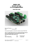
1
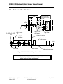
PMDX-170
Slotted Optical Sensor
User’s Manual
Document Revision: 1.0
Date: 20 May 2009
PMDX
9704-D Gunston Cove Rd
Lorton, VA 22079-2366 USA
PMDX-170_Manual_10.doc
20 May 2009
Web:
Phone:
FAX:
http://www.pmdx.com
+1 (703) 372-2975
+1 (703) 372-2977
©2009, Practical Micro Design, Inc.
All Rights Reserved
Page 1 of 8
PMDX-170 Slotted Optical Sensor User’s Manual
Document Revision: 1.0
Table of Contents
1.0
Overview.................................................................................................................................... 3
1.1
Important Safety Information ........................................................................................................................... 3
1.2
Warranty Summary............................................................................................................................................. 3
1.3
Features.................................................................................................................................................................. 4
1.4
Updates to this Manual ...................................................................................................................................... 4
2.0
Installation and Operation ...................................................................................................... 4
2.1
General Operating Constraints ....................................................................................................................... 4
2.2
Interruptor Design .............................................................................................................................................. 5
2.3
Output Signals ...................................................................................................................................................... 5
2.4
Mounting Options ............................................................................................................................................... 5
3.0
Mechanical Specifications........................................................................................................ 6
4.0
Electrical and Environmental Specifications ........................................................................ 7
Appendix A – Warranty...................................................................................................................... 8
PMDX-170_Manual_10.doc
20 May 2009
©2009, Practical Micro Design, Inc.
All Rights Reserved
Page 2 of 8
PMDX-170 Slotted Optical Sensor User’s Manual
Document Revision: 1.0
1.0
Overview
This document describes the configuration and operation of the PMDX-170 Slotted Optical Sensor. The
PMDX-170 Slotted Optical Sensor is useful for mill or lathe spindle speed sensing and for lathe threading
index position pickup, and for limit or home switches on machines where dust and debris are not a
problem.
1.1
Important Safety Information
The PMDX-170 Slotted Optical Sensor is intended for integration by the purchaser into industrial control
systems. It is solely the purchaser's responsibility to assure that the system is configured in a manner
consistent with applicable safety requirements. Practical Micro Design, Inc. does not control how these
parts are integrated into the purchaser's system and cannot be responsible for guaranteeing the safety of
your system.
The PMDX-170 Slotted Optical Sensor may be used for limit or home switch applications only if dust,
debris, coolants or cutting oils are not a problem.
The PMDX-170 Slotted Optical Sensor is not guaranteed to be fail-safe. The system into which the
PMDX-170 Slotted Optical Sensor are installed should provide fail-safe protection and emergency stop
capability.
Automated machine tools, into which the PMDX-170 Slotted Optical Sensor may be integrated, can cause
injury. Precautions should be taken to assure that operators are trained in their proper operation and
safety procedures, and that they are protected from moving parts that may be under remote control and
may move unexpectedly.
This product may not be used in life support or other critical safety applications.
1.2
Warranty Summary
The PMDX-170 Slotted Optical Sensor are warranted against failure due to defective parts or
workmanship for 90 days from the date of sale. Refer to Appendix A for complete warranty details.
NOTE: If you have an item requiring service, please see the support
page on the PMDX web site (http://www.pmdx.com) for
return instructions.
The purchaser must pay shipping to return the unit to PMDX. For repairs covered under warranty
shipped to a USA address we will ship the repaired unit back to you via ground transportation at our
expense. Repairs are normally completed within 10 business days. See Appendix A for our complete
warranty details. Please see the support page on our web site (http://www.pmdx.com) for full
details of our repair and shipping policies.
PMDX-170_Manual_10.doc
20 May 2009
©2009, Practical Micro Design, Inc.
All Rights Reserved
Page 3 of 8
PMDX-170 Slotted Optical Sensor User’s Manual
Document Revision: 1.0
1.3
Features
The PMDX-170 Slotted Optical Sensor has the following features:
•
Outputs are NPN "open collector" style
and provide either an open circuit or a path
to ground depending on state of sensor
•
Outputs work directly with PMDX
breakout board inputs and any other boards
that provide a "pull-up"
•
Sensor may be powered by any DC voltage
from 5 volts to 25 volts
•
Output voltage is independent of supply
voltage
LED indicator for sensor output status
•
•
Signals are conditioned by a Schmidt trigger
to avoid multiple false transitions
Response time of less than 10 microseconds
•
•
Both a True and a False output are
provided so user can select desired polarity
Mounting area of circuit board is free of
electrically conducting PCB traces
•
SMT component side is conformal coated
to help resist harsh environments
•
Optical interruption sensor for a disk with
holes or for a moving flag
•
Slot width of 3 mm with center of sensing
zone 2.5 mm below top of sensor
•
Small size 1.500" by 0.720" circuit board is
easy to mount using two screws
•
Two mounting orientations possible using
holes in circuit board or in sensor body
•
Easy to use clamp style screw terminal
strips for connections
•
1.4
Updates to this Manual
Check the PMDX web site for revisions or updates to this manual (http://www.pmdx.com). The latest
revision of this manual is available on the PMDX-170 Slotted Optical Sensor page (follow the links from
the main page).
2.0
Installation and Operation
These sensors are useful for mill or lathe spindle speed sensing and for lathe threading index position
pickup. While you may be able to use these sensors for limit or home switches they are recommended
for these applications only if dust, debris, coolants, or cutting oils are not a problem.
Note that all PMDX breakout boards have the necessary pull-up resistor on board and have power
available to run the sensor so no external components are needed.
Pin Label
V+
F
T
Gnd
Description
+5V to +25V DC power supply
False (inverted) output
(see section 2.3 for details)
True (non-inverted) output
(see section 2.3 for details)
Ground (power supply return)
Slot Open
(LED on)
N/A
pulled to GND
(logic low)
floats
(open-collector)
N/A
Slot Obstructed
(LED off)
N/A
floats
(open-collector)
pulled to GND
(logic low)
N/A
Table 1 –Connector Pin-Out & Output Polarity
2.1
General Operating Constraints
The maximum pulse rate using the PMDX-170 can be as high as 25 KHz if the optical path meets the
minimum on and off times. Your slot or hole should be sized according to the minimum on/off time and
the speed that it is moving. In practice, a 6mm hole in a 4 inch disk spinning at 40,000 RPM would work.
PMDX-170_Manual_10.doc
20 May 2009
©2009, Practical Micro Design, Inc.
All Rights Reserved
Page 4 of 8
PMDX-170 Slotted Optical Sensor User’s Manual
Document Revision: 1.0
Larger holes or wider slots result in lower effective pulse rates. Under all circumstances, the slot must be
fully blocked (or fully open) for a minimum of 20 µs at maximum speed in order for the sensor to output
a pulse. The exact width required for the interrupter depends on many factors, including the interface
electronics and control software. For example, a large-value pull-up resistor will slow the response time
of the sensor. All PMDX breakout boards have pull-up resistors that are compatible with this sensor.
For other applications or other breakout boards we recommend a 1.0K ohm pull-up when using a +5V
supply, or a 4.7K ohm pull-up when using a +24V supply. Finally, the time it takes the control software to
read the output of the sensor will limit the maximum pulse rate and minimum interrupter width. The
PMDX-170 is faster than most software sampling methods, so software performance will likely be the
limiting factor. The bottom line is that, in general, you should experiment with your setup to determine
the maximum operational limits.
2.2
Interruptor Design
Two types of interrupters can be used with the slotted optical sensor: a “flag” style, or a “solid with an
opening” style. The “flag “ style uses a small flag or tooth-shape protrusion to interrupt the LED/Sensor
path at the reference position. The “solid” style uses a solid interrupter that has an opening of some kind
at the reference position. When using a solid interrupter with an opening at the reference point, the
opening must extend a minimum of 2.5mm above and 2.5mm below the center line of the LED/Sensor
path (see Figure 1 on page 6). Therefore, if you are using a round hole, the hole must be 5mm diameter
or greater.
Warning:
2.3
The actual size of the interrupter opening depends on the speed of the
interrupter material and how short a pulse the PC can detect. The faster the
device is moving (and/or the slower the PC), the larger the hole needs to be in
order for the PC (or other hardware) to recognize the output pulse from the
sensor. You may have to experiment to determine the exact size opening that
your application requires.
Output Signals
The slotted sensor has two open-collector outputs labeled “T” and “F”, as shown in table 1 on page 4.
To obtain a valid logic level from a “floating” output, the output must have a resistor installed between
the output signal and a power supply voltage. Usually this is a resistor whose value is between 1.0K ohms
and 10K ohms, connected to a power supply between +5V to +25V VDC. See section 4.0 for
information on the maximum voltage that may be attached to the output signal.
Note that all PMDX breakout boards have the necessary pull-up resistor on board and have power
available to run the sensor so no external components are needed.
2.4
Mounting Options
The PMDX-170 can be mounted by two different methods. A mounting bracket can be attached to the
side of the sensor (see the “End View” in the mechanical drawing), or to the top side of the board (see
the “Top View” in the mechanical drawing). Do not put a mounting bracket on the bottom side of the
circuit board. If your machine requires that you mount the board from the bottom side you must use
1/4” (or taller) #4 (or 1/4” outer diameter) non-conductive spacers between the circuit board and the
bracket or panel.
The mounting holes in the sensor and the circuit board are sized for #4 hardware.
PMDX-170_Manual_10.doc
20 May 2009
©2009, Practical Micro Design, Inc.
All Rights Reserved
Page 5 of 8
PMDX-170 Slotted Optical Sensor User’s Manual
Document Revision: 1.0
3.0
Mechanical Specifications
1.500"
Mounting area clear
of elecrical circuits on
this side
0.800"
0.600"
Gnd
0.236"
T
0.236"
0.460"
F
0.236"
0.138" x 0.118"
slot
2 ea 0.115"
dia holes
Top View
Center line of slot
0.118"
dia hole
0.197"
+V
0.260"
Center line of
LED & sensor
0.720"
Center line of
LED & sensor
0.460"
0.361"
0.430"
0.062"
0.180"
0.236"
0.360"
0.236"
Side View
End View
Components on this side of
PCB, conformal coated.
Figure 1 - PMDX-170 Slotted Optical Sensor Dimensions
WARNING:
The PMDX-170 Slotted Optical Sensor should be protected from
liquids, dirt, or chips (especially metal chips which can cause
shorts) coming in contact with the board.
PMDX-170_Manual_10.doc
20 May 2009
©2009, Practical Micro Design, Inc.
All Rights Reserved
Page 6 of 8
PMDX-170 Slotted Optical Sensor User’s Manual
Document Revision: 1.0
4.0
Electrical and Environmental Specifications
Power Supply:
+5V to +25V VDC input, 25 mA maximum
Output:
Open-collector output
Max. output “low”:
0.4V sinking up to 6 mA
Max. output “high”:
pull-up resistor to 25V maximum
Pulse Rate:
in excess 25 KHz
10 µs response time turning “on” or “off”
NOTE: See also section 2.1 for more information.
Environmental:
Temperature:
Relative Humidity:
PMDX-170_Manual_10.doc
20 May 2009
0° to +55° C
20% to 80% relative humidity, non-condensing
©2009, Practical Micro Design, Inc.
All Rights Reserved
Page 7 of 8
PMDX-170 Slotted Optical Sensor User’s Manual
Document Revision: 1.0
Appendix A – Warranty
Statement
Practical Micro Design, Inc. (PMD) warrants that this hardware product is in good working
condition, according to its specifications at the time of shipment, for a period of 90 days
from the date it was shipped from PMD. Should the product, in PMD's opinion, malfunction
within the warranty period, PMD will repair or replace the product without charge. Any
replaced parts become the property of PMD. This warranty does not apply to the software
component of a product or to a product which has been damaged due to accident, misuse,
abuse, improper installation, usage not in accordance with product specifications and
instructions, natural or personal disaster or unauthorized alterations, repairs or
modifications.
Limitations
All warranties for this product, expressed or implied, are limited to 90 days from the date of
purchase and no warranties, expressed or implied, will apply after that period.
All warranties for this product, expressed or implied, shall extend only to the original
purchaser.
The liability of Practical Micro Design, Inc. in respect of any defective product will be limited
to the repair or replacement of such product. Practical Micro Design, Inc. may use new or
equivalent to new replacement parts.
Practical Micro Design, Inc. makes no other representations or warranties as to fitness for
purpose, merchantability or otherwise in respect of the product. No other representations,
warranties or conditions, shall be implied by statute or otherwise.
In no event shall Practical Micro Design, Inc. be responsible or liable for any damages arising
(a) from the use of the product;
(b) from the loss of use of the product;
(c) from the loss of revenue or profit resulting from the use of the product; or
(d) as a result of any event, circumstance, action or abuse beyond the control of Practical
Micro Design, Inc.
whether such damages be direct, indirect, consequential, special or otherwise and whether
such damages are incurred by the person to whom this warranty extends or a third party.
PMDX-170_Manual_10.doc
20 May 2009
©2009, Practical Micro Design, Inc.
All Rights Reserved
Page 8 of 8