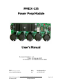
1
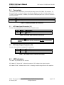
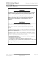
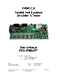
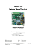
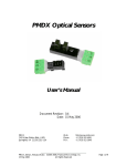
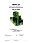
PMDX-135
Power Prep Module
User’s Manual
Document Revision: 1.2
Date: 20 February 2007
PCB Revision: PCB-456A and PCB-456B
PMDX
9704-D Gunston Cove Rd
Lorton, VA 22079-2366 USA
PMDX-135_Manual_12.doc
20 February 2007
Web:
Phone:
FAX:
http://www.pmdx.com
+1 (703) 372-2975
+1 (703) 372-2977
©2005-2007, Practical Micro Design, Inc.
All Rights Reserved
Page 1 of 8
PMDX-135 User’s Manual
PCB Revision: PCB-456A and PCB-456B
Document Revision: 1.2
Table of Contents
1.0
Overview.................................................................................................................................... 3
1.1
Ordering Information (part numbers) ........................................................................................................... 3
1.2
Important Safety Information ........................................................................................................................... 3
1.3
Warranty Summary............................................................................................................................................. 3
1.4
Features.................................................................................................................................................................. 4
1.5
Updates to this Manual ...................................................................................................................................... 4
2.0
Sample Input Wiring Diagram ............................................................................................... 4
3.0
Connectors ................................................................................................................................ 5
3.1
AC Power Input Connector (J1) ..................................................................................................................... 5
3.2
DC Power Output Connector (J2)................................................................................................................. 5
4.0
LED Indicators .......................................................................................................................... 5
5.0
Dump Circuit ............................................................................................................................ 6
6.0
Voltage and Transformer Selection ...................................................................................... 6
6.1
Selecting AC Input and DC Output Voltages .............................................................................................. 6
6.2
Selecting Transformer Current Rating........................................................................................................... 6
7.0
Mechanical Specifications........................................................................................................ 7
8.0
Electrical and Environmental Specifications ........................................................................ 7
Appendix A – Warranty...................................................................................................................... 8
PMDX-135_Manual_12.doc
20 February 2007
©2005-2007, Practical Micro Design, Inc.
All Rights Reserved
Page 2 of 8
PMDX-135 User’s Manual
PCB Revision: PCB-456A and PCB-456B
Document Revision: 1.2
1.0
Overview
This document describes the configuration and operation of the PMDX-135 Power Prep Module. This
document pertains to the following versions of the PMDX-135:
Circuit Board Revision:
1.1
PCB-456A and PCB-456B (marked on the bottom of the board)
Ordering Information (part numbers)
The PMDX-135 can be built to support various output voltage and current requirements, as designated by
the full part numbers:
Part Number
PMDX-135-8020
PMDX-135-5020
Output Capacity
80 VDC, up to 20 Amperes
50 VDC, up to 20 Amperes
For lower voltage applications, the PMDX-135-5020 is preferred over the PMDX-135-8020 because the
PMDX-135-5020 offers greater filter capacitance.
The appearance and number of filter capacitors can vary between the different PMDX-135 models, as well
as among boards of the same model due to different vendors of filter caps.
1.2
Important Safety Information
The PMDX-135 is intended for integration by the purchaser into industrial control systems. It is solely
the purchaser's responsibility to assure that the system is configured in a manner consistent with
applicable safety requirements. Practical Micro Design, Inc. does not control how this board is integrated
into the purchaser's system and cannot be responsible for guaranteeing the safety of your system.
The PMDX-135 is not guaranteed to be fail-safe. The system into which the PMDX-135 is installed should
provide fail-safe protection and emergency stop capability.
The PMDX-135 contains circuitry that may be connected to dangerous voltages. Care must be taken that
user cannot come in contact with these voltages. An enclosure that allows for adequate ventilation, but
prevents intrusion by operator’s hands and foreign objects, especially conductive byproducts of machining
operations, should be utilized with this board. Interlock switches on power circuits should remove
power when the enclosure is opened.
Automated machine tools, into which the PMDX-135 may be integrated, can cause injury. Precautions
should be taken to assure that operators are trained in their proper operation and safety procedures, and
that they are protected from moving parts that may be under remote control and may move
unexpectedly.
This product may not be used in life support or other critical safety applications.
1.3
Warranty Summary
The PMDX-135 is warranted against failure due to defective parts or workmanship for 90 days from the
date of sale. Refer to Appendix A for complete warranty details.
If you have an item requiring service, please see the support page on the PMDX web site
(http://www.pmdx.com) for return instructions.
The purchaser must pay shipping to return the unit to PMDX. We will ship the repaired unit back to you
via ground transportation at our expense. Repairs are normally completed within 10 business days. See
Appendix A for our complete warranty details.
PMDX-135_Manual_12.doc
20 February 2007
©2005-2007, Practical Micro Design, Inc.
All Rights Reserved
Page 3 of 8
PMDX-135 User’s Manual
PCB Revision: PCB-456A and PCB-456B
Document Revision: 1.2
1.4
Features
The PMDX-135 has the following features:
Designed for True 20 Amp Performance:
• Multiple filter capacitors to reduce heating
caused by high ripple current
DC Output Power:
• 24 to 80 volts DC for the PMDX-135-8020
•
Heatsink on bridge rectifier
•
Extra large copper areas on PCB in highcurrent areas.
• Both versions support up to 20 Amperes
Dump Circuit:
• Electronic “back EMF” dump circuit to shunt
excess power returned by motors to help
prevent over-voltage on the DC output.
AC Input Power:
• 18 to 56 volts AC for the PMDX-135-8020
•
18 to 36 volts AC for the PMDX-135-5020
1.5
•
•
24 to 50 volts DC for the PMDX-135-5020
Rapid discharge circuit to remove charge
from filter capacitors within 5 seconds or
removal of input power.
Updates to this Manual
Check the PMDX web site for revisions or updates to this manual (http://www.pmdx.com). The latest
revision of this manual is available on the PMDX-135 page (follow the links from the main page).
2.0
Sample Input Wiring Diagram
Double-pole
Power Switch
In-rush
current limiter
(optional)
E-Stop Switch
or Relay
Power
Transformer
To PMDX-135
AC Input
Figure 1 – Sample input wiring diagram
WARNING:
The AC input must be transformer-isolated from the mains input. Autotransformers and variable (Variac) transformers DO NOT provide suitable
isolation.
PMDX-135_Manual_12.doc
20 February 2007
©2005-2007, Practical Micro Design, Inc.
All Rights Reserved
Page 4 of 8
PMDX-135 User’s Manual
PCB Revision: PCB-456A and PCB-456B
Document Revision: 1.2
3.0
Connectors
The following sections describe the pin-out and functionality of each of the PMDX-135 connectors. For
all connectors, pin “1” is the pin closest to the reference designator (i.e. J1 pin 1 is the pin closest to the
“J1” text on the circuit board). In addition, all connectors have square pads on pin 1 (look on the bottom
of the circuit board).
Connector
J1
J2
Description
AC Power Input
DC Power Output
Table 1 - Summary of PMDX-135 Connectors
3.1
AC Power Input Connector (J1)
Connector J1 provides alternate connections for the input AC power.
Pin
1
2
Label
none
none
Description
AC input
AC input
Table 2 –AC Power Input Connector Pin-Out (J1)
WARNING:
3.2
The AC input must be transformer-isolated from the mains input. Autotransformers and variable (Variac) transformers DO NOT provide suitable
isolation.
DC Power Output Connector (J2)
Connector J2 provides the unregulated DC output power.
Pin
1
2
Label
POS
NEG
Description
Positive DC output
Negative DC output
Table 3 – DC Ouput Power Connector Pin-Out (J2)
4.0
LED Indicators
The PMDX-135 provides two LED indicators.
DS1, labeled “DC Output ON”, indicates the presence of DC voltage on the output connector.
DS2, labeled “DUMP”, indicates that the circuit is “dumping” excessive charge from the filter capacitors.
PMDX-135_Manual_12.doc
20 February 2007
©2005-2007, Practical Micro Design, Inc.
All Rights Reserved
Page 5 of 8
PMDX-135 User’s Manual
PCB Revision: PCB-456A and PCB-456B
Document Revision: 1.2
5.0
Dump Circuit
The dump circuit works by placing a heavy resistor load on the DC output whenever the output rises
above the internally-generated voltage. This helps prevent damage to motor drivers when the back EMF
from decelerating motors causes current to flow back into the power supply and thereby trying to raise
the output voltage. When the PMDX-135 senses this voltage surge, the resistive load is applied to help
absorb the excess voltage. The “DUMP” LED indicates when this is occurring.
The dump circuit resistors are intended for short bursts of operation. If the dump circuit is active more
than 10% of the time the resistors may overheat.
The dump circuit also acts to rapidly discharge the main filter capacitors when the input power is
removed.
6.0
Voltage and Transformer Selection
There are several factors to consider when choosing input and output voltages for the PMDX-135, as
described in the following sections.
6.1
Selecting AC Input and DC Output Voltages
The PMDX-135’s output voltage is specified by the following equation:
DC output voltage = [ (AC input voltage) * 1.414 ] – 1.5 volts
For example, 48 volts AC input yields 66.37 volts DC on the output.
Input voltage should be selected to allow some safety margin in the output voltage. Some transformer
output voltages may be several percent higher than specified by the manufacturer when lightly loaded.
This property is sometimes specified as “percent regulation” by the transformer manufactures. Toroid
transformers typically have better regulation than conventional transformers. Additionally, the AC mains
voltages can often be 10% higher than nominal. Therefore, use the following equation to calculate the
worst-case output voltage:
[ (high line) * (regulation factor) * (nominal voltage * 1.414) ] – 1.5V
In this case, our 48 volt transformer could yield a worst-case output voltage of:
[ (110%) * (108%) * (48 * 1.414) ] – 1.5 which equals 79.13 volts DC
For this reason, if you intend to power Geckodrive products near their rated input voltage (80V DC),
PMDX recommends that the supply be limited to transformers that will not cause greater than 80V DC
output when all factors are worst case.
6.2
Selecting Transformer Current Rating
Transformers are most often rated in RMS output current. The input of a bridge rectifier/capacitor filter
power supply is not an RMS load. Indeed, it has a much worse load factor. Conservative design
recommendations for transformer manufactures may specify that the transformer be RMS rated for as
much as 1.8 times the DC output current of the bridge rectifier/capacitor filter power supply.
One exception to this may be transformers that are specified for “rectifier duty”.
PMDX-135_Manual_12.doc
20 February 2007
©2005-2007, Practical Micro Design, Inc.
All Rights Reserved
Page 6 of 8
PMDX-135 User’s Manual
PCB Revision: PCB-456A and PCB-456B
Document Revision: 1.2
7.0
Mechanical Specifications
8.000"
J1
3.050"
NEG
24 to 80
VDC
POS
J2
0.150"
4 each 0.150" dia holes
(for #6 screw)
7.850"
0.150"
Figure 2 - PMDX-135 Dimensions and Mounting Holes
The maximum clearance height above the PMDX-135 circuit board is 2.175 inches, and beneath the
circuit board is 0.125 inches.
WARNING:
8.0
The PMDX-135 should be protected from liquids, dirt, or chips
(especially metal chips which can cause shorts) coming in contact
with the board.
Electrical and Environmental Specifications
Power:
Power In:
Power Out:
Dump Circuit
Duty Cycle:
Environmental:
WARNING:
PMDX-135-8020 – 18 to 56 volts AC
PMDX-135-5020 – 18 to 36 volts AC
(note that the exact input voltage depends on your desired DC output voltage)
PMDX-135-8020 – 24 to 80 volts DC, unregulated with a minimum of 23,500 µF filter
PMDX-135-5020 – 24 to 50 volts DC, unregulated with a minimum of 48,000 µF filter
(note that the exact output voltage depends on AC input voltage)
10% maximum
Temperature:
Relative Humidity:
0° to +55° C
20% to 80% relative humidity, non-condensing
Forced-air cooling is required for operation in ambient temperatures above
40° C, and is recommended for operation above 30° C or when drawing
near full load.
PMDX-135_Manual_12.doc
20 February 2007
©2005-2007, Practical Micro Design, Inc.
All Rights Reserved
Page 7 of 8
3.200"
18 to 56
VOLTS
AC Input
PMDX-135 User’s Manual
PCB Revision: PCB-456A and PCB-456B
Document Revision: 1.2
Appendix A – Warranty
Statement
Practical Micro Design, Inc. (PMD) warrants that this hardware product is in good working
condition, according to its specifications at the time of shipment, for a period of 90 days
from the date it was shipped from PMD. Should the product, in PMD's opinion, malfunction
within the warranty period, PMD will repair or replace the product without charge. Any
replaced parts become the property of PMD. This warranty does not apply to the software
component of a product or to a product which has been damaged due to accident, misuse,
abuse, improper installation, usage not in accordance with product specifications and
instructions, natural or personal disaster or unauthorized alterations, repairs or
modifications.
Limitations
All warranties for this product, expressed or implied, are limited to 90 days from the date of
purchase and no warranties, expressed or implied, will apply after that period.
All warranties for this product, expressed or implied, shall extend only to the original
purchaser.
The liability of Practical Micro Design, Inc. in respect of any defective product will be limited
to the repair or replacement of such product. Practical Micro Design, Inc. may use new or
equivalent to new replacement parts.
Practical Micro Design, Inc. makes no other representations or warranties as to fitness for
purpose, merchantability or otherwise in respect of the product. No other representations,
warranties or conditions, shall be implied by statute or otherwise.
In no event shall Practical Micro Design, Inc. be responsible or liable for any damages arising
(a) from the use of the product;
(b) from the loss of use of the product;
(c) from the loss of revenue or profit resulting from the use of the product; or
(d) as a result of any event, circumstance, action or abuse beyond the control of Practical
Micro Design, Inc.
whether such damages be direct, indirect, consequential, special or otherwise and whether
such damages are incurred by the person to whom this warranty extends or a third party.
PMDX-135_Manual_12.doc
20 February 2007
©2005-2007, Practical Micro Design, Inc.
All Rights Reserved
Page 8 of 8