1
PI5600 PAYOUT INDICATOR
USER'S MANUAL
Revision 3
March 15, 2002
Subsea Systems, Inc.
2290 Eastman Avenue, Suite 111
Ventura, CA 93003
(805) 658-8388
Fax: (805) 658-8424
www.subsea-usa.com
Copyright 1996, Subsea Systems, Inc.
The material contained herein is the property of Subsea Systems, Inc.
and may not be reproduced without written consent.
TABLE OF CONTENTS
SECTION 1: GENERAL INFORMATION .......................................................................1
INTRODUCTION.....................................................................................................1
GENERAL DESCRIPTION ...................................................................................1
FEATURES ..............................................................................................................1
SPECIFICATIONS ..................................................................................................2
SECTION 2: HARDWARE PREPARATION AND INSTALLATION............................3
INTRODUCTION.....................................................................................................3
UNPACKING INSTRUCTIONS .............................................................................3
INSTALLATION INSTRUCTIONS ........................................................................4
CHECKOUT PROCEDURE...................................................................................5
SECTION 3: OPERATING INSTRUCTIONS..................................................................7
INTRODUCTION.....................................................................................................7
KEYPAD CONTROL DESCRIPTION ..................................................................8
LIMITATIONS...........................................................................................................8
OPERATING PROCEDURES...............................................................................8
GENERAL.................................................................................................................8
RESET ......................................................................................................................8
MUTE ........................................................................................................................9
UNIT CONVERSION...............................................................................................9
MAGNET-SPACING ...............................................................................................9
MINIMUM COUNT ALARM....................................................................................9
MAXIMUM ALARM COUNT ..................................................................................10
DISPLAY EEPROM CONTENTS .........................................................................10
PRESET COUNT.....................................................................................................10
SECTION 4: TROUBLESHOOTING ................................................................................11
SHEAVE ROTATION CAUSES ERRORS ..........................................................11
NO AC POWER TO PI5600 ..................................................................................12
LOW BATTERY CHARGE .....................................................................................12
MONITOR OUTPUT GARBLED OR NONEXISTENT ......................................13
SHEAVE JITTER CAUSES COUNTING.............................................................13
SHEAVE COUNT POLARITY REVERSED........................................................14
SECTION 5: SOFTWARE ERRATA ................................................................................15
SECTION 6: SCHEMATICS ..............................................................................................17
SECTION 1: GENERAL INFORMATION
INTRODUCTION
This manual provides general information, hardware description, installation
instructions, operating instructions, and support information for the PI5600.
GENERAL DESCRIPTION
The PI5600 is an automated, portable device used in conjunction with a cable
tow reel and a sheave with magnets implanted around its periphery. The unit
measures outgoing and incoming cable length to a resolution of +.001 ft, up to a
maximum of +65,501.233 ft or +19,977.876 meters, (for a magnet-spacing of 1.999
feet).
The unit is environmentally sealed and its corrosion-resistant fabrication
makes it the ideal instrument for harsh environments and oceanographic
applications requiring an accurate reading of the amount of cable towed behind a
vessel.
FEATURES:
Monitors cable deployment and recovery
Provides measurements in feet or meters, and automatically converts
between them
Measures up to +65,501.233 feet or +19,977.876 meters,
depending upon magnet-spacing
Stainless steel, gasketed construction is environmentally
sealed and corrosion-resistant
Incorporates backlight in LCD for low-light viewing
Eliminates the need for any operator calculations
Generates audible alarms when user-specified maximum
minimum payout setpoints are exceeded
Allows the user to program maximum alarm, minimum alarm,
and preset values
Stores alarm and magnet-spacing values in non-volatile EEPROM
Uses CMOS circuitry for low power consumption and high noise
immunity
Operates from an internal NiCd battery during AC power loss
Supports RS-232C communications
Uses input from either a Geoquip or Sea-Mac sheave sensor
Allows operator to reverse rotational sense without moving sheave,
when using a Geoquip sensor
1
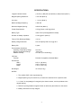
SPECIFICATIONS:
Largest Indicated Values:
(+32,767) x (MS) feet (+9,993.935) x (MS) meters (Note 1)
Magnet-Spacing Resolution:
+.001 feet (Note 2)
Accuracy:
+ 1 count (Note 3)
Maximum Magnet-Spacing:
1.999 feet
Minimum Magnet-Spacing:
0.0833 feet (Note 4)
Power Requirements:
115V @ 70mA or 230V @ 35mA
Battery Type:
Varta TR7/8 (Rechargeable 9V NiCad)
Duration of Battery Operation:
10 min @ 30°C (Note 5)
Time to Fully Recharge Battery:
>14 hrs
Battery Charge Retention:
50% of Capacity After 3 mos @ 30°C
Battery Life:
2 years
Environmental Conditions:
Operating Temperature Range
Storage Temperature Range
Relative Humidity
0 to 45°C
-40 to 50°C
0 to 90% (non-condensing)
I/O Ports:
Terminal
RS-232C Compatible, 300-9600 Baud
Dimensions:
Width
Length
Depth
8.00 in. (20.32cm)
9.94 in. (25.24 cm)
4.75 in. (12.07 cm)
Net Weight:
12.3 lbs (5.6 kg)
NOTES:
1. The variable "MS" is the magnet-spacing.
2. Magnet-spacing may be entered only in feet and is assumed to be a positive value.
3. A "count" is one passage of a magnet by the sheave sensor, and is equivalent to the
magnet spacing.
4. Refers to spacing between magnetic fields, as defined by their effects on the sensor.
5. Battery assumed to be fully charged.
2
SECTION 2: HARDWARE PREPARATION AND INSTALLATION
INTRODUCTION
This section provides unpacking instructions, installation instructions and a
checkout procedure.
UNPACKING INSTRUCTIONS
Unpack the unit from the shipping container. Refer to the packing list and
verify that all items are present. Save the packing material for storing or reshipping
of the Unit.
NOTE: If the shipping carton is damaged upon receipt, request the carrier's
agent to be present during unpacking and inspection of the PI5600.
INSTALLATION INSTRUCTIONS
1. Location of Unit:
Adequate consideration of the orientation of the PI5600 is mandatory to
insure the greatest display contrast and viewing clarity.
The Unit is secured via the four mounting holes in the case to either a vertical
or a horizontal mounting surface. It may be mounted either at the winch or at some
remote location.
2. Adjusting LCD Contrast:
NOTE: This procedure must be performed in a clean, dry environment,
preferably indoors, to avoid electrical shock.
2.1 Loosen clamps, open case lid, and locate trimpot R5(slightly above the
middle of the left edge of the CPU printed circuit board, as the unit is viewed
with the lid opened to the left).
2.2 Close lid, turn on power, and note current LCD contrast. Be careful to
avoid any exposed terminals carrying ACpower, especially on the PowerSupply board.
2.3 Turn off power, open lid, and adjust R5.
2.4 Repeat Steps 2.2 & 2.3 until desired contrast is achieved.
2.5 Turn off power and re-fasten clamps.
3
3. Power Supply Connections:
A connector is provided for power and mates with the Unit's connector labeled
"Power" J1. The unit is shipped with jumper settings on the Power Supply board to
accommodate 115V AC @ 70 mA. However, the PI5600 may be reconfigured to
accept 230V AC @ 35mA by removing the two "115V" jumpers from the Power
Supply board and relocating them into the "230V" holes.
NOTE: Since shipboard power is susceptible to fluctuations and surge, it is
strongly recommended that the line voltage be measured prior to applying power to
the unit.
4. Remote Sensor Location:
The sheave may be mounted at any convenient location at the stern of the
ship. The sensor is mounted to the sheave. Note that the sensor must be located
on the side of the sheave bearing the magnets. Also, Geoquip Sensors should be
oriented such that the engraved arrows point toward the sheave wheel. (See DWG#
049-1-004.) The one-hundred-foot sensor cable provided mates with a Geoquip
Sensor and the "Sensor" J2 connector on the PI5600.
5. Terminal Computer I/O Connections:
The optional terminal I/O connector ("Serial Port" J3) may be used to display
the PI5600's count to an external computer terminal. Connect an RS-232Ccompatible cable to the mating female connector labeled on the Unit. When properly
connected, the "SUBSEA " logo will be displayed on the external terminal or
computer.
NOTE: The factory-set baud rate is 9600 baud, 7 data bits, no parity, and
one stop bit.
6. Normal Mode vs. Sea-Mac Mode:
6.1 General Considerations:
Units with "56CX", "56D", or later CPU boards accept input from either SeaMac or Geoquip Sensors, and these units do not require any special configuration.
In addition, these units allow the operator to use SW2 on the CPU board to reverse
the sheave rotational polarity for either type of sensor.
4
CHECKOUT PROCEDURE
This procedure assumes that the PI5600 has been installed properly, and enables
the user to verify basic operation of the PI5600.
1. Measuring Magnet-Spacing:
Before installing the sheave, use a rope of approximately the same diameter
as the intended cable to determine sheave circumference in units of feet. Divide the
circumference by the number of magnets implanted in the sheave, to obtain the
magnet-spacing. Round the magnet-spacing to three decimal places. If possible,
keep the sheave near at hand for purposes of this checkout procedure.
2. Power:
Turn the PI5600 power switch on, and verify that the display shows
"+00000.000 FEET" or "+00000.000 METERS", and that the backlight in the LCD
illuminates. If the PI5600 fails to perform one or both of these functions, see the
"Troubleshooting" section.
Also refer to the "Troubleshooting" section if the PI5600 emits beeps and/or
alternates the length-unit designation (i.e. "FEET" or "METERS") with the message
"AC OFF" or "LO BAT".
3. RS-232C:
If the optional RS-232C cable is installed between a terminal and J3 of the
PI5600, verify that the following data appears on the monitor screen when the
PI5600 power is switched on:
A) The Subsea logo appears in the middle of the screen.
B) Data output (including payout polarity, measurement, and units) appears
on the bottom line of the screen.
Note that only the data-line is re-transmitted regularly, such that the logo will
appear only after the PI5600 is powered-up or reset with the RS-232C terminal
already on. If the monitor display is incorrect or nonexistent, see the
"Troubleshooting" section.
4. Programming:
Put the PI5600 into the "FEET" mode, and program the proper magnetspacing and minimum and maximum alarm setpoints, as described in the Operating
Instructions below. Use the "Display" functions to verify that these settings have
been modified correctly.
5
5. Sheave Count Polarity:
The PI5600 is intended to show increasingly positive or decreasingly negative
values as cable is paid out, and increasingly negative or decreasingly positive values
as cable is hauled in.
If the sheave is available and properly attached to PI5600 connector J2, try
turning the sheave one full rotation in the direction corresponding to outgoing cable.
Verify that the display shows a "+" with the sheave's circumference. If the
magnitude is incorrect, refer to "Troubleshooting". If the magnitude of the
circumference is correct but the displayed sign is "-", then the sheave count polarity
must be reversed. SW2 may be used to reverse sheave count polarity as follows:
Turn the power off, loosen the lid clamps, and open the lid.
Reverse the position of SW2 ("Direction"), in the lower, right-hand corner of
the CPU printed circuit board, and close up the box again.
Turn the power back on, and repeat the sheave polarity test above to verify
that the count polarity is now positive in the outgoing direction. Note that failing
to correct a reversed sheave count polarity invalidates alarm settings, since alarms
are only triggered for positive counts.
6
SECTION 3: OPERATING INSTRUCTIONS
INTRODUCTION
This section provides the necessary information to initialize and operate the PI5600.
Information consists of the keypad control description, operating limitations, and
operating procedures.
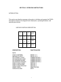
KEYPAD CONTROL DESCRIPTION
1
2
3
MUTE
4
5
6
DISPLAY
7
8
9
RESET
.
0
#
ENTER
DESCRIPTION
FUNCTION KEYS
MUTE
FEET TO METERS
METERS TO FEET
SET PRESET COUNT
SET MAXIMUM ALARM
SET MINIMUM ALARM
SET MAGNET-SPACING
DISPLAY MAX ALARM
DISPLAY MIN ALARM
DISPLAY MAG-SPACING
RESET PI5600
SILENCE ALARM
ENTER - # -1
ENTER - # -2
NUMBER-ENTER-1
NUMBER-ENTER-2
NUMBER-ENTER-3
NUMBER-ENTER-4
DISPLAY-2
DISPLAY-3
DISPLAY-4
RESET-ENTER
MUTE
7
LIMITATIONS
The Unit's RS-232C I/O port is factory set for 9600 baud. This baud rate may be
changed at the jumper header next to IC10. Note that the number of data bits,
polarity, and the number of stop bits cannot be modified.
The Unit trades off resolution for capacity at larger magnet-spacings, and vice-versa
at smaller magnet-spacings. Specifically:
Max Indicated Feet = (+32,767) x (magnet-spacing) feet
Max Indicated Meters = (+9,993.935) x (magnet-spacing) meters
After the user enters a preset value, the PI5600 enters a short period where it
remains unresponsive to further input, and does not update the display. The
duration of this period is directly proportional to the magnitude of the preset value.
For example, a preset value between 20,000-30,000 results in a delay between 90115 seconds, for a magnet-spacing of 0.833 feet. Smaller
magnet-spacings cause longer delays, for a given preset value.If at any time a
malfunction should occur, turning the power switch off and on should reset the
system.
When the maximum positive payout indication is exceeded, the count rolls-over to
the maximum negative indication, and becomes decreasingly negative. The
converse is also true: exceeding the maximum negative value forces a roll-over to
the maximum positive value.
OPERATING PROCEDURES
GENERAL:
Most of the functions above can be terminated in the middle of a key sequence by
pressing "ENTER" twice, to obtain a "USER INPUT ERROR" message. The main
exception is Reset, which is terminated by pressing any key except "ENTER" after
pressing "RESET".
RESET:
During normal operations, if the operator desires to set the display to indicate all
zeroes, pressing the key labeled "RESET"causes the display to prompt:
PRESS ENTER TO RESET
Pressing the "ENTER" key will reset the system and display all zeroes. Pressing
any other key will cancel the Reset operation.
8
MUTE:
Pressing this key silences an audible alarm. The audible alarm sounds when the
display count exceeds the maximum alarm count or drops below the minimum alarm
count.
UNIT CONVERSION:
These two commands allow the operator to convert both the current count and the
counting mode from "feet" to "meters" or vice-versa:
FEET TO METERS: ENTER-#-1
METERS TO FEET: ENTER-#-2
MAGNET-SPACING:
The magnet-spacing must be entered in feet with a 3-digit decimal point. The entry
is then stored permanently in EEPROM to be viewed or modified by the user. The
following key sequence stores the magnet-spacing:
STORE MAG. SPACING: NUMBER-ENTER-4
"NUMBER" is in the form "X.XXX", where X = a digit from 0 to 9. No leading zeroes
are accepted. Padding zeroes must be added to 3 digits; e.g. "1.300". Entering
more than 3 digits after the decimal point causes an "OVERFLOW" message.
Entering more than 6 digits with a decimal point causes the PI5600 to terminate the
"Store Magnet-Spacing" operation, without any changes.
MINIMUM COUNT ALARM:
A minimum count comparison function sounds an audible alarm when the amount of
cable out drops below the positive value preset by the operator. The minimum count
value is stored in EEPROM, and may be viewed or modified by the user. The
following key sequence stores the minimum count:
MINIMUM COUNT ALARM: NUMBER-ENTER-3
"NUMBER" is in the form "XXXXX", where X = a digit from 0 to 9. No leading zeroes
are accepted. Entering more than 5 digits causes an "OVERFLOW" message.
Entering numbers between 65536 and 99999 causes counter wrap-around; i.e.
65536 = 1, etc. Decimal numbers will be truncated to integers. Length units are
assumed to be feet.
9
MAXIMUM ALARM COUNT:
A maximum count comparison function sounds an audible alarm when the amount of
cable out exceeds the positive value preset by the operator. The maximum count
value is stored in EEPROM, and may be viewed or modified by the user. The
following key sequence stores the maximum count:
MAXIMUM COUNT ALARM: NUMBER-ENTER-2
"NUMBER" is in the form "XXXXX", where X = a digit from 0 to 9. No leading zeroes
are accepted. Entering more than 5 digits causes an "OVERFLOW" message.
Entering numbers between 65536 and 99999 causes counter wrap-around; i.e.
65536 = 1, etc. Decimal numbers will be truncated to integers. Length units are
assumed to be feet.
DISPLAY EEPROM CONTENTS:
To view the magnet-spacing or an alarm setting, press one of the following:
DISPLAY MAXIMUM ALARM: DISPLAY-2
DISPLAY MINIMUM ALARM: DISPLAY-3
DISPLAY MAG. SPACING: DISPLAY-4
PRESET COUNT:
To preset a count press the following:
PRESET COUNT: NUMBER-ENTER-1
"NUMBER" consists of up to 6 digits and a decimal point for decimal numbers, or up
to 5 digits for an integer, where:
1) Decimal numbers may have from 1 to 3 digits to the right of the decimal.
2) Entering numbers which exceed the maximum indicated value
(for the current magnet-spacing) gives unpredictable results, and should be avoided.
3) Negative presets cannot be entered.
4) Length units are assumed to be feet.
Note: The larger the preset value, the longer the delay before the PI5600 can begin
operation after a preset. For example, presetting to a value of 20,000 ft locks up the
PI5600 for about 90 sec, for a magnet-spacing of 0.833 ft. Smaller magnet-spacings
cause longer delays, for a given preset value.
10
SECTION 4: TROUBLESHOOTING
1. SHEAVE ROTATION CAUSES ERRORS:
1.1 Symptoms:
a.
Each magnet-pass or turn of the sheave causes the PI5600 to display
changes in length which are incorrect, whether or not the correct
magnet-spacing has been programmed into the Unit.
1.2 Probable Causes:
a.
Brand new MCU installed: The EEPROM storage for the magnetspacing parameter is located inside the MCU chip (68HC11A1). A new
chip will contain indeterminate data in the memory locations for
magnet-spacing, minimum alarm and maximum alarm.
NOTE: Do not attempt replace 68HC11AN MCU with a newer
68HC11EN MCU. The EPROM program must also be changed.
b.
EEPROM corrupted: Strong power surges and/or static electrical
ischarges inside the box may be able to corrupt the magnet-spacing,
minimum alarm and maximum alarm data.
1.3 Solutions:
a.
Turn power on.
b.
Put PI5600 into "Feet" mode (Enter + # + 2).
c.
Program magnet-spacing, minimum alarm, and maximum alarm into
PI5600. Remember that all three parameters are in feet.
d.
Push the "Reset" button on the keyboard, and then push "Enter".
e.
Use the "Display" functions to verify that desired parameters have
been stored.
f.
You may now operate the PI5600 in either the "Feet" or "Meters"
mode.
2. NO AC POWER TO PI5600
2.1 Symptoms:
a.
When power is switched on, LCD shows nothing, or displays
characters, but backlight remains unlit.
11
b.
If characters are displayed, length-unit designation (i.e. "FEET" or
"METERS") alternates with the message "AC OFF".
2.2 Probable Causes:
a.
Power cord (to J1) unplugged at one or both ends.
b.
Power cord has one or more broken conductors or connector pins.
c.
Fuse is blown. (Fuse is 0.25A, 250V, and is located on power supply
board.)
2.3 Solutions: Self-explanatory.
3. LOW BATTERY CHARGE:
3.1 Symptoms:
a.
When power is switched on, length-unit designation (i.e. "FEET" or
"METERS") alternates with the message "LO BAT".
b.
When power cord is disconnected with PI5600 still activated, LCD
characters either fade out, or "LO BAT" message alternates with
length-unit designation.
3.2 Probable Cause:
a.
Battery is discharged or defective.
3.3 Solution:
a.
Leave power cord attached to PI5600, and leave power switch on, for
about 24 hrs., to allow battery to charge.
b.
If "LO BAT" message persists, and/or characters fade from
LCD when power cord is unplugged, replace battery.
4. MONITOR OUTPUT GARBLED OR NONEXISTENT:
4.1 Symptoms:
a.
Data displayed on a monitor connected to J3 of PI5600, via optional
cable, appears garbled or does not appear.
12
4.2 Probable Causes:
a.
Mismatches exist between the monitor and the PI5600 settings
for baud rate, number of data bits, parity, and/or number of stop bits.
b.
RS-232C cable is unplugged at one or both ends.
c.
RS-232C cable has one or more broken conductors or connector pins.
d.
Transmit and receive lines in RS-232C cable need to be reversed.
4.3 Solutions:
a.
Mismatches:
1)
Baud Rate: Factory-set to 9600 baud, but may be adjusted on
jumper header next to IC10 on CPU PC board. Baud rates
available are silk-screened next to corresponding jumper pins.
2)
Data Bits: 7, unchangeable
3)
Parity: none, unchangeable
4)
Stop Bits: 1, unchangeable
b.
RS-232 Cord Loose or Broken: Check, tighten, and/or repair.
c.
Transmit/Receive Line Reversal:
1)
The PI5600 transmits data on pin 3 of the DB-25 and the DE-9.
2)
Determine whether the monitor receives its data on pin 2 or pin
3, and swap these pins in the DB-25 or DE-9 if necessary.
5. SHEAVE JITTER CAUSES COUNTING:
5.1 Symptoms:
a.
Boat motion relative to towfish causes sheave to rock a magnet back
and forth across the sensor, such that the payout indicator shows a net
increase or decrease.
5.2 Probable Causes:
a.
CPU board in Unit is "56B" or "56C".
b.
SW1 ("Filter") in lower, right-hand corner of CPU PCB is "In".
13
5.3 Solutions:
a.
Reposition sheave wheel such that no magnets are directly above the
sensor box.
b.
Change SW1 to "Out".
c.
Obtain upgrade to "56CX" CPU board.
6. SHEAVE COUNT POLARITY REVERSED:
6.1 Symptoms:
a.
Outgoing cable causes increasingly negative or decreasingly positive
values to be displayed.
b.
Incoming cable causes increasingly positive or decreasingly negative
values to be displayed.
6.2 Probable Causes:
a.
Sheave is reverse-mounted.
6.3 Solution:
a.
Follow instructions in "Checkout Procedure", Step 5.
14
SECTION 5: SOFTWARE ERRATA
Version: 1.0
Date: 3-8-90
1) Maximum and minimum alarms can be set to values exceeding the maximum
indicated value for a given magnet-spacing (e.g. 32,767 feet for MS = 1.000 ft).
However, the PI5600 will not measure payouts above this maximum. Thus, alarm
setpoints above the maximum indicated value and below 65,536 feet will never be
triggered. The PI5600 appears to accept alarm setpoints of 65,536 to 99,999 feet,
but in fact the Unit "rolls-over" these setpoints. Specifically, attempting to set the
max alarm to 65,536 feet actually sets it to 1 foot, while 65,537 feet rolls over to 2
feet, etc. Attempting to enter 100,000 feet or more results in an overflow error
message and termination of alarm setpoint entry.
2) The "INPUT OVERFLOW" error message is actually displayed as
"INPUOVERFLOW".
3) Although the PI5600 will accept magnet-spacings greater than 1.999 ft, its
behavior at indicated values greater than 32,767 ft is unpredictable. Unusual
behavior includes periodic beeping and nonsense indicated values. Avoid using
magnet-spacings greater than 1.999 ft.
4) Attempting to preset the PI5600 to a value greater than the maximum indicated
value for the current magnet-spacing yields unpredictable results. The displayed
value may have rolled-over through either the positive or negative maximum value,
or the system may lock up and emit a continuous buzzing tone. Do not try to preset
to a value greater than the current maximum indicated value.
5) The Preset function is intended to preset the PI5600 counters to the number of
counts corresponding to the payout length closest to the length desired by the user.
However, the Preset function usually errs by +1 magnet-spacing. For example, for a
magnet-spacing of .833 and a preset of 1000, the correct preset would be either
999.600 or 1000.433. The actual preset value is 1001.266. To obtain a more
accurate preset, subtract one magnet-spacing from the desired preset value, and
enter this reduced number. You may need to round the reduced preset to allow
complete entry, since the Preset operation automatically terminates when more
than six digits and a decimal point are entered.
6) Depressing the "." key six times in a row causes the PI5600 to lock up, such that
the only way to reset it is to turn the power off and then on.
7) Whenever a "." should appear at the fifth data-character location in the data-entry
"screen", a ":" actually appears. For example, "INPUT:1000:00".
15
8) Maximum and minimum alarm set points may be entered with one to three digits
to the right of a decimal point (up to a total of 6 digits and one decimal point).
However, the PI5600 ignores all digits to the right of the decimal point, and truncates
to an integer. Future versions will not allow entry of a decimal point.
9) Sometimes, presetting the PI5600 to a value exceeding the maximum alarm
value triggers the alarm, and sometimes it does not.
Version 2.0
January, 2002
1) Change software to reflect upgrade in CPU from 68HC11AN (now obsolete) to
68HC11EN. Due to changes in register configurations, the old software will not run
on the new CPU's.
16
SECTION 6: SCHEMATICS
IMPORTANT NOTE: These schematics are provided for reference only. Subsea
Systems strongly recommends that users of the PI5600 not attempt to repair faults
on either of the printed circuit boards; rather, Subsea Systems recommends
replacement of faulty boards.
.
17