1
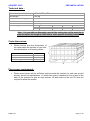
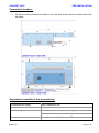
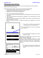
CONCEPT 305 PROCESSOR PRE-INSTALLATION INSTALLATION USER’S MANUAL CONCEPT 305 P TABLE OF CONTENTS MACHINE DESCRIPTION: Manufacturer’s address: ....................................................................................................... 3 Range of application:............................................................................................................ 3 Maximum capacity of the unit: .............................................................................................. 3 Principle description: ............................................................................................................ 3 Safety Warnings: .................................................................................................................. 4 PRE-INSTALLATION: Technical datas : .................................................................................................................. 5 Crate dimension: .................................................................................................................. 5 Floor space requirement: ..................................................................................................... 5 Connections location : .......................................................................................................... 6 Accessories needed for the connections: ............................................................................. 6 INSTALLATION: Unpacking: ........................................................................................................................... 7 Parts delivered with the machine :........................................................................................ 7 Connections: ........................................................................................................................ 8 USER'S MANUAL: Initial operation of the machine: ........................................................................................... 9 Machine configuration: ....................................................................................................... 10 Value modification: ............................................................................................................. 11 Plate data’s memorisation: ................................................................................................. 12 Start a Washout cycle : ...................................................................................................... 14 Remaining times for plates: ................................................................................................ 14 Process visualisation: ......................................................................................................... 14 Processing plate after plate: ............................................................................................... 15 Alarms: ............................................................................................................................... 16 To switch off the machine:.................................................................................................. 17 Edition AA, July 2010 This book has part No. 10068547 CONCEPT 305 P MACHINE DESCRIPTION Manufacturer’s address: DEGRAF S.p.A. "Il Girasole" - Palazzo Donatello 8/03b 20084 Lacchiarella (MI) Italy Range of application: This unit is part of a full range designed for treatment of flexographic printing plates. This range includes exposure, processor, dryer and light finisher. This unit is designed to wash out solvent washable printing plates. All other steps of the process are carried out on the other components of the range. Maximum capacity of the unit: Number of plates: 3 Minimum plate size: A4 Maximum plate size: 36 x 48 inches 900 x 1200 mm Warning: This unit is designed to work with solvent and has been tested with conventional product. Always ask your dealer before trying to change the type of solvent. This may result in major damages and safety issues. This machine has not been designed as an explosion proof unit. Principle description: • • • This unit is designed to wash and clean printing plates after the exposure process. The machine is divided in major sections: o Input table and control panel: Allow the operator to place the plate into the machine and select the correct parameters to process it. o Washout section: Designed to provide high quality and even washing out of the plates. o Cleaning section: Designed to ensure the cleaning and the wiping of the plate. o Exit section. The machine is operated via a specific control panel which ensures a very easy handling. Edition AA Page 3 / 18 CONCEPT 305 P MACHINE DESCRIPTION Safety Warnings: To use this unit safely, it is essential that operator and maintenance people follow the safety instructions and safety precautions and warnings specified in the manuals. The unit is equipped with emergency switches which allow the operator to stop the machine in case of an emergency. These emergency switches cut off the power supply of the entire machine. Make sure that the risk or the problem has been eliminated before restoring the power on the unit. To release the emergency switches, turn clockwise. The unit then has to be re-started following the “Initial operation”- procedure. Safety Interlocks For the safety of operators, interlocks exist for the following: • Opening the top covers during operation, • Overheating • Safety Level Switches Edition AA Page 4 / 18 CONCEPT 305 P PRE-INSTALLATION Technical data : Dimensions (w x l x h) : 1 680 x 3 350 x 970 mm Net Weight : 1 000 kg Compressed air supply: 6 bar minimum Exhaust: Noise Emission: Power supply : 600 m³/h minimum < 70 dB (A) 400 V 3Ph / N / PE 50/60 Hz 6,5 kW 10 A 230 V 50/60 Hz 6,5 kW 16 A 3Ph / PE Note : It is possible to dismantle a part of the exit section of the machine in order to reduce the length to 2050 mm to solve specific handling issues. Crate dimensions: • Please ensure that the dimensions of the crate match the facilities of your site: door dimensions, soil bearing values … W: L: H: Gross weight 1 920 mm 2 370 mm 1 760 mm 1 300 Kg Floor space requirement: • Please ensure there will be sufficient space around the machine for safe use as well as easy access for maintenance. 1.5 meter free space is needed in front of and on the back of the machine to give an easy access. On both sides of the unit 750 mm are required to allow the access. Edition AA Page 5 / 18 CONCEPT 305 P PRE-INSTALLATION Connection location: • All the connection points are located on the rear side of the machine underneath of the exit table. Accessories needed for the connections: Compressed air supply: Hose, diameter 6 mm Exhaust : Hose, diameter 140 mm Power supply : 5 x 6 mm² cable for the 400 V configuration 4 x 6 mm² cable for the 230 V configuration Solvent : Edition AA Hose, solvent resistant, diameter 20 mm Page 6 / 18 CONCEPT 305 P INSTALLATION Upon receipt of your machine please check with the carrier the status of the crate. Notify him of any damage you see on the crate. Before starting to unpack the unit, make sure you have all required tools ready to hand. Unpacking: Warning: For safety reasons, please wear appropriate protective clothing (gloves, glasses, and safety shoes) while unpacking. • • • • • • • • • • • • • Start by removing the top section of the crate. Remove the sides one by one. The machine is now resting on the base of the crate. Remove all blocking pieces of wood. Remove the exit section from the top of the processor. Use the appropriate forklift to lift the unit and get it to its installation location. Take care that the forks are long enough to lift the machine without causing damage. Put the exit section on the back of the processor. Put the transfer chains in place. Make the electrical connections in between the two sections. Ensure there is sufficient space around the machine (see Pre-installation section). Remove all protection from the unit (do not use sharp tools to prevent damages). No special anchorage is needed for this unit. The unit will rest only on its feet. Align the machine precisely by means of a water gauge. The alignment is made by using the adjustable feet. Parts supplied with the machine : Items : Pin bar Hose diameter 140 mm Locking collars (diameter 140 mm) Panel key High level used solvent sensor Plug and cable for used solvent sensor Low level fresh solvent sensor Plug and cable for fresh solvent sensor Used solvent barrel adapter Fresh solvent barrel adapter Solvent hoses (diameter 20 mm) with fittings Towel Fixation bar for towel Catch Tray Set of fuses Tube for compressed air Punch device Exit tray Qty : 2 3m 2 1 1 1 1 1 1 1 2x3m 1 1 1 1 3m 1 1 Verify, that all parts are with the machine. Edition AA Page 7 / 18 CONCEPT 305 P INSTALLATION Connections: All necessary connections have to be carried out in accordance with the rules and regulations of the installation country. Electrical connection : • Connections such as electrical power supply have to be carried out by certified personnel. • It is recommended to use a ground fault circuit breaker as well as a lockout type power switch for the electrical connection. • Before switching the machine on, measure the voltage on the main switch of the machine and make sure that it matches the value on the identification plate which is fixed on the back of the unit. Exhaust blower connection: • Connect all the exhaust hoses to the appropriate location (directly to the outside or to the building exhaust installation). Ensure the airflow is correct. Compressed air connection: • Connect the compressed air line to the unit. Solvent connection: • Connect the solvent lines to the correct points. • Connect the solvent level sensors (high level used solvent and low level fresh solvent) to the correct plugs. Filling the heater/cooler tank: • Remove the panel located on the left side of the unit. • Remove the cover of the heater/cooler tank. • Prepare 3 litres of a solution based on 70% of de-mineralized water (or distilled water), 30% of ethylene glycol and some drops of algaecide (anti-foam action). • Fill the tank to the maximum. • After operating the unit for a couple of minutes, it may be necessary to check the level of the heater/cooler tank again and to add solution to reach the correct level. Note: This operation has to be made with the machine switched OFF. WARNING: PRIOR TO USE THE MACHINE IT IS REQUIRED TO CHECK THE PRESSURE OF THE WASHOUT BRUSHES. PLEASE REFER TO THE RESPECTIVE SECTION IN THE TECHNICAL MANUAL FOR DETAILED PROCEDURE. WARNING: PRIOR TO USE THE MACHINE IT IS REQUIRED TO CONTROL THE DOCTOR BLADES ON THE WIPING BRUSH AND THE TOP AND BACK CLEANING BRUSH. IT SHOULD BE ADJUSTED TO BE ABOUT 3mm DEEP IN THE BRUSH. NOT DOING THIS MAY DAMAGE THE BRUSH Edition AA Page 8 / 18 CONCEPT 305 P USER’S MANUAL Initial operation of the machine: Before switching the machine on make sure that the working area around the machine is clean and free for easy movement. Check if there are any leaks of solvent as well as all the needed supplies: Electrical power supply: cable connected and not damaged. Compressed air: filter clean and pressure correct. Exhaust: hose connected and not damaged. • • You are now ready to switch the machine on. Turn the main switch of the machine which is located at the front of the machine (righthand side). • Verify, that all emergency stop buttons are released. If not, release them by turning them clockwise. • Switch the machine on by pressing the ON/OFF button which is located beneath the control panel of the machine. • When the machine is switched on different screens can be displayed on the touch screen: The machine is performing an automatic cleaning cycle when it is switched ON. This screen disappears as soon as the cleaning cycle is finished. The machine has been stopped with at least 1 plate in process. Keep pressing “RESET UNIT” for a few seconds to reset all the on going cycles. Keep pressing “RESTART UNIT” for a few seconds to restart the machine at exactly the same status of the power switch OFF. This allows to continue the process of a plate remaining inside the unit. The cleaning cycle has been cancelled and the display shows directly the process cycle screen. Edition AA Page 9 / 18 CONCEPT 305 P USER’S MANUAL Machine configuration: For access to the machine set-up, press the designated key. The machine configuration screen allows you to set the machine: Sets the display of the machine in “mm” or in “inches”. Simply press the corresponding key to switch the machine to the desired mode. Sets the display of the machine in “°C” or in “°F”. Simply press the key to switch from one mode to the other. Switches the display from the washout speed to the washout time. Press the key to switch from one mode to the other. The machine configuration screen allows you to modify: The solvent temperature (displayed in °C or °F). The maximum percentage of solids in the solvent (for the replenishment of the washout solvent). The time of the washout solvent circulation as well as the interval time between two circulations. The length of the fresh solvent pulses during the cleaning of the plate as well as the distance between these pulses. To modify the distance Password : used to access the restricted access screen (refer to “Technical manual”). Edition AA or . The between the pulses press distance is displayed in both “mm” and “inches”. Page 10 / 18 CONCEPT 305 P USER’S MANUAL Value modification: • To change a value (numeric or alpha numeric) directly press the desired value and the corresponding keypad will appear. Alpha numeric keypad: Numeric keypad: • Enter the new value and then confirm by pressing • • . To close the keypad, press If the entered value is out of range of the data it will return automatically to the minimum or maximum range limit. Note: these range limits are different for the same data depending on the setup of the machine. . The data are automatically stored in memory as soon as the key Edition AA is pressed. Page 11 / 18 CONCEPT 305 P USER’S MANUAL Plate data memorisation: 20 memory channels are available to store the plate data. or To switch from one channel to another simply press then displayed. . The memorised data are Parameters are different depending on the configuration of the solid content measuring device (refer to Technical manual: Solid content measuring device). Machine with solid content measurement activated: Press this zone to enter the plate type with the alpha numeric keypad. Press this zone to enter the washout speed with the numeric keypad. To recall an existing plate type simply press or . Note : Depending on the setup of the machine, the washout speed is displayed in mm/min., inches/min. or in time (min). Edition AA Page 12 / 18 CONCEPT 305 P USER’S MANUAL Machine with solid content measurement deactivated: Press this zone to enter the plate type with the alpha numeric keypad. Press this zone to enter the washout speed with the numeric keypad. Press this zone to enter the plate relief (in mm or inches depending on the machine configuration). Press this zone to enter the plate width (in mm or inches depending on the machine configuration). To recall an existing plate type simply press or . Note : Depending on the setup of the machine, the washout speed is displayed in mm/min., inches/min Edition AA Page 13 / 18 CONCEPT 305 P USER’S MANUAL Start a Washout cycle: WARNING: BEFORE STARTING THE FIRST WASHOUT CYCLE AFTER THE MACHINE INSTALLATION IT IS REQUIRED TO CHECK THE PRESSURE OF THE WASHOUT BRUSHES. PLEASE REFER TO THE RESPECTIVE SECTION IN THE TECHNICAL MANUAL FOR DETAILED PROCEDURE. • First select the required program by using the • keys or . Verify, that all parameters are correct. Open the entrance cover. Place the transport bar on the entrance table and ensure it is well engaged in the locking devices located on each side : must have the 2 “OK” signs on the screen. Fix the plate in the middle of the transport bar to allow the plate length sensor (located in the middle of the entrance section) to detect the plate properly. Close the entrance cover. • To start the cycle, press • • • • OK OK . Remaining process times for plates: • 3 bar graphs are available to indicate the remaining process time of each plate. Note : The calculation of the remaining time is based on the speed of the chain. Times can change quickly if the speed of the chain changes (for example if a second plate is put inside the machine or if the chain switches to high speed for transferring the plate at the end of the exit section after its cleaning). Process visualisation: • During the cycle a touch of the designated key switches the display to the dynamic synoptic screen of the machine. • All functions running are coloured in black. Edition AA Page 14 / 18 CONCEPT 305 P USER’S MANUAL Processing plate after plate: • It is possible to process several plates in the machine at the same time if the washout speed is the same. In this case, place the plate with the transport bar in the entrance and press program. • . The cycle will automatically start corresponding to the selected If the washout speed of the plate is different, place the plate with the transport bar in the entrance and press . The cycle will automatically start as soon as the previous plate has left the cleaning section. Note : The machine can process a maximum of 3 plates at the same time. Note : The sensor which measures the length of the plate is located in the middle of the unit. Take care to position the plate in front of this sensor. Edition AA Page 15 / 18 CONCEPT 305 P USER’S MANUAL Alarms: • • • If an alarm is detected an intermittent sound as well as a specific alarm sign are switched on. To see which alarm is on press the alarm sign to switch to the dynamic synoptic screen. A graphic alarm signal indicates the type of alarm (refer to following examples): o Level problem of the different solvent tanks. The warning signal is blinking near the corresponding level indication. o Excess temperature (of solvent or water). The warning signal is blinking near the solvent or water temperature indication. o Problem on a circuit breaker for the pumps and motors. The warning signal is blinking near the malfunctioning motor, pump or circuit breaker. Edition AA Page 16 / 18 CONCEPT 305 P USER’S MANUAL To switch the machine off: In order to allow the machine to perform the cleaning cycle when the machine is switched off, please use the “OFF” key which is located on the main screen. Keep this key pressed for a few seconds in order to start the cleaning cycle. At its end the machine will automatically switch off. The cleaning cycle performs the cleaning of all brushes using fresh solvent (refer to the “Technical Manual: Machine setup”). Edition AA Page 17 / 18 CONCEPT 305 P USER’S MANUAL Eng. Version AA: 07/2010 Eng. Version 1.0: 12/2007 Edition AA Page 18 / 18