1
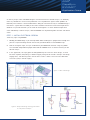
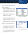
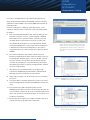
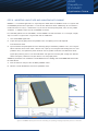
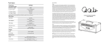
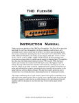
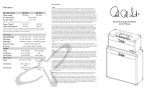
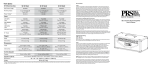
High-Power Amplifier
Design Example
featuring AWR Microwave Office™
and CapeSym SYMMIC software
AWR® Connected
for CapeSym
SYMMIC™
Application Note
Introduction
SYMMIC from CapeSym is a template-based thermal simulator that has been
optimized for monolithic microwave integrated circuit (MMIC) design. This
application note demonstrates the integration of Microwave Office and SYMMIC.
The integration is script-based and requires minimum manual intervention as
compared to non-integrated thermal solvers. The example used here is an
extension of the MMIC high power amplifier (HPA) example that is part of the
standard Microwave Office set of examples.
Background
SYMMIC’s template based approach allows the user to define the process
technology and thermal stackup separately from the circuit layout. These
templates can then be reused for different designs. Once a template is defined for
your GaAs MMIC, for example, it’s a simple matter to switch to an RF/microwave
design focus--simply updating the layout and DC power settings in SYMMIC--to
analyze the thermal performance of your designs. SYMMIC can be used beyond
the MMIC for modules and subsystems, as well as for transient and steady-state
analysis with flexible boundary conditions that includes radiative effects.
This application note will focus on a MMIC in steady-state to show the basic
operation and utility of the integration and the ease of use of SYMMIC with
Microwave Office.
It is assumed that SYMMIC has been installed on the same computer as
Microwave Office and that the Microwave Office script provided by SYMMIC has
been installed properly within the AWR Design Environment™.
What Makes symmic different?
Most thermal analysis tools are optimized and designed for general problems in
thermal simulation This generalitzation makes them difficult to learn and use.
SYMMIC takes a totally different approach to significantly reduce complexities
and barriers for a MMIC designer. The template-based notion of thermal design
relieves the electrical engineer from nearly all the burden of creating robust
thermal simulations. To be sure, issues like thermal boundary conditions and
material properties still need to be understood, but the particulars involved can be
investigated as part of the design process and not a precursor to it. SYMMIC is the
first tool that brings thermal analysis to the realm of MMIC design.
What’s more SYMMIC is fast. If you have a desktop workstation that uses a
multi-processor, 64-bit AXIEM®, SYMMIC can take full advantage of this same
hardware configuration. The simulations in this application note were run on
an 8-core 16GB Windows PC running 64-bit XP. This is highly conducive to an
iterated design flow where FET bias points can be chosen with regard to thermal
conditions as well as electromagnetic. It is entirely possible to now design
concurrently for reliability and electrical performance.
SYMMIC Thermal
Simulation from
Microwave Office
Projects
AWR®
CapeSym
SYMMIC™
Application Note
As with any analysis tool—and MMIC designers are well aware of this with EM analysis—an absolutely
necessary condition for successful and productive use is to profile them against known problems or
laboratory measurements. One of the difficulties in doing this with thermal analysis and MMIC design is
that there is a great deal of variability in the various methods used to measure channel temperatures1.
While this may create controversy in the minds of some engineers as to the absolute temperature
values indicated by a thermal analysis, tools like SYMMIC are still powerful guides to trends and relative
values.
step 1 - initial electrical design
Three easy steps using SYMMIC:
1. Develop your MMIC design as you normally would. When the design has progressed far enough that
you have a layout containing thermal sources then you will be able to run the SYMMIC script.
2. Prior to running the script, set up an annotation on your MMIC-level schematic using TOT_PWRA.
This annotation will provide the proper information for SYMMIC to use as the heat source(s) for the
thermal analysis.
3. In this application, we simply open the HPA_MMIC.emp file. From this basic design, an initial
low noise amplifier (LNA) design is added simply by taking two of the FETs already in the design,
copying them, and rebiasing them so their drain current is about 10% of that for field effect
transistors (FET) in the PA stage(s).
Figure 1. H
PA + LNA design.
Figure 2. S
imple LNA design starting point added
for early thermal analysis.
AWR
CapeSym
SYMMIC
Application Note
step 2 - Prepare and run Microwave Office
symmic script
In this section, the SYMMIC data is created in Microwave Office and
prepared for exporting to SYMMIC.
1. First, run the script from the Script pull-down menu. Depending
on how the script was installed in the AWR Design Environment,
this script will appear in different places: global scripts or project
scripts. (See the AWR Design Environment User Manual if you
cannot find the script or the proper procedure for its installation.)
The script begins by prompting you for the layout that will be used
for the physical data and the schematic that will be used for the
electrical information (figure 3).
2. The schematic containing the entire MMIC layout should be
selected from the first column (here, HPA_MMIC). The schematic
containing the placed MMIC which has the TOT_PWRA annotation
should be selected from the second column
(here, -NL_WholeAmp).
3. Click Begin Layout. Two windows open. SYMMIClayout is a datafile
Figure 3. S
YMMIC thermal analysis script - dialog 1:
Selection of MMIC layout and MMIC electrical
information.
window, which will be populated xml information describing the
FETs and their location. SYMMICPwr is a table-formatted graph
which will display the annotated power information from the
TOT_PWRA annotations for the devices you select. Note: If you
do not select the Create Power Table From checkbox in the dialog
(figure 3), then the graph will not be created. The graph does not
need to be created as the information can be read directly from
the related schematic and entered manually in SYMMIC.
In the next few steps, the layout hierarchy is traversed to find the devices
which will be used as sources and analysis points within the thermal
simulation.
4. Click the Browse button and select a template to use for the chosen
devices. The templates are *.xml files exported from SYMMIC and
are technology-based. Since the HPA_MMIC has been previously
analyzed by SYMMIC, templates are already available for the FETs.
These device templates contain all of the material and layout
information regarding the device. The electrical information is stored
separately. This allows for fast transfer of data from Microwave
Office to SYMMIC as it reduces the datafile size where FETs of
common size are re-used in the design. This also allows SYMMIC
to separate material and layout information from electrical power
dissipation information which speeds up iteration time as bias
schemes vs. temperature are explored.
Figure 4. S
YMMIC thermal analysis script - dialog 2:
From the top-level hierarchy the layout is
traversed to find the source/analysis devices.
AWR
CapeSym
SYMMIC
Application Note
If this were a new MMIC design using a different FET periphery, the
design would need to be imported into SYMMIC and the xml template
updated from within SYMMIC. Consult the SYMMIC documentation for
more information.
Once the xml template is available for a given device layout, it is reuseable for all devices with that layout even if they have different power
dissipations.
5. From the Analyze Selected Devices box, select the device you wish
to include in the thermal analysis. A device template in SYMMIC
often models half of a symmetrical device. If you wish to analyze
the entire device in the simulation using mirror symmetry, click
the checkbox Mirror Template in X. The Angle Of Device Relative
To Template dropdown item can be used to indicate the difference
in orientation of the device in the MWO library in your layout as
compared to how it was stored in relative to that of the template in
SYMMIC.
Figure 5. SYMMIC thermal analysis script - dialog 3:
Select devices corresponding to layout cells
which are to be analyzed using the template
outputFET.xml. Clicking “Add to Layout” will
force these to appear in the SYMMIClayout
data file.
6. For the device selected in step 5 above, find the hierarchical
element corresponding to the layout cell for that device. In the case
of the OutputFET selected in figure 4, we must go down 1 level of
hierarchy. To do this, click the Enter Hierarchy Subcircuit button
and select all of the elements associated comprising the artwork
described by the template. In figure 5, the eight elements selected
all use this single template.
7. Click Add To Layout to add these devices to the layout to be
analyzed. The SYMMIClayout datafile window is updated with the
identifying information and locations for these devices.
8. Repeat steps 5 through 7 for all the devices you wish to include in
the analysis.
9. Once all the devices have been selected for inclusion in the analysis,
Figure 6. SYMMIClayout data file created by the
SYMMIC script in Microwave Office.
click the Complete button to finalize the SYMMIClayout and exit the
script.
10. From the Data Files node of the project palette, find the
SYMMIClayout file, right mouse-click and select Export Data File. You
must include the .xml extension to the file name before exporting the
design. You are free to name the file whatever you want, but it must
include the .xml extension.
11. Simulate your circuit to get the TOT_PWRA annotation values or to
calculate the values in the power table, if generated.
Figure 7. Exporting the xml file from the Data Files
node of the Project palette.
AWR
CapeSym
SYMMIC
Application Note
step 3 - importing layout into and analyzing with symmic
SYMMIC is a stand-alone application run separately from AWR software. SYMMIC can be run anytime after
the SYMMIClayout datafile is exported as an xml file from Microwave Office. Additionally, for each device in
the desired thermal analysis, it will be necessary to have the total dissipated power, from the TOT_PWRA
annotation, as additional input data for the SYMMIC simulation.
For a detailed guide to the use of SYMMIC, see the SYMMIC user documentation. As an example, step-bystep instructions are given here using the HPA with the added LNA.
1. Start the SYMMIC application.
2. Import the layout by going to the File pull-down menu and opening the xml file exported
from Microwave Office.
3. Input the device dissipated power for each device by going to the Device pull-down menu, and using the
Device selection command to select a device. Then, open up the heat generation dialog (from the same
pull-down menu), and update the power based on the TOT_PWRA annotation from Microwave Office
(figure 8) by selecting the first row Total ON Power and right-mouse clicking Edit. Change the selected
device and repeat/validate that all your devices have the proper power.
Additional parameters for the device can be edited from this dialog. See the SYMMIC documentation
for more details.
4. Run the thermal analysis from the Solve pull-down menu.
5. Results can be viewed from the results pull-down menu.
Figure 8. S
YMMIC with imported xml file and dialog for updating/verifying dissipated power for each FET.
AWR
CapeSym
SYMMIC
Application Note
Results for hpa+lna
Two different simulations were run with HPA+LNA MMIC. In the first
simulation (figure 9), the HPA is off and the LNA is running at its
nominal value of 50 mW. The channel temperature for the LNA FETs
is approximately 8 deg above baseplate.
In the second simulation, the HPA and the LNA are both operational.
The HPA is running at approximately 450 mW dissipated power per
FET in the output stage and in the driver stage—clearly this is an
exceptionally “hot” test condition. In this configuration (figure 10), the
output stage FETs vary over about 20 deg C, with the hottest FET
running almost 90 deg C above baseplate. The LNA FETs though are
now about 13 deg C above the baseplate—perhaps a bit warmer than
when they are the only thermal source, but not as hot as one would
expect with the HPA in an extreme condition.
Figure 9. S
YMMIC simulation for HPA + LNA MMIC with
HPA off and LNA at nominal.
conclusion
Thermal simulation is now a reality for the MMIC designer not as an
esoteric piece of mechanical engineering software, but as an integrated
part of an RF/microwave design flow. SYMMIC’s template-based approach
and sheer simulation speed combined with its scripted integration to
Microwave Office means that more accurate device simulation is possible
for electrical circuit design. Reliability can be concurrently considered with
electrical performance in simulations that take no longer than a detailed,
3D planar EM simulation.
Figure 10. H
PA and LNA running simultaneously.
AWR, 1960 East Grand Avenue, Suite 430, El Segundo, CA 90245, USA
Tel: +1 (310) 726-3000 Fax: +1 (310) 726-3005
www.awrcorp.com
Copyright © 2011 AWR Corporation. All rights reserved. AWR and the AWR logo, and AXIEM are registered
trademarks and AWR Design Environment and Microwave Office are trademarks of AWR Corporation.
All other trademarks are trademarks of their respective owners.