1
600-uC-FS-002.book Page 1 Wednesday, July 3, 2013 1:26 PM
μC/ FS
TM
The Embedded File System
User’s Manual
600-uC-FS-002.book Page 2 Wednesday, July 3, 2013 1:26 PM
Micriμm
1290 Weston Road, Suite 306
Weston, FL 33326
USA
www.micrium.com
Designations used by companies to distinguish their products are often claimed as
trademarks. In all instances where Micriμm Press is aware of a trademark claim, the product
name appears in initial capital letters, in all capital letters, or in accordance with the
vendor’s capitalization preference. Readers should contact the appropriate companies for
more complete information on trademarks and trademark registrations. All trademarks and
registered trademarks in this book are the property of their respective holders.
Copyright © 2013 by Micriμm except where noted otherwise. All rights reserved. Printed in
the United States of America. No part of this publication may be reproduced or distributed
in any form or by any means, or stored in a database or retrieval system, without the prior
written permission of the publisher; with the exception that the program listings may be
entered, stored, and executed in a computer system, but they may not be reproduced for
publication.
The programs and code examples in this book are presented for instructional value. The
programs and examples have been carefully tested, but are not guaranteed to any particular
purpose. The publisher does not offer any warranties and does not guarantee the accuracy,
adequacy, or completeness of any information herein and is not responsible for any errors
or omissions. The publisher assumes no liability for damages resulting from the use of the
information in this book or for any infringement of the intellectual property rights of third
parties that would result from the use of this information.
600-uC-FS-002
600-uC-FS-002.book Page 3 Wednesday, July 3, 2013 1:26 PM
Table of Contents
Chapter 1
1-1
1-2
1-3
1-4
Introduction .......................................................................................... 15
μC/FS .................................................................................................... 15
Typical Usages ..................................................................................... 17
Why FAT? ............................................................................................. 17
Chapter Contents ................................................................................. 18
Chapter 2
2-1
2-1-1
2-1-2
2-1-3
2-1-4
2-1-5
2-1-6
2-1-7
2-1-8
μC/FS Architecture .............................................................................. 23
Architecture Components ................................................................... 25
Your Application ................................................................................... 25
μC-LIB (Libraries) ................................................................................. 25
POSIX API Layer .................................................................................. 25
FS Layer ............................................................................................... 26
File System Driver Layer ...................................................................... 27
Device Driver Layer .............................................................................. 27
μC-CPU ................................................................................................ 28
RTOS Layer .......................................................................................... 28
Chapter 3
3-1
3-2
3-3
3-4
3-5
3-6
3-7
3-8
3-9
3-10
3-11
μC/FS Directories and Files ................................................................. 29
Application Code ................................................................................. 32
CPU ....................................................................................................... 34
Board Support Package (BSP) ............................................................ 35
μC/CPU, CPU Specific Source Code .................................................. 36
μC/LIB, Portable Library Functions ..................................................... 38
μC/Clk, Time/Calendar Management .................................................. 39
μC/CRC, Checksums and Error Correction Codes ............................ 41
μC/FS Platform-Independent Source Code ........................................ 42
μC/FS FAT Filesystem Source Code ................................................... 45
μC/FS Memory Device Drivers ............................................................ 46
μC/FS Platform-Specific Source Code ............................................... 50
3
600-uC-FS-002.book Page 4 Wednesday, July 3, 2013 1:26 PM
Table of Contents
3-12
3-13
μC/FS OS Abstraction Layer ............................................................... 51
Summary .............................................................................................. 52
Chapter 4
4-1
4-2
4-3
4-4
4-5
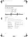
Useful Information ................................................................................ 59
Nomenclature ....................................................................................... 59
μC/FS Device and Volume Names ...................................................... 61
μC/FS File and Directory Names and Paths ....................................... 62
μC/FS Name Lengths ........................................................................... 64
Resource Usage ................................................................................... 65
Chapter 5
5-1
5-2
5-3
5-4
5-5
5-6
5-7
5-8
5-8-1
5-8-2
Devices and Volumes .......................................................................... 67
Device Operations ............................................................................... 68
Using Devices ...................................................................................... 69
Using Removable Devices ................................................................... 71
Raw Device IO ...................................................................................... 72
Partitions .............................................................................................. 73
Volume Operations .............................................................................. 76
Using Volumes ..................................................................................... 77
Using Volume Cache ............................................................................ 79
Choosing Cache Parameters ............................................................... 81
Other Caching and Buffering Mechanisms ......................................... 82
Chapter 6
6-1
6-1-1
6-1-2
6-1-3
6-1-4
6-1-5
6-2
6-2-1
6-2-2
6-2-3
Files ...................................................................................................... 83
File Access Functions .......................................................................... 84
Opening Files ....................................................................................... 85
Getting Information About a File ......................................................... 86
Configuring a File Buffer ...................................................................... 87
File Error Functions .............................................................................. 88
Atomic File Operations Using File Lock .............................................. 88
Entry Access Functions ....................................................................... 89
File and Directory Attributes ................................................................ 90
Creating New Files and Directories ..................................................... 91
Deleting Files and Directories ............................................................. 92
Chapter 7
7-1
Directories ............................................................................................ 93
Directory Access Functions ................................................................ 94
4
600-uC-FS-002.book Page 5 Wednesday, July 3, 2013 1:26 PM
Chapter 8
8-1
8-2
8-3
8-3-1
8-3-2
8-3-3
8-3-4
8-3-5
8-4
8-5
POSIX API ............................................................................................. 95
Supported Functions ........................................................................... 96
Working Directory Functions ............................................................... 97
File Access Functions .......................................................................... 98
Opening, Reading and Writing Files .................................................. 100
Getting or Setting the File Position ................................................... 103
Configuring a File Buffer .................................................................... 104
Diagnosing a File Error ...................................................................... 106
Atomic File Operations Using File Lock ............................................ 106
Directory Access Functions .............................................................. 107
Entry Access Functions ..................................................................... 109
Chapter 9
9-1
9-1-1
9-2
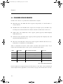
Device Drivers .................................................................................... 111
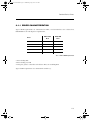
Provided Device Drivers .................................................................... 112
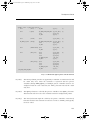
Driver Characterization ...................................................................... 113
Drivers Comparison ........................................................................... 115
Chapter 10
10-1
10-2
10-2-1
10-3
10-3-1
10-3-2
10-4
10-5
10-6
10-6-1
10-6-2
10-6-3
10-6-4
10-7
10-7-1
10-7-2
FAT File System ................................................................................. 117
Why Embedded Systems Use FAT ................................................... 117
Organization of a FAT Volume ........................................................... 118
Organization of Directories and Directory Entries ............................ 119
Organization of the File Allocation Table .......................................... 120
FAT12 / FAT16 / FAT32 ...................................................................... 122
Short and Long File Names ............................................................... 123
Formatting .......................................................................................... 126
Types of Corruption in FAT Volumes ................................................ 127
Optional Journaling System .............................................................. 127
What Journaling Guarantees ............................................................. 128
How Journaling Works ....................................................................... 128
How To Use Journaling ...................................................................... 129
Limitations Of Journaling ................................................................... 130
Licensing Issues ................................................................................. 132
Licenses for Long File Names (LFNs) ............................................... 132
Extended File Allocation Table (exFAT) ............................................ 132
5
600-uC-FS-002.book Page 6 Wednesday, July 3, 2013 1:26 PM
Table of Contents
Chapter 11
11-1
11-2
RAM Disk Driver ................................................................................. 133
Files and Directories .......................................................................... 133
Using the RAM Disk Driver ................................................................ 134
Chapter 12
12-1
12-2
12-2-1
12-2-2
12-2-3
12-3
12-3-1
12-3-2
12-3-3
SD/MMC Drivers ................................................................................ 137
Files and Directories .......................................................................... 139
Using the SD/MMC CardMode Driver ............................................... 140
SD/MMC CardMode Communication ............................................... 143
SD/MMC CardMode Communication Debugging ............................ 146
SD/MMC CardMode BSP Overview .................................................. 150
Using the SD/MMC SPI Driver ........................................................... 152
SD/MMC SPI Communication ........................................................... 155
SD/MMC SPI Communication Debugging ........................................ 156
SD/MMC SPI BSP Overview .............................................................. 159
Chapter 13
13-1
13-2
13-3
13-3-1
13-3-2
13-4
13-4-1
13-4-2
13-5
13-6
13-7
13-8
13-8-1
13-8-2
13-8-3
13-8-4
NAND Flash Driver ............................................................................. 161
Getting Started ................................................................................... 162
Architecture Overview ....................................................................... 169
NAND Translation Layer .................................................................... 170
Translation Layer Configuration ........................................................ 173
Translation Layer Source Files .......................................................... 180
Controller Layer .................................................................................. 180
Generic Controller Layer Implementation ......................................... 181
Part Layer ........................................................................................... 183
Board Support Package - Generic Controller .................................. 187
Board Support Package - Other Controllers .................................... 188
Performance Considerations ............................................................. 188
Development Guide ........................................................................... 190
BSP Development Guide - Generic Controller ................................. 190
Generic Controller Extension Development Guide ........................... 192
ECC Module Development Guide ..................................................... 194
Controller Layer Development Guide ................................................ 195
Chapter 14
14-1
14-2
14-3
NOR Flash Driver ............................................................................... 199
Files and Directories .......................................................................... 200
Driver and Device Characteristics ..................................................... 202
Using a Parallel NOR Device ............................................................. 204
6
600-uC-FS-002.book Page 7 Wednesday, July 3, 2013 1:26 PM
14-3-1
14-3-2
14-3-3
14-4
14-4-1
14-4-2
14-5
14-5-1
14-5-2
14-5-3
14-5-4
14-5-5
Driver Architecture ............................................................................. 208
Hardware ............................................................................................ 208
NOR BSP Overview ............................................................................ 210
Using a Serial NOR Device ................................................................ 211
Hardware ............................................................................................ 212
NOR SPI BSP Overview ..................................................................... 213
Physical-Layer Drivers ....................................................................... 214
FSDev_NOR_AMD_1x08, FSDev_NOR_AMD_1x16 .......................... 215
FSDev_NOR_Intel_1x16 ..................................................................... 215
FSDev_NOR_SST39 ........................................................................... 216
FSDev_NOR_STM25 .......................................................................... 216
FSDev_NOR_SST25 ........................................................................... 217
Chapter 15
15-1
15-2
MSC Driver ......................................................................................... 219
Files and Directories .......................................................................... 219
Using the MSC Driver ........................................................................ 220
Appendix A
A-1
A-1-1
A-1-2
A-1-3
A-1-4
A-1-5
A-2
A-2-1
A-2-2
A-2-3
A-2-4
A-2-5
A-2-6
A-2-7
A-2-8
A-2-9
A-2-10
A-2-11
A-2-12
A-2-13
μC/FS API Reference ......................................................................... 223
General File System Functions .......................................................... 225
FS_DevDrvAdd() ................................................................................. 226
FS_Init() ............................................................................................... 227
FS_VersionGet() .................................................................................. 228
FS_WorkingDirGet() ........................................................................... 229
FS_WorkingDirSet() ............................................................................ 230
Posix API Functions ........................................................................... 231
fs_asctime_r() ..................................................................................... 234
fs_chdir() ............................................................................................. 235
fs_clearerr() ......................................................................................... 236
fs_closedir() ........................................................................................ 237
fs_ctime_r() ......................................................................................... 238
fs_fclose() ........................................................................................... 239
fs_feof() ............................................................................................... 240
fs_ferror() ............................................................................................ 241
fs_fflush() ............................................................................................ 242
fs_fgetpos() ......................................................................................... 243
fs_flockfile() ........................................................................................ 244
fs_fopen() ............................................................................................ 245
fs_fread() ............................................................................................. 246
7
600-uC-FS-002.book Page 8 Wednesday, July 3, 2013 1:26 PM
Table of Contents
A-2-14
A-2-15
A-2-16
A-2-17
A-2-18
A-2-19
A-2-20
A-2-21
A-2-22
A-2-23
A-2-24
A-2-25
A-2-26
A-2-27
A-2-28
A-2-29
A-2-30
A-2-31
A-2-32
A-3
A-3-1
A-3-2
A-3-3
A-3-4
A-3-5
A-3-6
A-3-7
A-3-8
A-3-9
A-3-10
A-3-11
A-3-12
A-3-13
A-3-14
A-3-15
A-3-16
A-4
A-4-1
8
fs_fseek() ............................................................................................ 247
fs_fsetpos() ......................................................................................... 249
fs_ftell() ............................................................................................... 250
fs_ftruncate() ...................................................................................... 251
fs_ftrylockfile() .................................................................................... 252
fs_funlockfile() .................................................................................... 253
fs_fwrite() ............................................................................................ 254
fs_getcwd() ......................................................................................... 255
fs_localtime_r() ................................................................................... 256
fs_mkdir() ............................................................................................ 257
fs_mktime() ......................................................................................... 258
fs_opendir() ......................................................................................... 259
fs_readdir_r() ...................................................................................... 260
fs_remove() ......................................................................................... 261
fs_rename() ......................................................................................... 263
fs_rewind() .......................................................................................... 265
fs_rmdir() ............................................................................................. 266
fs_setbuf() ........................................................................................... 267
fs_setvbuf() ......................................................................................... 268
Device Functions ............................................................................... 270
FSDev_AccessLock() ......................................................................... 273
FSDev_AccessUnlock() ...................................................................... 274
FSDev_Close() .................................................................................... 275
FSDev_GetDevName() ....................................................................... 276
FSDev_GetDevCnt() ........................................................................... 277
FSDev_GetDevCntMax() .................................................................... 278
FSDev_GetNbrPartitions() .................................................................. 279
FSDev_Invalidate() ............................................................................. 280
FSDev_Open() .................................................................................... 281
FSDev_PartitionAdd() ......................................................................... 283
FSDev_PartitionFind() ........................................................................ 284
FSDev_PartitionInit() .......................................................................... 286
FSDev_Query() ................................................................................... 287
FSDev_Rd() ......................................................................................... 288
FSDev_Refresh() ................................................................................. 289
FSDev_Wr() ......................................................................................... 291
Directory Access Functions .............................................................. 292
FSDir_Close() ...................................................................................... 293
600-uC-FS-002.book Page 9 Wednesday, July 3, 2013 1:26 PM
A-4-2
A-4-3
A-4-4
A-5
A-5-1
A-5-2
A-5-3
A-5-4
A-5-5
A-5-6
A-5-7
A-6
A-6-1
A-6-2
A-6-3
A-6-4
A-6-5
A-6-6
A-6-7
A-6-8
A-6-9
A-6-10
A-6-11
A-6-12
A-6-13
A-6-14
A-6-15
A-6-16
A-6-17
A-7
A-7-1
A-7-2
A-7-3
A-7-4
A-7-5
A-7-6
A-7-7
A-7-8
FSDir_IsOpen() ................................................................................... 294
FSDir_Open() ...................................................................................... 295
FSDir_Rd() .......................................................................................... 296
Entry Access Functions ..................................................................... 297
FSEntry_AttribSet() ............................................................................. 298
FSEntry_Copy() .................................................................................. 300
FSEntry_Create() ................................................................................ 302
FSEntry_Del() ...................................................................................... 304
FSEntry_Query() ................................................................................. 306
FSEntry_Rename() .............................................................................. 307
FSEntry_TimeSet() .............................................................................. 309
File Functions ..................................................................................... 311
FSFile_BufAssign() ............................................................................. 313
FSFile_BufFlush() ............................................................................... 315
FSFile_Close() ..................................................................................... 316
FSFile_ClrErr() .................................................................................... 317
FSFile_IsEOF() .................................................................................... 318
FSFile_IsErr() ...................................................................................... 319
FSFile_IsOpen() .................................................................................. 320
FSFile_LockAccept() .......................................................................... 321
FSFile_LockGet() ................................................................................ 322
FSFile_LockSet() ................................................................................ 323
FSFile_Open() ..................................................................................... 324
FSFile_PosGet() .................................................................................. 326
FSFile_PosSet() .................................................................................. 327
FSFile_Query() .................................................................................... 329
FSFile_Rd() ......................................................................................... 330
FSFile_Truncate() ............................................................................... 332
FSFile_Wr() ......................................................................................... 333
Volume Functions .............................................................................. 335
FSVol_Close() ..................................................................................... 337
FSVol_Fmt() ........................................................................................ 338
FSVol_GetDfltVolName() .................................................................... 340
FSVol_GetVolCnt() .............................................................................. 341
FSVol_GetVolCntMax() ....................................................................... 342
FSVol_GetVolName() .......................................................................... 343
FSVol_IsDflt() ...................................................................................... 344
FSVol_IsMounted() ............................................................................. 345
9
600-uC-FS-002.book Page 10 Wednesday, July 3, 2013 1:26 PM
Table of Contents
A-7-9
A-7-10
A-7-11
A-7-12
A-7-13
A-7-14
A-8
A-8-1
A-8-2
A-8-3
A-9
A-9-1
A-9-2
A-9-3
A-10
A-10-1
A-10-2
A-10-3
A-11
A-11-1
A-11-2
A-11-3
A-11-4
A-11-5
A-11-6
A-11-7
A-11-8
A-11-9
A-12
A-12-1
A-12-2
A-12-3
A-12-4
A-12-5
FSVol_LabelGet() ................................................................................ 346
FSVol_LabelSet() ................................................................................ 348
FSVol_Open() ...................................................................................... 350
FSVol_Query() ..................................................................................... 352
FSVol_Rd() .......................................................................................... 353
FSVol_Wr() .......................................................................................... 355
Volume Cache Functions ................................................................... 356
FSVol_CacheAssign() ......................................................................... 357
FSVol_CacheInvalidate () ................................................................... 359
FSVol_CacheFlush () .......................................................................... 360
SD/MMC Driver Functions ................................................................. 361
FSDev_SD_xxx_QuerySD() ................................................................ 362
FSDev_SD_xxx_RdCID() .................................................................... 364
FSDev_SD_xxx_RdCSD() ................................................................... 366
NAND Driver Functions ...................................................................... 368
FSDev_NAND_LowFmt() .................................................................... 369
FSDev_NAND_LowMount() ................................................................ 370
FSDev_NAND_LowUnmount() ........................................................... 372
NOR Driver Functions ........................................................................ 373
FSDev_NOR_LowFmt() ...................................................................... 374
FSDev_NOR_LowMount() .................................................................. 375
FSDev_NOR_LowUnmount() .............................................................. 376
FSDev_NOR_LowCompact() .............................................................. 377
FSDev_NOR_LowDefrag() .................................................................. 378
FSDev_NOR_PhyRd() ......................................................................... 379
FSDev_NOR_PhyWr() ......................................................................... 381
FSDev_NOR_PhyEraseBlk() ............................................................... 383
FSDev_NOR_PhyEraseChip() ............................................................ 385
FAT System Driver Functions ............................................................ 386
FS_FAT_JournalOpen() ...................................................................... 387
FS_FAT_JournalClose() ...................................................................... 388
FS_FAT_JournalStart() ....................................................................... 389
FS_FAT_JournalStop() ....................................................................... 390
FS_FAT_VolChk() ................................................................................ 391
Appendix B
B-1
B-2
μC/FS Error Codes ............................................................................. 393
System Error Codes ........................................................................... 393
Buffer Error Codes ............................................................................. 393
10
600-uC-FS-002.book Page 11 Wednesday, July 3, 2013 1:26 PM
B-3
B-4
B-5
B-6
B-7
B-8
B-9
B-10
B-11
B-12
B-13
B-14
B-15
Cache Error Codes ............................................................................ 394
Device Error Codes ............................................................................ 394
Device Driver Error Codes ................................................................. 395
Directory Error Codes ........................................................................ 395
ECC Error Codes ................................................................................ 395
Entry Error Codes .............................................................................. 395
File Error Codes ................................................................................. 396
Name Error Codes ............................................................................. 397
Partition Error Codes ......................................................................... 397
Pools Error Codes .............................................................................. 397
File System Error Codes .................................................................... 398
Volume Error Codes ........................................................................... 398
OS Layer Error Codes ........................................................................ 399
Appendix C
C-1
C-2
C-3
C-4
C-4-1
C-4-2
C-4-3
C-4-4
C-4-5
C-4-6
C-4-7
C-4-8
C-5
C-5-1
C-5-2
C-5-3
C-5-4
C-5-5
C-5-6
C-5-7
C-5-8
C-5-9
C-5-10
μC/FS Porting Manual ........................................................................ 401
Date/Time Management .................................................................... 403
CPU Port ............................................................................................. 403
OS Kernel ........................................................................................... 404
Device Driver ...................................................................................... 412
NameGet() .......................................................................................... 414
Init() ..................................................................................................... 415
Open() ................................................................................................. 416
Close() ................................................................................................. 418
Rd() ..................................................................................................... 419
Wr() ..................................................................................................... 421
Query() ................................................................................................ 423
IO_Ctrl() ............................................................................................... 424
SD/MMC Cardmode BSP .................................................................. 425
FSDev_SD_Card_BSP_Open() ........................................................... 429
FSDev_SD_Card_BSP_Lock/Unlock() ............................................... 430
FSDev_SD_Card_BSP_CmdStart() .................................................... 431
FSDev_SD_Card_BSP_CmdWaitEnd() .............................................. 436
FSDev_SD_Card_BSP_CmdDataRd() ............................................... 440
FSDev_SD_Card_BSP_CmdDataWr() ............................................... 443
FSDev_SD_Card_BSP_GetBlkCntMax() ............................................ 446
FSDev_SD_Card_BSP_GetBusWidthMax() ....................................... 447
FSDev_SD_Card_BSP_SetBusWidth() .............................................. 448
FSDev_SD_Card_BSP_SetClkFreq() ................................................. 450
11
600-uC-FS-002.book Page 12 Wednesday, July 3, 2013 1:26 PM
Table of Contents
C-5-11
C-5-12
C-6
C-7
C-7-1
C-7-2
C-7-3
C-7-4
C-7-5
C-7-6
C-7-7
C-8
C-9
C-9-1
C-9-2
C-9-3
C-9-4
C-9-5
C-9-6
C-10
C-10-1
C-10-2
C-10-3
C-10-4
C-10-5
C-10-6
C-11
FSDev_SD_Card_BSP_SetTimeoutData() ......................................... 451
FSDev_SD_Card_BSP_SetTimeoutResp() ........................................ 452
SD/MMC SPI mode BSP .................................................................... 452
SPI BSP .............................................................................................. 453
Open() ................................................................................................. 457
Close() ................................................................................................. 459
Lock() / Unlock() ................................................................................. 460
Rd() ..................................................................................................... 461
Wr() ..................................................................................................... 462
ChipSelEn() /ChipSelDis() .................................................................. 463
SetClkFreq() ........................................................................................ 464
NAND Flash Physical-Layer Driver .................................................... 464
NOR Flash Physical-Layer Driver ...................................................... 465
Open() ................................................................................................. 467
Close() ................................................................................................. 468
Rd() ..................................................................................................... 469
Wr() ..................................................................................................... 470
EraseBlk() ........................................................................................... 471
IO_Ctrl() ............................................................................................... 472
NOR Flash BSP .................................................................................. 473
FSDev_NOR_BSP_Open() .................................................................. 474
FSDev_NOR_BSP_Close() ................................................................. 475
FSDev_NOR_BSP_Rd_XX() ................................................................ 476
FSDev_NOR_BSP_RdWord_XX() ....................................................... 477
FSDev_NOR_BSP_WrWord_XX() ....................................................... 478
FSDev_NOR_BSP_WaitWhileBusy() .................................................. 479
NOR Flash SPI BSP ........................................................................... 480
Appendix D
D-1
D-2
D-3
D-4
D-5
D-6
D-7
D-8
D-9
μC/FS Types and Structures ............................................................. 481
FS_CFG .............................................................................................. 482
FS_DEV_INFO ..................................................................................... 484
FS_DEV_NOR_CFG ............................................................................ 485
FS_DEV_RAM_CFG ............................................................................ 488
FS_DIR_ENTRY (struct fs_dirent) ...................................................... 489
FS_ENTRY_INFO ................................................................................ 490
FS_FAT_SYS_CFG ............................................................................. 492
FS_PARTITION_ENTRY ..................................................................... 494
FS_VOL_INFO ..................................................................................... 495
12
600-uC-FS-002.book Page 13 Wednesday, July 3, 2013 1:26 PM
Appendix E
E-1
E-2
E-3
E-4
E-5
E-6
E-7
E-8
E-9
μC/FS Configuration .......................................................................... 497
File System Configuration ................................................................. 498
Feature Inclusion Configuration ........................................................ 500
Name Restriction Configuration ........................................................ 503
Debug Configuration .......................................................................... 504
Argument Checking Configuration .................................................... 504
File System Counter Configuration ................................................... 505
FAT Configuration .............................................................................. 505
SD/MMC SPI Configuration ............................................................... 506
Trace Configuration ........................................................................... 507
Appendix F
F-1
F-2
F-3
F-3-1
F-3-2
F-3-3
F-3-4
F-3-5
F-3-6
F-3-7
F-3-8
F-3-9
F-3-10
F-3-11
F-3-12
F-3-13
F-3-14
F-3-15
F-3-16
F-3-17
F-4
Shell Commands ................................................................................ 509
Files and Directories .......................................................................... 510
Using the Shell Commands ............................................................... 511
Commands ......................................................................................... 514
fs_cat .................................................................................................. 515
fs_cd ................................................................................................... 516
fs_cp ................................................................................................... 518
fs_date ................................................................................................ 519
fs_df .................................................................................................... 520
fs_ls ..................................................................................................... 521
fs_mkdir .............................................................................................. 522
fs_mkfs ............................................................................................... 523
fs_mount ............................................................................................. 524
fs_mv .................................................................................................. 525
fs_od ................................................................................................... 526
fs_pwd ................................................................................................ 527
fs_rm ................................................................................................... 528
fs_rmdir ............................................................................................... 529
fs_touch .............................................................................................. 530
fs_umount ........................................................................................... 531
fs_wc ................................................................................................... 532
Configuration ...................................................................................... 533
Appendix G
Bibliography ....................................................................................... 535
13
600-uC-FS-002.book Page 14 Wednesday, July 3, 2013 1:26 PM
Table of Contents
Appendix H
H-1
H-1-1
H-1-2
H-1-3
H-1-4
14
μC/FS Licensing Policy ...................................................................... 537
μC/FS Licensing ................................................................................. 537
μC/FS Source Code ........................................................................... 537
μC/FS Maintenance Renewal ............................................................ 538
μC/FS Source Code Updates ............................................................ 538
μC/FS Support ................................................................................... 538
600-uC-FS-002.book Page 15 Wednesday, July 3, 2013 1:26 PM
Chapter
1
Introduction
Files and directories are common abstractions, which we encounter daily when sending an
e-mail attachment, downloading a new application or archiving old information. Those
same abstractions may be leveraged in an embedded system for similar tasks or for unique
ones. A device may serve web pages, play or record media (images, video or music) or log
data. The file system software which performs such actions must meet the general
expectations of an embedded environment—a limited code footprint, for instance—while
still delivering good performance.
1-1 μC/FS
μC/FS is a compact, reliable, high-performance file system. It offers full-featured file and
directory access with flexible device and volume management including support for
partitions.
Source Code: μC/FS is provided in ANSI-C source to licensees. The source code is written
to an exacting coding standard that emphasizes cleanness and readability. Moreover,
extensive comments pepper the code to elucidate its logic and describe global variables and
functions. Where appropriate, the code directly references standards and supporting
documents.
Device Drivers: Device drivers are available for most common media including SD/MMC
cards, NAND flash, NOR flash. Each of these is written with a clear, layered structure so that
it can easily be ported to your hardware. The device driver structure is simple—basically
just initialization, read and write functions—so that μC/FS can easily be ported to a new
medium.
15
600-uC-FS-002.book Page 16 Wednesday, July 3, 2013 1:26 PM
Chapter 1
Devices and Volumes: Multiple media can be accessed simultaneously, including multiple
instances of the same type of medium (since all drivers are re-entrant). DOS partitions are
supported, so more than one volume can be located on a device. In addition, the logical
device driver allows a single volume to span several (typically identical) devices, such as a
bank of flash chips.
FAT: All standard FAT variants and features are supported including FAT12/FAT16/FAT32
and long file names, which encompasses Unicode file names. Files can be up to 4-GB and
volumes up to 8-TB (the standard maximum). An optional journaling module provides total
power fail-safety to the FAT system driver.
Application Programming Interface (API): μC/FS provides two APIs for file and
directory access. A proprietary API with parallel argument placement and meaningful return
error codes is provided, with functions like FSFile_Wr(), FSFile_Rd() and
FSFile_PosSet(). Alternatively, a standard POSIX-compatible API is provided, including
functions like fs_fwrite(), fs_fread() and fs_fsetpos() that have the same arguments
and return values as the POSIX functions fwrite(), fread() and fsetpos().
Scalable: The memory footprint of μC/FS can be adjusted at compile-time based on the
features you need and the desired level of run-time argument checking. For applications
with limited RAM, features such as cache and read/write buffering can be disabled; for
applications with sufficient RAM, these features can be enabled in order to gain better
performance.
Portable: μC/FS was designed for resource-constrained embedded applications. Although
μC/FS can work on 8- and 16-bit processors, it will work best with 32- or 64-bit CPUs.
RTOS: μC/FS does not assume the presence of a RTOS kernel. However, if you are using a
RTOS, a simple port layer is required (consisting of a few semaphores), in order to prevent
simultaneous access to core structures from different tasks. If you are not using a RTOS, this
port layer may consist of empty functions.
16
600-uC-FS-002.book Page 17 Wednesday, July 3, 2013 1:26 PM
Typical Usages
1-2 TYPICAL USAGES
Applications have sundry reasons for non-volatile storage. A subset require (or benefit from)
organizing data into named files within a directory hierarchy on a volume—basically, from
having a file system. Perhaps the most obvious expose the structure of information to the
user, like products that store images, video or music that are transferred to or from a PC. A
web interface poses a similar opportunity, since the URLs of pages and images fetched by
the remote browser would resolve neatly to locations on a volume.
Another typical use is data logging. A primary purpose of a device may be to collect data
from its environment for later retrieval. If the information must persist across device reset
events or will exceed the capacity of its RAM, some non-volatile memory is necessary. The
benefit of a file system is the ability to organize that information logically, with a fitting
directory structure, through a familiar API.
A file system can also store programs. In a simple embedded CPU, the program is stored at
a fixed location in a non-volatile memory (usually flash). If an application must support
firmware updates, a file system may be a more convenient place, since the software handles
the details of storing the program. The boot-loader, of course, would need to be able to
load the application, but since that requires only read-only access, no imposing program is
required. The ROM boot-loaders in some CPUs can check the root directory of a SD card for
a binary in addition to the more usual locations such as external NAND or NOR flash.
1-3 WHY FAT?
File Allocation Table (FAT) is a simple file system, widely supported across major OSs.
While it has been supplanted as the format of hard drives in Windows PCs, removable
media still use FAT because of its wide support. That is suitable for embedded systems,
which would often be challenged to muster the resources for the modern file systems
developed principally for large fixed disks.
μC/FS supports FAT because of the interoperability requirements of removable media,
allowing that a storage medium be removed from an embedded device and connected to a
PC. All variants and extensions are supported to specification.
17
600-uC-FS-002.book Page 18 Wednesday, July 3, 2013 1:26 PM
Chapter 1
A notorious weakness of FAT (exacerbated by early Windows system drivers) is its non-fail
safe architecture. Certain operations leave the file system in an inconsistent state, albeit
briefly, which may corrupt the disk or force a disk check upon unexpected power failure.
μC/FS minimizes the problem by ordering modifications wisely. The problem is completely
solved in an optional journaling module which logs information about pending changes so
those can be resumed on start-up after a power failure.
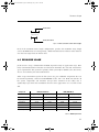
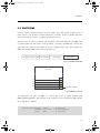
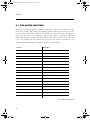
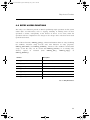
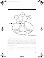
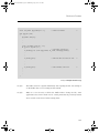
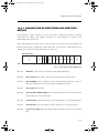
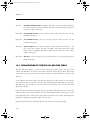
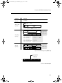
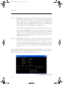
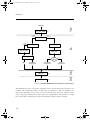
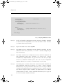
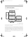
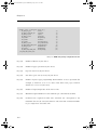
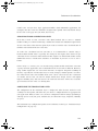
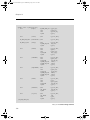
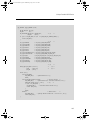
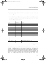
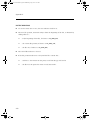
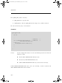
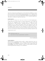
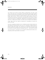
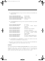
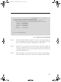
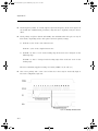
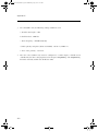
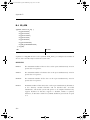
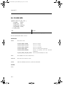
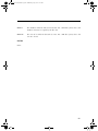
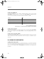
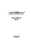
1-4 CHAPTER CONTENTS
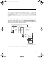
Figure 1-1 shows the layout and flow of the book. This diagram should be useful to
understand the relationship between chapters. The first (leftmost) column lists chapters that
should be read in order to understand μC/FS’s structure. The chapters in the second column
give greater detail about the application of μC/FS. Each of the chapters in the third column
examines a storage technology and its device driver. Finally, the fourth column lists the
appendices, the topmost being the μC/FS reference, configuration and porting manuals.
Reference these sections regularly when designing a product using μC/FS.
(A)
(1)
(B)
(2)
(C)
Introduction
µC/FS
Architecture
µC/FS Directories
and
Files
(3)
(4)
SD/MMC
Driver
Devices
and
Volumes
(5)
(6)
Files
(7)
Directories
(8)
POSIX
API
FAT
File System
Device
Drivers
(9)
µC/FS
Error
Codes
µC/FS
Porting
Manual
(11)
(D)
µC/FS
Types and
Structures
(12)
(E)
µC/FS
Configuration
Manual
(F)
µC/FS
Shell
Commands
RAM Disk
Driver
Useful Information
µC/FS API
Reference
Manual
(13)
NAND Flash
Driver
(14)
(10)
NOR Flash
Driver
Mass Storage
Class (MSC)
Driver
(15)
(G)
Bibliography
Figure 1-1 μC/FS book layout
18
600-uC-FS-002.book Page 19 Wednesday, July 3, 2013 1:26 PM
Chapter Contents
Chapter 1, “Introduction”. This chapter.
Chapter 2, “μC/FS Architecture”. This chapter contains a simplified block diagram of the
various different μC/FS modules and their relationships. The relationships are then
explained.
Chapter 3, “μC/FS Directories and Files”. This chapter explains the directory structure
and files needed to build a μC/FS-based application. Learn about the files that are needed,
where they should be placed, which module does what, and more.
Chapter 4, “Useful Information”. In this chapter, you will learn the nomenclature used
in μC/FS to access files and folders and the resources needed to use μC/FS in your
application.
Chapter 5, “Devices and Volumes”. Every file and directory accessed with μC/FS is a
constituent of a volume (a collection of files and directories) on a device (a physical or
logical sector-addressed entity). This chapter explains how devices and volumes are
managed.
Chapter 6, “Files”. μC/FS complements the POSIX API with its own file access API. This
chapter explains this API.
Chapter 7, “Directories”. μC/FS complements the POSIX API with its own directory
access API. This chapter explains this API.
Chapter 8, “POSIX API”. The best-known API for accessing and managing files and
directories is specified within the POSIX standard (IEEE Std 1003.1), which is based in part
in the ISO C standard (ISO/IEC 9899). This chapter explains how to use this API and
examines some of its pitfalls and shortcomings.
Chapter 10, “FAT File System”. This chapter details the low-level architecture of the FAT
file system. Though the API of μC/FS is file system agnostic, the file system type does affect
performance, reliability and security, as explained here as well.
Chapter 9, “Device Drivers”. All hardware accesses are eventually performed by a device
driver. This chapter describes the drivers available with μC/FS and broadly profiles
supported media types in terms of cost, performance and complexity.
19
600-uC-FS-002.book Page 20 Wednesday, July 3, 2013 1:26 PM
Chapter 1
Chapter 11, “RAM Disk Driver”. This chapter demonstrates the use of the simplest
storage medium, the RAM disk.
Chapter 12, “SD/MMC Drivers”. SD and MMC cards are flash-based removable storage
devices commonly used in consumer electronics. For embedded CPUs, a SD/MMC card is
an appealing medium because of its simple and widely-supported physical interfaces (one
choice is SPI). This chapter describes the interface and function of these devices.
Chapter 13, “NAND Flash Driver”. NAND flash is the first category of flash media. Write
speeds are fast (compared to NOR flash), at the expense of slower read speeds and
complexities such as bit-errors and page program limitations. This chapter describes the
functions of these devices and the architecture of the supporting driver.
Chapter 14, “NOR Flash Driver”. NOR flash is the second category of flash media. They
suffer slow write speeds, balanced with blazingly-fast read speeds. Importantly, they are not
plagued by the complications of NAND flash, which simplifies interfacing with them. This
chapter describes the function of these devices and the architecture of the supporting driver.
Chapter 15, “MSC Driver”. The now-common USB drive implements the Mass Storage
Class (MSC) protocol, and a CPU with a USB host interface can access these devices with
appropriate software. The MSC driver, discussed in this chapter, with μC/USB-Host is just
such appropriate software.
Appendix A, “μC/FS API Reference”. The reference manual describes every API
function. The arguments and return value of each function are given, supplemented by
notes about its use and an example code listing.
Appendix B, “μC/FS Error Codes”. This appendix provides a brief explanation of μC/FS
error codes defined in fs_err.h.
Appendix C, “μC/FS Porting Manual”. The portability of μC/FS relies upon ports to
interface between its modules and the platform or environment. Most of the ports constitute
the board support package (BSP), which is interposed between the file system suite (or
driver) and hardware. The OS port adapts the software to a particularly OS kernel. The
porting manual describes each port function.
Appendix D, “μC/FS Types and Structures”. This appendix provides a reference to the
μC/FS types and structures.
20
600-uC-FS-002.book Page 21 Wednesday, July 3, 2013 1:26 PM
Chapter Contents
Appendix E, “μC/FS Configuration”. μC/FS is configured via defines in a single
configuration file, fs_cfg.h. The configuration manual specifies each define and the
meaning of possible values.
Appendix F, “Shell Commands”. A familiar method of accessing a file system, at least to
engineers and computer scientists, is the command line. In an embedded system, a UART is
a port over which commands can be executed easily, even for debug purposes. A set of
shell commands have been developed for μC/FS that mirror the syntax of UNIX utilities, as
described in this chapter.
Appendix G, “Bibliography”.
Appendix H, “μC/FS Licensing Policy”.
21
600-uC-FS-002.book Page 22 Wednesday, July 3, 2013 1:26 PM
Chapter 1
22
600-uC-FS-002.book Page 23 Wednesday, July 3, 2013 1:26 PM
Chapter
2
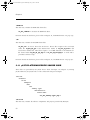
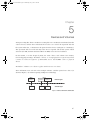
μC/FS Architecture
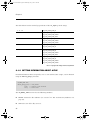
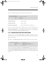
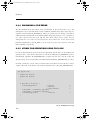
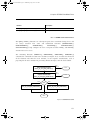
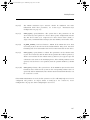
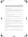
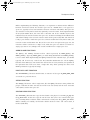
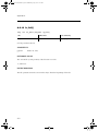
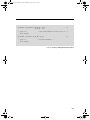
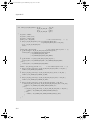
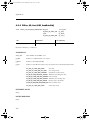
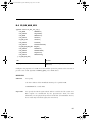
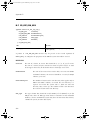
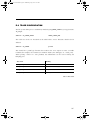
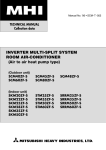
μC/FS was written from the ground up to be modular and easy to adapt to different CPUs
(Central Processing Units), RTOSs (Real-Time Operating Systems), storage media and
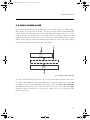
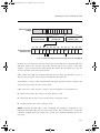
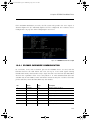
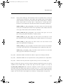
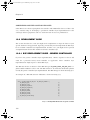
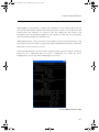
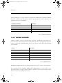
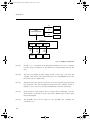
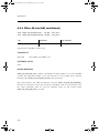
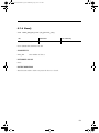
compilers. Figure 2-1 shows a simplified block diagram of the different μC/FS modules and
their relationships.
Notice that all of the μC/FS files start with ‘fs_’. This convention allows you to quickly
identify which files belong to μC/FS. Also note that all functions and global variables start
with ‘FS’, and all macros and #defines start with ‘FS_’.
23
600-uC-FS-002.book Page 24 Wednesday, July 3, 2013 1:26 PM
Chapter 2
<RXU$SSOLFDWLRQ
ȝ&/,%
OLEBGHIK
OLEBDVFLL
OLEBPHP
OLEBVWU
IVBFIJK
ȝ&)6
326,;$3,/D\HU
IVBDSL
)6/D\HU
IV
IVBGHY
IVBSDUWLWLRQ
IVBEXI
IVBGLU
IVBV\V
IVBFDFKH
IVBHQWU\
IVBW\SHK
IVBFIJBIVK
IVBHUUK
IVBXQLFRGH
IVBFWUK
IVBILOH
IVBXWLO
IVBGHIK
IVBLQFK
IVBYRO
)LOH6\VWHP'ULYHU/D\HU
ȝ&&5&
IVBIDW
IVBIDWBIDW
IVBIDWBVIQ
HGFBFUF
IVBIDWBGLU
IVBIDWBIDW
IVBIDWBW\SHK
HFFBKDPPLQJ
IVBIDWBHQWU\
IVBIDWBIDW
IVBIDWBMRXUQDO
HFFK
IVBIDWBILOH
IVBIDWBOIQ
FUFBXWLO
'HYLFH'ULYHU/D\HU
5$0'LVN
IVBGHYBUDP
ȝ&&38
FSXBDDVP
FSXK
FSXBGHIK
&38
6'00&
125
IVBGHYBVG
IVBGHYBVGBVSL
IVBGHYBVGBFDUG
IVBGHYBQRU
ȝ&&ON/D\HU
FON
7LPH
PDQDJHPHQW
,'(
IVBGHYBLGH
86%06&
IVBGHYBPVF
'HYLFH'ULYHU%63
5726/D\HU
IVBGHYBGULYHU!BEVSF
IVBRVFK
'HYLFH
5726
Figure 2-1 μC/FS architecture
24
600-uC-FS-002.book Page 25 Wednesday, July 3, 2013 1:26 PM
Architecture Components
2-1 ARCHITECTURE COMPONENTS
μC/FS consists of a set of modular software components. It also requires a few external
components (provided with the release) be compiled into the application and a few
configuration and BSP files be adapted to the application.
2-1-1 YOUR APPLICATION
Your application needs to provide configuration information to μC/FS in the form of one C
header file named fs_cfg.h.
Some of the configuration data in fs_cfg.h consist of specifying whether certain features
will be present. For example, LFN support, volume cache and file buffering are all enabled
or disabled in this file. In all, there are about 30 #define to set. However, most of these can
be set to their default values.
2-1-2 μC-LIB (LIBRARIES)
Because μC/FS is designed to be used in safety critical applications, all ‘standard’ library
functions like strcpy(), memset(), etc., have been re-written to follow the same quality as
the rest of the file system software.
2-1-3 POSIX API LAYER
Your application interfaces to μC/FS using the well-known stdio.h API (Application
Programming Interface). Alternately, you can use μC/FS’s own file and directory interface
functions. Basically, POSIX API layer is a layer of software that converts POSIX file access
calls to μC/FS file access calls.
25
600-uC-FS-002.book Page 26 Wednesday, July 3, 2013 1:26 PM
Chapter 2
2-1-4 FS LAYER
This layer contains most of the CPU-, RTOS- and compiler-independent code for μC/FS.
There are three categories of files in this section:
1
2
3
26
File system object-specific files:
■
Devices (fs_dev.*)
■
Directories (fs_dir.*)
■
Entries (fs_entry.*)
■
Files (fs_file.*)
■
Partitions (fs_partition.*)
■
Volumes (fs_vol.*)
Support files:
■
Buffer management (fs_buf.*)
■
Cache management (fs_cache.*)
■
Counter management (fs_ctr.h)
■
File system driver (fs_sys.*)
■
Unicode encoding support (fs_unicode.*)
■
Utility functions (fs_util.*)
Miscellaneous header files:
■
Master μC/FS header file (fs.h)
■
Error codes (fs_err.h)
■
Aggregate header file (fs_inc.h)
■
Miscellaneous data types (fs_type.h)
■
Miscellaneous definitions (fs_def.h)
■
Configuration definitions (fs_cfg_fs.h)
600-uC-FS-002.book Page 27 Wednesday, July 3, 2013 1:26 PM
Architecture Components
2-1-5 FILE SYSTEM DRIVER LAYER
The file system driver layer understands the organization of a particular file system type,
such as FAT. The current version of μC/FS only supports FAT file systems. fs_fat*.*
contains the file system driver which should be used for FAT12/FAT16/FAT32 disks with or
without Long File Name (LFN) support.
2-1-6 DEVICE DRIVER LAYER
The device driver layer understands about types of file system media (SD/MMC card, NOR
flash, etc.). In order for the device drivers to be independent of your CPU, we use additional
files to encapsulate such details as the access of registers, reading and writing to a data bus
and setting clock rates.
Each device driver is named according to the pattern
fs_dev_<dev drv name>.c
where <dev drv name> is the an identifier for the device driver. For example, the driver for
SD/MMC cards using SPI mode is called fs_dev_sd_spi.c. Most device drivers require a
BSP layer, with code for accessing registers, reading from or writing to a data bus, etc. This
file is named according to the pattern
fs_dev_<dev drv name>_bsp.c
For example, fs_dev_sd_spi_bsp.c contains the BSP functions for the driver SD/MMC
cards using SPI mode.
27
600-uC-FS-002.book Page 28 Wednesday, July 3, 2013 1:26 PM
Chapter 2
2-1-7 μC-CPU
μC/FS can work with either an 8, 16, 32 or even 64-bit CPU, but needs to have information
about the CPU you are using. The μC-CPU layer defines such things as the C data type
corresponding to 16-bit and 32-bit variables, whether the CPU is little- or big-endian and,
how interrupts are disabled and enabled on the CPU, etc.
CPU specific files are found in the …\uC-CPU directory and, in order to adapt μC/FS to a
different CPU, you would need to either modify the cpu*.* files or, create new ones based
on the ones supplied in the uC-CPU directory. In general, it’s much easier to modify existing
files because you have a better chance of not forgetting anything.
2-1-8 RTOS LAYER
μC/FS does not require an RTOS. However, if μC/FS is used with an RTOS, a set of functions
must be implemented to prevent simultaneous access of devices and core μC/FS structures
by multiple tasks.
μC/FS is provided with a no-RTOS (which contains just empty functions), a μC/OS-II and a
μC/OS-III interface. If you use a different RTOS, you can use the fs_os.* for μC/OS-II as a
template to interface to the RTOS of your choice.
28
600-uC-FS-002.book Page 29 Wednesday, July 3, 2013 1:26 PM
Chapter
3
μC/FS Directories and Files
μC/FS is fairly easy to use once you understand which source files are needed to make up a
μC/FS-based application. This chapter will discuss the modules available for μC/FS and how
everything fits together.
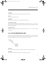
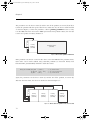
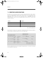
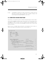
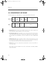
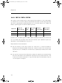
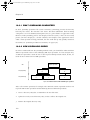
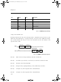
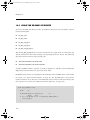
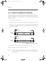
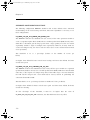
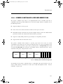
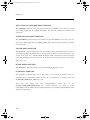
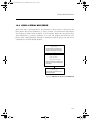
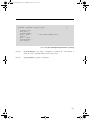
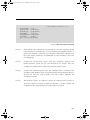
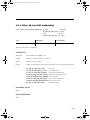
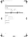
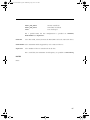
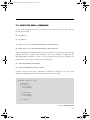
Figure 3-1 shows the μC/FS architecture and its relationship with the hardware. Memory
devices may include actual media both removable (SD/MMC, CF cards) and fixed (NAND
flash, NOR flash) as well as any controllers for such devices. Of course, your hardware
would most likely contain other devices such as UARTs (Universal Asynchronous Receiver
Transmitters), ADCs (Analog to Digital Converters) and Ethernet controller(s). Moreover,
your application may include other middleware components like an OS kernel, networking
(TCP/IP) stack or USB stack that may integrate with μC/FS.
A Windows™-based development platform is assumed. The directories and files make
references to typical Windows-type directory structures. However, since μC/FS is available
in source form then it can certainly be used on Unix, Linux or other development platforms.
This, of course, assumes that you are a valid μC/FS licensee in order to obtain the source
code.
The names of the files are shown in upper case to make them ‘stand out’. The file names,
however, are actually lower case.
29
600-uC-FS-002.book Page 30 Wednesday, July 3, 2013 1:26 PM
Chapter 3
(13)
μC/FS Configuration
(1)
Application Code
FS_CFG.H
APP.C/H
FS_APP.C/H
(8)
μC/FS
Platform Independent
FS.C/H
FS_API.C/H
FS_BUF.C/H
FS_CACHE.C/H
FS_CFG_FS.H
FS_CTR.H
FS_DEF.H
FS_DEV.C/H
FS_DIR.C/H
FS_ENTRY.C/H
(5)
μC/LIB
Libraries
FS_ERR.H
FS_FILE.C/H
FS_INC.H
FS_PARTITION.C/H
FS_SYS.C/H
FS_TYPE.H
FS_UNICODE.C/H
FS_UTIL.C/H
FS_VOL.C/H
LIB_ASCII.C/H
LIB_DEF.H
LIB_MATH.C/H
LIB_MEM.C/H
LIB_STR.C/H
(6)
μC/Clk
(9)
μC/FS
CLK.C/H
CLK_OS.C/H
Filesystem Driver
FS_FAT.C/H
FS_FAT_DIR.C/H
FS_FAT_ENTRY.C/H
FS_FAT_FAT12.C/H
FS_FAT_FAT16.C/H
FS_FAT_FAT32.C/H
FS_FAT_FILE.C/H
FS_FAT_JOURNAL.C/H
FS_FAT_LFN.C/H
FS_FAT_SFN.C/H
FS_FAT_TYPE.H
(7)
ECC.H
EDC_CRC.C/H
ECC_HAMMING.C/H
CRC_UTIL.C/H
(10)
μC/FS
(11)
μC/FS
μC/CRC
μC/FS
(12)
Device Drivers
OS Specific
FS_DEV_*.C/H
FS_OS.C/H
(4)
(3)
μC/CPU
BSP
Platform Specific
CPU Specific
Board Support Package
FS_DEV_*_BSP.C
CPU.H
CPU_A.ASM
CPU_CORE.C/H
BSP.C/H
(2)
CPU
*.C
*.H
Software / Firmware
Hardware
Memory
Devices
CPU
Interrupt
Controller
Figure 3-1 μC/FS Architecture
F3-1(1)
30
The application code consist of project or product files. For convenience, we
simply called these app.c and app.h but your application can contain any
number of files and they do not have to be called app.*. The application code
is typically where you would find main().
600-uC-FS-002.book Page 31 Wednesday, July 3, 2013 1:26 PM
F3-1(2)
Quite often, semiconductor manufacturers provide library functions in source
form for accessing the peripherals on their CPU (Central Processing Unit) or
MCU (Micro Controller Unit). These libraries are quite useful and often save
valuable time. Since there is no naming convention for these files, *.c and *.h
are assumed.
F3-1(3)
The Board Support Package (BSP) is code that you would typically write to
interface to peripherals on your target board. For example you can have code
to turn on and off LEDs (light emitting diodes), functions to turn on and off
relays, and code to read switches and temperature sensors.
F3-1(4)
μC/CPU is an abstraction of basic CPU-specific functionality. These files define
functions to disable and enable interrupts, data types (e.g., CPU_INT08U,
CPU_FP32) independent of the CPU and compiler and many more functions.
F3-1(5)
μC/LIB consists of a group of source files to provide common functions for
memory copy, string manipulation and character mapping. Some of the
functions replace stdlib functions provided by the compiler. These are provided
to ensure that they are fully portable from application to application and (most
importantly) from compiler to compiler.
F3-1(6)
μC/Clk is an independant clock/calendar management module, with source
code for easily managing date and time in a product. μC/FS uses the date and
time information from μC/Clk to update files and directories with the proper
creation/modification/access time.
F3-1(7)
μC/CRC is a stand-alone module for calculating checksums and error correction
codes. This module is used by some of μC/FS device drivers.
F3-1(8)
This is the μC/FS platform-independent code, free of dependencies on CPU
and memory device. This code is written in highly-portable ANSI C code. This
code is only available to μC/FS licensees.
F3-1(9)
This is the μC/FS system driver for FAT file systems. This code is only available
to μC/FS licensees.
31
600-uC-FS-002.book Page 32 Wednesday, July 3, 2013 1:26 PM
Chapter 3
F3-1(10)
This is the collection of device drivers for μC/FS. Each driver supports a certain
device type, such as SD/MMC cards, NAND flash or NOR flash. Drivers are only
available to μC/FS licensees.
F3-1(11)
This is the μC/FS code that is adapted to a specific platform. It consists of small
code modules written for specific drivers called ports that must be adapted to
the memory device controllers or peripherals integrated into or attached to the
CPU. The requirements for these ports are described in Appendix C, Porting
Manual.
F3-1(12)
μC/FS does not require an RTOS. However, if μC/FS is used with an RTOS, a
set of functions must be implemented to prevent simultaneous access of
devices and core μC/FS structures by multiple tasks.
F3-1(13)
This μC/FS configuration file defines which μC/FS features (fs_cfg.h) are
included in the application.
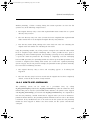
3-1 APPLICATION CODE
When Micriμm provides you with example projects, we typically place those in a directory
structure as shown below. Of course, you can use whatever directory structure suits your
project/product.
\Micrium
\Software
\EvalBoards
\<manufacturer>
\<board name>
\<compiler>
\<project name>
\*.*
\Micrium
This is where we place all software components and projects provided by Micriμm. This
directory generally starts from the root directory of your computer.
32
600-uC-FS-002.book Page 33 Wednesday, July 3, 2013 1:26 PM
Application Code
\Software
This sub-directory contains all the software components and projects.
\EvalBoards
This sub-directory contains all the projects related to the evaluation boards supported by
Micriμm.
\<manufacturer>
Is the name of the manufacturer of the evaluation board. The ‘<’ and ‘>’ are not part of the
actual name.
\<board name>
This is the name of the evaluation board. A board from Micriμm will typically be called
uC-Eval-xxxx where ‘xxxx’ will represent the CPU or MCU used on the evaluation board.
The ‘<’ and ‘>’ are not part of the actual name.
\<compiler>
This is the name of the compiler or compiler manufacturer used to build the code for the
evaluation board. The ‘<’ and ‘>’ are not part of the actual name.
\<project name>
This is the name of the project that will be demonstrated. For example a simple μC/FS
project might have a project name of ‘FS-Ex1’. The ‘-Ex1’ represents a project containing
only μC/FS. A project name of FS-Probe-Ex1 would represent a project containing μC/FS as
well as μC/Probe. The ‘<’ and ‘>’ are not part of the actual name.
\*.*
These are the source files for the project/product. You are certainly welcomed to call the
main files APP*.* for your own projects but you don’t have to. This directory also contains
the configuration file FS_CFG.H and other files as needed by the project.
33
600-uC-FS-002.book Page 34 Wednesday, July 3, 2013 1:26 PM
Chapter 3
3-2 CPU
As shown below is the directory where we place semiconductor manufacturer peripheral
interface source files. Of course, you can use whatever directory structure suits your
project/product.
\Micrium
\Software
\CPU
\<manufacturer>
\<architecture>
\*.*
\Micrium
This is where we place all software components and projects provided by Micriμm.
\Software
This sub-directory contains all the software components and projects.
\CPU
This sub-directory is always called CPU.
\<manufacturer>
Is the name of the semiconductor manufacturer who provided the peripheral library. The ‘<’
and ‘>’ are not part of the actual name.
\<architecture>
This is the name of the specific library and is generally associated with a CPU name or an
architecture.
\*.*
These are the library source files. The names of the files are determined by the
semiconductor manufacturer.
34
600-uC-FS-002.book Page 35 Wednesday, July 3, 2013 1:26 PM
Board Support Package (BSP)
3-3 BOARD SUPPORT PACKAGE (BSP)
The BSP is generally found with the evaluation or target board because the BSP is specific
to that board. In fact, if well written, the BSP should be used for multiple projects.
\Micrium
\Software
\EvalBoards
\<manufacturer>
\<board name>
\<compiler>
\BSP
\*.*
\Micrium
This is where we place all software components and projects provided by Micriμm.
\Software
This sub-directory contains all the software components and projects.
\EvalBoards
This sub-directory contains all the projects related to evaluation boards.
\<manufacturer>
Is the name of the manufacturer of the evaluation board. The ‘<’ and ‘>’ are not part of the
actual name.
\<board name>
This is the name of the evaluation board. A board from Micriμm will typically be called uC
Eval xxxx where ‘xxxx’ will be the name of the CPU or MCU used on the evaluation board.
The ‘<’ and ‘>’ are not part of the actual name.
\<compiler>
This is the name of the compiler or compiler manufacturer used to build the code for the
evaluation board. The ‘<’ and ‘>’ are not part of the actual name.
35
600-uC-FS-002.book Page 36 Wednesday, July 3, 2013 1:26 PM
Chapter 3
\BSP
This directory is always called BSP.
\*.*
These are the source files of the BSP. Typically all the file names start with BSP_ but they
don’t have to. It’s thus typical to find bsp.c and bsp.h in this directory. Again, the BSP code
should contain functions such as LED control functions, initialization of timers, interface to
Ethernet controllers and more.
3-4 μC/CPU, CPU SPECIFIC SOURCE CODE
μC/CPU consists of files that encapsulate common CPU-specific functionality as well as
CPU- and compiler-specific data types.
\Micrium
\Software
\uC-CPU
\cpu_core.c
\cpu_core.h
\cpu_def.h
\Cfg\Template
\cpu_cfg.h
\<architecture>
\<compiler>
\cpu.h
\cpu_a.asm
\cpu_c.c
\Micrium
This directory contains all software components and projects provided by Micriμm.
\Software
This sub-directory contains all the software components and projects.
36
600-uC-FS-002.book Page 37 Wednesday, July 3, 2013 1:26 PM
μC/CPU, CPU Specific Source Code
\uC-CPU
This is the main μC/CPU directory.
cpu_core.c contains C code that is common to all CPU architectures. Specifically, this
file contains functions to measure the interrupt disable time of the
CPU_CRITICAL_ENTER() and CPU_CRITICAL_EXIT() macros, a function that emulates a
count leading zeros instruction and a few other functions.
cpu_core.h contains the function prototypes of the functions provided in cpu_core.c
as well as allocation of the variables used by this module to measure interrupt disable
time.
cpu_def.h contains miscellaneous #define constants used by the μC/CPU module.
\Cfg\Template
This directory contains a configuration template file (cpu_cfg.h) that you will need to copy
to your application directory in order to configure the μC/CPU module based on your
application requirements.
cpu_cfg.h determines whether you will enable measurement of the interrupt disable
time, whether your CPU implements a count leading zeros instruction in assembly
language or whether it will need to be emulated in C and more.
\<architecture>
This is the name of the CPU architecture for which μC/CPU was ported to. The ‘<’ and ‘>’
are not part of the actual name.
\<compiler>
This is the name of the compiler or compiler manufacturer used to build the code for the
μC/CPU port. The ‘<’ and ‘>’ are not part of the actual name.
The files in this directory contain the μC/CPU port.
cpu.h contains type definitions to make μC/FS and other modules independent of the
CPU and compiler word sizes. Specifically, you will find the declaration of the
CPU_INT16U, CPU_INT32U, CPU_FP32 and many other data types. Also, this file specifies
whether the CPU is a big- or little-endian machine and contains function prototypes for
functions that are specific to the CPU architecture and more.
37
600-uC-FS-002.book Page 38 Wednesday, July 3, 2013 1:26 PM
Chapter 3
cpu_a.asm contains the assembly language functions to implement the code to disable
and enable CPU interrupts, count leading zeros (if the CPU supports that instruction)
and other CPU specific functions that can only be written in assembly language. This
file could also contain code to enable caches, setup MPUs and MMU and more. The
functions provided in this file are accessible from C.
cpu_c.c contains C code of functions that are specific to the specific CPU architecture
but written in C for portability. As a general rule, if a function can be written in C then
it should, unless there are significant performance benefits by writing it in assembly
language.
3-5 μC/LIB, PORTABLE LIBRARY FUNCTIONS
μC/LIB consists of library functions that are meant to be highly portable and not tied to any
specific compiler. This was done to facilitate third party certification of Micriμm products.
\Micrium
\Software
\uC-LIB
\lib_ascii.c
\lib_ascii.h
\lib_def.h
\lib_math.c
\lib_math.h
\lib_mem.c
\lib_mem.h
\lib_str.c
\lib_str.h
\Cfg\Template
\lib_cfg.h
\Ports
\<architecture>
\<compiler>
\lib_mem_a.asm
\Micrium
This directory contains all software components and projects provided by Micriμm.
38
600-uC-FS-002.book Page 39 Wednesday, July 3, 2013 1:26 PM
μC/Clk, Time/Calendar Management
\Software
This sub-directory contains all the software components and projects.
\uC-LIB
This is the main μC/LIB directory.
\Cfg\Template
This directory contains a configuration template file (lib_cfg.h) that must be copied to the
application directory to configure the μC/LIB module based on application requirements.
lib_cfg.h determines whether to enable assembly-language optimization (assuming
there is an assembly-language file for the processor, i.e. lib_mem_a.asm) and a few
other #defines.
3-6 μC/CLK, TIME/CALENDAR MANAGEMENT
μC/Clk consists of functions that are meant to centralize time management in one
independant module. This way, the same time info can be easily shared across all Micrium
products.
\Micrium
\Software
\uC-Clk
\Cfg
\Template
\clk_cfg.h
\OS
\<rtos_name>
\clk_os.c
\Source
\clk.c
\clk.h
\Micrium
This directory contains all software components and projects provided by Micriμm.
39
600-uC-FS-002.book Page 40 Wednesday, July 3, 2013 1:26 PM
Chapter 3
\Software
This sub-directory contains all the software components and projects.
\uC-Clk
This is the main μC/Clk directory.
\Cfg\Template
This directory contains a configuration template file (clk_cfg.h) that must be copied to the
application directory to configure the μC/Clk module based on application requirements.
clk_cfg.h determines whether clock will be managed by the RTOS or in your
application. A few other #defines are used to enable/disable some features of μC/Clk
and to configure some parameteres, like the clock frequency.
\OS
This is the main OS directory.
\<rtos_name>
This is the directory that contains the file to perform RTOS abstraction. Note that the file for
the selected RTOS abstraction layer must always be named clk_os.c.
μC/Clk has been tested with μC/OS-II, μC/OS-III and the RTOS layer files for these RTOS
are found in the following directories:
\Micrium\Software\uC-Clk\OS\uCOS-II\clk_os.c
\Micrium\Software\uC-Clk\OS\uCOS-III\clk_os.c
\Source
This directory contains the CPU-independant source code for μC/Clk. All file in this
directory should be included in the build (assuming the presence of the source code).
Features that are not required will be compiled out based on the value of #define constants
in clk_cfg.h.
40
600-uC-FS-002.book Page 41 Wednesday, July 3, 2013 1:26 PM
μC/CRC, Checksums and Error Correction Codes
3-7 μC/CRC, CHECKSUMS AND ERROR CORRECTION CODES
μC/CRC consists of functions to compute different error detection and correction codes. The
functions are speed-optimized to avoid the important impact on performances that these
CPU-intensive calcutions may present.
\Micrium
\Software
\uC-CRC
\Cfg
\Template
\crc_cfg.h
\Ports
\<architecture>
\<compiler>
\ecc_hamming_a.asm
\edc_crc_a.asm
\Source
\edc_crc.h
\edc_crc.c
\ecc_hamming.h
\ecc_hamming.c
\ecc.h
\crc_util.h
\crc_util.c
\Micrium
This directory contains all software components and projects provided by Micriμm.
\Software
This sub-directory contains all the software components and projects.
\uC-CRC
This is the main μC/CRC directory.
41
600-uC-FS-002.book Page 42 Wednesday, July 3, 2013 1:26 PM
Chapter 3
\Cfg\Template
This directory contains a configuration template file (crc_cfg.h) that must be copied to the
application directory to configure the μC/CRC module based on application requirements.
crc_cfg.h determines whether to enable assembly-language optimization (assuming
there is an assembly-language file for the processor) and a few other #defines.
\<architecture>
The name of the CPU architecture that μC/CRC was ported to. The ‘<’ and ‘>’ are not part of
the actual name.
\<compiler>
The name of the compiler or compiler manufacturer used to build code for the μC/CRC
port. The ‘<’ and ‘>’ are not part of the actual name.
ecc_hamming_a.asm contains the assembly language functions to optimize the
calculation speed of Hamming code.
edc_crc_a.asm contains the assembly language functions to optimize the calculation
speed of CRC (cyclic redundancy checks).
\Source
This is the directory that contains all the CPU independent source code files. of μC/CRC.
3-8 μC/FS PLATFORM-INDEPENDENT SOURCE CODE
The files in these directories are available to μC/FS licensees (see Appendix H, Licensing
Policy).
\Micrium
\Software
\uC-FS
\APP\Template
\fs_app.c
\fs_app.h
\Cfg\Template
\fs_cfg.h
42
600-uC-FS-002.book Page 43 Wednesday, July 3, 2013 1:26 PM
μC/FS Platform-Independent Source Code
\OS\Template
\fs_os.c
\fs_os.h
\Source
\fs_c
\fs.h
\fs_api.c
\fs_api.h
\fs_buf.c
\fs_buf.h
\fs_cache.c
\fs_cache.h
\fs_cfg_fs.h
\fs_ctr.h
\fs_def.h
\fs_dev.c
\fs_dev.h
\fs_dir.c
\fs_dir.h
\fs_entry.c
\fs_entry.h
\fs_err.h
\fs_file.c
\fs_file.h
\fs_inc.h
\fs_partition.c
\fs_partition.h
\fs_sys.c
\fs_sys.h
\fs_type.h
\fs_unicode.c
\fs_unicode.h
\fs_util.c
\fs_util.h
\fs_vol.c
\fs_vol.h
43
600-uC-FS-002.book Page 44 Wednesday, July 3, 2013 1:26 PM
Chapter 3
\Micrium
This is where we place all software components and projects provided by Micriμm.
\Software
This sub-directory contains all the software components and projects.
\uC-FS
This is the main μC/FS directory.
\APP\Template
This directory contains a template of the code for initializing the file system.
\Cfg\Template
This directory contains a configuration template file (lib_cfg.h) that is required to be
copied to the application directory to configure the μC/FS module based on application
requirements.
fs_cfg.h specifies which features of μC/FS you want in your application. If μC/FS is
provided in linkable object code format then this file will be provided to show you what
features are available in the object file. See Appendix B, μC/FS Configuration Manual.
\Source
This directory contains the platform-independent source code for μC/FS. All the files in this
directory should be included in your build (assuming you have the source code). Features
that you don’t want will be compiled out based on the value of #define constants in
fs_cfg.h.
fs.c/h contains core functionality for μC/FS including FS_Init() (called to initialize
μC/FS) and FS_WorkingDirSet()/FS_WorkingDirGet() (used to get and set the
working directory).
fs_api.c/h contains the code for the POSIX-compatible API. See Chapter x, API for
details about the POSIX-compatible API.
fs_buf.c/h contains the code for the buffer management (used internally by μC/FS).
fs_dev.c/h contains code for device management. See Chapter x, Devices for details
about devices.
44
600-uC-FS-002.book Page 45 Wednesday, July 3, 2013 1:26 PM
μC/FS FAT Filesystem Source Code
fs_dir.c/h contains code for directory access. See Chapter x, Directories for details
about directory access.
fs_entry.c/h contains code for entry access. See Chapter x, Entries for details about
entry access.
fs_file.c/h contains code for file access. See Chapter x, Files for details about file
access.
fs_inc.h is a master include file that includes all
fs_sys.c/h contains the code for system driver management (used internally by
μC/FS).
fs_unicode.c/h contains the code for handling Unicode strings (used internally by
μC/FS).
3-9 μC/FS FAT FILESYSTEM SOURCE CODE
The files in these directories are available to μC/FS licensees (see Appendix H, Licensing
Policy).
\Micrium
\Software
\uC-FS
\FAT
\fs_fat.c
\fs_fat.h
\fs_fat_dir.c
\fs_fat_dir.h
\fs_fat_entry.c
\fs_fat_entry.h
\fs_fat_fat12.c
\fs_fat_fat12.h
\fs_fat_fat16.c
\fs_fat_fat16.h
\fs_fat_fat32.c
45
600-uC-FS-002.book Page 46 Wednesday, July 3, 2013 1:26 PM
Chapter 3
\fs_fat_fat32.h
\fs_fat_file.c
\fs_fat_file.h
\fs_fat_journal.c
\fs_fat_journal.h
\fs_fat_lfn.c
\fs_fat_lfn.h
\fs_fat_sfn.c
\fs_fat_sfn.h
\fs_fat_type.h
\Micrium
This is where we place all software components and projects provided by Micriμm.
\Software
This sub-directory contains all the software components and projects.
\uC-FS
This is the main μC/FS directory.
\FAT
This directory contains the FAT system driver for μC/FS. All the files in this directory should
be included in your build (assuming you have the source code).
3-10 μC/FS MEMORY DEVICE DRIVERS
These files are generic drivers to use with differenty memory devices.
\Micrium
\Software
\uC-FS
\Dev
\MSC
\fs_dev_msc.c
\fs_dev_msc.h
\NAND
\fs_dev_nand.c
46
600-uC-FS-002.book Page 47 Wednesday, July 3, 2013 1:26 PM
μC/FS Memory Device Drivers
\fs_dev_nand.h
\Ctrlr
\fs_dev_nand_ctrlr_gen.c
\fs_dev_nand_ctrlr_gen.h
\fs_dev_nand_ctrlr_gen_soft_ecc.c
\fs_dev_nand_ctrlr_gen_soft_ecc.h
\fs_dev_nand_ctrlr_gen_micron_ecc.c
\fs_dev_nand_ctrlr_gen_micron_ecc.h
\Part
\fs_dev_nand_part_static.c
\fs_dev_nand_part_static.h
\fs_dev_nand_part_onfi.c
\fs_dev_nand_part_onfi.h
\Cfg\Template
fs_dev_nand_cfg.h
\BSP\Template
\fs_dev_nand_ctrlr_gen_bsp.c
\NOR
\fs_dev_nor.c
\fs_dev_nor.h
\PHY
\fs_dev_nor_amd_1x08.c
\fs_dev_nor_amd_1x08.h
\fs_dev_nor_amd_1x16.c
\fs_dev_nor_amd_1x16.h
\fs_dev_nor_intel.c
\fs_dev_nor_intel.h
\fs_dev_nor_sst25.c
\fs_dev_nor_sst25.h
\fs_dev_nor_sst39.c
\fs_dev_nor_sst39.h
\fs_dev_nor_stm25.c
\fs_dev_nor_stm25.h
\fs_dev_nor_stm29_1x08.c
\fs_dev_nor_stm29_1x08.h
\fs_dev_nor_stm29_1x16.c
\fs_dev_nor_stm29_1x16.h
\Template
47
600-uC-FS-002.book Page 48 Wednesday, July 3, 2013 1:26 PM
Chapter 3
\fs_dev_nor_template.c
\fs_dev_nor_template.h
\BSP\Template
\fs_dev_nor_bsp.c
\BSP\Template (SPI GPIO)
\fs_dev_nor_bsp.c
\BSP\Template (SPI)
\fs_dev_nor_bsp.c
\RAMDisk
\fs_dev_ram.c
\fs_dev_ram.h
\SD
\fs_dev_sd.c
\fs_dev_sd.h
\Card
\fs_dev_sd_card.c
\fs_dev_sd_card.h
\BSP\Template
\fs_dev_sd_card_bsp.c
\SPI
\fs_dev_sd_spi.c
\fs_dev_sd_spi.h
\BSP\Template
\fs_dev_sd_spi.bsp.c
\Template
\fs_dev_template.c
\fs_dev_template.h
\Micrium
This directory contains all software components and projects provided by Micriμm.
\Software
This sub-directory contains all the software components and projects.
\uC-FS
This is the main μC/FS directory.
48
600-uC-FS-002.book Page 49 Wednesday, July 3, 2013 1:26 PM
μC/FS Memory Device Drivers
\Dev
This is where you will find the device driver files for the storage devices you are planning
on using.
\MSC
This directory contains the MSC (Mass Storage Class - USB drives) driver files.
fs_dev_msc.* are device driver for MSC devices. This driver is designed to work with
μC/USB host stack.
For more details on this driver, please refer to Chapter 15, “MSC Driver” on page 219.
\NAND
This directory contains the NAND driver files.
fs_dev_nand.* are the device driver for NAND devices. These files require a set of
controller-layer functions (defined in a file named fs_dev_nand_ctrlr_<type>.*) as
well as BSP functions specific to particular hardware and associated with chosen
controller-layer (to be defined in a file named fs_dev_nand_ctrlr_<type>_bsp.c).
Note that in the case of the “generic” controller-layer implementation, some controller
extensions files (defined in files named fs_dev_nand_ctrlr_<ext_name>.*) may also
be required.
For more details on this driver, please refer to Chapter 13, “NAND Flash Driver” on
page 161.
\NOR
This directory contains the NOR driver files.
fs_dev_nor.* are the device driver for NOR devices. These files require a set of
physical-layer functions (defined in a file name fs_dev_nor_<physical type>.*) as
well as BSP functions (to be defined in a file named fs_dev_nor_bsp.c) to work with
a particular hardware setup.
For more details on this driver, please refer to Chapter 14, “NOR Flash Driver” on page 199.
49
600-uC-FS-002.book Page 50 Wednesday, July 3, 2013 1:26 PM
Chapter 3
\RAMDisk
This directory contains the RAM disk driver files.
fs_dev_ramdisk.* constitue the RAM disk driver.
For more details on this driver, please refer to Chapter 11, “RAM Disk Driver” on page 133.
\SD
This directory contains the SD/MMC driver files.
fs_dev_sd.* are device driver for SD devices. Theses files require to be used with
either the fs_dev_sd_spi.* (for SPI/one-wire mode) or fs_dev_sd_card.* (for
Card/4-wires mode) files. These files require a set of BSP functions to be defined in a
file named either fs_dev_sd_spi_bsp.c or fs_dev_sd_card_bsp.c to work with a
particular hardware setup.
For more details on this driver, please refer to Chapter 12, “SD/MMC Drivers” on page 137.
3-11 μC/FS PLATFORM-SPECIFIC SOURCE CODE
These files are provided by the μC/FS device driver developer. See Chapter 17, Porting
μC/FS. However, the μC/FS source code is delivered with port examples.
\Micrium
\Software
\uC-FS
\Examples
\BSP
\Dev
<memory type>
<manufacturer>
<board name>
\fs_dev_<memory type>_bsp.c
\Micrium
This directory contains all software components and projects provided by Micriμm.
50
600-uC-FS-002.book Page 51 Wednesday, July 3, 2013 1:26 PM
μC/FS OS Abstraction Layer
\Software
This sub-directory contains all the software components and projects.
\uC-FS
This is the main μC/FS directory.
\Examples
This is where you will find the device driver BSP example files.
\Dev\<memory type>
This is where you will find the examples BSP for one memory type. The ‘<’ and ‘>’ are not
part of the actual name. The memory types supported by μC/FS are the following: NAND,
NOR, SD\CARD, SD\SPI.
\<manufacturer>
The name of the manufacturer of the evaluation board. The ‘<’ and ‘>’ are not part of the
actual name.
3-12 μC/FS OS ABSTRACTION LAYER
This directory contains the RTOS abstraction layer which allows the use of μC/FS with
nearly any commercial of in-house RTOS, or without any RTOS at all. The abstraction layer
for the selected RTOS is placed in a sub-directory under OS as follows:
\Micrium
\Software
\uC-FS
\OS
\<rtos_name>
\fs_os.c
\fs_os.h
\Micrium
This directory contains all software components and projects provided by Micriμm.
\Software
This sub-directory contains all the software components and projects.
51
600-uC-FS-002.book Page 52 Wednesday, July 3, 2013 1:26 PM
Chapter 3
\uC-FS
This is the main μC/FS directory.
\OS
This is the main OS directory.
\<rtos_name>
This is the directory that contains the files to perform RTOS abstraction. Note that files for
the selected RTOS abstraction layer must always be named fs_os.*.
μC/FS has been tested with μC/OS-II, μC/OS-III and without an RTOS. The RTOS layer files
are found in the following directories:
\Micrium\Software\uC-Clk\OS\None\fs_os.*
\Micrium\Software\uC-Clk\OS\Template\fs_os.*
\Micrium\Software\uC-Clk\OS\uCOS-II\fs_os.*
\Micrium\Software\uC-Clk\OS\uCOS-III\fs_os.*
3-13 SUMMARY
Below is a summary of all the directories and files involved in a μC/FS-based project. The
‘<-Cfg’ on the far right indicates that these files are typically copied into the application
(i.e., project) directory and edited based on project requirements.
\Micrium
\Software
\EvalBoards
\<manufacturer>
\<board name>
\<compiler>
\<project name>
\app.c
\app.h
\other
\BSP
\bsp.c
\bsp.h
52
600-uC-FS-002.book Page 53 Wednesday, July 3, 2013 1:26 PM
Summary
\other
\CPU
\<manufacturer>
\<architecture>
\*.*
\uC-FS
\APP\Template
\fs_app.c
<-Cfg
\fs_app.h
<-Cfg
\CFG\Template
\fs_cfg.h
<-Cfg
\Dev
\MSC
\fs_dev_msc.c
\fs_dev_msc.h
\NAND
\fs_dev_nand.c
\fs_dev_nand.h
\Ctrlr
\fs_dev_nand_ctrlr_gen.c
\fs_dev_nand_ctrlr_gen.h
\fs_dev_nand_ctrlr_gen_soft_ecc.c
\fs_dev_nand_ctrlr_gen_soft_ecc.h
\fs_dev_nand_ctrlr_gen_micron_ecc.c
\fs_dev_nand_ctrlr_gen_micron_ecc.h
\Part
\fs_dev_nand_part_static.c
\fs_dev_nand_part_static.h
\fs_dev_nand_part_onfi.c
\fs_dev_nand_part_onfi.h
\Cfg\Template
fs_dev_nand_cfg.h
\BSP\Template
\fs_dev_nand_ctrlr_gen_bsp.c
\NOR
\fs_dev_nor.c
\fs_dev_nor.h
\PHY
53
600-uC-FS-002.book Page 54 Wednesday, July 3, 2013 1:26 PM
Chapter 3
\fs_dev_nor_amd_1x08.c
\fs_dev_nor_amd_1x08.h
\fs_dev_nor_amd_1x16.c
\fs_dev_nor_amd_1x16.h
\fs_dev_nor_intel.c
\fs_dev_nor_intel.h
\fs_dev_nor_sst25.c
\fs_dev_nor_sst25.h
\fs_dev_nor_sst39.c
\fs_dev_nor_sst39.h
\fs_dev_nor_stm25.c
\fs_dev_nor_stm25.h
\fs_dev_nor_stm29_1x08.c
\fs_dev_nor_stm29_1x08.h
\fs_dev_nor_stm29_1x16.c
\fs_dev_nor_stm29_1x16.h
\Template
\fs_dev_nor_template.c
\fs_dev_nor_template.h
\BSP\<template>
\fs_dev_nor_bsp.c
\RAMDisk
\fs_dev_ram.c
\fs_dev_ram.h
\SD
\fs_dev_sd.c
\fs_dev_sd.h
\Card
\fs_dev_sd_card.c
\fs_dev_sd_card.h
\BSP\Template
\fs_dev_sd_card_bsp.c
\SPI
\fs_dev_sd_spi.c
\fs_dev_sd_spi.h
\BSP\Template
\fs_dev_sd_spi.bsp.c
\Template
54
<-Cfg
<-Cfg
<-Cfg
<-Cfg
<-Cfg
600-uC-FS-002.book Page 55 Wednesday, July 3, 2013 1:26 PM
Summary
\fs_dev_template.c
\fs_dev_template.h
\FAT
\fs_fat.c
\fs_fat.h
\fs_fat_dir.c
\fs_fat_dir.h
\fs_fat_entry.c
\fs_fat_entry.h
\fs_fat_fat12.c
\fs_fat_fat12.h
\fs_fat_fat16.c
\fs_fat_fat16.h
\fs_fat_fat32.c
\fs_fat_fat32.h
\fs_fat_file.c
\fs_fat_file.h
\fs_fat_journal.c
\fs_fat_journal.h
\fs_fat_lfn.c
\fs_fat_lfn.h
\fs_fat_sfn.c
\fs_fat_sfn.h
\fs_fat_type.h
\OS
\<template>
\fs_os.c
\fs_os.h
\<rtos_name>
\fs_os.c
\fs_os.h
\Source
\fs_c
\fs.h
\fs_api.c
\fs_api.h
\fs_buf.c
\fs_buf.h
<-Cfg
<-Cfg
<-Cfg
<-Cfg
55
600-uC-FS-002.book Page 56 Wednesday, July 3, 2013 1:26 PM
Chapter 3
\fs_cache.c
\fs_cache.h
\fs_cfg_fs.h
\fs_ctr.h
\fs_def.h
\fs_dev.c
\fs_dev.h
\fs_dir.c
\fs_dir.h
\fs_entry.c
\fs_entry.h
\fs_err.h
\fs_file.c
\fs_file.h
\fs_inc.h
\fs_partition.c
\fs_partition.h
\fs_sys.c
\fs_sys.h
\fs_type.h
\fs_unicode.c
\fs_unicode.h
\fs_util.c
\fs_util.h
\fs_vol.c
\fs_vol.h
\OS
\<architecture>
\<compiler>
\os_cpu.h
\os_cpu_a.asm
\os_cpu_c.c
\uC-CPU
\cpu_core.c
\cpu_core.h
\cpu_def.h
\Cfg\Template
\cpu_cfg.h
56
<-Cfg
600-uC-FS-002.book Page 57 Wednesday, July 3, 2013 1:26 PM
Summary
\<architecture>
\<compiler>
\cpu.h
\cpu_a.asm
\cpu_c.c
\uC-Clk
\Cfg
\Template
\clk_cfg.h
\OS
\<rtos_name>
\clk_os.c
\Source
\clk.c
\clk.h
\uC-CRC
\Cfg
\Template
\crc_cfg.h
\Ports
\<architecture>
\<compiler>
\ecc_hamming_a.asm
\edc_crc_a.asm
\Source
\edc_crc.h
\edc_crc.c
\ecc_hamming.h
\ecc_hamming.c
\ecc.h
\uC-LIB
\lib_ascii.c
\lib_ascii.h
\lib_def.h
\lib_math.c
\lib_math.h
\lib_mem.c
\lib_mem.h
<-Cfg
<-Cfg
57
600-uC-FS-002.book Page 58 Wednesday, July 3, 2013 1:26 PM
Chapter 3
\lib_str.c
\lib_str.h
\Cfg\Template
\lib_cfg.h
58
<-Cfg
600-uC-FS-002.book Page 59 Wednesday, July 3, 2013 1:26 PM
Chapter
4
Useful Information
4-1 NOMENCLATURE
This manual uses a set of terms to consistently describe operation of μC/FS and its hardware
and software environment. The following is a small list of these terms, with definitions.
A file system suite is software which can find and access files and directories. Using “file
system suite” rather than “file system” eliminates any need for disambiguation among the
second term’s several meanings, which include “a system for organizing directories and
files”, “a collection of files and directories stored on a drive” and (commonly) the software
which will be referred to as a file system suite. The term file system will always mean a
collection of files and directories stored on a drive (or, in this document, volume).
A device driver (or just driver) is a code module which allows the general-purpose file
system suite to access a specific type of device. A device driver is registered with the file
system suite.
A device is an instance of a device type that is accessed using a device driver. An
addressable area (typically of 512 bytes) on a device is a sector. A sector is the smallest area
that (from the file system suite’s point of view) can be atomically read or written.
Several devices can use the same device driver. These are distinguished by each having a
unique unit number. Consequently, <DEVICE NAME>:<UNIT NUMBER>: is a unique device
identifier if all devices are required to have unique names. That requirement is enforced in
this file system suite.
59
600-uC-FS-002.book Page 60 Wednesday, July 3, 2013 1:26 PM
Chapter 4
A logical device is the combination of two or more separate devices. To form a logical
device, the sector address spaces of the constituent devices are concatenated to form a
single continuous address space.
A device can be partitioned, or subdivided into one or more regions (called partitions)
each consisting of a number of consecutive sectors. Typically, structures are written to the
device instructing software as to the location and size of these partitions. This file system
suite supports DOS partitions.
A volume is a device or device partition with a file system. A device or device partition
must go through a process called mounting to become a volume, which includes finding
the file system and making it ready for use. The name by which a volume is addressed may
also be called the volume’s mount point.
A device or volume may be formatted to create a new file system on the device. For
disambiguation purposes, this process is also referred to as high-level formatting. The
volume or device will automatically be mounted once formatting completes.
For certain devices, it is either necessary or desirable to perform low-level formatting.
This is the process of associating logical sector numbers with areas of the device.
A file system driver is a code module which allows the general-purpose file system suite
to access a specific type of file system. For example, this file system suite includes a FAT file
system driver.
FAT (File Allocation Table) is a common file system type, prevalent in removable media
that must work with various OSs. It is named after its primary data structure, a large table
that records what clusters of the disk are allocated. A cluster, or group of sectors, is the
minimum data allocation unit of the FAT file system.
60
600-uC-FS-002.book Page 61 Wednesday, July 3, 2013 1:26 PM
μC/FS Device and Volume Names
4-2 μC/FS DEVICE AND VOLUME NAMES
Devices are specified by name. For example, a device can be opened:
FSDev_Open(“sd:0:”, (void *)0, &err);
In this case, “sd:0:” is the device name. It is a concatenation of:
sd
The name of the device driver
:
A single colon
0
The unit number
:
A final colon
The unit number allows multiple devices of the same type; for example, there could be
several SD/MMC devices connected to the CPU: “sd:0:”, “sd:1”, “sd:2”…
The maximum length of a device name is FS_CFG_MAX_DEV_NAME_LEN; this must be at least
three characters larger than the maximum length of a device driver name,
FS_CFG_MAX_DEV_DRV_NAME_LEN. A device name (or device driver name) must not contain
the characters:
:
\
/
Volumes are also specified by name. For example, a volume can be formatted:
FSVol_Fmt(“vol:”, (void *)0, &err);
Here, “vol:” is the volume name. μC/FS imposes no restrictions on these names, except
that they must end with a colon (‘:’), must be no more than FS_CFG_MAX_VOL_NAME_LEN
characters long, and must not contain either of the characters ‘\’ or ‘/’:
61
600-uC-FS-002.book Page 62 Wednesday, July 3, 2013 1:26 PM
Chapter 4
It is typical to name a volume the same as a device; for example, a volume may be opened:
FSVol_Open(“sd:0:”
“sd:0:”
(void *)0,
&err);
(a)
(b)
In this case, the name of the volume (a) is the same as the name as the device (b). When
multiple volumes exist in the same application, the volume name should be prefixed to the
file or directory path name:
p_file = fs_fopen(“sd:0:\\dir01\file01.txt”, “w”); // File on SD card
p_file = fs_fopen(“ram:0:\\dir01\file01.txt”, “w”); // File on RAM disk
4-3 μC/FS FILE AND DIRECTORY NAMES AND PATHS
Files and directories are identified by a path string; for example, a file can be opened:
p_file = fs_fopen(“\\test\\file001.txt”, “w”);
In this case, “\\test\\file001.txt” is the path string.
An application specifies the path of a file or directory using either an absolute or a relative path.
An absolute path is a character string which specifies a unique file, and follows the pattern:
<vol_name>:<... Path ...><File>
where
<vol_name>
is the name of the volume, identical to the string specified in
FSVol_Open().
<... Path ...>
is the file path, which must always begin and end with a ‘\’.
<File>
is the file (or leaf directory) name, including any extension.
62
600-uC-FS-002.book Page 63 Wednesday, July 3, 2013 1:26 PM
μC/FS File and Directory Names and Paths
For example:
p_file
p_file
p_file
p_file
p_file
p_file
=
=
=
=
=
=
fs_fopen(“sd:0:\\file.txt”, “w”);
(a)
fs_fopen(“\\file.txt”, “w”);
(b)
fs_fopen(“sd:0:\\dir01\\file01.txt”, “w”); (c)
fs_opendir(“sd:0:\\”)
(d)
fs_opendir(“\\”)
(e)
fs_opendir(“sd:0:\\dir01\\”)
(f)
Which demonstrate (a) opening a file in the root directory of a specified volume; (b)
opening a file in the root directory on a default volume; (c) opening a file in a non-root
directory; (d) opening the root directory of a specified volume; (e) opening the root
directory of the default volume; (f) opening a non-root directory.
Relative paths can be used if working directories are enabled (FS_CFG_WORKING_DIR_EN is
DEF_ENABLED — see Appendix E on page 501). A relative path begins with neither a
volume name nor a ‘\’:
<... Relative Path ...><File>
where
<... Relative Path ...>
is the file path, which must not begin with a ‘\’ but
must end with a ‘\’.
<File>
is the file (or leaf directory) name, including any
extension.
Two special path components can be used. “..” moves the path to the parent directory. “.”
keeps the path in the same directory (basically, it does nothing).
A relative path is appended to the current working directory of the calling task to form the
absolute path of the file or directory. The working directory functions, fs_chdir() and
fs_getcwd(), can be used to set and get the working directory.
63
600-uC-FS-002.book Page 64 Wednesday, July 3, 2013 1:26 PM
Chapter 4
4-4 μC/FS NAME LENGTHS
The configuration constants FS_CFG_MAX_PATH_NAME_LEN, FS_CFG_MAX_FILE_NAME_LEN
and FS_CFG_MAX_VOL_NAME_LEN in fs_cfg.h set the maximum length of path names, file
names and volume names. The constant FS_CFG_MAX_FULL_NAME_LEN is defined in
fs_cfg_fs.h to describe the maximum full name length. The path name begins with a path
separator character and includes the file name; the file name is just the portion of the path
name after the last (non-final) path separator character. The full name is composed of an
explicit volume name (optional) and a path name; the maximum full name length can be
calculated:
FullNameLenmax = VolNameLenmax + PathNameLenmax
Figure 2-3 demonstrates these definitions.
IXOOQDPH
SDWKQDPH
P\YROXPH?0\'LU?0\'LU?0\'LU?P\BYHU\BYHU\BORQJBILOHBQDPHW[W
SDUHQWQDPH
ILOHQDPH
YROXPHQDPH
Figure 4-1 File, path and volume name lengths
No maximum parent name length is defined, though one may be derived. The parent name
must be short enough so that the path of a file in the directory would be valid. Strictly, the
minimum file name length is 1 character, though some OSs may enforce larger values
(eleven on some Windows systems), thereby decreasing the maximum parent name length.
ParentNameLenmax = PathNameLenmax - FileNameLenmin - 1
The constants FS_CFG_MAX_DEV_DRV_NAME_LEN and FS_CFG_MAX_DEV_NAME_LEN in
fs_cfg.h set the maximum length of device driver names and device names, as shown in
Figure 2-4. The device name is between three and five characters longer than the device
driver name, since the unit number (the integer between the colons of the device name)
must be between 0 and 255.
64
600-uC-FS-002.book Page 65 Wednesday, July 3, 2013 1:26 PM
Resource Usage
GHYLFHQDPH
VGFDUG
GHYLFHGULYHUQDPH
Figure 4-2 Device and device driver name lengths
Each of the maximum name length configurations specifies the maximum string length
without the NULL character. Consequently, a buffer which holds one of these names must be
one character longer than the define value.
4-5 RESOURCE USAGE
μC/FS resource usage, of both ROM and RAM, depends heavily on application usage. How
many (and which) interface functions are referenced determines the code and constant data
space requirements. The greater the quantity of file system objects (buffers, files, directories,
devices and volumes), the more RAM needed.
Table 2-1 give the ROM usage for the file system core, plus additional components that can
be included optionally, collected on IAR EWARM v6.40.1. The ‘core’ ROM size includes all
file system components and functions (except those itemized in the table); this is
significantly larger than most installations because most applications use a fraction of the
API.
Component
ROM, Thumb Mode
ROM, ARM Mode
High Size Opt
High Speed Opt
High Size Opt
High Speed Opt
Core*
43.4 kB
58.2 kB
67.7 kB
90.5 kB
OS port (μC/OS-III)
1.3 kB
1.4 kB
1.8 kB
2.2 kB
LFN support
4.3 kB
5.6 kB
7.0 kB
8.8 kB
Directories
1.6 kB
1.9 kB
2.7 kB
3.1 kB
Partitions
1.3 kB
2.6 kB
2.3 kB
3.9 kB
Journaling
5.0 kB
7.1 kB
7.9 kB
10.7 kB
Table 4-1 ROM requirements
65
600-uC-FS-002.book Page 66 Wednesday, July 3, 2013 1:26 PM
Chapter 4
*Includes code and data for all file system components and functions except those itemized in the table.
RAM requirements are summarized in Table 2-2. The total depends on the number of each
object allocated and the maximum sector size (set by values passed to FS_Init() in the file
system configuration structure), and various name length configuration parameters (see
Appendix E, “FS_CFG_MAX_PATH_NAME_LEN” on page 503).
Item
RAM (bytes)
Core
932
Per device
40 + FS_CFG_MAX_DEV_NAME_LEN
Per volume
148 + FS_CFG_MAX_VOL_NAME_LEN
Per file
140
Per directory
98
Per buffer
34 + MaxSectorSize
Per device driver
8 bytes
Working directories
((FS_CFG_MAX_PATH_NAME_LEN * 2) + 8) * TaskCnt§
Table 4-2 RAM characteristics
§ The number of tasks that use relative path names
See also section 9-1-1 “Driver Characterization” on page 113 for ROM/RAM characteristics of
file system suite drivers.
66
600-uC-FS-002.book Page 67 Wednesday, July 3, 2013 1:26 PM
Chapter
5
Devices and Volumes
To begin reading files from a medium or creating files on a medium, that medium (hereafter
called a device) and the driver which will be used to access it must be registered with the
file system. After that, a volume must be opened on that device (analogous to “mounting”).
This operation will succeed if and only if the device responds and the file system control
structures (for FAT, the Boot Parameter Block or BPB) are located and validated.
In this manual, as in the design of μC/FS, the terms ‘device’ and ‘volume’ have distinct,
non-overlapping meanings. We define a ‘device’ as a single physical or logical entity which
contains a continuous sequence of addressable sectors. An SD/MMC card is a physical
device.
We define a ‘volume’ as a collection of files and directories on a device.
These definitions were selected so that multiple volumes could be opened on a device (as
shown in Figure 5-1) without requiring ambiguous terminology.
ide:0:
ide:1:
partition1
partition1
partition2
Device layer
ide:0:
ide:1a:
ide:1b:
Volume layer
Figure 5-1 Device and volume architecture
67
600-uC-FS-002.book Page 68 Wednesday, July 3, 2013 1:26 PM
Chapter 5
5-1 DEVICE OPERATIONS
The ultimate purpose of a file system device is to hold data. Consequently, two major
operations that can occur on a device are the reading and writing of individual sectors. Five
additional operations can be performed which affect not just individual sectors, but the
whole device:
■
A device can be opened. During the opening of a device, it is initialized and its
characteristics are determined (sector size, number of sectors, vendor).
■
A device can be partitioned. Partitioning divides the final unallocated portion of the
device into two parts, so that a volume could be located on each (see section 5-5
“Partitions” on page 73).
■
A device can be low-level formatted. Some device must be low-level formatted before
being used.
■
A device can be (high-level) formatted. (High-level) formatting writes the control
information for a file system to a device so that a volume on it can be mounted.
Essentially, (high-level) formatting is the process of creating a volume on an empty
device or partition.
■
A device can be closed. During the closing of a device, it is uninitialized (if necessary)
and associated structures are freed.
These operations and the corresponding API functions are discussed in this section. For
information about using device names, see section 4-2 “μC/FS Device and Volume Names”
on page 61.
Function
Description
FSDev_AccessLock()
Acquire exclusive access to a device.
FSDev_AccessUnlock()
Release exclusive access to a device.
FSDev_Close()
Remove device from file system.
FSDev_GetNbrPartitions()
Get number of partitions on a device.
FSDev_Invalidate()
Invalidate files and volumes open on a device.
FSDev_IO_Ctrl()
Perform device I/O control operation.
68
600-uC-FS-002.book Page 69 Wednesday, July 3, 2013 1:26 PM
Using Devices
Function
Description
FSDev_Open()
Add device to file system.
FSDev_PartitionAdd()
Add partition to device.
FSDev_PartitionFind()
Find partition on device and get information about partition.
FSDev_PartitionInit()
Initialize partition on device.
FSDev_Query()
Get device information.
FSDev_Rd()
Read sector on device.
FSDev_Refresh()
Refresh device in file system.
FSDev_Wr()
Write sector on device.
Table 5-1 Device API functions
5-2 USING DEVICES
A device is opened with FSDev_Open():
FSDev_Open((CPU_CHAR *)“ide:0:”,
(void
*) 0,
(FS_ERR
*)&err);
<-- (a) device name
<-- (b) pointer to configuration
<-- (c) return error
The parameters are the device name (a) and a pointer to a device driver-specific
configuration structure (b). If a device driver requires no configuration structure (as the SD
driver does not), the configuration structure (b) should be passed a NULL pointer. For other
devices, like RAM disks, this must point to a valid structure.
69
600-uC-FS-002.book Page 70 Wednesday, July 3, 2013 1:26 PM
Chapter 5
Device Object Pool
Device closed
(b)
Closed
(a)
All
references
released
Closing
Device
could not be
initialized
Opening
Device
not
present
Open
Device
removed or
unresponsive
t
no
e el
vic lev d
De ow atte
l rm
fo
Device closed
Low
Format
Valid
Device
inserted
Present
Device
low level
formatted
Figure 5-2 Device state transition
Prior to FSDev_Open() being called (a), software is ignorant of the presence, state or
characteristics of the particular device. After all references to the device are released (b), this
ignorance again prevails, and any buffers or structures are freed for later use.
The return error code from this functions provides important information about the device
state:
■
If the return error code is FS_ERR_NONE, then the device is present, responsive and
low-level formatted; basically, it is ready to use.
■
If the return error code is FS_ERR_DEV_INVALID_LOW_FMT, then the device is present
and responsive, but must be low-level formatted. The application should next call
FSDev_NOR_LowFmt() for the NOR flash.
70
600-uC-FS-002.book Page 71 Wednesday, July 3, 2013 1:26 PM
Using Removable Devices
■
If the return error code is FS_ERR_DEV_NOT_PRESENT, FS_ERR_DEV_IO or
FS_ERR_DEV_TIMEOUT, the device is either not present or did not respond. This is an
important consideration for removable devices. It is still registered with the file system
suite, and the file system will attempt to re-open the device each time the application
accesses it.
■
If any other error code is returned, the device is not registered with the file system. The
developer should examine the error code to determine the source of the error.
5-3 USING REMOVABLE DEVICES
μC/FS expects that any call to a function that accesses a removable device may fail, since
the device may be removed, powered off or suddenly unresponsive. If μC/FS detects such
an event, the device will need to be refreshed or closed and re-opened. FSDev_Refresh()
refreshes a device:
chngd = FSDev_Refresh((CPU_CHAR *)“ide:0:”,
(FS_ERR
*)&err);
<-- (b) device name
<-- (c) return error
There are several cases to consider:
■
If the return error is FS_ERR_NONE and the return value (a) is DEF_YES, then a new
device (e.g., SD card) has been inserted. All files and directories that are open on
volumes on the device must be closed and all volumes that are open on the device
must be closed or refreshed.
■
If the return error is FS_ERR_NONE and the return value (a) is DEF_NO, then the same
device (e.g., SD card) is still inserted. The application can continue to access open files,
directories and volumes.
■
If the return error is neither FS_ERR_NONE nor FS_ERR_DEV_INVALID_LOW_FMT, then no
functioning device is present. The device must be refreshed at a later time.
A device can be refreshed explicitly with FSDev_Refresh(); however, refresh also happens
automatically. If a volume access (e.g., FSVol_Fmt(), FSVol_Rd()), entry access
(FSEntry_Create(), fs_remove()), file open (fs_fopen() or FSFile_Open()) or
71
600-uC-FS-002.book Page 72 Wednesday, July 3, 2013 1:26 PM
Chapter 5
directory open (fs_opendir() or FSDir_Open()) is initiated on a device that was not
present at the last attempted access, μC/FS attempts to refresh the device information; if that
succeeds, it attempts to refresh the volume information.
Files and directories have additional behavior. If a file is opened on a volume, and the
underlying device is subsequently removed or changed, all further accesses using the file
API (e.g., FSFile_Rd()) will fail with the error code FS_ERR_DEV_CHNGD; all POSIX API
functions will return error values. The file should then be closed (to free the file structure).
Similarly, if a directory is opened on a volume, and the underlying device is subsequently
removed or changed, all further FSDir_Rd() attempts will fail with the error code
FS_ERR_DEV_CHNGD; fs_readdir_r() will return 1. The directory should then be closed (to
free the directory structure).
5-4 RAW DEVICE IO
Opened devices can be accessed directly at the sector level, completely bypassing the file
system. Such read and write operations on raw devices are accomplished by using
FSDev_Rd() and FSDev_Wr() to respectively read and write one or more sector at a time.
However, doing so may have the unwanted side-effect of corrupting an existing file system
on the device and as such, should be done carefully.
Applications wishing to use both the high level file system API of μC/FS and raw device
access concurrently may acquire a global lock to a device with FSDev_AccessLock().
While the application has ownership of a device’s access lock all higher level operations
such as the FSFile_ and FSEntry_ type of functions will wait for the lock to be released.
The lock can then be released using FSDev_AccessUnlock() to give back access to the
device.
When raw device operations are used to make changes on opened files and volumes it is
generally required to invalidate them to prevent μC/FS from performing inconsistent
operations on the file system. A call to FSDev_Invalidate() will make every operations on
files and volumes opened on a device fail with an FS_ERR_DEV_CHNGD error. Affected files
and volumes will then have to be closed and re-opened to continue, similarly to a
removable media change.
72
600-uC-FS-002.book Page 73 Wednesday, July 3, 2013 1:26 PM
Partitions
5-5 PARTITIONS
A device can be partitioned into two or more regions, and a file system created on one or
more of these, each of which could be mounted as a volume. μC/FS can handle and make
DOS-style partitions, which is a common partitioning system.
The first sector on a device with DOS-style partitions is the Master Boot Record (MBR), with
a partition table with four entries, each describing a partition. An MBR entry contains the
start address of a partition, the number of sectors it contains and its type. The structure of a
MBR entry and the MBR sector is shown in Figure 5-4.
4
Flag
Start CHS Addr
8
Type
End CHS Addr
12
Start LBA Addr
16
Size in Sectors
Figure 5-3 Partition entry format
(2)
Boot Code
448
464
480
496
1st Entry
2nd Entry
3rd Entry
4th Entry
Signature (0xAA55)
Figure 5-4 Master boot record
An application can write an MBR to a device and create an initial partition with
FSDev_PartitionInit(). For example, if you wanted to create an initial 256-MB partition
on a 1-GB device “ide:0:”:
FSDev_PartitionInit((CPU_CHAR
*)“ide:0:”,
(FS_SEC_QTY )(512 * 1024),
(FS_ERR
*)&err);
<-- (a) device name
<-- (b) size of partition
<-- (c) return error
73
600-uC-FS-002.book Page 74 Wednesday, July 3, 2013 1:26 PM
Chapter 5
The parameters are the device name (a) and the size of the partition, in sectors (b). If (b) is
0, then the partition will take up the entire device. After this call, the device will be divided
as shown in Figure 5-5. This new partition is called a primary partition because its entry
is in the MBR. The four circles in the MBR represent the four partition entries; the one that
is now used ‘points to’ Primary Partition 1.
M
B
R
Primary
Partition 1
(256 MB)
Unallocated space
(768 MB)
Figure 5-5 Device after partition initialization
More partitions can now be created on the device. Since the MBR has four partition entries,
three more can be made without using extended partitions (as discussed below). The
function FSDev_PartitionAdd() should be called three times:
FSDev_PartitionAdd((CPU_CHAR
*)“ide:0:”,
(FS_SEC_QTY )(512 * 1024),
(FS_ERR
*)&err);
<-- (a) device name
<-- (b) size of partition
<-- (c) return error
Again, the parameters are the device name (a) and the size of the partition, in sectors (b).
After this has been done, the device is divided as shown in Figure 5-6.
M
B
R
Primary
Partition 1
(256 MB)
Primary
Partition 2
(256 MB)
Primary
Partition 3
(256 MB)
Primary
Partition 4
(256 MB)
Figure 5-6 Device after four partitions have been created
74
600-uC-FS-002.book Page 75 Wednesday, July 3, 2013 1:26 PM
Partitions
When first instituted, DOS partitioning was a simple scheme allowing up to four partitions,
each with an entry in the MBR. It was later extended for larger devices requiring more with
extended partitions, partitions that contains other partitions. The primary extended
partition is the extended partition with its entry in the MBR; it should be the last occupied
entry.
Primary
Partition 1
(256 MB)
Primary
Partitition 3
(128 MB)
M
B
R
Primary
Partitition 2
(128 MB)
An extended partition begins with a partition table that has up to two entries (typically).
The first defines a secondary partition which may contain a file system. The second may
define another extended partition; in this case, a secondary extended partition, which
can contain yet another secondary partition and secondary extended partition. Basically, the
primary extended partition heads a linked list of partitions.
Primary
Extended Partition
(512 MB)
Secondary
Partition
(Partition 4)
(256 MB)
Secondary
Extended
Partition
(256 MB)
Secondary
Partition
(Partition 5)
(256 MB)
Figure 5-7 Device with five partitions
For the moment, extended partitions are not supported in μC/FS.
75
600-uC-FS-002.book Page 76 Wednesday, July 3, 2013 1:26 PM
Chapter 5
5-6 VOLUME OPERATIONS
Five general operations can be performed on a volume:
■
A volume can be opened (mounted). During the opening of a volume, file system
control structures are read from the underlying device, parsed and verified.
■
Files can be accessed on a volume. A file is a linear data sequence (‘file contents’)
associated with some logical, typically human-readable identifier (‘file name’).
Additional properties, such as size, update date/time and access mode (e.g., read-only,
write-only, read-write) may be associated with a file. File accesses constitute reading
data from files, writing data to files, creating new files, renaming files, copying files, etc.
File access is accomplished via file module-level functions, which are covered in
Chapter 6, “Files” on page 83.
■
Directories can be accessed on a volume. A directory is a container for files and
other directories. Operations include iterating through the contents of the directory,
creating new directories, renaming directories, etc. Directory access is accomplished via
directory module-level functions, which are covered in Chapter 7, “Directories” on
page 93.
■
A volume can be formatted. (More specifically, high-level formatted.) Formatting
writes the control information for a file system to the partition on which a volume is
located.
■
A volume can be closed (unmounted). During the closing of a volume, any cached
data is written to the underlying device and associated structures are freed.
For information about using volume names, see section 4-2 “μC/FS Device and Volume
Names” on page 61. For FAT-specific volume functions, see Chapter 4, “File Systems: FAT”
on page 153.
76
600-uC-FS-002.book Page 77 Wednesday, July 3, 2013 1:26 PM
Using Volumes
Function
Description
Valid for Unmounted Volume?
FSVol_CacheAssign()
Assign cache to volume.
Yes
FSVol_CacheInvalidate()
Invalidate cache for volume.
No
FSVol_CacheFlush()
Flush cache for volume.
No
FSVol_Close()
Close (unmount) volume.
Yes
FSVol_Fmt()
Format volume.
Yes
FSVol_IsMounted()
Determine whether volume is mounted.
Yes
FSVol_LabelGet()
Get volume label.
No
FSVol_LabelSet()
Set volume label.
No
FSVol_Open()
Open (mount) volume.
-----
FSVol_Query()
Get volume information.
Yes
FSVol_Rd()
Read sector on volume.
No
FSVol_Refresh()
Refresh a volume.
No
FSVol_Wr()
Write sector on volume.
No
Table 5-2 Volume API functions
5-7 USING VOLUMES
A volume is opened with FSVol_Open():
FSVol_Open((CPU_CHAR
(CPU_CHAR
(FS_PARTITION_NBR
(FS_ERR
*)“ide:0:”,
*)“ide:0:”,
*) 0,
*)&err);
<-<-<-<--
(a)
(b)
(c)
(d)
volume name
device name
partition number
return error
Listing 5-1 FSVol_Open()
The parameters are the volume name (a), the device name (b) and the partition that will be
opened (c). There is no restriction on the volume name (a); however, it is typical to give the
volume the same name as the underlying device. If the default partition is to be opened, or
if the device is not partitioned, then the partition number (c) should be zero.
77
600-uC-FS-002.book Page 78 Wednesday, July 3, 2013 1:26 PM
Chapter 5
The return error code from this function provides important information about the volume
state:
■
If the return error code is FS_ERR_NONE, then the volume has been mounted and is
ready to use.
■
If the return error code is FS_ERR_PARTITION_NOT_FOUND, then no valid file system
could be found on the device, or the specified partition does not exist. The device may
need to be formatted (see below).
■
If the return error code is FS_ERR_DEV, FS_ERR_DEV_NOT_PRESENT, FS_ERR_DEV_IO or
FS_ERR_DEV_TIMEOUT, the device is either not present or did not respond. This is an
important consideration for removable devices. The volume is still registered with the
file system suite, and the file system will attempt to re-open the volume each time the
application accesses it (see section 5-2 “Using Devices” on page 69 for more
information).
■
If any other error code is returned, the volume is not registered with the file system.
The developer should examine the error code to determine the source of the error.
FSVol_Fmt() formats a device, (re-)initializing the file system on the device:
FSVol_Fmt((CPU_CHAR *)“ide:0:”,
(void
*) 0,
(FS_ERR
*)&err);
<-- (a) volume name
<-- (b) pointer to system configuration
<-- (c) return error
The parameters are the volume name (a) and a pointer to file system-specific configuration
(b). The configuration is not required; if you are willing to accept the default format, a NULL
pointer should be passed. Alternatively, the exact properties of the file system can be
configured by passing a pointer to a FS_FAT_SYS_CFG structure as the second argument.
For more information about the FS_FAT_SYS_CFG structure, see section D-7
“FS_FAT_SYS_CFG” on page 492.
78
600-uC-FS-002.book Page 79 Wednesday, July 3, 2013 1:26 PM
Using Volume Cache
5-8 USING VOLUME CACHE
File accesses often incur repeated reading of the same volume sectors. On a FAT volume,
these may be sectors in the root directory, the area of the file allocation table (FAT) from
which clusters are being allocated or data from important (often-read) files. A cache
wedged between the system driver and volume layers (as shown in Figure 5-8) will
eliminate many unnecessary device accesses. Sector data is stored upon first read or write.
Further reads return the cached data; further writes update the cache entry and, possibly,
the data on the volume (depending on the cache mode).
FAT System Driver
fs_sys.*
fs_fat*.*
Cache
Volume
fs_vol.*
Figure 5-8 Volume cache architecture
A cache is defined by three parameters: size, sector type allocation and mode. The size of
the cache is the number of sectors that will fit into it at any time. Every sector is classified
according to its type, either management, directory or file; the sector type allocation
determines the percentage of the cache that will be devoted to each type. The mode
determines when cache entries are created (i.e., when sectors are cached) and what
happens upon write.
79
600-uC-FS-002.book Page 80 Wednesday, July 3, 2013 1:26 PM
Chapter 5
Cache Mode
Description
Cache Mode #define
Read cache
Sectors cached upon read; never cached
upon write.
FS_VOL_CACHE_MODE_RD
Sectors cached upon read and write; data
FS_VOL_CACHE_MODE_WR_THROUGH
Write-through cache
on volume always updated upon write.
Write-back cache
Sectors cached upon read and write; data
FS_VOL_CACHE_MODE_WR_BACK
on volume never updated upon write.
Table 5-3 Cache types
80
600-uC-FS-002.book Page 81 Wednesday, July 3, 2013 1:26 PM
Using Volume Cache
5-8-1 CHOOSING CACHE PARAMETERS
The following is an example using the cache for the volume “sdcard:0:”. The cache is used
in write back mode, and the cache parameters are:
25% of cache size is used for management sector, 15% is used for directories sectors and the
remaining (60%) is used for file sectors.
FSVol_CacheAssign ((CPU_CHAR
(FS_VOL_CACHE_API
(void
(CPU_INT32U
(CPU_INT08U
(CPU_INT08U
(FS_FLAGS
(FS_ERR
*)"sdcard:0:",
*) NULL,
*)&CACHE_BUF[0],
) CACHE_BUF_LEN,
) 25,
) 15,
) FS_VOL_CACHE_MODE_WR_BACK,
*)&err);
<-<-<-<-<-<-<-<--
volume name
pointer to vol
pointer to the
cache buf size
see (1)
see (2)
cache mode
used for error
cache API
cache buf
in bytes
code
if (err != FS_ERR_NONE) {
APP_TRACE_INFO ((" Error : could not assign Volume cache"));
return;
}
pfile = FSFile_Open(“sdcard:0:\\file.txt”,
FS_FILE_ACCESS_MODE_WR |
FS_FILE_ACCESS_MODE_CACHED,
&err);
if (pFile == (FS_FILE *)0) {
return;
}
/*
DO THE WRITE OPERATIONS TO THE FILE
*/
FSFile_Close (pFile, &err);
FSVol_CacheFlush ("sdcard:0:", &err);
<-- Flush volume cache.
Listing 5-2 Cache
L5-2(1)
Percent of cache buffer dedicated to management sectors.
L5-2(2)
Percent of cache buffer dedicated to directory sectors.
81
600-uC-FS-002.book Page 82 Wednesday, July 3, 2013 1:26 PM
Chapter 5
The application using μC/FS volume cache should vary the third and fourth parameters
passed to FSVol_CacheAssign(), and select the values that give the best performance.
For an efficient cache usage, it is better to do not allocate space in the cache for sectors of
type file when the write size is greater than sector size.
When the cache is used in write back mode, all cache dirty sectors will be updated on the
media storage only when the cache is flushed.
5-8-2 OTHER CACHING AND BUFFERING MECHANISMS
Volume cache is just one of several important caching mechanisms, which should be
balanced for optimal performance within the bounds of platform resources. The second
important software mechanism is the file buffer (see section 6-1-3 “Configuring a File
Buffer” on page 87), which makes file accesses more efficient by buffering data so a full
sector’s worth will be read or written.
Individual devices or drivers may also integrate a cache. Standard hard drives overcome
long seek times by buffering extra data upon read (in anticipation of future requests) or
clumping writes to eliminate unnecessary movement. The latter action can be particularly
powerful, but since it may involve re-ordering the sequence of sector writes will eliminate
any guarantee of fail-safety of most file systems. For that reason, write cache in most storage
devices should be disabled.
A driver may implement a buffer to reduce apparent write latency. Before a write can occur
to a flash medium, the driver must find a free (erased) area of a block; occasionally, a block
will need to be erased to make room for the next write. Incoming data can be buffered
while the long erase occurs in the background, thereby uncoupling the application’s wait
time from the real maximum flash write time.
The ideal system might use both volume cache and file buffers. A volume cache is most
powerful when confined to the sector types most subject to repeated reads: management
and directory. Caching of files, if enabled, should be limited to important (often-read) files.
File buffers are more flexible, since they cater to the many applications that find small reads
and writes more convenient than those of full sectors.
82
600-uC-FS-002.book Page 83 Wednesday, July 3, 2013 1:26 PM
Chapter
6
Files
An application stores information in a file system by creating a file or appending new
information to an existing file. At a later time, this information may be retrieved by reading
the file. Other functions support these capabilities; for example, the application can move to
a specified location in the file or query the file system to get information about the file.
These functions, which operate on file structures (FS_FILEs), are grouped under file access
(or simply file) functions. The available file functions are listed in Table 6-1.
A separate set of file operations (or entry) functions manage the files and directories
available on the system. Using these functions, the application can copy, create, delete and
rename files, and get and set a file or directory’s attributes and date/time. The available
entry functions are listed in Table 6-3.
The entry functions and the FSFile_Open() function accept full file paths. For information
about using file and path names, see section 4-3 “μC/FS File and Directory Names and
Paths” on page 62.
The functions listed in Table 6-1 and Table 6-3 are core functions in the file access
module (FSFile_####() functions) and entry module (FSEntry_####() functions). These
are matched, in most cases, by API level functions that correspond to standard C or POSIX
functions. The core and API functions provide basically the same functionality; the
benefits of the former are enhanced capabilities, a consistent interface and meaningful
return error codes.
83
600-uC-FS-002.book Page 84 Wednesday, July 3, 2013 1:26 PM
Chapter 6
6-1 FILE ACCESS FUNCTIONS
The file access functions provide an API for performing a sequence of operations on a file
located on a volume’s file system. The file object pointer returned when a file is opened is
passed as the first argument of all file access functions (a characteristic which distinguishes
these from the entry access functions), and the file object so referenced maintains
information about the actual file (on the volume) and the state of the file access. The file
access state includes the file position (the next place data will be read/written), error
conditions and (if file buffering is enabled) the state of any file buffer.
Function
Description
FSFile_BufAssign()
Assign buffer to a file.
FSFile_BufFlush()
Write buffered data to volume.
FSFile_Close()
Close a file.
FSFile_ClrErr()
Clear error(s) on a file.
FSFile_IsEOF()
Determine whether a file is at EOF.
FSFile_IsErr()
Determine whether error occurred on a file.
FSFile_IsOpen()
Determine whether a file is open or not.
FSFile_LockGet()
Acquire task ownership of a file.
FSFile_LockSet()
Release task ownership of a file.
FSFile_LockAccept()
Acquire task ownership of a file (if available).
FSFile_Open()
Open a file.
FSFile_PosGet()
Get file position.
FSFile_PosSet()
Set file position.
FSFile_Query()
Get information about a file.
FSFile_Rd()
Read from a file.
FSFile_Truncate()
Truncate a file.
FSFile_Wr()
Write to a file.
Table 6-1 File access functions
84
600-uC-FS-002.book Page 85 Wednesday, July 3, 2013 1:26 PM
File Access Functions
6-1-1 OPENING FILES
When an application needs to access a file, it must first open it using fs_fopen() or
FSFile_Open(). For most applications, the former with its familiar interface suffices. In
some cases, the flexibility of the latter is demanded:
file ptr --> p_file = FSFile_Open (“\\file.txt”,
<-- file name
FS_FILE_ACCESS_MODE_RD, <-- access mode
&err);
<-- return error
if (p_file == (FS_FILE *)0) {
/* $$$$ Handle error */
}
The return value of this function should always be verified as non-NULL before the
application proceeds to access the file. The second argument to this function is a logical OR
of mode flags:
FS_FILE_ACCESS_MODE_RD
File opened for reads.
FS_FILE_ACCESS_MODE_WR
File opened for writes.
FS_FILE_ACCESS_MODE_CREATE
File will be created, if necessary.
FS_FILE_ACCESS_MODE_TRUNC
File length will be truncated to 0.
FS_FILE_ACCESS_MODE_APPEND
All writes will be performed at EOF.
FS_FILE_ACCESS_MODE_EXCL
File will be opened if and only if it does not already
exist.
FS_FILE_ACCESS_MODE_CACHED
File data will be cached.
For example, if you wanted to create a file to write to if and only if it does not exist, you
would use the flags
FS_FILE_ACCESS_MODE_WR | FS_FILE_ACCESS_MODE_CREATE | FS_FILE_ACCESS_MODE_EXCL
It is impossible to do this in a single, atomic operation using fs_fopen().
85
600-uC-FS-002.book Page 86 Wednesday, July 3, 2013 1:26 PM
Chapter 6
The table below lists the mode flag equivalents of the fs_fopen() mode strings.
“r” or “rb”
FS_FILE_ACCESS_MODE_RD
“w” or “wb”
FS_FILE_ACCESS_MODE_WR
FS_FILE_ACCESS_MODE_CREATE
FS_FILE_ACCESS_MODE_TRUNC
“a” or “ab”
FS_FILE_ACCESS_MODE_WR
FS_FILE_ACCESS_MODE_CREATE
FS_FILE_ACCESS_MODE_APPEND
“r+” or “rb+” or “r+b”
FS_FILE_ACCESS_MODE_RD
FS_FILE_ACCESS_MODE_WR
“w+” or “wb+” or “w+b”
FS_FILE_ACCESS_MODE_RD
FS_FILE_ACCESS_MODE_WR
FS_FILE_ACCESS_MODE_CREATE
FS_FILE_ACCESS_MODE_TRUNC
“a+” or “ab+” or “a+b”
FS_FILE_ACCESS_MODE_RD
FS_FILE_ACCESS_MODE_WR
FS_FILE_ACCESS_MODE_CREATE
FS_FILE_ACCESS_MODE_APPEND
Table 6-2 fopen() mode strings and mode equivalents
6-1-2 GETTING INFORMATION ABOUT A FILE
Detailed information about an open file, such as size and date/time stamps, can be obtained
using the FSFile_Query() function:
FS_ENTRY_INFO info;
FSFile_Query(p_file, <-- file pointer
&info,
<-- pointer to info structure
&err);
<-- return error
The FS_ENTRY_INFO structure has the following members:
■
Attrib contains the file attributes (see section 6-2-1 “File and Directory Attributes” on
page 90).
■
Size is the size of the file, in octets.
86
600-uC-FS-002.book Page 87 Wednesday, July 3, 2013 1:26 PM
File Access Functions
■
DateTimeCreate is the creation timestamp of the file.
■
DateAccess is the access timestamp (date only) of the file.
■
DateTimeWr is the last write (or modification) timestamp of the file.
■
BlkCnt is the number of blocks allocated to the file. For a FAT file system, this is the
number of clusters occupied by the file data.
■
BlkSize is the size of each block allocated in octets. For a FAT file system, this is the
size of a cluster.
DateTimeCreate, DateAccess and DateTimeWr are structures of type CLK_TS_SEC.
6-1-3 CONFIGURING A FILE BUFFER
The file module has functions to assign and flush a file buffer that are equivalents to POSIX
API functions; the primary difference is the advantage of valuable return error codes to the
application.
File Module Function
POSIX API Equivalent
void FSFile_BufAssign (FS_FILE
*p_file,
void
*p_buf,
FS_FLAGS
mode,
CPU_SIZE_T size,
FS_ERR
*p_err);
int fs_setvbuf (FS_FILE
*stream,
char
*buf,
int
mode,
fs_size_t size);
void FSFile_BufFlush (FS_FILE
FS_ERR
int fs_fflush (FS_FILE
*p_file,
*p_err);
*stream);
For more information about and an example of configuring a file buffer, see section 8-3-3
“Configuring a File Buffer” on page 104.
87
600-uC-FS-002.book Page 88 Wednesday, July 3, 2013 1:26 PM
Chapter 6
6-1-4 FILE ERROR FUNCTIONS
The file module has functions get and clear a file’s error status that are almost exact
equivalents to POSIX API functions; the primary difference is the advantage of valuable
return error codes to the application.
File Module Function
void
FSFile_ClrErr
CPU_BOOLEAN
CPU_BOOLEAN
POSIX API Equivalent
(FS_FILE
FS_ERR
FSFile_IsErr (FS_FILE
FS_ERR
FSFile_IsEOF (FS_FILE
FS_ERR
*p_file,
*p_err);
*p_file,
*p_err);
*p_file,
*p_err);
void fs_clearerr (FS_FILE *stream);
int fs_ferror
(FS_FILE *stream);
int fs_feof
(FS_FILE *stream);
For more information about this functionality, see section 8-3-4 “Diagnosing a File Error” on
page 106.
6-1-5 ATOMIC FILE OPERATIONS USING FILE LOCK
The file module has functions lock files across several operations that are almost exact
equivalents to POSIX API functions; the primary difference is the advantage of valuable
return error codes to the application.
File Module Function
void FSFile_LockGet
(FS_FILE
FS_ERR
void FSFile_LockAccept (FS_FILE
FS_ERR
void FSFile_LockSet
(FS_FILE
FS_ERR
POSIX API Equivalent
*p_file,
*p_err);
*p_file,
*p_err);
*p_file,
*p_err);
void fs_flockfile
(FS_FILE *file);
int fs_ftrylockfile (FS_FILE *file);
void fs_funlockfile (FS_FILE *file);
For more information about and an example of using file locking, see section 8-3-5 “Atomic
File Operations Using File Lock” on page 106.
88
600-uC-FS-002.book Page 89 Wednesday, July 3, 2013 1:26 PM
Entry Access Functions
6-2 ENTRY ACCESS FUNCTIONS
The entry access functions provide an API for performing single operations on file system
entries (files and directories), such as copying, renaming or deleting. Each of these
operations is atomic; consequently, in the absence of device access errors, either the
operation will have completed or no change to the storage device will have been made
upon function return.
One of these functions, FSEntry_Query(), obtains information about an entry (including
the attributes, date/time stamp and file size). Two functions set entry properties,
FSEntry_AttribSet() and FSEntry_TimeSet(), which set a file’s attributes and date/time
stamp. A new file entry can be created with FSEntry_Create() or an existing entry
deleted,
copied
or
renamed
(with
FSEntry_Del(),
FSEntry_Copy() or
FSEntry_Rename()).
Function
Description
FSEntry_AttribSet()
Set a file or directory's attributes.
FSEntry_Copy()
Copy a file.
FSEntry_Create()
Create a file or directory.
FSEntry_Del()
Delete a file or directory.
FSEntry_Query()
Get information about a file or directory.
FSEntry_Rename()
Rename a file or directory.
FSEntry_TimeSet()
Set a file or directory's date/time.
Table 6-3 Entry API functions
89
600-uC-FS-002.book Page 90 Wednesday, July 3, 2013 1:26 PM
Chapter 6
6-2-1 FILE AND DIRECTORY ATTRIBUTES
The FSEntry_Query() function gets information about file system entry, including its
attributes, which indicate whether it is a file or directory, writable or read-only, and visible
or hidden:
FS_FLAGS
attrib;
FS_ENTRY_INFO info;
FSEntry_Query(“path_name”,
&info,
&err);
attrib = info.Attrib;
<-- pointer to full path name
<-- pointer to info
<-- return error
The return value is a logical OR of attribute flags:
FS_ENTRY_ATTRIB_RD
Entry is readable.
FS_ENTRY_ATTRIB_WR
Entry is writable.
FS_ENTRY_ATTRIB_HIDDEN
Entry is hidden from user-level processes.
FS_ENTRY_ATTRIB_DIR
Entry is a directory.
FS_ENTRY_ATTRIB_ROOT_DIR
Entry is a root directory.
If no error is returned and FS_ENTRY_ATTRIB_DIR is not set, then the entry is a file.
An entry can be made read-only (or writable) or hidden (or visible) by setting its attributes:
90
600-uC-FS-002.book Page 91 Wednesday, July 3, 2013 1:26 PM
Entry Access Functions
The second argument should be the logical OR of relevant attribute flags.
attrib = FS_ENTRY_ATTRIB_RD;
FSEntry_AttribSet(“path_name”, <-- pointer to full path name
attrib,
<-- attributes
&err);
<-- return error
FS_ENTRY_ATTRIB_RD
Entry is readable.
FS_ENTRY_ATTRIB_WR
Entry is writable.
FS_ENTRY_ATTRIB_HIDDEN
Entry is hidden from user-level processes.
If a flag is clear (not OR’d in), then that attribute will be clear. In the example above, the
entry will be made read-only (i.e., not writable) and will be visible (i.e., not hidden) since
the WR and HIDDEN flags are not set in attrib. Since there is no way to make files
write-only (i.e., not readable), the RD flag should always be set.
6-2-2 CREATING NEW FILES AND DIRECTORIES
A new file can be created using FSFile_Open() or fs_fopen(), if opened in write or
append mode. There are a few other ways that new files can be created (most of which also
apply to new directories).
The simplest is the FSEntry_Create() function, which just makes a new file or directory:
FSEntry_Create(“\\file.txt”,
FS_ENTRY_TYPE_FILE,
DEF_NO,
&err);
<-<-<-<--
file name
means entry will be a file
DEF_NO means creation NOT exclusive
return error
If the second argument, entry_type, is FS_ENTRY_TYPE_DIR the new entry will be a
directory. The third argument, excl, indicates whether the creation should be exclusive. If it
is exclusive (excl is DEF_YES), nothing will happen if the file already exists. Otherwise, the
file currently specified by the file name will be deleted and a new empty file with that name
created.
91
600-uC-FS-002.book Page 92 Wednesday, July 3, 2013 1:26 PM
Chapter 6
Similar functions exist to copy and rename an entry:
FSEntry_Copy(“\\dir\\src.txt”,
<-- source file name
“\\dir\\dest.txt »,
DEF_NO,
&err);
FSEntry_Rename (“\\dir\\oldname.txt”,
“\\dir\\newname.txt”,
DEF_NO,
&err);
<-<-<-<-<-<-<--
destination file name
DEF_NO means creation not exclusive
return error
old file name
new file name
DEF_NO means creation not exclusive
return error
FSEntry_Copy() can only be used to copy files. The first two arguments of each of these
are both full paths; the second path is not relative to the parent directory of the first. As with
FSEntry_Create(), the third argument of each, excl, indicates whether the creation should
be exclusive. If it is exclusive (excl is DEF_YES), nothing will happen if the destination or
new file already exists.
6-2-3 DELETING FILES AND DIRECTORIES
A file or directory can be deleted using FSEntry_Del():
FSEntry_Del(“\\dir”,
FS_ENTRY_TYPE_DIR,
&err);
<-- entry name
<-- means entry must be a dir
<-- return error
The second argument, entry_type, restricts deletion to specific types. If it is
FS_ENTRY_TYPE_DIR, then the entry specified by the first argument must be a directory; if it
is a file, an error will be returned. If it is FS_ENTRY_TYPE_FILE, then the entry must be a
file. If it is FS_ENTRY_TYPE_ANY, then the entry will be deleted whether it is a file or a
directory.
92
600-uC-FS-002.book Page 93 Wednesday, July 3, 2013 1:26 PM
Chapter
7
Directories
An application stores information in a file system by creating a file or appending new
information to an existing file. At a later time, this information may be retrieved by reading
the file. However, if a certain file must be found, or all files may be listed, the application
can iterate through the entries in a directory using the directory access (or simply
directory) functions. The available directory functions are listed in Table 6-1.
A separate set of directory operations (or entry) functions manage the files and
directories available on the system. Using these functions, the application can create, delete
and rename directories, and get and set a directory’s attributes and date/time. More
information about the entry functions can be found in section 6-2 “Entry Access Functions”
on page 89.
The entry functions and the directory Open() function accept one or more full directory
paths. For information about using file and path names, see section 4-3 “μC/FS File and
Directory Names and Paths” on page 62.
The functions listed in Table 7-1 are core functions in the directory access module
(FSDir_####() functions). These are matched by API level functions that correspond to
standard C or POSIX functions. More information about the API-level functions can be
found in Chapter 8, “POSIX API” on page 95. The core and API functions provide basically
the same functionality; the benefits of the former are enhanced capabilities, a consistent
interface and meaningful return error codes.
93
600-uC-FS-002.book Page 94 Wednesday, July 3, 2013 1:26 PM
Chapter 7
7-1 DIRECTORY ACCESS FUNCTIONS
The directory access functions provide an API for iterating through the entries within a
directory. The FSDir_Open() function initiates this procedure, and each subsequent call to
FSDir_Rd() (until all entries have been examined) returns a FS_DIRENT which holds
information about a particular entry. The FSDir_Close() function releases any file system
structures and locks.
Function
Description
FSDir_Open()
Open a directory.
FSDir_Close()
Close a directory
FSDir_Rd()
Read a directory entry.
FSDir_IsOpen()
Determine whether a directory is open or not.
Table 7-1 Directory API functions
These functions are almost exact equivalents to POSIX API functions; the primary difference
is the advantage of valuable return error codes to the application.
POSIX API Equivalent
Directory Module Function
FS_DIR *FSDir_Open (CPU_CHAR
FS_ERR
*p_name_full,
*p_err);
void
FSDir_Close(FS_DIR
FS_ERR
*p_dir,
*p_err);
void
FSDir_Rd
FS_DIR *fs_opendir
(const char
int
(FS_DIR
*p_dir,
FS_DIR_ENTRY *p_dir_entry,
FS_ERR
*p_err);
int
fs_closedir
(FS_DIR
*dirname);
*dirp);
fs_readdir_r
(FS_DIR
*dirp,
struct fs_dirent *entry,
struct fs_dirent **result);
For more information about and an example of using directories, see section 8-4 “Directory
Access Functions” on page 107.
94
600-uC-FS-002.book Page 95 Wednesday, July 3, 2013 1:26 PM
Chapter
8
POSIX API
Important warning about the POSIX API
The μC/FS implementation of the POSIX API is not 100% compliant. Most
notably, the errno error flag isn’t set when an error occurs and thus it is
recommended to use the μC/FS proprietary API (FSFile_####(),
FSDir_####(), FSEntry_####(), etc.).
The best-known API for accessing and managing files and directories is specified within the
POSIX standard (IEEE Std 1003.1). The basis of some of this functionality, in particular
buffered input/output, lies in the ISO C standard (ISO/IEC 9899), though many extensions
provide new features and clarify existing behaviors. Functions and macros prototyped in
four header files are of particular importance:
■
stdio.h. Standard buffered input/output (fopen(), fread(), etc), operating on FILE
objects.
■
dirent.h. Directory accesses (opendir(), readdir(), etc), operating on DIR objects.
■
unistd.h. Miscellaneous functions, including working
(chdir(), getcwd()), ftruncate() and rmdir().
■
sys/stat.h. File statistics functions and mkdir().
directory
management
μC/FS provides a POSIX-compatible API based on a subset of the functions in these four
header files. To avoid conflicts with the user compilation environment, files, functions and
objects are renamed:
■
All functions begin with ‘fs_’. For example, fopen() is renamed fs_fopen(),
opendir() is renamed fs_opendir(), getcwd() is renamed fs_getcwd(), etc.
95
600-uC-FS-002.book Page 96 Wednesday, July 3, 2013 1:26 PM
Chapter 8
■
All objects begin with ‘FS_’. So fs_fopen() returns a pointer to a FS_FILE and
fs_opendir() returns a pointer to a FS_DIR.
■
Some argument types are renamed. For example, the second and third parameters of
fs_fread() are typed fs_size_t to avoid conflicting with other size_t definitions.
8-1 SUPPORTED FUNCTIONS
The supported POSIX functions are listed in the table below. These are divided into four
groups. First, the functions which operate on file objects (FS_FILEs) are grouped under file
access (or simply file) functions. An application stores information in a file system by
creating a file or appending new information to an existing file. At a later time, this
information may be retrieved by reading the file. Other functions support these capabilities;
for example, the application can move to a specified location in the file or query the file
system to get information about the file.
A separate set of file operations (or entry) functions manage the files and directories
available on the system. Using these functions, the application can create, delete and
rename files and directories.
The entries within a directory can be traversed using the directory access (or simply
directory) functions, which operate on directory objects (FS_DIRs). The name and
properties of the entries are returned within a struct fs_dirent structure.
The final group of functions is the working directory functions. For information about using
file and path names, see section 4-3 “μC/FS File and Directory Names and Paths” on page 62.
Function
POSIX Equivalent
Function
POSIX Equivalent
fs_asctime_r()
asctime_r()
fs_ftruncate()
ftruncate()
fs_chdir()
chdir()
fs_ftrylockfile()
ftrylockfile()
fs_clearerr()
clearerr()
fs_funlockfile()
funlockfile()
fs_closedir()
closedir()
fs_fwrite()
fwrite()
fs_ctime_r()
ctime_r()
fs_getcwd()
getcwd()
fs_fclose()
fclose()
fs_localtime_r()
localtime_r()
fs_feof()
feof()
fs_mkdir()
mkdir()
96
600-uC-FS-002.book Page 97 Wednesday, July 3, 2013 1:26 PM
Working Directory Functions
Function
POSIX Equivalent
Function
POSIX Equivalent
fs_ferror()
ferror()
fs_mktime()
mktime()
fs_fflush()
fflush()
fs_rewind()
rewind()
fs_fgetpos()
fgetpos()
fs_opendir()
opendir()
fs_flockfile()
flockfile()
fs_readdir_r()
readdir_r()
fs_fopen()
fopen()
fs_remove()
remove()
fs_fread()
fread()
fs_rename()
rename()
fs_fseek()
fseek()
fs_rmdir()
rmdir()
fs_fsetpos()
fsetpos()
fs_setbuf()
setbuf()
fs_fstat()
fstat()
fs_setvbuf()
setvbuf()
fs_ftell()
ftell()
fs_stat()
stat()
Table 8-1 POSIX API functions
8-2 WORKING DIRECTORY FUNCTIONS
Normally, all file or directory paths must be absolute, either on the default volume or on an
explicitly-specified volume:
p_file1 = fs_fopen(“\\file.txt”, “r”);
p_file2 = fs_fopen(“sdcard:0:\\file.txt”, “r”);
/* File on default volume */
/* File on explicitly-specified volume */
If working directory functionality is enabled, paths may be specified relative to the working
directory of the current task:
p_file2 = fs_fopen(“file.txt”, “r”);
p_file1 = fs_fopen(“..\\file.txt”, “r”);
/* File in working directory */
/* File in parent of working directory */
The two standard special path components are supported. The path component “..” moves
to the parent of the current working directory. The path component “.” makes no change;
essentially, it means the current working directory.
97
600-uC-FS-002.book Page 98 Wednesday, July 3, 2013 1:26 PM
Chapter 8
fs_chdir() is used to set the working directory. If a relative path is employed before any
working directory is set, the root directory of the default volume is used.
The application can get the working directory with fs_getcwd(). A terminal interface may
use this function to implement an equivalent to the standard pwd (print working directory)
command, while calling fs_chdir() to carry out a cd operation. If working directories are
enabled, the μC/Shell commands for μC/FS manipulate and access the working directory
with fs_chdir() and fs_getcwd() (see also Appendix F, “Shell Commands” on page 509).
8-3 FILE ACCESS FUNCTIONS
The file access functions provide an API for performing a sequence of operations on a file
located on a volume’s file system. The file object pointer returned when a file is opened is
passed as an argument of all file access function, and the file object so referenced maintains
information about the actual file (on the volume) and the state of the file access. The file
access state includes the file position (the next place data will be read/written), error
conditions and (if file buffering is enabled) the state of any file buffer.
As data is read from or written to a file, the file position is incremented by the number of
bytes transferred from/to the volume. The file position may also be directly manipulated by
the application using the position set function (fs_fsetpos()), and the current absolute
file position may be gotten with the position get function (fs_fgetpos()), to be later used
with the position set function.
98
600-uC-FS-002.book Page 99 Wednesday, July 3, 2013 1:26 PM
File Access Functions
e
os
Cl
Cl
os
ed
Closed
d
Must be
Closed
r
ro
Er
V
ch olum
an e
ge
Closed
Error
Clear error
Open
W
ion
sit
po h
e
l
s
t fi flu
Se or
Se
t
os
itio
(fil
e
rite
file
p
R
no ead
ta
tE
OF
)
Ready
n
Read
Write
Reading
Write
(file at EOF)
Writing
Figure 8-1 File state transitions
The file maintains flags that reflect errors encountered in the previous file access, and
subsequent accesses will fail (under certain conditions outlined here) unless these flags are
explicitly cleared (using fs_clearerr()). There are actually two sets of flags. One reflects
whether the file encountered the end-of-file (EOF) during the previous access, and if this is
set, writes will not fail, but reads will fail. The other reflects device errors, and no
subsequent file access will succeed (except file close) unless this is first cleared. The
functions fs_ferror() and fs_feof() can be used to get the state of device error and
EOF conditions, respectively.
If file buffering is enabled (FS_CFG_FILE_BUF_EN is DEF_ENABLED), then input/output
buffering capabilities can be used to increase the efficiency of file reads and writes. A buffer
can be assigned to a file using fs_setbuf() or fs_setvbuf(); the contents of the buffer
can be flushed to the storage device using fs_fflush().
99
600-uC-FS-002.book Page 100 Wednesday, July 3, 2013 1:26 PM
Chapter 8
If a file is shared between several tasks in an application, a file lock can be employed to
guarantee that a series of file operations are executed atomically. fs_flockfile() (or its
non-blocking equivalent fs_ftrylockfile()) acquires the lock for a task (if it does not
already own it). Accesses from other tasks will be blocked until a fs_funlockfile() is
called. This functionality is available if FS_CFG_FILE_LOCK_EN is DEF_ENABLED.
8-3-1 OPENING, READING AND WRITING FILES
When an application needs to access a file, it must first open it using fs_fopen():
file pointer -->
p_file = fs_fopen(“\\file.txt”, <-- file name
“w+”);
<-- mode string
if (p_file == (FS_FILE *)0) {
/* $$$$ Handle error */
}
The return value of this function should always be verified as non-NULL before the
application proceeds to access the file. The first argument of this function is the path of the
file; if working directories are disabled, this must be the absolute file path, beginning with
either a volume name or a ‘\’ (see section 4-3 “μC/FS File and Directory Names and Paths”
on page 62). The second argument of this function is a string indicating the mode of the
file; this must be one of the strings shown in the table below. Note that in all instances, the
‘b’ (binary) option has no affect on the behavior of file accesses.
fs_fopen() Mode String
Read?
Write?
Truncate?
Create?
Append?
“r” or “rb”
Yes
No
No
No
No
“w” or “wb”
No
Yes
Yes
Yes
No
“a” or “ab”
No
Yes
No
Yes
Yes
“r+” or “rb+” or “r+b”
Yes
Yes
No
No
No
“w+” or “wb+” or “w+b”
Yes
Yes
Yes
Yes
No
“a+” or “ab+” or “a+b”
Yes
Yes
No
Yes
Yes
Table 8-2 fs_fopen() mode strings interpretations
100
600-uC-FS-002.book Page 101 Wednesday, July 3, 2013 1:26 PM
File Access Functions
After a file is opened, any of the file access functions valid for that its mode can be called.
The most commonly used functions are fs_fread() and fs_fwrite(), which read or write
a certain number of ‘items’ from a file:
number of items read -->
cnt = fs_fread(p_buf,
1,
<-- pointer to buffer
<-- size of each item
100,
<-- number of items
p_file); <-- pointer to file
The return value, the number of items read (or written), should be less than or equal to the
third argument. If the operation is a read, this value may be less than the third argument for
one of two reasons. First, the file could have encountered the end-of-file (EOF), which
means that there is no more data in the file. Second, the device could have been removed,
or some other error could have prevented the operation. To diagnose the cause, the
fs_feof() function should be used. This function returns a non-zero value if the file has
encountered the EOF.
Once the file access is complete, the file must be closed; if an application fails to close files,
then the file system suite resources such as file objects may be depleted.
An example of reading a file is given in Listing 8-1.
101
600-uC-FS-002.book Page 102 Wednesday, July 3, 2013 1:26 PM
Chapter 8
void App_Fnct (void)
{
FS_FILE
*p_file;
fs_size_t
unsigned char
.
cnt;
buf[50];
.
.
p_file = fs_fopen(“\\file.txt”, “r”);
/* Open file.
*/
if (p_file != (FS_FILE *)0) {
/* If file is opened ...
/* ... read from file.
*/
*/
do {
cnt = fs_fread(&buf[0], 1, sizeof(buf), p_file);
if (cnt > 0) {
APP_TRACE_INFO((“Read %d bytes.\r\n”, cnt));
}
} while (cnt >= sizeof(buf));
eof = fs_feof(p_file);
/*
if (eof != 0) {
/*
APP_TRACE_INFO((“Reached EOF.\r\n”));
} else {
err = fs_ferror(p_file);
/*
if (err != 0) {
/*
APP_TRACE_INFO((“Read error.\r\n”));
}
}
fs_fclose(p_file);
/*
} else {
Chk for EOF.
See Note #1.
*/
*/
Chk for error.
See Note #2.
*/
*/
Close file.
*/
APP_TRACE_INFO((“Could not open \”\\file.txt\”.\r\n”));
}
.
.
.
}
Listing 8-1 Example file read
L8-1(1)
To determine whether a file read terminates because of reaching the EOF or a
device error/removal, the EOF condition should be checked using fs_feof().
L8-1(2)
In most situations, either the EOF or the error indicator will be set on the file if
the return value of fs_fread() is smaller than the buffer size. Consequently,
this check is unnecessary.
102
600-uC-FS-002.book Page 103 Wednesday, July 3, 2013 1:26 PM
File Access Functions
8-3-2 GETTING OR SETTING THE FILE POSITION
Another common operation is getting or setting the file position. The fs_fgetpos() and
fs_fsetpos() allow the application to ‘store’ a file location, continue reading or writing the
file, and then go back to that place at a later time. An example of using file position get and
set is given in Listing 8-2.
void App_Fnct (void)
{
FS_FILE
*p_file;
fs_fpos_t
pos;
int
err;
.
.
.
p_file = fs_fopen(“\file.txt”, “r”);
/* Open file ...
if (p_file == (FS_FILE *)0) {
APP_TRACE_INFO((“Could not open file.”));
return;
}
.
.
/* ... read from file.
.
err
= fs_fgetpos(p_file, &pos);
/* Save file position ...
if (err != 0) {
APP_TRACE_INFO((“Could not get file position.”));
return;
}
.
.
/* ... read some more from file.
.
err
= fs_fsetpos(p_file, &pos);
/* Set file to saved position ...
if (err != 0) {
APP_TRACE_INFO((“Could not set file position.”));
return;
}
.
.
/* ... read some more from file.
.
FS_fclose(p_file);
/* When finished, close file.
.
.
.
}
*/
*/
*/
*/
*/
*/
*/
Listing 8-2 Example file position set/get
103
600-uC-FS-002.book Page 104 Wednesday, July 3, 2013 1:26 PM
Chapter 8
8-3-3 CONFIGURING A FILE BUFFER
In order to increase the efficiency of file reads and writes, input/output buffering
capabilities are provided. Without an assigned buffer, reads and writes will be immediately
performed within fs_fread() and fs_fwrite(). Once a buffer has been assigned, data
will always be read from or written to the buffer; device access will only occur once the file
position moves beyond the window represented by the buffer.
fs_setbuf() and fs_setvbuf() assign the buffer to a file. The contents of the buffer can
be flushed to the storage device with fs_fflush(). If a buffer is assigned to a file that was
opened in update (read/write) mode, then a write may only be followed by a read if the
buffer has been flushed (by calling fs_fflush() or a file positioning function). A read may
be followed by a write only if the buffer has been flushed, except when the read
encountered the end-of-file, in which case a write may happen immediately. The buffer is
automatically flushed when the file is closed.
File buffering is particularly important when data is written in small chunks to a medium
with slow write time or limited endurance. An example is NOR flash, or even NAND flash,
where write times are much slower than read times, and the lifetime of device is constrained
by limits on the number of times each block can be erased and programmed.
104
600-uC-FS-002.book Page 105 Wednesday, July 3, 2013 1:26 PM
File Access Functions
static
void
CPU_INT32U
App_FileBuf[512 / 4];
/* Define file buffer.
*/
App_Fnct (void)
{
CPU_INT08U
.
data1[50];
.
.
p_file = FS_fopen(“\\file.txt”, “w”);
if (p_file != (FS_FILE *)0) {
/* Set buffer (see Note #1).
fs_setvbuf(p_file, (void *)App_FileBuf, FS__IOFBF, sizeof(App_FileBuf));
.
.
*/
.
fs_fflush(p_file);
/* Make sure data is written to file.
*/
.
.
.
fs_fclose(p_file);
/* When finished, close file.
*/
}
.
.
.
}
Listing 8-3 Example file buffer usage
L8-3(1)
The buffer must be assigned immediately after opening the file. An attempt to
set the buffer after read or writing the file will fail.
L8-3(2)
While it is not necessary to flush the buffer before closing the file, some
applications may want to make sure at certain points that all previously written
data is stored on the device before writing more.
105
600-uC-FS-002.book Page 106 Wednesday, July 3, 2013 1:26 PM
Chapter 8
8-3-4 DIAGNOSING A FILE ERROR
The file maintains flags that reflect errors encountered in the previous file access, and
subsequent accesses will fail (under certain conditions outlined here) unless these flags are
explicitly cleared (using fs_clearerr()). There are actually two sets of flags. One reflects
whether the file encountered the end-of-file (EOF) during the previous access, and if this is
set, writes will not fail, but reads will fail. The other reflects device errors, and no
subsequent file access will succeed (except file close) unless this is first cleared. The
functions fs_ferror() and fs_feof() can be used to get the state of device error and
EOF conditions, respectively.
8-3-5 ATOMIC FILE OPERATIONS USING FILE LOCK
If a file is shared between several tasks in an application, the file lock can be employed to
guarantee that a series of file operations are executed atomically. fs_flockfile() (or its
non-blocking equivalent fs_ftrylockfile()) acquires the lock for a task (if it does not
already own it). Accesses from other tasks will be blocked until fs_funlockfile() is called.
Each file actually has a lock count associated with it. This allows nested calls by a task to
acquire a file lock; each of those calls must be matched with a call to fs_funlockfile().
void App_Fnct (void)
{
unsigned char data1[50];
unsigned char data2[10];
.
.
.
if (App_FilePtr != (FS_FILE *)0) {
fs_flockfile(App_FilePtr);
/* Lock file.
/* See Note #1.
/* Wr data atomically.
fs_fwrite(data1, 1, sizeof(data1), App_FilePtr);
fs_fwrite(data2, 1, sizeof(data1), App_FilePtr);
fs_funlockfile(App_FilePtr);
/* Unlock file.
*/
*/
*/
*/
}
.
.
.
}
Listing 8-4 Example file lock usage
106
600-uC-FS-002.book Page 107 Wednesday, July 3, 2013 1:26 PM
Directory Access Functions
L8-4(1)
fs_flockfile() will block the calling task until the file is available. If the task
must write to the file only if no other task is currently accessing it, the
non-blocking function fs_funlockfile() can be used.
8-4 DIRECTORY ACCESS FUNCTIONS
The directory access functions provide an API for iterating through the entries within a
directory. The fs_opendir() function initiates this procedure, and each subsequent call to
fs_readdir_r() (until all entries have been examined) returns information about a
particular entry in a struct fs_dirent. The fs_closedir() function releases any file system
structures and locks.
Figure 8-2 gives an example using the directory access functions to list the files in a
directory. An example result of listing a directory is shown in Figure 4-1.
void App_Fnct (void)
{
FS_DIR
*p_dir;
struct fs_dirent
dirent;
struct fs_dirent *p_dirent;
char
str[50];
char
*p_cwd_path;
fs_time_t
ts;
.
.
.
p_dir = fs_opendir(p_cwd_path);
/* Open dir.
if (p_dir != (FS_DIR *)0) {
(void)fs_readdir_r(pdir, &dirent, &p_dirent);
/* Rd first dir entry.
if (p_dirent == (FS_DIRENT *)0) {
/* If NULL ... dir is empty.
APP_TRACE_INFO((“Empty dir: %s.\r\n”, p_cwd_path));
} else {
/* Fmt info for each entry.
Str_Copy(str, "-r--r—r-:
");
while (p_dirent != (struct dirent *)0) {
/* Chk if file is dir.
if (DEF_BIT_IS_SET(dirent.Info.Attrib, FS_ENTRY_ATTRIB_DIR) == DEF_YES) {
str[0] = ‘d’;
}
/* Chk if file is rd only.
*/
*/
*/
*/
*/
*/
107
600-uC-FS-002.book Page 108 Wednesday, July 3, 2013 1:26 PM
Chapter 8
if (DEF_BIT_IS_SET(dirent.Info.Attrib, FS_ENTRY_ATTRIB_WR) == DEF_YES) {
str[2] = ‘w’;
str[5] = ‘w’;
str[8] = ‘w’;
}
/* Get file size.
*/
if (p_dirent->Info.Size == 0) {
if (DEF_BIT_IS_CLR(dirent.Info.Attrib, FS_ENTRY_ATTRIB_DIR) == DEF_YES) {
Str_Copy(&str[11],"
0");
}
} else {
Str_FmtNbr_Int32U(dirent.Info.Size,
10, 10, ‘0’, DEF_NO, DEF_NO, &str[11]);
}
/* Get file date/time.
*/
if (p_dirent->Info.DateTimeCreate.Month != 0) {
Str_Copy(&str[22],
(CPU_CHAR *)App_MonthNames[dirent.Info.DateTimeCreate.Month - 1]);
Str_FmtNbr_Int32U(dirent.Info.DateTimeWr.Day,
2, 10, ‘ ‘, DEF_NO, DEF_NO, &str[26]);
Str_FmtNbr_Int32U(dirent.Info.DateTimeWr.Hour,
2, 10, ‘ ’, DEF_NO, DEF_NO, &str[29]);
Str_FmtNbr_Int32U(dirent.Info.DateTimeWr.Minute,
2, 10, ‘ ’, DEF_NO, DEF_NO, &str[32]);
}
/* Output info for entry.
APP_TRACE_INFO((“%s%s\r\n”, str, dirent.Name));
/* Rd next dir entry.
(void)fs_readdir_r(pdir, &dirent, &p_dirent);
*/
*/
}
}
fs_closedir(p_dir);
/* Close dir.
*/
/* If dir could not be opened ... */
} else {
/* ... dir does not exist.
*/
APP_TRACE_INFO((“Dir does not exist: %s.\r\n”, p_cwd_path));
}
.
.
.
}
Listing 8-5 Directory listing output (example)
108
600-uC-FS-002.book Page 109 Wednesday, July 3, 2013 1:26 PM
Entry Access Functions
Figure 8-2 Example directory listing
The second argument fs_readdir_r(), is a pointer to a struct fs_dirent, which has two
members. The first is Name, which holds the name of the entry; the second is Info, which
has file information. For more information about the struct fs_dirent structure, see section
D-5 “FS_DIR_ENTRY (struct fs_dirent)” on page 489.
8-5 ENTRY ACCESS FUNCTIONS
The entry access functions provide an API for performing single operations on file system
entries (files and directories), such as renaming or deleting a file. Each of these operations is
atomic; consequently, in the absence of device access errors, either the operation will have
completed or no change to the storage device will have been made upon function return.
A new directory can be created with fs_mkdir() or an existing file or directory deleted or
renamed (with fs_remove() or fs_rename()).
109
600-uC-FS-002.book Page 110 Wednesday, July 3, 2013 1:26 PM
Chapter 8
110
600-uC-FS-002.book Page 111 Wednesday, July 3, 2013 1:26 PM
Chapter
9
Device Drivers
The file system initializes, controls, reads and writes a device using a device driver. A μC/FS
device driver has eight interface functions, grouped into a FS_DEV_DRV structure that is
registered with the file system (with FS_DevDrvAdd()) as part of application start-up,
immediately following FS_Init().
Several restrictions are enforced to preserve the uniqueness of device drivers and simplify
management:
■
Each device driver must have a unique name.
■
No driver may be registered more than once.
■
Device drivers cannot be unregistered.
■
All device driver functions must be implemented (even if one or more is ‘empty’).
111
600-uC-FS-002.book Page 112 Wednesday, July 3, 2013 1:26 PM
Chapter 9
9-1 PROVIDED DEVICE DRIVERS
Portable device drivers are provided for standard media categories:
■
RAM disk driver. The RAM disk driver supports using internal or external RAM as a
storage medium.
■
SD/MMC driver. The SD/MMC driver supports SD, SD high-capacity and MMC cards,
including micro and mini form factors. Either cardmode and SPI mode can be used.
■
NAND driver. The NAND flash driver support parallel (typically ONFI-compliant)
NAND flash devices.
■
NOR driver. The NOR flash driver support parallel (typically CFI-compliant) and serial
(typically SPI) NOR flash devices.
■
MSC driver. The MSC (Mass Storage Class) driver supports USB host MSC devices (i.e.,
thumb drives or USB drives) via μC/USB-Host.
Table 9-1 summarizes the drivers, driver names and driver API structure names. If you
require more information about a driver, please consult the listed chapter.
Driver
Driver Name
Driver API Structure Name
Reference
RAM disk
“ram:”
FSDev_RAM
Chapter 11, on page 133
SD/MMC
“sd:” / “sdcard:”
FSDev_SD_SPI / FSDev_SD_Card
Chapter 12, on page 137
NAND
“nand:”
FSDev_NAND
Chapter 13, on page 161
NOR
“nor:”
FSDev_NOR
Chapter 14, on page 199
MSC
“msc:”
FSDev_MSC
Chapter 15, on page 219
Table 9-1 Device driver API structures
If your medium is not supported by one of these drivers, a new driver can be written based
on the template driver. Appendix C, “Device Driver” on page 412 describes how to do this.
112
600-uC-FS-002.book Page 113 Wednesday, July 3, 2013 1:26 PM
Provided Device Drivers
9-1-1 DRIVER CHARACTERIZATION
Typical ROM requirements are summarized in Table 9-2. The ROM data were collected on
IAR EWARM v6.40 with high size optimization.
Driver
ROM, Thumb
Mode
ROM, ARM
Mode
RAM disk
0.4 kB
0.6 kB
SD/MMC CardMode*
3.9 kB
6.2 kB
SD/MMC SPI*
4.7 kB
7.3 kB
NOR***
5.7 kB
9.1 kB
MSC**
0.6 kB
0.9 kB
Table 9-2 Driver ROM requirements
* Not including BSP
**Not including μC/USB
***Using the generic controller and software ECC, not including BSP
Typical RAM requirements are summarized in Table 9-3.
113
600-uC-FS-002.book Page 114 Wednesday, July 3, 2013 1:26 PM
Chapter 9
Driver
MSC*
RAM (Overhead)
RAM (Per Device)
12 bytes
32 bytes
NOR***
4 bytes
--- bytes
RAM disk
4 bytes
24 bytes
SD/MMC CardMode
4 bytes
64 bytes
SD/MMC SPI
4 bytes
52 bytes
Table 9-3 Driver RAM requirements
*Not including μC/USB
***See section 14-2 “Driver and Device Characteristics” on page 202.
Performance can vary significantly as a result of CPU and hardware differences, both as well
as file system format. All test were compiled using IAR EWARM 6.40.1 using high speed
optimization. Table 9-4 lists results for two general performance tests:
■
Read file test. Read a file in 4-kB and 64kB chunks. The time to open the file is not
included in the time.
■
Write file test. Write a file in 4-kB and 64kB chunks. The time to open (create) the file is
not included in the time.
114
600-uC-FS-002.book Page 115 Wednesday, July 3, 2013 1:26 PM
Drivers Comparison
Performance (kB/s)
Driver
RAM Disk
CPU
Media
4k Read
64k Read
4k Write
64k Write
ST STM32F207IGH6
IS61WV102416BLL-10MLI
16 622 kB/s
31 186 kB/s
120Mhz
16Mbit 10-ns SRAM
10 839 kB/s
26 473 kB/s
RAM Disk
Atmel AT91SAM9M10
400-Mhz
MT47H64M8CF-3-F DDR2
2x8bit 2 banks interleaved
27 478 kB/s
18 858 kB/s
96 866 kB/s
84 121 kB/s
SD/MMC CardMode
ST STM32F207IGH6
120-MHz, 4-bit mode
Nokia 64 MB SMS064FF SD
Card
5 333 kB/s
661 kB/s
8 595 kB/s
1 607 kB/s
SD/MMC SPI
ST STM32F107VC
72-Mhz
Nokia 64 MB SMS064FF SD
Card
947 kB/s
444 kB/s
1 010kB/s
793 kB/s
SD/MMC SPI
NAND
NAND (auto-sync)
ST STM32F107VC
Nokia 64 MB SMS064FF SD
759 kB/s
800 kB/s
72-MHz (w/CRC)
Card
388 kB/s
655 kB/s
Atmel AT91SAM9M10
Micron MT29F2G08ABDHC
9 039 kB/s
10 732 kB/s
400-Mhz
2Gb NAND flash
1 950 kB/s
4 332 kB/s
Atmel AT91SAM9M10
Micron MT29F2G08ABDHC
9 039 kB/s
10 732 kB/s
400-Mhz
2Gb NAND flash
1 336 kB/s
2 695 kB/s
NOR (parallel)
ST STM32F103ZE
72-MHz
ST M29W128GL 16MB NOR
flash
2 750 kB/s
158 kB/s
3 810 kB/s
310 kB/s
NOR (serial)
ST STM32F103VE
72-MHz
ST M25P64 serial flash
691 kB/s
55 kB/s
---- kB/s
---- kB/s
Atmel AT91SAM9M10
64-GB SanDisk Cruzer
613 kB/s
2 301kB/s
153 kB/s
883 kB/s
MSC
400-MHz
Table 9-4 Driver performance (file test)
9-2 DRIVERS COMPARISON
NAND flash is a low-cost on-board storage solution. Typically, NAND flash have a
multiplexed bus for address and data, resulting in a much lower pin count than parallel
NOR devices. Their low price-per-bit and relatively high capacities often makes these
preferable to NOR, though the higher absolute cost (because the lowest-capacity devices
are at least 128-Mb) reverses the logic for applications requiring very little storage.
115
600-uC-FS-002.book Page 116 Wednesday, July 3, 2013 1:26 PM
Chapter 9
116
600-uC-FS-002.book Page 117 Wednesday, July 3, 2013 1:26 PM
Chapter
10
FAT File System
Microsoft originally developed FAT (File Allocation Table) as a simple file system for
diskettes and then hard disks. FAT originally ran on very early, very small microcomputers,
e.g., IBM PCs with 256 KB of memory. Windows, Mac OS, Linux, and many Unix-like
systems also use FAT as a file interchange format.
FAT was designed for magnetic disks, but today supports Flash memory and other storage
devices.
μC/FS is an implementation of FAT that supports FAT12, FAT16, and FAT32. By default,
μC/FS supports only short (8.3) file names. To enable long file names (LFNs), you must set
a configuration switch. By setting this switch, you agree to contact Microsoft to obtain a
license to use LFNs.
10-1 WHY EMBEDDED SYSTEMS USE FAT
Since FAT’s inception, it has been extended multiple times to support larger disks as well as
longer file names. However, it remains simple enough for the most resource-constrained
embedded system.
Because FAT is supported by all major operating systems, it still dominates the removable
storage market. USB flash drives are embedded systems, and most are formatted in FAT.
Cameras, MP3 players, and other consumer electronics that depend on easy file transfer to
and from the device also normally use FAT. FAT is also widely used in embedded systems,
especially ones that run on microcontrollers.
117
600-uC-FS-002.book Page 118 Wednesday, July 3, 2013 1:26 PM
Chapter 10
10-2 ORGANIZATION OF A FAT VOLUME
As shown in Figure 10-1, a FAT volume (i.e., a logical disk) contains several areas:
FAT12/16
Reserved
Area
1st FAT
Area
2nd FAT
Area
FAT32
Reserved
Area
1st FAT
Area
2nd FAT
Area
Root
Directory
Data Area
Data Area
Figure 10-1 FAT volume layout
1
Reserved area. The reserved area includes the boot sector, which contains basic
format information, like the number of sectors in the volume.
2
File allocation table area. The FAT file system is named after the file allocation table,
a large table with one entry for each cluster in the volume. This area must contain at
least one FAT area; for redundancy, it may also contain one or more additional FAT
areas.
3
Root directory area. FAT 12 and FAT 16 volumes contain a fixed amount of space for
the root directory, In FAT32 volumes, there is no area reserved for the root directory;
the root directory is instead stored in a fixed location in the data area.
4
Data area. The data area contains files and directories. A directory (or folder) is a
special type of file.
FAT supports only four attributes for its files and directories: Read-Only, Hidden,
System, and Archive.
118
600-uC-FS-002.book Page 119 Wednesday, July 3, 2013 1:26 PM
Organization of a FAT Volume
10-2-1 ORGANIZATION OF DIRECTORIES AND DIRECTORY
ENTRIES
In the FAT file system, directories are just special files, composed of 32-byte structures
called directory entries. The topmost directory, the root directory, is located using
information in the boot sector.
The normal (short file name) entries in this directory and all other directories follow the
format shown below in Figure 10-2 (long file name are discussed a little further on in
section 10-3-2 “Short and Long File Names” on page 123.
One Directory Entry
(1)
Byte:
1
(2)
9
(3) (4) (5)
(6)
12 13 14 15
(7)
17
(8)
19
(9)
21
(10)
23
(11)
25
(12)
27
(13)
29
32
Figure 10-2 The entry for a file in a FAT directory
F10-2(1)
Filename is the 8-character short file name (SFN). Eight bytes.
F10-2(2)
File extension is the three-character file name extension. Three bytes
F10-2(3)
File Attributes are the attributes of the entry, indicating whether it is a file or
directory, writable or read-only and visible or hidden. One byte.
F10-2(4)
Reserved area. One byte.
F10-2(5)
Created Time (milliseconds) and is the fraction of the second of the date and
time the file was created. One byte.
F10-2(6)
Created Time is the hour, minute, and second the file was created. Two bytes.
F10-2(7)
Created Date is the day, month, and year the file was created. Two bytes.
F10-2(8)
Last Accessed Day is the day, month, and year the file was last accessed. Two
byte.
119
600-uC-FS-002.book Page 120 Wednesday, July 3, 2013 1:26 PM
Chapter 10
F10-2(9)
Extended Attribute Index. In FAT16, this field is used for extended attributes
for some operating systems. In FAT32, this field contains the high two bytes of
the cluster address. Two bytes.
F10-2(10)
Last Modified Time is hour, minute, and second when the file was last
modified. Two bytes.
F10-2(11)
Last Modified Date is the day, month, and year when the file was last
modified. Two bytes.
F10-2(12)
Cluster address is the address of the first cluster allocated to the file (i.e., the
first cluster that contains file data). In FAT16, this field contains the entire
cluster address. In FAT32, this field contains the low two bytes of the cluster
address. Two bytes.
F10-2(13)
File Size is the size of the file, in octets. If the entry is a directory, this field is
blank. Four bytes.
10-3 ORGANIZATION OF THE FILE ALLOCATION TABLE
The File Allocation Table is a map of all the clusters that make up the data area of the
volume. The FAT does not “know” the location of the first cluster that has been allocated to
a given file. It does not even know the name of any files. That information is stored in the
directory.
As described in the section above, the directory entry for each file contains a value called a
cluster address. This is a pointer to the first entry in the File Allocation Table for a given file.
This FAT entry in turn points to the first cluster in the volume’s data area that has been
allocated to the file.
If the file has been allocated more than one cluster, then the FAT table entry will contain the
address of the second cluster (which is also the index number of the second cluster’s entry
in the FAT table). The second cluster entry points to the third, and so forth. A FAT entry like
this forms a linked list commonly called a cluster chain.
Figure 10-3 illustrates the relationship between the directory entry and the FAT.
120
600-uC-FS-002.book Page 121 Wednesday, July 3, 2013 1:26 PM
Organization of the File Allocation Table
One Directory Entry
32 bytes
File Name
(example: file.dat)
File Allocation Table
4 bytes per entry
Start-of-File Cluster
(example: 40)
File Size
(example: 6,230)
37
38
39
40
41
42
43
44
45
46
47
48
49
50
…
00
00
41
46
43
EOF
00
00
EOF
00
00
00
…
Figure 10-3 A directory entry points to the first entry in a cluster chain (FAT 16)
In Figure 10-3, the directory entry for a file points to the 40th entry in the FAT table. The
40th entry points to the 41st, the 41st to the 46th; the 46th is not a pointer, as the entry
contains a special end-of-cluster-chain marker. The means that for Figure 10-3, the 41st
cluster is the final cluster allocated to the file.
Other entries in the FAT area in illustrated Figure 10-3 are either not allocated to a file, or
allocated to a file whose cluster chain is terminated by the 43rd entry.
To summarize, a cluster’s entry in the File Allocation Table typically contains a pointer to the
entry for the next cluster in a file’s cluster chain.
Other values that can be stored in a cluster’s entry in the FAT are special markers for:
■
End-of-cluster-chain: this cluster is the final cluster for a file.
■
Cluster-not-allocated (free cluster mark): no file is using this cluster.
■
Damaged-cluster: this cluster cannot be used.
NOTE: Updating the FAT table is time consuming, but updating it frequently is very
important. If the FAT table gets out of sync with its files, files and directories can become
corrupted, resulting in the loss of data (see section 10-6 “Optional Journaling System” on
page 127).
121
600-uC-FS-002.book Page 122 Wednesday, July 3, 2013 1:26 PM
Chapter 10
10-3-1 FAT12 / FAT16 / FAT32
The earliest version of FAT, the file system integrated into MS-DOS, is now called FAT12,
so-called because each cluster address in the File Allocation Table is 12 bits long. This limits
disk size to approximately 32 MB. Extensions to 16- and 32-bit addresses (i.e., FAT16 and
FAT32), expand support to 2 GB and 8 TB, respectively.
Pointer size
Max. size
Free cluster
Damaged
End of cluster
(Table entry size)
of disk
marker
cluster marker
chain marker
FAT12
12 bits
32 MB
0
0xff7
0xff8
FAT16
16 bits
2 GB
0
0xfff7
0xfff8
FAT32
32 bits
8 TB
0
0x0fff fff7
0x0fff fff8
FAT version
In μC/FS, you can enable support for FAT12, FAT16 and FAT32 individually: this means that
you can enable only the FAT version that you need for your embedded system (see
Appendix E, “μC/FS Configuration” on page 497.
FAT32 introduced some innovations:
■
The root directory in the earlier systems was a fixed size; i.e., when the medium is
formatted, the maximum number of files that could be created in the root directory
(typically 512) is set. In FAT32, the root directory is dynamically resizable, like all other
directories.
■
Two special sectors have been added to the volume: the FS info sector and the backup
boot sector. The former stores information convenient to the operation of the host, such
as the last used cluster. The latter is a copy of the first disk sector (the boot sector), in
case the original is corrupted.
122
600-uC-FS-002.book Page 123 Wednesday, July 3, 2013 1:26 PM
Organization of the File Allocation Table
10-3-2 SHORT AND LONG FILE NAMES
In the original version of FAT, files could only carry short “8 dot 3” names, with eight or
fewer characters in the main name and three or fewer in its extension. The valid characters
in these names are letters, digits, characters with values greater than 0xFF and the following:
$ % ‘ - _ @ ~ ` ! ( ) { } ^ # &
In μC/FS, the name passed by the application is always verified, both for invalid length
and invalid characters. If valid, the name is converted to upper case for storage in the
directory entry. Accordingly, FAT file names are not case-sensitive.
Later, in a backwards-compatible extension, Microsoft introduced long file names (LFN).
LFNs are limited to 255 characters stored as 16-bit Unicode in long directory entries. Each
LFN is stored with a short file name (SFN) created by truncating the LFN and attaching a
numeric “tail” to the original; this results in names like “file~1.txt”. In addition to the
characters allowed in short file names (SFN), the following characters are allowed in LFNs:
+ , ; = [ ]
As described in section E-7 “FAT Configuration” on page 505, support for LFNs can be
disabled, if desired. If LFNs are enabled, the application may choose to specify file names in
UTF-8 format, which will be converted to 16-bit Unicode for storage in directory entries.
This option is available if FS_CFG_UTF8_EN is DEF_ENABLED (see Appendix E, “Feature
Inclusion Configuration” on page 500).
123
600-uC-FS-002.book Page 124 Wednesday, July 3, 2013 1:26 PM
Chapter 10
ENTRIES FOR FILES THAT HAVE LONG FILE NAMES
To allow FAT to support long file names, Microsoft devised the LFN directory entry, as
shown in Figure 10-4.
Figure 10-4 LFN directory entry
An LFN entry is essentially a workaround to store long file names in several contiguous
32-byte entries that were originally intended for short file names.
A file with an LFN also has a SFN this is derived from the LFN. The last block of an LFN
stores the SFN that corresponds to the LFN. The two or more preceding blocks each store
parts of the LFN. Figure 10-4 shows four “blocks”
■
The first block shows the names for the fields in an LFN entry; the actual LFN entry is
shown in the next three blocks.
■
The middle two blocks show how FAT stores the LFN for a file named
“abcdefghijklm.op” in two 32-byte FAT table entries.
124
600-uC-FS-002.book Page 125 Wednesday, July 3, 2013 1:26 PM
Organization of the File Allocation Table
■
The final block shows how FAT stores the SFN derived from the LFN. In this case, the
SFN is “abcdef~1.op” Note that the “.” of an 8.3 filename is not actually stored.
The final 32 bytes for an LFN entry has the same fields as the 32-byte entry for (in this
example) a file with a SFN of “abcdef~1.op”. Accordingly, it is able to store, in addition
to the file’s SFN, the properties (creation date and time, etc.) for file “abcdefghijklm.op”.
■
Together, the three blocks make up one LFN directory entry, in this case the LFN entry
for file “abcdefghijklm.op”.
A long file name is stored in either two or three 32-bit entries of a directory table:
■
If three entries are needed to store the long file name, byte 0 of the entries carry order
numbers of 0x43, 0x02 and 0x01, respectively. (Byte 0 is labelled “Ord” in Figure 10-4).
None of these, are valid characters (which allows backward compatibility).
■
If two entries are needed (as in Figure 10-4), byte 0 of the entries carry order numbers
of 0x43 and 0x01, respectively.
■
In entries that store part of a LFN, byte 11, where the Attributes value is stored in a SFN,
is always 0x0F; Microsoft found that no software would modify or use a directory entry
with this marker.
■
In entries that store part of a LFN, byte 13 contains the checksum, which is calculated
from the SFN. FAT’s file system software recalculates the checksum each time it parses
the directory entries. If the stored checksum is not the same as the recalculated
checksum, FAT’s file system software knows that the SFN was modified (presumably by
a program that is not LFN-aware).
125
600-uC-FS-002.book Page 126 Wednesday, July 3, 2013 1:26 PM
Chapter 10
10-4 FORMATTING
A volume, once it is open, may need to be formatted before files or directories can be
created. The default format is selected by passing a NULL pointer as the second parameter
of FSVol_Fmt(). Alternatively, the exact properties of the file system can be configured
with a FS_FAT_SYS_CFG structure. An example of populating and using the FAT
configuration is shown in Listing 10-1. If the configuration is invalid, an error will be
returned from FSVol_Fmt(). For more information about the FS_FAT_SYS_CFG structure,
see Appendix D, “FS_FAT_SYS_CFG” on page 492.
void App_InitFS (void)
{
FS_ERR
err;
FS_FAT_SYS_CFG fat_cfg;
.
.
.
fat_cfg.ClusSize
=
4;
fat_cfg.RsvdAreaSize
=
1;
fat_cfg.RootDirEntryCnt = 512;
fat_cfg.FAT_Type
= 12;
fat_cfg.NbrFATs
=
2;
FSVol_Fmt(“ram:0:”, &fat_cfg, &err);
if (err != FS_ERR_NONE) {
APP_TRACE_DEBUG((“Format failded.\r\n”));
}
.
.
.
}
/*
/*
/*
/*
/*
Cluster size
= 4 * 512-B = 2-kB.*/
Reserved area
= 1 sector.
*/
Entries in root dir = 512.
*/
FAT type
= FAT12.
*/
Number of FATs
= 2.
*/
Listing 10-1 Example device format
126
600-uC-FS-002.book Page 127 Wednesday, July 3, 2013 1:26 PM
Types of Corruption in FAT Volumes
10-5 TYPES OF CORRUPTION IN FAT VOLUMES
Errors can accrue on a FAT volume, either by device removal during file system modifications,
power loss, or by improper host operation. Several types of corruption are common:
■
Cross-linked files. If a single cluster becomes linked to two different files, then it is
called “cross-linked.” The only way to resolve this is by deleting both files; if necessary,
they can be copied first so that the contents can be verified.
■
Orphaned directory entries. If LFNs are used, a single file name may span several
directory entries. If a file deletion is interrupted, some of these entiries may be left
behind or “orphaned” to be deleted later.
■
Invalid cluster. The cluster specified in a directory entry or linked in a chain can
become invalid. The only recourse is to zero the cluster (if in a directory entry) or
replace with end-of-cluster (if in a chain).
■
Chain length mismatch. Too many or too few clusters may be linked to a file, for its size.
If too many, the extra clusters should be freed. If too few, the file size should be adjusted.
■
Lost cluster. When a cluster is marked as allocated in the FAT, but is not linked to any
file, it is considered lost. Optionally, lost cluster chains may be recovered to a file.
10-6 OPTIONAL JOURNALING SYSTEM
μC/FS’s FAT journaling module (optional feature) provides protection against unexpected
power-failures that may occur during file system operations.
Since cluster allocation information is stored separately from file data and meta data
(directory entries), even file operations that make a simple change to one file (e.g., adding
data to the end of a file, updating data in place) are non-atomic. An atomic operation is an
operation that will either complete or not happen at all, but never halfway in between.
The repercussions of this can be innocuous – wasted disk space, for example – or very
serious – corrupted directories, corrupted files, and data loss.
In order to prevent such corruption, you can use μC/FS’s optional journaling module.
127
600-uC-FS-002.book Page 128 Wednesday, July 3, 2013 1:26 PM
Chapter 10
10-6-1 WHAT JOURNALING GUARANTEES
In short, journaling guarantees file system consistency. Journaling prevents the directory
hierarchy, file names, file metadata and cluster allocation information from becoming
corrupted in case of an untimely interruption (such as a power failure or application crash).
However, while journaling protects the integrity of the file system, it does not necessarily
protect your data integrity (i.e., the file contents). For example, if the application crashes
while a write operation is being performed, the data could end up only partially written on
the media (see “Journaling and API level atomicity” on page 130.).
10-6-2 HOW JOURNALING WORKS
In order to understand how the journaling module works, you should first understand how
API-level operations relate to the underlying FAT layer operations. As seen in Figure 10-5,
an API level operation is made of one or more top-level FAT operations which, in turn, are
made of one or more low-level FAT operations.
API
FAT (top-level)
FAT (low-level)
File/Dir operation
Top-level operation
A
Low-level operation
X
Low-level operation
Y
Top-level operation
B
Low-level operation
Z
Figure 10-5 Relation between API and FAT layer operations
Take a file rename operation, for example. The API-level rename operation involves one
top-level FAT rename operation and the following low-level FAT sub-operations:
1
Create a directory entry that accommodates the new file name.
2
Update the newly created directory entry so that it reflects the original one.
3
Remove the original directory entry.
128
600-uC-FS-002.book Page 129 Wednesday, July 3, 2013 1:26 PM
Optional Journaling System
Without journaling, a failure occurring during the rename operation can leave the file
system in any of the following corrupted states:
1
The original directory entry is intact but orphaned LFN entries remain due to a partial
directory entry creation.
2
The new directory entry now exists (creation has been completed) but orphaned LFN
entries remain due to an uncompleted original directory entry deletion.
3
Two directory entries (both pointing to the same data) now exist: one containing the
original name and another one containing the new name.
Using the journaling module, any of the previous corrupted states would be either rolled
back or completed upon volume remounting. This is made possible because, prior to
performing any low-level FAT operation, the journaling system logs recovery information in
a special file called the journal file. By reverting or completing successive underlying
low-level FAT operations, the journaling module also allows top-level FAT operations to be
reverted or completed, thus making them atomic (see section 10-6 “Optional Journaling
System” on page 127). In our previous example, the journaled rename operation could only
have on of the two following outcomes:
1
The original directory entry is intact and everything appears as if nothing had
happened.
2
The new directory entry has been created and the original one has been completely
deleted, so that the file has been cleanly renamed.
10-6-3 HOW TO USE JOURNALING
The journaling system can be started on a per-volume basis, by calling
FS_FAT_JournalOpen() followed by FS_FAT_JournalStart() (after the volume has been
mounted but prior to any file system modifications). Likewise, the journal can be stopped
with FS_FAT_JournalStop() and closed with FS_FAT_JournalClose(). It is important to
note that the journaling module should not be stopped unless you want to unmount a
journaled volume. Likewise, the journaling module should be started as soon as the volume
is mounted. If any modifications were to be made on the file system after the journaling
module has been stopped or before it has been started, the file system could become
corrupted.
129
600-uC-FS-002.book Page 130 Wednesday, July 3, 2013 1:26 PM
Chapter 10
10-6-4 LIMITATIONS OF JOURNALING
When properly used, the journaling system provides reliable protection for the file system
metadata. To ensure proper operation, though, you should understand certain limitations,
and follow the corresponding recommendations. A failure to observe these
recommendations could spoil the benefits of using the journaling system and lead to file
system corruption.
JOURNALING AND CACHED FILE ACCESS MODE
FS_FILE_ACCESS_MODE_CACHED should be avoided on a journaled volume. Using the
FS_FILE_ACCESS_MODE_CACHED file access mode prevents the journaling module from
effectively ensuring file meta data consistency since it might lead to a mismatch between the
file’s size and its allocated storage space, resulting in a waste of storage space.
JOURNALING AND FAT16/32 REMOVABLE MEDIA
The journaling module recovery process is based on the assumption that the file system has
not been modified since the failure occurred. Therefore, mounting a journaled volume on a
host (including accesses through USB Mass Storage Class) should be avoided as much as
possible. If it must be done, you must first make sure that the volume has been cleanly
unmounted from the embedded host.
JOURNALING AND FAT12 REMOVABLE MEDIA
It is strongly discouraged to mount a FAT12 journaled volume on another host. It is
important to note that, unlike the FAT16 and FAT32 cases, it is not enough to cleanly
unmount the volume on the embedded host to ensure proper journaling module behavior.
JOURNALING AND CACHE
Since they do not affect disk write operations, read cache (FS_VOL_CACHE_MODE_RD) and
write-through cache (FS_VOL_CACHE_WR_THROUGH) can be safely used along with
journaling. However, the combination of write-back cache (FS_VOL_CACHE_WR_BACK) and
journaling should be avoided at all cost.
JOURNALING AND API LEVEL ATOMICITY
While the journaling system does provide top-level FAT layer operation atomicity, it does
not necessarily provide API-level operation atomicity. Most of the time, one API-level file
system operation will result in a single top-level FAT operation being performed (see
130
600-uC-FS-002.book Page 131 Wednesday, July 3, 2013 1:26 PM
Optional Journaling System
Appendix 10, “How Journaling Works” on page 128). In that case, the API-level operation is
guaranteed to be atomic. For instance, a call to FSEntry_Rename() will result in a single
FAT rename operation being performed (assuming that renaming is not cross-volume).
Therefore, the API-level rename operation is guaranteed to be atomic. On the other hand, a
call to FSFile_Truncate() will likely result in many successive top-level FAT operations
being performed. Therefore, the API-level truncate operation is not guaranteed to be
atomic. Non atomic API level operations, along with the possible interruption side effects,
are listed in Table 10-1.
API level
operation
API level function
Possible interruption side effects
Entry copy
FSEntry_Copy() or
The destination file size could end up being less than the
FSEntry_Rename() with
the destination being on
source file size.
a different volume than
source.
File write
FSFile_FileWr() with
The file size could be changed to any value between the
(data appending)
file buffers enabled.
original file size and the new file size.
File write
FSFile_FileWr() with or
If existing data contained in a file is overwritten with new
(data overwriting)
without file buffers.
data, data at overwritten locations could end up corrupted.
File extension
FSFile_Truncate() or
FSFile_PosSet() with
The file size could be changed to any value between the
original file size and the new file size. Also, unwritten file
position set beyond file size.
space could contain uninitialized on-disk data.
Table 10-1 Non-atomic API level operations
JOURNALING AND DEVICE DRIVERS
Data can be lost in case of unexpected reset or power-failure in either the File System Layer
or in the Device Driver Layer. Your entire system is fail-safe only if both layers are fail-safe.
The journaling add-on makes the file system layer fail-safe. Some of μC/FS’s device drivers
are guaranteed to provide fail-safe sector operations. It is the case of the NOR and NAND
flash drivers. For other drivers, the fail-safety of the sector operations depends on the
underlying hardware.
131
600-uC-FS-002.book Page 132 Wednesday, July 3, 2013 1:26 PM
Chapter 10
10-7 LICENSING ISSUES
There are licensing issues related to FAT, particularly relating to Microsoft patents that deal
with long file names (LFNs).
10-7-1 LICENSES FOR LONG FILE NAMES (LFNS)
Microsoft announced on 2003-12-03 that it would be offering licenses for use of its FAT
specification and "associated intellectual property". The royalty for using LFNs is US $0.25
royalty per unit sold, with a maximum of US $250,000 per license agreement.
Micrium μC/FS is delivered with complete source code for FAT; this includes source code
for LFNs. To enable long file names (LFNs), you must set a configuration switch. By setting
this switch, you agree to contact Microsoft to obtain a license to use LFNs.
10-7-2 EXTENDED FILE ALLOCATION TABLE (EXFAT)
Microsoft has developed a new, proprietary file system: exFAT, also known as FAT64. exFAT
was designed to handle very large storage media. Microsoft requires a license to make or
distribute implementations of exFAT.
Micrium does not offer exFAT in μC/FS at this time.
132
600-uC-FS-002.book Page 133 Wednesday, July 3, 2013 1:26 PM
Chapter
11
RAM Disk Driver
The simplest device driver is the RAM disk driver, which uses a block of memory (internal
or external) as a storage medium.
11-1 FILES AND DIRECTORIES
The files inside the RAM disk driver directory are outlined in this section; the generic
file-system files, outlined in Chapter 3, “μC/FS Directories and Files” on page 29, are also
required.
\Micrium\Software\uC-FS\Dev
This directory contains device-specific files.
\Micrium\Software\uC-FS\Dev\RAMDisk
This directory contains the RAM disk driver files.
fs_dev_ramdisk.* constitute the RAM disk device driver.
133
600-uC-FS-002.book Page 134 Wednesday, July 3, 2013 1:26 PM
Chapter 11
11-2 USING THE RAM DISK DRIVER
To use the RAM disk driver, two files, in addition to the generic FS files, must be included in
the build:
■
fs_dev_ramdisk.c.
■
fs_dev_ramdisk.h.
The file fs_dev_ramdisk.h must also be #included in any application or header files that
directly reference the driver (for example, by registering the device driver). The following
directory must be on the project include path:
■
\Micrium\Software\uC-FS\Dev\RAMDisk
A single RAM disk is opened as shown in . The file system initialization (FS_Init())
function must have previously been called.
ROM/RAM characteristics and performance benchmarks of the RAM disk driver can be
found in section 9-1-1 “Driver Characterization” on page 113. For more information about
the FS_DEV_RAM_CFG structure, see section D-4 “FS_DEV_RAM_CFG” on page 488.
#define APP_CFG_FS_RAM_SEC_SIZE
512
/* (1)
*/
#define APP_CFG_FS_RAM_NBR_SECS
(48 * 1024)
static CPU_INT32U App_FS_RAM_Disk[APP_CFG_FS_RAM_SEC_SIZE * APP_CFG_FS_RAM_NBR_SECS / 4];
CPU_BOOLEAN App_FS_AddRAM (void)
{
FS_ERR
err;
FS_DEV_RAM_CFG cfg;
FS_DevDrvAdd((FS_DEV_API *)&FSDev_RAM,
/* (2)
*/
(FS_ERR
*)&err);
if ((err != FS_ERR_NONE) && (err != FS_ERR_DEV_DRV_ALREADY_ADDED)) {
return (DEF_FAIL);
}
ram_cfg.SecSize = APP_CFG_FS_RAM_SEC_SIZE;
/* (3)
*/
ram_cfg.Size
= APP_CFG_FS_RAM_NBR_SECS;
ram_cfg.DiskPtr = (void *)&App_FS_RAM_Disk[0]
134
600-uC-FS-002.book Page 135 Wednesday, July 3, 2013 1:26 PM
Using the RAM Disk Driver
/* (4)
FSDev_Open((CPU_CHAR *)“ram:0:”,
(void
*)&ram_cfg,
(FS_ERR
*)&err);
if (err != FS_ERR_NONE) {
return (DEF_FAIL);
}
FSVol_Open((CPU_CHAR
*)“ram:0:”,
(CPU_CHAR
*)“ram:0:”,
(FS_PARTITION_NBR ) 0,
(FS_ERR
*)&err);
/*
/*
*/
(a) */
(b) */
/* (5)
/*
(a)
/*
(b)
/*
(c)
*/
*/
*/
*/
switch (err) {
case FS_ERR_NONE:
APP_TRACE_DBG(("
...opened volume (mounted).\r\n"));
break;
case FS_ERR_PARTITION_NOT_FOUND:
/* Volume error.
*/
APP_TRACE_DBG(("
...opened device (not formatted).\r\n"));
FSVol_Fmt("ram:0:", (void *)0, &err);
if (err != FS_ERR_NONE) {
APP_TRACE_DBG(("
return (DEF_FAIL);
}
break;
default:
APP_TRACE_DBG(("
return (DEF_FAIL);
/* (6)
*/
...format failed.\r\n"));
/* Device error.
*/
...opening volume failed w/err = %d.\r\n\r\n", err));
}
return (DEF_OK);
}
Listing 11-1 Opening a RAM disk volume
L11-1(1)
The sector size and number of sectors in the RAM disk must be defined. The
sector size should be 512, 1024, 2048 or 4096; the number of sectors will be
determined by your application requirements. This defines a 24-MB RAM disk
(49152 512-B sectors). On most CPUs, it is beneficial to 32-bit align the RAM
disk, since this will speed up access.
L11-1(2)
Register the RAM disk driver FSDev_RAM.
L11-1(3)
The RAM disk parameters—sector size, size (in sectors) and pointer to the
disk—should be assigned to a FS_DEV_RAM_CFG structure.
135
600-uC-FS-002.book Page 136 Wednesday, July 3, 2013 1:26 PM
Chapter 11
L11-1(4)
FSDev_Open() opens/initializes a file system device. The parameters are the
device name (3a) and a pointer to a device driver-specific configuration
structure (3b). The device name (3a) s composed of a device driver name
(“ram”), a single colon, an ASCII-formatted integer (the unit number) and
another colon.
L11-1(5)
FSVol_Open() opens/mounts a volume. The parameters are the volume name
(5a), the device name (5b) and the partition that will be opened (5c). There is
no restriction on the volume name (5a); however, it is typical to give the
volume the same name as the underlying device. If the default partition is to be
opened, or if the device is not partition, then the partition number (5c) should
be zero.
L11-1(6)
FSVol_Fmt() formats a file system volume. If the RAM disk is in volatile RAM,
it have no file system on it after it is opened (it will be unformatted) and must
be formatted before a volume on it is opened.
If the RAM disk initialization succeeds, the file system will produce the trace output as
shown in Figure 11-1 (if a sufficiently high trace level is configured). See section E-9 “Trace
Configuration” on page 507 about configuring the trace level.
Figure 11-1 RAM disk initialization trace output
136
600-uC-FS-002.book Page 137 Wednesday, July 3, 2013 1:26 PM
Chapter
12
SD/MMC Drivers
SD (Secure Digital) cards and MMCs (MultiMedia Cards) are portable, low-cost media often
used for storage in consumer devices. Six variants, as shown in Table 12-1, are widely
available to electronic retail outlets, all supported by SD/MMC driver. The MMCplus and SD
or SDHC are offered in compatible large card formats. Adapters are offered for the
remaining devices so that these can fit in standard SD/MMC card slots.
Two further products incorporating SD/MMC technology are emerging. First, some cards
now integrate both USB and SD/MMC connectivity, for increased ease-of-access in both PCs
and embedded devices. The second are embedded MMC (trademarked eMMC), fixed
flash-based media addressed like MMC cards.
137
600-uC-FS-002.book Page 138 Wednesday, July 3, 2013 1:26 PM
Chapter 12
Card
MMCPlus
Size
Pin Count
32 x 24 x 1.4 mm
13
Description
Most current MMC cards can
operate with 1, 4 or 8 data lines,
though legacy media were
limited to a single data line. The
MMCmobile
18 x 24 x 1.4 mm
13
maximum clock frequency is 20
MHz, providing for maximum
theoretical transfer speeds of
20 MB/s, 80 MB/s and 160
MB/s for the three possible bus
widths.
MMCmicro
14 x 12 x 1.1 mm
13
SD or SDHC
32 x 24 x 1.4 mm
9
SD cards can operate in
cardmode with 1 or 4 data lines
or in SPI mode. The maximum
SDmini
21.5 x 20 x 1.4 mm
11
clock frequency is 25 MHz,
providing for maximum
theoretical transfer speeds of
25 MHz and 50 MHz for the two
possible bus widths.
SDmicro
15 x 11 x 1.0 mm
8
Table 12-1 SD/MMC devices
SD/MMC cards can be used in two modes: card mode (also referred to as MMC mode and
SD mode) and SPI mode. The former offers up to 8 data lines (depending on the type of
card); the latter, only one data line, but the accessibility of a communication bus common
on many MCUs/MPUs. Because these modes involve different command protocols, they
require different drivers.
138
600-uC-FS-002.book Page 139 Wednesday, July 3, 2013 1:26 PM
Files and Directories
12-1 FILES AND DIRECTORIES
The files inside the SD/MMC driver directory is outlined in this section; the generic
file-system files, outlined in Chapter 3, “μC/FS Directories and Files” on page 29, are also
required.
\Micrium\Software\uC-FS\Dev
This directory contains device-specific files.
\Micrium\Software\uC-FS\Dev\SD
This directory contains the SD/MMC driver files.
fs_dev_sd.* contain functions and definitions required for both SPI and card modes.
\Micrium\Software\uC-FS\Dev\SD\Card
This directory contains the SD/MMC driver files for card mode.
fs_dev_sd_card.* are device driver for SD/MMC cards using card mode. This file
requires a set of BSP functions be defined in a file named fs_dev_sd_card_bsp.c to
work with a certain hardware setup.
.\BSP\Template\fs_dev_sd_card_bsp.c is a template BSP. See section C-5 “SD/MMC
Cardmode BSP” on page 425 for more information.
\Micrium\Software\uC-FS\Dev\SD\SPI
This directory contains the SD/MMC driver files for SPI mode.
fs_dev_sd_spi.* are device driver for SD/MMC cards using SPI mode. This file
requires a set of BSP functions be defined in a file named fs_dev_sd_spi_bsp.c to
work with a certain hardware setup.
.\BSP\Template\fs_dev_sd_spi_bsp.c is a template BSP. See section C-6 “SD/MMC
SPI mode BSP” on page 452 for more information.
.\BSP\Template (GPIO)\fs_dev_sd_spi_bsp.c is a template GPIO (bit-banging)
BSP. See section C-6 “SD/MMC SPI mode BSP” on page 452 for more information.
139
600-uC-FS-002.book Page 140 Wednesday, July 3, 2013 1:26 PM
Chapter 12
\Micrium\Software\uC-FS\Examples\BSP\Dev\SD\Card
Each subdirectory contains an example BSP for a particular platform. These are named
according to the following rubric:
<Chip Manufacturer>\<Board or CPU>\fs_dev_sd_card_bsp.c
\Micrium\Software\uC-FS\Examples\BSP\Dev\SD\SPI
Each subdirectory contains an example BSP for a particular platform. These are named
according to the following rubric:
<Chip Manufacturer>\<Board or CPU>\fs_dev_sd_spi_bsp.c
12-2 USING THE SD/MMC CARDMODE DRIVER
To use the SD/MMC cardmode driver, five files, in addition to the generic file system files,
must be included in the build:
■
fs_dev_sd.c.
■
fs_dev_sd.h.
■
fs_dev_sd_card.c.
■
fs_dev_sd_card.h.
■
fs_dev_sd_card_bsp.c.
The file fs_dev_sd_card.h must also be #included in any application or header files that
directly reference the driver (for example, by registering the device driver). The following
directories must be on the project include path:
■
\Micrium\Software\uC-FS\Dev\SD
■
\Micrium\Software\uC-FS\Dev\SD\Card
140
600-uC-FS-002.book Page 141 Wednesday, July 3, 2013 1:26 PM
Using the SD/MMC CardMode Driver
A single SD/MMC volume is opened as shown in Listing 12-1. The file system initialization
(FS_Init()) function must have previously been called.
ROM/RAM characteristics and performance benchmarks of the SD/MMC driver can be found
in section 9-1-1 “Driver Characterization” on page 113. The SD/MMC driver also provides
interface functions to get low-level card information and read the Card ID and Card-Specific
Data registers (see section A-12 “FAT System Driver Functions” on page 386).
CPU_BOOLEAN
{
FS_ERR
App_FS_AddSD_Card (void)
err;
FS_DevDrvAdd((FS_DEV_API *)&FSDev_SD_Card,
/* (1)
*/
(FS_ERR
*)&err);
if ((err != FS_ERR_NONE) && (err != FS_ERR_DEV_DRV_ALREADY_ADDED)) {
return (DEF_FAIL);
}
/* (2)
*/
FSDev_Open((CPU_CHAR *)“sdcard:0:”,
/*
(a) */
(void
*) 0,
/*
(b) */
(FS_ERR
*)&err);
switch (err) {
case FS_ERR_NONE:
break;
case
case
case
case
FS_ERR_DEV:
FS_ERR_DEV_IO:
FS_ERR_DEV_TIMEOUT:
FS_ERR_DEV_NOT_PRESENT:
return (DEF_FAIL);
default:
return (DEF_FAIL);
}
FSVol_Open((CPU_CHAR
*)“sdcard:0:”,
(CPU_CHAR
*)“sdcard:0:”,
(FS_PARTITION_NBR ) 0,
(FS_ERR
*)&err);
/* (3)
/*
(a)
/*
(b)
/*
(c)
*/
*/
*/
*/
141
600-uC-FS-002.book Page 142 Wednesday, July 3, 2013 1:26 PM
Chapter 12
switch (err) {
case FS_ERR_NONE:
APP_TRACE_DBG(("
...opened volume (mounted).\r\n"));
break;
case FS_ERR_DEV:
case FS_ERR_DEV_IO:
case FS_ERR_DEV_TIMEOUT:
case FS_ERR_DEV_NOT_PRESENT:
case FS_ERR_PARTITION_NOT_FOUND:
APP_TRACE_DBG(("
...opened device (unmounted).\r\n"));
return (DEF_FAIL);
default:
APP_TRACE_DBG(("
...opening volume failed w/err = %d.\r\n\r\n", err));
return (DEF_FAIL);
}
return (DEF_OK);
}
Listing 12-1 Opening a SD/MMC device volume
L12-1(1)
Register the SD/MMC CardMode device driver FSDev_SD_Card.
L12-1(2)
FSDev_Open() opens/initializes a file system device. The parameters are the
device name (1a) and a pointer to a device driver-specific configuration
structure (1b). The device name (1a) is composed of a device driver name
(“sdcard”), a single colon, an ASCII-formatted integer (the unit number) and
another colon. Since the SD/MMC CardMode driver requires no configuration,
the configuration structure (1b) should be passed a NULL pointer.
Since SD/MMC are often removable media, it is possible for the device to not
be present when FSDev_Open() is called. The device will still be added to the
file system and a volume opened on the (not yet present) device. When the
volume is later accessed, the file system will attempt to refresh the device
information and detect a file system (see section 5-2 “Using Devices” on
page 69 for more information).
L12-1(3)
142
FSVol_Open() opens/mounts a volume. The parameters are the volume name
(2a), the device name (2b) and the partition that will be opened (2c). There is
no restriction on the volume name (2a); however, it is typical to give the volume
the same name as the underlying device. If the default partition is to be opened,
or if the device is not partitioned, then the partition number (2c) should be zero.
600-uC-FS-002.book Page 143 Wednesday, July 3, 2013 1:26 PM
Using the SD/MMC CardMode Driver
If the SD/MMC initialization succeeds, the file system will produce the trace output as
shown in Figure 12-1 (if a sufficiently high trace level is configured). See section E-9 “Trace
Configuration” on page 507 about configuring the trace level.
Figure 12-1 SD/MMC detection trace output
12-2-1 SD/MMC CARDMODE COMMUNICATION
In card mode, seven, nine or thirteen pins on the SD/MMC device are used, with the
functions listed in the table below. All cards start up in “1 bit” mode (upon entering
identification mode), which involves only a single data line. Once the host (the MCU/MPU)
discovers the capabilities of the card, it may initiate 4- or 8-bit communication (the latter
available only on new MMCs). Some card holders contain circuitry for card detect and write
protect indicators, which the MCU/MPU may also monitor.
Pin
Name
Type
Description
1
CD/DAT3
I/O
Card Detect/Data Line (Bit 3)
2
CMD
I/O
Command/Response
3
Vss1
S
Supply voltage ground
4
VDD
S
Supply voltage
5
CLK
I
Clock
6
VSS2
S
Supply voltage ground
7
DAT0
I/O
Data Line (Bit 0)
143
600-uC-FS-002.book Page 144 Wednesday, July 3, 2013 1:26 PM
Chapter 12
Pin
Name
Type
Description
8
DAT1
I/O
Data Line (Bit 1)
9
DAT2
I/O
Data Line (Bit 2)
10
DAT4
I/O
Data Line (Bit 4)*
11
DAT5
I/O
Data Line (Bit 5)*
12
DAT6
I/O
Data Line (Bit 6)*
13
DAT7
I/O
Data Line (Bit 7)*
Table 12-2 SD/MMC pinout (Card mode)
*Only present in MMC cards.
Exchanges between the host and card begin with a command (sent by the host on the
CMD line), often followed by a response from the card (also on the CMD line); finally,
one or more blocks data may be sent in one direction (on the data line(s)), each
appended with a CRC.
DAT
Card-to-host
Command
Respose
(5)
(6)
(1)
Card-to-host (read)
Host-to-card (write)
(write only)
Data
CRC
CMD
Host-to-card
Busy
(2)
(3)
(4)
Figure 12-2 SD/MMC communication sequence
F12-2(1)
When no data is being transmitted, data lines are held low.
F12-2(2)
Data block is preceded by a start bit (‘0’); an end bit (‘1’) follows the CRC.
F12-2(3)
The CRC is the 16-bit CCITT CRC.
F12-2(4)
During the busy signaling following a write, DAT0 only is held low.
F12-2(5)
See Figure 12-3 for description of the command format.
F12-2(6)
See Figure 12-3 for description of the command format.
144
600-uC-FS-002.book Page 145 Wednesday, July 3, 2013 1:26 PM
Using the SD/MMC CardMode Driver
Start bit
Transmission bit
Command
format
01
Cmd ix
6 bits
End bit
Argument
32 bits
CRC
7 bits
1
CRC
7 bits
1
Start bit
Transmission bit
Response
format
00
Cmd ix
6 bits
End bit
Response
32 or 128 bits
(1)
(2)
Figure 12-3 SD/MMC command and response formats
F12-3(1)
Command index is not valid for response formats R2 and R3.
F12-3(2)
CRC is not valid for response format R3.
When a card is first connected to the host (at card power-on), it is in the ‘inactive’ state,
awaiting a GO_IDLE_STATE command to start the initialization process, which is dependent
on the card type. During initialization, the card starting in the ‘idle’ state moves through the
‘ready’ (as long as it supports the voltage range specified by the host) and ‘identification’
states (if it is assigned an address by or is assigned an address) before ending up in
‘standby’. It can now get selected by the host for data transfers. Figure 15-9 flowcharts this
procedure.
145
600-uC-FS-002.book Page 146 Wednesday, July 3, 2013 1:26 PM
Chapter 12
12-2-2 SD/MMC CARDMODE COMMUNICATION DEBUGGING
The SD/MMC cardmode driver accesses the hardware through a port (BSP). A new BSP
developed according to MCU/MPU documentation or by example must be verified
step-by-step until flawless operation is achieved:
1
Initialization (1-bit). Initialization must succeed for a SD/MMC card in 1-bit mode.
2
Initialization (4- or 8-bit). Initialization must succeed for a SD/MMC card in 4 or 8-bit
mode.
3
Read data. Data must be read from card, in both single- and multiple-block transactions.
4
Write data. Data must be written to the card, in both single and multiple-block
transactions, and subsequently verified (by reading the modified sectors and comparing
to the intended contents).
The (1-bit) initialization process reveals that commands can be executed and responses are
returned with the proper bits in the correct byte-order. Example responses for each step in
the sequence are given in Figure 12-5 and Figure 12-6. The first command executed,
GO_IDLE_STATE, never receives a response from the card. Only V2 SD cards respond to
SEND_IF_COND, returning the check pattern sent to the card and the accepted voltage range.
The OCR register, read with SD_SEND_OP_COND or SEND_OP_COND, assumes basically the
same format for all card types. Finally, the CID (card ID) and CSD (card-specific data)
registers are read—the only times ‘long’ (132-bit) responses are returned.
Multiple-bit initialization (often 4-bit) when performed on a SD card further confirms that
the 8-byte SCR register and 64-byte SD status can be read and that the bus width can be set
in the BSP. Though all current cards support 4-bit mode operation, the SD_BUS_WIDTHS field
of the SCR is checked before configure the card bus width. Afterwards, the 64-byte SD
status is read to see whether the bus width change was accomplished. When first debugging
a port, it may be best to force multi-bit operation disabled by returning 1 from the BSP
function FSDev_SD_Card_BSP_GetBusWidthMax().
146
600-uC-FS-002.book Page 147 Wednesday, July 3, 2013 1:26 PM
Using the SD/MMC CardMode Driver
GO_IDLE_STATE
Invalid
command
SEND_IF_COND
Inactive
state
Power On
(1)
Valid
command
(2)
SD_SEND_OP_COND
SD_SEND_OP_COND
(3)
(3)
SEND_OP_COND
Idle
State
Invalid
command
READ_OCR
(4)
(5)
READ_OCR
No
(5)
V2.0+ Standard
Capacity SD card
V2.0+ High
Capacity SD card
SEND_CID
(6)
Ready
State
V1.x Standard
Capacity SD card
Yes
SEND_CSD
(7)
Standby
State
MMC
CCS in
response?
Figure 12-4 Simplified SD/MMC cardmode initialization and state transitions
147
600-uC-FS-002.book Page 148 Wednesday, July 3, 2013 1:26 PM
Chapter 12
&RPPDQG
5HVSRQVH
*2B,'/(B67$7(
1RUHVSRQVH
)LJ
9ROWDJH
UDQJH
5HVSRQVHRQO\IRU6'9FDUGV
6(1'B,)B&21'
5HVHUYHG
[
ELWV
)LJ
[
ELWV
&KHFNSDWWHUQ
[$
ELWV
&DUGSRZHU 0D\QRWEHRQLQLWLDO
XSVWDWXV
UHDGLQJV
&DUG&DSDFLW\ +LJKFDSDFLW\
6WDWXV
6WDQGDUGFDSDFLW\
6'B6(1'B23B&21'
;
)LJ
5HVHUYHG
[
ELWV
9''9ROWDJH:LQGRZ
[))
ELWV
2&5
0,'
359
([DPSOH
2,'
310
361
0'7
$//B6(1'B&,'
)LJ
&5&
0,'
0DQXIDFWXUHU,'
[
2,'
2(0$SSOLFDWLRQ,'
[
310
3URGXFWQDPH
[ ³6'*´
359
3URGXFWUHYLVLRQ
[ 361
3URGXFWVHULDOQXPEHU
[$&
0'7
0DQXIDFWXULQJGDWH
[
[
[
[$&
[%$
+LJKFDSDFLW\
6(1'B&6'
6WGFDSDFLW\
([DPSOHV
7$$&
16$&
&&&
75$1B63(('
&B6,=(
&5&
[(
[%
[(&)
[$'(
)LJ
7$$&
&&&
16$&
75$1B63(('
&B6,=(
&5&
[
[)$&
[()%&)))
[&$
Figure 12-5 Command responses (SD card)
148
600-uC-FS-002.book Page 149 Wednesday, July 3, 2013 1:26 PM
Using the SD/MMC CardMode Driver
Command
Response
GO_IDLE_STATE
No response
Fig 15-6 (1)
Card power May not be 1 on initial
reading(s)
up status
SEND_OP_COND
Fig 15-6 (4)
1
Reserved
0x00
7 bits
VDD Voltage Window
0xFF8000
24 bits
OCR
127
MID
Example
OID
0x1EFFFF4D
0x4D432020
0x20105E60
0x21BA5B7E
PNM
PRV
63
PSN
MDT
ALL_SEND_CID
Fig 15-6 (5)
CRC
MID = Manufacturer ID
= 0x1E
OID = OEM/Application ID
= 0xFFFF
PNM = Product name
= 0x4D4D43202020 = “MMC ”
PRV = Product revision
= 0x10 = 1.0
PSN = Product serial number
= 0x5E6021BA
MDT = Manufacturing date
= 0x5B
Examples
127
SEND_CSD
TAAC
NSAC
TRAN_SPEED
CCC
Fig 15-6 (6)
C_SIZE
63
CRC
0x902F002A
0x1F5A83C7
0x6DB79FFF
0x9680000E
Figure 12-6 Command responses (MMC card)
SD_BUS_WIDTHS
Bit 0 = 1-bit
Bit 2 = 4-bit
7
3
Figure 12-7 SD SCR register
149
600-uC-FS-002.book Page 150 Wednesday, July 3, 2013 1:26 PM
Chapter 12
DAT_BUS_WIDTH
0x0000 = Regular rd/wr card
00b = 1-bit
01b = 4-bit
511
SD_CARD_TYPE
SIZE_OF_PROTECTED_AREA
CLASS
447
ERASE_
SIZE
383
SPEED_CLASS
0x00 = Class 0
0x01 = Class 2
0x02 = Class 3
0x03 = Class 4
Figure 12-8 SD status
12-2-3 SD/MMC CARDMODE BSP OVERVIEW
A BSP is required so that the SD/MMC cardmode driver will work on a particular system.
The functions shown in the table below must be implemented. Pleaser refer to section C-5
“SD/MMC Cardmode BSP” on page 425 for the details about implementing your own BSP.
Function
Description
FSDev_SD_Card_BSP_Open()
Open (initialize) SD/MMC card interface.
FSDev_SD_Card_BSP_Close()
Close (uninitialize) SD/MMC card interface.
FSDev_SD_Card_BSP_Lock()
Acquire SD/MMC card bus lock.
FSDev_SD_Card_BSP_Unlock()
Release SD/MMC card bus lock.
FSDev_SD_Card_BSP_CmdStart()
Start a command.
FSDev_SD_Card_BSP_CmdWaitEnd()
Wait for a command to end and get response.
FSDev_SD_Card_BSP_CmdDataRd()
Read data following command.
FSDev_SD_Card_BSP_CmdDataWr()
Write data following command.
FSDev_SD_Card_BSP_GetBlkCntMax()
Get max block count.
FSDev_SD_Card_BSP_GetBusWidthMax()
Get maximum bus width, in bits.
FSDev_SD_Card_BSP_SetBusWidth()
Set bus width.
FSDev_SD_Card_BSP_SetClkFreq()
Set clock frequency.
150
600-uC-FS-002.book Page 151 Wednesday, July 3, 2013 1:26 PM
Using the SD/MMC CardMode Driver
Function
Description
FSDev_SD_Card_BSP_SetTimeoutData()
Set data timeout.
FSDev_SD_Card_BSP_SetTimeoutResp()
Set response timeout
Table 12-3 SD/MMC cardmode BSP functions
The Open()/Close() functions are called upon open/close or medium change; these calls
are always matched. The status and information functions (GetBlkCntMax(),
GetBusWidthMax(),
SetBusWidth(),
SetClkFreq(),
SetTimeoutData(),
SetTimeoutResp()) help configure the new card upon insertion. Lock() and Unlock()
surround all card accesses.
The remaining functions (CmdStart(), CmdWaitEnd(), CmdDataRd(), CmdDataWr())
constitute the command execution state machine (see Figure 12-9). A return error from one
of the functions will abort the state machine, so the requisite considerations, such as
preparing for the next command or preventing further interrupts, must be first handled.
Start command execution
FSDev_SD_Card_BSP_CmdStart()
Wait for command to execute and
response to be returned
FSDev_SD_Card_BSP_CmdWaitEnd()
Write
Data?
FSDev_SD_Card_BSP_CmdDataWr()
Error
returned
Return
Error
returned
Return
Read
FSDev_SD_Card_BSP_CmdDataRd()
Return
Figure 12-9 Command execution
151
600-uC-FS-002.book Page 152 Wednesday, July 3, 2013 1:26 PM
Chapter 12
12-3 USING THE SD/MMC SPI DRIVER
To use the SD/MMC SPI driver, five files, in addition to the generic file system files, must be
included in the build:
■
fs_dev_sd.c
■
fs_dev_sd.h
■
fs_dev_sd_spi.c
■
fs_dev_sd_spi.h
■
fs_dev_sd_spi_bsp.c
The file fs_dev_sd_spi.h must also be #included in any application or header files that
directly reference the driver (for example, by registering the device driver). The following
directories must be on the project include path:
■
\Micrium\Software\uC-FS\Dev\SD
■
\Micrium\Software\uC-FS\Dev\SD\SPI
A single SD/MMC volume is opened as shown in Listing 12-2. The file system initialization
(FS_Init()) function must have previously been called.
ROM/RAM characteristics and performance benchmarks of the SD/MMC driver can be found
in section 9-1-1 “Driver Characterization” on page 113. The SD/MMC driver also provides
interface functions to get low-level card information and read the Card ID and Card-Specific
Data registers (see section A-12 “FAT System Driver Functions” on page 386).
FS_ERR App_FS_AddSD_SPI (void)
{
FS_ERR
err;
FS_DevDrvAdd((FS_DEV_API *)&FSDev_SD_SPI,
/* (1)
*/
(FS_ERR
*)&err);
if ((err != FS_ERR_NONE) && (err != FS_ERR_DEV_DRV_ALREADY_ADDED)) {
return (DEF_FAIL);
}
152
600-uC-FS-002.book Page 153 Wednesday, July 3, 2013 1:26 PM
Using the SD/MMC SPI Driver
/* (2)
FSDev_Open((CPU_CHAR *)“sd:0:”,
(void
*) 0,
(FS_ERR
*)&err);
/*
/*
*/
(a) */
(b) */
switch (err) {
case FS_ERR_NONE:
break;
case
case
case
case
FS_ERR_DEV:
FS_ERR_DEV_IO:
FS_ERR_DEV_TIMEOUT:
FS_ERR_DEV_NOT_PRESENT:
return (DEF_FAIL);
default:
return (DEF_FAIL);
}
FSVol_Open((CPU_CHAR
*)“sd:0:”,
(CPU_CHAR
*)“sd:0:”,
(FS_PARTITION_NBR ) 0,
/* (3)
/*
(a)
/*
(b)
/*
(c)
*/
*/
*/
*/
(FS_ERR
*)&err);
switch (err) {
case FS_ERR_NONE:
APP_TRACE_DBG(("
...opened volume (mounted).\r\n"));
break;
case FS_ERR_DEV:
case FS_ERR_DEV_IO:
case FS_ERR_DEV_TIMEOUT:
case FS_ERR_DEV_NOT_PRESENT:
case FS_ERR_PARTITION_NOT_FOUND:
APP_TRACE_DBG(("
...opened device (unmounted).\r\n"));
return (DEF_FAIL);
default:
APP_TRACE_DBG(("
...opening volume failed w/err = %d.\r\n\r\n", err));
return (DEF_FAIL);
}
return (DEF_OK);
}
Listing 12-2 Opening a SD/MMC device volume
L12-2(1)
Register the SD/MMC SPI device driver FSDev_SD_SPI.
153
600-uC-FS-002.book Page 154 Wednesday, July 3, 2013 1:26 PM
Chapter 12
L12-2(2)
FSDev_Open() opens/initializes a file system device. The parameters are the
device name (1a) and a pointer to a device driver-specific configuration
structure (1b). The device name (1a) is composed of a device driver name
(“sd”), a single colon, an ASCII-formatted integer (the unit number) and
another colon. Since the SD/MMC SPI driver requires no configuration, the
configuration structure (1b) should be passed a NULL pointer.
Since SD/MMC are often removable media, it is possible for the device to not
be present when FSDev_Open() is called. The device will still be added to the
file system and a volume opened on the (not yet present) device. When the
volume is later accessed, the file system will attempt to refresh the device
information and detect a file system (see section 5-2 “Using Devices” on
page 69 for more information).
L12-2(3)
FSVol_Open() opens/mounts a volume. The parameters are the volume name
(2a), the device name (2b) and the partition that will be opened (2c). There is
no restriction on the volume name (2a); however, it is typical to give the
volume the same name as the underlying device. If the default partition is to be
opened, or if the device is not partition, then the partition number (2c) should
be zero.
If the SD/MMC initialization succeeds, the file system will produce the trace output as
shown in Figure 12-10 (if a sufficiently high trace level is configured). See section E-9 “Trace
Configuration” on page 507 about configuring the trace level.
Figure 12-10 SD/MMC detection trace output
154
600-uC-FS-002.book Page 155 Wednesday, July 3, 2013 1:26 PM
Using the SD/MMC SPI Driver
12-3-1 SD/MMC SPI COMMUNICATION
SPI is a simple protocol supported by peripherals commonly built-in on CPUs. Moreover,
since the communication can easily be accomplished by software control of GPIO pins
(“software SPI” or “bit-banging”), a SD/MMC card can be connected to almost any platform.
In SPI mode, seven pins on the SD/MMC device are used, with the functions listed in
Table 12-4. As with any SPI device, four signals are used to communicate with the host (CS,
DataIn, CLK and DataOut). Some card holders contain circuitry for card detect and write
protect indicators, which the MCU/MPU may also monitor.
Pin
Name
Type
Description
1
CS
I
Chip Select
2
DataIn
I
Host-to-card commands and data
3
Vss1
S
Supply voltage ground
4
VDD
S
Supply voltage
5
CLK
I
Clock
6
VSS2
S
Supply voltage ground
7
DataOut
O
Card-to-host data and status
Table 12-4 SD/MMC pinout (SPI mode)
The four signals connecting the host (or master) and card (also known as the slave) are
named variously in different manuals and documents. The DataIn pin of the card is also
known as MOSI (Master Out Slave In); it is the data output of the host CPU. Similarly, the
DataOut pin of the card is also known as MISO (Master In Slave Out); it is the data input of
the host CPU. The CS and CLK pins (also known as SSEL and SCK) are the chip select and
clock pins. The host selects the slave by asserting CS, potentially allowing it to choose a
single peripheral among several that are sharing the bus (i.e., by sharing the CLK, MOSI and
MISO signals).
When a card is first connected to the host (at card power-on), it is in the ‘inactive’ state,
awaiting a GO_IDLE_STATE command to start the initialization process. The card will enter
SPI mode (rather than card mode) because the driver holds the CS signal low while
executing the GO_IDLE_STATE command. The card now in the ‘idle’ state moves through the
‘ready’ (as long as it supports the voltage range specified by the host) before ending up in
‘standby’. It can now get selected by the host (using the chip select) for data transfers.
Figure 15-5 flowcharts this procedure.
155
600-uC-FS-002.book Page 156 Wednesday, July 3, 2013 1:26 PM
Chapter 12
12-3-2 SD/MMC SPI COMMUNICATION DEBUGGING
The SD/MMC SPI driver accesses the hardware through a port (SPI BSP) as described in
section C-6 “SD/MMC SPI mode BSP” on page 452. A new BSP developed according to
MCU/MPU documentation or by example must be verified step-by-step until flawless
operation is achieved:
1
Initialization. Initialization must succeed.
2
Read data. Data must be read from card, in both single- and multiple-block transactions.
3
Write data. Data must be written to the card, in both single and multiple-block
transactions, and subsequently verified (by reading the modified sectors and comparing
to the intended contents).
Start bit
Transmission bit
Command
format
01
Cmd ix
6 bits
End bit
Argument
32 bits
CRC
7 bits
1
CRC
7 bits
1
Start bit
Transmission bit
Response
format
00
Cmd ix
6 bits
End bit
Response
32 or 128 bits
(1)
(2)
Figure 12-11 SD/MMC SPI mode communication sequence
F12-11(1)
When no data is being transmitted, DataOut line is held high.
F12-11(2)
During busy signaling, DataOut line is held low.
F12-11(3)
The CRC is the 16-bit CCITT CRC. By default, this is optional and dummy bytes
may be transmitted instead. The card only checks the CRC if CRC_ON_OFF has
been executed.
156
600-uC-FS-002.book Page 157 Wednesday, July 3, 2013 1:26 PM
Using the SD/MMC SPI Driver
Start bit
Transmission bit
Command
format
01
Cmd ix
6 bits
End bit
Argument
32 bits
CRC
7 bits
1
Start bit
Address Out Of Range/Block Length Error
Address Misalign
Erase Sequence Error
Com CRC Error
Illegal Command/Switch Error
Erase Reset
In Idle State
Response
format
0
Additional
response (if any)
R1 Response
Figure 12-12 SD/MMC SPI mode command and response formats
157
600-uC-FS-002.book Page 158 Wednesday, July 3, 2013 1:26 PM
Chapter 12
GO_IDLE_STATE
Invalid
command
SEND_IF_COND
Inactive
state
Power On
(1)
Valid
command
(2)
SD_SEND_OP_COND
SD_SEND_OP_COND
(3)
(3)
SEND_OP_COND
Idle
State
Invalid
command
READ_OCR
(4)
(5)
READ_OCR
No
(5)
V2.0+ Standard
Capacity SD card
V2.0+ High
Capacity SD card
SEND_CID
(6)
Ready
State
V1.x Standard
Capacity SD card
Yes
SEND_CSD
(7)
Standby
State
MMC
CCS in
response?
Figure 12-13 Simplified SD/MMC SPI mode initialization and state transitions
The initialization process reveals that commands can be executed and proper responses are
returned. The command responses in SPI mode are identical to those in cardmode (see
Figure 12-5 and Figure 12-6), except each is preceded by a R1 status byte. Obvious errors,
such as improper initialization or failed chip select manipulation, will typically be caught
here. More subtle conditions may appear intermittently during reading or writing.
158
600-uC-FS-002.book Page 159 Wednesday, July 3, 2013 1:26 PM
Using the SD/MMC SPI Driver
12-3-3 SD/MMC SPI BSP OVERVIEW
An SPI BSP is required so that the SD/MMC SPI driver will work on a particular system. For
more information about these functions, see section C-7 “SPI BSP” on page 453.
Function
Description
FSDev_SD_SPI_BSP_SPI_Open()
Open (initialize) SPI
FSDev_SD_SPI_BSP_SPI_Close()
Close (uninitialize) SPI
FSDev_SD_SPI_BSP_SPI_Lock()
Acquire SPI lock
FSDev_SD_SPI_BSP_SPI_Unlock()
Release SPI lock
FSDev_SD_SPI_BSP_SPI_Rd()
Read from SPI
FSDev_SD_SPI_BSP_SPI_Wr()
Write to SPI
FSDev_SD_SPI_BSP_SPI_ChipSelEn()
Enable chip select
FSDev_SD_SPI_BSP_SPI_ChipSelDis()
Disable chip select
FSDev_SD_SPI_BSP_SPI_SetClkFreq()
Set SPI clock frequency
Table 12-5 SD/MMC SPI BSP functions
159
600-uC-FS-002.book Page 160 Wednesday, July 3, 2013 1:26 PM
Chapter 12
160
600-uC-FS-002.book Page 161 Wednesday, July 3, 2013 1:26 PM
Chapter
13
NAND Flash Driver
Standard storage media (such as hard drives) and managed flash-based devices (such as
SD/MMC and CF cards) require relatively simple drivers that convert the file system’s request
to read or write a sector into a hardware transaction. In comparison, the driver for a raw
NAND flash is more complicated. Flash is divided into large blocks (often 16-kB to 512-kB);
however, the high-level software (for example a FAT file system) expects to read or write
small sectors (512-bytes to 4096-bytes) atomically. The driver implements a NAND block
abstraction to conceal the device geometry from the file system. To aggravate matters, each
block may be subjected to a finite number of erases. A wear-leveling algorithm must be
employed so that each block is used equally. All these mechanisms are grouped in the main
layer of the driver, called the NAND translation layer.
The NAND flash driver included in μC/FS has the following features:
Dynamic wear-leveling: Using logical block addressing, the driver is able to change the
physical location of written data on the NAND flash, so that a single memory location does
not wear early while other locations are not used.
Fail-safe to unexpected power-loss: The NAND flash driver was designed so that write
transactions are atomic. After an unexpected power-down, the NAND flash’s low-level
format will still be consistent, the device will be remounted as if the transaction never
occurred.
Scalable: Various configuration options (see section 13-3-1 “Translation Layer
Configuration” on page 173) are available for you to adjust the memory footprint; the speed
and the wear-leveling performance of the driver.
Flexible controller layer: You can provide your own implementation of the controller
layer to take advantage of hardware peripherals and reduce CPU usage. However, a generic
controller driver that is compatible with most parallel NAND flash devices and
micro-controllers is provided.
161
600-uC-FS-002.book Page 162 Wednesday, July 3, 2013 1:26 PM
Chapter 13
Error correction codes (ECC) management: Error correction codes are used to eliminate
the bit read errors typical to NAND flash. It is easy to provide a software implementation of
an ECC scheme or to interface to a hardware engine for each device used. It is then possible
to configure the size of the codewords and the level of protection required to suit the needs
of your application.
Wide support for different NAND flashes: Most NAND flash memories are compatible
with the driver, including large pages, small pages, SLC and MLC (single and multiple level
cells) flash memory. Please contact Micrium to inquire about μC/FS’s compatibility with
specific NAND devices.
13-1 GETTING STARTED
The following section shows an example on how to get started in a typical case comprising
the following:
■
The generic controller layer implementation (included with the NAND driver)
■
The 1-bit software ECC implementation (included with the NAND driver)
■
The static part layer implementation (included with the NAND driver)
■
Your BSP layer implementation to adapt the driver to your specific platform
In case you need additional information and details regarding the different layers, please
refer to the section 13-2 “Architecture Overview” on page 169.
To use the NAND driver, you must include the following ten files in the build, in addition to
the generic file system files:
■
fs_dev_nand.c (\Micrium\Software\uC-FS\Dev\NAND.)
■
fs_dev_nand.h (\Micrium\Software\uC-FS\Dev\NAND.)
■
fs_dev_nand_ctrlr_gen.c (\Micrium\Software\uC-FS\Dev\NAND\Ctrlr)
■
fs_dev_nand_ctrlr_gen.h (\Micrium\Software\uC-FS\Dev\NAND\Ctrlr)
162
600-uC-FS-002.book Page 163 Wednesday, July 3, 2013 1:26 PM
Getting Started
■
fs_dev_nand_part_static.c (\Micrium\Software\uC-FS\Dev\NAND\Part)
■
fs_dev_nand_part_static.h (\Micrium\Software\uC-FS\Dev\NAND\Part)
■
ecc_hamming.c (\Micrium\Software\uC-CRC\Source)
■
ecc_hamming.h (\Micrium\Software\uC-CRC\Source)
■
ecc.h (\Micrium\Software\uC-CRC\Source)
■
Your BSP layer implementation (derived from fs_dev_nand_ctrlr_gen_bsp.c in
\Micrium\Software\uC-FS\Dev\NAND\BSP\Template).
The example in Listing 13-1 shows how to open a single NAND volume. The file system
initialization function (FS_Init()) must have previously been called.
#include
#include
#include
#include
#include
#include
#include
#include
<ecc_hamming.h>
<fs.h>
<fs_err.h>
<fs_vol.h>
<fs_dev_nand.h>
<fs_dev_nand_ctrlr_gen.h>
<fs_dev_nand_ctrlr_gen_soft_ecc.h>
<fs_dev_nand_part_static.h>
FS_NAND_FREE_SPARE_MAP
static
{
CPU_BOOLEAN
App_SpareMap[2] = { { 1, 63},
{-1, -1} };
App_FS_AddNAND (void)
/* (1)
*/
FS_NAND_CFG
cfg_nand
= FS_NAND_DfltCfg;
FS_NAND_CTRLR_GENERIC_CFG
cfg_ctrlr
= FS_NAND_CtrlrGen_DfltCfg;
FS_NAND_CTRLR_GEN_SOFT_ECC_CFG cfg_soft_ecc = FS_NAND_CtrlrGen_SoftEcc_DfltCfg;
FS_NAND_PART_STATIC_CFG
cfg_part
= FS_NAND_PartStatic_DfltCfg;
FS_ERR
err;
FS_DevDrvAdd((FS_DEV_API *)&FS_NAND,
/* (2)
*/
&err);
if ((err != FS_ERR_NONE) &&
(err != FS_ERR_DEV_DRV_ALREADY_ADDED)) {
APP_TRACE_DBG(("
...could not add driver w/err = %d\r\n\r\n", err));
return (DEF_FAIL);
}
163
600-uC-FS-002.book Page 164 Wednesday, July 3, 2013 1:26 PM
Chapter 13
/* (3)
cfg_part.BlkCnt
cfg_part.PgPerBlk
cfg_part.PgSize
cfg_part.SpareSize
cfg_part.SupportsRndPgPgm
cfg_part.NbrPgmPerPg
cfg_part.BusWidth
cfg_part.ECC_NbrCorrBits
cfg_part.ECC_CodewordSize
cfg_part.DefectMarkType
cfg_part.MaxBadBlkCnt
cfg_part.MaxBlkErase
cfg_part.FreeSpareMap
=
=
=
=
=
=
=
=
=
=
=
=
=
*/
2048;
64;
2048;
64;
DEF_NO;
4;
8;
1;
512 + 16;
DEFECT_SPARE_L_1_PG_1_OR_N_ALL_0;
40;
100000;
&spare_map[0];
/* (4)
cfg_ctrlr.CtrlrExt
= &FS_NAND_CtrlrGen_SoftECC;
cfg_ctrlr.CtrlrExtCfg = &soft_ecc_cfg;
*/
/* (5)
cfg_soft_ecc.ECC_ModulePtr = (ECC_CALC *)&Hamming_ECC;
*/
cfg_nand.BSPPtr
cfg_nand.CtrlrPtr
cfg_nand.CtrlrCfgPtr
cfg_nand.PartPtr
cfg_nand.PartCfgPtr
cfg_nand.SecSize
cfg_nand.BlkCnt
cfg_nand.BlkIxFirst
cfg_nand.UB_CntMax
cfg_nand.RUB_MaxAssoc
cfg_nand.AvailBlkTblEntryCntMax
=
=
=
=
=
=
=
=
=
=
=
/* (6)
*/
(void
*)&FS_NAND_BSP_SAM9M10;
(FS_NAND_CTRLR_API *)&FS_NAND_CtrlrGeneric;
&cfg_ctrlr;
(FS_NAND_PART_API *)&FS_NAND_PartStatic;
&cfg_part;
512;
2038u;
10u;
10u;
2u;
10u;
/* (7)
*/
FSDev_Open(
"nand:0:",
/*
(a) */
(void *)&cfg_nand,
/*
(b) */
&err);
switch (err) {
case FS_ERR_NONE:
APP_TRACE_DBG(("
...opened device.\r\n"));
break;
164
600-uC-FS-002.book Page 165 Wednesday, July 3, 2013 1:26 PM
Getting Started
case FS_ERR_DEV_INVALID_LOW_FMT:
case FS_ERR_DEV_INCOMPATIBLE_LOW_PARAMS:
case FS_ERR_DEV_CORRUPT_LOW_FMT:
APP_TRACE_DBG(("
...opened device (not low-level formatted).\r\n"));
#if (FS_CFG_RD_ONLY_EN == DEF_ENABLED)
FS_NAND_LowFmt("nand:0:", &err);
/* (8)
*/
if (err != FS_ERR_NONE) {
APP_TRACE_DBG(("
...low-level format failed.\r\n"));
return 0;
}
#else
APP_TRACE_DBG(("
...opening device failed w/err = %d.\r\n\r\n", err));
return 0;
#endif
break;
case FS_ERR_DEV_ALREADY_OPEN:
break;
case FS_ERR_DEV:
case FS_ERR_DEV_IO:
case FS_ERR_DEV_TIMEOUT:
case FS_ERR_DEV_NOT_PRESENT:
default:
APP_TRACE_DBG(("
...opening device failed w/err = %d.\r\n\r\n", err));
return (DEF_FAIL);
}
FSVol_Open("nand:0:",
"nand:0:",
0,
&err);*/
switch (err) {
case FS_ERR_NONE:
APP_TRACE_DBG(("
break;
/* (9)
/*
(a)
/*
(b)
/*
(c)
*/
*/
*/
*/
...opened volume (mounted).\r\n"));
case FS_ERR_PARTITION_NOT_FOUND:
/* Volume error.
*/
APP_TRACE_DBG(("
...opened device (not formatted).\r\n"));
#if (FS_CFG_RD_ONLY_EN == DEF_DISABLED)
FSVol_Fmt("nand:0:", (void *)0, &err); /* (10)
*/
if (err != FS_ERR_NONE) {
APP_TRACE_DBG(("
...format failed.\r\n"));
return (DEF_FAIL);
}
#else
APP_TRACE_DBG(("
...opening device failed w/err = %d.\r\n\r\n", err));
return 0;
#endif
break;
165
600-uC-FS-002.book Page 166 Wednesday, July 3, 2013 1:26 PM
Chapter 13
case FS_ERR_DEV:
case FS_ERR_DEV_IO:
case FS_ERR_DEV_TIMEOUT:
/* Device error.
*/
case FS_ERR_DEV_NOT_PRESENT:
APP_TRACE_DBG(("
...opened volume (unmounted).\r\n"));
return (DEF_FAIL);
default:
APP_TRACE_DBG(("
return (DEF_FAIL);
...opening volume failed w/err = %d.\r\n\r\n", err));
}
return (DEF_OK);
}
Listing 13-1 Opening a NAND device volume
L13-1(1)
Declare and initialize configuration structures. Structures should be initialized
to allow for forward compatibility in case some new fields in those structures
are added in future μC/FS versions.
L13-1(2)
Register the NAND device driver FS_NAND.
L13-1(3)
The NAND part layer configuration structure should be initialized. For more
information about these parameters, see section “Statically configured part
layer” on page 183.
L13-1(4)
The NAND controller layer configuration structure should be initialized. For
more information about these parameters, see section 13-4-1 “Generic
Controller Layer Implementation” on page 181. Please note that you might
need to use a different controller layer. If this is the case, the configuration
might be different (see section 13-4 “Controller Layer” on page 180).
L13-1(5)
The NAND generic controller software ECC extension should be initialized. For
more information about these parameters, see section “Generic Controller
Extension Layer” on page 182. Please note that if you are using a different
controller layer implementation, there probably won’t be a controller extension
layer. Also, if using the generic controller, you might need to use a different
extension. Refer to section “Generic Controller Extension Layer” on page 182
for a list of available controller extensions.
166
600-uC-FS-002.book Page 167 Wednesday, July 3, 2013 1:26 PM
Getting Started
L13-1(6)
The NAND translation layer structure should be initialized. For more
information about these parameters, see section 13-3-1 “Translation Layer
Configuration” on page 173.
L13-1(7)
FSDev_Open() opens/initializes a file system device. The parameters are the
device name (a) and a pointer to a device driver-specific configuration structure
(b). The device name (a) is composed of a device driver name (“nand”), a
single colon, an ASCII-formatted integer (the unit number) and another colon.
L13-1(8)
FS_NAND_LowFmt() low-level formats a NAND. If the NAND has never been
used with μC/FS, it must be low-level formatted before being used. Low-level
formatting will create and initialize the low-level driver metadata on the device.
L13-1(9)
FSVol_Open() opens/mounts a volume. The parameters are the volume name
(a), the device name (b) and the index of the partition that will be opened (c).
There is no restriction on the volume name (a); however, it is typical to give the
volume the same name as the underlying device. If the default partition is to be
opened, or if the device is not partition, then the partition number (c) should
be 0.
L13-1(10)
FSVol_Fmt() formats a file system device. If the NAND has just been low-level
formatted, there will be no file system on the corresponding volume after it is
opened (it will be unformatted). The volume must be formatted before files can
be created or accessed.
If the NAND initialization succeeds, the file system traces (if a sufficiently high trace level is
configured) will produce an output similar to Listing 13-1. See section E-9 “Trace
Configuration” on page 507 about configuring the trace level.
167
600-uC-FS-002.book Page 168 Wednesday, July 3, 2013 1:26 PM
Chapter 13
===================================================================
=
FS INITIALIZATION
=
===================================================================
Initializing FS...
===========================================================
Adding/opening NAND volume "nand:0:"...
NAND Ctrlr Gen: found NAND manuf id=2c, dev id=aa.
FS_NAND_Open(): Using default blk cnt (all blocks): 2048.
FS_NAND_Open(): Default number of entries in avail blk tbl.
NAND FLASH FOUND: Name
:
Sec Size
:
Size
:
Update blks:
FS_NAND_LowMountHandler(): Low
...opened device.
"nand:0:"
2048 bytes
127360 sectors
10
level mount succeeded.
FSPartition_RdEntry(): Found possible partition: Start: 0 sector
Size : 0 sectors
Type : 00
FS_FAT_VolOpen(): File system found: Type
: FAT16
Sec size: 2048 B
Clus size: 4 sec
Vol size: 127360 sec
# Clus
: 31822
# FATs
: 2
...opened volume (mounted).
...init succeeded.
===================================================================
===================================================================
Listing 13-2 NAND detection trace output
HANDLING DIFFERENT USE-CASES
If the above example does not apply to your situation, we strongly recommend you read
the sections about the different layers. This will help you determine if other existing
implementations are suitable for you, or if you need to develop your own implementation
of some of those layers.
168
600-uC-FS-002.book Page 169 Wednesday, July 3, 2013 1:26 PM
Architecture Overview
13-2 ARCHITECTURE OVERVIEW
The NAND driver comprises multiple layers, as depicted in Figure 13-1.
Interface with filesystem
and/or application
Part layer
Obtain (in a
static or
dynamic
manner) all
parameters
of the
specific part/
chip.
NAND Driver
fs_dev_nand.*
fs_dev_nand_cfg.h
Provides generic driver interface (e.g.,
init, read, write) and performs wearleveling so all blocks are used equally.
Controller layer
fs_dev_nand_ctrlr_gen.*
Implements particular controller/data
bus and manages ECC correction.
BSP
fs_dev_nand_xxxx_bsp.c
Access NAND device via bus interface or
GPIO. Interface specific to controller layer
implementation.
Controller extension
fs_dev_nand_ctrlr_gen_soft_ecc.*
fs_dev_nand_ctrlr_gen_micron_ecc.*
Manages ECC calculation and
correction
ECC Module
ecc_hamming.*
Software implementation of ECC
calculation and correction.
NAND
Figure 13-1 NAND driver architecture
The generic NAND translation layer provides sector abstraction and performs wear-leveling
(to ensure all blocks are used equally).
The controller layer driver interfaces with the NAND translation layer at the physical level
(block erase, sector write/read, spare area write/read operations). The controller layer is
also responsible for the placement of sectors and metadata within a NAND page. Interfacing
at this level allows more flexibility: if your micro-controller has dedicated hardware like an
ECC calculation engine or a NAND flash memory controller, you can interface directly with
it by providing your own controller layer implementation instead of using the generic
implementation (see section 13-4-1 “Generic Controller Layer Implementation” on page 181)
included with the NAND driver.
169
600-uC-FS-002.book Page 170 Wednesday, July 3, 2013 1:26 PM
Chapter 13
The controller extension layer is specific to the generic controller implementation
(fs_dev_nand_ctrlr_gen.*). It provides an interface that allows different types of ECC
calculation and correction schemes to be used while avoiding duplication of the generic
controller code. Implementations for software ECC and some Micron on-chip ECC devices
(including MT29F1G08ABADA) are provided with the NAND flash driver.
The BSP layer will implement code that depends on your platform and application for the
specific controller layer implementation chosen. In most cases, you will need to develop
your own implementation of the BSP layer.
The part layer is meant to provide the specifics for each part/chip you use in your design
to the controller and NAND translation layers. This layer implementation will typically be
chosen from the implementations included with the NAND driver. This implementation
can either rely on statically defined parameters or values read directly from the device (for
an ONFI compliant part).
The ECC layer provides code calculation and error correction functions. For performance
reasons, only a 1-bit ECC software module based on Hamming codes is provided (part of
the μC/CRC product bundled with μC/FS). If a more robust ECC correction scheme is
required, it is strongly recommended to use hardware engines. Since the ECC-specific
code of the generic controller driver is implemented in generic controller extension
modules, it can easily be adapted if the micro-controller or NAND flash device can handle
ECC automatically.
13-3 NAND TRANSLATION LAYER
The NAND translation layer is the main layer of the driver, implemented by the files
fs_dev_nand.c and fs_dev_nand.h. This layer contains most of the algorithms necessary
to overcome the following limitations of NAND flash technology:
■
Write operations can only change a bit state from ‘1’ to ‘0’. Only erase operations can
revert the bit state, from ‘0’ to ‘1’.
■
Erase operations are only performed on large sections of the memory called blocks
(typically between 16 kB and 512 kB).
170
600-uC-FS-002.book Page 171 Wednesday, July 3, 2013 1:26 PM
NAND Translation Layer
■
Write operations are performed on a sub-section of a block, called a page (typically
between 512 and 8192 octets).
■
Some devices support partial page programming (splitting the operation to write a full
page into multiple operations that each write a sub-section of the page). Other devices
can only have their pages written in a single operation before they are erased.
■
Some devices must write the pages of a block in a sequential manner (page 0, page 1,
page 2, etc.).
■
Blocks can only be erased a limited number of times (typically 10k to 100k) before the
integrity of the memory is compromised.
■
Some device blocks can’t be used reliably and are considered bad blocks. These blocks
are either marked at the factory or become bad during the device’s life.
■
Electric disturbance can cause read errors. An error correction mechanism must be used
to decrease the bit error rate.
The role of the translation layer is to translate those NAND flash specific requirements into a
disk interface, based on sector access. This disk interface allows the NAND driver to be
used with traditional sector-based file systems like FAT, which is used by μC/FS.
The translation layer implementation provided with the NAND driver is inspired by the
KAST (K-Associative Sector Translation) as proposed by Cho (see Appendix G,
“Bibliography” on page 535).
In the provided implementation, three types of blocks are present on the device. The data
blocks typically occupy the major portion of the storage space. Data blocks are used to
contain the data written to the device by the application or file system. A mapping between
the logical addresses of the blocks and their physical locations is used to enable
wear-leveling.
This mapping, as well as other metadata, is contained in metadata blocks. Typically, only
one block is used to store metadata. This block is also moved around for wear-leveling
reasons.
171
600-uC-FS-002.book Page 172 Wednesday, July 3, 2013 1:26 PM
Chapter 13
The third type of blocks are update blocks. All data written on the device must first be
written through update blocks. Under specific circumstances (including an update block
becoming full), the contents of an update block are folded onto data blocks. The folding
operation roughly consists of three steps. The first step is to find an unused block and erase
it. Secondly, the contents of the corresponding data block must be merged with the more
recent, but incomplete data contained in the update block. This merged data is written in
the recently-erased block. Once this operation is complete, metadata must be updated: the
old data block and the update block are marked as free to erase and use, and the block
mapping must be updated to point to the new data block.
In this implementation, it is possible to specify how many different data blocks pointed to
by a single update block. This specification is called maximum associativity (see the
configuration field .RUB_MaxAssoc in section “Device configuration” on page 177). If this
value is greater than one, the merge operation must be performed for each data block
associated with the update block being folded.
Each update block can be of one of the two sub-types: random update blocks (RUBs) and
sequential update blocks (SUBs). Sequential update blocks can only refer to a single data
block (associativity is always 1). Also, they must use the same exact layout as a data block
(i.e. logical sector 0 written at physical sector 0, logical sector 1 written at physical sector 1,
etc.). The advantage of SUBs is that they have a much lower merge cost. They can be
converted into data blocks in-place by copying missing sectors from the associated data
block and updating some metadata. Random update blocks, on the other hand, can contain
sectors from multiple data blocks. Those sectors can be written at any location in the RUB
since it contains additional metadata to map each sector to an appropriate location in a data
block, resulting in an increased merge cost but allowing for better wear-leveling since it
leads to better block usage in the case of random writes.
Another important functionality of the translation layer is to keep track of the number of
erase operations performed on each block. The erase count is critical for two reasons. First,
the erase count can be used to efficiently drive the wear-leveling algorithm, allowing
seldom erased blocks to be preferred over frequently erased blocks, when a new block is
required. Secondly, the erase count allows the translation layer to detect the blocks that
have reached their erase limit.
172
600-uC-FS-002.book Page 173 Wednesday, July 3, 2013 1:26 PM
NAND Translation Layer
Since the erase count information is stored in each block, each erase count must be
backed-up somewhere else in the device prior to erasing a block. Blocks that have their
erase count backed-up are called available blocks. When the translation layer needs a new
block, it will always be taken from the available blocks table to make sure its erase count is
not lost in the case of an unexpected power-down.
All this functionality is embedded within the translation layer. Using the software itself does
not require a deep understanding of the mechanisms as they are all abstracted into a
simpler, easier to understand disk interface. However, understanding the internals can be
useful to efficiently configure the translation layer.
13-3-1 TRANSLATION LAYER CONFIGURATION
The configuration of the NAND translation layer (fs_dev_nand.*) must be done through
two mechanisms. First, you need to specify driver-wide configuration options in the
configuration file (fs_dev_nand_cfg.h). Then, you need to configure the device-specific
options passed to the function FSDev_Open() through a structure pointer. You need to call
FSDev_Open() for each device you want to access and provide a proper device-specific
configuration for each of them.
DRIVER CONFIGURATION FILE
The driver configuration file for the NAND translation layer is fs_dev_nand_cfg.h. A
template for this file is located in the following path:
\Micrium\Software\uC-FS\Dev\NAND\Cfg\Template\
The driver configuration #defines available in the configuration file are listed below.
FS_NAND_CFG_AUTO_SYNC_EN
This #define determines if, for each operation on the device (i.e. each call to the device’s
API), the metadata should be synchronized. Synchronizing at the end of each operation is
safer; it ensures the device can be remounted and appear exactly as it should. Disabling
automatic synchronization can result in a large write speed increase, as the metadata won't
be committed automatically, unless triggered by the application. If a power down occurs
between a device operation and a sync operation, the device will appear as it was in a prior
state when remounted. Device synchronization can be forced with a call to FSDev_Sync().
173
600-uC-FS-002.book Page 174 Wednesday, July 3, 2013 1:26 PM
Chapter 13
Note that using large write buffers will reduce the metadata synchronization performance
hit, as fewer calls to the device API will be needed.
FS_NAND_CFG_UPDATE_BLK_META_CACHE_EN
This #define determines if, for each update block, the metadata will be cached. Enabling
this will allow searching for a specific updated sector through data in RAM instead of
accessing the device, which would require additional read page operations.
More RAM will be consumed if this option is enabled, but write/read speed will be
improved.
RAM usage = <Nbr update blks> x
(log2(<Max associativity>) + log2(<Nbr secs per blk>)) /
8 octets.
The result should be rounded up.
FS_NAND_CFG_DIRTY_MAP_CACHE_EN
This #define determines if the dirty blocks map will be cached. With this feature enabled,
a copy of the dirty blocks map on the device is cached. It is possible then to determine if
the state “dirty” of a block is committed on the device without the need to actually read the
device.
With this feature enabled, overall write and read speed should be improved. Also,
robustness will be improved for specific cases. However, more RAM will be consumed.
RAM usage = <Nbr of blks on device> / 8 octets
The result should be rounded up.
FS_NAND_CFG_UPDATE_BLK_TBL_SUBSET_SIZE
This #define controls the size of the subsets of sectors pointed by each entry of the update
block tables. The value must be a power of 2 (or 0).
If, for example, the value is 4, each time a specific updated sector is requested, the NAND
translation layer must search the sector in a group of four sectors. Thus, if the update block
metadata cache (FS_NAND_CFG_UPDATE_BLK_META_CACHE_EN) is disabled, four sectors must
be read from the device to find the requested sector. The four entries will instead be read
174
600-uC-FS-002.book Page 175 Wednesday, July 3, 2013 1:26 PM
NAND Translation Layer
from the cache, if it is enabled. If the value is set to 0, the table will be disabled completely,
meaning that all sectors of the block might have to be read before the specified sector is
found. If the value is 1, the table completely specifies the location of the sector, and thus no
search must be performed. In that case, enabling the update block metadata cache will yield
no performance benefit.
RAM usage = <Nbr update blks> x
(log2(Nbr secs per blk>) - log2(<Subset size>) x
<Max associativity> /
8 octets
The result should be rounded up.
FS_NAND_CFG_RSVD_AVAIL_BLK_CNT
This #define indicates the number of blocks in the available blocks table that are reserved
for metadata block folding. Since this operation is critical and must be done before adding
blocks to the available blocks table, the driver needs enough reserved blocks to make sure
at least one of them is not bad so that the metadata can be folded successfully. When set to
3, probability of the metadata folding operation failing is almost null. This value is sufficient
for most applications.
FS_NAND_CFG_MAX_RD_RETRIES
This #define indicates the maximum number of retries performed when a read operation
fails. It is recommended by most manufacturers to retry reading a page if it fails, as
successive read operations might be successful. This number should be at least set to 2 for
smooth operation, but might be set higher to improve reliability. Please be aware that a high
number of retries will reduce the response time of the system when it tries to read a
defective sector.
FS_NAND_CFG_MAX_SUB_PCT
This #define indicates the maximum allowed number of sequential update blocks (SUB).
This value is set as a percentage of the total number of update blocks. SUBs will improve
the performance for large transactions on the file system (ex: copying multi-MB files). Small
files or small iterative changes to large files are best handled by RUBs. It is important to note
that the translation layer will automatically determine what type of update block is the best
depending on the parameters of the transaction itself. This parameter is only to limit the
number of update blocks that can be SUBs.
175
600-uC-FS-002.book Page 176 Wednesday, July 3, 2013 1:26 PM
Chapter 13
ADVANCED CONFIGURATION OPTIONS
The following configuration #defines should be left at their default values. Advanced
understanding of the wear-leveling and block abstraction algorithms is necessary to set
these configurations.
FS_NAND_CFG_TH_PCT_MERGE_RUB_START_SUB
This #define indicates the minimum size (in sectors) of the write operation needed to
create a sequential update block (SUB) when a random update block (RUB) already exists.
SUBs offer a substantial gain in merge speed when a large quantity of sectors are written
sequentially (within a single or multiple write operations). However, if many SUBs are
created and merged early, the device will wear faster (less sectors written between block
erase operations).
This threshold is set as a percentage (relative to the number of sectors per
block).
Set higher than default for better overall wear leveling and lower than default for better
overall write speed.
FS_NAND_CFG_TH_PCT_CONVERT_SUB_TO_RUB
This #define indicates the minimum size (in sectors) of free space needed in a sequential
update block (SUB) to convert it to a random update block (RUB). RUBs have more flexible
write rules, at the expense of a longer merge time. If the SUB’s usage is over the threshold,
the SUB will be merged and a new RUB will be started, instead of performing the
conversion from SUB to RUB.
This threshold is set as a percentage (relative to number of sectors per block).
Set higher than default for better overall write speed and lower than default for better
overall wear leveling.
To take advantage of this threshold, it must be set higher than the value of
FS_NAND_CFG_TH_PCT_PAD_SUB. Otherwise, this threshold won't have any effect.
176
600-uC-FS-002.book Page 177 Wednesday, July 3, 2013 1:26 PM
NAND Translation Layer
FS_NAND_CFG_TH_PCT_PAD_SUB
This #define indicates the maximum size (in sectors) that can be skipped in a sequential
update block (SUB). Since each sector of a SUB must be written at a single location (sector
physical index == sector logical index), it is possible to allow small gaps in the sequence.
Larger gaps are more flexible, and can improve the overall merge speed, at the cost of faster
wear, since some sectors are left empty between erase operations.
This threshold is set as a percentage (relative to number of sectors per block).
Set higher than default for better overall write speed and lower than default for better
overall wear leveling
FS_NAND_CFG_TH_PCT_MERGE_SUB
This #define indicates the maximum size (in sectors) of free space needed in a sequential
update block (SUB) to merge it to allocate another update block. If the threshold is
exceeded, a random update block (RUB) will be merged instead. This threshold must be set
so that SUBs with a lot of free space are not merged. Merging SUBs early will generate
additional wear.
This threshold is set as a percentage (relative to number of sectors per block).
FS_NAND_CFG_TH_SUB_MIN_IDLE_TO_FOLD
This #define indicates the minimum idle time (specified as the number of driver accesses
since the last access that has written to the SUB) for a sequential update block (SUB) to be
converted to a random update block (RUB). This threshold must be set so that “hot” SUBs
are not converted to RUBs.
DEVICE CONFIGURATION
You must configure the NAND translation layer for each device you use in your project. This
configuration is made through a structure of type FS_NAND_CFG. A pointer to this structure is
then passed to the function FSDev_Open(). Each NAND device will need to be initialized by
calling FSDev_Open() and passing it a unique structure pointer of the type FS_NAND_CFG.
Note that the FS_NAND_DfltCfg constant should be used to initialize the FS_NAND_CFG
structure to default values. This will ensure all fields will automatically be set to sane default
values.
177
600-uC-FS-002.book Page 178 Wednesday, July 3, 2013 1:26 PM
Chapter 13
typedef struct fs_nand_cfg {
void
*BSPPtr;
FS_NAND_CTRLR_API
*CtrlrPtr;
(1)
(2)
void
FS_NAND_PART_API
void
*CtrlrCfgPtr;
*PartPtr;
*PartCfgPtr;
(3)
(4)
(5)
FS_SEC_SIZE
FS_NAND_BLK_QTY
FS_NAND_BLK_QTY
SecSize;
BlkCnt;
BlkIxFirst;
(6)
(7)
(8)
FS_NAND_UB_QTY
CPU_INT08U
CPU_INT08U
} FS_NAND_CFG;
UB_CntMax;
RUB_MaxAssoc;
AvailBlkTblEntryCntMax;
(9)
(10)
(11)
Listing 13-3 NAND translation layer configuration structure
L13-3(1)
This field must be set to a pointer to the controller-specific BSP layer
implementation’s API you want the controller layer to use (see section 13-5
“Board Support Package - Generic Controller” on page 187). If you use a
different controller layer implementation, that field might not be needed.
L13-3(2)
This field must be set to a pointer to the controller layer implementation’s API
you wish to use (see section 13-4 “Controller Layer” on page 180).
L13-3(3)
This field must be set to a pointer to the configuration structure for the
specified controller layer implementation.
L13-3(4)
This field must be set to a pointer to the part layer implementation’s API you
wish to use (see section Listing 13-10 “API structure type for generic controller
extension” on page 193)
L13-3(5)
This field must be set to a pointer to the configuration structure specific to the
chosen part layer implementation.
L13-3(6)
This field must contain the sector size for the device (care must be taken when
choosing sector size: see section 13-7 “Performance Considerations” on
page 188). The value FS_NAND_CFG_DEFAULT instructs the translation layer to
use the page size reported by the part layer as its sector size.
178
600-uC-FS-002.book Page 179 Wednesday, July 3, 2013 1:26 PM
NAND Translation Layer
L13-3(7)
This field must contain the number of blocks you want μC/FS to use. This can
be useful if you want to reserve blocks for data to be used outside the file
system (by a bootloader, for example). The value FS_NAND_CFG_DEFAULT
instructs the translation layer to use the number of blocks reported by the part
layer.
L13-3(8)
This field must contain the index of the first block you want μC/FS to use. This
can be useful if you want to reserve blocks for data to be used outside the file
system (by a bootloader, for example).
L13-3(9)
This field must be set to the maximum number of update blocks you want the
NAND translation layer to use. A greater number can improve performance but
will also reduce available space on the device and consume RAM. You are
encouraged to experiment with different values to evaluate which one suits
your application best.
L13-3(10)
This field must be set to the maximum associativity of the random update
blocks (RUB). The update blocks temporarily contain sectors from data blocks
until they are merged (copied to respective data blocks). The associativity
specifies the number of data blocks from which a single RUB can contain
sectors. A high setting will usually lead to better overall write and read speeds
and will reduce wear. However, a low setting will lower the time of execution
of the worst-case write operation.
L13-3(11)
This field must be set to the size of the available blocks table. Available blocks
are ready to be erased and used as update or data blocks. The table must, at
least, be large enough to contain the reserved available blocks (see section
“FS_NAND_CFG_RSVD_AVAIL_BLK_CNT” on page 175) and a few more for
general operations. The value FS_NAND_CFG_DEFAULT instructs the translation
layer to use 10 or (1 + FS_NAND_CFG_RSVD_AVAIL_BLK_CNT) entries, whichever
is larger.
179
600-uC-FS-002.book Page 180 Wednesday, July 3, 2013 1:26 PM
Chapter 13
13-3-2 TRANSLATION LAYER SOURCE FILES
The files relevant to the NAND translation layer are outlined in this section; the generic
file-system files, outlined in Chapter 3, “μC/FS Directories and Files” on page 29, are also
required.
\Micrium\Software\uC-FS\Dev\NAND
This directory contains the NAND driver files.
\fs_dev_nand.*
These files compose the NAND translation layer. These following source files contain
the code for the NAND translation layer.
\Cfg\Template\fs_dev_nand_cfg.h
This is a template file that is required to be copied to the application directory to
configure the μC/FS NAND driver based on application requirements.
13-4 CONTROLLER LAYER
The controller-layer implementations distributed with the NAND driver (see Table 13-1)
support a wide variety of flash devices from major vendors.
Driver API
Files
Description
FS_NAND_CtrlrGen
fs_dev_nand_ctrlr_gen.*
in
Supports most parallel flash
devices interfaced on an MCU’s
/Micrium/Software/uC-FS/Dev/NAN
D/Ctrlr
external memory bus.
Table 13-1 Controller-layer implementations provided
Of course, it is possible that your specific device and/or micro-controller requires a different
controller layer implementation, or that a different implementation could take advantage of
hardware modules (like a memory controller on a MCU). Please refer to the section 13-8-4
“Controller Layer Development Guide” on page 195 for the details on how to implement
your own controller layer.
180
600-uC-FS-002.book Page 181 Wednesday, July 3, 2013 1:26 PM
Controller Layer
13-4-1 GENERIC CONTROLLER LAYER IMPLEMENTATION
The generic controller layer driver is an implementation of the controller layer that is
compatible with most parallel NAND devices and most simple memory controllers. It has
the following features:
■
Supports multiple sector per page
■
Packs out-of-sector (OOS) metadata around reserved spare area zones
■
Extensible through extensions that provides multiple hooks to allow for different ECC
protection schemes (an extension for software ECC is provided)
■
Supports reading ONFI parameter pages through a its IO_Ctrl() function
■
Supports both 8-bit and 16-bit bus devices
The generic controller driver imposes a specific page layout: the sectors are stored
sequentially in the main page area and OOS metadata zones are stored sequentially in the
spare area, packed in the free spare zones specified by the .FreeSpareMap field of the
associated FS_PART_DATA data structure. An example layout is shown below for a device
with 2048 octets pages, using 512 bytes sectors.
20
4
20 8
49
20
2058
62
20
2071
75
20
2084
88
20
2197
01
15
36
10
24
51
2
0
Free
ECC 4
ECC 3
OOS 4
ECC 2
OOS 3
ECC 1
Sector 4
OOS 2
Sector 3
OOS 1
Sector 2
Reserved
Sector 1
Figure 13-2 Example generic controller driver page layout
To determine if the generic controller driver is compatible with your hardware, you can
study its BSP interface, described in section 13-8-1 “BSP Development Guide - Generic
Controller” on page 190.
181
600-uC-FS-002.book Page 182 Wednesday, July 3, 2013 1:26 PM
Chapter 13
GENERIC CONTROLLER EXTENSION LAYER
The generic controller extension layer extends the functionality of the generic controller,
mostly with regards to ECC. It allows for the reuse of the generic controller code, enabling
easy customizations of the controller layer. The NAND driver ships with two generic
controller extensions:
Extension API
Files
Description
FS_NAND_CtrlrGen_SoftECC
fs_dev_nand_ctrlr_gen_soft_ecc.* in
/Micrium/Software/uC-FS/Dev/NAND/Ctrlr
Supports software ECC
calculation and correction through
μC/CRC ECC modules.
FS_NAND_CtrlrGen_MicronECC
fs_dev_nand_ctrlr_gen_micron_ecc.* in
Supports on-chip ECC hardware
/Micrium/Software/uC-FS/Dev/NAND/Ctrlr
for some Micron parts (ex:
MT29F01G08ABADA).
Table 13-2 Generic controller layer extensions provided
The software ECC generic controller extension (FS_NAND_CtrlrGen_SoftECC) uses
μC/CRC’s ECC modules for the ECC codewords calculation and data correction. The
extension is configurable through a FS_NAND_CTRLR_GEN_SOFT_ECC_CFG type structure. It
should be initialized to the value FS_NAND_CtrlrGen_SoftEcc_DfltCfg before its fields
are overridden to the appropriate values for your application.
typedef struct fs_nand_cfg {
const ECC_CALC *ECC_ModulePtr;
} FS_NAND_CFG;
(1)
Listing 13-4 NAND translation layer configuration structure
L13-4(1)
Pointer to an ECC_CALC API structure that will be used to provide software ECC
calculation and correction. Refer to section 13-8-3 “ECC Module Development
Guide” on page 194 and μC/CRC’s user manual for more information on ECC
modules.
The Micron ECC generic controller extension (FS_NAND_CtrlrGen_MicronECC) allows the
use of internal on-chip hardware ECC engines for some Micron NAND flash parts. The
extension has been designed as an example for the Micron MT29F1G08ABADA, but should
function properly with other similar Micron devices with internal ECC hardware modules.
182
600-uC-FS-002.book Page 183 Wednesday, July 3, 2013 1:26 PM
Controller Layer
This module doesn’t have any configuration options, you should use DEF_NULL as the
generic controller extension configuration pointer (.CtrlrExtCfg field of the
FS_NAND_CTRLR_GEN_CFG structure).
13-4-2 PART LAYER
There are two different part-layer implementations distributed with the NAND driver (see
Table 13-3).
Driver API
Files
Description
FS_NAND_PartStatic
fs_dev_nand_part_static.* in
/Micrium/Software/uC-FS/Dev/NAND/Part
Manually configure the parameters of
each NAND flash device you use.
FS_NAND_PartONFI
fs_dev_nand_part_onfi.* in
Use the parameters automatically
/Micrium/Software/uC-FS/Dev/NAND/Part
obtained by reading the parameter
page of ONFI-compliant NAND flash
devices.
Table 13-3 Part-layer implementations provided
It is mandatory to use one part-layer implementation for the NAND driver to work. It is
recommended to use one of the provided implementations.
STATICALLY CONFIGURED PART LAYER
This part-layer implementation is the basic one. It lets you set all the physical characteristics
of the device through a configuration structure of type FS_NAND_PART_STATIC_CFG.
Typically, the pointer to the configuration structure is then assigned to the field
.PartCfgPtr of the translation layer configuration structure (see section 13-3 “NAND
Translation Layer” on page 170). The pointer to the translation layer configuration structure
can then be passed as an argument to the function FSDev_Open(). Refer to section 13-1
“Getting Started” on page 162 for an example of configuration. The part configuration
structure should be initialized to FS_NAND_PartStatic_DfltCfg to ensure upward
compatibility with future versions. The configuration fields available for the static part layer
are described in Listing 13-5:
183
600-uC-FS-002.book Page 184 Wednesday, July 3, 2013 1:26 PM
Chapter 13
typedef struct fs_nand_part_static_cfg {
FS_NAND_BLK_QTY
BlkCnt;
FS_NAND_PG_PER_BLK_QTY
PgPerBlk;
(1)
(2)
FS_NAND_PG_SIZE
FS_NAND_PG_SIZE
CPU_INT08U
PgSize;
SpareSize;
NbrPgmPerPg;
(3)
(4)
(5)
CPU_INT08U
CPU_INT08U
FS_NAND_PG_SIZE
BusWidth;
ECC_NbrCorrBits;
ECC_CodewordSize;
(6)
(7)
(8)
FS_NAND_DEFECT_MARK_TYPE
FS_NAND_BLK_QTY
CPU_INT32U
FS_NAND_FREE_SPARE_DATA
} FS_NAND_PART_STATIC_CFG;
DefectMarkType;
MaxBadBlkCnt;
MaxBlkErase;
*FreeSpareMap;
(9)
(10)
(11)
(12)
Listing 13-5 NAND static part layer configuration structure
L13-5(1)
Number of blocks in your device.
L13-5(2)
Number of pages per block in your device.
L13-5(3)
Page size (in octets) of your device.
L13-5(4)
Size of the spare area (in octets) of your device.
L13-5(5)
Number of partial page programming allowed before an erase operation (for
example, it would be set to 4 if a device with 2048 octets pages could be
written in 4 accesses of 512 octets).
L13-5(6)
Number of input/output lines of the device’s bus.
L13-5(7)
Minimum required number of correctable bits per codeword for the ECC.
L13-5(8)
Codeword size required for ECC. The codeword size corresponds to the
maximum data size (in octets) that must be sent to the ECC calculation module
to get a single error correction code.
184
600-uC-FS-002.book Page 185 Wednesday, July 3, 2013 1:26 PM
Controller Layer
L13-5(9)
Factory defect mark type. This determines how the translation layer can detect if
a block factory is marked as a defect block. The possible values are listed below.
Unless otherwise specified, any unset bit in the defect mark indicates a defective
block. A byte refers to an 8-bit value, a word refers to a 16-bit value and a
location is a bus width wide value (byte for 8-bit bus and word for 16-bit bus).
DEFECT_SPARE_L_1_PG_1_OR_N_ALL_0: the defect mark is in the first location
of the spare area (first byte or first word, depending on bus width) of the first
or last page. If the mark reads 0, the block is defective.
DEFECT_SPARE_ANY_PG_1_OR_N_ALL_0: any location in the spare area or the
first or last page equal to 0 indicates a defective block.
DEFECT_SPARE_B_6_W_1_PG_1_OR_2: the defect mark is the sixth byte or the
first word of the spare area (depending on bus width) of the first or second page.
DEFECT_SPARE_L_1_PG_1_OR_2: the defect mark is the first location in the
spare area of the first or second page.
DEFECT_SPARE_B_1_6_W_1_IN_PG_1: the defect mark is the first and sixth byte
or the first word of the spare area (depending on bus width) of the first page.
DEFECT_PG_L_1_OR_N_PG_1_OR_2: the defect mark is the first or last location
of the page area in the first or second page.
L13-5(10)
Maximum number of bad blocks within a single device during its lifetime.
L13-5(11)
Maximum number of erase operations that can be performed on a single block.
L13-5(12)
Pointer to the map of the free regions in the spare area (see Listing 13-6).
Listing 13-6 shows the data type used to specify the contiguous regions of the spare area that are
available for the NAND driver to write. The map of the free regions is an array of
FS_NAND_FREE_SPARE_DATA values. Each free contiguous section of the spare area will use
one index of the array. There must also be a last entry set to {-1, -1} for the driver to know
when to stop parsing the table. Note that the factory defect mark should be excluded of the free
regions. You can also refer to the example (see section 13-1 “Getting Started” on page 162).
185
600-uC-FS-002.book Page 186 Wednesday, July 3, 2013 1:26 PM
Chapter 13
typedef struct fs_nand_free_spare_data {
FS_NAND_PG_SIZE OctetOffset;
FS_NAND_PG_SIZE OctetLen;
(1)
(2)
} FS_NAND_FREE_SPARE_DATA;
Listing 13-6 NAND configuration structure for free regions of the spare area
L13-6(1)
Offset (in octets) of a free region.
L13-6(2)
Length (in octets) of a free region.
ONFI PART LAYER
The ONFI part layer implementation is able to obtain from ONFI compliant devices all the
parameters necessary for the NAND driver to operate. The different parameters are
extracted from the device parameter page. Table 13-4 lists the versions of the ONFI standard
for which automatic parameter page parsing is supported. If your device does not respect
this standard, it should be used with a different implementation o f the part layer.
ONFI version
Supported parameter page
ONFI 3.0
YES
ONFI 2.3a
YES
ONFI 2.2
YES
ONFI 2.1
YES
ONFI 2.0
YES
ONFI 1.0
YES
Table 13-4 ONFI parameter page support for different ONFI versions
The ONFI part layer implementation does not have a lot of configuration options since most
parameters are read from the device’s parameter page. The part configuration structure
should be initialized to FS_NAND_PartONFI_DfltCfg to ensure upward compatibility with
future versions. The configuration fields available for the ONFI part layer implementation
are described in Listing 13-7:
186
600-uC-FS-002.book Page 187 Wednesday, July 3, 2013 1:26 PM
Board Support Package - Generic Controller
typedef struct fs_nand_part_onfi_cfg {
FS_NAND_FREE_SPARE_DATA
*FreeSpareMap;
} FS_NAND_PART_ONFI_CFG;
(1)
Listing 13-7 NAND ONFI part layer configuration structure
L13-7(1)
Pointer to the map of the free regions in the spare area (see Listing 13-6).
13-5 BOARD SUPPORT PACKAGE - GENERIC CONTROLLER
If you use the generic controller layer implementation, you will have to provide a board
support package to interface with your board layout and hardware. The board support
package must be provided in the form of an API pointer of the type
FS_NAND_CTRLR_GEN_BSP_API, like shown in Listing 13-8:
typedef struct fs_nand_ctrlr_gen_bsp_api {
void (*Open)
(FS_ERR
*p_err);
void (*Close)
(void);
void (*ChipSelEn)
(void);
void (*ChipSelDis)
(void);
void (*CmdWr)
(CPU_INT08U
*p_cmd,
CPU_SIZE_T
cnt,
FS_ERR
*p_err);
void (*AddrWr)
(CPU_INT08U
*p_addr,
CPU_SIZE_T
cnt,
FS_ERR
*p_err);
void (*DataWr)
(void
*p_src,
CPU_SIZE_T
cnt,
FS_ERR
*p_err);
void (*DataRd)
(void
*p_dest,
CPU_SIZE_T
cnt,
FS_ERR
*p_err);
void (*WaitWhileBusy) (void
*poll_fcnt_arg,
CPU_BOOLEAN (*poll_fcnt)(void
CPU_INT32U
to_us,
FS_ERR
*p_err);
} FS_NAND_CTRLR_GEN_BSP_API;
*arg),
Listing 13-8 BSP API type for the generic controller layer implementation
187
600-uC-FS-002.book Page 188 Wednesday, July 3, 2013 1:26 PM
Chapter 13
Typically, you will provide the board support package implementation. See section 13-8-1
“BSP Development Guide - Generic Controller” on page 190 for details on how to
implement the BSP layer.
13-6 BOARD SUPPORT PACKAGE - OTHER CONTROLLERS
If you use a different controller layer implementation than the generic, you will typically
need a BSP layer implementation identical or mostly similar. Please refer to section 13-5
“Board Support Package - Generic Controller” on page 187 unless there is a section of this
chapter dedicated to your BSP.
13-7 PERFORMANCE CONSIDERATIONS
Several performance aspects can be considered when using the NAND driver. Depending
on your priorities, you will need to configure and use the NAND driver in a proper way so
that your specific goals are met. The different performance metrics include the write and
read/speed, the RAM usage, the data safety level and the worst-case locking time.
CHOOSING AN APPROPRIATE SECTOR SIZE
It is important to choose carefully the sector size for each device. Unless your device
supports partial page programming, it is mandatory for the sector size to be identical to the
page size or larger.
If your device supports partial page programming, it is possible for you to set a sector size
smaller than the page size as long as it does not force the driver to exceed the maximum
number of partial page programs. If this is not respected, the driver will fail the initialization
phase and return an error code.
One of the advantages of choosing a sector size smaller than the page size is to reduce the
RAM usage. The size of the buffers in the file system are based on the sector size. A large
sector size implies large buffers.
For the best performance, the sector size should be in the ballpark of a typical transaction.
If most of your write operations are a couple of octets, you should, if possible, choose a
small sector size (typically 512 octets). On the other hand, if you want to obtain good
188
600-uC-FS-002.book Page 189 Wednesday, July 3, 2013 1:26 PM
Performance Considerations
transfer rates and you have large application buffers (with multimedia applications, for
example), then the sector size should be set higher. The optimal choice will almost always
be the same as the page size (512, 2048, 4096 octets).
CHOOSING ERROR CORRECTION CODES
Each device needs an error correction codes (ECC) module able to correct a minimal
number of bits per codeword. Choosing a module that satisfies the minimum required level
of error correction is often the best option if you want to avoid the extra calculation time of
modules with enhanced bit error correction.
To reduce the calculation load on your CPU, it is recommended to consider using a
hardware ECC module. This is especially true with parts that require more than 1 bit per
codeword of error correction. These hardware ECC engines are often found in MCU and in
NAND flash devices. Consult their datasheets to determine if you have access to such a
feature.
If data safety is a concern, you can consider using an ECC module with better correction
capacity. For most applications, the recommended level of correction is sufficient. However,
using an ECC engine that can correct more bit-errors can improve long-term readability of
the data, especially for cold data (that never or rarely changes). Another option is to reduce
the codeword size. The same number of bit errors can be corrected, but since codewords
are smaller, the bit error rate will be smaller. While those design choices will slightly
improve reliability, they will also increase the overhead and hence reduce the read/write
speed and increase the worst-case locking time.
CONFIGURE THE TRANSLATION LAYER
The configuration of the translation layer is complicated. Take the time needed to read
carefully each description, and make sure you choose a configuration that is appropriate for
your application. When, in most cases, the basic configuration will be enough, optimizing it
will help you to reach your goals, whether they are about CPU usage, footprints, reliability
or speed.
The translation layer configuration options are described in section 13-3-1 “Translation Layer
Configuration” on page 173.
189
600-uC-FS-002.book Page 190 Wednesday, July 3, 2013 1:26 PM
Chapter 13
CONSIDERING ANOTHER CONTROLLER LAYER
Some MCUs have advanced peripherals that interface with NAND flash devices. If this is the
case, consider using or developing a specialized controller layer implementation to take
advantage of those peripherals and save some CPU time or increase performances.
13-8 DEVELOPMENT GUIDE
This section describes the code you might need to implement to adapt the driver to your
specific hardware and application. Typically, you will only need to implement the BSP layer
for an available controller layer implementation. In other cases, you might need to provide
an implementation for the ECC module and/or the controller layer.
13-8-1 BSP DEVELOPMENT GUIDE - GENERIC CONTROLLER
If you use the generic controller layer implementation, a BSP is required so that it will
work for a particular board, micro-controller or application. Other controller layer
implementations might require a similar BSP layer.
The BSP must declare an instance of the BSP API type (FS_NAND_CTRLR_GEN_BSP_API) as a
global variable within the source code. The API structure is an ordered list of function pointers
used by the generic controller layer implementation. The BSP API type is shown in Listing 13-8.
An example of a BSP API structure definition is shown in Listing 13-9:
const FS_NAND_CTRLR_GEN_BSP_API
FS_NAND_BSP_Open,
FS_NAND_BSP_Close,
FS_NAND_BSP_ChipSelEn,
FS_NAND_BSP_ChipSelDis,
FS_NAND_BSP_CmdWr,
FS_NAND_BSP_AddrWr,
FS_NAND_BSP_DataWr,
FS_NAND_BSP_DataRd,
FS_NAND_BSP_WaitWhileBusy
};
FS_NAND_BSP_SAM9M10 = {
(1)
(2)
(3)
(4)
(5)
(6)
(7)
(8)
(9)
Listing 13-9 Example BSP API structure for generic controller
190
600-uC-FS-002.book Page 191 Wednesday, July 3, 2013 1:26 PM
Development Guide
A proper BSP should implement all of these functions.
OPEN/CLOSE FUNCTIONS
The Open() and Close() functions will be called respectively by FSDev_Open() and
FSDev_Close(). Typically, FSDev_Open() is called during initialization and FSDev_Close()
is never called — closing a fixed device doesn’t make much sense. When implementing the
Open() function of the BSP layer, you should add all necessary code for the hardware
initialization. That might include setting up the memory controller general settings and
timings for the bank associated with the NAND device, configuring the chip select and
ready/busy through either the memory controller or GPIO, configuring the memory
controller clock, configuring the memory controller I/O pins, etc. The Close() function is
typically left empty.
CHIP SELECTION FUNCTIONS
The ChipSelEn() and ChipSelDis() are called (in pairs) each time the device must be
accessed. In these functions, you should implement any chip selection mechanism needed.
If the bus and/or hardware is shared with more than one task, the chip selection functions
should also implement proper locking. If the shared bus and/or hardware must be
configured differently when used outside the NAND driver, the configuration changes must
be done within the ChipSelEn() and ChipSelDis() functions.
COMMAND WRITE FUNCTION
The CmdWr() function must write cnt octets on the bus with the CLE (Command Latch
Enable) pin asserted.
ADDRESS WRITE FUNCTION
The AddrWr() function must write cnt octets on the bus with the ALE (Address Latch
Enable) pin asserted.
DATA WRITE FUNCTION
The DataWr() function must write cnt octets on the bus with both ALE and CLE not
asserted.
191
600-uC-FS-002.book Page 192 Wednesday, July 3, 2013 1:26 PM
Chapter 13
DATA READ FUNCTION
The DataRd() function must read cnt octets from the bus and store it, starting from the
p_src address. The ALE and CLE signals must not be asserted.
WAIT WHILE BUSY FUNCTION
This function should block until the ready pin of the NAND device is in the appropriate
state. If for any reason this pin is not accessible, you should call the poll_fcnt() with the
poll_fcnt_arg as argument. This poll function will verify if the NAND device is ready by
polling the NAND device status instead. Once the poll function returns DEF_YES, the
WaitWhileBusy() can return without setting an error code. If the time out limit is reached,
the function should return with an error code set to FS_ERR_DEV_TIMEOUT.
13-8-2 GENERIC CONTROLLER EXTENSION DEVELOPMENT
GUIDE
The generic controller extension layer allows extending the generic controller through a
number of hook functions that are used by the generic controller, when flexibility in
handling a specific operation is desirable. A generic controller extension is defined through
a structure of type FS_NAND_CTRLR_GEN_EXT, described in Listing 13-10. Note that all
unused function pointers should be set to DEF_NULL.
192
600-uC-FS-002.book Page 193 Wednesday, July 3, 2013 1:26 PM
Development Guide
typedef struct
void
fs_nand_ctrlr_gen_ext {
(*Init)
(FS_ERR
void
*(*Open)
*p_err);
(1)
(FS_NAND_CTRLR_GEN_DATA
void
FS_ERR
*p_ctrlr_data,
*p_ext_cfg,
*p_err);
(2)
void
(*Close)
(void
*p_ext_data);
(3)
FS_NAND_PG_SIZE
(*Setup)
(FS_NAND_CTRLR_GEN_DATA
void
FS_ERR
*p_ctrlr_data,
*p_ext_data,
*p_err);
(4)
void
(*RdStatusChk) (void
FS_ERR
*p_ext_data,
*p_err);
(5)
void
(*ECC_Calc)
(void
void
void
FS_NAND_PG_SIZE
FS_ERR
*p_ext_data,
*p_sec_buf,
*p_oos_buf,
oos_size,
*p_err);
(6)
void
(*ECC_Verify)
(void
void
void
FS_NAND_PG_SIZE
FS_ERR
*p_ext_data,
*p_sec_buf,
*p_oos_buf,
oos_size,
*p_err);
(7)
} FS_NAND_CTLRR_GEN_EXT;
Listing 13-10 API structure type for generic controller extension
L13-10(1)
The Init() funtion provides an opportunity to initialize an extension. This will
be called only once, when the extension is registered with the generic
controller (during FSDev_Open()). If multiple generic controller instances are
configured with the same extension, the Init() function will still be called
only once.
L13-10(2)
The Open() function is called by the generic controller’s own Open() function.
This function will also receive the controller extension configuration pointer.
L13-10(3)
The Close() function might be called by the generic controller’s own Close()
function and allow the extension to release its resources. Close() will typically
never be called.
193
600-uC-FS-002.book Page 194 Wednesday, July 3, 2013 1:26 PM
Chapter 13
L13-10(4)
The Setup() function is called during the generic controller’s own Setup()
function and provides an opportunity to setup some internal parameters
according to the generic controller’s operating conditions. The generic
controller’s instance data is provided as an argument to this function. The
function must return the amount of required OOS storage space, in octets (ECC
data, for example).
L13-10(5)
The RdStatusChk() function is called after a sector read operation, by the
generic controller’s SecRd() function. It should determine if a read error has
occurred and return an error accordingly.
L13-10(6)
The ECC_Calc() function is called before a sector is written to the NAND
device by the generic controller’s SecWr() function, and provides an
opportunity to calculate the ECC data and to append it to the OOS metadata.
L13-10(7)
The ECC_Verify() function is called after a sector is read from the NAND device
by the generic controller’s SecRd() function. It should read the ECC data from
the OOS metadata, verify the sector and OOS data integrity, and correct any
errors found if possible. It should return an appropriate error code if ECC
errors are found.
13-8-3 ECC MODULE DEVELOPMENT GUIDE
Before undertaking the task of writing a software ECC module, or a software interface to a
hardware ECC module, you should evaluate whether or not modifications to the controller
layer are needed as well. Some hardware ECC modules integrated within a NAND device or
a micro-controller’s memory controller can be handled through a generic controller
extension module.
However, if your ECC module can be interfaced with the software ECC generic controller
extension, you could limit the code to be developed to the ECC layer only. If this is the case,
you will need to provide the implementation of the API as shown in Listing 13-11:
194
600-uC-FS-002.book Page 195 Wednesday, July 3, 2013 1:26 PM
Development Guide
typedef struct
CPU_SIZE_T
CPU_SIZE_T
ecc_calc {
BufLenMin;
BufLenMax;
CPU_INT08U
CPU_INT08U
ECC_CALC_FNCT
ECC_CHK_FNCT
ECC_CORRECT_FNCT
} ECC_CALC;
(1)
(2)
ECC_Len;
NbrCorrectableBits;
Calc;
(3)
(4)
(5)
Chk;
Correct;
(6)
(7)
Listing 13-11 ECC API type definition
L13-11(1)
Minimum buffer length that the ECC module can handle.
L13-11(2)
Maximum buffer length that the ECC module can handle.
L13-11(3)
Length, in octets, of the code for a single buffer.
L13-11(4)
Number of bits the module can correct for each buffer.
L13-11(5)
Pointer to the code calculation function.
L13-11(6)
Pointer to the error detection function.
L13-11(7)
Pointer to the error correction function.
For more details on the implementation, please refer to the μC/CRC User Manual.
13-8-4 CONTROLLER LAYER DEVELOPMENT GUIDE
To fully take advantage of advanced peripherals (for example, NAND flash controllers), you
might decide to provide your own implementation of the controller layer. The controller
layer is one level above the BSP layer. Its interface is more flexible, but is also more
complex to implement. If you choose that route, it is strongly recommended to use the
provided implementations as an example. Listing 13-12 describes the API that must be
implemented for the controller layer.
195
600-uC-FS-002.book Page 196 Wednesday, July 3, 2013 1:26 PM
Chapter 13
typedef struct
void
fs_nand_ctrlr_api {
*(*Open)
void
FS_NAND_PART_DATA
(FS_NAND_PART_API
void
void
FS_ERR
*p_part_api,
*p_bsp_api,
*p_ctrlr_cfg,
*p_err);
(void
*p_ctrlr_data);
*(*PartDataGet) (void
*p_ctrlr_data);
(*Close)
FS_NAND_PG_SIZE
(*Setup)
(void
FS_NAND_PG_SIZE
FS_ERR
*p_ctrlr_data,
sec_size,
*p_err);
void
(*SecRd)
(void
void
void
FS_SEC_NBR
FS_ERR
*p_ctrlr_data,
*p_dest,
*p_dest_oos,
sec_ix_phy,
*p_err);
void
(*OOSRdRaw)
(void
void
FS_SEC_NBR
FS_NAND_PG_SIZE
FS_NAND_PG_SIZE
FS_ERR
*p_ctrlr_data,
*p_dest_oos,
sec_nbr_phy,
offset,
length,
*p_err);
void
(*SpareRdRaw)
(void
void
FS_SEC_QTY
FS_NAND_PG_SIZE
FS_NAND_PG_SIZE
FS_ERR
*p_ctrlr_data,
*p_dest_oos,
pg_nbr_phy,
offset,
length,
*p_err);
void
(*SecWr)
(void
void
void
FS_SEC_NBR
FS_ERR
*p_ctrlr_data,
*p_src,
*p_src_spare,
sec_nbr_phy,
*p_err);
void
(*BlkErase)
(void
CPU_INT32U
FS_ERR
*p_ctrlr_data,
blk_nbr_phy,
*p_err);
void
(*IO_Ctrl)
(void
CPU_INT08U
void
FS_ERR
*p_ctrlr_data,
cmd,
*p_buf,
*p_err);
} FS_NAND_CTRLR_API;
Listing 13-12 Controller API type definition
196
600-uC-FS-002.book Page 197 Wednesday, July 3, 2013 1:26 PM
Development Guide
Before implementing the following functions, it is important to understand the difference
between out-of-sector (OOS) data and the spare area. In a NAND device, each page has a
spare area, typically used to store metadata and error correction codes (ECC). The spare area
also contains a factory defect mark and, optionally, reserved sections. In the implementation
of the μC/FS NAND driver, the OOS data is metadata sent to the controller layer by the
translation layer. It must be stored in the spare area, wit.hout overwriting the bad block mark
and without writing to the reserved section. It must also be protected by ECC. The OOS data
is only a part of what is inside the spare area. It doesn’t include the factory defect marks, the
reserved sections and the ECC data. Also, if the sector size is not equal to the page size, the
OOS data will be associated to a single sector, while the spare area will be associated to a
single page. In that case, multiple OOS sections would be fit in a single spare area.
OPEN/CLOSE FUNCTIONS
The Open() and Close() function will be called respectively by FSDev_Open() and
FSDev_Close(). Typically, FSDev_Open() is called during initialization and FSDev_Close()
is never called. When implementing the Open() function of the controller layer, you should
typically add all necessary code for the bus/controller initialization (or call the Open()
function of the BSP layer). You should also allocate the necessary memory and perform all
the operations that need to be done a single time only, when opening the device. The
Close() function is typically left empty.
PART DATA GET FUNCTION
The PartDataGet() function should return an instance of the type FS_NAND_PART_DATA
associated to a particular device.
SETUP FUNCTION
The Setup() function is called a single time, after the Open() function. It must perform the
proper calculation to make sure that the out-of-sector data (OOS) and the error correction
codes (ECC) can fit in the spare area.
SECTOR READ FUNCTION
The SectorRd() function must copy the data found at the physical sector sec_ix_phy into
the p_dest buffer. It must also copy the out-of-sector data (OOS - the section of the spare
area, excluding ECC, bad block marks and unused sections) into the p_dest_oos buffer.
Before returning successfully, the function should check for errors and correct them, if
needed (with ECC).
197
600-uC-FS-002.book Page 198 Wednesday, July 3, 2013 1:26 PM
Chapter 13
OUT-OF-SECTOR (OOS) RAW READ FUNCTION
The OOSRdRaw() function must copy len octets from the offset octet in the OOS of the
sector sec_ix_phy into the p_dest_oos buffer. This function should not perform error
correction.
SPARE AREA RAW READ FUNCTION
The SpareRdRaw() function must copy len octets from the offset octet in the spare area
of the page pg_ix_phy into the p_dest_spare buffer. This function should not perform
error correction.
SECTOR WRITE FUNCTION
The SectorWr() function must write the data found in the p_src buffer into the physical
sector sec_ix_phy of the NAND device. It must also write the out-of-sector data (OOS - the
section of the spare area, excluding ECC, bad block marks and unused sections) found in
the p_src_oos buffer into the spare area. It should also store error correction codes (ECC)
in the spare area.
BLOCK ERASE FUNCTION
The BlkErase() function should erase the block blk_ix_phy of the device.
IO CONTROL FUNCTION
The IO_Ctrl() function body can be left empty. It was created to perform device or
controller specific commands without the need of a custom API. It can simply return the
FS_ERR_DEV_INVALID_IO_CTRL error code.
Note
that
the
ONFI
part
layer
implementation
makes
use
of
the
FS_DEV_IO_CTRL_NAND_PARAM_PG_RD I/O control operation. In order to retain
compatibility with the ONFI part layer implementation, your controller implementation must
support that operation.
198
600-uC-FS-002.book Page 199 Wednesday, July 3, 2013 1:26 PM
Chapter
14
NOR Flash Driver
NOR flash is a low-capacity on-board storage solution. Traditional parallel NOR flash,
located on the external bus of a CPU, offers extremely fast read performance, but
comparatively slow writes (typically performed on a word-by-word basis). Often, these
store application code in addition to providing a file system. The parallel architecture of
traditional NOR flash restricts use to a narrow class of CPUs and may consume valuable PCB
space. Increasingly, serial NOR flash are a valid alternative, with fast reads speeds and
comparable capacities, but demanding less of the CPU and hardware, being accessed by SPI
or SPI-like protocols. Table 14-1 briefly compares these two technologies; specific listings of
supported devices are located in section 14-5 “Physical-Layer Drivers” on page 214.
Device Category
Typical Packages
Manufacturers
Description
Parallel NOR Flash
TSOP32, TSOP48,
BGA48, TSOP56,
AMD (Spansion) Intel
(Numonyx) SST ST
Parallel data (8- or 16-bit) and
address bus (20+ bits). Most devices
BGA56
(Numonyx)
have CFI ‘query’ information and use
one of several standard command
sets.
Serial NOR Flash
SOIC-8N, SOIC-8W,
Atmel SST ST
SPI or multi-bit SPI-like interface.
SOIC-16, WSON,
USON
(Numonyx)
Command sets are generally similar.
Table 14-1 NOR flash devices
199
600-uC-FS-002.book Page 200 Wednesday, July 3, 2013 1:26 PM
Chapter 14
14-1 FILES AND DIRECTORIES
The files inside the RAM disk driver directory are outlined in this section; the generic
file-system files, outlined in Chapter 3, “μC/FS Directories and Files” on page 29, are also
required.
\Micrium\Software\uC-FS\Dev
This directory contains device-specific files.
\Micrium\Software\uC-FS\Dev\NOR
This directory contains the NOR driver files.
fs_dev_nor.*
These files are device driver for NOR flash devices. This file requires a set of BSP
functions be defined in a file named fs_dev_nor_bsp.c to work with a certain
hardware setup.
.\BSP\Template\fs_dev_nor_bsp.c
This is a template BSP for traditional parallel NOR devices. See section C-10 “NOR Flash
BSP” on page 473 for more information.
.\BSP\Template (SPI)\fs_dev_nor_bsp.c
This is a template BSP for serial (SPI) NOR devices. See section C-11 “NOR Flash SPI
BSP” on page 480 for more information.
.\BSP\Template (SPI GPIO)\fs_dev_nor_bsp.c
This is a template BSP for serial (SPI) NOR devices using GPIO (bit-banging). See
section C-11 “NOR Flash SPI BSP” on page 480 for more information.
200
600-uC-FS-002.book Page 201 Wednesday, July 3, 2013 1:26 PM
Files and Directories
.\PHY
This directory contains physical-level drivers for specific NOR types:
fs_dev_nor_amd_1x08.*
CFI-compatible parallel NOR implementing AMD
command set (1 chip, 8-bit data bus)
fs_dev_nor_amd_1x16.*
CFI-compatible parallel NOR implementing AMD
command set (1 chip, 16-bit data bus)
fs_dev_nor_intel.*
CFI-compatible parallel NOR implementing Intel
command set (1 chip, 16-bit data bus)
fs_dev_nor_sst39.*
SST SST39 Multi-Purpose Flash
fs_dev_nor_stm25.*
ST STM25 serial flash
fs_dev_nor_sst25.*
SST SST25 serial flash
\Micrium\Software\uC-FS\Examples\BSP\Dev\NOR
Each subdirectory contains an example BSP for a particular platform. These are named
according to the following rubric:
<Chip Manufacturer>\<Board or CPU>\fs_dev_nor_bsp.c
201
600-uC-FS-002.book Page 202 Wednesday, July 3, 2013 1:26 PM
Chapter 14
14-2 DRIVER AND DEVICE CHARACTERISTICS
NOR devices, no matter what attachment interface (serial or parallel), share certain
characteristics. The medium is always organized into units (called blocks) which are erased
at the same time; when erased, all bits are 1. Only an erase operation can change a bit from
a 0 to a 1, but any bit can be individually programmed from a 1 to a 0. The μC/FS driver
requires that any 2-byte word can be individually accessed (read or programmed).
The driver RAM requirement depends on flash parameters such as block size and run-time
configurations such as sector size. For a particular instance, a general formula can give an
approximate:
if (secs_per_blk < 255) {
temp1 = ceil(blk_cnt_used / 8) + (blk_cnt_used * 1);
} else {
temp1 = ceil(blk_cnt_used / 8) + (blk_cnt_used * 2);
}
if (sec_cnt < 65535) {
temp2 = sec_cnt * 2;
} else {
temp2 = sec_cnt * 4;
}
temp3 = sec_size;
TOTAL = temp1 + temp2 + temp3;
where
secs_per_blk
The number of sectors per block.
blk_cnt_used
The number of blocks on the flash which will be used for the
file system.
sec_cnt
The total number of sectors on the device.
sec_size
The sector size configured for the device, in octets.
202
600-uC-FS-002.book Page 203 Wednesday, July 3, 2013 1:26 PM
Driver and Device Characteristics
secs_per_blk and sec_cnt can be calculated from more basic parameters:
secs_per_blk = floor(blk_size / sec_size);
sec_cnt
= secs_per_blk * blk_cnt_used;
where
blk_size
The size of a block on the device, in octets
Take as an example a 16-Mb NOR that is entirely dedicated to file system usage, with a
64-KB block size, configured with a 512-B sector. The following parameters describe the
format:
blk_cnt_used
blk_size
sec_size
secs_per_blk
sec_cnt
=
=
=
=
=
32;
65536;
512;
65536 / 512 = 128;
128 * 32
= 4096;
and the RAM usage is approximately
temp1
temp2
temp3
TOTAL
=
=
=
=
(32 / 8) + (32 * 2) = 68;
4096 * 2 = 8192;
512;
68 + 8192 + 512 = 8772;
In this example, as in most situations, increasing the sector size will decrease the RAM
usage. If the sector size were 1024-B, only 5188-B would have been needed, but a moderate
performance penalty would be paid.
203
600-uC-FS-002.book Page 204 Wednesday, July 3, 2013 1:26 PM
Chapter 14
14-3 USING A PARALLEL NOR DEVICE
To use the NOR driver, five files, in addition to the generic file system files, must be
included in the build:
■
fs_dev_nor.c.
■
fs_dev_nor.h.
■
fs_dev_nor_bsp.c (located in the user application or BSP).
■
A physical-layer driver (e.g., as provided in \Micrium\Software\uC-FS\Dev\NOR\PHY)
The file fs_dev_nor.h must also be #included in any application or header files that
directly reference the driver (for example, by registering the device driver). The following
directories must be on the project include path:
■
\Micrium\Software\uC-FS\Dev\NOR
■
\Micrium\Software\uC-FS\Dev\NOR\PHY
A single NOR volume is opened as shown in Table 14-1. The file system initialization
(FS_Init()) function must have previously been called.
ROM characteristics and performance benchmarks of the NOR driver can be found in
section 9-1-1 “Driver Characterization” on page 113. The NOR driver also provides interface
functions to perform low-level operations (see section A-12 “FAT System Driver Functions”
on page 386).
204
600-uC-FS-002.book Page 205 Wednesday, July 3, 2013 1:26 PM
Using a Parallel NOR Device
CPU_BOOLEAN App_FS_AddNOR (void)
{
FS_DEV_NOR_CFG nor_cfg;
FS_ERR
err;
FS_DevDrvAdd((FS_DEV_API *)&FSDev_Nor,
(FS_ERR
*)&err);
/* (1)
*/
if ((err != FS_ERR_NONE) && (err != FS_ERR_DEV_DRV_ALREADY_ADDED)) {
return (DEF_FAIL);
}
nor_cfg.AddrBase
nor_cfg.RegionNbr
nor_cfg.AddrStart
nor_cfg.DevSize
nor_cfg.SecSize
=
=
=
=
=
nor_cfg.PctRsvd
=
nor_cfg.PctRsvdSecActive =
nor_cfg.EraseCntDiffTh
=
nor_cfg.PhyPtr
nor_cfg.BusWidth
nor_cfg.BusWidthMax
nor_cfg.PhyDevCnt
nor_cfg.MaxClkFreq
/* (2)
APP_CFG_FS_NOR_ADDR_BASE;
APP_CFG_FS_NOR_REGION_NBR;
APP_CFG_FS_NOR_ADDR_START;
APP_CFG_FS_NOR_DEV_SIZE;
APP_CFG_FS_NOR_SEC_SIZE;
*/
APP_CFG_FS_NOR_PCT_RSVD;
APP_CFG_FS_NOR_PCT_RSVD_SEC_ACTIVE;
APP_CFG_FS_NOR_ERASE_CNT_DIFF_TH;
= (FS_DEV_NOR_PHY_API *)APP_CFG_FS_NOR_PHY_PTR;
= APP_CFG_FS_NOR_BUS_WIDTH;
= APP_CFG_FS_NOR_BUS_WIDTH_MAX;
= APP_CFG_FS_NOR_PHY_DEV_CNT;
= APP_CFG_FS_NOR_MAX_CLK_FREQ;
FSDev_Open((CPU_CHAR *)“nor:0:”,
(void
*)&nor_cfg,
(FS_ERR
*)&err);
/* (3)
*/
/*
(a) */
/*
(b) */
switch (err) {
case FS_ERR_NONE:
APP_TRACE_DBG(("
...opened device.\r\n"));
break;
case FS_ERR_DEV_INVALID_LOW_FMT:
/* Low fmt invalid. */
APP_TRACE_DBG(("
...opened device (not low-level formatted).\r\n"));
FSDev_NOR_LowFmt("nor:0:", &err);
/* (4)
*/
if (err != FS_ERR_NONE) {
APP_TRACE_DBG(("
...low-level format failed.\r\n"));
return (DEF_FAIL);
}
break;
default:
/* Device error.
*/
APP_TRACE_DBG(("
...opening device failed w/err = %d.\r\n\r\n", err));
return (DEF_FAIL);
}
205
600-uC-FS-002.book Page 206 Wednesday, July 3, 2013 1:26 PM
Chapter 14
/* (5)
FSVol_Open((CPU_CHAR
*)“nor:0:”,
(CPU_CHAR
*)“nor:0:”,
(FS_PARTITION_NBR ) 0,
(FS_ERR
*)&err);
/*
/*
/*
*/
(a) */
(b) */
(c) */
switch (err) {
case FS_ERR_NONE:
APP_TRACE_DBG(("
...opened volume (mounted).\r\n"));
break;
case FS_ERR_PARTITION_NOT_FOUND:
/* Volume error.
*/
APP_TRACE_DBG(("
...opened device (not formatted).\r\n"));
FSVol_Fmt("nor:0:", (void *)0, &err); /* (6)
*/
if (err != FS_ERR_NONE) {
APP_TRACE_DBG(("
...format failed.\r\n"));
return (DEF_FAIL);
}
break;
default:
/* Device error.
*/
APP_TRACE_DBG(("
...opening volume failed w/err = %d.\r\n\r\n", err));
return (DEF_FAIL);
}
return (DEF_OK);
}
Listing 14-1 Opening a NOR device volume
L14-1(1)
Register the NOR device driver FSDev_NOR.
L14-1(2)
The NOR device configuration should be assigned. For more information about
these parameters, see section D-3 “FS_DEV_NOR_CFG” on page 485.
L14-1(3)
FSDev_Open() opens/initializes a file system device. The parameters are the
device name (3a) and a pointer to a device driver-specific configuration
structure (3b). The device name (3a) s composed of a device driver name
(“nor”), a single colon, an ASCII-formatted integer (the unit number) and
another colon.
L14-1(4)
FSDev_NOR_LowFmt() low-level formats a NOR. If the NOR has never been
used with μC/FS, it must be low-level formatted before being used. Low-level
formatting will associate logical sectors with physical areas of the device.
206
600-uC-FS-002.book Page 207 Wednesday, July 3, 2013 1:26 PM
Using a Parallel NOR Device
FSVol_Open() opens/mounts a volume. The parameters are the volume name (5a), the
device name (5b) and the partition that will be opened (5c). There is no restriction on the
volume name (5a); however, it is typical to give the volume the same name as the
underlying device. If the default partition is to be opened, or if the device is not partition,
then the partition number (5c) should be zero.
FSVol_Fmt() formats a file system device. If the NOR has just been low-level format, it will
have no file system on it after it is opened (it will be unformatted) and must be formatted
before files can be created or accessed.
If the NOR initialization succeeds, the file system will produce the trace output as shown in
Figure 14-1 (if a sufficiently high trace level is configured). See section E-9 “Trace
Configuration” on page 507 about configuring the trace level.
Figure 14-1 NOR detection trace output
207
600-uC-FS-002.book Page 208 Wednesday, July 3, 2013 1:26 PM
Chapter 14
14-3-1 DRIVER ARCHITECTURE
When used with a parallel NOR device, the NOR driver is three layered, as depicted in the
figure below. The generic NOR driver, as always, provides sector abstraction and performs
wear-leveling (to make certain all blocks are used equally). Below this, the physical-layer
driver implements a particular command set to read and program the flash and erase
blocks. Lastly, a BSP implements function to initialize and unitialize the bus interface.
Device commands are executed by direct access to the NOR, at locations appropriately
offset from the configured base address.
NOR Driver
fs_dev_nor.c/h
Provides generic driver interface (e.g.,
init, read, write) and performs wearleveling so all blocks are used equally.
Physical-Layer Driver
fs_dev_nor_amd_1x16.*
fs_dev_nor_cfi_intel.*
fs_dev_nor_cfi_sst39.*
Implements particular NOR flash
command set; accesses NOR directly
on bus interface.
Bus interface
BSP
NOR
fs_dev_nor_bsp.c
Initialize/uninitialize bus interface.
Figure 14-2 NOR driver architecture (parallel NOR flash)
14-3-2 HARDWARE
Parallel NOR devices typically connect to a host MCU/MPU via an external bus interface
(EBI), with an 8- or 16-bit data lines and 20 or more address lines (depending on the device
size). Many silicon vendors offer parallel NOR product lines; most devices currently
marketed are conformant to the Common Flash Interface (CFI). A set of query information
allows the μC/FS NOR driver physical-layer drivers to interface with almost any NOR flash
without configuration or modification. The standard query information provides the
following details:
208
600-uC-FS-002.book Page 209 Wednesday, July 3, 2013 1:26 PM
Using a Parallel NOR Device
■
Command set. Three different command sets are common: Intel, AMD and SST. All
three are supported.
■
Geometry. A device is composed of one or more regions of identically-sized erase
blocks. Uniform devices contain only one region. Boot-block devices often have one or
two regions of small blocks for code storage at the top or bottom of the device. All of
these are supported by the NOR driver.
Offset
Length (Bytes)
Contents
0x10
1
Query string “Q”
0x11
1
Query string “R”
0x12
1
Query string “Y”
0x13
2
Command set
0x27
1
Device size, in bytes = 2n
0x2A
2
Maximum number of bytes in multi-byte write = 2N
0x2C
1
Number of erase block regions = m
0x2D
2
Region 1: Number of erase blocks = x + 1
0x2F
2
Region 1: Size of each erase block = y * 256 (bytes)
0x31
2
Region 2: Number of erase blocks = x + 1
0x33
2
Region 2: Size of each erase block = y * 256 (bytes)
0x2D + (m-1) * 4
2
Region m: Number of erase blocks = x + 1
0x2F + (m-1) * 4
2
Region m: Size of each erase block = y * 256 (bytes)
.
.
.
Table 14-2 CFI query information
Table 14-2 gives the format of CFI query information. The first three bytes should constitute
the marker string “QRY”, by which the retrieval of correct parameters is verified. A two-byte
command set identifier follows; this must match the identifier for the command set
supported by the physical-layer driver. Beyond is the geometry information: the device size,
the number of erase block regions, and the size and number of blocks in each region. For
most flash, these regions are contiguous and sequential, the first at the beginning of the
device, the second just after. Since this is not always true (see section 14-5-3
209
600-uC-FS-002.book Page 210 Wednesday, July 3, 2013 1:26 PM
Chapter 14
“FSDev_NOR_SST39” on page 216 for an example), the manufacturer’s information should
always be checked and, for atypical devices, the physical-layer driver copied to the
application directory and modified.
Command Set Identifier
Description
0x0001
Intel
0x0002
AMD/Spansion
0x0003
Intel
0x0102
SST
Table 14-3 Common command sets
14-3-3 NOR BSP OVERVIEW
A BSP is required so that a physical-layer driver for a parallel flash will work on a
particular system. The functions shown in the table below must be implemented. Pleaser
refer to section C-10 “NOR Flash BSP” on page 473 for the details about implementing
your own BSP.
Function
Description
FSDev_NOR_BSP_Open()
Open (initialize) bus for NOR.
FSDev_NOR_BSP_Close()
Close (uninitialize) bus for NOR.
FSDev_NOR_BSP_Rd_XX()
Read from bus interface.
FSDev_NOR_BSP_RdWord_XX()
Read word from bus interface.
FSDev_NOR_BSP_WrWord_XX()
Write word to bus interface
FSDev_NOR_BSP_WaitWhileBusy()
Wait while NOR is busy.
Table 14-4 NOR BSP functions
The Open()/Close() functions are called upon open/close; these calls are always matched.
The remaining functions (Rd_XX(), RdWord_XX(), WrWord_XX()) read data from or write
data to the NOR. If a single parallel NOR device will be accessed, these function may be
defined as macros to speed up bus accesses.
210
600-uC-FS-002.book Page 211 Wednesday, July 3, 2013 1:26 PM
Using a Serial NOR Device
14-4 USING A SERIAL NOR DEVICE
When used with a serial NOR device, the NOR driver is three layered, as depicted in the
figure below. The generic NOR driver, as always, provides sector abstraction and performs
wear-leveling (to make certain all blocks are used equally). Below this, the physical-layer
driver implements a particular command set to read and program the flash and erase
blocks. Lastly, a BSP implements function to communicate with the device over SPI. Device
commands are executed though this BSP.
NOR Driver
fs_dev_nor.c/h
Provides generic driver interface (e.g.,
init, read, write) and performs wearleveling so all blocks are used equally.
Physical-Layer Driver
fs_dev_nor_stm25.*
fs_dev_nor_sst25.*
fs_dev_nor_micron_np5q.*
Implements particular serial NOR flash
command set; accesses NOR through
SPI interface.
SPI BSP
fs_dev_nor_bsp.c
Implements SPI communication for a
particular MCU/MPU.
Figure 14-3 NOR driver architecture (serial NOR flash)
211
600-uC-FS-002.book Page 212 Wednesday, July 3, 2013 1:26 PM
Chapter 14
14-4-1 HARDWARE
Serial NOR devices typically connect to a host MCU/MPU via an SPI or SPI-like bus.
Eight-pin devices, with the functions listed in Table 14-5, or similar, are common, and are
often employed with the HOLD and WP pins held high (logic low, or inactive), as shown in
Table 14-5. As with any SPI device, four signals are used to communicate with the host (CS,
SI, SCK and SO).
MCU/MPU
SERIAL NOR
___
CS
CS
VCC
_______
MISO
SO
HOLD
____
MOSI
WP
SCK
VSS
SCK
SI
Figure 14-4 Typical serial NOR connections
212
600-uC-FS-002.book Page 213 Wednesday, July 3, 2013 1:26 PM
Using a Serial NOR Device
14-4-2 NOR SPI BSP OVERVIEW
An NOR BSP is required so that a physical-layer driver for a serial flash will work on a
particular system. For more information about these functions, see section C-11 on
page 480.
Function
Description
FSDev_NOR_BSP_SPI_Open()
Open (initialize) SPI.
FSDev_NOR_BSP_SPI_Close()
Close (uninitialize) SPI.
FSDev_NOR_BSP_SPI_Lock()
Acquire SPI lock.
FSDev_NOR_BSP_SPI_Unlock()
Release SPI lock.
FSDev_NOR_BSP_SPI_Rd()
Read from SPI.
FSDev_NOR_BSP_SPI_Wr()
Write to SPI.
FSDev_NOR_BSP_SPI_ChipSelEn()
Enable chip select.
FSDev_NOR_BSP_SPI_ChipSelDis()
Disable chip select.
FSDev_NOR_BSP_SPI_SetClkFreq()
Set SPI clock frequency.
Table 14-5 NOR SPI BSP functions
213
600-uC-FS-002.book Page 214 Wednesday, July 3, 2013 1:26 PM
Chapter 14
14-5 PHYSICAL-LAYER DRIVERS
The physical-layer drivers distributed with the NOR driver (see the table below) support a
wide variety of parallel and serial flash devices from major vendors. Whenever possible,
advanced programming algorithms (such as the common buffered programming
commands) are used to optimize performance. Within the diversity of NOR flash, some may
be found which implement the basic command set, but not the advanced features; for these,
a released physical-layer may need to be modified. In all cases, the manufacturer’s reference
should be compared to the driver description below.
Driver API
Files
Description
FSDev_NOR_AMD_1x08
fs_dev_nor_amd_1x08.*
Supports CFI-compatible devices with 8-bit data bus
implementing AMD command set.
FSDev_NOR_AMD_1x16
fs_dev_nor_amd_1x16.*
Supports CFI-compatible devices i with 16-bit data bus
mplementing AMD command set.
FSDev_NOR_Intel_1x16
fs_dev_nor_intel.*
Supports CFI-compatible devices i with 16-bit data bus
mplementing Intel command set.
FSDev_NOR_SST39
fs_dev_nor_sst39.*
Supports various SST SST39 devices with 16-bit data bus.
FSDev_NOR_STM29_1x08
fs_dev_nor_stm29_1x08.*
Supports various ST M29 devices with 8-bit data bus.
FSDev_NOR_STM29_1x16
fs_dev_nor_stm29_1x16.*
Supports various ST M29 devices with 16-bit data bus.
FSDev_NOR_STM25
fs_dev_nor_stm25.*
Supports various ST M25 serial devices.
FSDev_NOR_SST25
fs_dev_nor_sst25.*
Supports various SST SST25 serial devices.
Table 14-6 Physical-layer drivers
214
600-uC-FS-002.book Page 215 Wednesday, July 3, 2013 1:26 PM
Physical-Layer Drivers
14-5-1 FSDEV_NOR_AMD_1X08, FSDEV_NOR_AMD_1X16
FSDev_NOR_AMD_1x08 and FSDev_NOR_AMD_1x16 support CFI NOR flash implementing
AMD command set, including:
■
Most AMD and Spansion devices
■
Most ST/Numonyx devices
■
Others
The fast programming command “write to buffer and program”, supported by many flash
implementing the AMD command set, is used in this driver if the “Maximum number of
bytes in a multi-byte write” (in the CFI device geometry definition) is non-zero.
Some flash implementing AMD command set have non-zero multi-byte write size but do not
support the “write to buffer & program” command. Often these devices will support
alternate fast programming methods. This driver must be modified for those devices, to
ignore the multi-byte write size in the CFI information. Define NOR_NO_BUF_PGM to force this
mode of operation.
14-5-2 FSDEV_NOR_INTEL_1X16
FSDev_NOR_Intel_1x16 supports CFI NOR flash implementing Intel command set,
including
■
Most Intel/Numonyx devices
■
Some ST/Numonyx M28 device
■
Others
215
600-uC-FS-002.book Page 216 Wednesday, July 3, 2013 1:26 PM
Chapter 14
14-5-3 FSDEV_NOR_SST39
FSDev_NOR_SST39 supports SST’s SST39 Multi-Purpose Flash memories, as described in
various datasheets at SST (http://www.sst.com). SST39 devices use a modified form of the
AMD command set. A more significant deviation is in the CFI device geometry information,
which describes two different views of the memory organization—division in to small
sectors and division into large blocks—rather than contiguous, separate regions. The driver
always uses the block organization.
14-5-4 FSDEV_NOR_STM25
FSDev_NOR_STM25 supports Numonyx/ST’s M25 & M45 serial flash memories, as described
in various datasheets at Numonyx (http://www.numonyx.com). This driver has been tested
with or should work with the devices in the table below.
The M25P-series devices are programmed on a page (256-byte) basis and erased on a sector
(32- or 64-KB) basis. The M25PE-series devices are also programmed on a page (256-byte)
basis, but are erased on a page, subsector (4-KB) or sector (64-KB) basis.
Manufacturer
Device
Capacity
Block Size
Block Count
ST
M25P10
1 Mb
64-KB
2
ST
M25P20
2 Mb
64-KB
4
ST
M25P40
4 Mb
64-KB
8
ST
M25P80
8 Mb
64-KB
16
ST
M25P16
16 Mb
64-KB
32
ST
M25P32
32 Mb
64-KB
64
ST
M25P64
64 Mb
64-KB
128
ST
M25P128
128 Mb
64-KB
256
ST
M25PE10
1 Mb
64-KB
2
ST
M25PE20
2 Mb
64-KB
4
ST
M25PE40
4 Mb
64-KB
8
ST
M25PE80
8 Mb
64-KB
16
ST
M25PE16
16 Mb
64-KB
32
Table 14-7 Supported M25 serial flash
216
600-uC-FS-002.book Page 217 Wednesday, July 3, 2013 1:26 PM
Physical-Layer Drivers
14-5-5 FSDEV_NOR_SST25
FSDev_NOR_SST25 supports SST’s SST25 serial flash memories, as described in various
datasheets at Numonyx (http://www.numonyx.com). This driver has been tested with or
should work with the devices in the table below.
The M25P-series devices are programmed on a word (2-byte) basis and erased on a sector
(4-KB) or block (32-KB) basis. The revision A devices and revision B devices differ slightly.
Both have an Auto-Address Increment (AAI) programming mode. In revision A devices, the
programming is performed byte-by-byte; in revision B devices, word-by-word. Revision B
devices can also be erased on a 64-KB block basis and support a command to read a
JEDEC-compatible ID.
Manufacturer
Device
Capacity
Block Size
Block Count
SST
SST25VF010B
1 Mb
4-KB
32
SST
SST25VF020B
2 Mb
4-KB
64
SST
SST25VF040B
4 Mb
4-KB
128
SST
SST25VF080B
8 Mb
32-KB
32
SST
SST25VF016B
16 Mb
32-KB
64
SST
SST25VF032B
32 Mb
32-KB
128
Table 14-8 Supported SST25 serial flash
217
600-uC-FS-002.book Page 218 Wednesday, July 3, 2013 1:26 PM
Chapter 14
218
600-uC-FS-002.book Page 219 Wednesday, July 3, 2013 1:26 PM
Chapter
15
MSC Driver
The MSC driver supports USB mass storage class devices (i.e., USB drives, thumb drives)
using the μC/USB host stack.
15-1 FILES AND DIRECTORIES
The files inside the MSC driver directory are outlined in this section; the generic file-system
files, outlined in Chapter 3, “μC/FS Directories and Files” on page 29, are also required.
\Micrium\Software\uC-FS\Dev
This directory contains device-specific files.
\Micrium\Software\uC-FS\Dev\MSC
This directory contains the MSC driver files.
fs_dev_msc.* constitute the MSC device driver.
\Micrium\Software\uC-USB
This directory contains the code for μC/USB. For more information, please see the μC/USB
user manual.
219
600-uC-FS-002.book Page 220 Wednesday, July 3, 2013 1:26 PM
Chapter 15
15-2 USING THE MSC DRIVER
To use the MSC driver, two files, in addition to the generic file system files, must be
included in the build:
■
fs_dev_msc.c.
■
fs_dev_msc.h.
The file fs_dev_msc.h must also be #included in any application or header files that
directly reference the driver (for example, by registering the device driver). The following
directory must be on the project include path:
■
\Micrium\Software\uC-FS\Dev\MSC
Before μC/FS is initialized, the μC/USB host stack must be initialized as shown in
Listing 15-1. The file system initialization function (FS_Init()) must then be called and the
MSC driver, FSDev_MSC, restivered (using FS_DevDrvAdd()). The USB notification function
should add/remove devices when events occur, as shown in Listing 15-1.
ROM/RAM characteristics and performance benchmarks of the MSC driver can be found in
section 9-1-1 “Driver Characterization” on page 113.
static void App_InitUSB_Host (void)
{
USBH_ERR err;
err = USBH_HostCreate(&App_USB_Host, &USBH_AT91SAM9261_Drv);
if (err != USBH_ERR_NONE) {
return;
}
err = USBH_HostInit(&App_USB_Host);
if (err != USBH_ERR_NONE) {
return;
}
USBH_ClassDrvReg(&App_USB_Host, &USBH_MSC_ClassDrv,
(USBH_CLASS_NOTIFY_FNCT)App_USB_HostMSC_ClassNotify, (void *)0);
}
Listing 15-1 Example μC/USB initialization
220
600-uC-FS-002.book Page 221 Wednesday, July 3, 2013 1:26 PM
Using the MSC Driver
static
void
App_USB_HostMSC_ClassNotify (void
CPU_INT08U
void
*pclass_dev,
is_conn,
*pctx)
{
USBH_MSC_DEV
USBH_ERR
*p_msc_dev;
usb_err;
FS_ERR
fs_err;
p_msc_dev = (USBH_MSC_DEV *)pclass_dev;
switch (is_conn) {
case USBH_CLASS_DEV_STATE_CONNECTED:
/* ----- MASS STORAGE DEVICE CONN'D ----- */
usb_err = USBH_MSC_RefAdd(p_msc_dev);
if (usb_err == USBH_ERR_NONE) {
FSDev_MSC_DevOpen(p_msc_dev, &fs_err);
}
break;
case USBH_CLASS_DEV_STATE_REMOVED:
FSDev_MSC_DevClose(p_msc_dev);
USBH_MSC_RefRel(p_msc_dev);
/* ----- MASS STORAGE DEVICE REMOVED ---- */
break;
default:
break;
}
}
Listing 15-2 μC/USB MSC notification function
If the file system and USB stack initialization succeed, the file system will produce the trace
output as shown in Figure 15-1 (if a sufficiently high trace level is configured) when the a
MSC device is connected. See section E-9 “Trace Configuration” on page 507 about
configuring the trace level.
Figure 15-1 MSC detection trace output
221
600-uC-FS-002.book Page 222 Wednesday, July 3, 2013 1:26 PM
Chapter 15
222
600-uC-FS-002.book Page 223 Wednesday, July 3, 2013 1:26 PM
Appendix
A
μC/FS API Reference
This chapter provides a reference to μC/FS services. The following information is provided
for each entry:
■
A brief description of the service
■
The function prototype
■
The filename of the source code
■
The #define constant required to enable code for the service
■
A description of the arguments passed to the function
■
A description of returned value(s)
■
Specific notes and warnings regarding use of the service
■
One or two examples of how to use the function
Many functions return error codes. These error codes should be checked by the application
to ensure that the μC/FS function performed its operation as expected.
Each of the user-accessible file system services is presented in alphabetical order within an
appropriate section; the section for a particular function can be determined from its name.
223
600-uC-FS-002.book Page 224 Wednesday, July 3, 2013 1:26 PM
Appendix A
Section
Functions begin with…
General file system functions
FS_
POXIX API functions
fs_
Device functions
FSDev_
Directory functions
FSDir_
Entry functions
FSEntry_
File functions
FSFile_
Time functions
FSTime_
Volume functions
FSVol_
RAMDisk driver functions
FSDev_RAM_
NAND driver functions
FS_NAND
SD/MMC driver functions
FSDev_SD_
NAND driver functions
FSDev_NAND_
NOR driver functions
FSDev_NOR_
MSC driver functions
FSDev_MSC_
FAT functions
FS_FAT_
BSP functions
FS_BSP_
OS functions
FS_OS_
224
600-uC-FS-002.book Page 225 Wednesday, July 3, 2013 1:26 PM
A-1 GENERAL FILE SYSTEM FUNCTIONS
void
FS_DevDrvAdd
(FS_DEV_API *p_dev_api,
FS_ERR
*p_err);
FS_ERR
FS_Init
(FS_CFG
CPU_INT08U
FS_VersionGet
(void);
*p_fs_cfg);
void
FS_WorkingDirGet (CPU_CHAR
*path_dir,
CPU_SIZE_T
len_max,
FS_ERR
*p_err);
void
FS_WorkingDirSet (CPU_CHAR
FS_ERR
void
FS_DevDrvAdd
*path_dir,
*p_err);
(FS_DEV_API *p_dev_drv,
FS_ERR
*p_err);
225
600-uC-FS-002.book Page 226 Wednesday, July 3, 2013 1:26 PM
Appendix A
A-1-1 FS_DevDrvAdd()
void FS_DevDrvAdd (FS_DEV_API *p_dev_drv,
FS_ERR
*p_err);
File
Called from
Code enabled by
fs.c
Application
N/A
Adds a device driver to the file system.
ARGUMENTS
p_dev_drv
Pointer to device driver (see Section C.08).
p_err
Pointer to variable that will receive the return error code from this function:
FS_ERR_NONE
FS_ERR_NULL_PTR
FS_ERR_DEV_DRV_ALREADY_ADDED
FS_ERR_DEV_DRV_INVALID_NAME
FS_ERR_DEV_DRV_NO_TBL_POS_AVAIL
Device driver added.
Argument p_dev_drv passed a NULL
pointer.
Device driver already added.
Device driver name invalid.
No device driver table position available.
RETURNED VALUE
None.
NOTES/WARNINGS
■
■
226
The NameGet() device driver interface function must return a valid name:
■
The name must be unique (e.g., a name that is not returned by any other device driver);
■
The name must not include any of the characters: ‘:’, ‘\’ or ‘/’.
■
The name must contain fewer than FS_CFG_MAX_DEV_DRV_NAME_LEN characters;
■
The name must not be an empty string.
The Init() device driver interface function is called to initialize driver structures and
any hardware for detecting the presence of devices (for a removable medium).
600-uC-FS-002.book Page 227 Wednesday, July 3, 2013 1:26 PM
A-1-2 FS_Init()
FS_ERR FS_Init (FS_CFG *p_fs_cfg);
File
Called from
Code enabled by
fs.h
Application
N/A
Initializes μC/FS and must be called prior to calling any other μC/FS API functions.
ARGUMENTS
p_fs_cfg
Pointer to file system configuration (see Section C.01).
RETURNED VALUE
FS_ERR_NONE, if successful;
Specific initialization error code, otherwise.
The return value SHOULD be inspected to determine whether μC/FS is successfully
initialized or not. If μ/FS did not successfully initialize, search for the returned error in
fs_err.h and source files to locate where μC/FS initialization failed.
NOTES/WARNINGS
μC/LIB memory management function Mem_Init() must be called prior to calling this
function.
227
600-uC-FS-002.book Page 228 Wednesday, July 3, 2013 1:26 PM
Appendix A
A-1-3 FS_VersionGet()
CPU_INT16U FS_VersionGet (void);
File
Called from
Code enabled by
fs.c
Application
N/A
Gets the μC/FS software version.
ARGUMENTS
None.
RETURNED VALUE
μC/FS software version.
NOTES/WARNINGS
The value returned is multiplied by 100. For example, version 4.03 would be returned
as 403.
228
600-uC-FS-002.book Page 229 Wednesday, July 3, 2013 1:26 PM
A-1-4 FS_WorkingDirGet()
void FS_WorkingDirGet (CPU_CHAR
*path_dir,
CPU_SIZE_T
size,
FS_ERR
*p_err);
File
Called from
Code enabled by
fs.c
Application;
fs_getcwd()
FS_CFG_WORKING_DIR_EN
Get the working directory for the current task.
ARGUMENTS
path_dir
String buffer that will receive the working directory path.
size
Size of string buffer.
p_err
Pointer to variable that will receive the return error code from this function:
FS_ERR_NONE
FS_ERR_NULL_PTR
FS_ERR_NULL_ARG
FS_ERR_NAME_BUF_TOO_SHORT
FS_ERR_VOL_NONE_EXIST
Working directory obtained.
Argument path_dir passed a NULL
pointer.
Argument size passed a NULL value.
Argument size less than length of path
No volumes exist.
RETURNED VALUE
None.
NOTES/WARNINGS
If no working directory is assigned for the task, the default working directory—the root
directory on the default volume—will be returned in the user buffer and set as the task’s
working directory.
229
600-uC-FS-002.book Page 230 Wednesday, July 3, 2013 1:26 PM
Appendix A
A-1-5 FS_WorkingDirSet()
void FS_WorkingDirSet (CPU_CHAR *path_dir,
FS_ERR
*p_err);
File
Called from
Code enabled by
fs.c
Application;
FS_CFG_WORKING_DIR_EN
fs_chdir()
Set the working directory for the current task.
ARGUMENTS
path_dir
String buffer that specified EITHER...
(a) the absolute working directory path to set;
(b) a relative path that will be applied to the current working directory.
p_err
Pointer to variable that will receive the return error code from this function:
FS_ERR_NONE
FS_ERR_NAME_NULL
FS_ERR_VOL_NONE_EXIST
FS_ERR_WORKING_DIR_NONE_AVAIL
FS_ERR_WORKING_DIR_INVALID
RETURNED VALUE,
None.
NOTES/WARNINGS
None.
230
Working directory set.
Argument path_dir passed a NULL
pointer.
No volumes exist.
No working directories available.
Argument path_dir passed an invalid
directory.
600-uC-FS-002.book Page 231 Wednesday, July 3, 2013 1:26 PM
A-2 POSIX API FUNCTIONS
char *
fs_asctime_r
(const struct fs_tm *p_time,
char
*str_time);
int
fs_chdir
(const char
*path_dir);
void
fs_clearerr
(FS_FILE
*p_file);
int
fs_closedir
(FS_DIR
*p_dir);
(const fs_time_t
char
*p_ts,
*str_time);
int
fs_fclose
(FS_FILE
*p_file);
int
fs_feof
(FS_FILE
*p_file);
int
fs_ferror
(FS_FILE
*p_file);
int
fs_fflush
(FS_FILE
*p_file);
(FS_FILE
fs_fpos_t
*p_file,
*p_pos);
(FS_FILE
*p_file);
(const char
const char
*name_full,
*str_mode);
char *
fs_ctime_r
int
fs_fgetpos
void
fs_flockfile
FS_FILE *
fs_fopen
231
600-uC-FS-002.book Page 232 Wednesday, July 3, 2013 1:26 PM
Appendix A
fs_size_t
fs_fread
int
fs_fseek
int
fs_fsetpos
long int
fs_ftell
int
fs_ftruncate
(void
fs_size_t
fs_size_t
FS_FILE
*p_dest,
size,
nitems,
*p_file);
(FS_FILE
long int
int
*p_file,
offset,
origin);
(FS_FILE
fs_fpos_t
*p_file,
*p_pos);
(FS_FILE
*p_file);
(FS_FILE
fs_off_t
*p_file,
size);
int
fs_ftrylockfile (FS_FILE
*p_file);
void
fs_funlockfile (FS_FILE
*p_file);
fs_size_t
fs_fwrite
char *
fs_getcwd
(void
fs_size_t
fs_size_t
FS_FILE
*p_src,
size,
nitems,
*p_file);
(char
fs_size_t
*path_dir,
size);
struct fs_tm *
fs_localtime_r (const fs_time_t
struct fs_tm
232
*p_ts,
*p_time);
600-uC-FS-002.book Page 233 Wednesday, July 3, 2013 1:26 PM
int
fs_mkdir
(const char
*name_full);
fs_time_t
fs_mktime
(struct fs_tm
*p_time);
FS_DIR *
fs_opendir
(const char
*name_full);
int
fs_readdir
int
fs_remove
int
fs_rename
void
fs_rewind
int
fs_setbuf
int
fs_setvbuf
(FS_DIR
struct fs_dirent
struct fs_dirent
*p_dir,
*p_dir_entry,
**pp_result);
(const char
*name_full);
(const char
const char
*name_full_old,
*name_full_new);
(FS_FILE
*p_file);
(FS_FILE
fs_size_t
*p_file,
size);
(FS_FILE
char
int
fs_size_t
*p_file,
*p_buf,
mode,
size);
233
600-uC-FS-002.book Page 234 Wednesday, July 3, 2013 1:26 PM
Appendix A
A-2-1 fs_asctime_r()
char *fs_asctime_r (const struct fs_tm *p_time,
char
*str_time);
File
Called from
Code enabled by
fs_api.c
Application
FS_CFG_API_EN
Converts date/time to string in the form:
Sun Sep 16 01:03:52 1973\n\0
ARGUMENTS
p_time
Pointer to date/time to format.
str_time
String buffer that will receive date/time string (see Note).
RETURNED VALUE
Pointer to str_time, if NO errors.
Pointer to NULL, otherwise.
NOTES/WARNINGS
str_time must be at least 26 characters long. Buffer overruns must be prevented by caller.
234
600-uC-FS-002.book Page 235 Wednesday, July 3, 2013 1:26 PM
A-2-2 fs_chdir()
int fs_chdir (const char *path_dir);
File
Called from
Code enabled by
fs_api.c
Application
FS_CFG_API_EN and
FS_CFG_WORKING_DIR_EN
Set the working directory for the current task.
ARGUMENTS
path_dir
String buffer that specifies either...
■
the absolute working directory path to set;
■
relative path that will be applied to the current working directory.
RETURNED VALUE
0, if no error occurs.
-1, otherwise
NOTES/WARNINGS
None.
235
600-uC-FS-002.book Page 236 Wednesday, July 3, 2013 1:26 PM
Appendix A
A-2-3 fs_clearerr()
void fs_clearerr (FS_FILE *p_file);
File
Called from
Code enabled by
fs_api..c
Application
FS_CFG_API_EN
Clear EOF and error indicators on a file.
ARGUMENTS
p_file
Pointer to a file.
RETURNED VALUE
None.
NOTES/WARNINGS
None.
236
600-uC-FS-002.book Page 237 Wednesday, July 3, 2013 1:26 PM
A-2-4 fs_closedir()
int fs_closedir (FS_DIR *p_dir);
File
Called from
Code enabled by
fs_api..c
Application
FS_CFG_API_EN and FS_CFG
_DIR_EN
Close and free a directory.
ARGUMENTS
p_dir
Pointer to a directory.
RETURNED VALUE
0, if the directory is successfully closed.
-1, if any error was encountered.
NOTES/WARNINGS
After a directory is closed, the application must desist from accessing its directory pointer.
This could cause file system corruption, since this handle may be re-used for a different
directory.
237
600-uC-FS-002.book Page 238 Wednesday, July 3, 2013 1:26 PM
Appendix A
A-2-5 fs_ctime_r()
char *fs_ctime_r (const fs_time_t *p_ts,
char
*str_time);
File
Called from
Code enabled by
fs_api..c
Application
FS_CFG_API_EN
Converts timestamp to string in the form:
Sun Sep 16 01:03:52 1973\n\0
ARGUMENTS
p_ts
Pointer to timestamp to format.
str_time
String buffer that will receive date/time string (see Note).
RETURNED VALUE
Pointer to str_time, if NO errors.
Pointer to NULL, otherwise.
NOTES/WARNINGS
str_time must be at least 26 characters long. Buffer overruns must be prevented by caller.
238
600-uC-FS-002.book Page 239 Wednesday, July 3, 2013 1:26 PM
A-2-6 fs_fclose()
int fs_fclose (FS_FILE *p_file);
File
Called from
Code enabled by
fs_api..c
Application
FS_CFG_API_EN
Close and free a file.
ARGUMENTS
p_file
Pointer to a file.
RETURNED VALUE
0, if the file was successfully closed.
FS_EOF, otherwise.
NOTES/WARNINGS
■
After a file is closed, the application must desist from accessing its file pointer. This
could cause file system corruption, since this handle may be re-used for a different file.
■
If the most recent operation is output (write), all unwritten data is written to the file.
■
Any buffer assigned with fs_setbuf() or fs_setvbuf() shall no longer be accessed
by the file system and may be re-used by the application.
239
600-uC-FS-002.book Page 240 Wednesday, July 3, 2013 1:26 PM
Appendix A
A-2-7 fs_feof()
int fs_feof (FS_FILE *p_file);
File
Called from
Code enabled by
fs_api..c
Application
FS_CFG_API_EN
Test EOF indicator on a file.
ARGUMENTS
p_file
Pointer to a file.
RETURNED VALUE
0, if EOF indicator is not set or if an error occurred
Non-zero value, if EOF indicator is set.
NOTES/WARNINGS
■
The return value from this function should ALWAYS be tested against 0:
rtn = fs_feof(p_file);
if (rtn == 0) {
// EOF indicator is NOT set
} else {
// EOF indicator is
set
}
■
240
If the end-of-file indicator is set (i.e., fs_feof() returns DEF_YES), fs_clearerr() can
be used to clear that indicator.
600-uC-FS-002.book Page 241 Wednesday, July 3, 2013 1:26 PM
A-2-8 fs_ferror()
int fs_ferror (FS_FILE *p_file);
File
Called from
Code enabled by
fs_api..c
Application
FS_CFG_API_EN
Test error indicator on a file.
ARGUMENTS
p_file
Pointer to a file.
RETURNED VALUE
0, if error indicator is not set or if an error occurred
Non-zero value, if error indicator is set.
NOTES/WARNINGS
■
The return value from this function should ALWAYS be tested against 0:
rtn = fs_ferror(p_file);
if (rtn == 0) {
// Error indicator is NOT set
} else {
// Error indicator is
set
}
■
If the error indicator is set (i.e., fs_ferror() returns a non-zero value),
fs_clearerr() can be used to clear that indicator.
241
600-uC-FS-002.book Page 242 Wednesday, July 3, 2013 1:26 PM
Appendix A
A-2-9 fs_fflush()
int fs_fflush (FS_FILE *p_file);
File
Called from
Code enabled by
fs_api..c
Application
FS_CFG_API_EN and
FS_CF_FILE_BUF_EN
Flush buffer contents to file.
ARGUMENTS
p_file
Pointer to a file.
RETURNED VALUE
0, if flushing succeeds.
FS_EOF, otherwise.
NOTES/WARNINGS
■
If the most recent operation is output (write), all unwritten data is written to the file.
■
If the most recent operation is input (read), all buffered data is cleared.
242
600-uC-FS-002.book Page 243 Wednesday, July 3, 2013 1:26 PM
A-2-10 fs_fgetpos()
int fs_fgetpos (FS_FILE
*p_file,
fs_fpos_t *p_pos);
File
Called from
Code enabled by
fs_api..c
Application
FS_CFG_API_EN
Get file position indicator.
ARGUMENTS
p_file
Pointer to a file.
p_pos
Pointer to variable that will receive the file position indicator.
RETURNED VALUE
0, if no error occurs.
Non-zero value, otherwise.
NOTES/WARNINGS
■
The return value should be tested against 0:
rtn = fs_fgetpos(p_file, &pos);
if (rtn == 0) {
// No error occurred
} else {
// Handle error
}
■
The value placed in pos should be passed to FS_fsetpos() to reposition the file to its
position at the time when this function was called.
243
600-uC-FS-002.book Page 244 Wednesday, July 3, 2013 1:26 PM
Appendix A
A-2-11 fs_flockfile()
void fs_flockfile (FS_FILE *p_file);
File
Called from
Code enabled by
fs_api..c
Application
FS_CFG_API_EN and
FS_CFG_FILE_LOCK_EN
Acquire task ownership of a file.
ARGUMENTS
p_file
Pointer to a file.
RETURNED VALUE
None.
NOTES/WARNINGS
A lock count is associated with each file:
■
The file is unlocked when the lock count is zero.
■
If the lock count is positive, a task owns the file.
■
When fs_flockfile() is called, if…
■
…the lock count is zero OR
■
…the lock count is positive and the caller owns the file…
…the lock count will be incremented and the caller will own the file. Otherwise, the
caller will wait until the lock count returns to zero.
■
Each call to fs_funlockfile() incremenets the lock count.
■
Matching calls to fs_flockfile() (or fs_ftrylockfile()) and fs_funlockfile()
can be nested.
244
600-uC-FS-002.book Page 245 Wednesday, July 3, 2013 1:26 PM
A-2-12 fs_fopen()
FS_FILE *fs_fopen (const char *name_full,
const char *str_mode);
File
Called from
Code enabled by
fs_api..c
Application
FS_CFG_API_EN
Open a file.
ARGUMENTS
name_full
Name of the file. See section 4-3 “μC/FS File and Directory Names and Paths”
on page 62 for information about file names.
str_mode
Access mode of the file.
RETURNED VALUE
Pointer to a file, if NO errors.
Pointer to NULL, otherwise.
NOTES/WARNINGS
■
The access mode should be one of the strings shown in section Table 6-2 “fopen()
mode strings and mode equivalents” on page 86.
■
The character ‘b’ has no effect.
■
Opening a file with read mode fails if the file does not exist.
■
Opening a file with append mode causes all writes to be forced to the end-of-file.
245
600-uC-FS-002.book Page 246 Wednesday, July 3, 2013 1:26 PM
Appendix A
A-2-13 fs_fread()
fs_size_t fs_fread (void
*p_dest,
fs_size_t
size,
fs_size_t
nitems,
FS_FILE
*p_file);
File
Called from
Code enabled by
fs_api..c
Application
FS_CFG_API_EN
Read from a file.
ARGUMENTS
p_dest
Pointer to destination buffer.
size
Size of each item to read.
nitems
Number of items to read.
p_file
Pointer to a file.
RETURNED VALUE
Number of items read.
NOTES/WARNINGS
■
The size or nitems is 0, then the file is unchanged and zero is returned.
■
If the file is buffered and the last operation is output (write), then a call to fs_flush()
or fs_fsetpos() or fs_fseek() must occur before input (read) can be performed.
■
The file must have been opened in read or update (read/write) mode.
246
600-uC-FS-002.book Page 247 Wednesday, July 3, 2013 1:26 PM
A-2-14 fs_fseek()
int fs_fseek (FS_FILE
*p_file,
long int
offset,
int
origin);
File
Called from
Code enabled by
fs_api..c
Application; fs_frewind()
FS_CFG_API_EN
Set file position indicator.
ARGUMENTS
p_file
Pointer to a file.
offset
Offset from the file position specified by whence.
origin
Reference position for offset:
FS_SEEK_SET
FS_SEEK_CUR
FS_SEEK_END
Offset is from the beginning of the file.
Offset is from the current file position.
Offset is from the end of the file.
RETURNED VALUE
0, if the function succeeds.
-1, otherwise.
247
600-uC-FS-002.book Page 248 Wednesday, July 3, 2013 1:26 PM
Appendix A
NOTES/WARNINGS
■
If a read or write error occurs, the error indicator shall be set.
■
The new file position, measured in bytes form the beginning of the file, is obtained by
adding offset to…:
■
…0 (the beginning of the file), if whence is FS_SEEK_SET;
■
…the current file position, if whence is FS_SEEK_CUR;
■
…the file size, if whence is FS_SEEK_END;
■
The end-of-file indicator is cleared.
■
If the file position indicator is set beyond the file’s current data…
248
■
…and data is later written to that point, reads from the gap will read 0.
■
…the file must be opened in write or read/write mode.
600-uC-FS-002.book Page 249 Wednesday, July 3, 2013 1:26 PM
A-2-15 fs_fsetpos()
int fs_fsetpos (FS_FILE
*p_file,
fs_fpos_t *p_pos);
File
Called from
Code enabled by
fs_api..c
Application
FS_CFG_API_EN
Set file position indicator.
ARGUMENTS
p_file
Pointer to a file.
p_pos
Pointer to variable containing file position indicator.
RETURNED VALUE
0, if the function succeeds.
Non-zero value, otherwise.
NOTES/WARNINGS
■
The return value should be tested against 0:
rtn = fs_fsetpos(pfile, &pos);
if (rtn == 0) {
// No error occurred
} else {
// Handle error
}
■
If a read or write error occurs, the error indicator shall be set.
■
The value stored in pos should be the value from an earlier call to fs_fgetpos(). No
attempt is made to verify that the value in pos was obtained by a call to fs_fgetpos().
■
See also fs_fseek().
249
600-uC-FS-002.book Page 250 Wednesday, July 3, 2013 1:26 PM
Appendix A
A-2-16 fs_ftell()
long int fs_ftell (FS_FILE *p_file);
File
Called from
Code enabled by
fs_api..c
Application
FS_CFG_API_EN
Get file position indicator.
ARGUMENTS
p_file
Pointer to a file.
RETURNED VALUE
The current file system position, if the function succeeds.
-1, otherwise.
NOTES/WARNINGS
The file position returned is measured in bytes from the beginning of the file.
250
600-uC-FS-002.book Page 251 Wednesday, July 3, 2013 1:26 PM
A-2-17 fs_ftruncate()
int fs_ftruncate (FS_FILE
*p_file,
fs_off_t
size);
File
Called from
Code enabled by
fs_api..c
Application
FS_CFG_API_EN and not
FS_CFG_RD_ONLY_EN
Truncate a file.
ARGUMENTS
p_file
Pointer to a file.
size
Size of the file after truncation
RETURNED VALUE
0, if the function succeeds.
-1, otherwise.
NOTES/WARNINGS
■
The file must be opened in write or read/write mode.
■
If fs_ftruncate() succeeds, the size of the file shall be equal to length.
■
■
If the size of the file was previously greater than length, the extra data shall no
longer be available.
■
If the file previously was smaller than this length, the size of the file shall be
increased.
If the file position indicator before the call to fs_ftruncate() lay in the extra data
destroyed by the function, then the file position will be set to the end-of-file.
251
600-uC-FS-002.book Page 252 Wednesday, July 3, 2013 1:26 PM
Appendix A
A-2-18 fs_ftrylockfile()
int fs_ftrylockfile (FS_FILE *p_file);
File
Called from
Code enabled by
fs_api..c
Application
FS_CFG_API_EN and
FS_CFG_FILE_LOCK_EN
Acquire task ownership of a file (if available).
ARGUMENTS
p_file
Pointer to a file.
RETURNED VALUE
0, if no error occurs and the file lock is acquired.
Non-zero value, otherwise.
NOTES/WARNINGS
fs_ftrylockfile() is the non-blocking version of fs_flockfile(); if the lock is not
available, the function returns an error.
See fs_flockfile().
252
600-uC-FS-002.book Page 253 Wednesday, July 3, 2013 1:26 PM
A-2-19 fs_funlockfile()
void fs_funlockfile (FS_FILE *p_file);
File
Called from
Code enabled by
fs_api..c
Application
FS_CFG_API_EN and
FS_CFG_FILE_LOCK_EN
Release task ownership of a file.
ARGUMENTS
p_file
Pointer to a file.
RETURNED VALUE
None.
NOTES/WARNINGS
See fs_flockfile().
253
600-uC-FS-002.book Page 254 Wednesday, July 3, 2013 1:26 PM
Appendix A
A-2-20 fs_fwrite()
fs_size_t fs_fwrite (void
*p_src,
fs_size_t
size,
fs_size_t
nitems,
FS_FILE
*p_file);
File
Called from
Code enabled by
fs_api..c
Application
FS_CFG_API_EN and not
FS_CFG_RD_ONLY_EN
Write to a file.
ARGUMENTS
p_src
Pointer to source buffer.
size
Size of each item to write.
nitems
Number of items to write.
p_file
Pointer to a file.
RETURNED VALUE
Number of items written.
NOTES/WARNINGS
■
The size or nitems is 0, then the file is unchanged and zero is returned.
■
If the file is buffered and the last operation is input (read), then a call to fs_fsetpos()
or fs_fseek() must occur before output (write can be performed unless the end-of-file
was encountered.
■
The file must have been opened in write or update (read/write) mode.
■
If the file was opened in append mode, all writes are forced to the end-of-file.
254
600-uC-FS-002.book Page 255 Wednesday, July 3, 2013 1:26 PM
A-2-21 fs_getcwd()
char *fs_getcwd (char
*path_dir,
fs_size_t
size)
File
Called from
Code enabled by
fs_api..c
Application
FS_CFG_API_EN and not
FS_CFG_WORKING_DIR_EN
Get the working directory for the current task.
ARGUMENTS
path_dir
String buffer that will receive the working directory path.
size
Size of string buffer.
RETURNED VALUE
Pointer to path_dir, if no error occurs.
Pointer to NULL, otherwise
NOTES/WARNINGS
None.
255
600-uC-FS-002.book Page 256 Wednesday, July 3, 2013 1:26 PM
Appendix A
A-2-22 fs_localtime_r()
struct fs_tm *fs_localtime_r (const fs_time_t
struct fs_tm
*p_ts,
*p_time);
File
Called from
Code enabled by
fs_api..c
Application
FS_CFG_API_EN
Convert timestamp to date/time.
ARGUMENTS
p_ts
Pointer to time value.
p_time
Pointer to variable that will receive broken-down time.
RETURNED VALUE
Pointer to p_time, if NO errors.
Pointer to NULL, otherwise.
NOTES/WARNINGS
None.
256
600-uC-FS-002.book Page 257 Wednesday, July 3, 2013 1:26 PM
A-2-23 fs_mkdir()
int fs_mkdir (const char *name_full);
File
Called from
Code enabled by
fs_api..c
Application
FS_CFG_API_EN and not
FS_CFG_RD_ONLY_EN
Create a directory.
ARGUMENTS
name_full
Name of the directory.
RETURNED VALUE
0, if the directory is created.
-1, if the directory is not created.
NOTES/WARNINGS
None.
EXAMPLE
void App_Fnct (void)
{
int err;
.
.
.
err = fs_mkdir(“sd:0:\\data\\old”);
/* Make dir. */
if (err != 0) {
APP_TRACE_INFO((“Could not make dir.”));
}
.
.
.
}
257
600-uC-FS-002.book Page 258 Wednesday, July 3, 2013 1:26 PM
Appendix A
A-2-24 fs_mktime()
fs_time_t fs_mktime (struct fs_tm *p_time);
File
Called from
Code enabled by
fs_api..c
Application
FS_CFG_API_EN
Convert date/time to timestamp.
ARGUMENTS
p_time
Pointer to date/time to convert.
RETURNED VALUE
Time value, if NO errors.
(fs_time_t)-1, otherwise.
NOTES/WARNINGS
None.
258
600-uC-FS-002.book Page 259 Wednesday, July 3, 2013 1:26 PM
A-2-25 fs_opendir()
FS_DIR *fs_opendir (const char *name_full);
D
File
Called from
Code enabled by
fs_api..c
Application
FS_CFG_API_EN and FS_CFG_DIR_EN
Open a directory.
ARGUMENTS
name_full
Name of the directory. See section 4-3 “μC/FS File and Directory Names and
Paths” on page 62 for information about directory names.
RETURNED VALUE
Pointer to a directory, if NO errors.
Pointer to NULL, otherwise.
NOTES/WARNINGS
None.
259
600-uC-FS-002.book Page 260 Wednesday, July 3, 2013 1:26 PM
Appendix A
A-2-26 fs_readdir_r()
int fs_readdir (FS_DIR
*p_dir,
struct fs_dirent *p_dir_entry,
struct fs_dirent **pp_result);
File
Called from
Code enabled by
fs_api..c
Application
FS_CFG_API_EN and FS_CFG_DIR_EN
Read a directory entry from a directory.
ARGUMENTS
p_dir
Pointer to a directory.
p_dir_entry
pp_result
Pointer to variable that will receive directory entry information.
Pointer to variable that will receive:
■p_dir_entry, if NO error occurs AND directory does not encounter EOF.
■pointer to NULL if an error occurs OR directory encounters EOF.
RETURNED VALUE
1, if an error occurs.
0, otherwise.
NOTES/WARNINGS
■
Entries for “dot” (current directory) and “dot-dot” (parent directory) shall be returned, if
present. No entry with an empty name shall be returned.
■
If an entry is removed from or added to the directory after the directory has been
opened, information may or may not be returned for that entry.
260
600-uC-FS-002.book Page 261 Wednesday, July 3, 2013 1:26 PM
A-2-27 fs_remove()
int fs_remove (const char *name_full);
File
Called from
Code enabled by
fs_api..c
Application
FS_CFG_API_EN and not
FS_CFG_RD_ONLY_EN
Delete a file or directory.
ARGUMENTS
name_full
Name of the entry.
RETURNED VALUE
0, if the file is not removed.
-1, if the file is not removed.
NOTES/WARNINGS
■
When a file is removed, the space occupied by the file is freed and shall no longer be
accessible.
■
A directory can be removed only if it is an empty directory.
■
The root directory cannot be removed.
261
600-uC-FS-002.book Page 262 Wednesday, July 3, 2013 1:26 PM
Appendix A
EXAMPLE
void App_Fnct (void)
{
int err;
.
.
.
err = fs_remove(“sd:0:\\data\\file001.txt”);
/* Remove file.
if (err != 0) {
APP_TRACE_INFO((“Could not remove file.”));
}
.
.
.
err = fs_remove(“sd:0:\\data\\old”);
/* Remove dir.
if (err != 0) {
APP_TRACE_INFO((“Could not remove dir.”));
}
.
.
.
}
262
*/
*/
600-uC-FS-002.book Page 263 Wednesday, July 3, 2013 1:26 PM
A-2-28 fs_rename()
int fs_rename (const char *name_full_old,
const char *name_full_new);
File
Called from
Code enabled by
fs_api..c
Application
FS_CFG_API_EN and not
FS_CFG_RD_ONLY_EN
Rename a file or directory.
ARGUMENTS
name_full_old
Old name of the entry.
name_full_new
New name of the entry.
RETURNED VALUE
0, if the entry is not renamed.
-1, if the entry is not renamed.
NOTES/WARNINGS
■
name_full_old and name_full_new must specify entries on the same volume.
■
If path_old and path_new specify the same entry, the volume will not be modified and
no error will be returned.
■
If path_old specifies a file:
■
path_new must not specify a directory;
■
if path_new is a file, it will be removed.
263
600-uC-FS-002.book Page 264 Wednesday, July 3, 2013 1:26 PM
Appendix A
■
If path_old specifies a directory:
■
■
path_new must not specify a file
■
if path_new is a directory, path_new must be empty; if so, it will be removed.
The root directory may not be renamed.
EXAMPLE
void App_Fnct (void)
{
int err;
.
.
.
/* See Note #1.
err = fs_rename(“sd:0:\\data\\file001.txt”,
/* Rename file.
“sd:0:\\data\\old\\file001.txt”);
if (err != 0) {
APP_TRACE_INFO((“Could not rename file.”));
}
.
.
.
*/
*/
}
L4-6(1)
For this example file rename to succeed, the following must be true when the
function is called:
■
The file sd:0:\data\file001.txt must exist.
■
The directory sd:0:\data\old must exist.
■
If sd:0:\data\old\file001.txt exists, it must not be read-only.
If sd:0:\data\old\file001.txt exists and is not read-only, it will be removed and
sd:0:\data\file001.txt will be renamed.
264
600-uC-FS-002.book Page 265 Wednesday, July 3, 2013 1:26 PM
A-2-29 fs_rewind()
void fs_rewind (FS_FILE *p_file);
File
Called from
Code enabled by
fs_api..c
Application
FS_CFG_API_EN
Reset file position indicator of a file.
ARGUMENTS
p_file
Pointer to a file.
RETURNED VALUE
None.
NOTES/WARNINGS
■
fs_rewind() is equivalent to
(void)fs_fseek(p_file, 0, FS_SEEK_SET)
except that it also clears the error indictor of the file.
265
600-uC-FS-002.book Page 266 Wednesday, July 3, 2013 1:26 PM
Appendix A
A-2-30 fs_rmdir()
int fs_rmdir (const char *name_full);
File
Called from
Code enabled by
fs_api.c
Application
FS_CFG_API_EN and not
FS_CFG_RD_ONLY_EN
Delete a directory.
ARGUMENTS
name_full
Name of the file.
RETURNED VALUE
0, if the directory is removed.
-1, if the directory is not removed.
NOTES/WARNINGS
■
A directory can be removed only if it is an empty directory.
■
The root directory cannot be removed.
EXAMPLE
void App_Fnct (void)
{
int err;
.
.
.
err = fs_rmdir(“sd:0:\\data\\old”);
/* Remove dir.
if (err != 0) {
APP_TRACE_INFO((“Could not remove dir.”));
}
.
.
.
}
266
*/
600-uC-FS-002.book Page 267 Wednesday, July 3, 2013 1:26 PM
A-2-31 fs_setbuf()
int fs_setbuf (FS_FILE
char
*p_file,
*p_buf);
File
Called from
Code enabled by
fs_api.c
Application
FS_CFG_API_EN and
FS_CFG_FILE_BUF_EN
Assign buffer to a file.
ARGUMENTS
p_file
Pointer to a file.
p_buf
Pointer to a buffer of FS_BUFSIZ bytes.
RETURNED VALUE
-1, if an error occurs.
0, if no error occurs.
NOTES/WARNINGS
fs_setbuf() is equivalent to fs_setvbuf() invoked with FS__IOFBF for mode and
FS_BUFSIZE for size.
267
600-uC-FS-002.book Page 268 Wednesday, July 3, 2013 1:26 PM
Appendix A
A-2-32 fs_setvbuf()
int fs_setvbuf (FS_FILE
*p_file,
char
*p_buf,
int
mode,
fs_size_t
size);
File
Called from
Code enabled by
fs_api.c
Application
FS_CFG_API_EN and
FS_CFG_FILE_BUF_EN
Assign buffer to a file.
ARGUMENTS
p_file
Pointer to a file.
p_buf
Pointer to buffer.
mode
Buffer mode:
FS__IONBR
FS__IOFBF
size
RETURNED VALUE
-1, if an error occurs.
0, if no error occurs.
268
Unbuffered.
Fully buffered.
Size of buffer, in octets.
600-uC-FS-002.book Page 269 Wednesday, July 3, 2013 1:26 PM
NOTES/WARNINGS
■
fs_setvbuf() must be used after a stream is opened but before any other operation is
performed on stream.
■
size must be more than or equal to the size of one sector; it will be rounded DOWN to
the nearest size of a multiple of full sectors.
■
Once a buffer is assigned to a file, a new buffer may not be assigned nor may the
assigned buffer be removed. To change the buffer, the file should be closed and
re-opened.
■
Upon power loss, any data stored in file buffers will be lost.
269
600-uC-FS-002.book Page 270 Wednesday, July 3, 2013 1:26 PM
Appendix A
A-3 DEVICE FUNCTIONS
Most device access functions can return any of the following device errors:
FS_ERR_DEV_INVALID_LOW_FMT
FS_ERR_DEV
FS_ERR_DEV_IO
FS_ERR_DEV_NOT_OPEN
FS_ERR_DEV_NOT_PRESENT
FS_ERR_DEV_TIMEOUT
Device
Device
Device
Device
Device
Device
needs to be low-level formatted.
access error.
I/O error.
is not open.
is not present.
timeout error.
Each of these indicates that the state of the device is not suitable for the intended operation.
void
FSDev_AccessLock
(CPU_CHAR
CPU_INT32U
FS_ERR
*name_dev,
timeout,
*p_err);
(CPU_CHAR
FS_ERR
*name_dev,
*p_err);
(CPU_CHAR
FS_ERR
*name_dev,
*p_err);
FS_PARTITION_NBR
FSDev_GetNbrPartitions (CPU_CHAR
FS_ERR
*name_dev,
*p_err);
void
FSDev_AccessUnlock
void
FSDev_Close
void
FSDev_GetDevName
(FS_QTY
CPU_CHAR
FS_QTY
FSDev_GetDevCnt
(void);
FS_QTY
FSDev_GetDevCntMax
(void);
270
dev_nbr,
*name_dev);
600-uC-FS-002.book Page 271 Wednesday, July 3, 2013 1:26 PM
void
FSDev_Invalidate
void
FSDev_Open
FS_PARTITION_NBR
FSDev_PartitionAdd
void
FSDev_PartitionFind
void
FSDev_PartitionInit
void
FSDev_Query
void
FSDev_Rd
CPU_BOOLEAN
FSDev_Refresh
(CPU_CHAR
FS_ERR
*name_dev,
*p_err);
(CPU_CHAR
void
FS_ERR
*name_dev,
*p_dev_cfg,
*p_err);
(CPU_CHAR
FS_SEC_QTY
FS_ERR
*name_dev,
partition_size,
*p_err);
(CPU_CHAR
FS_PARTITION_NBR
FS_PARTITION_ENTRY
FS_ERR
*name_dev,
partition_nbr,
*p_partition_entry,
*p_err);
(CPU_CHAR
FS_SEC_QTY
FS_ERR
*name_dev,
partition_size,
*p_err);
(CPU_CHAR
FS_DEV_INFO
FS_ERR
*name_dev,
*p_info,
*p_err);
(CPU_CHAR
void
FS_SEC_NBR
FS_SEC_QTY
FS_ERR
*name_dev,
*p_dest,
start,
cnt,
*p_err);
(CPU_CHAR
FS_ERR
*name_dev,
*p_err);
271
600-uC-FS-002.book Page 272 Wednesday, July 3, 2013 1:26 PM
Appendix A
void
FSDev_Wr
272
(CPU_CHAR
void
FS_SEC_NBR
FS_SEC_QTY
FS_ERR
*name_dev,
*p_src,
start,
cnt,
*p_err);
600-uC-FS-002.book Page 273 Wednesday, July 3, 2013 1:26 PM
A-3-1 FSDev_AccessLock()
void FSDev_AccessLock (CPU_CHAR
*name_dev,
CPU_INT32U
timeout
FS_ERR
*p_err);
File
Called from
Code enabled by
fs_dev.c
Application
N/A
Acquire exclusive access to a device. See also section 5-4 “Raw Device IO” on page 72.
ARGUMENTS
name_dev
Device name.
timeout
Time to wait for a lock in milliseconds.
p_err
Pointer to variable that will receive return error code from this function :
FS_ERR_NONE
FS_ERR_DEV_NOT_OPEN
FS_ERR_NAME_NULL
FS_ERR_OS_LOCK
FS_ERR_OS_LOCK_TIMEOUT
Device removed successfully.
Device is not open.
Argument name_dev passed a NULL
pointer
Error acquiring device access lock.
Time-out waiting for device access lock.
RETURNED VALUE
None.
NOTES/WARNINGS
None.
273
600-uC-FS-002.book Page 274 Wednesday, July 3, 2013 1:26 PM
Appendix A
A-3-2 FSDev_AccessUnlock()
void FSDev_AccessUnlock (CPU_CHAR
FS_ERR
*name_dev,
*p_err);
File
Called from
Code enabled by
fs_dev.c
Application
N/A
Release exclusive access to a device. See also section 5-4 “Raw Device IO” on page 72.
ARGUMENTS
name_dev
Device name.
p_err
Pointer to variable that will receive return error code from this function :
FS_ERR_NONE
FS_ERR_DEV_NOT_OPEN
FS_ERR_NAME_NULL
RETURNED VALUE
None.
NOTES/WARNINGS
None.
274
Device removed successfully.
Device is not open.
Argument name_dev passed a NULL
pointer
600-uC-FS-002.book Page 275 Wednesday, July 3, 2013 1:26 PM
A-3-3 FSDev_Close()
void FSDev_Close (CPU_CHAR *name_dev,
FS_ERR
*p_err);
File
Called from
Code enabled by
fs_dev.c
Application
N/A
Close and free a device.
ARGUMENTS
name_dev
Device name.
p_err
Pointer to variable that will receive return error code from this function :
FS_ERR_NONE
FS_ERR_DEV_NOT_OPEN
FS_ERR_NAME_NULL
Device removed successfully.
Device is not open.
Argument name_dev passed a NULL
pointer
RETURNED VALUE
None.
NOTES/WARNINGS
None.
275
600-uC-FS-002.book Page 276 Wednesday, July 3, 2013 1:26 PM
Appendix A
A-3-4 FSDev_GetDevName()
void FSDev_GetDevName (FS_QTY
dev_nbr,
CPU_CHAR *name_dev);
File
Called from
Code enabled by
fs_dev.c
Application
N/A
Get name of the nth open device. dev_nbr should be between 0 and the return value of
FSDev_GetNbrDevs() (inclusive).
ARGUMENTS
dev_nbr
Device number.
name_dev
String buffer that will receive the device name (see Note #2).
RETURNED VALUE
None.
NOTES/WARNINGS
■
name_dev must point to a character array of FS_CFG_MAX_DEV_NAME_LEN characters.
■
If the device does not exist, name_dev will receive an empty string.
276
600-uC-FS-002.book Page 277 Wednesday, July 3, 2013 1:26 PM
A-3-5 FSDev_GetDevCnt()
FS_QTY FSDev_GetDevCnt (void);
File
Called from
Code enabled by
fs_dev.c
Application
N/A
Gets the number of open devices.
ARGUMENTS
None.
RETURNED VALUE
Number of devices currently open.
NOTES/WARNINGS
None.
277
600-uC-FS-002.book Page 278 Wednesday, July 3, 2013 1:26 PM
Appendix A
A-3-6 FSDev_GetDevCntMax()
FS_QTY FSDev_GetDevCntMax (void);
File
Called from
Code enabled by
fs_dev.c
Application
N/A
Gets the maximum possible number of open devices.
ARGUMENTS
None.
RETURNED VALUE
Maximum number of open devices.
NOTES/WARNINGS
None.
278
600-uC-FS-002.book Page 279 Wednesday, July 3, 2013 1:26 PM
A-3-7 FSDev_GetNbrPartitions()
FS_PARTITION_NBR FSDev_GetNbrPartitions (CPU_CHAR *name_dev,
FS_ERR
*p_err);
File
Called from
Code enabled by
fs_dev.c
Application
FS_CFG_PARTITION_EN
Get number of partitions on a device
ARGUMENTS
name_dev
Pointer to the device name.
p_err
Pointer to variable that will receive return error code from this function.
FS_ERR_NONE
FS_ERR_DEV_VOL_OPEN
FS_ERR_INVALID_SIG
FS_ERR_NAME_NULL
Number of partitions obtained.
Volume open on device.
Invalid MBR signature.
Argument name_dev passed a NULL
pointer.
Or device access error (see section B-4 “Device Error Codes” on page 394).
RETURNED VALUE
Number of partitions on the device, if no error was encountered.
Zero, otherwise.
NOTES/WARNINGS
Device state change will result from device I/O, not present or timeout error.
279
600-uC-FS-002.book Page 280 Wednesday, July 3, 2013 1:26 PM
Appendix A
A-3-8 FSDev_Invalidate()
void FSDev_Invalidate (CPU_CHAR *name_dev,
FS_ERR
*p_err);
File
Called from
Code enabled by
fs_dev.c
Application
N/A
Invalidate files and volumes opened on a device. See also section 5-4 “Raw Device IO” on
page 72.
ARGUMENTS
name_dev
Device name
p_err
Pointer to variable that will receive return error code from this function.
FS_ERR_NONE
FS_ERR_NAME_NULL
Partition added.
Argument name_dev passed a NULL
pointer.
Or device access error (see section B-4 “Device Error Codes” on page 394).
RETURNED VALUE
None.
NOTES/WARNINGS
1
Operations on an affected file or volume will fail with an FS_ERR_DEV_CHNGD error.
2
Invalidation will happen automatically following a removable media change.
280
600-uC-FS-002.book Page 281 Wednesday, July 3, 2013 1:26 PM
A-3-9 FSDev_Open()
void FSDev_Open (CPU_CHAR *name_dev,
void
*p_dev_cfg,
FS_ERR
*p_err);
File
Called from
Code enabled by
fs_dev.c
Application
N/A
Open a device.
ARGUMENTS
name_dev
Device name. See section 4-3 “μC/FS File and Directory Names and Paths” on
page 62 for information about device names.
p_dev_cfg
Pointer to device configuration.
p_err
Pointer to variable that will receive the return error code from this function
(see Note #2):
FS_ERR_NONE
FS_ERR_DEV_ALREADY_OPEN
FS_ERR_DEV_INVALID_LOW_FMT
FS_ERR_DEV_INVALID_NAME
FS_ERR_DEV_INVALID_SEC_SIZE
FS_ERR_DEV_INVALID_SIZE
FS_ERR_DEV_INVALID_UNIT_NBR
FS_ERR_DEV_IO
FS_ERR_DEV_NONE_AVAIL
FS_ERR_DEV_NOT_PRESENT
FS_ERR_DEV_TIMEOUT
FS_ERR_DEV_UNKNOWN
FS_ERR_NAME_NULL
Device opened successfully.
Device is already open.
Device needs to be low-level formatted.
Specified device name not valid.
Invalid device sector size.
Invalid device size.
Specified unit number invalid.
Device I/O error.
No devices available.
Device is not present.
Device timeout error.
Unknown device error.
Argument name_dev passed a NULL
pointer
RETURNED VALUE
None.
281
600-uC-FS-002.book Page 282 Wednesday, July 3, 2013 1:26 PM
Appendix A
NOTES/WARNINGS
The return error code from the function SHOULD always be checked by the calling
application to determine whether the device was successfully opened. Repeated calls to
FSDev_Open() resulting in errors that do not indicate failure to open (such as
FS_ERR_DEV_LOW_FMT_INVALID) without matching FSDev_Close() calls may exhaust the
supply of device structures.
■
If FS_ERR_NONE is returned, then the device has been added to the file system and is
immediately accessible.
■
If FS_DEV_INVALID_LOW_FMT is returned, then the device has been added to the file
system, but needs to be low-level formatted, though it is present.
■
If FS_ERR_DEV_NOT_PRESENT, FS_ERR_DEV_IO or FS_ERR_DEV_TIMEOUT is returned,
then the device has been added to the file system, though it is probably not present.
The device will need to be either closed and re-added, or refreshed.
■
If any of the follwing is retutrned:
FS_ERR_DEV_INVALID_NAME
FS_ERR_DEV_INVALID_SEC_SIZE
FS_ERR_DEV_INVALID_SIZE
FS_ERR_DEV_INVALID_UNIT_NBR
FS_ERR_DEV_NONE_AVAIL
...then the device has not been added to the file system.
■
282
If FS_ERR_DEV_UNKNOWN is returned, then the device driver is in an indeterminate state.
The system MAY need to be restarted and the device driver should be examined for
errors. The device has not been added to the file system.
600-uC-FS-002.book Page 283 Wednesday, July 3, 2013 1:26 PM
A-3-10 FSDev_PartitionAdd()
FS_PARTITION_NBR FSDev_PartitionAdd (CPU_CHAR
*name_dev,
FS_SEC_QTY
partition_size,
FS_ERR
*p_err);
File
Called from
Code enabled by
fs_dev.c
Application
FS_CFG_PARTITION_EN and not
FS_CFG_RD_ONLY_EN
Adds a partition to a device. See also section 5-5 “Partitions” on page 73.
ARGUMENTS
name_dev
Device name
partition_size
p_err
Size, in sectors, of the partition to add.
Pointer to variable that will receive return error code from this function.
FS_ERR_NONE
FS_ERR_INVALID_PARTITION
FS_ERR_INVALID_SEC_NBR
FS_ERR_INVALID_SIG
FS_ERR_NAME_NULL
Partition added.
Invalid partition.
Sector start or count invalid.
Invalid MBR signature.
Argument name_dev passed a NULL
pointer.
Or device access error (see section B-4 “Device Error Codes” on page 394).
RETURNED VALUE
The index of the created partition. The first partition on the device has an index of 0.
FS_INVALID_PARTITION_NBR is returned if the function fails to add the partition.
NOTES/WARNINGS
Device state change will result from device I/O, not present or timeout error.
283
600-uC-FS-002.book Page 284 Wednesday, July 3, 2013 1:26 PM
Appendix A
A-3-11 FSDev_PartitionFind()
void FSDev_PartitionFind (CPU_CHAR
*name_dev,
FS_PARTITION_NBR
partition_nbr,
FS_PARTITION_ENTRY *p_partition_entry,
FS_ERR
*p_err);
File
Called from
Code enabled by
fs_dev.c
Application
FS_CFG_PARTITION_EN
Find a partition on a device.
See also section 5-5 “Partitions” on page 73.
ARGUMENTS
name_dev
Device name.
partition_nbr
Index of the partition to find.
p_partition_entry
Pointer to variable that will receive the partition information.
p_err
Pointer to variable that will receive return error code from this function.
FS_ERR_NONE
FS_ERR_DEV_VOL_OPEN
FS_ERR_INVALID_PARTITION
FS_ERR_INVALID_SEC_NBR
FS_ERR_INVALID_SIG
FS_ERR_NAME_NULL
FS_ERR_NULL_PTR
Partition found.
Volume open on device.
Invalid partition.
Sector start or count invalid.
Invalid MBR signature.
Argument name_dev passed a NULL
pointer.
Argument p_partition_entry passed a
NULL pointer.
Or device access error (see section B-4 “Device Error Codes” on page 394).
284
600-uC-FS-002.book Page 285 Wednesday, July 3, 2013 1:26 PM
RETURNED VALUE
None.
NOTES/WARNINGS
Device state change will result from device I/O, not present or timeout error.
285
600-uC-FS-002.book Page 286 Wednesday, July 3, 2013 1:26 PM
Appendix A
A-3-12 FSDev_PartitionInit()
void FSDev_PartitionInit (CPU_CHAR
*name_dev,
FS_SEC_QTY
partition_size,
FS_ERR
*p_err);
File
Called from
Code enabled by
fs_dev.c
Application
not FS_CFG_RD_ONLY_EN
Initialize the partition structure on a device. See also section 5-5 “Partitions” on page 73.
ARGUMENTS
name_dev
Device name.
partition_size
Size of partition, in sectors. OR
0, if partition will occupy entire device.
p_err
Pointer to variable that will receive the return error code from this function.
FS_ERR_NONE
FS_ERR_DEV_VOL_OPEN
FS_ERR_INVALID_SEC_NBR
FS_ERR_NAME_NULL
Partition structure initialized.
Volume open on device.
Sector start or count invalid.
Argument name_dev passed a NULL
pointer.
Or device access error (see section B-4 “Device Error Codes” on page 394).
RETURNED VALUE
None.
NOTES/WARNINGS
1
Function blocked if a volume is open on the device. All volume (and files) must be
closed prior to initializing the partition structure, since it will obliterate any existing file
system.
2
Device state change will result from device I/O, not present or timeout error.
286
600-uC-FS-002.book Page 287 Wednesday, July 3, 2013 1:26 PM
A-3-13 FSDev_Query()
void FSDev_Query (CPU_CHAR
*name_dev,
FS_DEV_INFO *p_info,
FS_ERR
*p_err);
File
Called from
Code enabled by
fs_dev.c
Application
N/A
Obtain information about a device.
ARGUMENTS
name_dev
Device name.
p_info
Pointer to structure that will receive device information (see Note).
p_err
Pointer to variable that will receive the return error code from this function:
FS_ERR_NONE
FS_ERR_NAME_NULL
FS_ERR_NULL_PTR
FS_ERR_INVALID_SEC_NBR
Device information obtained.
Argument name_dev passed a NULL
pointer.
Argument p_info passed a NULL pointer.
Sector start or count invalid.
Or device access error (see section B-4 “Device Error Codes” on page 394).
RETURNED VALUE
None.
NOTES/WARNINGS
For removable medias, FSDev_Query() will return a valid value for the State and Fixed
members of p_info even if the media is not present, Size and SecSize will be set to 0. In
such cases an error will be returned stating the reason why the device was unaccessible.
Otherwise, if a fatal error occurs or the device is not opened an appropriate error will be
return and the content of p_info will be invalid.
287
600-uC-FS-002.book Page 288 Wednesday, July 3, 2013 1:26 PM
Appendix A
A-3-14 FSDev_Rd()
void FSDev_Rd (CPU_CHAR
*name_dev,
void
*p_dest,
FS_SEC_NBR
start,D
FS_SEC_QTY
cnt,
FS_ERR
*p_err);
File
Called from
Code enabled by
fs_dev.c
Application
N/A
Read data from device sector(s). See also section 5-4 “Raw Device IO” on page 72.
ARGUMENTS
name_dev
Device name.
p_dest
Pointer to destination buffer.
start
Start sector of read.
cnt
Number of sectors to read
p_err
Pointer to variable that will receive the return error code from this function
FS_ERR_NONE
FS_ERR_NAME_NULL
FS_ERR_NULL_PTR
Sector(s) read.
Argument name_dev passed a NULL
pointer.
Argument p_dest passed a NULL pointer.
Or device access error (see section B-4 “Device Error Codes” on page 394).
RETURNED VALUE
None.
NOTES/WARNINGS
Device state change will result from device I/O, not present or timeout error.
288
600-uC-FS-002.book Page 289 Wednesday, July 3, 2013 1:26 PM
A-3-15 FSDev_Refresh()
CPU_BOOLEAN FSDev_Refresh (CPU_CHAR *name_dev,
FS_ERR
*p_err);
File
Called from
Code enabled by
fs_dev.c
Application
N/A
Refresh a device.Arguments
name_dev
Device name.
p_err
Pointer to variable that will receive the return error code from this function.
FS_ERR_NONE
FS_ERR_DEV_INVALID_SEC_SIZE
FS_ERR_DEV_INVALID_SIZE
FS_ERR_DEV_INVALID_UNIT_NBR
FS_ERR_NAME_NULL
Device opened successfully.
Invalid device sector size.
Invalid device size.
Specified unit number invalid.
Argument name_dev passed a NULL
pointer
Or device access error (see section B-4 “Device Error Codes” on page 394).
RETURNED VALUE
DEF_YES, if the device has not changed.
DEF_NO, if the device has not changed.
NOTES/WARNINGS
■
If device has changed, all volumes open on the device must be refreshed and all files
closed and reopened.
■
A device status change may be caused by
■
A device was connected, but no longer is.
■
A device was not connected, but now is.
289
600-uC-FS-002.book Page 290 Wednesday, July 3, 2013 1:26 PM
Appendix A
■
290
A different device is connected.
600-uC-FS-002.book Page 291 Wednesday, July 3, 2013 1:26 PM
A-3-16 FSDev_Wr()
void FSDev_Wr (CPU_CHAR
*name_dev,
void
*p_src,
FS_SEC_NBR
start,
FS_SEC_QTY
cnt,
FS_ERR
*p_err);
File
Called from
Code enabled by
fs_dev.c
Application
not FS_CFG_RD_ONLY_EN
Write data to device sector(s). See also section 5-4 “Raw Device IO” on page 72.
ARGUMENTS
name_dev
Device name.
p_src
Pointer to source buffer.
start
Start sector of write.
cnt
Number of sectors to write
p_err
Pointer to variable that will receive the return error code from this function
FS_ERR_NONE
FS_ERR_NAME_NULL
FS_ERR_NULL_PTR
Sector(s) written.
Argument name_dev passed a NULL
pointer.
Argument p_src passed a NULL pointer.
Or device access error (see section B-4 “Device Error Codes” on page 394).
RETURNED VALUE
None.
NOTES/WARNINGS
Device state change will result from device I/O, not present or timeout error.
291
600-uC-FS-002.book Page 292 Wednesday, July 3, 2013 1:26 PM
Appendix A
A-4 DIRECTORY ACCESS FUNCTIONS
void
FSDir_Close
(FS_DIR
FS_ERR
CPU_BOOLEAN
FSDir_IsOpen (CPU_CHAR
FS_ERR
FS_DIR *
FSDir_Open
void
FSDir_Rd
292
(CPU_CHAR
FS_ERR
*p_dir,
*p_err);
*name_full,
*p_err);
*name_full,
*p_err);
(FS_DIR
*p_dir,
FS_DIR_ENTRY *p_dir_entry,
FS_ERR
*p_err);
600-uC-FS-002.book Page 293 Wednesday, July 3, 2013 1:26 PM
A-4-1 FSDir_Close()
void FSDir_Close (FS_DIR *p_dir,
FS_ERR *p_err);
File
Called from
Code enabled by
fs_dir.c
Application;
FS_CFG_DIR_EN
fs_closedir()
Close and free a directory.
See fs_closedir() for more information.
ARGUMENTS
p_dir
Pointer to a directory.
p_err
Pointer to variable that will the receive return error code from this function:
FS_ERR_NONE
FS_ERR_NULL_PTR
FS_ERR_INVALID_TYPE
FS_ERR_DIR_DIS
FS_ERR_DIR_NOT_OPEN
Directory closed.
Argument p_dir passed a NULL pointer.
Argument p_dir’s TYPE is invalid or
unknown.
Directory module disabled.
Directory not open.
RETURNED VALUE
None.
NOTES/WARNINGS
None.
293
600-uC-FS-002.book Page 294 Wednesday, July 3, 2013 1:26 PM
Appendix A
A-4-2 FSDir_IsOpen()
CPU_BOOLEAN FSDir_Open (CPU_CHAR *name_full,
FS_ERR
*p_err);
File
Called from
Code enabled by
fs_dir.c
Application;
FS_CFG_DIR_EN
fs_opendir();
FSEntry_*
Test if a directory is already open. This function is also called by various FSEntry_*
functions to prevent concurrent access to an entry in the FAT filesystem.
ARGUMENTS
name_full
Name of the directory. See section 4-3 “μC/FS File and Directory Names and
Paths” on page 62.
p_err
Pointer to variable that will the receive return error code from this function:
FS_ERR_NONE
FS_ERR_NAME_NULL
FS_ERR_NAME_INVALID
Directory opened.
Argument name_full passed a NULL
pointer.
Entry name specified invalid or volume
could not be found.
Or entry error (see section B-8 “Entry Error Codes” on page 395).
RETURNED VALUE
DEF_NO, if dir is not open.
DEF_YES, if dir is open.
NOTES/WARNINGS
None.
294
600-uC-FS-002.book Page 295 Wednesday, July 3, 2013 1:26 PM
A-4-3 FSDir_Open()
FS_DIR *FSDir_Open (CPU_CHAR *name_full,
FS_ERR
*p_err);
File
Called from
Code enabled by
fs_dir.c
Application;
FS_CFG_DIR_EN
fs_opendir()
Open a directory. See fs_opendir() for more information.
ARGUMENTS
name_full
Name of the directory. See section 4-3 “μC/FS File and Directory Names and
Paths” on page 62.
p_err
Pointer to variable that will the receive return error code from this function:
FS_ERR_NONE
FS_ERR_NAME_NULL
FS_ERR_DIR_DIS
FS_ERR_DIR_NONE_AVAIL
FS_ERR_DEV
FS_ERR_NAME_INVALID
FS_ERR_NAME_PATH_TOO_LONG
FS_ERR_VOL_NOT_OPEN
FS_ERR_VOL_NOT_MOUNTED
FS_ERR_BUF_NONE_AVAIL
Directory opened.
Argument name_full passed a NULL
pointer.
Directory module disabled.
No directory available.
Device access error.
Entry name specified invalid or volume
could not be found.
Entry name is too long.
Volume not opened.
Volume not mounted.
Buffer not available.
Or entry error (see section B-8 “Entry Error Codes” on page 395).
RETURNED VALUE
Pointer to a directory, if NO errors. Pointer to NULL, otherwise.
NOTES/WARNINGS
None.
295
600-uC-FS-002.book Page 296 Wednesday, July 3, 2013 1:26 PM
Appendix A
A-4-4 FSDir_Rd()
void FSDir_Rd (FS_DIR
*p_dir,
FS_DIR_ENTRY *p_dir_entry,
FS_ERR
*p_err);
File
Called from
Code enabled by
fs_dir.c
Application;
fs_readdir_r()
FS_CFG_DIR_EN
Read a directory entry from a directory. See fs_readdir_r() for more information.
ARGUMENTS
p_dir
Pointer to a directory.
p_dir_entry
p_err
Pointer to variable that will receive directory entry information.
Pointer to variable that will the receive return error code from this function:
FS_ERR_NONE
FS_ERR_NULL_PTR
FS_ERR_INVALID_TYPE
FS_ERR_DIR_DIS
FS_ERR_DIR_NOT_OPEN
FS_ERR_EOF
FS_ERR_DEV
FS_ERR_BUF_NONE_AVAIL
RETURNED VALUE
None.
NOTES/WARNINGS
None.
296
Directory read successfully.
Argument p_dir/p_dir_entry passed a
NULL pointer.
Argument p_dir’s TYPE is invalid or
unknown.
Directory module disabled.
Directory not open.
End of directory reached.
Device access error.
Buffer not available.
600-uC-FS-002.book Page 297 Wednesday, July 3, 2013 1:26 PM
A-5 ENTRY ACCESS FUNCTIONS
void
FSEntry_AttribSet (CPU_CHAR
FS_FLAGS
FS_ERR
void
FSEntry_Copy
void
FSEntry_Create
void
FSEntry_Del
void
FSEntry_Query
void
FSEntry_Rename
void
FSEntry_TimeSet
*name_full,
attrib,
*p_err);
(CPU_CHAR
CPU_CHAR
CPU_BOOLEAN
FS_ERR
*name_full_src,
*name_full_dest,
excl,
*p_err);
(CPU_CHAR
FS_FLAGS
CPU_BOOLEAN
FS_ERR
*name_full,
entry_type,
excl,
*p_err);
(CPU_CHAR
FS_FLAGS
FS_ERR
*name_full,
entry_type,
*p_err);
(CPU_CHAR
*name_full,
FS_ENTRY_INFO *p_info,
FS_ERR
*p_err);
(CPU_CHAR
CPU_CHAR
CPU_BOOLEAN
FS_ERR
*name_full_src,
*name_full_dest,
excl,
*p_err);
(CPU_CHAR
FS_DATE_TIME
CPU_INT08U
FS_ERR
*name_full,
*p_time,
flag,
*p_err);
297
600-uC-FS-002.book Page 298 Wednesday, July 3, 2013 1:26 PM
Appendix A
A-5-1 FSEntry_AttribSet()
void FSEntry_AttribSet (CPU_CHAR *name_full,
FS_FLAGS
attrib,
FS_ERR
*p_err);
File
Called from
Code enabled by
fs_entry.c
Application
not FS_CFG_RD_ONLY_EN
Set a file or directory’s attributes.
ARGUMENTS
name_full
Name of the entry. See section 4-3 “μC/FS File and Directory Names and
Paths” on page 62.
attrib
Entry attributes to set (see Note #2).
p_err
Pointer to variable that will the receive return error code from this function:
FS_ERR_NONE
FS_ERR_NAME_NULL
FS_ERR_NAME_INVALID
FS_ERR_NAME_PATH_TOO_LONG
FS_ERR_VOL_NOT_OPEN
FS_ERR_VOL_NOT_MOUNTED
FS_ERR_BUF_NONE_AVAIL
FS_ERR_DEV
Entry attributes set successfully.
Argument name_full passed a NULL
pointer.
Entry name specified invalid OR volume
could not be found.
Entry name specified too long.
Volume was not open.
Volume was not mounted.
Buffer not available.
Device access error.
Or entry error (See section B-8 “Entry Error Codes” on page 395).
RETURNED VALUE
None.
298
600-uC-FS-002.book Page 299 Wednesday, July 3, 2013 1:26 PM
NOTES/WARNINGS
■
If the entry does not exist, an error is returned.
■
Three attributes may be modified by this function:
FS_ENTRY_ATTRIB_RD
FS_ENTRY_ATTRIB_WR
FS_ENTRY_ATTRIB_HIDDEN
Entry is readable.
Entry is writable.
Entry is hidden from user-level processes.
An attribute will be cleared if its flag is not OR’d into attrib. An attribute will be set if
its flag is OR’d into attrib. If another flag besides these are set, then an error will be
returned.
■
The attributes of the root directory may not be set.
299
600-uC-FS-002.book Page 300 Wednesday, July 3, 2013 1:26 PM
Appendix A
A-5-2 FSEntry_Copy()
void FSEntry_Copy (CPU_CHAR
*name_full_src,
CPU_CHAR
*name_full_dest,
CPU_BOOLEAN
excl,
FS_ERR
*p_err);
File
Called from
Code enabled by
fs_entry.c
Application
not FS_CFG_RD_ONLY_EN
Copy a file.
ARGUMENTS
name_full_src
Name of the source file. See section 4-3 “μC/FS File and
Directory Names and Paths” on page 62.
name_full_dest
Name of the destination file.
excl
Indicates whether the creation of the new entry shall be exclusive
DEF_YES, if the entry shall be copied only if name_full_dest does not exist.
DEF_NO, if the entry shall be copied even if name_full_dest does exist.
p_err
Pointer to variable that will the receive return error code from this function:
FS_ERR_NONE
FS_ERR_NAME_NULL
FS_ERR_NAME_INVALID
FS_ERR_NAME_PATH_TOO_LONG
FS_ERR_VOL_NOT_OPEN
FS_ERR_VOL_NOT_MOUNTED
FS_ERR_BUF_NONE_AVAIL
FS_ERR_DEV
File copied successfully.
Argument
name_full_src
or
name_full_dest passed a NULL pointer.
Entry name specified invalid OR volume
could not be found.
Entry name specified too long.
Volume was not open.
Volume was not mounted.
Buffer not available.
Device access error.
Or entry error (See section B-8 “Entry Error Codes” on page 395).
300
600-uC-FS-002.book Page 301 Wednesday, July 3, 2013 1:26 PM
RETURNED VALUE
None.
NOTES/WARNINGS
■
name_full_src must be an existing file. It may not be an existing directory.
■
If excl is DEF_NO, name_full_dest must either not exist or be an existing file; it may
not be an existing directory. If excl is DEF_YES, name_full_dest must not exist.
301
600-uC-FS-002.book Page 302 Wednesday, July 3, 2013 1:26 PM
Appendix A
A-5-3 FSEntry_Create()
void
FSEntry_Create (CPU_CHAR
*name_full,
FS_FLAGS
entry_type,
CPU_BOOLEAN
excl,
FS_ERR
*p_err);
File
Called from
Code enabled by
fs_entry.c
Application;
fs_mkdir()
not FS_CFG_RD_ONLY_EN
Create a file or directory.
See also fs_mkdir().
ARGUMENTS
name_full
Name of the entry. See section 4-3 “μC/FS File and Directory Names and
Paths” on page 62.
entry_type
Indicates whether the new entry shall be a directory or a file (see Note #1) :
FS_ENTRY_TYPE_DIR, if the entry shall be a directory.
FS_ENTRY_TYPE_FILE, if the entry shall be a file.
excl
Indicates whether the creation of the new entry shall be exclusive (see
Notes):
DEF_YES, if the entry shall be created only if p_name_full does not exist.
DEF_NO, if the entry shall be created even if p_name_full does exist.
302
600-uC-FS-002.book Page 303 Wednesday, July 3, 2013 1:26 PM
p_err
Pointer to variable that will the receive return error code from this function:
FS_ERR_NONE
FS_ERR_NAME_NULL
FS_ERR_NAME_INVALID
FS_ERR_NAME_PATH_TOO_LONG
FS_ERR_VOL_NOT_OPEN
FS_ERR_VOL_NOT_MOUNTED
FS_ERR_BUF_NONE_AVAIL
FS_ERR_DEV
Entry created successfully.
Argument name_full passed a NULL
pointer.
Entry name specified invalid OR volume
could not be found.
Entry name specified too long.
Volume was not open.
Volume was not mounted.
Buffer not available.
Device access error.
Or entry error.
RETURNED VALUE
None.
NOTES/WARNINGS
■
If the entry exists and is a file, entry_type is FS_ENTRY_TYPE_FILE and excl is DEF_NO,
then the existing entry will be truncated. If the entry exists and is a directory and
entry_type is FS_ENTRY_TYPE_DIR, then no change will be made to the file system.
■
If the entry exists and is a directory, dir is DEF_NO and excl is DEF_NO, then no change
will be made to the file system. Similarly, if the entry exists and is a file, dir is DEF_YES
and excl is DEF_NO, then no change will be made to the file system.
■
The root directory may not be created.
303
600-uC-FS-002.book Page 304 Wednesday, July 3, 2013 1:26 PM
Appendix A
A-5-4 FSEntry_Del()
void FSEntry_Del (CPU_CHAR
FS_FLAGS
FS_ERR
*name_full,
entry_type,
*p_err);
File
Called from
Code enabled by
fs_entry.c
Application;
fs_rmdir();
not FS_CFG_RD_ONLY_EN
fs_remove()
Delete a file or directory.
See also fs_remove() and fs_rmdir().
ARGUMENTS
name_full
Pointer to character string representing the name of the entry. See section 4-3
“μC/FS File and Directory Names and Paths” on page 62.
entry_type
Indicates whether the entry MAY be a file (see Notes #1 and #2):
FS_ENTRY_TYPE_DIR
FS_ENTRY_TYPE_FILE
FS_ENTRY_TYPE_ANY
p_err
Pointer to variable that will the receive return error code from this function:
FS_ERR_NONE
FS_ERR_NAME_NULL
FS_ERR_NAME_INVALID
FS_ERR_NAME_PATH_TOO_LONG
FS_ERR_VOL_NOT_OPEN
FS_ERR_VOL_NOT_MOUNTED
FS_ERR_BUF_NONE_AVAIL
FS_ERR_DEV
304
if the entry must be a dir.
if the entry must be a file.
if the entry may be any type.
Entry date/time set successfully.
Argument name_full passed a NULL
pointer.
Entry name specified invalid OR volume
could not be found.
Entry name specified too long.
Volume was not open.
Volume was not mounted.
Buffer not available.
Device access error.
Or entry error.
600-uC-FS-002.book Page 305 Wednesday, July 3, 2013 1:26 PM
RETURNED VALUE
None.
NOTES/WARNINGS
■
When a file is removed, the space occupied by the file is freed and shall no longer be
accessible.
■
A directory can be removed only if it is an empty directory.
■
The root directory cannot be deleted.
305
600-uC-FS-002.book Page 306 Wednesday, July 3, 2013 1:26 PM
Appendix A
A-5-5 FSEntry_Query()
void FSEntry_Query (CPU_CHAR
*name_full,
FS_ENTRY_INFO *p_info,
FS_ERR
*p_err);
File
Called from
Code enabled by
fs_entry.c
Application;
fs_stat()
N/A
Get information about a file or directory.
ARGUMENTS
name_full
Name of the entry. See section 4-3 “μC/FS File and Directory Names and
Paths” on page 62.
p_info
Pointer to structure that will receive the file information.
p_err
Pointer to variable that will the receive return error code from the function:
FS_ERR_NONE
FS_ERR_NAME_NULL
FS_ERR_NAME_INVALID
FS_ERR_NAME_PATH_TOO_LONG
FS_ERR_VOL_NOT_OPEN
FS_ERR_VOL_NOT_MOUNTED
FS_ERR_BUF_NONE_AVAIL
FS_ERR_DEV
RETURNED VALUE
None.
NOTES/WARNINGS
None.
306
File information obtained successfully.
Argument name_full passed a NULL
pointer.
Entry name specified invalid OR volume
could not be found.
Entry name specified too long.
Volume was not open.
Volume was not mounted.
Buffer not available.
Device access error.
600-uC-FS-002.book Page 307 Wednesday, July 3, 2013 1:26 PM
A-5-6 FSEntry_Rename()
void FSEntry_Rename (CPU_CHAR
*name_full_old,
CPU_CHAR
*name_full_new,
CPU_BOOLEAN
excl,
FS_ERR
*p_err);
File
Called from
Code enabled by
fs_entry.c
Application;
fs_rename()
not FS_CFG_RD_ONLY_EN
Rename a file or directory.
See also fs_rename().
ARGUMENTS
name_full_old
Old path of the entry. See section 4-3 “μC/FS File and Directory
Names and Paths” on page 62.
name_full_new
New path of the entry.
excl
Indicates whether the creation of the new entry shall be exclusive (see
Note #1):
DEF_YES, if the entry shall be renamed only if name_full_new does not exist.
DEF_NO, if the entry shall be renamed even if name_full_new does exist.
p_err
Pointer to variable that will the receive return error code from this function:
FS_ERR_NONE
FS_ERR_NAME_NULL
FS_ERR_NAME_INVALID
FS_ERR_NAME_PATH_TOO_LONG
FS_ERR_VOL_NOT_OPEN
FS_ERR_VOL_NOT_MOUNTED
File copied successfully.
Argument
name_full_old
or
name_full_new passed a NULL pointer.
Entry name specified invalid OR volume
could not be found.
Entry name specified too long.
Volume was not open.
Volume was not mounted.
307
600-uC-FS-002.book Page 308 Wednesday, July 3, 2013 1:26 PM
Appendix A
FS_ERR_BUF_NONE_AVAIL
FS_ERR_DEV
Buffer not available.
Device access error.
RETURNED VALUE
None.
NOTES/WARNINGS
■
If name_full_old and name_full_new specify entries on different volumes, then
name_full_old must specify a file. If name_full_old specifies a directory, an error
will be returned.
■
If name_full_old and name_full_new specify the same entry, the volume will not be
modified and no error will be returned.
■
If name_full_old specifies a file:
■
■
name_full_new must not specify a directory;
■
if excl is DEF_NO and name_full_new is a file, it will be removed.
If name_full_old specifies a directory:
■
name_full_new must not specify a file
■
if excl is DEF_NO and name_full_new is a directory, name_full_new must be
empty; if so, it will be removed.
■
If excl is DEF_NO, name_full_new must not exist.
■
The root directory may not be renamed.
308
600-uC-FS-002.book Page 309 Wednesday, July 3, 2013 1:26 PM
A-5-7 FSEntry_TimeSet()
void FSEntry_TimeSet (CPU_CHAR
*name_full,
FS_DATE_TIME *p_time,
CPU_INT08U
flag,
FS_ERR
*p_err);
File
Called from
Code enabled by
fs_entry.c
Application
not FS_CFG_RD_ONLY_EN
Set a file or directory’s date/time.
ARGUMENTS
name_full
Name of the entry. See section 4-3 “μC/FS File and Directory Names and
Paths” on page 62.
p_time
Pointer to date/time.
flag
Flag to indicate which Date/Time should be set
FS_DATE_TIME_CREATE
FS_DATE_TIME_MODIFY
FS_DATE_TIME_ACCESS
FS_DATE_TIME_ALL
p_err
Entry Created Date/Time will be set.
Entry Modified Date/Time will be set.
Entry Accessed Date will be set.
All the above will be set.
Pointer to variable that will the receive return error code from this function:
FS_ERR_NONE
FS_ERR_NAME_NULL
FS_ERR_FILE_INVALID_DATE_TIME
FS_ERR_NAME_INVALID
FS_ERR_NAME_PATH_TOO_LONG
FS_ERR_VOL_NOT_OPEN
FS_ERR_VOL_NOT_MOUNTED
FS_ERR_BUF_NONE_AVAIL
FS_ERR_DEV
Entry date/time set successfully.
Argument name_full or p_time passed a
NULL pointer.
Date/time specified invalid.
Entry name specified invalid OR volume
could not be found.
Entry name specified too long.
Volume was not open.
Volume was not mounted.
Buffer not available.
Device access error.
309
600-uC-FS-002.book Page 310 Wednesday, July 3, 2013 1:26 PM
Appendix A
RETURNED VALUE
None.
NOTES/WARNINGS
None.
310
600-uC-FS-002.book Page 311 Wednesday, July 3, 2013 1:26 PM
A-6 FILE FUNCTIONS
void
FSFile_BufAssign (FS_FILE
void
FS_FLAGS
CPU_SIZE_T
FS_ERR
*p_file,
*p_buf,
mode,
size,
*p_err);
void
FSFile_BufFlush (FS_FILE
FS_ERR
*p_file,
*p_err);
void
FSFile_Close
void
FSFile_ClrErr
CPU_BOOLEAN
FSFile_IsEOF
CPU_BOOLEAN
FSFile_IsErr
CPU_BOOLEAN
FSFile_IsOpen
(FS_FILE
FS_ERR
*p_file,
*p_err);
(FS_FILE
FS_ERR
*p_file,
*p_err);
(FS_FILE
FS_ERR
*p_file,
*p_err);
(FS_FILE
FS_ERR
*p_file,
*p_err);
(CPU_CHAR
FS_FLAGS
FS_ERR
*name_full,
*p_mode,
*p_err);
void
FSFile_LockAccept(FS_FILE
FS_ERR
void
FSFile_LockGet
(FS_FILE
FS_ERR
*p_file,
*p_err);
*p_file,
*p_err);
311
600-uC-FS-002.book Page 312 Wednesday, July 3, 2013 1:26 PM
Appendix A
void
FSFile_LockSet
FS_FILE *
FSFile_Open
FS_FILE_SIZE
FSFile_PosGet
void
FSFile_PosSet
void
FSFile_Query
CPU_SIZE_T
FSFile_Rd
(FS_FILE
FS_ERR
*p_file,
*p_err);
(CPU_CHAR
FS_FLAGS
FS_ERR
*name_full,
mode
*p_err);
(FS_FILE
FS_ERR
*p_file,
*p_err);
(FS_FILE
*p_file,
FS_FILE_OFFSET
offset,
FS_FLAGS
origin,
FS_ERR
*p_err);
(FS_FILE
FS_ENTRY_INFO
FS_ERR
*p_file,
*p_info,
*p_err);
(FS_FILE
void
CPU_SIZE_T
FS_ERR
*p_file,
*p_dest,
size,
*p_err);
void
FSFile_Truncate (FS_FILE
FS_FILE_SIZE
FS_ERR
CPU_SIZE_T
FSFile_Wr
312
(FS_FILE
void
CPU_SIZE_T
FS_ERR
*p_file,
size,
*p_err);
*p_file,
*p_src,
size,
*p_err);
600-uC-FS-002.book Page 313 Wednesday, July 3, 2013 1:26 PM
A-6-1 FSFile_BufAssign()
void FSFile_BufAssign (FS_FILE
*p_file,
void
*p_buf,
FS_FLAGS
mode,
CPU_SIZE_T
size,
FS_ERR
*p_err);
File
Called from
Code enabled by
fs_file.c
Application;
FS_CFG_FILE_BUF_EN
fs_setbuf();
fs_setvbuf()
Assign buffer to a file.
See fs_setvbuf() for more information.
ARGUMENTS
p_file
Pointer to a file.
p_buf
Pointer to buffer.
mode
Buffer mode:
FS_FILE_BUF_MODE_RD
FS_FILE_BUF_MODE_WR
FS_FILE_BUF_MODE_RD_WR
FS_FILE_BUF_MODE_SEC_ALIGNED
size
Data buffered for reads.
Data buffered for writes.
Data buffered for reads and writes.
Force buffers to be aligned on sector
boundaries.
Size of buffer, in octets.
313
600-uC-FS-002.book Page 314 Wednesday, July 3, 2013 1:26 PM
Appendix A
p_err
Pointer to variable that will receive the return error code from this function:
FS_ERR_NONE
FS_ERR_NULL_PTR
File buffer assigned.
Argument p_file or p_buf passed a
NULL pointer.
FS_ERR_INVALID_TYPE
Argument p_file's type is invalid or
unknown.
FS_ERR_FILE_INVALID_BUF_MODE Invalid buffer mode.
FS_ERR_FILE_INVALID_BUF_SIZE Invalid buffer size.
FS_ERR_FILE_BUF_ALREADY_ASSIGNED Buffer already assigned.
FS_ERR_FILE_NOT_OPEN
File not open.
RETURNED VALUE
None.
NOTES/WARNINGS
None.
314
600-uC-FS-002.book Page 315 Wednesday, July 3, 2013 1:26 PM
A-6-2 FSFile_BufFlush()
void FSFile_BufFlush (FS_FILE *p_file,
FS_ERR
*p_err);
File
Called from
Code enabled by
fs_file.c
Application;
FS_CFG_FILE_BUF_EN
fs_fflush()
Flush buffer contents to file.
See fs_fflush() for more information.
ARGUMENTS
p_file
Pointer to a file.
p_err
Pointer to variable that will receive the return error code from this function:
FS_ERR_NONE
FS_ERR_NULL_PTR
FS_ERR_INVALID_TYPE
FS_ERR_FILE_NOT_OPEN
File buffer flushed successfully.
Argument p_file passed a NULL pointer.
Argument p_file's type is invalid or
unknown.
File not open.
RETURNED VALUE
None.
NOTES/WARNINGS
None.
315
600-uC-FS-002.book Page 316 Wednesday, July 3, 2013 1:26 PM
Appendix A
A-6-3 FSFile_Close()
void FSFile_Close (FS_FILE *p_file,
FS_ERR
*p_err);
File
Called from
Code enabled by
fs_file.c
Application;
N/A
fs_fclose()
Close and free a file.
See fs_fclose() for more information.
ARGUMENTS
p_file
Pointer to a file.
p_err
Pointer to variable that will the receive return error code from this function:
FS_ERR_NONE
FS_ERR_NULL_PTR
FS_ERR_INVALID_TYPE
FS_ERR_FILE_NOT_OPEN
RETURNED VALUE
None.
NOTES/WARNINGS
None.
316
File closed.
Argument p_file passed a NULL pointer.
Argument p_file's type is invalid or
unknown.
File not open.
600-uC-FS-002.book Page 317 Wednesday, July 3, 2013 1:26 PM
A-6-4 FSFile_ClrErr()
void FSFile_ClrErr (FS_FILE *p_file,
FS_ERR
*p_err);
File
Called from
Code enabled by
fs_file.c
Application;
N/A
fs_clearerr()
Clear EOF and error indicators on a file.
See fs_clearerr() for more information
ARGUMENTS
p_file
Pointer to a file.
p_err
Pointer to variable that will receive the return error code from this function:
FS_ERR_NONE
FS_ERR_NULL_PTR
FS_ERR_INVALID_TYPE
FS_ERR_FILE_NOT_OPEN
Error and end-of-file indicators cleared.
Argument p_file passed a NULL pointer.
Argument p_file's type is invalid or
unknown.
File not open.
RETURNED VALUE
None.
NOTES/WARNINGS
None.
317
600-uC-FS-002.book Page 318 Wednesday, July 3, 2013 1:26 PM
Appendix A
A-6-5 FSFile_IsEOF()
CPU_BOOLEAN FSFile_IsEOF (FS_FILE *p_file,
FS_ERR
*p_err);
File
Called from
Code enabled by
fs_file.c
Application;
N/A
fs_feof()
Test EOF indicator on a file.
See fs_feof() for more information.
ARGUMENTS
p_file
Pointer to a file.
p_err
Pointer to variable that will receive the return error code from this function:
FS_ERR_NONE
FS_ERR_NULL_PTR
FS_ERR_INVALID_TYPE
FS_ERR_FILE_NOT_OPEN
EOF indicator obtained.
Argument p_file passed a NULL pointer.
Argument p_file's type is invalid or
unknown.
File not open.
RETURNED VALUE
DEF_NO if EOF indicator is not set or if an error occurred
DEF_YES if EOF indicator is set.
NOTES/WARNINGS
None.
318
600-uC-FS-002.book Page 319 Wednesday, July 3, 2013 1:26 PM
A-6-6 FSFile_IsErr()
CPU_BOOLEAN FSFile_IsErr (FS_FILE *p_file,
FS_ERR
*p_err);
File
Called from
Code enabled by
fs_file.c
Application;
N/A
fs_ferr()
Test error indicator on a file.
See fs_ferror() for more information.
ARGUMENTS
p_file
Pointer to a file.
p_err
Pointer to variable that will receive the return error code from this function:
FS_ERR_NONE
FS_ERR_NULL_PTR
FS_ERR_INVALID_TYPE
FS_ERR_FILE_NOT_OPEN
Error indicator obtained.
Argument p_file passed a NULL pointer.
Argument p_file's type is invalid or
unknown.
File not open.
RETURNED VALUE
DEF_NO if error indicator is not set or if an error occurred
DEF_YES if error indicator is set.
NOTES/WARNINGS
None.
319
600-uC-FS-002.book Page 320 Wednesday, July 3, 2013 1:26 PM
Appendix A
A-6-7 FSFile_IsOpen()
CPU_BOOLEAN FSFile_IsOpen (CPU_CHAR *name_full,
FS_FLAGS *p_mode
FS_ERR
*p_err);
File
Called from
Code enabled by
fs_file.c
Application;
FSFile_Open()
N/A
Test if file is already open.
ARGUMENTS
name_full
Name of the file. See section 4-3 “μC/FS File and Directory Names and Paths”
on page 62 for information about file names.
p_mode
Pointer to variable that will receive the file access mode (see section 6-1-1
“Opening Files” on page 85 for the description the file access mode).
p_err
Pointer to variable that will receive the return error code from this function:
FS_ERR_NONE
FS_ERR_NULL_PTR
FS_ERR_BUF_NONE_AVAIL
FS_ERR_ENTRY_NOT_FILE
FS_ERR_NAME_INVALID
FS_ERR_VOL_INVALID_SEC_NBR
RETURNED VALUE
DEF_NO if file is not open
DEF_YES if file is open.
NOTES/WARNINGS
None.
320
Error indicator obtained.
Argument p_file passed a NULL pointer.
No buffer available.
Entry not a file.
Invalid file name or path.
Invalid sector number found in directory
entry.
600-uC-FS-002.book Page 321 Wednesday, July 3, 2013 1:26 PM
A-6-8 FSFile_LockAccept()
void FSFile_LockAccept (FS_FILE *p_file,
FS_ERR
*p_err);
File
Called from
Code enabled by
fs_file.c
Application;
FS_CFG_FILE_LOCK_EN
fs_ftrylockfile()
Acquire task ownership of a file (if available).
See fs_flockfile() for more information.
ARGUMENTS
p_file
Pointer to a file.
p_err
Pointer to variable that will the receive return error code from this function:
FS_ERR_NONE
FS_ERR_NULL_PTR
FS_ERR_INVALID_TYPE
FS_ERR_FILE_NOT_OPEN
FS_ERR_FILE_LOCKED
File lock acquired.
Argument p_file passed a NULL pointer.
Argument p_file's type is invalid or
unknown.
File not open.
File owned by another task.
RETURNED VALUE
None.
NOTES/WARNINGS
None.
321
600-uC-FS-002.book Page 322 Wednesday, July 3, 2013 1:26 PM
Appendix A
A-6-9 FSFile_LockGet()
void FSFile_LockGet (FS_FILE *p_file,
FS_ERR
*p_err);
File
Called from
Code enabled by
fs_file.c
Application;
FS_CFG_FILE_LOCK_EN
fs_flockfile()
Acquire task ownership of a file.
See fs_flockfile() for more information.
ARGUMENTS
p_file
Pointer to a file.
p_err
Pointer to variable that will the receive return error code from this function:
FS_ERR_NONE
FS_ERR_NULL_PTR
FS_ERR_INVALID_TYPE
FS_ERR_FILE_NOT_OPEN
RETURNED VALUE
None.
NOTES/WARNINGS
None.
322
File lock acquired.
Argument p_file passed a NULL pointer.
Argument p_file's type is invalid or
unknown.
File not open.
600-uC-FS-002.book Page 323 Wednesday, July 3, 2013 1:26 PM
A-6-10 FSFile_LockSet()
void FSFile_LockSet (FS_FILE *p_file,
FS_ERR
*p_err);
File
Called from
Code enabled by
fs_file.c
Application;
FS_CFG_FILE_LOCK_EN
fs_funlockfile()
Release task ownership of a file.
See fs_funlockfile() for more information.
ARGUMENTS
p_file
Pointer to a file.
p_err
Pointer to variable that will the receive return error code from this function:
FS_ERR_NONE
FS_ERR_NULL_PTR
FS_ERR_INVALID_TYPE
FS_ERR_FILE_NOT_OPEN
FS_ERR_FILE_NOT_LOCKED
File lock acquired.
Argument p_file passed a NULL pointer.
Argument p_file's type is invalid or
unknown.
File not open.
File not locked or locked by different
task.
RETURNED VALUE
None.
NOTES/WARNINGS
None.
323
600-uC-FS-002.book Page 324 Wednesday, July 3, 2013 1:26 PM
Appendix A
A-6-11 FSFile_Open()
FS_FILE *FSFile_Open (CPU_CHAR *name_full,
FS_FLAGS
mode
FS_ERR
*p_err);
File
Called from
Code enabled by
fs_file.c
Application;
fs_fopen()
N/A
Open a file.
See fs_fopen() for more information.
ARGUMENTS
name_full
Name of the file. See section 4-3 “μC/FS File and Directory Names and Paths”
on page 62 for information about file names.
mode
File access mode (see Notes #1 and #2).
p_err
Pointer to variable that will the receive return error code from this function:
FS_ERR_NONE
FS_ERR_NAME_NULL
File opened.
Argument name_full passed a NULL
pointer.
Or entry error (see Section B.04).
RETURNED VALUE
None.
NOTES/WARNINGS
■
The access mode should be the logical OR of one or more flags :
FS_FILE_ACCESS_MODE_RD
FS_FILE_ACCESS_MODE_WR
FS_FILE_ACCESS_MODE_CREATE
FS_FILE_ACCESS_MODE_TRUNC
324
File
File
File
File
opened for reads.
opened for writes.
will be created, if necessary.
length will be truncated to 0.
600-uC-FS-002.book Page 325 Wednesday, July 3, 2013 1:26 PM
FS_FILE_ACCESS_MODE_APPEND
FS_FILE_ACCESS_MODE_EXCL
FS_FILE_ACCESS_MODE_CACHED
■
All writes will be performed at EOF.
File will be opened if and only if it does
not already exist.
File data will be cached.
■
If FS_FILE_ACCESS_MODE_TRUNC is set, then FS_FILE_ACCESS_MODE_WR must also
be set.
■
If FS_FILE_ACCESS_MODE_EXCL is set, then FS_FILE_ACCESS_MODE_CREATE must
also be set.
■
FS_FILE_ACCESS_MODE_RD and/or FS_FILE_ACCESS_MODE_WR must be set.
The mode string argument of fs_fopen() function can specify a subset of the possible
valid modes for this function. The equivalent modes of fs_fopen() mode strings are
shown in Table 5-4.
fopen() Mode String
mode Equivalent
“r” or “rb”
FS_FILE_ACCESS_MODE_RD
“w” or “wb”
FS_FILE_ACCESS_MODE_WR
|
FS_FILE_ACCESS_MODE_CREATE |
FS_FILE_ACCESS_MODE_TRUNC
“a” or “ab”
FS_FILE_ACCESS_MODE_WR
|
FS_FILE_ACCESS_MODE_CREATE |
FS_FILE_ACCESS_MODE_APPEND
“r+” or “rb+” or “r+b”
FS_FILE_ACCESS_MODE_RD
FS_FILE_ACCESS_MODE_WR
|
“w+” or “wb+” or “w+b”
FS_FILE_ACCESS_MODE_RD
FS_FILE_ACCESS_MODE_WR
|
|
FS_FILE_ACCESS_MODE_CREATE |
FS_FILE_ACCESS_MODE_TRUNC
“a+” or “ab+” or “a+b”
FS_FILE_ACCESS_MODE_RD
|
FS_FILE_ACCESS_MODE_WR
|
FS_FILE_ACCESS_MODE_CREATE |
FS_FILE_ACCESS_MODE_APPEND
Table A-1 fs_fopen() mode strings and mode equivalents.
325
600-uC-FS-002.book Page 326 Wednesday, July 3, 2013 1:26 PM
Appendix A
A-6-12 FSFile_PosGet()
FS_FILE_SIZE FSFile_PosGet (FS_FILE *p_file,
FS_ERR
*p_err);
File
Called from
Code enabled by
fs_file.c
Application;
N/A
fs_ftell();
fs_fgetpos()
Set file position indicator.
See fs_ftell() for more information.
ARGUMENTS
p_file
Pointer to a file.
p_err
Pointer to variable that will the receive return error code from the function:
FS_ERR_NONE
FS_ERR_NULL_PTR
FS_ERR_INVALID_TYPE
FS_ERR_FILE_NOT_OPEN
FS_ERR_FILE_INVALID_POS
File position gotten successfully.
Argument p_file passed a NULL pointer.
Argument p_file's type is invalid or
unknown.
File not open.
Invalid file position.
RETURNED VALUE
The current file position, if no errors (see Note).
0, otherwise.
NOTES/WARNINGS
The file position returned is the number of bytes from the beginning of the file up to the
current file position.
326
600-uC-FS-002.book Page 327 Wednesday, July 3, 2013 1:26 PM
A-6-13 FSFile_PosSet()
void FSFile_PosSet (FS_FILE
*p_file,
FS_FILE_OFFSET
offset,
FS_FLAGS
origin,
FS_ERR
*p_err);
File
Called from
Code enabled by
fs_file.c
Application;
fs_fseek();
N/A
fs_fsetpos()
Get file position indicator.
See fs_fseek() for more information.
ARGUMENTS
p_file
Pointer to a file.
offset
Offset from the file position specified by origin.
origin
Reference position for offset:
FS_FILE_ORIGIN_START
FS_FILE_ORIGIN_CUR
FS_FILE_ORIGIN_END
p_err
Offset is from the beginning of the file.
Offset is from the current file position.
Offset is from the end of the file.
Pointer to variable that will the receive return error code from the function:
FS_ERR_NONE
FS_ERR_NULL_PTR
FS_ERR_INVALID_TYPE
FS_ERR_FILE_INVALID_ORIGIN
FS_ERR_FILE_INVALID_OFFSET
FS_ERR_FILE_NOT_OPEN
File position set successfully.
Argument p_file passed a NULL pointer.
Argument p_file's type is invalid or
unknown.
Invalid origin specified.
Invalid offset specified.
File not open.
327
600-uC-FS-002.book Page 328 Wednesday, July 3, 2013 1:26 PM
Appendix A
RETURNED VALUE
None.
NOTES/WARNINGS
None.
328
600-uC-FS-002.book Page 329 Wednesday, July 3, 2013 1:26 PM
A-6-14 FSFile_Query()
void FSFile_Query (FS_FILE
*p_file,
FS_ENTRY_INFO *p_info,
FS_ERR
*p_err);
File
Called from
Code enabled by
fs_file.c
Application;
fs_fstat()
N/A
FSFile_Query() is used to get information about a file.
ARGUMENTS
p_file
Pointer to a file.
p_info
Pointer to structure that will receive the file information (see Note).
p_err
Pointer to variable that will the receive return error code from the function:
FS_ERR_NONE
FS_ERR_NULL_PTR
FS_ERR_INVALID_TYPE
FS_ERR_FILE_NOT_OPEN
File information obtained successfully.
Argument p_file or p_info passed a
NULL pointer.
Argument p_file's type is invalid or
unknown.
File not open.
RETURNED VALUE
None.
NOTES/WARNINGS
None.
329
600-uC-FS-002.book Page 330 Wednesday, July 3, 2013 1:26 PM
Appendix A
A-6-15 FSFile_Rd()
CPU_SIZE_T FSFile_Rd (FS_FILE
*p_file,
void
*p_dest,
CPU_SIZE_T
size,
FS_ERR
*p_err);
File
Called from
Code enabled by
fs_file.c
Application;
fs_fread()
N/A
Read from a file.
See fs_fread() for more information.
ARGUMENTS
p_file
Pointer to a file.
p_dest
Pointer to destination buffer.
size
Number of octets to read.
p_err
Pointer to variable that will the receive return error code from the function:
FS_ERR_NONE
FS_ERR_EOF
FS_ERR_NULL_PTR
FS_ERR_INVALID_TYPE
FS_ERR_FILE_NOT_OPEN
FS_ERR_FILE_INVALID_OP
FS_ERR_DEV
330
File read successfully.
End-of-file reached.
Argument p_file/p_dest passed a NULL
pointer.
Argument p_file's type is invalid or
unknown.
File not open.
Invalid operation on file.
Device access error.
600-uC-FS-002.book Page 331 Wednesday, July 3, 2013 1:26 PM
RETURNED VALUE
The number of bytes read, if file read successful.
0, otherwise.
NOTES/WARNINGS
None.
331
600-uC-FS-002.book Page 332 Wednesday, July 3, 2013 1:26 PM
Appendix A
A-6-16 FSFile_Truncate()
void FSFile_Truncate (FS_FILE
*p_file,
FS_FILE_SIZE
size,
FS_ERR
*p_err);
File
Called from
Code enabled by
fs_file.c
Application;
fs_ftruncate()
not FS_CFG_RD_ONLY_EN
Truncate a file.
See fs_ftruncate() for more information.
ARGUMENTS
p_file
Pointer to a file.
size
Size of the file after truncation
p_err
Pointer to variable that will the receive return error code from the function:
FS_ERR_NONE
FS_ERR_NULL_PTR
FS_ERR_INVALID_TYPE
FS_ERR_FILE_NOT_OPEN
RETURNED VALUE
None.
NOTES/WARNINGS
None.
332
File truncated successfully.
Argument p_file passed a NULL pointer.
Argument p_file's type is invalid or
unknown.
File not open.
600-uC-FS-002.book Page 333 Wednesday, July 3, 2013 1:26 PM
A-6-17 FSFile_Wr()
CPU_SIZE_T FSFile_Wr (FS_FILE
*p_file,
void
*p_src,
CPU_SIZE_T
size,
FS_ERR
*p_err);
File
Called from
Code enabled by
fs_file.c
Application;
fs_fwrite()
not FS_CFG_RD_ONLY_EN
Write to a file.
See fs_fwrite() for more information.
ARGUMENTS
p_file
Pointer to a file.
p_src
Pointer to source buffer.
size
Number of octets to write.
p_err
Pointer to variable that will the receive return error code from the function:
FS_ERR_NONE
FS_ERR_NULL_PTR
FS_ERR_INVALID_TYPE
FS_ERR_FILE_NOT_OPEN
FS_ERR_FILE_INVALID_OP
FS_ERR_DEV
File write successfully.
Argument p_file/p_src passed a NULL
pointer.
Argument p_file's type is invalid or
unknown.
File not open.
Invalid operation on file.
Device access error.
333
600-uC-FS-002.book Page 334 Wednesday, July 3, 2013 1:26 PM
Appendix A
RETURNED VALUE
The number of bytes written, if file write successful.
0, otherwise.
NOTES/WARNINGS
None.
334
600-uC-FS-002.book Page 335 Wednesday, July 3, 2013 1:26 PM
A-7 VOLUME FUNCTIONS
void
FSVol_Close
void
FSVol_Fmt
(CPU_CHAR
FS_ERR
*name_vol,
*p_err);
(CPU_CHAR
void
FS_ERR
*name_vol,
*p_fs_cfg,
*p_err);
void
FSVol_GetDfltVolName (CPU_CHAR
FS_QTY
FSVol_GetVolCnt
(void);
FS_QTY
FSVol_GetVolCntMax
(void);
void
FSVol_GetVolName
CPU_BOOLEAN
FSVol_IsMounted
void
FSVol_LabelGet
void
FSVol_LabelSet
void
FSVol_Open
*name_vol);
(FS_QTY
CPU_CHAR
vol_nbr,
*name_vol);
(CPU_CHAR
*name_vol);
(CPU_CHAR
CPU_CHAR
CPU_SIZE_T
FS_ERR
*name_vol,
*label,
len_max,
*p_err);
(CPU_CHAR
CPU_CHAR
FS_ERR
*name_vol,
*label,
*p_err);
(CPU_CHAR
*name_vol,
CPU_CHAR
*name_dev,
FS_PARTITION_NBR
partition_nbr,
FS_ERR
*p_err);
335
600-uC-FS-002.book Page 336 Wednesday, July 3, 2013 1:26 PM
Appendix A
void
FSVol_Query
void
FSVol_Rd
void
FSVol_Wr
336
(CPU_CHAR
FS_VOL_INFO
FS_ERR
*name_vol,
*p_info,
*p_err);
(CPU_CHAR
void
FS_SEC_NBR
FS_SEC_QTY
FS_ERR
*name_vol,
*p_dest,
start,
cnt,
*p_err);
(CPU_CHAR
void
FS_SEC_NBR
FS_SEC_QTY
FS_ERR
*name_vol,
*p_src,
start,
cnt,
*p_err);
600-uC-FS-002.book Page 337 Wednesday, July 3, 2013 1:26 PM
A-7-1 FSVol_Close()
void FSVol_Close (CPU_CHAR *name_vol,
FS_ERR
*p_err);
File
Called from
Code enabled by
fs_vol.c
Application
N/A
Close and free a volume.
ARGUMENTS
name_vol
Volume name.
p_err
Pointer to variable that will receive the return error code from this function.
See Note #2.
FS_ERR_NONE
FS_ERR_NAME_NULL
FS_ERR_VOL_NOT_OPEN
Volume opened.
Argument name_vol passed a NULL
pointer.
Volume not open.
RETURNED VALUE
None.
NOTES/WARNINGS
None.
337
600-uC-FS-002.book Page 338 Wednesday, July 3, 2013 1:26 PM
Appendix A
A-7-2 FSVol_Fmt()
void FSVol_Fmt (CPU_CHAR *name_vol,
void
*p_fs_cfg,
FS_ERR
*p_err);
File
Called from
Code enabled by
fs_vol.c
Application
not FS_CFG_RD_ONLY_EN
Format a volume.
ARGUMENTS
name_vol
Colume name.
p_fs_cfg
Pointer to file system driver-specific configuration. For all file system drivers,
if this is a pointer to NULL, then the default configuration will be selected.
More information about the appropriate structure for the FAT file system
driver can be found in Chapter 6.
p_err
Pointer to variable that will receive the return error code from this function
FS_ERR_NONE
FS_ERR_DEV
FS_ERR_DEV_INVALID_SIZE
FS_ERR_NAME_NULL
FS_ERR_VOL_DIRS_OPEN
FS_ERR_VOL_FILES_OPEN
FS_ERR_VOL_INVALID_SYS
FS_ERR_VOL_NOT_OPEN
REQUIRED CONFIGURATION
None.
338
Volume formatted.
Device error.
Invalid device size.
Argument name_vol passed a NULL
pointer.
Directories open on volume.
Files open on volume.
Invalid file system parameters.
Volume not open.
600-uC-FS-002.book Page 339 Wednesday, July 3, 2013 1:26 PM
NOTES/WARNINGS
■
Function blocked if files or directories are open on the volume. All files and directories
must be closed prior to formatting the volume.
■
For any file system driver, if p_fs_cfg is a pointer to NULL, then the default
configuration will be selected. If non-NULL, the argument should be passed a pointer to
the appropriate configuration structure. For the FAT file system driver, p_fs_cfg should
be passed a pointer to a FS_FAT_SYS_CFG.
339
600-uC-FS-002.book Page 340 Wednesday, July 3, 2013 1:26 PM
Appendix A
A-7-3 FSVol_GetDfltVolName()
void FSVol_GetDfltVolName (CPU_CHAR *name_vol);
File
Called from
Code enabled by
fs_vol.c
Application
N/A
Get name of the default volume.
ARGUMENTS
name_vol
String buffer that will receive the volume name (see Note #2).
RETURNED VALUE
None.
NOTES/WARNINGS
■
name_vol must point to a character array of FS_CFG_MAX_VOL_NAME_LEN characters.
■
If the volume does not exist, name_vol will receive an empty string.
340
600-uC-FS-002.book Page 341 Wednesday, July 3, 2013 1:26 PM
A-7-4 FSVol_GetVolCnt()
FS_QTY FSVol_GetVolCnt (void);
File
Called from
Code enabled by
fs_vol.c
Application
N/A
Get the number of open volumes.
ARGUMENTS
None.
RETURNED VALUE
Number of volumes currently open.
NOTES/WARNINGS
None.
341
600-uC-FS-002.book Page 342 Wednesday, July 3, 2013 1:26 PM
Appendix A
A-7-5 FSVol_GetVolCntMax()
FS_QTY FSVol_GetVolCntMax (void);
File
Called from
Code enabled by
fs_vol.c
Application
N/A
Get the maximum possible number of open volumes.
ARGUMENTS
None.
RETURNED VALUE
The maximum number of open volumes.
NOTES/WARNINGS
None.
342
600-uC-FS-002.book Page 343 Wednesday, July 3, 2013 1:26 PM
A-7-6 FSVol_GetVolName()
void FSVol_GetVolName (FS_QTY
vol_nbr,
CPU_CHAR *name_vol);
File
Called from
Code enabled by
fs_vol.c
Application
N/A
Get name of the nth open volume. vol_nbr should be between 0 and the return value of
FSVol_GetNbrVols() (inclusive).
ARGUMENTS
vol_nbr
Volume number.
name_vol
String buffer that will receive the volume name (see Note #2).
RETURNED VALUE
None.
NOTES/WARNINGS
■
name_vol must point to a character array of FS_CFG_MAX_VOL_NAME_LEN characters.
■
If the volume does not exist, name_vol will receive an empty string.
343
600-uC-FS-002.book Page 344 Wednesday, July 3, 2013 1:26 PM
Appendix A
A-7-7 FSVol_IsDflt()
CPU_BOOLEAN FSVol_IsDflt (CPU_CHAR *name_vol);
File
Called from
Code enabled by
fs_vol.c
Application
N/A
Determine whether a volume is the default volume.
ARGUMENTS
name_vol
Volume name.
RETURNED VALUE
DEF_YES, if the volume with name name_vol is the default volume.
DEF_NO, if no volume with name name_vol exists.
DEF_NO, or the volume with name name_vol is not the default volume.
NOTES/WARNINGS
None.
344
600-uC-FS-002.book Page 345 Wednesday, July 3, 2013 1:26 PM
A-7-8 FSVol_IsMounted()
CPU_BOOLEAN FSVol_IsMounted (CPU_CHAR *name_vol);
File
Called from
Code enabled by
fs_vol.c
Application
N/A
Determine whether a volume is mounted.
ARGUMENTS
name_vol
Volume name.
RETURNED VALUE
DEF_YES, if the volume is open and is mounted.
DEF_NO, if the volume is not open or is not mounted.
NOTES/WARNINGS
None.
345
600-uC-FS-002.book Page 346 Wednesday, July 3, 2013 1:26 PM
Appendix A
A-7-9 FSVol_LabelGet()
void FSVol_LabelGet (CPU_CHAR
*name_vol,
CPU_CHAR
*label,
CPU_SIZE_T
len_max,
FS_ERR
*p_err);
File
Called from
Code enabled by
fs_vol.c
Application
N/A
Get volume label.
ARGUMENTS
name_vol
Volume name.
label
String buffer that will receive volume label.
len_max
Size of string buffer.
p_err
Pointer to variable that will receive the return error code from this function:
FS_ERR_NONE
FS_ERR_DEV_CHNGD
FS_ERR_NAME_NULL
FS_ERR_NULL_PTR
FS_ERR_DEV
FS_ERR_VOL_LABEL_NOT_FOUND
FS_ERR_VOL_LABEL_TOO_LONG
FS_ERR_VOL_NOT_MOUNTED
FS_ERR_VOL_NOT_OPEN
346
Label gotten.
Device has changed.
Argument name_vol passed a NULL
pointer.
Argument label passed a NULL pointer.
Device access error.
Volume label was not found.
Volume label is too long.
Volume is not mounted.
Volume is not open.
600-uC-FS-002.book Page 347 Wednesday, July 3, 2013 1:26 PM
REQUIRED CONFIGURATION
None.
NOTES/WARNINGS
len_max is the maximum length string that can be stored in the buffer label; it does not
include the final NULL character. The buffer label must be of at least len_max + 1
characters.
347
600-uC-FS-002.book Page 348 Wednesday, July 3, 2013 1:26 PM
Appendix A
A-7-10 FSVol_LabelSet()
void FSVol_LabelSet (CPU_CHAR *name_vol,
CPU_CHAR *label,
FS_ERR
*p_err);
File
Called from
Code enabled by
fs_vol.c
Application
not FS_CFG_RD_ONLY_EN
Set volume label.
ARGUMENTS
name_vol
Volume name.
label
Volume label.
p_err
Pointer to variable that will receive the return error code from this function:
FS_ERR_NONE
FS_ERR_DEV_CHNGD
FS_ERR_NAME_NULL
FS_ERR_NULL_PTR
FS_ERR_DEV
FS_ERR_DIR_FULL
FS_ERR_DEV_FULL
FS_ERR_VOL_LABEL_INVALID
FS_ERR_VOL_LABEL_TOO_LONG
FS_ERR_VOL_NOT_MOUNTED
FS_ERR_VOL_NOT_OPEN
348
Label set.
Device has changed.
Argument name_vol passed a NULL
pointer.
Argument label passed a NULL pointer.
Device access error.
Directory is full (space could not be
allocated).
Device is full (space could not be
allocated).
Volume label is invalid.
Volume label is too long.
Volume is not mounted.
Volume is not open.
600-uC-FS-002.book Page 349 Wednesday, July 3, 2013 1:26 PM
RETURNED VALUE
None.
NOTES/WARNINGS
The label on a FAT volume must be no longer than 11-characters, each belonging to the set
of valid short file name (SFN) characters. Before it is committed to the volume, the label will
be converted to upper case and will be padded with spaces until it is an 11-character string.
349
600-uC-FS-002.book Page 350 Wednesday, July 3, 2013 1:26 PM
Appendix A
A-7-11 FSVol_Open()
void FSVol_Open (CPU_CHAR
*name_vol,
CPU_CHAR
*name_dev,
FS_PARTITION_NBR
partition_nbr,
FS_ERR
*p_err);
File
Called from
Code enabled by
fs_vol.c
Application
N/A
Open a volume.
ARGUMENTS
name_vol
Volume name. See Section 2.04 for information about device names.
name_dev
Device name.
partition_nbr
p_err
Partition number. If 0, the default partition will be mounted.
Pointer to variable that will receive the return error code from this function.
See Note #2.
FS_ERR_NONE
FS_ERR_DEV_VOL_OPEN
FS_ERR_INVALID_SIG
FS_ERR_NAME_NULL
FS_ERR_PARTITION_INVALID_NBR
FS_ERR_PARTITION_NOT_FOUND
FS_ERR_VOL_ALREADY_OPEN
FS_ERR_VOL_INVALID_NAME
FS_ERR_VOL_NONE_AVAIL
Volume opened.
Volume open on device.
Invalid MBR signature.
Argument name_vol / name_dev passed a
NULL pointer.
Invalid partition number.
Partition not found.
Volume is already open.
Volume name invalid.
No volumes available.
Or device access error (see section B-4 “Device Error Codes” on page 394).
350
600-uC-FS-002.book Page 351 Wednesday, July 3, 2013 1:26 PM
RETURNED VALUE
None.
NOTES/WARNINGS
■
■
If FS_ERR_PARTITION_NOT_FOUND is returned, then no valid partition (or valid file
system) was found on the device. It is still placed on the list of used volumes; however,
it cannot be addressed as a mounted volume (e.g., files cannot be accessed).
Thereafter, unless a new device is inserted, the only valid commands are
■
FSVol_Fmt(), which creates a file system on the device;
■
FSVol_Close(), which frees the volume structure;
■
FSVol_Query(), which returns information about the device.
If FS_ERR_DEV, FS_ERR_DEV_NOT_PRESENT, FS_ERR_DEV_IO or FS_ERR_DEV_TIMEOUT is
returned, then the volume has been added to the file system, though the underlying
device is probably not present. The volume will need to be either closed and re-added,
or refreshed.
351
600-uC-FS-002.book Page 352 Wednesday, July 3, 2013 1:26 PM
Appendix A
A-7-12 FSVol_Query()
void FSVol_Query (CPU_CHAR
*name_vol,
FS_VOL_INFO *p_info,
FS_ERR
*p_err);
File
Called from
Code enabled by
fs_vol.c
Application
N/A
Obtain information about a volume.
ARGUMENTS
name_vol
Volume name.
p_info
Pointer to structure that will receive volume information (see Note).
p_err
Pointer to variable that will receive the return error code from this function:
FS_ERR_NONE
FS_ERR_DEV
FS_ERR_NAME_NULL
FS_ERR_NULL_PTR
FS_ERR_VOL_NOT_OPEN
RETURNED VALUE
None.
NOTES/WARNINGS
None.
352
Volume information obtained.
Device access error.
Argument name_vol passed a NULL
pointer.
Argument p_info passed a NULL pointer.
Volume is not open.
600-uC-FS-002.book Page 353 Wednesday, July 3, 2013 1:26 PM
A-7-13 FSVol_Rd()
void FSVol_Rd (CPU_CHAR
*name_vol,
void
*p_dest,
FS_SEC_NBR
start,
FS_SEC_QTY
cnt,
FS_ERR
*p_err);
File
Called from
Code enabled by
fs_vol.c
Application
N/A
Reads data from volume sector(s).
ARGUMENTS
name_vol
Volume name.
p_dest
Pointer to destination buffer.
start
Start sector of read.
cnt
Number of sectors to read
p_err
Pointer to variable that will receive the return error code from this function
FS_ERR_NONE
FS_ERR_DEV
FS_ERR_NAME_NULL
FS_ERR_NULL_PTR
FS_ERR_VOL_NOT_MOUNTED
FS_ERR_VOL_NOT_OPEN
Sector(s) read.
Device access error.
Argument name_vol passed a NULL
pointer.
Argument p_dest passed a NULL pointer.
Volume is not mounted.
Volume is not open.
353
600-uC-FS-002.book Page 354 Wednesday, July 3, 2013 1:26 PM
Appendix A
RETURNED VALUE
None.
REQUIRED CONFIGURATION
None.
NOTES/WARNINGS
None.
354
600-uC-FS-002.book Page 355 Wednesday, July 3, 2013 1:26 PM
A-7-14 FSVol_Wr()
void FSVol_Wr (CPU_CHAR
*name_vol,
void
*p_src,
FS_SEC_NBR
start,
FS_SEC_QTY
cnt,
FS_ERR
*p_err);
File
Called from
Code enabled by
fs_vol.c
Application
not FS_CFG_RD_ONLY_EN
Writes data to volume sector(s).
ARGUMENTS
name_vol
Volume name.
p_src
Pointer to source buffer.
start
Start sector of write.
cnt
Number of sectors to write
p_err
Pointer to variable that will receive the return error code from this function
FS_ERR_NONE
FS_ERR_DEV
FS_ERR_NAME_NULL
FS_ERR_NULL_PTR
FS_ERR_VOL_NOT_MOUNTED
FS_ERR_VOL_NOT_OPEN
Sector(s) written.
Device access error.
Argument name_vol passed a NULL
pointer.
Argument p_src passed a NULL pointer.
Volume is not mounted.
Volume is not open.
RETURNED VALUE
None.
NOTES/WARNINGS
None.
355
600-uC-FS-002.book Page 356 Wednesday, July 3, 2013 1:26 PM
Appendix A
A-8 VOLUME CACHE FUNCTIONS
void
FSVol_CacheAssign
(CPU_CHAR
FS_VOL_CACHE_API
void
CPU_INT32U
CPU_INT08U
CPU_INT08U
FS_FLAGS
FS_ERR
*name_vol,
*p_cache_api,
*p_cache_data,
size,
pct_mgmt,
pct_dir,
mode,
*p_err);
void
FSVol_CacheInvalidate (CPU_CHAR *name_vol,
FS_ERR
*p_err);
void
FSVol_CacheFlush
356
(CPU_CHAR *name_vol,
FS_ERR
*p_err);
600-uC-FS-002.book Page 357 Wednesday, July 3, 2013 1:26 PM
A-8-1 FSVol_CacheAssign()
void FSVol_CacheAssign (CPU_CHAR
FS_VOL_CACHE_API
void
CPU_INT32U
CPU_INT08U
CPU_INT08U
FS_FLAGS
FS_ERR
*name_vol,
*p_cache_api,
*p_cache_data,
size,
pct_mgmt,
pct_dir,
mode,
*p_err)
File
Called from
Code enabled by
fs_vol.c
Application
FS_CFG_CACHE_EN
Assign cache to a volume.
ARGUMENTS
name_vol
Volume name.
p_cache_api
Pointer to: (a) cache API to use; OR (b) NULL, if default cache
API should be used.
p_cache_data
Pointer to cache data.
size
Size, in bytes, of cache buffer.
pct_mgmt
Percent of cache buffer dedicated to management sectors.
pct_dir
Percent of cache buffer dedicated to directory sectors.
mode
Cache mode
FS_VOL_CACHE_MODE_WR_THROUGH
FS_VOL_CACHE_MODE_WR_BACK
FS_VOL_CACHE_MODE_RD
357
600-uC-FS-002.book Page 358 Wednesday, July 3, 2013 1:26 PM
Appendix A
p_err
Pointer to variable that will receive return error code from this function:
FS_ERR_NONE
FS_ERR_NAME_NULL
FS_ERR_VOL_NOT_OPEN
FS_ERR_NULL_PTR
FS_ERR_CACHE_INVALID_MODE
FS_ERR_CACHE_INVALID_SEC_TYPE
FS_ERR_CACHE_TOO_SMALL
RETURNED VALUE
None.
NOTES/WARNINGS
None.
358
Cache created.
‘name_vol’ passed a NULL pointer.
Volume not open.
‘p_cache_data’ passed a NULL pointer.
Mode specified invalid
Sector type sepecified invalid.
Size specified too small for cache.
600-uC-FS-002.book Page 359 Wednesday, July 3, 2013 1:26 PM
A-8-2 FSVol_CacheInvalidate ()
void FSVol_CacheInvalidate (CPU_CHAR *name_vol,
FS_ERR
*p_err)
File
Called from
Code enabled by
fs_vol.c
Application
FS_CFG_CACHE_EN
Invalidate cache on a volume.
ARGUMENTS
name_vol
Volume name.
p_err
Pointer to variable that will receive return error code from this function:
FS_ERR_NONE
FS_ERR_NAME_NULL
FS_ERR_DEV_CHNGD
FS_ERR_VOL_NO_CACHE
FS_ERR_VOL_NOT_OPEN
FS_ERR_VOL_NOT_MOUNTED
Cache created.
‘name_vol’ passed a NULL pointer.
Device has changed.
No cache assigned to volume.
Volume not open.
Volume not mounted.
RETURNED VALUE
None.
NOTES/WARNINGS
None.
359
600-uC-FS-002.book Page 360 Wednesday, July 3, 2013 1:26 PM
Appendix A
A-8-3 FSVol_CacheFlush ()
void FSVol_CacheFlush (CPU_CHAR *name_vol,
FS_ERR
*p_err)
File
Called from
Code enabled by
fs_vol.c
Application
FS_CFG_CACHE_EN
Flush cache on a volume.
ARGUMENTS
name_vol
Volume name.
p_err
Pointer to variable that will receive return error code from this function:
FS_ERR_NONE
FS_ERR_NAME_NULL
FS_ERR_DEV_CHNGD
FS_ERR_VOL_NO_CACHE
FS_ERR_VOL_NOT_OPEN
FS_ERR_VOL_NOT_MOUNTED
FS_ERR_DEV_INVALID_SEC_NBR
FS_ERR_DEV_INVALID_lOW_FMT
FS_ERR_DEV_IO
FS_ERR_DEV_TIMEOUT
FS_ERR_DEV_NOT_PRESENT
RETURNED VALUE
None.
NOTES/WARNINGS
None.
360
Cache created.
‘name_vol’ passed a NULL pointer.
Device has changed.
No cache assigned to volume.
Volume not open.
Volume not mounted.
Sector start or count invalid.
Device needs to be low-level formatted.
Device I/O error.
Device timeout error.
Device is not present.
600-uC-FS-002.book Page 361 Wednesday, July 3, 2013 1:26 PM
A-9 SD/MMC DRIVER FUNCTIONS
void
FSDev_SD_Card_QuerySD (CPU_CHAR
*name_dev,
FS_DEV_SD_INFO *p_info,
FS_ERR
*p_err);
void
FSDev_SD_SPI_QuerySD (CPU_CHAR
*name_dev,
FS_DEV_SD_INFO *p_info,
FS_ERR
*p_err);
void
FSDev_SD_Card_RdCID
void
FSDev_SD_SPI_RdCID
void
FSDev_SD_Card_RdCSD
void
FSDev_SD_SPI_RdCSD
(CPU_CHAR
CPU_INT08U
FS_ERR
*name_dev,
*p_info,
*p_err);
(CPU_CHAR
CPU_INT08U
FS_ERR
*name_dev,
*p_info,
*p_err);
(CPU_CHAR
CPU_INT08U
FS_ERR
*name_dev,
*p_info,
*p_err);
(CPU_CHAR
CPU_INT08U
FS_ERR
*name_dev,
*p_info,
*p_err);
361
600-uC-FS-002.book Page 362 Wednesday, July 3, 2013 1:26 PM
Appendix A
A-9-1 FSDev_SD_xxx_QuerySD()
void FSDev_SD_Card_QuerySD (CPU_CHAR
FS_DEV_SD_INFO
FS_ERR
void FSDev_SD_SPI_QuerySD (CPU_CHAR
FS_DEV_SD_INFO
FS_ERR
*name_dev,
*p_info,
*p_err);
*name_dev,
*p_info,
*p_err);
File
Called from
Code enabled by
fs_dev_sd_card.c,
fs_dev_sd_spi.c
Application
N/A
Get low-level information abou SD/MMC card.
ARGUMENTS
name_dev
Device name (see Note).
p_info
Pointer to structure that will receive SD/MMC card information.
p_err
Pointer to variable that will the receive return error code from this function:
FS_ERR_NONE
FS_ERR_NAME_NULL
FS_ERR_NULL_PTR
FS_ERR_DEV_INVALID
FS_ERR_DEV_NOT_OPEN
FS_ERR_DEV_NOT_PRESENT
FS_ERR_DEV_IO
FS_ERR_DEV_TIMEOUT
362
SD/MMC info obtained.
Argument name_dev passed a NULL
pointer.
Argument p_info passed a NULL pointer.
Argument name_dev specifies an invalid
device
Device is not open.
Device is not present.
Device I/O error.
Device timeout.
600-uC-FS-002.book Page 363 Wednesday, July 3, 2013 1:26 PM
RETURNED VALUE
None.
NOTES/WARNINGS
The device must be a SD/MMC device; (for FSDev_SD_Card_QuerySD(), e.g., “sdcard:0:”;
for FSDev_SD_SPI_QuerySD(), e.g., “sd:0:”).
363
600-uC-FS-002.book Page 364 Wednesday, July 3, 2013 1:26 PM
Appendix A
A-9-2 FSDev_SD_xxx_RdCID()
void FSDev_SD_Card_RdCID (CPU_CHAR
CPU_INT08U
FS_ERR
void FSDev_SD_SPI_RdCID (CPU_CHAR
CPU_INT08U
FS_ERR
*name_dev,
*p_info,
*p_err);
*name_dev,
*p_info,
*p_err);
File
Called from
Code enabled by
fs_dev_sd_card.c,
fs_dev_sd_spi.c
Application
N/A
Read SD/MMC Card ID (CID) register.
ARGUMENTS
name_dev
Device name (see Note #1).
p_dest
Pointer to 16-byte buffer that will receive SD/MMC Card ID register.
p_err
Pointer to variable that will the receive return error code from this function:
FS_ERR_NONE
FS_ERR_NAME_NULL
FS_ERR_NULL_PTR
FS_ERR_DEV_INVALID
FS_ERR_DEV_NOT_OPEN
FS_ERR_DEV_NOT_PRESENT
FS_ERR_DEV_IO
FS_ERR_DEV_TIMEOUT
364
SD/MMC Card ID register read.
Argument name_dev passed a NULL
pointer.
Argument p_dest passed a NULL pointer.
Argument name_dev specifies an invalid
device
Device is not open.
Device is not present.
Device I/O error.
Device timeout.
600-uC-FS-002.book Page 365 Wednesday, July 3, 2013 1:26 PM
RETURNED VALUE
None.
NOTES/WARNINGS
■
The device must be a SD/MMC device; (for FSDev_SD_Card_QuerySD(), e.g.,
“sdcard:0:”; for FSDev_SD_SPI_QuerySD(), e.g., “sd:0:”).
■
For SD cards, the structure of the CID is defined in the SD Card Association’s “Physical
Layer Simplified Specification Version 2.00”, Section 5.1. For MMC cards, the structure
of the CID is defined in the JEDEC’s “MultiMediaCard (MMC) Electrical Standard, High
Capacity”, Section 8.2.
365
600-uC-FS-002.book Page 366 Wednesday, July 3, 2013 1:26 PM
Appendix A
A-9-3 FSDev_SD_xxx_RdCSD()
void FSDev_SD_Card_RdCSD (CPU_CHAR
CPU_INT08U
FS_ERR
void FSDev_SD_SPI_RdCSD (CPU_CHAR
CPU_INT08U
FS_ERR
*name_dev,
*p_info,
*p_err);
*name_dev,
*p_info,
*p_err);
File
Called from
Code enabled by
fs_dev_sd_card.c,
fs_dev_sd_spi.c
Application
N/A
Read SD/MMC Card-Specific Data (CSD) register.
ARGUMENTS
name_dev
Device name (see Note #1).
p_dest
Pointer to 16-byte buffer that will receive SD/MMC Card-Specific Data
register.
p_err
Pointer to variable that will the receive return error code from this function:
FS_ERR_NONE
FS_ERR_NAME_NULL
FS_ERR_NULL_PTR
FS_ERR_DEV_INVALID
FS_ERR_DEV_NOT_OPEN
FS_ERR_DEV_NOT_PRESENT
FS_ERR_DEV_IO
FS_ERR_DEV_TIMEOUT
366
SD/MMC Card-Specific Data register read.
Argument name_dev passed a NULL
pointer.
Argument p_dest passed a NULL pointer.
Argument name_dev specifies an invalid
device
Device is not open.
Device is not present.
Device I/O error.
Device timeout.
600-uC-FS-002.book Page 367 Wednesday, July 3, 2013 1:26 PM
RETURNED VALUE
None.
NOTES/WARNINGS
■
The device must be a SD/MMC device; (for FSDev_SD_Card_QuerySD(), e.g.,
“sdcard:0:”; for FSDev_SD_SPI_QuerySD(), e.g., “sd:0:”).
■
For SD cards, the structure of the CSD is defined in the SD Card Association’s “Physical
Layer Simplified Specification Version 2.00”, Section 5.3.2 (v1.x and v2.0 standard
capacity) or Section 5.3.3. (v2.0 high capacity). For MMC cards, the structure of the
CSD is defined in the JEDEC’s “MultiMediaCard (MMC) Electrical Standard, High
Capacity”, Section 8.3.
367
600-uC-FS-002.book Page 368 Wednesday, July 3, 2013 1:26 PM
Appendix A
A-10 NAND DRIVER FUNCTIONS
void
FSDev_NAND_LowFmt
(CPU_CHAR
FS_ERR
*name_dev,
*p_err);
(CPU_CHAR
FS_ERR
*name_dev,
*p_err);
void
FSDev_NAND_LowUnmount (CPU_CHAR
FS_ERR
*name_dev,
*p_err);
void
FSDev_NAND_LowMount
368
600-uC-FS-002.book Page 369 Wednesday, July 3, 2013 1:26 PM
A-10-1 FSDev_NAND_LowFmt()
void FSDev_NAND_LowFmt (CPU_CHAR *name_dev,
FS_ERR
*p_err);
File
Called from
Code enabled by
fs_dev_nand.c
Application
N/A
Low-level format a NAND device.
ARGUMENTS
name_dev
Device name (see Note).
p_err
Pointer to variable that will receive the return error code from this function:
FS_ERR_NONE
FS_ERR_NAME_NULL
FS_ERR_DEV_INVALID
FS_ERR_DEV_NOT_OPEN
FS_ERR_DEV_NOT_PRESENT
FS_ERR_DEV_INVALID_LOW_FMT
FS_ERR_DEV_IO
FS_ERR_DEV_TIMEOUT
Device low-level formatted successfully.
Argument name_dev passed a NULL
pointer.
Argument name_dev specifies an invalid
device
Device
Device
Device
Device
Device
is not open.
is not present.
needs to be low-level formatted.
I/O error.
timeout.
RETURNED VALUE
None.
NOTES/WARNINGS
The device must be a NAND device (e.g., “nand:0:”).
A NAND medium must be low-level formatted with this driver prior to access by the
high-level file system, a requirement which the device module enforces.
369
600-uC-FS-002.book Page 370 Wednesday, July 3, 2013 1:26 PM
Appendix A
A-10-2 FSDev_NAND_LowMount()
void FSDev_NAND_LowMount (CPU_CHAR *name_dev,
FS_ERR
*p_err);
File
Called from
Code enabled by
fs_dev_nand.c
Application
N/A
Low-level mount a NAND device.
ARGUMENTS
name_dev
Device name (see Note).
p_err
Pointer to variable that will receive the return error code from this function:
FS_ERR_NONE
FS_ERR_NAME_NULL
Device low-level mounted successfully.
Argument name_dev passed a NULL
pointer.
FS_ERR_DEV_INVALID
Argument name_dev specifies an invalid
device
FS_ERR_DEV_NOT_OPEN
Device is not open.
FS_ERR_DEV_NOT_PRESENT
Device is not present.
FS_ERR_CORRUPT_LOW_FMT
Device low-level format corrupted.
FS_ERR_DEV_INVALID_LOW_FMT Device needs to be low-level formatted.
FS_ERR_DEV_INCOMPATIBLE_LOW_PARAMS
Device configuration not compatible with
existing format.
S_ERR_DEV_IO
Device I/O error.
FS_ERR_DEV_TIMEOUT
Device timeout.
RETURNED VALUE
None.
NOTES/WARNINGS
The device must be a NAND device (e.g., “nand:0:”).
370
600-uC-FS-002.book Page 371 Wednesday, July 3, 2013 1:26 PM
Low-level mounting parses the on-device structure, detecting the presence of a valid
low-level format. If FS_ERR_DEV_INVALID_LOW_FMT is returned, the device is not low-level
formatted.
If an existing on-device low-level format is found but doesn't match the format prompted by
specified device configuration, FS_ERR_DEV_INCOMPATIBLE_LOW_PARAMS will be returned.
A low-level format is required.
If an existing and compatible on-device low-level format is found, but is not usable because
of some metadata corruption, FS_ERR_DEV_CORRUPT_LOW_FMT will be returned. A chip
erase and/or low-level format is required.
371
600-uC-FS-002.book Page 372 Wednesday, July 3, 2013 1:26 PM
Appendix A
A-10-3 FSDev_NAND_LowUnmount()
void FSDev_NAND_LowUnmount (CPU_CHAR *name_dev,
FS_ERR
*p_err);
File
Called from
Code enabled by
fs_dev_nand.c
Application
N/A
Low-level unmount a NAND device.
ARGUMENTS
name_dev
Device name (see Note).
p_err
Pointer to variable that will the receive return error code from this function:
FS_ERR_NONE
FS_ERR_NAME_NULL
FS_ERR_DEV_INVALID
FS_ERR_DEV_NOT_OPEN
FS_ERR_DEV_NOT_PRESENT
FS_ERR_DEV_IO
FS_ERR_DEV_TIMEOUT
Device low-level unmounted successfully.
Argument name_dev passed a NULL
pointer.
Argument name_dev specifies an invalid
device
Device is not open.
Device is not present.
Device I/O error.
Device timeout.
RETURNED VALUE
None.
NOTES/WARNINGS
The device must be a NAND device (e.g., “nand:0:”).
Low-level unmounting clears software knowledge of the on-disk structures, forcing the
device to again be low-level mounted or formatted prior to further use.
372
600-uC-FS-002.book Page 373 Wednesday, July 3, 2013 1:26 PM
A-11 NOR DRIVER FUNCTIONS
void
FSDev_NOR_LowFmt
void
FSDev_NOR_LowMount
void
FSDev_NOR_LowUnmount
void
FSDev_NOR_LowCompact
void
FSDev_NOR_LowDefrag
void
FSDev_NOR_PhyRd
void
FSDev_NOR_PhyWr
(CPU_CHAR
FS_ERR
*name_dev,
*p_err);
(CPU_CHAR
FS_ERR
*name_dev,
*p_err);
(CPU_CHAR
FS_ERR
*name_dev,
*p_err);
(CPU_CHAR
FS_ERR
*name_dev,
*p_err);
(CPU_CHAR
FS_ERR
*name_dev,
*p_err);
(CPU_CHAR
*name_dev,
void
*p_dest,
CPU_INT32U
start,
CPU_INT32U
cnt,
FS_ERR
*p_err);
(CPU_CHAR
*name_dev,
void
*p_src,
CPU_INT32U
start,
CPU_INT32U
cnt,
FS_ERR
*p_err);
void
FSDev_NOR_PhyEraseBlk (CPU_CHAR
*name_dev,
CPU_INT32U
start,
CPU_INT32U
size,
FS_ERR
*p_err);
void
FSDev_NOR_PhyEraseChip (CPU_CHAR
FS_ERR
*name_dev,
*p_err);
373
600-uC-FS-002.book Page 374 Wednesday, July 3, 2013 1:26 PM
Appendix A
A-11-1 FSDev_NOR_LowFmt()
void FSDev_NOR_LowFmt (CPU_CHAR *name_dev,
FS_ERR
*p_err);
File
Called from
Code enabled by
fs_dev_nor.c
Application
N/A
Low-level format a NOR device.
ARGUMENTS
name_dev
Device name (see Note).
p_err
Pointer to variable that will the receive return error code from this function:
FS_ERR_NONE
FS_ERR_NAME_NULL
FS_ERR_DEV_INVALID
FS_ERR_DEV_NOT_OPEN
FS_ERR_DEV_NOT_PRESENT
FS_ERR_DEV_INVALID_LOW_FMT
FS_ERR_DEV_IO
FS_ERR_DEV_TIMEOUT
Device low-level formatted successfully.
Argument name_dev passed a NULL
pointer.
Argument name_dev specifies an invalid
device
Device is not open.
Device is not present.
Device needs to be low-level formatted.
Device I/O error.
Device timeout.
RETURNED VALUE
None.
NOTES/WARNINGS
The device must be a NOR device (e.g., “nor:0:”).
Low-level formating associates physical areas (sectors) of the device with logical sector
numbers. A NOR medium must be low-level formatted with this driver prior to access by the
high-level file system, a requirement which the device module enforces.
374
600-uC-FS-002.book Page 375 Wednesday, July 3, 2013 1:26 PM
A-11-2 FSDev_NOR_LowMount()
void FSDev_NOR_LowMount (CPU_CHAR *name_dev,
FS_ERR
*p_err);
File
Called from
Code enabled by
fs_dev_nor.c
Application
N/A
Low-level mount a NOR device.
ARGUMENTS
name_dev
Device name (see Note).
p_err
Pointer to variable that will the receive return error code from this function:
FS_ERR_NONE
FS_ERR_NAME_NULL
FS_ERR_DEV_INVALID
FS_ERR_DEV_NOT_OPEN
FS_ERR_DEV_NOT_PRESENT
FS_ERR_DEV_INVALID_LOW_FMT
FS_ERR_DEV_IO
FS_ERR_DEV_TIMEOUT
Device low-level mounted successfully.
Argument name_dev passed a NULL
pointer.
Argument name_dev specifies an invalid
device
Device is not open.
Device is not present.
Device needs to be low-level formatted.
Device I/O error.
Device timeout.
RETURNED VALUE
None.
NOTES/WARNINGS
The device must be a NOR device (e.g., “nor:0:”).
Low-level mounting parses the on-device structure, detecting the presence of a valid
low-level format. If FS_ERR_DEV_INVALID_LOW_FMT is returned, the device is not low-level
formatted.
375
600-uC-FS-002.book Page 376 Wednesday, July 3, 2013 1:26 PM
Appendix A
A-11-3 FSDev_NOR_LowUnmount()
void FSDev_NOR_LowUnmount (CPU_CHAR *name_dev,
FS_ERR
*p_err);
File
Called from
Code enabled by
fs_dev_nor.c
Application
N/A
Low-level unmount a NOR device.
ARGUMENTS
name_dev
Device name (see Note).
p_err
Pointer to variable that will the receive return error code from this function:
FS_ERR_NONE
FS_ERR_NAME_NULL
FS_ERR_DEV_INVALID
FS_ERR_DEV_NOT_OPEN
FS_ERR_DEV_NOT_PRESENT
FS_ERR_DEV_IO
FS_ERR_DEV_TIMEOUT
Device low-level unmounted successfully.
Argument name_dev passed a NULL
pointer.
Argument name_dev specifies an invalid
device
Device is not open.
Device is not present.
Device I/O error.
Device timeout.
RETURNED VALUE
None.
NOTES/WARNINGS
The device must be a NOR device (e.g., “nor:0:”).
Low-level unmounting clears software knowledge of the on-disk structures, forcing the
device to again be low-level mounted or formatted prior to further use.
376
600-uC-FS-002.book Page 377 Wednesday, July 3, 2013 1:26 PM
A-11-4 FSDev_NOR_LowCompact()
void FSDev_NOR_LowCompact (CPU_CHAR *name_dev,
FS_ERR
*p_err);
File
Called from
Code enabled by
fs_dev_nor.c
Application
N/A
Low-level compact a NOR device.
ARGUMENTS
name_dev
Device name (see Note).
p_err
Pointer to variable that will the receive return error code from this function:
FS_ERR_NONE
FS_ERR_NAME_NULL
FS_ERR_DEV_INVALID
FS_ERR_DEV_NOT_OPEN
FS_ERR_DEV_NOT_PRESENT
FS_ERR_DEV_INVALID_LOW_FMT
FS_ERR_DEV_IO
FS_ERR_DEV_TIMEOUT
Device low-level compacted successfully.
Argument name_dev passed a NULL
pointer.
Argument name_dev specifies an invalid
device
Device is not open.
Device is not present.
Device needs to be low-level formatted.
Device I/O error.
Device timeout.
RETURNED VALUE
None.
NOTES/WARNINGS
The device must be a NOR device (e.g., “nor:0:”).
Compacting groups sectors containing high-level data into as few blocks as possible. If an
image of a file system is to be formed for deployment, to be burned into chips for
production, then it should be compacted after all files and directories are created.
377
600-uC-FS-002.book Page 378 Wednesday, July 3, 2013 1:26 PM
Appendix A
A-11-5 FSDev_NOR_LowDefrag()
void FSDev_NOR_LowDefrag (CPU_CHAR *name_dev,
FS_ERR
*p_err);
File
Called from
Code enabled by
fs_dev_nor.c
Application
N/A
Low-level defragment a NOR device.
ARGUMENTS
name_dev
Device name (see Note).
p_err
Pointer to variable that will the receive return error code from this function:
FS_ERR_NONE
FS_ERR_NAME_NULL
FS_ERR_DEV_INVALID
FS_ERR_DEV_NOT_OPEN
FS_ERR_DEV_NOT_PRESENT
FS_ERR_DEV_INVALID_LOW_FMT
FS_ERR_DEV_IO
FS_ERR_DEV_TIMEOUT
Device
low-level
defragmented
successfully.
Argument name_dev passed a NULL
pointer.
Argument name_dev specifies an invalid
device
Device is not open.
Device is not present.
Device needs to be low-level formatted.
Device I/O error.
Device timeout.
RETURNED VALUE
None.
NOTES/WARNINGS
The device must be a NOR device (e.g., “nor:0:”).
Defragmentation groups sectors containing high-level data into as few blocks as possible, in
order of logical sector. A defragmented file system should have near-optimal access speeds
in a read-only environment.
378
600-uC-FS-002.book Page 379 Wednesday, July 3, 2013 1:26 PM
A-11-6 FSDev_NOR_PhyRd()
void FSDev_NOR_PhyRd (CPU_CHAR
*name_dev,
void
*p_dest,
CPU_INT32U
start,
CPU_INT32U
cnt,
FS_ERR
*p_err);
File
Called from
Code enabled by
fs_dev_nor.c
Application
N/A
Read from a NOR device and store data in buffer.
ARGUMENTS
name_dev
Device name (see Note).
p_dest
Pointer to destination buffer.
start
Start address of read (relative to start of device).
cnt
Number of octets to read.
p_err
Pointer to variable that will the receive return error code from this function:
FS_ERR_NONE
FS_ERR_NAME_NULL
FS_ERR_NULL_PTR
FS_ERR_DEV_INVALID
FS_ERR_DEV_NOT_OPEN
FS_ERR_DEV_NOT_PRESENT
FS_ERR_DEV_INVALID_LOW_FMT
FS_ERR_DEV_IO
FS_ERR_DEV_TIMEOUT
Octets read successfully.
Argument name_dev passed a NULL
pointer.
Argument p_dest passed a NULL pointer.
Argument name_dev specifies an invalid
device.
Device is not open.
Device is not present.
Device needs to be low-level formatted.
Device I/O error.
Device timeout.
379
600-uC-FS-002.book Page 380 Wednesday, July 3, 2013 1:26 PM
Appendix A
RETURNED VALUE
None.
NOTES/WARNINGS
The device must be a NOR device (e.g., “nor:0:”).
380
600-uC-FS-002.book Page 381 Wednesday, July 3, 2013 1:26 PM
A-11-7 FSDev_NOR_PhyWr()
void FSDev_NOR_PhyWr (CPU_CHAR
*name_dev,
void
*p_src,
CPU_INT32U
start,
CPU_INT32U
cnt,
FS_ERR
*p_err);
File
Called from
Code enabled by
fs_dev_nor.c
Application
N/A
Write to a NOR device from a buffer.
ARGUMENTS
name_dev
Device name (see Note).
p_src
Pointer to source buffer.
start
Start address of write (relative to start of device).
cnt
Number of octets to write.
p_err
Pointer to variable that will the receive return error code from this function:
FS_ERR_NONE
FS_ERR_NAME_NULL
FS_ERR_NULL_PTR
FS_ERR_DEV_INVALID
FS_ERR_DEV_NOT_OPEN
FS_ERR_DEV_NOT_PRESENT
FS_ERR_DEV_INVALID_LOW_FMT
FS_ERR_DEV_IO
FS_ERR_DEV_TIMEOUT
Octets written successfully.
Argument name_dev passed a NULL
pointer.
Argument p_src passed a NULL pointer.
Argument name_dev specifies an invalid
device.
Device is not open.
Device is not present.
Device needs to be low-level formatted.
Device I/O error.
Device timeout.
381
600-uC-FS-002.book Page 382 Wednesday, July 3, 2013 1:26 PM
Appendix A
RETURNED VALUE
None.
NOTES/WARNINGS
The device must be a NOR device (e.g., “nor:0:”).
Care should be taken if this function is used while a file system exists on the device, or if
the device is low-level formatted. The octet location(s) modified are not validated as being
outside any existing file system or low-level format information.
During a program operation, only 1 bits can be changed; a 0 bit cannot be changed to a 1.
The application must know that the octets being programmed have not already been
programmed.
382
600-uC-FS-002.book Page 383 Wednesday, July 3, 2013 1:26 PM
A-11-8 FSDev_NOR_PhyEraseBlk()
void FSDev_NOR_PhyEraseBlk (CPU_CHAR
*name_dev,
CPU_INT32U
start,
CPU_INT32U
size,
FS_ERR
*p_err);
File
Called from
Code enabled by
fs_dev_nor.c
Application
N/A
Erase block of NOR device.
ARGUMENTS
name_dev
Device name (see Note).
start
Start address of block (relative to start of device).
size
Size of block, in octets.
p_err
Pointer to variable that will the receive return error code from this function:
FS_ERR_NONE
FS_ERR_NAME_NULL
FS_ERR_DEV_INVALID
FS_ERR_DEV_NOT_OPEN
FS_ERR_DEV_NOT_PRESENT
FS_ERR_DEV_INVALID_LOW_FMT
FS_ERR_DEV_IO
FS_ERR_DEV_TIMEOUT
Block erased successfully.
Argument name_dev passed a NULL
pointer.
Argument name_dev specifies an invalid
device
Device is not open.
Device is not present.
Device needs to be low-level formatted.
Device I/O error.
Device timeout.
383
600-uC-FS-002.book Page 384 Wednesday, July 3, 2013 1:26 PM
Appendix A
RETURNED VALUE
None.
NOTES/WARNINGS
The device must be a NOR device (e.g., “nor:0:”).
Care should be taken if this function is used while a file system exists on the device, or if
the device is low-level formatted. The erased block is not validated as being outside any
existing file system or low-level format information.
384
600-uC-FS-002.book Page 385 Wednesday, July 3, 2013 1:26 PM
A-11-9 FSDev_NOR_PhyEraseChip()
void FSDev_NOR_PhyEraseChip (CPU_CHAR *name_dev,
FS_ERR
*p_err);
File
Called from
Code enabled by
fs_dev_nor.c
Application
N/A
Erase entire NOR device.
ARGUMENTS
name_dev
Device name (see Note).
p_err
Pointer to variable that will the receive return error code from this function:
FS_ERR_NONE
FS_ERR_NAME_NULL
FS_ERR_DEV_INVALID
FS_ERR_DEV_NOT_OPEN
FS_ERR_DEV_NOT_PRESENT
FS_ERR_DEV_INVALID_LOW_FMT
FS_ERR_DEV_IO
FS_ERR_DEV_TIMEOUT
Device erased successfully.
Argument name_dev passed a NULL
pointer.
Argument name_dev specifies an invalid
device
Device is not open.
Device is not present.
Device needs to be low-level formatted.
Device I/O error.
Device timeout.
RETURNED VALUE
None.
NOTES/WARNINGS
The device must be a NOR device (e.g., “nor:0:”).
This function should not be used while a file system exists on the device, or if the device is
low-level formatted, unless the intent is to destroy all existing information.
385
600-uC-FS-002.book Page 386 Wednesday, July 3, 2013 1:26 PM
Appendix A
A-12 FAT SYSTEM DRIVER FUNCTIONS
void
FS_FAT_JournalOpen (CPU_CHAR *name_vol,
FS_ERR
*p_err);
void
FS_FAT_JournalClose (CPU_CHAR *name_vol,
FS_ERR
*p_err);
void
FS_FAT_JournalStart (CPU_CHAR *name_vol,
FS_ERR
*p_err);
void
FS_FAT_JournalStop (CPU_CHAR *name_vol,
FS_ERR
*p_err);
void
FS_FAT_VolChk
386
(CPU_CHAR *name_vol,
FS_ERR
*p_err);
600-uC-FS-002.book Page 387 Wednesday, July 3, 2013 1:26 PM
A-12-1 FS_FAT_JournalOpen()
File
Called from
Code enabled by
fs_fat_journal.c
Application
FS_CFG_FAT_JOURNAL_EN
Open journal on volume.
ARGUMENTS
name_vol
Volume name.
p_err
Pointer to variable that will the receive return error code from this function:
FS_ERR_NONE
FS_ERR_DEV
Journal opened.
Device access error.
RETURNED VALUE
None.
NOTES/WARNINGS
None.
387
600-uC-FS-002.book Page 388 Wednesday, July 3, 2013 1:26 PM
Appendix A
A-12-2 FS_FAT_JournalClose()
void FS_FAT_JournalClose (CPU_CHAR *name_vol,
FS_ERR
*p_err);
File
Called from
Code enabled by
fs_fat_journal.c
Application
FS_CFG_FAT_JOURNAL_EN
Close journal on volume.
ARGUMENTS
name_vol
Volume name.
p_err
Pointer to variable that will the receive return error code from this function:
FS_ERR_NONE
FS_ERR_DEV
RETURNED VALUE
None.
NOTES/WARNINGS
None.
388
Journal closed.
Device access error.
600-uC-FS-002.book Page 389 Wednesday, July 3, 2013 1:26 PM
A-12-3 FS_FAT_JournalStart()
void FS_FAT_JournalStart (CPU_CHAR *name_vol,
FS_ERR
*p_err);
File
Called from
Code enabled by
fs_fat_journal.c
Application
FS_CFG_FAT_JOURNAL_EN
Start journaling on volume.
ARGUMENTS
name_vol
Volume name.
p_err
Pointer to variable that will the receive return error code from this function:
FS_ERR_NONE
FS_ERR_DEV
Journaling started.
Device access error.
RETURNED VALUE
None.
NOTES/WARNINGS
None.
389
600-uC-FS-002.book Page 390 Wednesday, July 3, 2013 1:26 PM
Appendix A
A-12-4 FS_FAT_JournalStop()
void FS_FAT_JournalStop (CPU_CHAR *name_vol,
FS_ERR
*p_err);
File
Called from
Code enabled by
fs_fat_journal.c
Application
FS_CFG_FAT_JOURNAL_EN
Stop journaling on volume.
ARGUMENTS
name_vol
Volume name.
p_err
Pointer to variable that will the receive return error code from this function:
FS_ERR_NONE
FS_ERR_DEV
RETURNED VALUE
None.
NOTES/WARNINGS
None.
390
Journaling stopped.
Device access error.
600-uC-FS-002.book Page 391 Wednesday, July 3, 2013 1:26 PM
A-12-5 FS_FAT_VolChk()
File
Called from
Code enabled by
fs_fat.c
Application
FS_CFG_FAT_VOL_CHK_EN
Check the file system on a volume.
ARGUMENTS
name_vol
Volume name.
p_err
Pointer to variable that will the receive return error code from this function:
FS_ERR_NONE
FS_ERR_NAME_NULL
FS_ERR_DEV
FS_ERR_VOL_NOT_OPEN
FS_ERR_BUF_NONE_AVAIL
Volume checked without errors.
Argument “name_vol” passed a null
pointer.
Device access error.
Volume not open.
No buffers available.
RETURNED VALUE
None.
NOTES/WARNINGS
None.
391
600-uC-FS-002.book Page 392 Wednesday, July 3, 2013 1:26 PM
Appendix A
392
600-uC-FS-002.book Page 393 Wednesday, July 3, 2013 1:26 PM
Appendix
B
μC/FS Error Codes
This appendix provides a brief explanation of μC/FS error codes defined in fs_err.h. Any
error codes not listed here may be searched in fs_err.h for both their numerical value and
usage.
B-1 SYSTEM ERROR CODES
FS_ERR_NONE
FS_ERR_INVALID_ARG
FS_ERR_INVALID_CFG
FS_ERR_INVALID_CHKSUM
FS_ERR_INVALID_LEN
FS_ERR_INVALID_TIME
FS_ERR_INVALID_TIMESTAMP
FS_ERR_INVALID_TYPE
FS_ERR_MEM_ALLOC
FS_ERR_NULL_ARG
FS_ERR_NULL_PTR
FS_ERR_OS
FS_ERR_OVF
FS_ERR_EOF
FS_ERR_WORKING_DIR_NONE_AVAIL
FS_ERR_WORKING_DIR_INVALID
No error.
Invalid argument.
Invalid configuration.
Invalid checksum.
Invalid length.
Invalid date/time.
Invalid timestamp.
Invalid object type.
Mem could not be alloc'd.
Arg(s) passed NULL val(s).
Ptr arg(s) passed NULL ptr(s).
OS err.
Value too large to be stored in type.
EOF reached.
No working dir avail.
Working dir invalid.
B-2 BUFFER ERROR CODES
FS_ERR_BUF_NONE_AVAIL
No buffer available.
393
600-uC-FS-002.book Page 394 Wednesday, July 3, 2013 1:26 PM
Appendix B
B-3 CACHE ERROR CODES
FS_ERR_CACHE_INVALID_MODE
FS_ERR_CACHE_INVALID_SEC_TYPE
FS_ERR_CACHE_TOO_SMALL
Mode specified invalid.
Device already open.
Device has changed.
B-4 DEVICE ERROR CODES
FS_ERR_DEV
FS_ERR_DEV_ALREADY_OPEN
FS_ERR_DEV_CHNGD
FS_ERR_DEV_FIXED
FS_ERR_DEV_FULL
FS_ERR_DEV_INVALID
FS_ERR_DEV_INVALID_CFG
FS_ERR_DEV_INVALID_ECC
FS_ERR_DEV_INVALID_IO_CTRL
FS_ERR_DEV_INVALID_LOW_FMT
FS_ERR_DEV_INVALID_LOW_PARAMS
FS_ERR_DEV_INVALID_MARK
FS_ERR_DEV_INVALID_NAME
FS_ERR_DEV_INVALID_OP
FS_ERR_DEV_INVALID_SEC_NBR
FS_ERR_DEV_INVALID_SEC_SIZE
FS_ERR_DEV_INVALID_SIZE
FS_ERR_DEV_INVALID_UNIT_NBR
FS_ERR_DEV_IO
FS_ERR_DEV_NONE_AVAIL
FS_ERR_DEV_NOT_OPEN
FS_ERR_DEV_NOT_PRESENT
FS_ERR_DEV_TIMEOUT
FS_ERR_DEV_UNIT_NONE_AVAIL
FS_ERR_DEV_UNIT_ALREADY_EXIST
FS_ERR_DEV_UNKNOWN
FS_ERR_DEV_VOL_OPEN
FS_ERR_DEV_INCOMPATIBLE_LOW_PARAMS
FS_ERR_DEV_INVALID_METADATA
394
Device access error.
Device already open.
Device has changed.
Device is fixed (cannot be closed).
Device is full (no space could be allocated).
Invalid device.
Invalid dev cfg.
Invalid ECC.
I/O control invalid.
Low format invalid.
Invalid low-level device parameters.
Invalid mark.
Invalid device name.
Invalid operation.
Invalid device sec nbr.
Invalid device sec size.
Invalid device size.
Invalid device unit nbr.
Device I/O error.
No device avail.
Device not open.
Device not present.
Device timeout.
No unit avail.
Unit already exists.
Unknown.
Vol open on dev.
Incompatible low-level device parameters.
Device driver metadata is invalid.
600-uC-FS-002.book Page 395 Wednesday, July 3, 2013 1:26 PM
FS_ERR_DEV_OP_ABORTED
FS_ERR_DEV_CORRUPT_LOW_FMT
FS_ERR_DEV_INVALID_SEC_DATA
FS_ERR_DEV_WR_PROT
FS_ERR_DEV_OP_FAILED
Operation aborted.
Corrupted low-level fmt.
Retrieved sec data is invalid.
Device is write protected.
Operation failed.
FS_ERR_DEV_NAND_NO_AVAIL_BLK
FS_ERR_DEV_NAND_NO_SUCH_SEC
FS_ERR_DEV_NAND_ECC_NOT_SUPPORTED
FS_ERR_DEV_NAND_ONFI_EXT_PARAM_PAGE
No blk avail.
This sector is not available.
The needed ECC scheme is not supported.
NAND device extended parameter page must
be read.
B-5 DEVICE DRIVER ERROR CODES
FS_ERR_DEV_DRV_ALREADY_ADDED
FS_ERR_DEV_DRV_INVALID_NAME
FS_ERR_DEV_DRV_NONE_AVAIL
Device driver already added.
Invalid device driver name.
No driver available.
B-6 DIRECTORY ERROR CODES
FS_ERR_DIR_ALREADY_OPEN
FS_ERR_DIR_DIS
FS_ERR_DIR_FULL
FS_ERR_DIR_NONE_AVAIL
FS_ERR_DIR_NOT_OPEN
Directory already open.
Directory module disabled.
Directory is full.
No directory avail.
Directory not open.
B-7 ECC ERROR CODES
FS_ERR_ECC_CORRECTABLE
FS_ERR_ECC_UNCORRECTABLE
Correctable ECC error.
Uncorrectable ECC error.
B-8 ENTRY ERROR CODES
FS_ERR_ENTRIES_SAME
Paths specify same file system entry.
395
600-uC-FS-002.book Page 396 Wednesday, July 3, 2013 1:26 PM
Appendix B
FS_ERR_ENTRIES_TYPE_DIFF
FS_ERR_ENTRIES_VOLS_DIFF
FS_ERR_ENTRY_CORRUPT
FS_ERR_ENTRY_EXISTS
FS_ERR_ENTRY_INVALID
FS_ERR_ENTRY_NOT_DIR
FS_ERR_ENTRY_NOT_EMPTY
FS_ERR_ENTRY_NOT_FILE
FS_ERR_ENTRY_NOT_FOUND
FS_ERR_ENTRY_PARENT_NOT_FOUND
FS_ERR_ENTRY_PARENT_NOT_DIR
FS_ERR_ENTRY_RD_ONLY
FS_ERR_ENTRY_ROOT_DIR
FS_ERR_ENTRY_TYPE_INVALID
FS_ERR_ENTRY_OPEN
Paths do not both specify files OR directories.
Paths specify file system entries on different
vols.
File system entry is corrupt.
File system entry exists.
File system entry invalid.
File system entry not a directory.
File system entry not empty.
File system entry not a file.
File system entry not found.
Entry parent not found.
Entry parent not a directory.
File system entry marked read-only.
File system entry is a root directory.
File system entry type is invalid.
Operation not allowed on entry corresponding
to an open file/dir.
B-9 FILE ERROR CODES
FS_ERR_FILE_ALREADY_OPEN
FS_ERR_FILE_BUF_ALREADY_ASSIGNED
FS_ERR_FILE_ERR
FS_ERR_FILE_INVALID_ACCESS_MODE
FS_ERR_FILE_INVALID_ATTRIB
FS_ERR_FILE_INVALID_BUF_MODE
FS_ERR_FILE_INVALID_BUF_SIZE
FS_ERR_FILE_INVALID_DATE_TIME
FS_ERR_FILE_INVALID_DATE_TIME_FLAG
FS_ERR_FILE_INVALID_NAME
FS_ERR_FILE_INVALID_ORIGIN
FS_ERR_FILE_INVALID_OFFSET
FS_ERR_FILE_INVALID_FILES
FS_ERR_FILE_INVALID_OP
FS_ERR_FILE_INVALID_OP_SEQ
FS_ERR_FILE_INVALID_POS
FS_ERR_FILE_LOCKED
396
File already open.
Buf already assigned.
Error indicator set on file.
Access mode is specified invalid.
Attributes are specified invalid.
Buf mode is specified invalid or unknown.
Buf size is specified invalid.
Date/time is specified invalid.
Date/time flag is specified invalid.
Name is specified invalid.
Origin is specified invalid or unknown.
Offset is specified invalid.
Invalid file arguments.
File operation invalid.
File operation sequence invalid.
File position invalid.
File locked.
600-uC-FS-002.book Page 397 Wednesday, July 3, 2013 1:26 PM
FS_ERR_FILE_NONE_AVAIL
FS_ERR_FILE_NOT_OPEN
FS_ERR_FILE_NOT_LOCKED
FS_ERR_FILE_OVF
FS_ERR_FILE_OVF_OFFSET
No file available.
File not open.
File not locked.
File size overflowed max file size.
File offset overflowed max file offset.
B-10 NAME ERROR CODES
FS_ERR_NAME_BASE_TOO_LONG
FS_ERR_NAME_EMPTY
FS_ERR_NAME_EXT_TOO_LONG
FS_ERR_NAME_INVALID
FS_ERR_NAME_MIXED_CASE
FS_ERR_NAME_NULL
FS_ERR_NAME_PATH_TOO_LONG
FS_ERR_NAME_BUF_TOO_SHORT
FS_ERR_NAME_TOO_LONG
Base name too long.
Name empty.
Extension too long.
Invalid file name or path.
Name is mixed case.
Name ptr arg(s) passed NULL ptr(s).
Entry path is too long.
Buffer for name is too short.
Full name is too long.
B-11 PARTITION ERROR CODES
FS_ERR_PARTITION_INVALID
FS_ERR_PARTITION_INVALID_NBR
FS_ERR_PARTITION_INVALID_SIG
FS_ERR_PARTITION_INVALID_SIZE
FS_ERR_PARTITION_MAX
FS_ERR_PARTITION_NOT_FINAL
FS_ERR_PARTITION_NOT_FOUND
FS_ERR_PARTITION_ZERO
Partition invalid.
Partition nbr specified invalid.
Partition sig invalid.
Partition size invalid.
Max nbr partitions have been created in MBR.
Prev partition is not final partition.
Partition not found.
Partition zero.
B-12 POOLS ERROR CODES
FS_ERR_POOL_EMPTY
FS_ERR_POOL_FULL
FS_ERR_POOL_INVALID_BLK_ADDR
FS_ERR_POOL_INVALID_BLK_IN_POOL
Pool is empty.
Pool is full.
Block not found in used pool pointers.
Block found in free pool pointers.
397
600-uC-FS-002.book Page 398 Wednesday, July 3, 2013 1:26 PM
Appendix B
FS_ERR_POOL_INVALID_BLK_IX
FS_ERR_POOL_INVALID_BLK_NBR
FS_ERR_POOL_INVALID_BLK_SIZE
Block index invalid.
Number blocks specified invalid.
Block size specified invalid.
B-13 FILE SYSTEM ERROR CODES
FS_ERR_SYS_TYPE_NOT_SUPPORTED
FS_ERR_SYS_INVALID_SIG
FS_ERR_SYS_DIR_ENTRY_PLACE
FS_ERR_SYS_DIR_ENTRY_NOT_FOUND
FS_ERR_SYS_DIR_ENTRY_NOT_FOUND_YET
FS_ERR_SYS_SEC_NOT_FOUND
FS_ERR_SYS_CLUS_CHAIN_END
FS_ERR_SYS_CLUS_CHAIN_END_EARLY
FS_ERR_SYS_CLUS_INVALID
FS_ERR_SYS_CLUS_NOT_AVAIL
FS_ERR_SYS_SFN_NOT_AVAIL
FS_ERR_SYS_LFN_ORPHANED
File sys type not supported.
Sec has invalid OR illegal sig.
Dir entry could not be placed.
Dir entry not found.
Dir entry not found (yet).
Sec not found.
Cluster chain ended.
Cluster chain ended before number clusters
traversed.
Cluster invalid.
Cluster not avail.
SFN is not avail.
LFN entry orphaned.
B-14 VOLUME ERROR CODES
FS_ERR_VOL_INVALID_NAME
FS_ERR_VOL_INVALID_SIZE
FS_ERR_VOL_INVALID_SEC_SIZE
FS_ERR_VOL_INVALID_CLUS_SIZE
FS_ERR_VOL_INVALID_OP
FS_ERR_VOL_INVALID_SEC_NBR
FS_ERR_VOL_INVALID_SYS
FS_ERR_VOL_NO_CACHE
FS_ERR_VOL_NONE_AVAIL
FS_ERR_VOL_NONE_EXIST
FS_ERR_VOL_NOT_OPEN
FS_ERR_VOL_NOT_MOUNTED
FS_ERR_VOL_ALREADY_OPEN
FS_ERR_VOL_FILES_OPEN
398
Invalid volume name.
Invalid volume size.
Invalid volume sector size.
Invalid volume cluster size.
Volume operation invalid.
Invalid volume sector number.
Invalid file system on volume.
No cache assigned to volume.
No vol avail.
No vols exist.
Vol not open.
Vol not mounted.
Vol already open.
Files open on vol.
600-uC-FS-002.book Page 399 Wednesday, July 3, 2013 1:26 PM
FS_ERR_VOL_DIRS_OPEN
FS_ERR_JOURNAL_ALREADY_OPEN
FS_ERR_JOURNAL_CFG_CHANGED
FS_ERR_JOURNAL_FILE_INVALID
FS_ERR_JOURNAL_FULL
FS_ERR_JOURNAL_LOG_INVALID_ARG
FS_ERR_JOURNAL_LOG_INCOMPLETE
FS_ERR_JOURNAL_LOG_NOT_PRESENT
FS_ERR_JOURNAL_NOT_OPEN
FS_ERR_JOURNAL_NOT_REPLAYING
FS_ERR_JOURNAL_NOT_STARTED
FS_ERR_JOURNAL_NOT_STOPPED
FS_ERR_VOL_LABEL_INVALID
FS_ERR_VOL_LABEL_NOT_FOUND
FS_ERR_VOL_LABEL_TOO_LONG
Dirs open on vol.
Journal already open.
File system suite cfg changed since log created.
Journal file invalid.
Journal full.
Invalid arg read from journal log.
Log not completely entered in journal.
Log not present in journal.
Journal not open
Journal not being replayed.
Journaling not started.
Journaling not stopped.
Volume label is invalid.
Volume label was not found.
Volume label is too long.
B-15 OS LAYER ERROR CODES
FS_ERR_OS_LOCK
FS_ERR_OS_INIT
FS_ERR_OS_INIT_LOCK
FS_ERR_OS_INIT_LOCK_NAME
Lock not acquired.
OS not initialized.
Lock signal not successfully initialized.
Lock signal name not successfully initialized.
399
600-uC-FS-002.book Page 400 Wednesday, July 3, 2013 1:26 PM
Appendix B
400
600-uC-FS-002.book Page 401 Wednesday, July 3, 2013 1:26 PM
Appendix
C
μC/FS Porting Manual
μC/FS adapts to its environment via a number of ports. The simplest ones, common to all
installations, interface with the application, OS kernel (if any) and CPU. More complicated
may be ports to media drivers, which require additional testing, validation and optimization;
but many of those are still straightforward. Figure C-1 diagrams the relationship between
μC/FS and external modules and hardware.
The sections in this chapter describe each require function and give hints for implementers.
Anyone creating a new port should first check the example ports are included in the μC/FS
distribution in the following directory:
\Micrium\Software\uC-FS\Examples\BSP\Dev
The port being contemplated may already exist; failing that, some similar CPU/device may
have already be supported.
401
600-uC-FS-002.book Page 402 Wednesday, July 3, 2013 1:26 PM
Appendix C
(1)
(2)
µC/FS
Platform Independent
(3)
Clk
CPU
RTOS
µC/FS Drivers (4)
SD/MMC
Driver
(5)
(6)
SD/MMC
Host
Controller
NAND
Driver
(7)
(8)
NAND
Device
NOR
Driver
(9)
(10)
(11)
NOR
Device
Figure C-1 μC/FS ports architecture
FC-1(1)
μC/Clk act as a centralized clock management module. If you use an external
real-time clock, you will have to write functions to let μC/FS know the date and
time.
FC-1(2)
The CPU port (within μC/CPU) adapts the file system suite to the CPU and
compiler characteristics. The fixed-width types (e.g., CPU_INT16U) used in the
file system suite are defined here.
FC-1(3)
The RTOS port adapts the file system suite to the OS kernel (if any) included in
the application. The files FS_OS.C/H contain functions primarily aimed at
making accesses to devices and critical information in memory thread-safe.
FC-1(4)
μC/FS interfaces with memory devices through drivers following a generic
driver model. It is possible to create a driver for a different type of device from
this model/template.
FC-1(5)
The SD/MMC driver can be ported to any SD/MMC host controller for
cardmode access.
402
600-uC-FS-002.book Page 403 Wednesday, July 3, 2013 1:26 PM
FC-1(6)
The SD/MMC driver can be ported to any SPI peripheral for SPI mode access.
FC-1(7)
The NAND driver can be ported for many physical organizations (page size,
bus width, SLC/MLC, etc.).
FC-1(8)
The NAND driver can be ported to any bus interface. A NAND device can also
be located directly on GPIO and accessed by direct toggling of port pins.
FC-1(9)
The NOR driver can be ported to many physical organization (command set,
bus type, etc.).
FC-1(10)
The NOR driver can be ported to any bus interface.
FC-1(11)
The NOR driver can be ported to any SPI peripheral (for SPI flash).
C-1 DATE/TIME MANAGEMENT
Depending on the settings of μC/Clk, you might have to write time management functions
that are specific to your application. For example, you might have to define the function
Clk_ExtTS_Get() to obtain the timestamp of your system provided by a real-time clock
peripheral. Please refer to μC/Clk manual for more details.
C-2 CPU PORT
μC/CPU is a processor/compiler port needed for μC/FS to be CPU/compiler-independant.
Ports for the most popular architectures are already available in the μC/CPU distribution. If
the μC/CPU port for your target architecture is not available, you should create your own
based on the port template (also available in μC/CPU distribution). You should refer to the
μC/CPU user manual to know how you should use it in your project.
403
600-uC-FS-002.book Page 404 Wednesday, July 3, 2013 1:26 PM
Appendix C
C-3 OS KERNEL
μC/FS can be used with or without an RTOS. Either way, an OS port must be included in
your project. The port includes one code/header file pair:
fs_os.c
fs_os.h
μC/FS manages devices and data structures that may not be accessed by severally tasks
simultaneously. An OS kernel port leverages the kernel’s mutual exclusion services
(mutexes) for that purpose.
These files are generally placed in a directory named according to the following rubric:
\Micrium\Software\uC-FS\OS\<os_name>
Four sets of files are included with the μC/FS distribution:
\Micrium\Software\uC-FS\OS\Template
\Micrium\Software\uC-FS\OS\None
\Micrium\Software\uC-FS\OS\uCOS-II
\Micrium\Software\uC-FS\OS\uCOS-III
Template
No OS kernel port
μC/OS-II port
μC/OS-III port
If you don’t use any OS (including a custom in-house OS), you should include the port for
no OS in your project. You must also make sure that you manage interrupts correctly.
If you are using μC/OS-II or μC/OS-III, you should include the appropriate ports in your
project. If you use another OS, you should create your own port based on the template. The
functions that need to be written in this port are described here.
FS_OS_Init(), FS_OS_Lock() and FS_OS_Unlock()
The core data structures are protected by a single mutex. FS_OS_Init() creates this
semaphore. FS_OS_Lock() and FS_OS_Unlock() acquire and release the resource. Lock
operations are never nested.
404
600-uC-FS-002.book Page 405 Wednesday, July 3, 2013 1:26 PM
FS_OS_DevInit(), FS_OS_DevLock() and FS_OS_DevUnlock()
File system device, generally, do not tolerate multiple simultaneous accesses. A different
mutex controls access to each device and information about it in RAM. FS_OS_DevInit()
creates one mutex for each possible device. FS_OS_DevLock() and FS_OS_DevUnlock()
acquire and release access to a specific device. Lock operations for the same device are
never nested.
FS_OS_FileInit(), FS_OS_FileAccept(), FS_OS_FileLock() and
FS_OS_FileUnlock()
Multiple calls to file access functions may be required for a file operation that must be
guaranteed atomic. For example, a file may be a conduit of data from one task to several. If a
data entry cannot be read in a single file read, some lock is necessary to prevent preemption
by another consumer. File locks, represented by API functions like FSFile_LockGet() and
flockfile(), provide a solution. Four functions implement the actual lock in the OS port.
FS_OS_FileInit() creates one mutex for each possible file. FS_OS_FileLock()/
FS_OS_FileAccept() and FS_OS_FileUnlock() acquire and release access to a specific
file. Lock operations for the same file MAY be nested, so the implementations must be able to
determine whether the active task owns the mutex. If it does, then an associated lock count
should be incremented; otherwise, it should try to acquire the resource as normal.
FS_OS_WorkingDirGet() and FS_OS_WorkingDirSet()
File and directory paths are typically interpreted absolutely; they must start at the root
directory, specifying every intermediate path component. If much work will be
accomplished upon files in a certain directory or a task requires a root directory as part of
its context, working directories are valuable. Once a working directory is set for a task,
subsequent non-absolute paths will be interpreted relative to the set directory.
405
600-uC-FS-002.book Page 406 Wednesday, July 3, 2013 1:26 PM
Appendix C
#if (FS_CFG_WORKING_DIR_EN == DEF_ENABLED)
CPU_CHAR *FS_OS_WorkingDirGet (void)
{
OS_ERR
CPU_INT32U
CPU_CHAR
(1)
os_err;
reg_val;
*p_working_dir;
reg_val = OSTaskRegGet((OS_TCB *) 0,
FS_OS_REG_ID_WORKING_DIR,
&os_err);
if (os_err != OS_ERR_NONE) {
reg_val = 0u;
}
p_working_dir = (CPU_CHAR *)reg_val;
return (p_working_dir);
}
#endif
#if (FS_CFG_WORKING_DIR_EN == DEF_ENABLED)
void FS_OS_WorkingDirSet (CPU_CHAR *p_working_dir,
FS_ERR
*p_err)
{
OS_ERR
os_err;
CPU_INT32U reg_val;
reg_val = (CPU_INT32U)p_working_dir;
OSTaskRegSet((OS_TCB *) 0,
FS_OS_RegIdWorkingDir,
(OS_REG)
reg_val,
&os_err);
if(os_err != OS_ERR_NONE) {
*p_err = FS_ERR_OS;
return;
}
*p_err = FS_ERR_NONE;
}
#endif
Listing C-1 FS_OS_WorkingDirGet()/Set() (μC/OS-III)
LC-1(1)
406
FS_OS_WorkingDirGet() gets the pointer to the working directory associated
with the active task. In μC/OS-III, the pointer is stored in one of the task
registers, a set of software data that is part of the task context (just like
hardware register values). The implantation casts the integral register value to a
pointer to a character. If no working directory has been assigned, the return
value must be a pointer to NULL. In the case of μC/OS-III, that will be done
because the register values are cleared upon task creation.
600-uC-FS-002.book Page 407 Wednesday, July 3, 2013 1:26 PM
LC-1(2)
FS_OS_WorkingDirSet() associates a working directory with the active task.
The pointer is cast to the integral register data type and stored in a task register.
The application calls either of the core file system functions FS_WorkingDirSet() or
fs_chdir() to set the working directory. The core function forms the full path of the
working directory and “saves” it with the OS port function FS_OS_WorkingDirSet(). The
port function should associate it with the task in some manner so that it can be retrieved
with FS_OS_WorkingDirGet() even after many context switches have occurred.
#if (FS_CFG_WORKING_DIR_EN == DEF_ENABLED)
void FS_OS_WorkingDirFree (OS_TCB *p_tcb)
{
OS_ERR
os_err;
CPU_INT32U
reg_val;
CPU_CHAR
*path_buf;
reg_val = OSTaskRegGet( p_tcb,
FS_OS_REG_ID_WORKING_DIR,
&os_err);
if (os_err != OS_ERR_NONE) {
return;
}
if (reg_val == 0u) {
return;
}
path_buf = (CPU_CHAR *)reg_val;
FS_WorkingDirObjFree(path_buf);
}
#endif
(1)
(2)
Listing C-2 FS_OS_WorkingDirFree() (μC/OS-III)
LC-2(1)
If the register value is zero, no working directory has been assigned and no
action need be taken.
LC-2(2)
FS_WorkingDirObjFree() frees the working directory object to the working
directory pool. If this were not done, the unfreed object would constitute a
memory leak that could deplete the heap memory eventually.
407
600-uC-FS-002.book Page 408 Wednesday, July 3, 2013 1:26 PM
Appendix C
The character string for the working directory is allocated from the μC/LIB heap. If a task is
deleted, it must be freed (made available for future allocation) to avert a crippling memory
leak. The internal file system function FS_WorkingDirObjFree() releases the string to an
object pool. In the port for μC/OS-III, that function is called by FS_OS_WorkingDirFree()
which must be called by the assigned task delete hook.
FS_OS_Dly_ms()
Device drivers and example device driver ports delay task execution FS_OS_Dly_ms().
Common functions allow BSP developers to optimize implementation easily. A millisecond
delay may be accomplished with an OS kernel service, if available. The trivial
implementation of a delay (particularly a sub-millisecond delay) is a while loop; better
performance may be achieved with hardware timers with semaphores for wait and
asynchronous notification. The best solution will vary from one platform to another, since
the additional context switches may prove burdensome. No matter which strategy is
selected, the function must delay for at least the specified time amount; otherwise, sporadic
errors can occur. Ideally, the actual time delay will equal the specified time amount to avoid
wasting processor cycles.
void FS_BSP_Dly_ms (CPU_INT16U ms)
{
/* $$$$ Insert code to delay for specified number of millieconds. */
}
Listing C-3 FS_OS_Dly_ms()
FS_OS_Sem####()
The four generic OS semaphore functions provide a complete abstraction of a basic OS
kernel service. FS_OS_SemCreate() creates a semaphore which may later be deleted with
FS_OS_SemDel(). FS_OS_SemPost() signals the semaphore (with or without timeout) and
FS_OS_SemPend() waits until the semaphore is signaled. On systems without an OS kernel,
the trivial implementations in Listing C-4 are recommended.
408
600-uC-FS-002.book Page 409 Wednesday, July 3, 2013 1:26 PM
CPU_BOOLEAN
FS_OS_SemCreate (FS_BSP_SEM
CPU_INT16U
*p_sem,
cnt)
(1)
{
*p_sem = cnt;
return (DEF_OK);
/* $$$$ Create semaphore with initial count 'cnt'. */
}
CPU_BOOLEAN FS_OS_SemDel (FS_BSP_SEM *p_sem)
{
*p_sem = 0u;
/* $$$$ Delete semaphore. */
(2)
return (DEF_OK);
}
Listing C-4 FS_OS_Sem####() trivial implementations
409
600-uC-FS-002.book Page 410 Wednesday, July 3, 2013 1:26 PM
Appendix C
CPU_BOOLEAN
FS_OS_SemPend (FS_BSP_SEM
CPU_INT32U
*p_sem,
timeout)
(3)
{
CPU_INT32U timeout_cnts;
CPU_INT16U sem_val;
CPU_SR_ALLOC();
if (timeout == 0u) {
sem_val = 0u;
while (sem_val == 0u) {
CPU_CRITICAL_ENTER();
sem_val = *p_sem;
if (sem_val > 0u) {
*p_sem = sem_val - 1u;
}
CPU_CRITICAL_EXIT();
/* $$$$ If semaphore available ...
*/
/*
*/
... decrement semaphore count.
}
} else {
timeout_cnts = timeout * FS_BSP_CNTS_PER_MS;
sem_val
= 0;
while ((timeout_cnts > 0u) &&
(sem_val
== 0u)) {
CPU_CRITICAL_ENTER();
sem_val = *p_sem;
if (sem_val > 0) {
*p_sem = sem_val - 1u;
}
CPU_CRITICAL_EXIT();
timeout_cnts--;
}
/* $$$$ If semaphore available ...
*/
/*
*/
... decrement semaphore count.
}
if (sem_val == 0u) {
return (DEF_FAIL);
} else {
return (DEF_OK);
}
}
Listing C-5 FS_OS_Sem####() trivial implementations (continued)
LC-5(1)
FS_OS_SemCreate() creates a semaphore in the variable p_sem. For this trivial
implementation, FS_BSP_SEM is a integer type which stores the current count,
i.e., the number of objects available.
LC-5(2)
FS_OS_SemDel() deletes a semaphore created by FS_OS_SemCreate().
410
600-uC-FS-002.book Page 411 Wednesday, July 3, 2013 1:26 PM
CPU_BOOLEAN FS_OS_SemPost (FS_BSP_SEM *p_sem)
{
CPU_INT16U sem_val;
CPU_SR_ALLOC();
CPU_CRITICAL_ENTER();
sem_val = *p_sem;
/* $$$$ Increment semaphore value. */
sem_val++;
*p_sem
= sem_val;
CPU_CRITICAL_EXIT();
return (DEF_OK);
}
(4)
Listing C-6 FS_OS_Sem####() trivial implementations (continued)
LC-6(3)
FS_OS_SemPend() waits until a semaphore is signaled. If a zero timeout is
given, the wait is possibly infinite (it never times out).
LC-6(4)
FS_OS_SemPost() signals a semaphore.
411
600-uC-FS-002.book Page 412 Wednesday, July 3, 2013 1:26 PM
Appendix C
C-4 DEVICE DRIVER
Devices drivers for the most popular devices are already available for μC/FS. If you use a
particular device for which no driver exist, you should read this section to understand how
to build your own driver.
A device driver is registered with the file system by passing a pointer to its API structure as
the first parameter of FS_DevDrvAdd(). The API structure, FS_DEV_API, includes pointers to
eight functions used to control and access the device:
const FS_DEV_API FSDev_#### = {
FSDev_####_NameGet,
FSDev_####_Init,
FSDev_####_Open,
FSDev_####_Close,
FSDev_####_Rd,
#if (FS_CFG_RD_ONLY_EN == DEF_DISABLED)
FSDev_####_Wr,
#endif
FSDev_####_Query,
FSDev_####_IO_Ctrl
};
The functions which must be implemented are listed and described in Table C-1. The first
two functions, NameGet() and Init(), act upon the driver as a whole; neither should
interact with any physical devices. The remaining functions act upon individual devices, and
the first argument of each is a pointer to a FS_DEV structure which holds device information,
including the unit number which uniquely identifies the device unit (member UnitNbr).
412
600-uC-FS-002.book Page 413 Wednesday, July 3, 2013 1:26 PM
Function
Description
NameGet()
Get driver name.
Init()
Initialize driver.
Open()
Open a device.
Close()
Close a device.
Rd()
Read from a device.
Wr()
Write to a device.
Query()
Get information about a device.
IO_Ctrl()
Execute device I/O control operation.
Table C-1 Device driver API functions
413
600-uC-FS-002.book Page 414 Wednesday, July 3, 2013 1:26 PM
Appendix C
C-4-1 NameGet()
static const CPU_CHAR *FSDev_####_NameGet (void);
File
Called from
Code enabled by
fs_dev_####.c
various
N/A
Device drivers are identified by unique names, on which device names are based. For
example, the unique name for the NAND flash driver is “nand”; the NAND devices will be
named “nand:0:”, “nand:1:”, etc.
ARGUMENTS
None.
RETURNED VALUE
Pointer to the device driver name.
NOTES/WARNINGS
1
The name must not include the ‘:’ character.
2
The name must be constant; each time this function is called, the same name must be
returned.
3
The device driver NameGet() function is called while the caller holds the FS lock.
414
600-uC-FS-002.book Page 415 Wednesday, July 3, 2013 1:26 PM
C-4-2 Init()
static void FSDev_####_Init (void);
File
Called from
Code enabled by
fs_dev_####.c
FS_DevDrvAdd()
N/A
The device driver Init() function should initialize any structures, tables or variables that
are common to all devices or are used to manage devices accessed with the driver. This
function should not initialize any devices; that will be done individually for each with the
device driver’s Open() function.
ARGUMENTS
None.
RETURNED VALUE
None.
NOTES/WARNINGS
1
The device driver Init() function is called while the caller holds the FS lock.
415
600-uC-FS-002.book Page 416 Wednesday, July 3, 2013 1:26 PM
Appendix C
C-4-3 Open()
static void FSDev_####_Open (FS_DEV *p_dev,
void
*p_dev_cfg,
FS_ERR *p_err);
File
Called from
Code enabled by
fs_dev_####.c
FSDev_Open()
N/A
The device driver Open() function should initialize the hardware to access a device and
attempt to initialize that device. If this function is successful (i.e., it returns FS_ERR_NONE),
then the file system suite expects the device to be ready for read and write accesses.
ARGUMENTS
p_dev
Pointer to device to open.
p_dev_cfg
Pointer to device configuration.
p_err
Pointer to variable that will receive the return error code from this function:
FS_ERR_NONE
FS_ERR_DEV_ALREADY_OPEN
FS_ERR_DEV_INVALID_CFG
FS_ERR_DEV_INVALID_LOW_FMT
FS_ERR_DEV_INVALID_LOW_PARAMS
Device opened successfully.
Device unit is already opened.
Device configuration specified invalid.
Device needs to be low-level formatted.
Device low-level device parameters
invalid.
FS_ERR_DEV_INVALID_UNIT_NBR Device unit number is invalid.
FS_ERR_DEV_IO
Device I/O error.
FS_ERR_DEV_NOT_PRESENT
Device unit is not present.
FS_ERR_DEV_TIMEOUT
Device timeout.
FS_ERR_MEM_ALLOC
Memory could not be allocated.
RETURNED VALUE
None.
416
600-uC-FS-002.book Page 417 Wednesday, July 3, 2013 1:26 PM
NOTES/WARNINGS
1
Tracking whether a device is open is not necessary, because this should NEVER be
called when a device is already open.
2
Some drivers may need to track whether a device has been previously opened
(indicating that the hardware has previously been initialized).
3
This will be called every time the device is opened.
4
The driver should identify the device instance to be opened by checking
p_dev->UnitNbr. For example, if “template:2:” is to be opened, then p_dev->UnitNbr
will hold the integer 2.
5
The device driver Open() function is called while the caller holds the device lock.
417
600-uC-FS-002.book Page 418 Wednesday, July 3, 2013 1:26 PM
Appendix C
C-4-4 Close()
static void FSDev_####_Close (FS_DEV *p_dev);
File
Called from
Code enabled by
fs_dev_####.c
FSDev_Close()
N/A
The device driver Close() function should uninitialize the hardware and release or free any
resources acquired in the Open() function.
ARGUMENTS
p_dev
Pointer to device to close.
RETURNED VALUE
None.
NOTES/WARNINGS
1
Tracking whether a device is open is not necessary, because this should ONLY be called
when a device is open.
2
This will be called EVERY time the device is closed.
3
The device driver Close() function is called while the caller holds the device lock.
418
600-uC-FS-002.book Page 419 Wednesday, July 3, 2013 1:26 PM
C-4-5 Rd()
static void FSDev_####_Rd (FS_DEV
*p_dev,
void
*p_dest,
FS_SEC_NBR
start,
FS_SEC_QTY
cnt,
FS_ERR
*p_err);
File
Called from
Code enabled by
fs_dev_####.c
FSDev_RdLocked()
N/A
The device driver Rd() function should read from a device and store data in a buffer. If an
error is returned, the file system suite assumes that no data is read; if not all data can be
read, an error must be returned.
ARGUMENTS
p_dev
Pointer to device to read from.
p_dest
Pointer to destination buffer.
start
Start sector of read.
cnt
Number of sectors to read
p_err
Pointer to variable that will receive the return error code from this function
FS_ERR_NONE
FS_ERR_DEV_INVALID_UNIT_NBR
FS_ERR_DEV_IO
FS_ERR_DEV_NOT_OPEN
FS_ERR_DEV_NOT_PRESENT
FS_ERR_DEV_TIMEOUT
Sector(s) read.
Device unit number is invalid.
Device I/O error.
Device is not open.
Device is not present.
Device timeout.
419
600-uC-FS-002.book Page 420 Wednesday, July 3, 2013 1:26 PM
Appendix C
RETURNED VALUE
None.
NOTES/WARNINGS
1
Tracking whether a device is open is not necessary, because this should only be called
when a device is open.
2
The device driver Rd() function is called while the caller holds the device lock.
420
600-uC-FS-002.book Page 421 Wednesday, July 3, 2013 1:26 PM
C-4-6 Wr()
static void FSDev_####_Wr (FS_DEV
*p_dev,
void
*p_src,
FS_SEC_NBR
start,
FS_SEC_QTY
cnt,
FS_ERR
*p_err);
File
Called from
Code enabled by
fs_dev_####.c
FSDev_WrLocked()
N/A
The device driver Wr() function should write to a device the data from a buffer. If an error
is returned, the file system suite assumes that no data has been written.
ARGUMENTS
p_dev
Pointer to device to write to.
p_src
Pointer to source buffer.
start
Start sector of write.
cnt
Number of sectors to write
p_err
Pointer to variable that will receive the return error code from this function
FS_ERR_NONE
FS_ERR_DEV_INVALID_UNIT_NBR
FS_ERR_DEV_IO
FS_ERR_DEV_NOT_OPEN
FS_ERR_DEV_NOT_PRESENT
FS_ERR_DEV_TIMEOUT
Sector(s) written.
Device unit number is invalid.
Device I/O error.
Device is not open.
Device is not present.
Device timeout.
421
600-uC-FS-002.book Page 422 Wednesday, July 3, 2013 1:26 PM
Appendix C
RETURNED VALUE
None.
NOTES/WARNINGS
1
Tracking whether a device is open is not necessary, because this should only be called
when a device is open.
2
The device driver Wr() function is called while the caller holds the device lock.
422
600-uC-FS-002.book Page 423 Wednesday, July 3, 2013 1:26 PM
C-4-7 Query()
static void FSDev_####_Query (FS_DEV
*p_dev,
FS_DEV_INFO *p_info,
FS_ERR
*p_err);
File
Called from
Code enabled by
fs_dev_####.c
FSDev_Open(),
FSDev_Refresh(),
FSDev_QueryLocked()
N/A
The device driver Query() function gets information about a device.
ARGUMENTS
p_dev
Pointer to device to query.
p_info
Pointer to structure that will receive device information.
p_err
Pointer to variable that will receive the return error code from this function
FS_ERR_NONE
FS_ERR_DEV_INVALID_UNIT_NBR
FS_ERR_DEV_NOT_OPEN
FS_ERR_DEV_NOT_PRESENT
Device
Device
Device
Device
information obtained.
unit number is invalid.
is not open.
is not present.
RETURNED VALUE
None.
NOTES/WARNINGS
1
Tracking whether a device is open is not necessary, because this should ONLY be called
when a device is open.
2
The device driver Query() function is called while the caller holds the device lock.
For more information about the FS_DEV_INFO structure, see section D-2 “FS_DEV_INFO” on
page 484.
423
600-uC-FS-002.book Page 424 Wednesday, July 3, 2013 1:26 PM
Appendix C
C-4-8 IO_Ctrl()
static void FSDev_####_IO_Ctrl (FS_DEV
*p_dev,
FS_IO_CTRL_CMD
cmd,
Void
*p_buf,
FS_ERR
*p_err);
File
Called from
Code enabled by
fs_dev_####.c
various
N/A
The device driver IO_Ctrl() function performs an I/O control operation.
ARGUMENTS
p_dev
Pointer to device to query.
p_buf
Buffer which holds data to be used for operations
OR
Buffer in which data will be stored as a result of operation.
p_err
Pointer to variable that will receive the return error code from this function
FS_ERR_NONE
Control
operation
performed
successfully.
FS_ERR_DEV_INVALID_IO_CTRL I/O control operation unknown to
driver.
FS_ERR_DEV_INVALID_UNIT_NBR Device unit number is invalid.
FS_ERR_DEV_IO
Device I/O error.
FS_ERR_DEV_NOT_OPEN
Device is not open.
FS_ERR_DEV_NOT_PRESENT
Device is not present.
FS_ERR_DEV_TIMEOUT
Device timeout.
RETURNED VALUE
None.
424
600-uC-FS-002.book Page 425 Wednesday, July 3, 2013 1:26 PM
NOTES/WARNINGS
1
Tracking whether a device is open is not necessary, because this should ONLY be called
when a device is open.
2
Defined I/O control operations are
a.
b.
c.
d.
e.
f.
g.
h.
i.
j.
k.
l.
m.
FS_DEV_IO_CTRL_REFRESH
FS_DEV_IO_CTRL_LOW_FMT
FS_DEV_IO_CTRL_LOW_MOUNT
FS_DEV_IO_CTRL_LOW_UNMOUNT
FS_DEV_IO_CTRL_LOW_COMPACT
FS_DEV_IO_CTRL_LOW_DEFRAH
FS_DEV_IO_CTRL_SEC_RELEASE
FS_DEV_IO_CTRL_PHY_RD
FS_DEV_IO_CTRL_PHY_WR
FS_DEV_IO_CTRL_PHY_RD_PAGE
FS_DEV_IO_CTRL_PHY_WR_PAGE
FS_DEV_IO_CTRL_PHY_ERASE_BLK
FS_DEV_IO_CTRL_PHY_ERASE_CHIP
Refresh device.
Low-level format device.
Low-level mount device.
Low-level unmount device.
Low-level compact device.
Low-level defragment device.
Release data in sector
Read physical device
Write physical device
Read physical device page
Write physical device page
Erase physical device block
Erase physical device
Not all of these operations are valid for all devices.
The device driver IO_Ctrl() function is called while the caller holds the device lock.
C-5 SD/MMC CARDMODE BSP
The SD/MMC cardmode protocol is unique to SD- and MMC-compliant devices. The generic
driver handles the peculiarities for initializing, reading and writing a card (including state
transitions and error handling), but each CPU has a different host controller that must be
individually ported. To that end, a BSP, supplementary to the general μC/FS BSP, is required
that abstracts the SD/MMC interface. The port includes one code file:
FS_DEV_SD_CARD_BSP.C
This file is generally placed with other BSP files in a directory named according to the
following rubric:
425
600-uC-FS-002.book Page 426 Wednesday, July 3, 2013 1:26 PM
Appendix C
\Micrium\Software\EvalBoards\<manufacturer>\<board_name>
\<compiler>\BSP\
Several example ports are included in the μC/FS distribution in files named according to the
following rubric:
\Micrium\Software\uC-FS\Examples\BSP\Dev\SD\Card\<cpu_name>
Function
Description
FSDev_SD_Card_BSP_Open()
Open (initialize) SD/MMC card interface.
FSDev_SD_Card_BSP_Close()
Close (uninitialize) SD/MMC card interface.
FSDev_SD_Card_BSP_Lock()
Acquire SD/MMC card bus lock.
FSDev_SD_Card_BSP_Unlock()
Release SD/MMC card bus lock.
FSDev_SD_Card_BSP_CmdStart()
Start a command.
FSDev_SD_Card_BSP_CmdWaitEnd()
Wait for a command to end and get response.
FSDev_SD_Card_BSP_CmdDataRd()
Read data following command.
FSDev_SD_Card_BSP_CmdDataWr()
Write data following command.
FSDev_SD_Card_BSP_GetBlkCntMax()
Get max block count.
FSDev_SD_Card_BSP_GetBusWidthMax()
Get maximum bus width, in bits.
FSDev_SD_Card_BSP_SetBusWidth()
Set bus width.
FSDev_SD_Card_BSP_SetClkFreq()
Set clock frequency.
FSDev_SD_Card_BSP_SetTimeoutData()
Set data timeout.
FSDev_SD_Card_BSP_SetTimeoutResp()
Set response timeout.
Table C-2 SD/MMC cardmode BSP functions
Each BSP must implement the functions in Table C-2. (For information about creating a port
for a platform accessing a SD/MMC device in SPI mode, see section C-6 “SD/MMC SPI mode
BSP” on page 452) This software interface was designed by reviewing common host
implementations as well as the SD card association’s SD Specification Part A2 – SD Host
Controller Simplified Specification, Version 2.00, which recommends a host architecture and
provides the state machines that would guide operations.
Example function
implementations for a theoretical compliant host are provided in this chapter. Common
426
600-uC-FS-002.book Page 427 Wednesday, July 3, 2013 1:26 PM
advanced requirements (such as multiple cards per slot) and optimizations (such as DMA)
are possible. No attempt has been made, however, to accommodate non-storage devices
that are accessed on a SD/MMC cardmode, including SDIO devices.
The core operation being abstracted is the command/response sequence for high-level card
transactions. The key functions, CmdStart(), CmdWaitEnd(), CmdDataRd() and
CmdDataWr(), are called within the state machine of Figure C-2. If return error from one of
the functions will abort the state machine, so the requisite considerations, such as preparing
for the next command or preventing further interrupts, must be handled if an operation
cannot be completed.
Start command execution
FSDev_SD_Card_BSP_CmdStart()
Wait for command to execute and
response to be returned
FSDev_SD_Card_BSP_CmdWaitEnd()
Write
Data?
FSDev_SD_Card_BSP_CmdDataWr()
Error
returned
Return
Error
returned
Return
Read
FSDev_SD_Card_BSP_CmdDataRd()
Return
Figure C-2 Command execution
The remaining functions either investigate host capabilities (GetBlkCntMax(),
GetBusWidthMax()) or set operational parameters (SetBusWidth(), SetClkFreq(),
SetTimeoutData(), SetTimeoutResp()). Together, these function sets help configure a
new card upon insertion. Note that the parameters configured by the ‘set’ functions belong
to the card, not the slot; if multiple cards may be multiplexed in a single slot, these must be
saved when set and restored whenever Lock() is called.
427
600-uC-FS-002.book Page 428 Wednesday, July 3, 2013 1:26 PM
Appendix C
Two elements of host behavior routinely influence implementation and require design
choices. First, block data can typically be read/written either directly from a FIFO or
transferred automatically by the peripheral to/from a memory buffer with DMA. While the
former approach may be simpler—no DMA controller need be setup—it may not be
reliable. Unless the host can stop the host clock upon FIFO underrun (for write) or
overrun (for read), effectively pausing the operation from the card’s perspective, transfers
at high clock frequency or multiple-bus configurations will probably fail. Interrupts or
other tasks can interrupt the operation, or the CPU just may be unable to fill the FIFO fast
enough. DMA avoids those pitfalls by offloading the responsibility for moving data
directly to the CPU.
Second, the completion of operations such as command execution and data read/write are
often signaled via interrupts (unless some error occurs, whereupon a different interrupt is
triggered). During large transfers, these operations occur frequently and the typical wait
between initiation and completion is measured in microseconds. On most platforms, polling
the interrupt status register within the task performs better (i.e., results in faster reads and
writes) than waiting on a semaphore for an asynchronous notification from the ISR, because
the penalty of extra context switches is not incurred.
428
600-uC-FS-002.book Page 429 Wednesday, July 3, 2013 1:26 PM
C-5-1 FSDev_SD_Card_BSP_Open()
CPU_BOOLEAN FSDev_SD_Card_BSP_Open (FS_QTY unit_nbr);
File
Called from
Code enabled by
fs_dev_sd_card_bsp.c
FSDev_SD_Card_Refresh()
N/A
Open (initialize) SD/MMC card interface.
ARGUMENTS
unit_nbr
Unit number of SD/MMC card.
RETURNED VALUE
DEF_OK, if interface was opened.
DEF_FAIL, otherwise.
NOTES/WARNINGS
This function will be called EVERY time the device is opened.
429
600-uC-FS-002.book Page 430 Wednesday, July 3, 2013 1:26 PM
Appendix C
C-5-2 FSDev_SD_Card_BSP_Lock/Unlock()
void FSDev_SD_Card_BSP_Lock
(FS_QTY unit_nbr);
void FSDev_SD_Card_BSP_Unlock (FS_QTY unit_nbr);
File
Called from
Code enabled by
fs_dev_sd_card_bsp.c
SD/MMC cardmode driver
N/A
Acquire/release SD/MMC card bus lock.
ARGUMENTS
unit_nbr
Unit number of SD/MMC card.
RETURNED VALUE
None.
NOTES/WARNINGS
FSDev_SD_Card_BSP_Lock() will be called before the driver begins to access the SD/MMC
card bus. The application should not use the same bus to access another device until the
matching call to FSDev_SD_Card_BSP_Unlock() has been made.
The clock frequency, bus width and timeouts set by the FSDev_SD_Card_BSP_Set####()
functions are parameters of the card, not the bus. If multiple cards are located on the same
bus, those parameters must be saved (in memory) when set and restored when
FSDev_SD_Card_BSP_Lock() is called.
430
600-uC-FS-002.book Page 431 Wednesday, July 3, 2013 1:26 PM
C-5-3 FSDev_SD_Card_BSP_CmdStart()
void FSDev_SD_Card_BSP_CmdStart (FS_QTY
unit_nbr,
FS_DEV_SD_CARD_CMD *p_cmd,
void
*p_data,
FS_DEV_SD_CARD_ERR *p_err);
File
Called from
Code enabled by
fs_dev_sd_card_bsp.c
SD/MMC cardmode driver
N/A
Start a command.
ARGUMENTS
unit_nbr
Unit number of SD/MMC card.
p_cmd
Pointer to command to transmit (see Note #2).
p_data
Pointer to buffer address for DMA transfer (see Note #3).
p_err
Pointer to variable that will receive the return error code from this function:
FS_DEV_SD_CARD_ERR_NONE
FS_DEV_SD_CARD_ERR_NO_CARD
FS_DEV_SD_CARD_ERR_BUSY
FS_DEV_SD_CARD_ERR_UNKNOWN
No error.
No card present.
Controller is busy.
Unknown or other error.
RETURNED VALUE
None.
NOTES/WARNINGS
1
The command start will be followed by zero, one or two additional BSP function calls,
depending on whether data should be transferred and on whether any errors occur.
a. FSDev_SD_Card_BSP_CmdStart() starts execution of the command. IT may also set
up the DMA transfer (if necessary).
431
600-uC-FS-002.book Page 432 Wednesday, July 3, 2013 1:26 PM
Appendix C
b. FSDev_SD_Card_BSP_CmdWaitEnd() waits for the execution of the command to end,
getting the command response (if any).
c. If
data
should
transferred
from
the
card
to
the
host,
FSDev_SD_Card_BSP_CmdDataRd() will read that data; if data should be transferred
from the host to the card, FSDev_SD_Card_BSP_CmdDataWr() will write that data.
2
The command p_cmd has the following parameters:
■
p_cmd->Cmd is the command index.
■
p_cmd->Arg is the 32-bit argument (or 0 if there is no argument).
■
p_cmd->Flags is a bit-mapped variable with zero or more command flags:
FS_DEV_SD_CARD_CMD_FLAG_INIT
FS_DEV_SD_CARD_CMD_FLAG_BUSY
FS_DEV_SD_CARD_CMD_FLAG_CRC_VALID
FS_DEV_SD_CARD_CMD_FLAG_IX_VALID
FS_DEV_SD_CARD_CMD_FLAG_OPEN_DRAIN
FS_DEV_SD_CARD_CMD_FLAG_DATA_START
FS_DEV_SD_CARD_CMD_FLAG_DATA_STOP
FS_DEV_SD_CARD_CMD_FLAG_RESP
FS_DEV_SD_CARD_CMD_FLAG_RESP_LONG
■
p_cmd->DataDir indicates the direction of any data transfer that should follow this
command, if any:
FS_DEV_SD_CARD_DATA_DIR_NONE
FS_DEV_SD_CARD_DATA_DIR_HOST_TO_CARD
FS_DEV_SD_CARD_DATA_DIR_CARD_TO_HOST
432
Initialization
sequence
before
command.
Busy signal expected after command.
CRC valid after command.
Index valid after command.
Command line is open drain.
Data start command.
Data stop command.
Response expected.
Long response expected.
No data transfer.
Transfer host-to-card (write).
Transfer card-to-host (read).
600-uC-FS-002.book Page 433 Wednesday, July 3, 2013 1:26 PM
■
p_cmd->DataType indicates the type of the data transfer that should follow this
command, if any:
FS_DEV_SD_CARD_DATA_TYPE_NONE
FS_DEV_SD_CARD_DATA_TYPE_SINGLE_BLOCK
FS_DEV_SD_CARD_DATA_TYPE_MULTI_BLOCK
FS_DEV_SD_CARD_DATA_TYPE_STREAM
■
p_cmd->RespType indicates the type of the response that should be expected from
this command:
FS_DEV_SD_CARD_RESP_TYPE_NONE
FS_DEV_SD_CARD_RESP_TYPE_R1
FS_DEV_SD_CARD_RESP_TYPE_R1B
FS_DEV_SD_CARD_RESP_TYPE_R2
FS_DEV_SD_CARD_RESP_TYPE_R3
FS_DEV_SD_CARD_RESP_TYPE_R4
FS_DEV_SD_CARD_RESP_TYPE_R5
FS_DEV_SD_CARD_RESP_TYPE_R5B
FS_DEV_SD_CARD_RESP_TYPE_R6
FS_DEV_SD_CARD_RESP_TYPE_R7
■
3
No data transfer.
Single data block.
Multiple data blocks.
Stream data.
No response.
R1
response:
Normal
Response
Command.
R1b response.
R2 response: CID, CSD Register.
R3 response: OCR Register.
R4 response: Fast I/O Response (MMC).
R5
response:
Interrupt
Request
Response (MMC).
R5B response.
R6 response: Published RCA Response.
R7 response: Card Interface Condition.
p_cmd->BlkSize and p_cmd->BlkCnt are the block size and block count of the
data transfer that should follow this command, if any.
The pointer to the data buffer that will receive the data transfer that should follow this
command, p_data, is given so that a DMA transfer can be set up.
EXAMPLE
The example implementation of FSDev_SD_Card_BSP_CmdStart() in , like the examples in
subsequent sections, targets a generic host conformant to the SD card association’s host
controller specification. While few hosts do conform, most have a similar mixture of
registers and registers fields and require the same sequences of basic actions.
433
600-uC-FS-002.book Page 434 Wednesday, July 3, 2013 1:26 PM
Appendix C
void
FSDev_SD_Card_BSP_CmdStart (FS_QTY
FS_DEV_SD_CARD_CMD
void
FS_DEV_SD_CARD_ERR
unit_nbr,
*p_cmd,
*p_data,
*p_err)
{
CPU_INT16U
command;
CPU_INT32U present_state;
CPU_INT16U transfer_mode;
present_state = REG_STATE;
/* Chk if controller busy.
*/
(1)
if (DEF_BIT_IS_SET_ANY(present_state, BIT_STATE_CMD_INHIBIT_DAT |
BIT_STATE_CMD_INHIBIT_CMD) == DEF_YES) {
*p_err = FS_DEV_SD_CARD_ERR_BUSY;
return;
}
transfer_mode = DEF_BIT_NONE;
/* Calc transfer mode reg value. */
(2)
if (p_cmd->DataType == FS_DEV_SD_CARD_DATA_TYPE_MULTIPLE_BLOCK) {
transfer_mode |= BIT_TRANSFER_MODE_MULTIPLE_BLOCK
| BIT_TRANSFER_MODE_AUTO_CMD12
| BIT_TRANSFER_MODE_BLOCK_COUNT_ENABLE;
}
if (p_cmd->DataDir == FS_DEV_SD_CARD_DATA_DIR_CARD_TO_HOST) {
transfer_mode |= BIT_TRANSFER_MODE_READ | BIT_TRANSFER_MODE_DMA_ENABLE;
} else {
transfer_mode |= BIT_TRANSFER_MODE_DMA_ENABLE;
}
command = (CPU_INT16U)p_cmd->Cmd << 8;
/* Calc command register value */ (3)
if (DEF_BIT_IS_SET(p_cmd->Flags, FS_DEV_SD_CARD_CMD_FLAG_DATA_START) == DEF_YES) {
command |= BIT_COMMAND_DATA_PRESENT;
}
if (DEF_BIT_IS_SET(p_cmd->Flags, FS_DEV_SD_CARD_CMD_FLAG_IX_VALID) == DEF_YES) {
command |= BIT_COMMAND_DATA_COMMAND_IX_CHECK;
}
if (DEF_BIT_IS_SET(p_cmd->Flags, FS_DEV_SD_CARD_CMD_FLAG_CRC_VALID) == DEF_YES) {
command |= BIT_COMMAND_DATA_COMMAND_CRC_CHECK;
}
if (DEF_BIT_IS_SET(p_cmd->Flags, FS_DEV_SD_CARD_CMD_FLAG_RESP) == DEF_YES) {
if (DEF_BIT_IS_SET(p_cmd->Flags, FS_DEV_SD_CARD_CMD_FLAG_RESP_LONG) == DEF_YES) {
command |= BIT_COMMAND_DATA_COMMAND_RESPONSE_LENGTH_136;
} else {
if (DEF_BIT_IS_SET(p_cmd->Flags, FS_DEV_SD_CARD_CMD_FLAG_BUSY) == DEF_YES) {
command |= BIT_COMMAND_DATA_COMMAND_RESPONSE_LENGTH_48;
} else {
command |= BIT_COMMAND_DATA_COMMAND_RESPONSE_LENGTH_48_BUSY;
}
}
}
434
600-uC-FS-002.book Page 435 Wednesday, July 3, 2013 1:26 PM
/* Write registers to exec cmd. */
(4)
REG_SDMA_ADDESS
= p_data;
REG_BLOCK_COUNT
= p_cmd->BlkCnt;
REG_BLOCK_SIZE
= p_cmd->BlkSize;
REG_ARGUMENT
= p_cmd->Arg;
REG_TRANSFER_MODE = transfer_mode;
REG_COMMAND
= command;
*p_err = FS_DEV_SD_CARD_ERR_NONE;
}
Listing C-7 FSDev_SD_Card_BSP_CmdStart()
LC-7(1)
Check whether the controller is busy. Though no successful operation should
return without the controller idle, an error condition, programming mistake or
unexpected condition could make an assumption about initial controller state
false. This simple validation is recommended to avoid side-effects and to aid
port debugging.
LC-7(2)
Calculate the transfer mode register value. The command’s DataType and
DataDir members specify the type and direction of any transfer. Since this
examples uses DMA, DMA is enabled in the transfer mode register.
LC-7(3)
Calculate the command register value. The command index is available in the
command’s Cmd member, which is supplemented by the bits OR’d into Flags to
describe the expected result—response and data transfer—following the
command execution.
LC-7(4)
The hardware registers are written to execute the command. The sequence in
which the registers are written is important. Typically, as in this example, the
assignment to the command register actually triggers execution.
435
600-uC-FS-002.book Page 436 Wednesday, July 3, 2013 1:26 PM
Appendix C
C-5-4 FSDev_SD_Card_BSP_CmdWaitEnd()
void FSDev_SD_Card_BSP_CmdWaitEnd (FS_QTY
unit_nbr,
FS_DEV_SD_CARD_CMD *p_cmd,
CPU_INT32U
*p_resp,
FS_DEV_SD_CARD_ERR *p_err);
File
Called from
Code enabled by
fs_dev_sd_card_bsp.c
SD/MMC cardmode driver
N/A
Wait for command to end and get command response.
ARGUMENTS
unit_nbr
Unit number of SD/MMC card.
p_cmd
Pointer to command that is ending.
p_resp
Pointer to buffer that will receive command response, if any.
p_err
Pointer to variable that will receive the return error code from this function:
FS_DEV_SD_CARD_ERR_NONE
FS_DEV_SD_CARD_ERR_NO_CARD
FS_DEV_SD_CARD_ERR_UNKNOWN
FS_DEV_SD_CARD_ERR_WAIT_TIMEOUT
FS_DEV_SD_CARD_ERR_RESP_TIMEOUT
FS_DEV_SD_CARD_ERR_RESP_CHKSUM
FS_DEV_SD_CARD_ERR_RESP_CMD_IX
FS_DEV_SD_CARD_ERR_RESP_END_BIT
FS_DEV_SD_CARD_ERR_RESP
FS_DEV_SD_CARD_ERR_DATA
436
No error.
No card present.
Unknown or other error.
Timeout in waiting for command
response.
Timeout
in
receiving
command
response.
Error in response checksum.
Response command index error.
Response end bit error.
Other response error.
Other data error.
600-uC-FS-002.book Page 437 Wednesday, July 3, 2013 1:26 PM
RETURNED VALUE
None.
NOTES/WARNINGS
1
This function will be called even if no response is expected from the command.
2
This function will not be called if FSDev_SD_Card_BSP_CmdStart() returned an error.
3
The data stored in the response buffer should include only the response data, i.e.,
should not include the start bit, transmission bit, command index, CRC and end bit.
■
For a command with a normal (48-bit) response, a 4-byte response should be
stored in p_resp.
■
For a command with a long (136-bit) response, a 16-byte response should be
returned in p_resp:
The first 4-byte word should hold bits 127..96 of the response.
The second 4-byte word should hold bits 95..64 of the response.
The third 4-byte word should hold bits 63..32 of the response.
The four 4-byte word should hold bits 31.. 0 of the response.
EXAMPLE
The implementation of FSDev_SD_Card_BSP_CmdWaitEnd() in is targeted for the same
host controller as the
other listings in this chapter; for more information, see
FSDev_SD_Card_BSP_CmdStart().
437
600-uC-FS-002.book Page 438 Wednesday, July 3, 2013 1:26 PM
Appendix C
void
FSDev_SD_Card_BSP_CmdWaitEnd (FS_QTY
FS_DEV_SD_CARD_CMD
CPU_INT32U
FS_DEV_SD_CARD_ERR
unit_nbr,
*p_cmd,
*p_resp,
*p_err)
{
CPU_INT16U
interrupt_status;
CPU_INT16U
CPU_INT16U
timeout
error_status;
timeout;
= 0u;
/* Wait until cmd exec complete.*/
(1)
interrupt_status = REG_INTERRUPT_STATUS;
while (DEF_BIT_IS_CLR(interrupt_status, BIT_INTERRUPT_STATUS_ERROR |
BIT_INTERRUPT_STATUS_COMMAND_COMPLETE) == DEF_YES)) {
timeout++;
interrupt_status = REG_INTERRUPT_STATUS;
if (timeout == TIMEOUT_RESP_MAX) {
*p_err = FS_DEV_SD_CARD_ERR_WAIT_TIMEOUT;
return;
}
}
/* Handle error.
*/ (2)
if (DEF_BIT_IS_SET(interrupt_status, BIT_INTERRUPT_STATUS_ERROR) == DEF_YES) {
error_status = REG_ERROR_STATUS;
if (DEF_BIT_IS_SET(error_status, REG_ERROR_STATUS_COMMAND_INDEX) == DEF_YES) {
*p_err = FS_DEV_SD_CARD_ERR_RESP_CMD_IX;
} else if (DEF_BIT_IS_SET(error_status, REG_ERROR_STATUS_COMMAND_END_BIT) == DEF_YES) {
*p_err = FS_DEV_SD_CARD_ERR_RESP_END_BIT;
} else if (DEF_BIT_IS_SET(error_status, REG_ERROR_STATUS_COMMAND_CRC) == DEF_YES) {
*p_err = FS_DEV_SD_CARD_ERR_RESP_CRC;
} else if (DEF_BIT_IS_SET(error_status, REG_ERROR_STATUS_COMMAND_TIMEOUT) == DEF_YES) {
*p_err = FS_DEV_SD_CARD_ERR_RESP_TIMEOUT;
} else {
*p_err = FS_DEV_SD_CARD_ERR_RESP;
}
REG_ERROR_STATUS
= error_status;
REG_INTERRUPT_STATUS = interrupt_status;
return;
}
438
600-uC-FS-002.book Page 439 Wednesday, July 3, 2013 1:26 PM
/* Read response.
*/
(3)
REG_INTERRUPT_STATUS = BIT_INTERRUPT_STATUS_COMMAND_COMPLETE;
if (DEF_BIT_IS_SET(p_cmd->Flags, FS_DEV_SD_CARD_CMD_FLAG_RESP) == DEF_YES) {
if (DEF_BIT_IS_SET(p_cmd->Flags, FS_DEV_SD_CARD_CMD_FLAG_RESP_LONG) == DEF_YES) {
*(p_resp + 3) = REG_RESPONSE_00
*(p_resp + 2) = REG_RESPONSE_01
*(p_resp + 1) = REG_RESPONSE_02
*(p_resp + 0) = REG_RESPONSE_03
} else {
*(p_resp + 0) = REG_RESPONSE_00
}
}
*p_err = FS_DEV_SD_CARD_ERR_NONE;
}
Listing C-8 FSDev_SD_Card_BSP_CmdWaitEnd()
LC-8(1)
Wait until command execution completes or an error occurs. The wait loop (or
wait on semaphore) should always have a timeout to avoid blocking the task in
the case of an unforeseen hardware malfunction or a software flaw.
LC-8(2)
Check if an error occurred. The error status register is decoded to produce the
actual error condition. That is not necessary, strictly, but error counters that
accumulate within the generic driver based upon returned error values may be
useful while debugging a port.
LC-8(3)
Read the response, if any. Note that the order in which a long response is
stored in the buffer may oppose its storage in the controller’s register or FIFO.
439
600-uC-FS-002.book Page 440 Wednesday, July 3, 2013 1:26 PM
Appendix C
C-5-5 FSDev_SD_Card_BSP_CmdDataRd()
void FSDev_SD_Card_BSP_CmdDataRd (FS_QTY
unit_nbr,
FS_DEV_SD_CARD_CMD *p_cmd,
void
*p_dest,
FS_DEV_SD_CARD_ERR *p_err);
File
Called from
Code enabled by
fs_dev_sd_card_bsp.c
FSDev_SD_Card_RdData()
N/A
Read data following a command.
ARGUMENTS
unit_nbr
Unit number of SD/MMC card.
p_cmd
Pointer to command that was started.
p_dest
Pointer to destination buffer.
p_err
Pointer to variable that will receive the return error code from this function:
FS_DEV_SD_CARD_ERR_NONE
FS_DEV_SD_CARD_ERR_NO_CARD
FS_DEV_SD_CARD_ERR_UNKNOWN
FS_DEV_SD_CARD_ERR_WAIT_TIMEOUT
FS_DEV_SD_CARD_ERR_DATA_OVERRUN
FS_DEV_SD_CARD_ERR_DATA_TIMEOUT
FS_DEV_SD_CARD_ERR_DATA_CHKSUM
FS_DEV_SD_CARD_ERR_DATA_START_BIT
FS_DEV_SD_CARD_ERR_DATA
RETURNED VALUE
None.
NOTES/WARNINGS
None.
440
No error.
No card present.
Unknown or other error.
Timeout in waiting for data.
Data overrun.
Timeout in receiving data.
Error in data checksum.
Data start bit error.
Other data error.
600-uC-FS-002.book Page 441 Wednesday, July 3, 2013 1:26 PM
EXAMPLE
The implementation of FSDev_SD_Card_BSP_CmdDataRd() in Listing C-9 is targeted for the
same host controller as the other listings in this chapter; for more information, see
FSDev_SD_Card_BSP_CmdStart().
void
FSDev_SD_Card_BSP_CmdDataRd (FS_QTY
FS_DEV_SD_CARD_CMD
void
FS_DEV_SD_CARD_ERR
unit_nbr,
*p_cmd,
*p_dest,
*p_err)
{
CPU_INT16U interrupt_status;
CPU_INT16U error_status;
CPU_INT16U timeout;
timeout
= 0u;
/* Wait until data xfer compl. */ (1)
interrupt_status = REG_INTERRUPT_STATUS;
while (DEF_BIT_IS_CLR(interrupt_status,BIT_INTERRUPT_STATUS_ERROR |
BIT_INTERRUPT_STATUS_TRANSFER_COMPLETE) == DEF_YES)) {
timeout++;
interrupt_status = REG_INTERRUPT_STATUS;
if (timeout == TIMEOUT_TRANSFER_MAX) {
*p_err = FS_DEV_SD_CARD_ERR_WAIT_TIMEOUT;
return;
}
}
/* Handle error.
*/ (2)
if (DEF_BIT_IS_SET(interrupt_status, BIT_INTERRUPT_STATUS_ERROR) == DEF_YES) {
error_status = REG_ERROR_STATUS;
if (DEF_BIT_IS_SET(error_status, REG_ERROR_STATUS_DATA_END_BIT) == DEF_YES) {
*p_err = FS_DEV_SD_CARD_ERR_DATA;
} else if (DEF_BIT_IS_SET(error_status, REG_ERROR_STATUS_DATA_CRC) == DEF_YES) {
*p_err = FS_DEV_SD_CARD_ERR_DATA_CRC;
} else if (DEF_BIT_IS_SET(error_status, REG_ERROR_STATUS_DATA_TIMEOUT) == DEF_YES) {
*p_err = FS_DEV_SD_CARD_ERR_DATA_TIMEOUT;
} else {
*p_err = FS_DEV_SD_CARD_ERR_UNKONWN;
}
REG_ERROR_STATUS
= error_status;
REG_INTERRUPT_STATUS = interrupt_status;
return;
}
*p_err = FS_DEV_SD_CARD_ERR_NONE;
(3)
}
Listing C-9 FSDev_SD_Card_BSP_CmdDataRd()
441
600-uC-FS-002.book Page 442 Wednesday, July 3, 2013 1:26 PM
Appendix C
LC-9(1)
Wait until data transfer completes or an error occurs. The wait loop (or wait on
semaphore) should always have a timeout to avoid blocking the task in the case
of an unforeseen hardware malfunction or a software flaw.
LC-9(2)
Check if an error occurred. The error status register is decoded to produce the
actual error condition. That is not necessary, strictly, but error counters that
accumulate within the generic driver based upon returned error values may be
useful while debugging a port.
LC-9(3)
Return no error. The data has been transferred already to the memory buffer
using DMA.
442
600-uC-FS-002.book Page 443 Wednesday, July 3, 2013 1:26 PM
C-5-6 FSDev_SD_Card_BSP_CmdDataWr()
void FSDev_SD_Card_BSP_CmdDataWr (FS_QTY
unit_nbr,
FS_DEV_SD_CARD_CMD *p_cmd,
void
*p_src,
FS_DEV_SD_CARD_ERR *p_err);
File
Called from
Code enabled by
fs_dev_sd_card_bsp.c
FSDev_SD_Card_WrData()
N/A
Write data following a command.
ARGUMENTS
unit_nbr
Unit number of SD/MMC card.
p_cmd
Pointer to command that was started.
p_src
Pointer to source buffer.
p_err
Pointer to variable that will receive the return error code from this function:
FS_DEV_SD_CARD_ERR_NONE
FS_DEV_SD_CARD_ERR_NO_CARD
FS_DEV_SD_CARD_ERR_UNKNOWN
FS_DEV_SD_CARD_ERR_WAIT_TIMEOUT
FS_DEV_SD_CARD_ERR_DATA_UNDERRUN
FS_DEV_SD_CARD_ERR_DATA_CHKSUM
FS_DEV_SD_CARD_ERR_DATA_START_BIT
FS_DEV_SD_CARD_ERR_DATA
No error.
No card present.
Unknown or other error.
Timeout in waiting for data.
Data underrun.
Error in data checksum.
Data start bit error.
Other data error.
RETURNED VALUE
None.
NOTES/WARNINGS
None.
443
600-uC-FS-002.book Page 444 Wednesday, July 3, 2013 1:26 PM
Appendix C
EXAMPLE
The implementation of FSDev_SD_Card_BSP_CmdDataWr() in Listing C-10 is targeted for
the same host controller as the other listings in this chapter; for more information, see
FSDev_SD_Card_BSP_CmdStart().
void
FSDev_SD_Card_BSP_CmdDataWr (FS_QTY
FS_DEV_SD_CARD_CMD
void
FS_DEV_SD_CARD_ERR
unit_nbr,
*p_cmd,
*p_src,
*p_err)
{
CPU_INT16U interrupt_status;
CPU_INT16U error_status;
CPU_INT16U timeout;
timeout
= 0u;
/* Wait until data xfer compl. */ (1)
interrupt_status = REG_INTERRUPT_STATUS;
while (DEF_BIT_IS_CLR(interrupt_status,BIT_INTERRUPT_STATUS_ERROR |
BIT_INTERRUPT_STATUS_TRANSFER_COMPLETE) == DEF_YES)) {
timeout++;
interrupt_status = REG_INTERRUPT_STATUS;
if (timeout == TIMEOUT_TRANSFER_MAX) {
*p_err = FS_DEV_SD_CARD_ERR_WAIT_TIMEOUT;
return;
}
}
/* Handle error.
*/ (2)
if (DEF_BIT_IS_SET(interrupt_status, BIT_INTERRUPT_STATUS_ERROR) == DEF_YES) {
error_status = REG_ERROR_STATUS;
if (DEF_BIT_IS_SET(error_status, REG_ERROR_STATUS_DATA_END_BIT) == DEF_YES) {
*p_err = FS_DEV_SD_CARD_ERR_DATA;
} else if (DEF_BIT_IS_SET(error_status, REG_ERROR_STATUS_DATA_CRC) == DEF_YES) {
*p_err = FS_DEV_SD_CARD_ERR_DATA_CRC;
} else if (DEF_BIT_IS_SET(error_status, REG_ERROR_STATUS_DATA_TIMEOUT) == DEF_YES) {
*p_err = FS_DEV_SD_CARD_ERR_DATA_TIMEOUT;
} else {
*p_err = FS_DEV_SD_CARD_ERR_UNKONWN;
}
REG_ERROR_STATUS
= error_status;
REG_INTERRUPT_STATUS = interrupt_status;
return;
}
*p_err = FS_DEV_SD_CARD_ERR_NONE;
(3)
}
Listing C-10 FSDev_SD_Card_BSP_CmdDataWr()
444
600-uC-FS-002.book Page 445 Wednesday, July 3, 2013 1:26 PM
LC-10(1)
Wait until data transfer completes or an error occurs. The wait loop (or wait on
semaphore) SHOULD always have a timeout to avoid blocking the task in the
case of an unforeseen hardware malfunction or a software flaw.
LC-10(2)
Check if an error occurred. The error status register is decoded to produce the
actual error condition. That is not necessary, strictly, but error counters that
accumulate within the generic driver based upon returned error values may be
useful while debugging a port.
LC-10(3)
Return no error. The data has been transferred already from the memory buffer
using DMA.
445
600-uC-FS-002.book Page 446 Wednesday, July 3, 2013 1:26 PM
Appendix C
C-5-7 FSDev_SD_Card_BSP_GetBlkCntMax()
CPU_INT32U FSDev_SD_Card_BSP_GetBlkCntMax (FS_QTY
unit_nbr,
CPU_INT32U blk_size);
File
Called from
Code enabled by
fs_dev_sd_card_bsp.c
FSDev_SD_Card_Refresh()
N/A
Get maximum number of blocks that can be transferred with a multiple read or multiple
write command.
ARGUMENTS
unit_nbr
Unit number of SD/MMC card.
blk_size
Block size, in octets.
RETURNED VALUE
Maximum number of blocks.
NOTES/WARNINGS
1
The DMA region from which data is read or written may be a limited size. The count
returned by this function should be the maximum number of blocks of size blk_size
that can fit into this region.
2
If the controller is not capable of multiple block reads or writes, 1 should be returned.
3
If the controller has no limit on the number of blocks in a multiple block read or write,
DEF_INT_32U_MAX_VAL should be returned.
4
This function should always return the same value. If hardware constraints change at
run-time, the device must be closed and re-opened for any changes to be effective.
446
600-uC-FS-002.book Page 447 Wednesday, July 3, 2013 1:26 PM
C-5-8 FSDev_SD_Card_BSP_GetBusWidthMax()
CPU_INT08U FSDev_SD_Card_BSP_GetBusWidthMax (FS_QTY unit_nbr);
File
Called from
Code enabled by
fs_dev_sd_card_bsp.c
FSDev_SD_Card_Refresh()
N/A
Get maximum bus width, in bits.
ARGUMENTS
unit_nbr
Unit number of SD/MMC card.
RETURNED VALUE
Maximum bus width.
NOTES/WARNINGS
1
Legal values are typically 1, 4 and 8.
2
This function should always return the same value. If hardware constraints change at
run-time, the device must be closed and re-opened for any changes to be effective.
447
600-uC-FS-002.book Page 448 Wednesday, July 3, 2013 1:26 PM
Appendix C
C-5-9 FSDev_SD_Card_BSP_SetBusWidth()
void FSDev_SD_Card_BSP_SetBusWidth (FS_QTY
unit_nbr,
CPU_INT08U width);
File
Called from
Code enabled by
fs_dev_sd_card_bsp.c
FSDev_SD_Card_Refresh(),
FSDev_SD_Card_SetBusWidth()
N/A
Set bus width.
ARGUMENTS
unit_nbr
Unit number of SD/MMC card.
width
Bus width, in bits.
RETURNED VALUE
None.
NOTES/WARNINGS
None.
448
600-uC-FS-002.book Page 449 Wednesday, July 3, 2013 1:26 PM
EXAMPLE
The implementation of FSDev_SD_Card_BSP_SetBusWidth() in Listing C-11 is targeted for
the same host controller as the other listings in this chapter; for more information, see
FSDev_SD_Card_BSP_CmdStart().
void
FSDev_SD_Card_BSP_SetBusWidth (FS_QTY
CPU_INT08U
unit_nbr,
width)
{
if (width == 1u) {
REG_HOST_CONTROL &= ~BIT_HOST_CONTROL_DATA_TRANSFER_WIDTH;
} else {
REG_HOST_CONTROL |= BIT_HOST_CONTROL_DATA_TRANSFER_WIDTH;
}
}
Listing C-11 FSDev_SD_Card_BSP_SetBusWidth()
449
600-uC-FS-002.book Page 450 Wednesday, July 3, 2013 1:26 PM
Appendix C
C-5-10 FSDev_SD_Card_BSP_SetClkFreq()
void FSDev_SD_Card_BSP_SetClkFreq (FS_QTY
unit_nbr,
CPU_INT32U freq);
File
Called from
Code enabled by
fs_dev_sd_card_bsp.c
FSDev_SD_Card_Refresh()
N/A
Set clock frequency.
ARGUMENTS
unit_nbr
Unit number of SD/MMC card.
freq
Clock frequency, in Hz.
RETURNED VALUE
None.
NOTES/WARNINGS
The effective clock frequency must be no more than freq. If the frequency cannot be
configured equal to freq, it should be configured less than freq.
450
600-uC-FS-002.book Page 451 Wednesday, July 3, 2013 1:26 PM
C-5-11 FSDev_SD_Card_BSP_SetTimeoutData()
void FSDev_SD_Card_BSP_SetTimeoutData (FS_QTY
unit_nbr,
CPU_INT32U to_clks);
File
Called from
Code enabled by
fs_dev_sd_card_bsp.c
FSDev_SD_Card_Refresh()
N/A
Set data timeout.
ARGUMENTS
unit_nbr
Unit number of SD/MMC card.
to_clks
Timeout, in clocks.
RETURNED VALUE
None.
NOTES/WARNINGS
None.
451
600-uC-FS-002.book Page 452 Wednesday, July 3, 2013 1:26 PM
Appendix C
C-5-12 FSDev_SD_Card_BSP_SetTimeoutResp()
void FSDev_SD_Card_BSP_SetTimeoutResp (FS_QTY
unit_nbr,
CPU_INT32U to_ms);
File
Called from
Code enabled by
fs_dev_sd_card_bsp.c
FSDev_SD_Card_Refresh()
N/A
Set data timeout.
ARGUMENTS
unit_nbr
Unit number of SD/MMC card.
to_ms
Timeout, in milliseconds.
RETURNED VALUE
None.
NOTES/WARNINGS
None.
C-6 SD/MMC SPI MODE BSP
SD/MMC card can also be accessed through an SPI bus (also described as the one-wire
mode). Please refer to section C-7 “SPI BSP” on page 453 for the details on how to
implement the software port for your SPI bus.
452
600-uC-FS-002.book Page 453 Wednesday, July 3, 2013 1:26 PM
C-7 SPI BSP
Among the most common—and simplest—serial interfaces supported by built-in CPU
peripherals is Serial Peripheral Interface (SPI). Four hardware signals connect a defined
master (or host) to each slave (or device): a slave select, a clock, a slave input and a slave
output. Three of these, all except the slave select, may be shared among all slaves, though
hosts often have several SPI controllers to simplify integration and allow simultaneous
access to multiple slaves. Serial flash, serial EEPROM and SD/MMC cards are among the
many devices which use SPI.
Signal
Description
SSEL (CS)
Slave select
SCLK
Clock
SO
(MISO)
Slave output (master input)
SI
(MOSI)
Slave input (master output)
Table C-3 SPI signals
No specification exists for SPI, a condition which invites technological divergence. So
though the simplicity of the interface limits variations between implementations, the
required transfer unit length, shift direction, clock frequency and clock polarity and phase
do vary from device to device. Take as an example Figure C-3 which gives the bit form of a
basic command/response exchange on a typical serial flash. The command and response
both divide into 8-bit chunks, the transfer unit for the device. Within these units, the data is
transferred from most significant bit (MSB) to least significant bit (LSB), which is the slave’s
shift direction. Though not evident from the diagram—the horizontal axis being labeled in
clocks rather than time—the slave cannot operate at a frequency higher than 20-MHz.
Finally, the clock signal prior to slave select activation is low (clock polarity or CPOL is 0),
and data is latched on the rising clock edge (clock phase or CPHA is 0). Together, those are
the aspects of SPI communication that may need to be configured:
■
Transfer unit length. A transfer unit is the underlying unit of commands, responses and
data. The most common value is eight bits, though slaves commonly require (and
masters commonly support) between 8 and 16 bits.
■
Shift direction. Either the MSB or LSB of each transfer unit can be the first transmitted
on the data line.
453
600-uC-FS-002.book Page 454 Wednesday, July 3, 2013 1:26 PM
Appendix C
■
Clock frequency. Limits are usually imposed upon the frequency of the clock signal. Of
all variable SPI communication parameters, only this one is explicitly set by the device
driver.
■
Clock polarity and phase (CPOL and CPHA). SPI communication takes place in any of
four modes, depending on the clock phase and clock polarity settings:
■
If CPOL = 0, the clock is low when inactive.
If CPOL = 1, the clock is high when inactive.
■
If CPHA = 0, data is “read” on the leading edge of the clock and “changed” on the
following edge.
If CPHA = 1, data is “changed” on the leading edge of the clock and “read” on the
leading edge.
The most commonly-supported settings are {CPOL, CPHA} = {0, 0} and {1, 1}.
■
Slave select polarity. The “active” level of the slave select may be electrically high or
low. Low is ubiquitous, high rare.
Figure C-3 Example SPI transaction
454
600-uC-FS-002.book Page 455 Wednesday, July 3, 2013 1:26 PM
A BSP is required that abstracts a CPU’s SPI peripheral. The port includes one code file
named according to the following rubric:
FS_DEV_<dev_name>_BSP.C or FS_DEV_<dev_name>_SPI_BSP.c
This file is generally placed with other BSP files in a directory named according to the
following rubric:
\Micrium\Software\EvalBoards\<manufacturer>\<board_name>
\<compiler>\BSP\
Several example ports are included in the μC/FS distribution in files named according to the
following rubric:
\Micrium\Software\uC-FS\Examples\BSP\Dev\NAND\<manufacturer>\<cpu_name>
\Micrium\Software\uC-FS\Examples\BSP\Dev\NOR\<manufacturer>\<cpu_name>
\Micrium\Software\uC-FS\Examples\BSP\Dev\SD\SPI\<manufacturer>\<cpu_name>
Check all of these directories for ports for a CPU if porting any SPI device; the CPU may be
been used with a different type of device, but the port should support another with none or
few modifications. Each port must implement the functions to be placed into a
FS_DEV_SPI_API structure:
const FS_DEV_SPI_API FSDev_####_BSP_SPI = {
FSDev_BSP_SPI_Open,
FSDev_BSP_SPI_Close,
FSDev_BSP_SPI_Lock,
FSDev_BSP_SPI_Unlock,
FSDev_BSP_SPI_Rd,
FSDev_BSP_SPI_Wr,
FSDev_BSP_SPI_ChipSelEn,
FSDev_BSP_SPI_ChipSelDis,
FSDev_BSP_SPI_SetClkFreq
};
The functions which must be implemented are listed and described in Table C-4. SPI is no
more than a physical interconnect. The protocol of command-response interchange the
master follows to control a slave is specified on a per-slave basis. Control of the chip select
(SSEL) is separated from the reading and writing of data to the slave because multiple bus
455
600-uC-FS-002.book Page 456 Wednesday, July 3, 2013 1:26 PM
Appendix C
transactions (e.g., a read then a write then another read) are often performed without
breaking slave selection. Indeed, some slaves require bus transactions (or “empty” clocks)
AFTER the select has been disabled.
Function
Description
Open()
Open (initialize) hardware for SPI.
Close()
Close (uninitialize) hardware for SPI.
Lock()
Acquire SPI bus lock.
Unlock()
Release SPI bus lock.
Rd()
Read from SPI bus.
Wr()
Write to SPI bus.
ChipSelEn()
Enable device chip select.
ChipSelDis()
Disable device chip select
SetClkFreq()
Set SPI clock frequency
Table C-4 SPI port functions
The first argument of each of these port functions is the device unit number, an identifier
unique to each driver/device type—after all, it is the number in the device name. For
example, “sd:0:” and “nor:0:” both have unit number 1. If two SPI devices are located on the
same SPI bus, either of two approaches can resolve unit number conflicts:
■
Unique unit numbers. All devices on the same bus can use the same SPI BSP if and only
if each device has a unique unit number. For example, the SD/MMC card “sd:0:” and
serial NOR “nor:1:” require only one BSP.
■
Unique SPI BSPs. Devices of different types (e.g., a SD/MMC card and a serial NOR) can
have the same unit number if and only if each device uses a separate BSP. For example,
the SD/MMC card “sd:0:” and serial “nor:0:” require separate BSPs.
456
600-uC-FS-002.book Page 457 Wednesday, July 3, 2013 1:26 PM
C-7-1 Open()
CPU_BOOLEAN FSDev_BSP_SPI_Open (FS_QTY unit_nbr);
File
Called from
Code enabled by
fs_dev_<dev_name>_bsp.c
Device driver
N/A
Open (initialize) hardware for SPI.
ARGUMENTS
unit_nbr
Unit number of device.
RETURNED VALUE
DEF_OK, if interface was opened.
DEF_FAIL, otherwise.
NOTES/WARNINGS
1
This function will be called every time the device is opened.
2
Several aspects of SPI communication may need to be configured, including:
a. Transfer unit length
b. Shift direction
c. Clock frequency
d. Clock polarity and phase (CPOL and CPHA)
e. Slave select polarity
457
600-uC-FS-002.book Page 458 Wednesday, July 3, 2013 1:26 PM
Appendix C
3
For a SD/MMC card, the following settings should be used:
a. Transfer unit length: 8-bits
b. Shift direction: MSB first
c. Clock frequency: 400-kHz (initially)
d. Clock polarity and phase (CPOL and CPHA): CPOL = 0, CPHA = 0
e. Slave select polarity: active low.
4
458
The slave select (SSEL or CS) must be configured as a GPIO output; it should not be
controlled by the CPU’s SPI peripheral. The SPI port’s ChipSelEn() and ChipSelDis()
functions manually enable and disable the SSEL.
600-uC-FS-002.book Page 459 Wednesday, July 3, 2013 1:26 PM
C-7-2 Close()
void FSDev_BSP_SPI_Close (FS_QTY unit_nbr);
File
Called from
Code enabled by
fs_dev_<dev_name>_bsp.c
Device driver
N/A
Close (uninitialize) hardware for SPI.
ARGUMENTS
unit_nbr
Unit number of device.
RETURNED VALUE
None.
NOTES/WARNINGS
This function will be called every time the device is closed.
459
600-uC-FS-002.book Page 460 Wednesday, July 3, 2013 1:26 PM
Appendix C
C-7-3 Lock() / Unlock()
void FSDev_BSP_SPI_Lock
(FS_QTY unit_nbr);
void FSDev_BSP_SPI_Unlock (FS_QTY unit_nbr);
File
Called from
Code enabled by
fs_dev_<dev_name>_bsp.c
Device driver
N/A
Acquire/release SPI bus lock.
ARGUMENTS
unit_nbr
Unit number of device.
RETURNED VALUE
None.
NOTES/WARNINGS
Lock() will be called before the driver begins to access the SPI. The application should not
use the same bus to access another device until the matching call to Unlock() has been
made.
The clock frequency set by the SetClkFreq() function is a parameter of the device, not the
bus. If multiple devices are located on the same bus, those parameters must be saved (in
memory) when set and restored by Lock(). The same should be done for initialization
parameters such as transfer unit size and shift direction that vary from device to device.
460
600-uC-FS-002.book Page 461 Wednesday, July 3, 2013 1:26 PM
C-7-4 Rd()
void FSDev_BSP_SPI_Rd (FS_QTY
unit_nbr,
void
*p_dest,
CPU_SIZE_T
cnt);
File
Called from
Code enabled by
fs_dev_<dev_name>_bsp.c
Device driver
N/A
Read from SPI bus.
ARGUMENTS
unit_nbr
Unit number of device.
p_dest
Pointer to destination buffer.
cnt
Number of octets to read.
RETURNED VALUE
None.
NOTES/WARNINGS
None.
461
600-uC-FS-002.book Page 462 Wednesday, July 3, 2013 1:26 PM
Appendix C
C-7-5 Wr()
void FSDev_BSP_SPI_Wr (FS_QTY
unit_nbr,
void
*p_src,
CPU_SIZE_T
cnt);
File
Called from
Code enabled by
fs_dev_<dev_name>_bsp.c
Device driver
N/A
Write to SPI bus.
ARGUMENTS
unit_nbr
Unit number of device.
p_src
Pointer to source buffer.
cnt
Number of octets to write.
RETURNED VALUE
None.
NOTES/WARNINGS
None.
462
600-uC-FS-002.book Page 463 Wednesday, July 3, 2013 1:26 PM
C-7-6 ChipSelEn() /ChipSelDis()
void FSDev_BSP_SPI_ChipSelEn (FS_QTY unit_nbr);
void FSDev_BSP_SPI_ChipSelDis (FS_QTY unit_nbr);
File
Called from
Code enabled by
fs_dev_<dev_name>_bsp.c
Device driver
N/A
Enable/disable device chip select.
ARGUMENTS
unit_nbr
Unit number of device.
RETURNED VALUE
None.
NOTES/WARNINGS
The chip select is typically “active low”. To enable the device, the chip select pin should be
cleared; to disable the device, the chip select pin should be set.
463
600-uC-FS-002.book Page 464 Wednesday, July 3, 2013 1:26 PM
Appendix C
C-7-7 SetClkFreq()
void FSDev_BSP_SPI_SetClkFreq (FS_QTY
unit_nbr,
CPU_INT32U freq);
File
Called from
Code enabled by
fs_dev_<dev_name>_bsp.c
Device driver
N/A
Set SPI clock frequency.
ARGUMENTS
unit_nbr
Unit number of device.
RETURNED VALUE
None.
NOTES/WARNINGS
The effective clock frequency must be no more than freq. If the frequency cannot be
configured equal to freq, it should be configured less than freq.
C-8 NAND FLASH PHYSICAL-LAYER DRIVER
The information about porting the NAND driver to a new platform, through either a
controller layer implementation or a generic controller BSP is available in Chapter 13,
“NAND Flash Driver” on page 161.
464
600-uC-FS-002.book Page 465 Wednesday, July 3, 2013 1:26 PM
C-9 NOR FLASH PHYSICAL-LAYER DRIVER
The NOR driver is divided into three layers. The topmost layer, the generic driver, requires
an intermediate physical-layer driver to effect flash operations like erasing blocks and
writing octets. The physical-layer driver includes one code/header file pair named according
to the following rubric:
FS_DEV_NOR_<device_name>.C
FS_DEV_NOR_<device_name>.H
A non-uniform flash—a flash with some blocks of one size and some blocks of another—
will require a custom driver adapted from the generic driver for the most similar medium
type. Multiple small blocks should be grouped together to form large blocks, effectively
making the flash appear uniform to the generic driver. A custom physical-layer driver can
also implement advanced program operations unique to a NOR device family.
The physical-layer driver acts via a BSP. The generic drivers for traditional NOR flash require
a BSP as described in Appendix C, “NOR Flash BSP” on page 473. The drivers for SPI flash
require a SPI BSP as described in Appendix C, “NOR Flash SPI BSP” on page 480.
125'ULYHU
IVBGHYBQRUFK
3URYLGHVJHQHULFGULYHULQWHUIDFHHJ
LQLWUHDGZULWHDQGSHUIRUPVZHDU
OHYHOLQJVRDOOEORFNVDUHXVHGHTXDOO\
3DUDOOHO,QWHUIDFH
6HULDO,QWHUIDFH
3K\VLFDO/D\HU'ULYHU
,PSOHPHQWVSDUWLFXODU125IODVK
FRPPDQGVHW$FFHVVHV125RQD
EXVLQWHUIDFH
%63
IVBGHYBQRUBEVSF
,QLWLDOL]HXQLQLWLDO L]HUHDGZULWHRQWKH
EXVLQWHUIDFH
125'HYLFH
3K\VLFDO/D\HU'ULYHU
,PSOHPHQWVSDUWLFXODU125IODVK
FRPPDQGVHW$FFHVVHV1$1'RQDQ
63,LQWHUIDFH
63,%63
IVBGHYBQRUBEVSF
,QLWLDOL]HXQLQLWLDO L]HUHDGZULWHRQWKH
63,LQWHUIDFH
125'HYLFH
Figure C-4 NOR driver architecture
465
600-uC-FS-002.book Page 466 Wednesday, July 3, 2013 1:26 PM
Appendix C
Each physical-layer driver must implement the functions to be placed into a
FS_DEV_NOR_PHY_API structure:
const FS_DEV_NOR_PHY_API
FSDev_NOR_PHY_Open,
FSDev_NOR_PHY_Close,
FSDev_NOR_#### {
FSDev_NOR_PHY_Rd,
FSDev_NOR_PHY_Wr,
FSDev_NOR_PHY_EraseBlk,
FSDev_NOR_PHY_IO_Ctrl,
};
The functions which must be implemented are listed and described in Table C-5. The first
argument of each of these is a pointer to a FS_DEV_NOR_PHY_DATA structure which holds
physical device information. Specific members will be described in subsequent sections as
necessary. The NOR driver populates an internal instance of this type based upon
configuration information. Before the file system suite has been initialized, the application
may do the same if raw device accesses are a necessary part of its start-up procedure.
Function
Description
Open()
Open (initialize) a NOR device and get NOR device information.
Close()
Close (uninitialize) a NOR device.
Rd()
Read from a NOR device and store data in buffer.
Wr()
Write to a NOR device from a buffer.
EraseBlk()
Erase block of NOR device.
IO_Ctrl()
Perform NOR device I/O control operation.
Table C-5 NOR flash physical-layer driver functions
466
600-uC-FS-002.book Page 467 Wednesday, July 3, 2013 1:26 PM
C-9-1 Open()
void Open (FS_DEV_NOR_PHY_DATA *p_phy_data,
FS_ERR
*p_err);
File
Called from
Code enabled by
NOR physical-layer driver
FSDev_NOR_Open()
N/A
Open (initialize) a NOR device instance and get NOR device information.
ARGUMENTS
p_phy_data
Pointer to NOR phy data.
p_err
Pointer to variable that will receive the return error code from this function.
RETURNED VALUE
None.
NOTES/WARNINGS
Several members of p_phy_data may need to be used/assigned:
1
BlkCnt and BlkSize must be assigned the block count and block size of the device,
respectively.
2
RegionNbr specifies the block region that will be used. AddrRegionStart must be
assigned the start address of this block region.
3
DataPtr may store a pointer to any driver-specific data.
4
UnitNbr is the unit number of the NOR device.
5
MaxClkFreq specifies the maximum SPI clock frequency.
6
BusWIdth, BusWidthMax and PhyDevCnt specify the bus configuration. AddrBase
specifies the base address of the NOR flash memory.
467
600-uC-FS-002.book Page 468 Wednesday, July 3, 2013 1:26 PM
Appendix C
C-9-2 Close()
void Close (FS_DEV_NOR_PHY_DATA *p_phy_data);
File
Called from
Code enabled by
NOR physical-layer driver
FSDev_NOR_Close()
N/A
Close (uninitialize) a NOR device instance.
ARGUMENTS
p_phy_data
Pointer to NOR phy data.
RETURNED VALUE
None.
NOTES/WARNINGS
None.
468
600-uC-FS-002.book Page 469 Wednesday, July 3, 2013 1:26 PM
C-9-3 Rd()
void Rd (FS_DEV_NOR_PHY_DATA *p_phy_data,
void
*p_dest,
CPU_INT32U
start,
CPU_INT32U
cnt,
FS_ERR
*p_err);
File
Called from
Code enabled by
NOR physical-layer driver
FSDev_NOR_PhyRdHandler()
N/A
Read from a NOR device and store data in buffer.
ARGUMENTS
p_phy_data
Pointer to NOR phy data.
p_dest
Pointer to destination buffer.
start
Start address of read (relative to start of device).
cnt
Number of octets to read.
p_err
Pointer to variable that will receive the return error code from this function.
FS_ERR_NONE
FS_ERR_DEV_IO
FS_ERR_DEV_TIMEOUT
Octets read successfully.
Device I/O error.
Device timeout error.
RETURNED VALUE
None.
NOTES/WARNINGS
None.
469
600-uC-FS-002.book Page 470 Wednesday, July 3, 2013 1:26 PM
Appendix C
C-9-4 Wr()
void Wr (FS_DEV_NOR_PHY_DATA *p_phy_data,
void
*p_src,
CPU_INT32U
start,
CPU_INT32U
cnt,
FS_ERR
*p_err);
File
Called from
Code enabled by
NOR physical-layer driver
FSDev_NOR_PhyWrHandler()
N/A
Write to a NOR device from a buffer.
ARGUMENTS
p_phy_data
Pointer to NOR phy data.
p_src
Pointer to source buffer.
start
Start address of write (relative to start of device).
cnt
Number of octets to write.
p_err
Pointer to variable that will receive the return error code from this function.
FS_ERR_NONE
FS_ERR_DEV_IO
FS_ERR_DEV_TIMEOUT
RETURNED VALUE
None.
NOTES/WARNINGS
None.
470
Octets written successfully.
Device I/O error.
Device timeout error.
600-uC-FS-002.book Page 471 Wednesday, July 3, 2013 1:26 PM
C-9-5 EraseBlk()
void EraseBlk (FS_DEV_NOR_PHY_DATA *p_phy_data,
CPU_INT32U
start,
CPU_INT32U
size,
FS_ERR
*p_err);
File
Called from
Code enabled by
NOR physical-layer driver
FSDev_NOR_PhyEraseBlkHandler()
N/A
Erase block of NOR device.
ARGUMENTS
p_phy_data
Pointer to NOR phy data.
start
Start address of block (relative to start of device).
size
Size of block, in octets
p_err
Pointer to variable that will receive the return error code from this function.
FS_ERR_NONE
FS_ERR_DEV_INVALID_OP
FS_ERR_DEV_IO
FS_ERR_DEV_TIMEOUT
Block erased successfully.
Invalid operation for device.
Device I/O error.
Device timeout error.
RETURNED VALUE
None.
NOTES/WARNINGS
None.
471
600-uC-FS-002.book Page 472 Wednesday, July 3, 2013 1:26 PM
Appendix C
C-9-6 IO_Ctrl()
void IO_Ctrl (FS_DEV_NOR_PHY_DATA *p_phy_data,
CPU_INT08U
opt,
void
*p_data,
FS_ERR
*p_err);
File
Called from
Code enabled by
NOR physical-layer driver
various
N/A
Perform NOR device I/O control operation.
ARGUMENTS
p_phy_data
Pointer to NOR phy data.
opt
Control command.
p_data
Buffer which holds data to be used for operation.
OR
Buffer in which data will be stored as a result of operation.
p_err
Pointer to variable that will receive the return error code from this function.
FS_ERR_NONE
FS_ERR_DEV_INVALID_IO_CTRL I/O
FS_ERR_DEV_INVALID_OP
FS_ERR_DEV_IO
FS_ERR_DEV_TIMEOUT
RETURNED VALUE
None.
NOTES/WARNINGS
None.
472
Control operation performed successfully.
Control unknown to driver.
Invalid operation for device.
Device I/O error.
Device timeout error.
600-uC-FS-002.book Page 473 Wednesday, July 3, 2013 1:26 PM
C-10 NOR FLASH BSP
A “traditional” NOR flash has two buses, one for addresses and another for data. For
example, the host initiates a data read operation with the address of the target location
latched onto the address bus; the device responds by outputting a data word on the data
bus.
A BSP abstracts the flash interface for the physical layer driver. The port includes one code
file:
FS_DEV_NOR_BSP.C
This file is generally placed with other BSP files in a directory named according to the
following rubric:
\Micrium\Software\EvalBoards\<manufacturer>\<board_name>
\<compiler>\BSP\
Function
Description
FSDev_NOR_BSP_Open()
Open (initialize) bus for NOR
FSDev_NOR_BSP_Close()
Close (uninitialize) bus for NOR.
FSDev_NOR_BSP_Rd_08()/16()
Read from bus interface.
FSDev_NOR_BSP_RdWord_08()/16()
Read word from bus interface.
FSDev_NOR_BSP_WrWord_08()/16()
Write word to bus interface.
FSDev_NOR_BSP_WaitWhileBusy()
Wait while NOR is busy.
Table C-6 NOR BSP functions
473
600-uC-FS-002.book Page 474 Wednesday, July 3, 2013 1:26 PM
Appendix C
C-10-1 FSDev_NOR_BSP_Open()
CPU_BOOLEAN FSDev_NOR_BSP_Open (FS_QTY
CPU_ADDR
CPU_INT08U
CPU_INT08U
unit_nbr,
addr_base,
bus_width,
phy_dev_cnt);
File
Called from
Code enabled by
fs_dev_nor_bsp.c
NOR physical-layer driver
N/A
Open (initialize) bus for NOR.
ARGUMENTS
unit_nbr
Unit number of NOR.
addr_base
Base address of NOR.
bus_width
Bus width, in bits.
phy_dev_cnt
Number of devices interleaved.
RETURNED VALUE
DEF_OK, if interface was opened.
DEF_FAIL, otherwise.
NOTES/WARNINGS
This function will be called every time the device is opened.
474
600-uC-FS-002.book Page 475 Wednesday, July 3, 2013 1:26 PM
C-10-2 FSDev_NOR_BSP_Close()
void FSDev_NOR_BSP_Close (FS_QTY unit_nbr);
File
Called from
Code enabled by
fs_dev_nor_bsp.c
NOR physical-layer driver
N/A
Close (uninitialize) bus for NOR.
ARGUMENTS
unit_nbr
Unit number of NOR.
RETURNED VALUE
None.
NOTES/WARNINGS
This function will be called every time the device is closed.
475
600-uC-FS-002.book Page 476 Wednesday, July 3, 2013 1:26 PM
Appendix C
C-10-3 FSDev_NOR_BSP_Rd_XX()
void FSDev_NAND_BSP_Rd_08 (FS_QTY
unit_nbr,
void
*p_dest,
CPU_ADDR
addr_src,
CPU_SIZE_T
cnt);
void FSDev_NAND_BSP_Rd_16 (FS_QTY
unit_nbr,
void
*p_dest,
CPU_ADDR
addr_src,
CPU_SIZE_T
cnt);
File
Called from
Code enabled by
fs_dev_nor_bsp.c
NOR physical-layer driver
N/A
Read data from bus interface.
ARGUMENTS
unit_nbr
Unit number of NOR.
p_dest
Pointer to destination memory buffer.
addr_src
Source address.
cnt
Number of words to read.
RETURNED VALUE
None.
NOTES/WARNINGS
Data should be read from the bus in words sized to the data bus; for any unit, only the
function with its access width will be called.
476
600-uC-FS-002.book Page 477 Wednesday, July 3, 2013 1:26 PM
C-10-4 FSDev_NOR_BSP_RdWord_XX()
CPU_INT08U FSDev_NAND_BSP_RdWord_08 (FS_QTY
CPU_ADDR
CPU_INT16U FSDev_NAND_BSP_RdWord_16 (FS_QTY
CPU_ADDR
unit_nbr,
addr_src);
unit_nbr,
addr_src);
File
Called from
Code enabled by
fs_dev_nor_bsp.c
NOR physical-layer driver
N/A
Read data from bus interface.
ARGUMENTS
unit_nbr
Unit number of NOR.
addr_src
Source address.
RETURNED VALUE
Word read.
NOTES/WARNINGS
Data should be read from the bus in words sized to the data bus; for any unit, only the
function with its access width will be called.
477
600-uC-FS-002.book Page 478 Wednesday, July 3, 2013 1:26 PM
Appendix C
C-10-5 FSDev_NOR_BSP_WrWord_XX()
void FSDev_NAND_BSP_WrWord_08 (FS_QTY
CPU_ADDR
CPU_INT08U
void FSDev_NAND_BSP_WrWord_16 (FS_QTY
CPU_ADDR
CPU_INT16U
unit_nbr,
addr_src,
datum);
unit_nbr,
addr_src,
datum);
File
Called from
Code enabled by
fs_dev_nor_bsp.c
NOR physical-layer driver
N/A
Write data to bus interface.
ARGUMENTS
unit_nbr
Unit number of NOR.
addr_src
Source address.
datum
Word to write.
RETURNED VALUE
None.
NOTES/WARNINGS
Data should be written o the bus in words sized to the data bus; for any unit, only the
function with its access width will be called.
478
600-uC-FS-002.book Page 479 Wednesday, July 3, 2013 1:26 PM
C-10-6 FSDev_NOR_BSP_WaitWhileBusy()
CPU_BOOLEAN
FSDev_NOR_BSP_WaitWhileBusy
(FS_QTY
unit_nbr,
FS_DEV_NOR_PHY_DATA
*p_phy_data,
CPU_BOOLEAN
(*poll_fnct)(FS_DEV_NOR_PHY_DATA *),
CPU_INT32U
to_us);
File
Called from
Code enabled by
fs_dev_nor_bsp.c
NOR physical-layer driver
N/A
Wait while NAND is busy.
ARGUMENTS
unit_nbr
Unit number of NOR.
p_phy_data
Pointer to NOR phy data.
poll_fnct
Pointer to function to poll, if there is no hardware ready/busy signal.
to_us
Timeout, in microseconds.
RETURNED VALUE
DEF_OK, if NAND became ready.
DEF_FAIL, otherwise.
NOTES/WARNINGS
None.
479
600-uC-FS-002.book Page 480 Wednesday, July 3, 2013 1:26 PM
Appendix C
CPU_BOOLEAN
FSDev_NOR_BSP_WaitWhileBusy
(FS_QTY
FS_DEV_NOR_PHY_DATA
CPU_BOOLEAN
CPU_INT32U
unit_nbr,
*p_phy_data,
(*poll_fnct)(FS_DEV_NOR_PHY_DATA
to_us)
*),
{
CPU_INT32U
CPU_INT32U
CPU_BOOLEAN
time_cur_us;
time_start_us;
rdy;
time_cur_us
= /* $$$$ GET CURRENT TIME, IN MICROSECONDS. */;
time_start_us = time_cur_us;
while (time_cur_us - time_start_us < to_us) {
rdy = poll_fnct(p_phy_data);
if (rdy == DEF_OK) {
return (DEF_OK);
(1)
(2)
}
time_cur_us = /* $$$$ GET CURRENT TIME, IN MICROSECONDS. */;
}
return (DEF_FAIL);
(3)
}
Listing C-12 FSDev_NOR_BSP_WaitWhileBusy() (without hardware read/busy signal)
LC-12(1)
At least to_us microseconds should elapse before the function gives up and
returns. Returning early can cause disruptive timeout errors within the
physical-layer driver.
LC-12(2)
poll_fnct should be called with p_phy_data as its sole argument. If it returns
DEF_OK, then the device is ready and the function should return DEF_OK.
LC-12(3)
If to_us microseconds elapse without the poll function or hardware
ready/busy signaling indicating success, the function should return DEF_FAIL.
C-11 NOR FLASH SPI BSP
The NOR driver must adapt to the specific hardware using a BSP. A serial NOR Flash will be
interfaced on a SPI bus. See Appendix C, “SPI BSP” on page 453 for the details on how to
implement the software port for your SPI bus.
480
600-uC-FS-002.book Page 481 Wednesday, July 3, 2013 1:26 PM
Appendix
D
μC/FS Types and Structures
Your application may need to access or populate the types and structures described in this
appendix. Each of the user-accessible structures is presented in alphabetical order. The
following information is provided for each entry:
■
A brief description of the type or structure.
■
The definition of the type or structure.
■
The filename of the source code.
■
A description of the meaning of the type or the members of the structure.
■
Specific notes and warnings regarding use of the type.
481
600-uC-FS-002.book Page 482 Wednesday, July 3, 2013 1:26 PM
Appendix D
D-1 FS_CFG
typedef struct fs_cfg {
FS_QTY DevCnt;
FS_QTY VolCnt;
FS_QTY FileCnt;
FS_QTY DirCnt;
FS_QTY BufCnt;
FS_QTY DevDrvCnt;
FS_SEC_SIZE MaxSecSize;
} FS_CFG;
File
Used for
fs.h
First argument of FS_Init()
A pointer to a FS_CFG structure is the argument of FS_Init(). It configures the number of
devices, files and other objects in the file system suite.
MEMBERS
DevCnt
The maximum number of devices that can be open simultaneously. must be
greater than or equal to 1.
VolCnt
The maximum number of volumes that can be open simultaneously. must be
greater than or equal to 1.
FileCnt
The maximum number of files that can be open simultaneously. must be
greater than or equal to 1.
DirCnt
Maximum number of directories that can be open simultaneously. If DirCnt is
0, the directory module functions will be blocked after successful
initialization, and the file system will operate as if compiled with directory
support disabled. If directory support is disabled, DirCnt is ignored;
otherwise, if directories will be used, DirCnt should be greater than or equal
to 1.
482
600-uC-FS-002.book Page 483 Wednesday, July 3, 2013 1:26 PM
BufCnt
Maximum number of buffers that can be used successfully. The minimum
necessary BufCnt can be calculated from the number of volumes:
BufCnt >= VolCnt * 2
If FSEntry_Copy() or FSEntry_Rename() is used, then up to one additional
buffer for each volume may be necessary.
DevDrvCnt
Maximum number of device drivers that can be added. It must be greater
than or equal to 1.
MaxSecSize Maximum sector size, in octets. It must be 512, 1024, 2048 or 4096. No device
with a sector size larger than MaxSecSize can be opened.
NOTES
None.
483
600-uC-FS-002.book Page 484 Wednesday, July 3, 2013 1:26 PM
Appendix D
D-2 FS_DEV_INFO
typedef struct fs_dev_info {
FS_STATE
State;
FS_SEC_QTY
Size;
FS_SEC_SIZE SecSize;
CPU_BOOLEAN Fixed;
} FS_DEV_INFO;
File
Used for
fs_dev.h
Second argument of FSDev_Query()
Receives information about a device.
MEMBERS
State
The device state:
FS_DEV_STATE_CLOSED
FS_DEV_STATE_CLOSING
FS_DEV_STATE_OPENING
FS_DEV_STATE_OPEN
FS_DEV_STATE_PRESENT
FS_DEV_STATE_LOW_FMT_VALID
Device is closed.
Device is closing.
Device is opening.
Device is open, but not present.
Device is present, but not low-level
formatted.
Device low-level format is valid.
Size
The number of sectors on the device.
SecSize
The size of each device sector.
Fixed
Indicates whether the device is fixed or removable.
NOTES
None.
484
600-uC-FS-002.book Page 485 Wednesday, July 3, 2013 1:26 PM
D-3 FS_DEV_NOR_CFG
typedef struct fs_dev_nor_cfg {
CPU_ADDR
AddrBase;
CPU_INT08U
RegionNbr;
CPU_ADDR
AddrStart;
CPU_INT32U
DevSize;
FS_SEC_SIZE
SecSize;
CPU_INT08U
PctRsvd;
CPU_INT16U
EraseCntDiffTh;
FS_DEV_NOR_PHY_API *PhyPtr;
CPU_INT08U
BusWidth;
CPU_INT08U
BusWidthMax;
CPU_INT08U
PhyDevCnt;
CPU_INT32U
MaxClkFreq;
} FS_DEV_NOR_CFG;
File
Used for
fs_dev_nor.h
Second argument of FSDev_Open() (when opening a
NOR device)
Configures the properties of a NOR device that will be opened. A pointer to this structure is
passed as the second argument of FSDev_Open() for a NOR device.
MEMBERS
AddrBase
must specify
1. the base address of the NOR flash memory, for a parallel NOR.
2. 0x00000000 for a serial NOR.
RegionNbr
must specify the block region which will be used for the file system area.
Block regions are enumerated by the physical-layer driver; for more
information, see the physical-layer driver header file. (on monolithic devices,
devices with only one block region, this must be 0).
485
600-uC-FS-002.book Page 486 Wednesday, July 3, 2013 1:26 PM
Appendix D
AddrStart
must specify
1. the absolute start address of the file system area in the NOR flash memory,
for a paralel NOR.
2. the offset of the start of the file system in the NOR flash, for a serial NOR.
The address specified by AddrStart must lie within the region RegionNbr.
DevSize
must specify the number of octets that will belong to the file system area.
SecSize
must specify the sector size for the NOR flash (either 512, 1024, 2048 or
4096).
PctRsvd
must specify the percentage of sectors on the NOR flash that will be reserved
for extra-file system storage (to improve efficiency). This value must be
between 5% and 35%, except if 0 is specified whereupon the default will be
used (10%).
EraseCntDiffTh
PhyPtr
must specify the difference between minimum and maximum
erase counts that will trigger passive wear-leveling. This value
must be between 5 and 100, except if 0 is specified whereupon
the default will be used (20).
must point to the appropriate physical-layer driver:
FSDev_NOR_AMD_1x08
FSDev_NOR_AMD_1x16
FSDev_NOR_Intel_1x16
FSDev_NOR_SST39
486
CFI-compatible
parallel
NOR
implementing AMD command set, 8-bit
data bus.
CFI-compatible
parallel
NOR
implementing AMD command set, 16-bit
data bus.
CFI-compatible
parallel
NOR
implementing Intel command set, 16-bit
data bus
SST SST39 Multi-Purpose Flash
600-uC-FS-002.book Page 487 Wednesday, July 3, 2013 1:26 PM
FSDev_NOR_STM25
FSDev_NOR_SST25
Other
ST M25 serial flash
SST SST25 serial flash
User-developed
For a parallel NOR, the bus configuration is specified via BusWidth,
BusWidthMax and PhyDevCnt:
BusWidth
is the bus width, in bits, between the MCU/MPU and each connected device.
BusWidthMax is the maximum width supported by each connected device.
PhyDevCnt
is the number of devices interleaved on the bus.
For a serial flash, the maximum clock frequency is specified via MaxClkFreq.
NOTES
None.
487
600-uC-FS-002.book Page 488 Wednesday, July 3, 2013 1:26 PM
Appendix D
D-4 FS_DEV_RAM_CFG
typedef struct fs_dev_ram_cfg {
FS_SEC_SIZE SecSize;
FS_SEC_QTY
Size;
void
*DiskPtr;
} FS_DEV_RAM_CFG;
File
Used for
fs_dev_ramdisk.h
Second argument of FSDev_Open() (when opening a
RAM disk)
Configures the properties of a RAM disk that will be opened. A pointer to this structure is
passed as the second argument of FSDev_Open() for a RAM disk.
MEMBERS
SecSize
The sector size of RAM disk, either 512, 1024, 2048 or 4096.
Size
The size of the RAM disk, in sectors.
DiskPtr
The pointer to the RAM disk.
NOTES
None.
488
600-uC-FS-002.book Page 489 Wednesday, July 3, 2013 1:26 PM
D-5 FS_DIR_ENTRY (struct fs_dirent)
typedef struct fs_dirent {
CPU_CHAR
Name[FS_CFG_MAX_FILE_NAME_LEN + 1u];
FS_ENTRY_INFO Info;
} FS_DIR_ENTRY;
File
Used for
fs_dir.h
Second argument of fs_readdir_r() and FSDir_Rd()
Receives information about a directory entry.
MEMBERS
Name
The name of the file.
Info
Entry information. For more information, see section D-2 “FS_DEV_INFO” on
page 484
NOTES
None.
489
600-uC-FS-002.book Page 490 Wednesday, July 3, 2013 1:26 PM
Appendix D
D-6 FS_ENTRY_INFO
typedef struct fs_entry_info {
FS_FLAGS
Attrib;
FS_FILE_SIZE Size;
CLK_TS_SEC
DateTimeCreate;
CLK_TS_SEC
DateAccess;
CLK_TS_SEC
DateTimeWr;
FS_SEC_QTY
BlkCnt;
FS_SEC_SIZE
BlkSize;
} FS_ENTRY_INFO;
File
Used for
fs_entry.h
Second argument of FSEntry_Query() and
FSFileQuery();
The Info member of FS_DIR_ENTRY (struct fs_dirent)
Receives information about a file or directory.
MEMBERS
Attrib
The file or directory attributes (see section 6-2-1 “File and Directory
Attributes” on page 90).
Size
The size of the file, in octets.
DateTimeCreate
The creation timestamp of the file or directory.
DateAccess The last access date of the file or directory.
DateTimeWr The last write (or modification) timestamp of the file or directory.
490
600-uC-FS-002.book Page 491 Wednesday, July 3, 2013 1:26 PM
BlkCnt
The number of blocks allocated to the file. For a FAT file system, this is the
number of clusters occupied by the file data.
BlkSize
The size of each block allocated in octets. For a FAT file system, this is the
size of a cluster.
NOTES
None.
491
600-uC-FS-002.book Page 492 Wednesday, July 3, 2013 1:26 PM
Appendix D
D-7 FS_FAT_SYS_CFG
typedef struct fs_fat_sys_cfg {
FS_SEC_QTY
ClusSize;
FS_FAT_SEC_NBR RsvdAreaSize;
CPU_INT16U
RootDirEntryCnt;
CPU_INT08U
FAT_Type;
CPU_INT08U
NbrFATs;
} FS_FAT_SYS_CFG;
File
Used for
fs_fat_type.h
Second argument of FSVol_Fmt() when opening a FAT
volume (optional)
A pointer to a FS_FAT_SYS_CFG structure may be passed as the second argument of
FSVol_Fmt(). It configures the properties of the FAT file system that will be created.
MEMBERS
ClusSize
The size of a cluster, in sectors. This should be 1, 2, 4, 8, 16, 32, 64 or 128.
The size of a cluster, in bytes, must be less than or equal to 65536, so some
of the upper values may be invalid for devices with large sector sizes.
RsvdAreaSize
The size of the reserved area on the disk, in sectors. For FAT12
and FAT16 volumes, the reserved should be 1 sector; for FAT32
volumes, 32 sectors.
RootDirEntryCnt
The number of entries in the root directory. This applies only to
FAT12 and FAT16 volumes, on which the root directory is a
separate area of the file system and is a fixed size. The root
directory entry count caps the number of files and directories
that can be located in the root directory.
FAT_Type
492
The type of FAT. This should be 12 (for FAT12), 16 for (FAT16) or 32 (for
FAT32). Ths choice of FAT type must observe restrictions on the maximum
number a clusters. A FAT12 file system may have no more than 4085 clusters;
a FAT16 file system, no more than 65525.
600-uC-FS-002.book Page 493 Wednesday, July 3, 2013 1:26 PM
NbrFATs
The number of actual FATs (file allocation tables) to create on the disk. The
typical value is 2 (one for primary use, a secondary for backup).
NOTES
Further restrictions on the members of this structure can be found in Chapter 4, “File
Systems: FAT” on page 153.
493
600-uC-FS-002.book Page 494 Wednesday, July 3, 2013 1:26 PM
Appendix D
D-8 FS_PARTITION_ENTRY
typedef struct fs_partition_entry {
FS_SEC_NBR Start;
FS_SEC_QTY Size;
CPU_INT08U Type;
} FS_PARTITION_ENTRY;
File
Used for
fs_partition.h
Third argument of FSDev_PartitionFind()
Receives information about a partition entry.
MEMBERS
Start
The start sector of partition.
Size
The size of partition, in sectors.
Type
The type of data in the partition.
NOTES
None.
494
600-uC-FS-002.book Page 495 Wednesday, July 3, 2013 1:26 PM
D-9 FS_VOL_INFO
typedef struct fs_vol_info {
FS_STATE
State;
FS_STATE
DevState;
FS_SEC_QTY
DevSize;
FS_SEC_SIZE DevSecSize;
FS_SEC_QTY
PartitionSize;
FS_SEC_QTY
VolBadSecCnt;
FS_SEC_QTY
VolFreeSecCnt;
FS_SEC_QTY
VolUsedSecCnt;
FS_SEC_QTY
VolTotSecCnt;
} FS_VOL_INFO;
File
Used for
fs_vol.h
Second argument of FSVol_Query()
Receives information about a volume.
MEMBERS
State
The volume state:
FS_VOL_STATE_CLOSED
FS_VOL_STATE_CLOSING
FS_VOL_STATE_OPENING
FS_VOL_STATE_OPEN
FS_VOL_STATE_PRESENT
FS_VOL_STATE_MOUNTED
DevState
Volume
Volume
Volume
Volume
Volume
Volume
is closed.
is closing.
is opening.
is open.
device is present.
is mounted.
The device state:
FS_DEV_STATE_CLOSED
FS_DEV_STATE_CLOSING
FS_DEV_STATE_OPENING
FS_DEV_STATE_OPEN
FS_DEV_STATE_PRESENT
FS_DEV_STATE_LOW_FMT_VALID
Device is closed.
Device is closing.
Device is opening.
Device is open, but not present.
Device is present, but not low-level
formatted.
Device low-level format is valid.
495
600-uC-FS-002.book Page 496 Wednesday, July 3, 2013 1:26 PM
Appendix D
DevSize
The number of sectors on the device.
DevSecSize
The size of each device sector.
PartitionSize
The number of sectors in the partition.
VolBadSecCnt
The number of bad sectors on the volume.
VolFreeSecCnt
The number of free sectors on the volume.
VolUsedSecCnt
The number of used sectors on the volume.
VolTotSecCnt
The total number of sectors on the volume.
NOTES
None.
496
600-uC-FS-002.book Page 497 Wednesday, July 3, 2013 1:26 PM
Appendix
E
μC/FS Configuration
μC/FS is configurable at compile time via approximately 30 #defines in an application’s
fs_cfg.h file. μC/FS uses #defines because they allow code and data sizes to be scaled at
compile time based on enabled features. In other words, this allows the ROM and RAM
footprints of μC/FS to be adjusted based on your requirements.
Most of the #defines should be configured with the default configuration values. This leaves
about a dozen or so values that should be configured with values that may deviate from the
default configuration.
497
600-uC-FS-002.book Page 498 Wednesday, July 3, 2013 1:26 PM
Appendix E
E-1 FILE SYSTEM CONFIGURATION
Core file system modules may be selectively disabled.
FS_CFG_BUILD
FS_CFG_BUILD selects the file system build. Should always be set to FS_BUILD_FULL in this
release.
FS_CFG_SYS_DRV_SEL
FS_CFG_SYS_DRV_SEL selects which file system driver(s) will be included. Currently, there is
only one option. When FS_SYS_DRV_SEL_FAT, the FAT system driver will be included.
FS_CFG_CACHE_EN
FS_CFG_CACHE_EN enables (when set to DEF_ENABLED) or disables (when set to
DEF_DISABLED) code generation of volume cache functions.
Function
File
FSVol_CacheAssign()
fs_vol.c
FSVol_CacheFlush()
fs_vol.c
FSVol_CacheInvalidate()
fs_vol.c
Table E-1 Cache function exclusion
These functions are not included if FS_CFG_CACHE_EN is DEF_DISABLED
FS_CFG_BUF_ALIGN_OCTETS
FS_CFG_BUF_ALIGN_OCTETS configures the minimum alignment of the internal buffers in
octets. This should be set to the maximum alignment required by the any of the CPU,
system buses and, if relevant, the peripherals and DMA controller involved in the file system
operations. When no minimum alignment is required FS_CFG_BUF_ALIGN_OCTETS should
generally be set to the platform natural alignment for performance reasons.
FS_CFG_API_EN
FS_CFG_API_EN enables (when set to DEF_ENABLED) or disables (when set to
DEF_DISABLED) code generation of the POSIX API functions. This API includes functions
like fs_fopen() or fs_opendir() which mirror standard POSIX functions like fopen() or
opendir().
498
600-uC-FS-002.book Page 499 Wednesday, July 3, 2013 1:26 PM
FS_CFG_DIR_EN
FS_CFG_DIR_EN enables (when set to DEF_ENABLED) or disables (when set to
DEF_DISABLED) code generation of directory access functions. When disabled, the functions
in the following table will not be available.
Function
File
fs_opendir()
fs_api.c
fs_closedir()
fs_api.c
fs_readdir_r()
fs_api.c
FSDir_Open()
fs_dir.c
FSDir_Close()
fs_dir.c
FSDir_Rd()
fs_dir.c
Table E-2 Directory function exclusion
These functions are not included if FS_CFG_DIR_EN is DEF_DISABLED
499
600-uC-FS-002.book Page 500 Wednesday, July 3, 2013 1:26 PM
Appendix E
E-2 FEATURE INCLUSION CONFIGURATION
Individual file system features may be selectively disabled.
FS_CFG_FILE_BUF_EN
FS_CFG_BUF_EN enables (when set to DEF_ENABLED) or disables (when set to
DEF_DISABLED) code generation of file buffer functions. When disabled, the functions in the
following table will not be available.
Function
File
fs_fflush()
fs_api.c
fs_setbuf()
fs_api.c
fs_setvbuf()
fs_api.c
FSFile_BufAssign()
fs_file.c
FSFile_BufFlush()
fs_file.c
Table E-3 File buffer function exclusion
These functions are not included if FS_CFG_FILE_BUF_EN is DEF_DISABLED
FS_CFG_FILE_LOCK_EN
FS_CFG_FILE_LOCK_EN enables (when set to DEF_ENABLED) or disables (when set to
DEF_DISABLED) code generation of file lock functions. When enabled, a file can be locked
across several operations; when disabled, a file is only locked during a single operation and
the functions in the following table will not be available.
Function
File
fs_flockfile()
fs_api.c
fs_funlockfile()
fs_api.c
fs_ftrylockfile()
fs_api.c
FSFile_LockGet()
fs_file.c
FSFile_LockSet()
fs_file.c
FSFile_LockAccept()
fs_file.c
Table E-4 File lock function exclusion
These functions are not included if FS_CFG_FILE_LOCK_EN is DEF_DISABLED
500
600-uC-FS-002.book Page 501 Wednesday, July 3, 2013 1:26 PM
FS_CFG_PARTITION_EN
When FS_CFG_PARTITION_EN is enabled (DEF_ENABLED). volumes can be opened on
secondary partitions and partitions can be created. When it is disabled (DEF_DISABLED),
volumes can be opened only on the first partition and the functions in the following table
will not be available. The function FSDev_PartitionInit(), which initializes the partition
structure on a volume, will be included in both configurations.
Function
File
FSDev_GetNbrPartitions()
fs_dev.c
FSDev_PartitionAdd()
fs_dev.c
FSDev_PartitionFind()
fs_dev.c
Table E-5 Partition function exclusion
These functions are not included if FS_CFG_PARTITION_EN is DEF_DISABLED.
FS_CFG_WORKING_DIR_EN
When FS_CFG_WORKING_DIR_EN is enabled (DEF_ENABLED), file system operations can be
performed relative to a working directory. When it is disabled (DEF_DISABLED), all file
system operations must be performed on absolute paths and the functions in the following
table will not be available.
Function
File
fs_chdir()
fs_api.c
fs_getcwd()
fs_api.c
FS_WorkingDirGet()
fs.h
FS_WorkingDirSet()
fs.h
Table E-6 Working directory function exclusion
These functions are not included if FS_CFG_WORKING_DIR_EN is DEF_DISABLED
501
600-uC-FS-002.book Page 502 Wednesday, July 3, 2013 1:26 PM
Appendix E
FS_CFG_UTF8_EN
FS_CFG_UTF8_EN selects whether file names may be specified in UTF-8. When enabled
(DEF_ENABLED), file names may be specified in UTF-8; when disabled (DEF_DISABLED), file
names must be specified in ASCII.
FS_CFG_CONCURRENT_ENTRIES_ACCESS_EN
FS_CFG_CONCURRENT_ENTRIES_ACCESS_EN selects whether one file can be open multiple
times (in one or more task). When enabled (DEF_ENABLED), files may be open concurrently
multiple times and without protection. When disabled (DEF_DISABLED), files may be open
concurrently only in read-only mode, but may not be open concurrently in write mode. This
option makes the file system safer when disabled.
FS_CFG_RD_ONLY_EN
FS_CFG_RD_ONLY_EN selects whether write access to files, volumes and devices will be
possible. When DEF_ENABLED, files, volumes and devices may only be read—code for write
operations will not be included and the functions in the following table will not be
available.
Function
File
fs_fwrite()
fs_api.c
fs_remove()
fs_api.c
fs_rename()
fs_api.c
fs_mkdir()
fs_api.c
fs_truncate()
fs_api.c
fs_rmdir()
fs_api.c
FSDev_PartitionAdd()
fs_dev.c
FSDev_PartitionInit()
fs_dev.c
FSDev_Wr()
fs_dev.c
FSEntry_AttribSet()
fs_entry.c
FSEntry_Copy()
fs_entry.c
FSEntry_Create()
fs_entry.c
FSEntry_TimeSet()
fs_entry.c
FSEntry_Del()
fs_entry.c
FSEntry_Rename()
fs_entry.c
502
600-uC-FS-002.book Page 503 Wednesday, July 3, 2013 1:26 PM
Function
File
FSFile_Truncate()
fs_file.c
FSFile_Wr()
fs_file.c
FSVol_Fmt()
fs_vol.c
FSVol_LabelSet()
fs_vol.c
FSVol_Wr()
fs_vol.c
Table E-7 Read only function exclusion (continued)
These functions are not included if FS_CFG_RD_ONLY_EN is DEF_ENABLED
FS_CFG_64_BITS_LBA_EN
FS_CFG_64_BIT_LBA_EN selects whether support for 64 logical block addressing (LBA) is
enabled. When DEF_ENABLED support 64-bit LBA will be included otherwise LBA will be
limited to 32 bit. Applications that need support for 48-bit LBA should set this feature to
DEF_ENABLED.
E-3 NAME RESTRICTION CONFIGURATION
Individual file system features may be selectively disabled.
FS_CFG_MAX_PATH_NAME_LEN
FS_CFG_MAX_PATH_NAME_LEN configures the maximum path name length, in characters (not
including the final NULL character). The default value is 260 (the maximum path name
length for paths on FAT volumes).
FS_CFG_MAX_FILE_NAME_LEN
FS_CFG_MAX_FILE_NAME_LEN configures the maximum file name length, in characters (not
including the final NULL character). The default value is 255 (the maximum file name length
for FAT long file names).
FS_CFG_MAX_DEV_DRV_NAME_LEN
FS_CFG_MAX_DEV_DRV_NAME_LEN configures the maximum device driver name length, in
characters (not including the final NULL character). The default value is 10.
503
600-uC-FS-002.book Page 504 Wednesday, July 3, 2013 1:26 PM
Appendix E
FS_CFG_MAX_DEV_NAME_LEN
FS_CFG_MAX_DEV_NAME_LEN configures the maximum device name length, in characters
(not including the final NULL character). The default value is 15.
FS_CFG_MAX_VOL_NAME_LEN
FS_CFG_MAX_VOL_NAME_LEN configures the maximum volume name length, in characters
(not including the final NULL character). The default value is 10.
E-4 DEBUG CONFIGURATION
A fair amount of code in μC/FS has been included to simplify debugging. There are several
configuration constants used to aid debugging.
FS_CFG_DBG_MEM_CLR_EN
FS_CFG_DBG_MEM_CLR_EN is used to clear internal file system data structures when allocated
or deallocated. When DEF_ENABLED, internal file system data structures will be cleared.
FS_CFG_DBG_WR_VERIFY_EN
FS_CFG_DBG_WR_VERIFY_EN is used verify writes by reading back data. This is a particularly
convenient feature while debugging a driver.
E-5 ARGUMENT CHECKING CONFIGURATION
Most functions in μC/FS include code to validate arguments that are passed to it.
Specifically, μC/FS checks to see if passed pointers are NULL, if arguments are within valid
ranges, etc. The following constants configure additional argument checking.
FS_CFG_ARG_CHK_EXT_EN
FS_CFG_ARG_CHK_EXT_EN allows code to be generated to check arguments for functions
that can be called by the user and for functions which are internal but receive arguments
from an API that the user can call.
FS_CFG_ARG_CHK_DBG_EN
FS_CFG_ARG_CHK_DBG_EN allows code to be generated which checks to make sure that
pointers passed to functions are not NULL, that arguments are within range, etc.:
504
600-uC-FS-002.book Page 505 Wednesday, July 3, 2013 1:26 PM
E-6 FILE SYSTEM COUNTER CONFIGURATION
μC/FS contains code that increments counters to keep track of statistics such as the number
of packets received, the number of packets transmitted, etc. Also, μC/FS contains counters
that are incremented when error conditions are detected.
FS_CFG_CTR_STAT_EN
FS_CFG_CTR_STAT_EN determines whether the code and data space used to keep track of
statistics will be included. When DEF_ENABLED, statistics counters will be maintained.
FS_CFG_CTR_ERR_EN
FS_CFG_CTR_STAT_EN determines whether the code and data space used to keep track of
errors will be included. When DEF_ENABLED, error counters will be maintained.
E-7 FAT CONFIGURATION
Configuration constants can be used to enable/disable features within the FAT file system
driver.
FS_FAT_CFG_LFN_EN
FS_FAT_CFG_LFN_EN is used to control whether long file names (LFNs) are supported.
When DEF_DISABLED, all file names must be valid 8.3 short file names.
FS_FAT_CFG_FAT12_EN
FS_FAT_CFG_FAT12_EN is used to control whether FAT12 is supported. When
DEF_DISABLED, FAT12 volumes can not be opened, nor can a device be formatted as a
FAT12 volume.
FS_FAT_CFG_FAT16_EN
FS_FAT_CFG_FAT16_EN is used to control whether FAT16 is supported. When
DEF_DISABLED, FAT16 volumes can not be opened, nor can a device be formatted as a
FAT16 volume.
FS_FAT_CFG_FAT32_EN
FS_FAT_CFG_FAT32_EN is used to control whether FAT32 is supported. When
DEF_DISABLED, FAT32 volumes can not be opened, nor can a device be formatted as a
FAT32 volume.
505
600-uC-FS-002.book Page 506 Wednesday, July 3, 2013 1:26 PM
Appendix E
FS_FAT_CFG_JOURNAL_EN
FS_FAT_CFG_JOURNAL_EN selects whether journaling functions will be present. When
DEF_ENABLED, journaling functions are present; when DEF_DISABLED, journaling functions
are not present. If disabled, the functions in Table E-8 will not be available.
Function
File
FS_FAT_JournalOpen()
fs_fat_journal.c/.h
FS_FAT_JournalClose()
fs_fat_journal.c/.h
FS_FAT_JournalStart()
fs_fat_journal.c/.h
FS_FAT_JournalEnd()
fs_fat_journal.c/.h
Table E-8 Journaling function exclusion
These functions are not included if FS_FAT_CFG_JOURNAL_EN is DEF_DISABLED
FS_FAT_CFG_VOL_CHK_EN
FS_FAT_CFG_VOL_CHK_EN selects whether volume check is supported. When DEF_ENABLED,
volume check is supported; when DEF_DISABLED, the function FS_FAT_VolChk() will not
be available.
FS_FAT_CFG_VOL_CHK_MAX_LEVELS
FS_FAT_CFG_VOL_CHK_MAX_LEVELS specifies the maximum number of directory levels that
will be checked by the volume check function. Each level requires an additional 12 bytes
stack space.
E-8 SD/MMC SPI CONFIGURATION
FS_DEV_SD_SPI_CFG_CRC_EN
Data blocks received from the card are accompanied by CRCs, as are the blocks transmitted
to the card. FS_DEV_SD_SPI_CFG_CRC_EN enables CRC validation by the card, as well as the
generation and checking of CRCs. If DEF_ENABLED, CRC generation and checking will be
performed.
506
600-uC-FS-002.book Page 507 Wednesday, July 3, 2013 1:26 PM
E-9 TRACE CONFIGURATION
The file system debug trace is enabled by #define‘ing FS_TRACE_LEVEL in your application’s
fs_cfg.h:
#define FS_TRACE_LEVEL
TRACE_LEVEL_DBG
The valid trace levels are described in the table below. A trace functions should also be
defined:
#define FS_TRACE
printf
This should be a printf-type function that redirects the trace output to some accessible
terminal (for example, the terminal I/O window within your debugger, or a serial port) .
When porting a driver to a new platform, this information can be used to debug the
fledgling port.
Trace Level
Meaning
TRACE_LEVEL_OFF
No trace.
TRACE_LEVEL_INFO
Basic event information (e.g., volume characteristics).
TRACE_LEVEL_DBG
Debug information.
TRACE_LEVEL_LOG
Event log.
Table E-9 Trace levels
507
600-uC-FS-002.book Page 508 Wednesday, July 3, 2013 1:26 PM
Appendix E
508
600-uC-FS-002.book Page 509 Wednesday, July 3, 2013 1:26 PM
Appendix
F
Shell Commands
The command line interface is a traditional method for accessing the file system on a
remote system, or in a device with a serial port (be that RS-232 or USB). A group of shell
commands, derived from standard UNIX equivalents, are available for μC/FS. These may
simply expedite evaluation of the file system suite, or become part a primary method of
access (or gathering debug information) in your final product.
Figure F-1 μC/FS shell command usage
509
600-uC-FS-002.book Page 510 Wednesday, July 3, 2013 1:26 PM
Appendix F
F-1 FILES AND DIRECTORIES
μC/FS with the shell commands (and μC/Shell) is organized into the directory structure
shown in Figure F-2. The files constituting the shell commands ares outlined in this section;
the generic file-system files, outlined in Chapter 3, “μC/FS Directories and Files” on page 29,
are also required.
Figure F-2 Directory structure
\Micrium\Software\uC-FS\Cmd
fs_shell.* contain the shell commands for μC/FS.
\Micrium\Software\uC-FS\Cmd\Template\Cfg
fs_shell_cfg.h is the template configuration file for the μC/FS shell commands. This
file should be copied to your application directory and modified.
\Micrium\Software\uC-Shell
This directory contains μC/Shell, which is used to process the commands. See the μC/Shell
user manual for more information.
510
600-uC-FS-002.book Page 511 Wednesday, July 3, 2013 1:26 PM
F-2 USING THE SHELL COMMANDS
To use shell commands, four files, in addition to the generic file system files, must be
included in the build:
■
fs_shell.c
■
fs_shell.h
■
shell.c (located in \Micrium\Software\uC-Shell\Source)
■
shell.h (located in \Micrium\Software\uC-Shell\Source)
The file fs_shell.h and shell.h must also be #included in any application or header files
initialize μC/Shell or handle shell commands. The shell command configuration file
(fs_shell_cfg.h) should be copied to your application directory and modified. The
following directories must be on the project include path:
■
\Micrium\Software\uC-FS\Cmd
■
\Micrium\Software\uC-Shell\Source
μC/Shell with the μC/FS shell commands is initialized in Listing F-1. The file system
initialization (FS_Init()) function should have previously been called.
CPU_BOOLEAN App_ShellInit (void)
{
CPU_BOOLEAN ok;
ok = Shell_Init();
if (ok == DEF_FAIL) {
return (DEF_FAIL);
}
ok = FSShell_Init();
if (ok == DEF_FAIL) {
return (DEF_FAIL;
}
return (DEF_OK);
}
Listing F-1 Initializing μC/Shell
511
600-uC-FS-002.book Page 512 Wednesday, July 3, 2013 1:26 PM
Appendix F
It’s assumed that the application will create a task to receive input from a terminal; this task
should be written as shown in Listing F-2.
void App_ShellTask (void *p_arg)
{
CPU_CHAR
cmd_line[MAX_CMD_LEN];
SHELL_ERR
SHELL_CMD_PARAM
CPU_CHAR
err;
cmd_param;
cwd_path[FS_CFG_FULL_ NAME_LEN + 1u];
/* Init cmd param (see Note #1). */
Str_Copy(&cwd_path[0], (CPU_CHAR *)"\\");
cmd_param.pcur_working_dir = (void *)cwd_path[0];
cmd_param.pout_opt
= (void *)0;
while (DEF_TRUE) {
App_ShellIn(cmd_line, MAX_CMD_LEN);
/* Rd cmd
/* Exec cmd
(see Note #2). */
(see Note #3). */
Shell_Exec(cmd_line, App_ShellOut, &cmd_param, &err);
switch (err) {
case SHELL_ERR_CMD_NOT_FOUND:
case SHELL_ERR_CMD_SEARCH:
case SHELL_ERR_ARG_TBL_FULL:
App_ShellOut("Command not found\r\n", 19, cmd_param.pout_opt);
break;
default:
break;
}
}
}
/*
**************************************************************************************
*
App_ShellIn()
******************************************************************************1*******
*/
CPU_INT16S App_ShellIn (CPU_CHAR
*pbuf,
CPU_INT16U
buf_len)
{
/* $$$$ Store line from terminal/command line into ‘pbuf’; return length of line. */
}
512
600-uC-FS-002.book Page 513 Wednesday, July 3, 2013 1:26 PM
/*
**************************************************************************************
*
App_ShellOut()
******************************************************************************1*******
*/
CPU_INT16S App_ShellOut (CPU_CHAR
*pbuf,
CPU_INT16U
buf_len,
void
*popt)
{
/* $$$$ Output ‘pbuf’ data on terminal/command line; return nbr bytes tx’d. */
}
Listing F-2 Executing shell commands & handling shell output
LF-2(1)
The SHELL_CMD_PARAM structure that will be passed to Shell_Exec() must be
initialized. The pcur_working_dir member must be assigned a pointer to a
string of at least FS_SHELL_CFG_MAX_PATH_LEN characters. This string must
have been initialized to the default working directory path; if the root directory,
“\”.
LF-2(2)
The next command, ending with a newline, should be read from the command
line.
LF-2(3)
The received command should be executed with Shell_Exec(). If the
command is a valid command, the appropriate command function will be
called. For example, the command “fs_ls” will result in FSShell_ls() in
fs_shell.c being called. FSShell_ls() will then print the entries in the
working directory to the command line with the output function
App_ShellOut(), passed as the second argument of Shell_Exec().
513
600-uC-FS-002.book Page 514 Wednesday, July 3, 2013 1:26 PM
Appendix F
F-3 COMMANDS
The supported commands, listed in the table below, are equivalent to the standard UNIX
commands of the same names, though the functionality is typically simpler, with few or no
special options.
Command
Description
fs_cat
Print file contents to the terminal output.
fs_cd
Change the working directory.
fs_cp
Copy a file.
fs_date
Write the date and time to terminal output, or set the system date and time
fs_df
Report disk free space.
fs_ls
List directory contents.
fs_mkdir
Make a directory.
fs_mkfs
Format a volume.
fs_mount
Mount volume.
fs_mv
Move files.
fs_od
Dump file contents to terminal output.
fs_pwd
Write to terminal output pathname of current working directory.
fs_rm
Remove a directory entry.
fs_rmdir
Remove a directory.
fs_touch
Change file modification time.
fs_umount
Unmount volume.
fs_wc
Determine the number of newlines, words and bytes in a file.
Table F-1 Commands
Information about each command can be obtained using the help (-h) option:
Figure F-3 Help option output
514
600-uC-FS-002.book Page 515 Wednesday, July 3, 2013 1:26 PM
F-3-1 fs_cat
Print file contents to the terminal output.
USAGES
fs_cat [file]
ARGUMENTS
file
Path of file to print to terminal output.
OUTPUT
File contents, in the ASCII character set. Non-printable/non-space characters are transmitted
as full stops (“periods”, character code 46). For a more convenient display of binary files use
fs_od.
REQUIRED CONFIGURATION
Available only if FS_SHELL_CFG_CAT_EN is DEF_ENABLED.
NOTES/WARNINGS
None.
515
600-uC-FS-002.book Page 516 Wednesday, July 3, 2013 1:26 PM
Appendix F
F-3-2 fs_cd
Change the working directory.
USAGES
fs_cd [dir]
ARGUMENTS
dir
Absolute directory path.
OR
Path relative to current working directory.
OUTPUT
None.
REQUIRED CONFIGURATION
Available only if FS_SHELL_CFG_CD_EN is DEF_ENABLED.
NOTES/WARNINGS
The new working directory is formed in three steps:
1
516
If the argument dir begins with the path separator character (slash, ‘\’) or a volume
name, it will be interpreted as an absolute directory path and will become the
preliminary working directory. Otherwise the preliminary working directory path is
formed by the concatenation of the current working directory, a path separator
character and dir.
600-uC-FS-002.book Page 517 Wednesday, July 3, 2013 1:26 PM
2
The preliminary working directory path is then refined, from the first to last path
component:
a. If the component is a ‘dot’ component, it is removed
b. If the component is a ‘dot dot’ component, and the preliminary working directory
path is not NULL, the previous path component is removed. In any case, the ‘dot dot’
component is removed.
c. Trailing path separator characters are removed, and multiple path separator
characters are replaced by a single path separator character.
3
The volume is examined to determine whether the preliminary working directory exists.
If it does, it becomes the new working directory. Otherwise, an error is output, and the
working directory is unchanged.
517
600-uC-FS-002.book Page 518 Wednesday, July 3, 2013 1:26 PM
Appendix F
F-3-3 fs_cp
Copy a file.
USAGES
fs_cp [source_file] [dest_file]
fs_cp [source_file] [dest_dir]
ARGUMENTS
source_file Source file path.
dest_file
Destination file path.
dest_dir
Destination directory path.
OUTPUT
None.
REQUIRED CONFIGURATION
Available only if FS_SHELL_CFG_CP_EN is DEF_ENABLED and FS_CFG_RD_ONLY_EN is
DEF_DISABLED.
NOTES/WARNINGS
In the first form of this command, neither argument may be an existing directory. The
contents of source_file will be copied to a file named dest_file located in the same
directory as source_file.
In the second form of this command, the first argument must not be an existing directory
and the second argument must be an existing directory. The contents of source_file will
be copied to a file with name formed by concatenating dest_dir, a path separator
character and the final component of source_file.
518
600-uC-FS-002.book Page 519 Wednesday, July 3, 2013 1:26 PM
F-3-4 fs_date
Write the date and time to terminal output, or set the system date and time.
USAGES
fs_date
fs_date [time]
ARGUMENTS
time
If specified, time to set, in the form mmddhhmmccyy:
1st mm
dd
hh
2nd mm
ccyy
the
the
the
the
the
month (1-12)
day (1-29, 30 or 31)
hour (0-23)
minute (0-59)
year (1900 or larger)
OUTPUT
If no argument, date and time.
REQUIRED CONFIGURATION
Available only if FS_SHELL_CFG_DATE_EN is DEF_ENABLED.
NOTES/WARNINGS
None.
Figure F-4 fs_date output
519
600-uC-FS-002.book Page 520 Wednesday, July 3, 2013 1:26 PM
Appendix F
F-3-5 fs_df
Report disk free space.
USAGES
fs_df
fs_df [vol]
ARGUMENTS
vol
If specified, volume on which to report free space. Otherwise, information
about all volumes will be output..
OUTPUT
Name, total space, free space and used space of volumes.
REQUIRED CONFIGURATION
Available only if FS_SHELL_CFG_DF_EN is DEF_ENABLED.
NOTES/WARNINGS
None.
Figure F-5 fs_df output
520
600-uC-FS-002.book Page 521 Wednesday, July 3, 2013 1:26 PM
F-3-6 fs_ls
List directory contents.
USAGES
fs_ls
ARGUMENTS
None.
OUTPUT
List of directory contents.
REQUIRED CONFIGURATION
Available only if FS_SHELL_CFG_LS_EN is DEF_ENABLED.
NOTES/WARNINGS
The output resembles the output from the standard UNIX command ls -l. See the figure
below.
Figure F-6 fs_ls output
521
600-uC-FS-002.book Page 522 Wednesday, July 3, 2013 1:26 PM
Appendix F
F-3-7 fs_mkdir
Make a directory.
USAGES
fs_mkdir [dir]
ARGUMENTS
dir
Directory path.
OUTPUT
None.
REQUIRED CONFIGURATION
Available only if FS_SHELL_CFG_MKDIR_EN is DEF_ENABLED and FS_CFG_RD_ONLY_EN
is DEF_DISABLED.
NOTES/WARNINGS
None.
522
600-uC-FS-002.book Page 523 Wednesday, July 3, 2013 1:26 PM
F-3-8 fs_mkfs
Format a volume.
USAGES
fs_mkfs [vol]
ARGUMENTS
vol
Volume name.
OUTPUT
None.
REQUIRED CONFIGURATION
Available only if FS_SHELL_CFG_MKFS_EN is DEF_ENABLED and FS_CFG_RD_ONLY_EN is
DEF_DISABLED.
NOTES/WARNINGS
None.
523
600-uC-FS-002.book Page 524 Wednesday, July 3, 2013 1:26 PM
Appendix F
F-3-9 fs_mount
Mount volume.
USAGES
fs_mount [dev] [vol]
ARGUMENTS
dev
Device to mount.
vol
Name which will be given to volume.
OUTPUT
None.
REQUIRED CONFIGURATION
Available only if FS_SHELL_CFG_MOUNT_EN is DEF_ENABLED.
NOTES/WARNINGS
None.
524
600-uC-FS-002.book Page 525 Wednesday, July 3, 2013 1:26 PM
F-3-10 fs_mv
Move files.
USAGES
fs_mv [source_entry] [dest_entry]
fs_mv [source_entry] [dest_dir]
ARGUMENTS
source_entry
Source entry path.
dest_entry
Destination entry path.
dest_dir
Destination directory path.
OUTPUT
None.
REQUIRED CONFIGURATION
Available only if FS_SHELL_CFG_MV_EN is DEF_ENABLED and FS_CFG_RD_ONLY_EN is
DEF_DISABLED.
NOTES/WARNINGS
In the first form of this command, the second argument must not be an existing directory.
The file source_entry will be renamed dest_entry.
In the second form of this command, the second argument must be an existing directory.
source_entry will be renamed to an entry with name formed by concatenating dest_dir,
a path separator character and the final component of source_entry.
In both forms, if source_entry is a directory, the entire directory tree rooted at
source_entry will be copied and then deleted. Additionally, both source_entry and
dest_entry or dest_dir must specify locations on the same volume.
525
600-uC-FS-002.book Page 526 Wednesday, July 3, 2013 1:26 PM
Appendix F
F-3-11 fs_od
Dump file contents to the terminal output.
USAGES
fs_od [file]
ARGUMENTS
file
Path of file to dump to terminal output.
OUTPUT
File contents, in hexadecimal form.
REQUIRED CONFIGURATION
Available only if FS_SHELL_CFG_OD_EN is DEF_ENABLED.
NOTES/WARNINGS
None.
Figure F-7 fs_od output
526
600-uC-FS-002.book Page 527 Wednesday, July 3, 2013 1:26 PM
F-3-12 fs_pwd
Write to terminal output pathname of current working directory.
USAGES
fs_pwd
ARGUMENTS
None.
OUTPUT
Pathname of current working directory..
REQUIRED CONFIGURATION
Available only if FS_SHELL_CFG_PWD_EN is DEF_ENABLED.
NOTES/WARNINGS
None.
527
600-uC-FS-002.book Page 528 Wednesday, July 3, 2013 1:26 PM
Appendix F
F-3-13 fs_rm
Remove a file.
USAGES
fs_rm [file]
ARGUMENTS
file
File path.
OUTPUT
None.
REQUIRED CONFIGURATION
Available only if FS_SHELL_CFG_RM_EN is DEF_ENABLED and FS_CFG_RD_ONLY_EN is
DEF_DISABLED.
NOTES/WARNINGS
None.
528
600-uC-FS-002.book Page 529 Wednesday, July 3, 2013 1:26 PM
F-3-14 fs_rmdir
Remove a directory.
USAGES
fs_rmdir [dir]
ARGUMENTS
dir
Directory path.
OUTPUT
None.
REQUIRED CONFIGURATION
Available only if FS_SHELL_CFG_RMDIR_EN is DEF_ENABLED and FS_CFG_RD_ONLY_EN
is DEF_DISABLED.
NOTES/WARNINGS
None.
529
600-uC-FS-002.book Page 530 Wednesday, July 3, 2013 1:26 PM
Appendix F
F-3-15 fs_touch
Change file modification time.
USAGES
fs_touch [file]
ARGUMENTS
file
File path.
OUTPUT
None.
REQUIRED CONFIGURATION
Available only if FS_SHELL_CFG_TOUCH_EN is DEF_ENABLED and FS_CFG_RD_ONLY_EN
is DEF_DISABLED.
NOTES/WARNINGS
The file modification time is set to the current time.
530
600-uC-FS-002.book Page 531 Wednesday, July 3, 2013 1:26 PM
F-3-16 fs_umount
Unount volume.
USAGES
fs_umount [vol]
ARGUMENTS
vol
Volume to unmount.
OUTPUT
None.
REQUIRED CONFIGURATION
Available only if FS_SHELL_CFG_UMOUNT_EN is DEF_ENABLED.
NOTES/WARNINGS
None.
531
600-uC-FS-002.book Page 532 Wednesday, July 3, 2013 1:26 PM
Appendix F
F-3-17 fs_wc
Determine the number of newlines, words and bytes in a file.
USAGES
fs_wc [file]
ARGUMENTS
file
Path of file to examine.
OUTPUT
Number of newlines, words and bytes; equivalent to:
printf(“%d %d %d %s”, newline_cnt, word_cnt, byte_cnt, file);
REQUIRED CONFIGURATION
Available only if FS_SHELL_CFG_WC_EN is DEF_ENABLED.
NOTES/WARNINGS
None.
Figure F-8 fs_wc output
532
600-uC-FS-002.book Page 533 Wednesday, July 3, 2013 1:26 PM
F-4 CONFIGURATION
Configuration constants can be used to enable/disable features within the μC/FS shell
commands.
FS_SHELL_CFG_BUF_LEN
FS_FAT_CFG_BUF_LEN defines the length of the buffer, in octets, used to read/write from
files during file access operations. Since this buffer is placed on the task stack, the task stack
must be sized appropraitely.
FS_SHELL_CFG_CMD_####_EN
Each FS_FAT_CFG_CMD_####_EN separately
command:
enables/disables
FS_FAT_CFG_CMD_CAT_EN
Enable/disable fs_cat.
FS_FAT_CFG_CMD_CD_EN
Enable/disable fs_cd.
FS_FAT_CFG_CMD_CP_EN
Enable/disable fs_cp.
FS_FAT_CFG_CMD_DF_EN
Enable/disable fs_df.
FS_FAT_CFG_CMD_DATE_EN
Enable/disable fs_date.
FS_FAT_CFG_CMD_LS_EN
Enable/disable fs_ls.
FS_FAT_CFG_CMD_MKDIR_EN
Enable/disable fs_mkdir.
FS_FAT_CFG_CMD_MKFS_EN
Enable/disable fs_mkfs.
FS_FAT_CFG_CMD_MOUNT_EN
Enable/disable fs_mount.
FS_FAT_CFG_CMD_MV_EN
Enable/disable fs_mv.
FS_FAT_CFG_CMD_OD_EN
Enable/disable fs_od.
FS_FAT_CFG_CMD_PWD_EN
Enable/disable fs_pwd.
a
particular
fs_####
533
600-uC-FS-002.book Page 534 Wednesday, July 3, 2013 1:26 PM
Appendix F
FS_FAT_CFG_CMD_RM_EN
Enable/disable fs_rm.
FS_FAT_CFG_CMD_RMDIR_EN
Enable/disable fs_rmdir.
FS_FAT_CFG_CMD_TOUCH_EN
Enable/disable fs_touch.
FS_FAT_CFG_CMD_UMOUNT_EN
Enable/disable fs_umount.
FS_FAT_CFG_CMD_WC_EN
Enable/disable fs_wc.
534
600-uC-FS-002.book Page 535 Wednesday, July 3, 2013 1:26 PM
Appendix
G
Bibliography
Labrosse, Jean J. 2009, μC/OS-III, The Real-Time Kernel, Micrium Press, 2009, ISBN
978-0-98223375-3-0.
Légaré, Christian 2010, μC/TCP-IP, The Embedded Protocol Stack, Micrium Press, 2010, ISBN
978-0-98223375-0-9.
POSIX:2008 The Open Group Base Specifications Issue 7, IEEE Standard 1003.1-2008.
Programming Lauguages -- C, ISO/IEC 9899:1999.
The Motor Industry Software Reliability Association, MISRA-C:2004, Guidelines for the Use of
the C Language in Critical Systems, October 2004. www.misra-c.com.
http://www.clusterbuilder.org/
Cho, H., Shin, D., Eom, Y. I. 2009, KAST: K-Associative Sector Translation for NAND Flash
Memory in Real-Time Systems, Architecture, 507-512. IEEE.
535
600-uC-FS-002.book Page 536 Wednesday, July 3, 2013 1:26 PM
Appendix G
536
600-uC-FS-002.book Page 537 Wednesday, July 3, 2013 1:26 PM
Appendix
H
μC/FS Licensing Policy
H-1 μC/FS LICENSING
H-1-1 μC/FS SOURCE CODE
This book contains μC/FS precompiled in linkable object form, an evaluation board and
tools (compiler/assembler/linker/debugger). Use μC/FS for free, as long as it is only used
with the evaluation board that accompanies this book. You will need to purchase a license
when using this code in a commercial product, where the intent is to make a profit. Users
do not pay anything beyond the price of the book, evaluation board and tools, as long as
they are used for educational purposes.
You will need to license μC/FS if you intend to use μC/FS in a commercial product where
you intend to make a profit. You need to purchase this license when you make the decision
to use μC/FS in a design, not when you are ready to go to production.
If you are unsure about whether you need to obtain a license for your application, please
contact Micriμm and discuss your use with a sales representative.
CONTACT MICRIUM
Micriμm
1290 Weston Road, Suite 306
Weston, FL 33326
+1 954 217 2036
+1 954 217 2037 (FAX)
E-Mail: sales@Micriμm.com
Website: www.Micriμm.com
537
600-uC-FS-002.book Page 538 Wednesday, July 3, 2013 1:26 PM
Appendix H
H-1-2 μC/FS MAINTENANCE RENEWAL
Licensing μC/FS provides one year of limited technical support and maintenance and source
code updates. Renew the maintenance agreement for continued support and source code
updates.Contact sales@Micriμm.com for additional information.
H-1-3 μC/FS SOURCE CODE UPDATES
If you are under maintenance, you will be automatically emailed when source code updates
become available. You can then download your available updates from the Micriμm FTP
server. If you are no longer under maintenance, or forget your Micriμm FTP username or
password, please contact sales@Micriμm.com.
H-1-4 μC/FS SUPPORT
Support is available for licensed customers. Please visit the customer support section in
www.Micriμm.com. If you are not a current user, please register to create your account. A
web form will be offered to you to submit your support question,
Licensed customers can also use the following contact:
CONTACT MICRIUM
Micrium
1290 Weston Road, Suite 306
Weston, FL 33326
+1 954 217 2036
+1 954 217 2037 (FAX)
538