1
No. SS2-AVP703-0100 (Rev. 0)
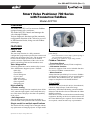
Smart Valve Positioner 700 Series
with FOUNDATION fieldbus
Model AVP703
OVERVIEW
The model AVP703 is a FOUNDATION fieldbus
equipped smart valve positioner.
The model AVP703 controls and manages the
valve through Fieldbus.
Various diagnostic functions and the automatic
configuration function of the 700 series, as well
as PID function blocks, bring out real fieldbus
advantages.
FEATURES
Easy to use
• Auto- setup
The auto-setup function is a fully-automatic
configuration program that specifies the actuator and
adjusts zero and span of the valve. The program can
be run with the simple operation of an external
switch so that the adjustments of the valve can be
quickly and safely performed in hazardous areas.
can be modified to suit any application without any
parts change.
• Flow characteristic: Linear, EQ%, Quick opening or
user customized characteristics
• Actuator type: Double or single acting actuator
Fieldbus Functions
• Transducer Block
Positioner Transducer Block (FF-906 compliant)
• Link master function
This device supports Link Active Schedule function
for control of fieldbus communication.
• Alarm function
Alarm functions specified by FOUNDATION fieldbus
specifications are supported, such as various high or
low alarms, block alarm notices, etc. Alarms are
output in compliance with NAMUR NE107.
Valve diagnostics
Following parameters can be monitored by Control
Valve Maintenance Support System “Valstaff”.
• Stick Slip
• Total Stroke
• Travel Histogram
• Cycle Count
• Shut-Off Count
• Max. Travel Speed
• Valve signature
• Full stroke test
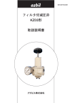
China RoHS
High reliability
This device is used in the Oil & Gas, Petrochemical,
Chemical, Pulp & Paper, Food & Beverage,
Machinery, Steel/Metal & Mining, and Automobile
industries and therefore does not fall under the China
RoHS Legislation.
If this device is used in semiconductor manufacturing
equipment, labeling on the device and documents for
the China RoHS may be required. If such documents
are required, consult an azbil corp. representative.
• Positive seating
The positive seating function completely shut off the
valve when the input signal is lower than that set by
user. This allows full play to the shut-off capability
of the valves.
• Self-diagnostics
The self-diagnostic function provides the ability to
check the status of the positioner and to alert the failure.
Single model for multiple specifications
The model AVP703 settings can be changed without
any replacement of changing of parts. A single model
Specifications are subject to change without notice.
-1-
No. SS2-AVP703-0100
Azbil Corporation
FUNCTIONAL SPECIFICATIONS
PHYSICAL SPECIFICATIONS
Applicable actuator
Enclosure rating
• Single and double acting actuator
• Linear and rotary motion actuator
JISC0920 watertight, IP66
Approvals
Baked acrylic
Finish
ATEX Flameproof and Dust approval
Color
II 2 G Ex d IIC T6 Gb at -30°Ct ≤ Tamb ≤ +75°C
II 2 D Ex tb IIIC T 85°C Dd -30°C ≤ Tamb ≤ +75°C
IEC IP66
Silver
IECEx Flameproof and Dust approval
Weight
Ex d IIC T6 Gb -30°C ≤ Tamb ≤ +75°C IP66
Ex tb IIIC T85°C Db -30°C ≤ Tamb ≤ +75°C IP66
Without Pressure regulator with filter : 4.2 kg
With Pressure regulator with filter
: 4.9 kg
Material
Cast aluminum
Output characteristics
INSTALLATION
• Linear, Equal percentage, Quick opening
• Custom configurable 21 segments
Air connections
Stem travel range
Rc1/4 or 1/4NPT internal thread
Feedback Lever Angle ±4° to ±20°
Electrical connections
Bypass operation
G1/2, 1/2NPT or M20 × 1.5
Auto/Manual external Switch (For single acting type only)
Air supply pressure
Particles
140 to 700 kPa {1.4 to 7.0 kgf/cm2}
Maximum diameter 3 µm
Air consumption
Oil mist
at the stable output 50%
3.2 /min (N) maximum at 140 kPa {1.4 kgf/cm2}
4.0 /min (N) maximum at 280 kPa {2.8 kgf/cm2}
4.8 /min (N) maximum at 500 kPa {5.0 kgf/ cm2}
8 /min (N) maximum at 400kPa {4.0kgf/cm2}
for double acting type
Less than 1 ppm at mass
Humidity of the air supply
The dew point should be at least 10°C lower than the
temperature of this device.
Maximum air deliver flowrate
110 /min (N) at 140 kPa {1.4 kgf/cm2}
Lightning protection
Peak value of voltage surge: 12 kV
Peak value of current surge: 1000 A
Vibration tolerance
2 G (5 to 400 Hz)
(with standard mounting kit on Azbil Corporation HA
actuator)
Ambient temperature limits
Waterproof:
ATEX Flameproof:
IECE Flameproof:
Conditions of supply air (JIS C1805-1 (2001))
-40°C to +80°C (LCD: 0 to +50°C)
-30°C to +75°C
-30°C to +75°C
CE conformity
Electromagnetic compatibility
EN61326-1: 2013 (CE marking)
Ambient humidity limits
5% to 100% RH
PERFORMANCE SPECIFICATIONS
Accuracy
±1% F.S. (±2.5% with custom output characteristics)
-2-
Azbil Corporation
No. SS2-AVP703-0100
FIELDBUS SPECIFICATIONS
Function Blocks
Block
name
Number
Period of
execution
(ms)
AO
1
30
Note
For Set Point
DI
2
30
For limit switches
AR
1
30
Arithmetic block perform an arithmetical operation to the process measurement
value.
PID
2
45
PID function block execute a control algorithm to minimize the error as the difference between a measured process variable and desired set-point. It also has functions of cascade control, feed forward control, and alarm detection.
OS
1
30
Output splitter block perform the sprit control operation.
IS
1
30
Input selector block perform the control of select the process value.
VCR Structure
The AVP has 32 VCRs (Virtual Communication Relationships), of which the first one is dedicated to the SMIB/NMIB
defined by the Foundation Fieldbus specifications. The rest of the VCRs are fully configurable.
VCR No.
Configuration
1
2-32
QUB (Server) for NMIB/SNIB
Fully configurable
Network Parameters
The following table shows the key parameter values that affect interoperability of the Fieldbus devices. The LAS needs to
be configured to satisfy these parameters. If other devices on the same Fieldbus network require a greater number for
them, the greater number must be used. This will degrade network performance, though.
Symbol
Parameter
Factory Setting
Range of Value
V (ST)
Slot Time *1
5
5 to 100
V (MID)
Minimum Inter PDU Delay *1
10
10 to (V(MRD)-1)×V(ST), smaller than 120
inclusive.
V (MRD)
Maximum Response Delay *2
4
V(MRD)×V(ST) shall be greater than
20 and V(MRD) shall be smaller than
11, inclusive.
T1
SM Step Timer
48000
(15 seconds)
T2
SM Set Address Sequence Timer
2880000 (90
seconds)
T2 > T3
T3
SM Set Address Wait Timer
1440000 (45
seconds)
T2 > T3
V (FUN)
First Unpolled Node
0x25
0x14 to 0xF7
---
V (NUN)
Number of consecutive Unpolled-Node
0xBA
0x00 to oxE4
V(MSO)
Maximum Scheduling Overhead *1
0x00
0x00 to 0x 3F
V(DMDT) Default Minimum Token Delegation time 0x56
*1
0x20 to 0x7FFF
V(DTHT) Default Token Holding Time *1
0x0400
0x0114 to 0xFDE8 (65,000)
V(TTRT)
Target Token Rotation Time *1
4096
1 to 60000ms
V(LTHT)
Link Maintenance Token Holding Time
*1
0x0124
0x0124 to 0xFDE8 (65,000)
V(TDP)
Time Distribution Period
5000
5 to 55000ms
V(MICD)
Maximum Inactivity to Claim LAS Delay 2000
*1
1 to 4095
V(LDDP)
LAS Database Distribution Period
100 to 55000ms
3000
-3-
No. SS2-AVP703-0100
Note)
Azbil Corporation
• A LAS requires parameters other than those listed here to operate. Please refer to the user's manual that comes with your LAS
device.
• The T3 needs to be set between 15 seconds and 60 seconds.
*1. The unit is octet time (256 μs).
Octet time is the time required to handle 8 bits of data on the Fieldbus Network.
*2. The unit is slot-time.
Supply voltage
9 to 32 V
Maximum Current 20 mA
Registration
Interoperability test ITK 6.1 approved.
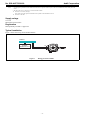
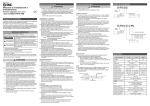
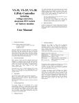
Typical installation
Figure 1 shows the wiring for the model AVP703.
Fieldbus
Another
fieldbus device
FB
FB
Figure 1
Wiring for model AVP703
-4-
Azbil Corporation
No. SS2-AVP703-0100
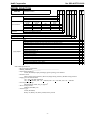
MODEL SELECTION
AVP703
(1) Structure
(2) Connection
(3) Finish
-
F OUNDATION Fieldbus
(1) (2) (3) - (4) (5) (6) (7)
Water-proof
X
ATEX Flameproof (Electrical connection G1/2 is not available) C
IECEx Flameproof (Electrical connection G1/2 is not available) D
Pressure gauge
Electrical
Air piping
Mounting thread
thread
connection
connection
Rc1/8
G1/2
Rc1/4
M8
Rc1/8
1/2NPT
1/4NPT
M8
Rc1/8
1/2NPT
1/4NPT
5/16-8UNC
Rc1/8
M20 x 1.5
1/4NPT
M8
Standard (Baked acrylic)
Corrosion proof (Baked urethane)
-
(8) (9)
G
N
U
M
S
B
(4) (5) Display
(6) (7) Diagnostic
D
Display with push button
Advanced Diag (with four pressure sensors)
X
A
X
-
(8)(9) Option
None
Model KZ03 pressure regulator with filter (Mounted on Positioner)
Model KZ03 pressure regulator with filter (with bracket for separated mount)
Extention lever (In case of no mounting bracket)
Seal tape prohibited
Mounting bracket material SUS316 (In case of with mounting bracket)
Mounting bracket (PSA1, 2)
Mounting bracket (PSA3, 4)
Mounting bracket (PSA6, VA4 to 6)
Mounting bracket (PSA7)
Mounting bracket (HA1)
Mounting bracket (HA2, HL2)
Mounting bracket (HA3, HL3)
Mounting bracket (HA4, HL4)
Mounting bracket (DAP560, 1000, 1000X)
Mounting bracket (DAP1500, 1500X)
Individual specifications
• PD_TAG (max 32 character):____________________________
• NODE_ADRESS:0x___________
• Input Characterization:
Linear (Standard), Equal persentage, Quick opening, User-defined
• Psitioner action:
Direct (Single acting actuator), Reverse (Single acting actuator), Double acting actuator
• Supply pressure classification:
150 < PS < 300 kPa (Standard)
140 < Ps < 150 kPa, 300 < Ps < 400 kPa, 400 < Ps < 450 kPa, 450 < Ps < 700 kPa
• Unit of pressure gauge:
kPa (Standard) , MPa, bar, psi, kgf/cm2
• Valve closed position:
DOWN (Standard), UP
• Actuator type:
Linear (Standard)
Rotary 90, Rotary 60, Rotary sub90, Rotary sub 60
-5-
X
M
M
M
M
M
Y
Y
Y
Y
Y
Y
Y
Y
Y
Y
X
1
2
L
J
6
S
Q
L
8
A
T
C
N
4
5
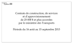
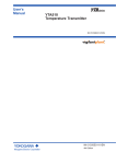
DIMENSIONS
Shows the typical dimensions of AVP703.
[Unit: mm]
Output 1 air connection
142.4
OUT1
72.8
201.5
148.7
86.5
74.5
65
64
64.5
64.5
Air supply connection
70
55.5
Output 2 air connection
Conduit
OUT2
SUP
Figure 2 Dimensions of AVP703
Note
• HART is registered trademark of HART Foundation.
• FOUNDATION is a trademark of Fieldbus Foundation.
1st edition: Feb. 2014