1
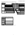
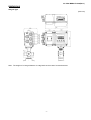
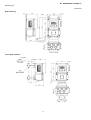
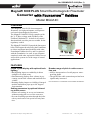
No. SS2-MGG21F-0100 (Rev.1) MagneW 3000 PLUS Smart Electromagnetic Flowmeter Converter with FOUNDATION™ fieldbus Model MGG14C OVERVIEW The MagneW 3000 PLUS electromagnetic flowmeter is a high performance, microprocessor-based electromagnetic flowmeter. The MagneW 3000 PLUS fully complies with the 31.25 kbps voltage mode Fieldbus of the Fieldbus Foundation™. Its built in AI control function block provides process variable for the regulatory control. The MagneW 3000 PLUS passed the Interoperability Test Program developed by the Foundation to assure maximum interoperability with other Foundation Fieldbus devices, and is registered with the Foundation. As such, it can cooperate seamlessly with other registered field devices as well as host systems in a wide range of control applications. (Remote converter) FEATURES Liquid crystal display with optional backlighting • Backlighting improves readability in direct sunlight or in a dark room. • Simultaneously displays flow volume in percentage, actual flow volume and totalized flow volume. • Rotating display improves visibility of integral models mounted on pipes up to 90° degrees from standard. Broader range-of-pitch in cable connection port • Allows incorporation of an all-purpose waterproofing gland. • The pitch of the cable connection port has been significantly increased. FOUNDTION™ is a trademark of the Fieldbus Foundation. Setting parameters by optional infrared ray touch sensor • Allows safe-setting, in severe environments, without opening the cover of the converter. • Prevent unwilling operation through the infrared ray touch sensor via special security function. Specifications are subject to change without notice. -1- First issue: Dec. 1999 Rev.1: Aug. 2000 No. SS2-MGG21F-0100(Rev.1) APPLICATIONS FUNCTIONAL SPECIFICATIONS Pulp and Paper Pulp liquids, chemicals, corrosive liquids, industrialwater, wastewater, etc. Type of protection JIS C 0920 Waterproof model NEMA ICS6-110 TYPE4X IEC PUBL 529 IP66 Petroleum/petrochemical/chemicals Corrosive liquids, dyestuffs, chemicals, industrial water, waste water, etc. Public utilities Water supply systems, sewage systems, community drainage, human waste, sludge, sediment slurry, regulation of total effluent, etc. Measurable electrical conductivity (with detector of 2.5mm to 1100mm in diameter) 3µS/cm or more (consult your Yamatake engineer when conditions are 3µS/cm or less.) Input signal Flow signal Electromotive force from the detector Food Potable water, light, medium and high density fluids, industrial water, waste water, etc. Output signal Steel/nonferrous metals/ceramics Alumina slurry, cooling water, industrial water, corrosive liquids, wastewater, etc. Unit of flow indication Machinery/equipment/electric machinery Corrosive liquids, cooking water, circulating water, industrial water, waste water, etc. Construction Building material slurry, sediment slurry, cement slurry, industrial water, etc. Flow output Fieidbus output Can be selected from between percentage, volume flow, mass flow, time. 3 3 Indication of volume flow : m , L, cm , G, mG, kG, B Indication of mass flow : t, kg, g, lb Indication of time : d, h, min, s Lightning protection 12kV, 1000A Equipped with the lighting arrester in the power source and external input and output terminals. Power failure Shipbuilding Sediment slurry, etc. Electric power Corrosive liquids, cooling water, industrial water, wastewater, etc. Gas Circulating water for air conditioning, etc. An EEPROM retains data record of totalized flow volume when pulse output is used (retention period approximately 10 years). Power supply AC100V, 110V, 115/120V±10% AC200V, 220V, 230/240V±10% Frequency 50Hz or 60Hz, DC24V±10% Power consumption Within 13W (17VA) Ambient temperature limits -25 to +60°C Ambient humidity limits 5 to 100% RH -2- No. SS2-MGG21F-0100(Rev.1) PERFORMANCE SPECIFICATIONS Optional specifications Accuracy Display Indication by LCD with backlighting in combination with a detector Main display <diameter 2.5 to 15mm>Upper limit value of Vs=set velocity range 7-segment, 6 digits Sub display Vs(m/s) 16 digits, 2 lines 1.0≤Vs≤10 Display contents 0.1≤Vs≤1.0 Demonstrates three values simultaneously Velocity during measurement≥Vs×40% ±0.5% of indicated value ±(0.1/Vs+0.4)% of the indicated value Velocity during measurement≤Vs×40% ±0.2% of Vs ±0.4(0.1/Vs+0.4)% of Vs <diameter 25 to 600mm> Upper limit value of Vs=set velocity range • Flow volume in percentage Vs(m/s) • Actual flow volume 1.0≤Vs≤10 • Totalized flow volume (when pulse output selected) 0.1≤Vs≤1.0 Selection of main display and secondary display Velocity during measurement≥Vs×20% ±0.5% of indicated value ±(0.1/Vs+0.4)% of the indicated value Velocity during measurement≤Vs×20% ±0.1% of Vs ±0.2(0.1/Vs+0.4)% of Vs <diameter 700 to 1100mm>Upper limit value of Vs=set velocity range Velocity during Velocity during Vs(m/s) measurement≥Vs×50% measurement≤Vs×50% 1.0≤Vs≤10 ±1.0% of indicated value ±0.5% of Vs ±(0.2/Vs+0.8)% (0.1/Vs+0.4)% of Vs 0.1≤Vs≤1.0 of the indicated value Main display is selectable from three values. Data setter Setting by infrared ray touch sensor Infrared ray touch sensor: four key switches PHYSICAL SPECIFICATION Functions of built-in counter Finish Totalizer According to pulse scale setting, it totals one count at a Standard Acrylic resin time, for normal and reverse flows. Corrosion - resistant Acrylic resin Corrosion - proof Epoxy resin Empty-status detection When the detector is empty, the output is fixed at zero. Color Display is latched to zero. Light beige (Munsell 4Y7.2/1.3) Certification of traceability Main body material The following three documents are provided. Aluminum alloy Tropicalization treatment (for transportation/ storage) Protects the electromagnetic flow meter in harsh environ- Display cover material ments during transportation and/or storage. Tempered glass, 5mm thick Aluminum alloy The following treatments can be applied corrosion protection, moisture prevention and mildew proofing. Weight 3.7kg Indication other than SI units Units to be exported other than SI units. Those units are as follows INSTALLATION Volume unit Electrical Connection B (barrel), kG (kilo-gallon), G (gallon), G1/2 (PF1/2) internal threads CM20 internal threads, Pg 13.5 mG (milli-gallon) internal threads Mass unit Mounting lb Integral detector/converter Tag number on terminal box Wall mounting, 2inch pipe mounting The designated tag numbers (maximum 16 characters) Grounding should be stamped on a plate, which is attached to the terminal box. One line can contain 8 characters, so if more Resistance lower than 100 Ω characters must be written on two lines. Characters can be upper-case English letters, numbers and hyphens (-). PT1/4 air purge hole One of the cable connection ports is a dedicated air purge hole with threads for a PT1/4 screw. For additional specifications, please contact your Yamatake representative. -3- No. SS2-MGG21F-0100(Rev.1) FIELDBUS SPECIFICATIONS Blocks supported by the MagneW 3000 Name of Block Num ber Explanation Resource Block 1 The Resource Block(RB) maintains overall resources of the MagneW 3000. Transducer Block 1 The Transducer Block(XB) interfaces with the sensing element of the MagneW 3000, converts the measured value in engineering units specified, and sends it to the Al Function Block. Al Function Block 1 The Al Function Block(Al FB) accepts an analog input signal from the XB, scales it, detects alarm conditions, and provides it in a uniform format in the Fieldbus network. VCR Structure The MagneW 3000 has 16 VCRs (Virtual Communication Relationships), of which the first one is dedicated to the SMIB/NMIB defined by the Foundation Fieldbus specifications. The rest of the VCRs are fully configurable. Their default configurations are shown below: VCR Configuration No. 1 VCR Configuration No. QUB(Server) for 9 QUU(Source) QUU(Source) NIMIB/SNIB 2 BNU(Subscriber) 10 3 BNU(Subscriber) 11 QUU(Source) 4 BNU(Subscriber) 12 QUB(Server) 5 BNU(Subscriber) 13 QUB(Server) 6 BNU(Subscriber) 14 QUB(Server) 7 BNU(Subscriber) 15 QUB(Server) 8 QUU(Source) 16 QUB(Server) Network Parameters The following table show the key parameter values that affect interoperability of the Fieldbus devices. The LAS need be configured to satisfy these parameters. If other devices on the same Fiedlbus network require a greater number for them, the greater number must be used. This will degrade network performance, though. Symbol Parameter name Range of Values V(ST) Slot Time 4 to 100 V(MID) Minimum Interframe Gap 10 to (V (MRD) -1) x V (ST), smaller than 120 inclusive. V(MRD) Maximum Response Delay V (MRD) x (V (ST) shall be greater than 20 and V (MRD) shall be smaller than 11, inclusive. T1 SM Step Tuner 96000(3 seconds) T2 SM Set Address Sequence Timer 1920000(60 seconds) T3 SM Set Address Wait Timer 480000(15 seconds) Note: An LAS requires parameters other than those listed here to operate. Please refer to the user’s manual that comes with your LAS device. Note: The T3 need be set between 15 seconds and 60 seconds. -4- No. SS2-MGG21F-0100(Rev.1) MODEL SELECTION MagneW 3000 PLUS (Fieldbus model) (Converter/Integral Type) Basic Model No. Selections Optional selections MGG14C Power supply AC100V 50/60Hz AC110V 50/60Hz AC115/120V 50/60Hz AC200V 50/60Hz AC220V 50/60Hz A B C D A C E H E J AC230/240V 50/60Hz DC24V AC Noise filter 50Hz DC24V AC Noise filter 60Hz Fieldbus F G H Output signal/ Communication Electrical connection/ G1/2 internal thread/Without watertight gland Watertight gland G1/2 internal thread/With brass(Ni-plated) watertight gland G1/2 internal thread/With plastic watertight gland 1/2NPT internal thread/Without watertight gland CM20 internal thread/Without watertight gland Pg13.5 internal thread/Without watertight gland Others Installation/ Wiring direction Options - Integral model Y Empty-pipe detection Certification of traceability Tropicalization treatment Indication other than SI units Attachment of the TAG number to the terminal box Yamatake Version (must be selected) Others U F 1 2 3 4 5 6 U Horizontal piping mounting/Upstream side A Horizontal piping mounting/Downstream side X Finish Standard finish 1 Corrosion-resistant finish 2 Corrosion-proof finish 0 None X Display with data setting device With display and data setting device A B Horizontal piping mounting/Left side viewed from upstream Horizontal piping mounting/Right side viewed from upstream Vertical piping mounting/Downstream side (Flow direction :Downstream to upstream) Others C X Contact inputs/output None D E U - 5- X Approval None No. SS2-MGG21F-0100(Rev.1) MagneW 3000 PLUS (General) (Converter/Remote Type) Basic Model No. Selections Optional selections MGG14C Power supply AC100V 50/60Hz AC110V 50/60Hz AC115/120V 50/60Hz AC200V 50/60Hz AC220V 50/60Hz AC230/240V 50/60Hz DC24V AC Noise filter 50Hz DC24V AC Noise filter 60Hz Fieldbus A B C D E F G H Output signal/ F Communication Electrical connection/ G1/2 internal thread/Without watertight gland Watertight gland G1/2 internal thread/With brass(Ni-plated) watertight gland G1/2 internal thread/With plastic watertight gland 1/2NPT internal thread/Without watertight gland CM20 internal thread/Without watertight gland Pg13.5 internal thread/Without watertight gland Others Installation/ Remote model Wiring direction Options A B C E H Empty-pipe detection Pulse output(Open collector) Certification of traceability Tropicalization treatment Indication other than SI units Attachment of the TAG number to J the terminal box Yamatake Version Y (must be selected) 1 2 3 4 5 6 X Finish 1 2 G 2 in. pipe mounting/With standard bracket Standard finish Corrosion-resistant finish Corrosion-proof finish Display with data setting None device With display and data setting A device X Wall mounting/With standard bracket H Others X Contact inputs/output X Approval Converter Terminal Correspondence Table Symbol Description A B Flow rate signal input C SA SB FIELDBUS + - Fieldbus output Excitation output X Y POWER AC L Power supply N E Others Not used Grounding resistance lower than 100Ω Note) When the power supply is 24 VDC, ″POWER AC″ should read ″POWER 24 V DC″ - 6- None None No. SS2-MGG21F-0100(Rev.1) DIMENSIONS Integral Type (Unit:mm) Note: The weight of an integral detector is 100g less than the mass of remote detectors. -7- No. SS2-MGG21F-0100(Rev.1) Remote type (Unit:mm) Wall mounting 2-inch pipe mounted -8- No. SS2-MGG21F-0100(Rev.1) Integral Type (Unit:mm) Note: The weight of an integral detector is 100g less than the mass of remote detectors. -9- Note Note Advanced Automation Company 1-12-2 Kawana, Fujisawa Kanagawa 251-8522 Japan URL:http://www.azbil.com Printed on recycled paper.