1
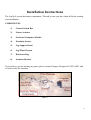
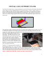
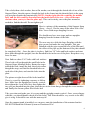
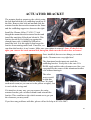
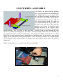
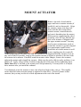
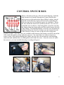
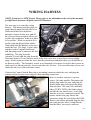
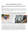
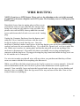
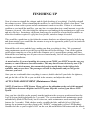
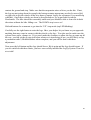
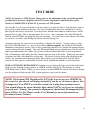
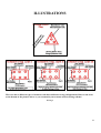
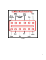
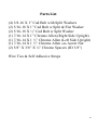
Installation Manual
Harley Touring Bikes
2009 - UP
Version 3
Copyright 2011, Pete Giarrusso, Inc.
D/B/A Chopper Design Services
All Rights Reserved
2
Table of Contents
INTRODUCTION .................................................................................... 4
WARRANTY ............................................................................................ 5
INSTALLATION INSTRUCTIONS ...................................................... 6
COMPONENTS: .................................................................................................... 6
1)
2)
3)
4)
5)
6)
7)
8)
Control Switch Box...................................................................................................... 6
Linear Actuator ........................................................................................................... 6
On-board Computer Module ....................................................................................... 6
Proximity Sensor ......................................................................................................... 6
Leg Support Stand ....................................................................................................... 6
Leg/Wheel System ........................................................................................................ 6
Hardware Bag.............................................................................................................. 6
Actuator Bracket.......................................................................................................... 6
PREPARE FOR INSTALLATION ...................................................................... 7
INSTALL LEG SUPPORT STAND ........................................................................ 8
ACTUATOR BRACKET .................................................................................... 10
LEG/WHEEL ASSEMBLY ................................................................................ 11
MOUNT ACTUATOR ......................................................................................... 12
CONTROL SWITCH BOX ................................................................................. 13
WIRING HARNESS ............................................................................................ 14
INITIAL SYSTEM TEST .................................................................................... 16
MOUNT PROXIMITY SWITCH ....................................................................... 17
WIRE ROUTING ................................................................................................. 18
FINISHING UP ..................................................................................................... 19
ACTUATOR ADJUSTMENT (Maintenance Mode) ....................................................... 19
TEST RIDE ........................................................................................................... 21
LEGUP LITE - ADDENDUM ............................................................................. 23
ILLUSTRATIONS ............................................................................................... 24
Wiring 1 ............................................................................................................................ 24
Wiring 2 ............................................................................................................................ 24
Wiring 3 ............................................................................................................................ 25
PARTS LIST.............................................................................................................. 26
3
Introduction
This manual covers installation of the LegUp Landingear system by Chopper Design Services.
This system should only be installed by a qualified technician, or those with above average
mechanical skills. If you are not SURE that you can perform this installation, please contact us
and we will help you find a qualified shop to assist you.
If you have been looking for a system that will keep your feet on the pegs, this is NOT the
system for you! On the other hand, if a system that will relieve you of the weight of the bike
and help you avoid balance problems as you approach a stop, LegUp is what you need.
Improper installation will void your warranty, so please be very careful!
Thanks for choosing LegUp!
4
Warranty
Chopper Design Services warrants the LegUp system for a period of one year from date of
purchase. This warranty covers replacement parts and/or manufacturer defects. Incidental
damages or costs are the responsibility of the purchaser.
Defective parts are to be returned to Chopper Design at the address below. Purchaser must
contact Chopper Design to receive a Return Material Authorization, prior to returning defective
parts to Chopper Design.
Abuse, improper installation or use, collisions or accidents, are not covered under this warranty.
Replacement parts for this type of damage are available through Chopper Design.
Users of the LegUp system agree that Chopper Design is NOT responsible for personal injuries
or damage to property arising from the use of the system. While we believe this system to be
safe and reliable, the user is advised that use of LegUp is done so at the users’ own risk. Use of
the system implies agreement to the above statements. If you can’t agree with the above,
Chopper Design and its dealers would be happy to refund your full purchase price, before you
use the LegUp System.
Chopper Design Services
1365 Bennett Dr #101
Longwood, FL 32750
407-834-5007
[email protected]
5
Installation Instructions
The LegUp® system has many components. Pleased be sure you have them all before starting
your installation.
COMPONENTS:
1)
Control Switch Box
2)
Linear Actuator
3)
On-board Computer Module
4)
Proximity Sensor
5)
Leg Support Stand
6)
Leg/Wheel System
7)
Hardware Bag
8)
Actuator Bracket
If you believe you are missing any parts, please contact Chopper Design at 407-834-5007, and
we will rectify the situation.
Figure 1
6
PREPARE FOR INSTALLATION
NOTES on 2009 AND LATER BIKES:
2009 and later Harley-Davidson touring bikes MUST use a 2 into 1 Exhaust on
the right side of the bike! We recommend the Freedom Performance Union
exhaust (website below). While other exhausts may work, we can’t know if you
will get the full height of the wheels or the clearance required with any other
exhaust system.
(http://freedomperform.com/shop/?page_id=3&category=3&product_id=170)
Place the motorcycle on an acceptable bike lift. You will need to keep the bike on its wheels
for most of the installation, and jack the rear wheel off the lift for some portion of the
installation. Make SURE the motorcycle is secure on the lift!
Remove the seat, saddlebags and side covers, they are not needed until the very end of the
installation.
We are now ready to begin!
7
INSTALL LEG SUPPORT STAND
LegUp has developed a new, stronger attachment system which replaces the Harley-Davidson®
center stand previously included in the kit! If you already have a 2 into 1 exhaust, remove or
loosen it, otherwise take off your existing exhaust as you will need to install such an exhaust.
Remove the right front floorboard and the left rear floorboard. These need to be removed to
allow access to the swing arm pillow block lower bolts, which attach the support stand to the
motorcycle.
Leg Support Stand
We install this stand by attaching front and rear supports then sliding the plate in place. We start
by finding the uprights (left and right, ninety degree brackets with plates attached). The taller
upright goes on the right side of the bike (the far side in this picture). Remove the bottom bolts
from the swing arm pillow blocks and set
them aside. The right one may have a cap
rather than a bolt. These bolts are the ones
under the big chrome circles where the swing
arm meets the frame. Install a supplied
chrome bolt in each Upright (left one shown
here) and leave the upright hanging. Do not
tighten yet!! Do the same on the other side of
the bike. Use some Loctite on these and all the
bolts you install on the bike!
Find the 3/8” Strap (green above) and the (2)
Front Support Straps (3/16” steel, 4.25” long,
with a small hole and a slot in them), (2) 5/16” bolts and lock washers, and 2 Chrome spacers.
Place the strap above the cross-brace that is under the transmission; it should fit right in and
slide a bit back and forth once placed. (NOTE: The three holes on the strap should be on the
right, or throttle side of the bike, with the two holes, toward the left!)
8
Take a bolt, then a lock washer, then a flat washer, run it through the slotted side of one of the
Support Plates, then the spacer, though the hole in the frame into the threaded hole in the strap
you just placed under the transmission (NOTE: On the right side this would be the middle
hole, and the left would be threaded into the inside hole of the two… this will become
obvious when you try to line the plate up!). This can be tricky; move the plate around as
needed to find the threads! Do not tighten yet!
Here is a picture of the mounting of this Support Strap
(fuzzy…sorry!). Do the same on the other side of the
bike. Leave both straps dangling for now.
We should now have two straps and two uprights
hanging from the bottom of the bike.
The next step is to slide the large flat plate with the
pipe on one end under the rear uprights. This gets
installed with the pipe toward the rear of the bike and
the offset of the pipe up (the bottom of the plate should
be completely flat). Once the plate is in place, find four 3/8” bolts and lock washers and start
these bolts through the uprights, into the threaded holes in the rear of the plate. Keep these very
loose for now.
Next find two short 5/16” bolts with lock washers.
These bolts will go through the small hole in the
Support Straps installed earlier. Rotate the straps
toward the back, install the bolt, then lock washer
though the strap, and find the threaded holes on
each side of the plate, and start the bolts into the
plate.
The picture at right shows all the bolts installed.
There is a specific tightening sequence to follow
here. Make sure the uprights are exactly vertical,
then tighten the 4 rear bolts first, then tighten the
two you just threaded into the plate, then the two in the front that go through the cross-member
and finally the chrome pillow block bolts last!
Take your time and make sure it is secure and the uprights remain vertical. Once you are happy
with this, you should double check all of the bolts! This Plate should be very secure to the bike;
give it a tug. It should be one with the motorcycle!
Once the support stand is installed, we can move onto the installation of the actuator bracket.
DO NOT Reinstall the Exhaust System or Floorboard Yet!
9
ACTUATOR BRACKET
The actuator bracket mounts to the vehicle using
the bolt that holds the left saddlebag/crash bar to
the bike. Remove this bolt and nut and slide the
actuator bracket between the mount on the frame
and the saddlebag support as shown to the right.
Install the Chrome Allen (7/16X1.5”) bolt
though the mount then the actuator bracket and
install the matching Nylock nut behind it. This
bracket should fit very tightly up against the
slanted frame rails; it should be difficult to
install the bolt. It is this tight fit that keeps this
bracket from rotating under load. If need be, we
can shim this bracket; it can’t rotate. Make sure you tighten it securely! Note: IF the fit is too
tight, you can use the stock nut and bolt, but again, make sure the bracket does not rotate!
Once installed, there are two things you need to
check. Clearances are very tight here!
The aluminum bracket must not touch the
saddlebag bracket. Verify this is the case. If it
DOES touch and the other clearances are fine, you
can grind/file the corner of this aluminum bracket
a bit without hurting it.
The other
worry would
be that this
same bracket has clearance from the swing-arm. We don’t
need much room (as you can see in the picture at right!), but
it can’t rub the swing-arm!
If it interferes in any way, you can remove the entire
actuator bracket, put a washer behind it and reinstall the
bracket. This would move the whole mount out to get you
the clearance you may need!
If you have any problems with this, please call us for help at 407-834-5007!
10
LEG/WHEEL ASSEMBLY
First remove the bolts from the stainless
steel rod in preparation for mounting the
legs. With help from an assistant, slide
the Leg/Wheel Assembly around the rear
tire (careful of the finish!), and align the
Leg Mounting Points (green) with the
slots in the Support Stand. If available a
very small amount of ‘Never Seize’ on
the shaft is in order here. Then start the
stainless steel shaft in from one side
through the tube on the support stand,
and through the first leg mounting point
and its bushing. The fit is tight, so take your time. Carefully work the shaft through the tube
and the second leg mounting point. The shaft is inserted properly when there it is inserted just
past (approximately 1/8”) the end of the tube. This distance should be about the same on both
sides, but it is not critical as long as both sides are inside the tube. If you need to, you can tap
lightly on the shaft (brass drift is preferred here). Once the shaft is in place, use a small amount
of blue thread locker and install the (2) chrome bolts and washers on the end of the shaft to
finish it off.
Make sure the legs move up and down without any binding!
11
MOUNT ACTUATOR
Remove the axles from both the
upper and lower actuator mounts (if
installed), and set them aside. Align
the actuator, motor side (big end)
down with the hole in the lower
actuator mount, reinstall the axle,
and start it threading into the mount.
With someone supporting the wheel
assembly, raise the legs until the top
hole in the actuator is aligned with
the upper actuator mount. You may
need to enter maintenance mode to
extend the actuator to get this aligned
(see maintenance mode below).
Install the axle in this mount as well
(some wiggling may be required!).
At this point you need to make sure that the mounts are in alignment and the actuator is not in
any sort of bind! If possible, snug up the actuator mounts in whatever position is the best with
the actuator in its mounts. If needed, mark the mounts with a Sharpie, remove the actuator,
tighten the mounts and reinstall the actuator. Make sure the axles slide in easily and there is no
bind at all. Apply a drop of Blue Locktite to the threads of the axles before tightening them.
Make Sure there is no bind or the actuator will fail prematurely! You may have to re-adjust
these mounts after you install the exhaust!
You ultimately want the actuator to move the wheels as high as they can go. This usually
means that the bottom actuator mount is adjusted for this affect. It doesn’t matter at this
moment, but you may need to do a final adjustment at the end of the install.
12
CONTROL SWITCH BOX
Remove the bolt on the top of the left switch housing. Find the
long chrome bolt, thread it through the Control Switch Box,
insert spacer on bolt and (with a drop of Blue Locktite), thread
bolt into switch housing. Square the box before tightening the
bolt (you may have to re-align the mirror for clearance). Route
the wire inside the clutch lever and down the bar. Use wire ties
to hold the wire to the bar. On Fairing bikes, route the wire into
the fairing along the clutch cable and fish out the bottom left side
of the fairing. On Windshield bikes, route the wire down the bar,
and thread it into the Nacelle, fishing it out the bottom left side
of the Nacelle (it may be easier to tape the silver plug ends
together for this). Once the wires are available at the bottom of the fairing or nacelle, thread the
wires under the tank to end up under the seat area. On some bikes it is easier to loosen or
remove some of the tank mounting bolts. Make sure the wires do not interfere with anything
under the tank, and that there is nothing that would chafe the wires. Once the wires are under
the seat area, you can assemble the plug according to Figure 6.
13
WIRING HARNESS
NOTE: If you have a LITE System, Please refer to the addendum at the end of this manual,
for differences between a Regular and LITE Harness!
The next step is to route the wiring
harness. The harness and the plugs are
routed mostly under the left side cover.
Different models have different
amounts of space in this area, and all
the wires are long enough to allow you
to place the connectors in the best place
for your bike. What you need to do is
get the eight pin plug and the double
white plug from the harness to the area
under the seat. The large 12 place plug
attaches to the Computer Enclosure,
and that plug needs to land near the left
saddlebag. The plug from the
Actuator (5-wire) and the plug from the
Proximity Sensor (3-wire) need to route in the side cover area to meet their corresponding
plugs. At this point just route the wires into the general area and plan where you would like to
tie them up safely. The Proximity sensor is not mounted yet because we need to have power to
make sure it is placed perfectly, so just route the wire for now. You can collect any excess wire
under the side cover when the time comes.
Connect the Control Switch Box plug to its mating connector under the seat, and plug the
actuator and proximity sensor plugs to their matching connectors.
Next we need to connect to a power
source. On some models, Disconnect the
fender plug under the seat, and plug the
double white plug in-between the plugs
from the bike. On some 2010 and later
bikes (FLHX, FLTR), the fender plug is
not like the one shown here, so we plug
into the accessory connector instead. The
picture on the next page shows this
connector, under the seat below the ECM.
Remove the rubber plug and plug the four
pin (with just two wires; orange/black)
into the bikes’ accessory connector.
14
Next plug the computer enclosure plug in its mating connector as well. Lay the enclosure on the
lift or support it somewhere… Don’t dangle it by its cord! Don’t worry, the plugs only work
one way… you can’t make a mistake here!
Don’t tie down the wires just yet but
if you have all the plugs connected,
we can do a quick test of the system.
There are 2 things we want to check
here. We want to make sure the
controls work, and we want to check
the light on the proximity sensor is
functioning.
Illustration: Accessory Connector under the Seat.
15
INITIAL SYSTEM TEST
NOTE: If you have a LITE System, Please refer to the addendum at the end of this manual,
for differences between a Regular and LITE system. Skip this section if you have a LITE
System.
Turn your bike to Accessory Mode. Counter clockwise on Road Kings and dash mounted
switches or all the way clockwise on Electra Glide bikes. Typically your speedometer or
tachometer will illuminate as well as your rear fender light. At this point, have a look at the
yellow proximity sensor. The RED LED (ON The Sensor) Should Not Be Lit. Take a metal
object (screwdriver, wrench, etc) and hold it on the flat face of the sensor (it has a circle
embossed in it). The LED should light up, and go out when you move the metal away. If not,
check all your connections.
Next, press the rightmost pushbutton and hold it for at least 3 seconds. One or both LEDs on the
switch panel should light up; we really don’t care which at this point. If this occurs, you are
doing well. If both LEDs are flashing (maintenance mode) you can skip the next step which is
to press both buttons until both LEDs flash.
Next press both buttons for just an instant! If everything is working, the bottom or yellow LED
on the switch box should flash, and the top LED should be out. The next step, and be careful
here, is to touch the left button for a split second. The legs should move down just a bit. Touch
the right button, and they should move up. With the bike on the lift, you have to be very
careful here!
If all of the above has occurred, raise the legs. Press and hold the right button until it stops, and
turn the ignition switch off!
The test is now complete. Let’s move on to mounting the Proximity Sensor.
16
MOUNT PROXIMITY SWITCH
NOTE: If you have a LITE System, Please refer to the addendum at the end of this manual,
for differences between a Regular and LITE system. Skip this section if you have a LITE
System.
This step is crucial!! Understand it before starting. The proximity sensor tells the system
how fast the bike is traveling. The proximity sensor mounts to the lower shock bolt on the right
side of the bike. You need to jack up the rear wheel so we can spin it to test the sensor and its
placement. Make sure the bike is in neutral.
With the bike on the lift, the rear wheel off the lift and the bike in Neutral, remove the bottom
bolt from the right shock at the rear of the bike. Insert the ‘U’ shaped bracket with the proximity
sensor attached, behind the shock and in front of the hole in the
swing-arm, so the bolt will pass though it when reinserted.
Reinsert the shock
bolt and tighten the
nut just a bit, so the
bracket can move
freely, but snug
enough so it stays
where you put it.
Find the angle for the bracket that will allow the
rotor bolts on the brake rotor to pass by the
proximity sensor in the middle of the square
portion of the sensor. When you think you have
it, turn the ignition to Accessory position, and roll the wheel to make the bolts pass by the
sensor. Each time one passes the sensor, the LED on the sensor should go bright then off.
If this is not happening, you may need to get the sensor a bit closer to the pulley bolts (5MM is
a very small distance!). If you have to move the sensor closer, you may have to shim the back
of the bracket or bend it just a tad. No matter what you need to do, you MUST make sure that
as the wheel turns, the light works as described above! Once you are certain, tighten the shock
bolt and test it again! Rotate the wheel past all 5 rotor bolts and make sure the light blinks and
goes out each time. If all is perfect, you are done! The automatic retraction of the legs as well as
their deployment RELIES on this sensor being placed perfectly! Now we can route the wire.
17
WIRE ROUTING
NOTE: If you have a LITE System, Please refer to the addendum at the end of this manual,
for differences between a Regular and LITE system. The Proximity sensor is NOT part of the
LITE system!
Detach the Sensor from its mating plug to allow you to
permanently route its wires. Run the wire on top of the
swing arm, using the self-adhesive clips provided. (See
picture wire route in RED), then up under the seat and
across and down to the left-side cover area to its’ mating
plug.
Unplug the Computer Enclosure from the harness, and
using the Velcro, attach the enclosure with the wires
facing the right (as viewed from the rear. Once the
enclosure is attached, make a small groove in the bag that the wire can fit into without being
crushed, and route the wire outside the bag. Use a small file, Dremel tool, or a bur to make this
slot. Make sure it reaches its, mating plug, and that the plug will not rub on anything if the
enclosure is disconnected. Also make sure that is reasonably easy to plug and unplug this
connector with the bag loose. We suggest leaving the plug connection inside the bag, but it can
be left outside as it is waterproof.
Use wire ties to make sure that all wires will stay where you put them and that they will not
come on contact with the belt or anything else that moves.
While you still have the bike raised, turn on the LegUp system (see owners manual). It should
start in maintenance mode, but if it doesn’t, please enter maintenance mode (again in the
manual). Now carefully, lower and raise the legs and make sure the wires are not binding and
that they clear everything! Raise the legs most of the way and turn off the bike. Now we are
ready to button everything up.
18
FINISHING UP
Now it is time to reinstall the exhaust, and do final checking of everything! Carefully reinstall
the exhaust system. When reinstalling the mufflers, be careful that the wheels clear them! You
may need to turn on the system and use maintenance mode to test this. If there is a clearance
problem as you install the mufflers, you may have to rotate them just a small amount, to get the
clearance you need. Also check that the clamps are not binding on the mechanism as you lower
and raise the legs. Sometimes a different clamp may be needed for a heat-shield or muffler to
allow the clearance required. LegUp has Low-profile, stainless clamps if needed.
This would be a good time to check that the actuator brackets are adjusted properly; both for up
and down motion (you would like the actuator to stop at its uppermost point if you can) and side
to side to avoid binding.
Reinstall the side cover and the bags; making sure that everything is clear. We recommend
using maintenance mode to get the legs up high but still below the bags. Turn off the ignition
switch when complete so as not to have the computer set it’s up and down settings until later.
Reinstall the seat making sure all your wires are routed neatly, tied off nicely and don’t interfere
with the seat installation.
As noted earlier, if you are installing the system on an FLHX, you MUST invert the rear peg
mounts, or remove them to clear the actuator. This may have become obvious by now. Flip
the pegs over in their mounts, then mount the brackets upside down in the highest hole
available, and you are done. The passenger will still be comfortable and you will get the
clearance you need.
Once you are comfortable that everything is correct, double-check all your bolts for tightness,
and get the bike off the lift so you can dial in the actuator, and adjust the wheels.
ACTUATOR ADJUSTMENT (Maintenance Mode)
NOTE: If you have a LITE System, Please refer to the addendum at the end of this manual,
for differences between a Regular and LITE system. Skip this section if you have a LITE
System.
Once you have the bike on the ground, turn the ignition to the accessory position and start the
LegUp System (hold right button for 3 seconds). The system should enter maintenance mode
automatically (Both LEDs Flash), but if it does not, enter maintenance mode manually (Both
buttons for 3 seconds). With a helper nearby, straddle the bike, and hold it level. Hit both
buttons for an instant to get the system in the “DOWN” setting mode (yellow LED flashing).
Straddle the bike so your weight is NOT on the seat, hit and hold the left button until the wheels
19
contact the ground and stop. Make sure that the suspension raises a bit as you do this. If not,
the legs are not going down far enough, the bottom actuator mount may need to be moved left
or right a bit to get the wheels all the way down (Contact LegUp for assistance if you need help
with this). Once these wheels are down as described above, try to put both feet on the
floorboards. The bike should be reasonably stable and you should be able to lean a bit in both
directions without the bike falling over. The DOWN stop is now set!
Hit both buttons for a moment to get into the “UP” stop mode (top LED blinking).
Carefully use the right button to raise the legs. Have your helper let you know as you approach
anything that may come in contact with the wheels or the legs. You also need to make sure the
system clears pipes, clamps etc. If you can’t make the clearance to allow the legs to come up all
the way, you can set the up stop just below whatever is interfering (if not, you will likely set up
a permanent rattle!) Hit both buttons when complete, and you will be done with these
adjustment.
Now press the left button and the legs should lower. Hit it again and the legs should retract. If
you are satisfied with these limits, you have successfully installed the LegUp System. Time for
a test ride!
20
TEST RIDE
NOTE: If you have a LITE System, Please refer to the addendum at the end of this manual,
for differences between a Regular and LITE system. Deployment and Retraction of the
wheels is COMPLETELY MANUAL if you have a LITE System.
Get the bike to a clear paved mostly level area where you can test ride it. Start the bike, turn on
the LegUp system and lower the legs. The first test should be done in a straight line. Put the
bike in gear and slowly accelerate. You may notice that the bike tends to want to steer a small
amount left or right. This is normal unless it is severe. Once underway, the top LED should
flash at around 6 MPH, meaning the legs are retracting. You can lean on one wheel or the other
as you leave to reduce any darting the system may be giving you.
Assuming the legs are retracted, you should try to deploy the wheels. As you come to a stop,
the Green LED should be on. As you slow down (almost stopped), the Yellow LED should
illuminate at the proper speed. Once it does (sometimes hard to see), hit the left button and put
your feet down near the ground. The top LED should flash and you should soon feel the wheels
deploying underneath you! Make sure you are ready to balance the bike! Uneven ground or
lack of familiarity could make the bike want to lean one way or the other. With your feet ready
to balance the bike, this should be no big deal. The slower you are going when deploying the
wheels, the smoother the transition will be from wheels up to wheels down. Practice these
maneuvers until you are comfortable with the wheel adjustments and the system operation.
SEMI-AUTOMATIC DEPLOYMENT: Another way to deploy the legs is to hit the left button
while you are running at any speed over 10MPH with the wheels up. The bottom or yellow
LED should start to flash. When you slow down to around 8MPH the wheels will start to deploy
(see the red/green flash on top LED). Again prepare to put your feet down.
NOTE: The bottom LED Should not be LIT if the legs are up over 10MPH! In
the event it is, the wheels will deploy instantly if you try to set them as above; this
is dangerous! You MUST re-visit the sections on testing the proximity sensor.
You should always be aware that this light should NOT be on if you are traveling
at speed, and ‘Arming’ the system for deployment should only be attempted if the
lower LED is Not Lit! Please see the User Manual for more information on
Proximity Sensor Failure!
21
The next thing to try is to make a turn right after a dead stop with the wheels down. As soon as
you start the bike moving, try a left or right turn immediately by leaning into that turn. You
may find that you have to nudge the bike a little bit more than usual to get the bike to lean, and
you won’t be able to lean as far as you can with the wheels up. Once into the turn, accelerating
will raise the wheels. You will hardly notice the wheels coming up unless you see the top LED
blinking!
The next thing to try is slow speed maneuvering with the wheels lowered. In a straight line on
level ground, you should be able to keep your feet on the floorboards and move the bike
forward at very slow speeds (simulate stop and go traffic). I like keeping my feet near the
ground during these maneuvers! You can also try small ‘Trike’ turns; keeping the bike upright
at slow speed and making turns as you would in a parking lot. Be aware that if you get over the
speed that the legs come up, they will!!! Another thing I like to do is donuts. Start out slow,
lean the bike left or right, and make circles at very slow speeds (throttle on, rear brake on,
clutch slipping… you know like the cops do!). This helps you get familiar with the wheels
being on the springs and allowing a lean angle!
Practice, practice, practice!! Enjoy your LegUp System!
22
LEGUP LITE - ADDENDUM
If you have a Lite System, there are a few differences in the wiring compared to our Regular
system.
The plugs and their locations don’t change at all! Instead of plugging in the computer to the
twelve pin plug, the Relay-Pack gets plugged into this plug. The Relay-Pack will be attached
with Velcro as the computer would have been in the same location.
On the LITE system there is no proximity sensor, so ignore the testing and mounting of this
sensor, and realize that the three pin plug will be left without a mating connector. We keep this
plug in the wiring harness in case you upgrade to a regular system in the future.
Using Your Lite System:
Unlike our Regular System, you don’t turn the LITE system on, or adjust the legs as described
in the ‘Maintenance Mode’ section of the manual. When you turn your bike on, the LITE
system is ready to go! Press and hold the left button to lower the wheels, press and hold the
right button to raise them. No lights will flash; it is up to you to control the system manually!
Please use EXTREME Caution when using the LITE System! Keeping the
wheels lowered at speeds over 9MPH can be dangerous. Since the system is
manual, please don’t allow its’ operation to distract you from controlling the
vehicle!
Upgrading Your LITE System:
If you have a LITE System and have chosen to upgrade it to the regular system, there are just a
few things you need to do. Unplug the Relay-Pack, and plug the computer in where the RelayPack was attached. Run the wire for the proximity bracket and plug it in, test it, and mount it, as
described in the ‘MOUNT PROXIMITY SWITCH’ section of this manual.
Once the new pieces are attached and plugged in, refer to ‘ACTUATOR ADJUSTMENT
(Maintenance Mode)’, earlier in this manual to set the lower and upper stops for the computer.
That’s all it takes!
23
ILLUSTRATIONS
Wiring 1
There are three different types of actuators with three different wiring configurations. Refer to the notes
at the bottom of the pictures above so you can match your actuator with its wiring scheme!
Wiring 2
24
Wiring 3
25
Parts List
(4) 3/8-16 X 1” Cad Bolt with Split Washers
(2) 5/16-18 X 1” Cad Bolt w Split & Flat Washer
(2) 5/16-18 X ½” Cad Bolt w Split Washer
(1) 7/16-14 X 1” Chrome Allen (Right Side Upright)
(1) 7/16-14 X 1 ½” Chrome Allen (Left Side Upright)
(1) 7/16-14 X 1 ½” Chrome Allen with Acorn Nut
(2) 5/8” X 3/8” X ¼” Chrome Spacers (ID 3/8”)
Wire Ties & Self Adhesive Straps
26