1
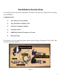
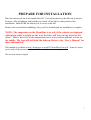
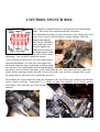
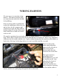
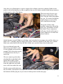
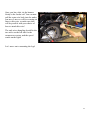
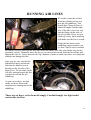
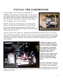
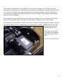
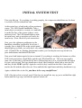
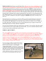
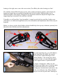
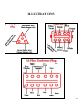
Installation Manual
Generation II Yamaha
Royalstar Venture
1999-2013
Copyright 2015 Pete Giarrusso, Inc.
D/B/A Chopper Design Services
All Rights Reserved
2
Table of Contents
INTRODUCTION .................................................................................... 4
WARRANTY ............................................................................................ 5
INSTALLATION INSTRUCTIONS ...................................................... 6
COMPONENTS: .................................................................................................... 6
PREPARE FOR INSTALLATION ...................................................................... 7
CONTROL SWITCH BOX ................................................................................... 8
WIRING HARNESS .............................................................................................. 9
LEG & MOUNT ASSEMBLIES ......................................................................... 13
RUNNING AIR LINES ........................................................................................ 14
INSTALL THE COMPRESSOR ........................................................................ 15
INITIAL SYSTEM TEST .................................................................................... 17
MOUNT PROXIMITY SENSOR ....................................................................... 18
WIRE ROUTING ................................................................................................. 19
FINISHING UP ..................................................................................................... 21
FINAL ADJUSTMENTS & MAINTENANCE MODE................................................... 23
MAINTENANCE MODE ................................................................................................ 23
WHEEL ADJUSTMENT ................................................................................................. 24
TEST RIDE ........................................................................................................... 27
ILLUSTRATIONS ............................................................................................... 29
HARDWARE LIST .............................................................................................. 30
3
Introduction
This manual covers installation of the Generation II LegUp LandinGear system by Chopper
Design Services. This system should only be installed by a qualified technician, or those with
above average mechanical skills. If you are not SURE that you can perform this installation,
please contact us and we will help you find a qualified shop to assist you.
While the Generation II System holds your bike upright very well, you are STILL responsible
for balancing the bike! The system WILL relieve you of some of the weight of the bike and
help you avoid balance problems as you approach a stop, maneuver at slow speeds, and back
the bike up.
Improper installation will void your warranty, so please be very careful!
Thanks for choosing LegUp!
4
Warranty
Chopper Design Services warrants the LegUp system for a period of one year from date of
purchase. This warranty covers replacement parts and/or manufacturer defects. Incidental
damages or costs are the responsibility of the purchaser.
Defective parts are to be returned to Chopper Design at the address below. Purchaser must
contact Chopper Design to receive a Return Material Authorization, prior to returning defective
parts to Chopper Design.
Abuse, improper installation or use, collisions or accidents, are not covered under this warranty.
Replacement parts for this type of damage are available through Chopper Design.
Users of the LegUp system agree that Chopper Design is NOT responsible for personal injuries
or damage to property arising from the use of the system. While we believe this system to be
safe and reliable, the user is advised that use of LegUp is done so at the users’ own risk. Use of
the system implies agreement to the above statements. If you can’t agree with the above,
Chopper Design and its dealers would be happy to refund your full purchase price, before you
install the LegUp System.
Chopper Design Services
1365 Bennett Dr. #101
Longwood, FL 32750
407-834-5007
[email protected]
5
Installation Instructions
The LegUp® system has many components. Pleased be sure you have them all before starting
your installation.
COMPONENTS:
1)
Wire Harness W Switch Box
2)
Leg and Mount Assembly (L/R)
3)
On-board Computer Module
4)
Proximity Sensor
5)
Saddlebag Mounted Compressor System
6)
Hardware Bag
If you believe you are missing any parts, please contact Chopper Design at 407-834-5007, and
we will rectify the situation.
Figure 1
6
PREPARE FOR INSTALLATION
Place the motorcycle on an acceptable bike lift. You will need to keep the bike on its wheels
for most of the installation, and jack the rear wheel off the lift for some portion of the
installation. Make SURE the motorcycle is secure on the lift!
Remove the seat and both saddlebags; they won’t be needed until the installation is complete.
NOTE: The suspension on the RoyalStar is so soft, if the wheels are deployed
without the rider’s weight on the seat, the bike will lean on one wheel or the
other! This is how it is as the suspension rises a few inches without a rider in
the saddle. The legs will still hold the bike up. Refer to the ‘User’s Manual’ for
more information.
This manual is available at http://landingear.com/pdf/G2installRoyalstar.pdf . It may be easier
to see some of the pictures in color there!
We are now ready to begin!
7
CONTROL SWITCH BOX
The switch box should already be mounted to a black mounting
plate. The switch box mounts under the left mirror.
First dismantle the plug, so you can run the wires where they need
to go. Next, remove the left mirror, and the adapter. Slide the
adapter through the
hole on the switchbox
plate, and with some
Loctite, tighten the
adapter back down to
the hand control. Make
sure the switchbox is square to the bike before final
tightening. You can then reinstall the mirror.
You will need to run the wire over the clutch perch,
down the handlebar, over the top of the triple-tree,
then back under the edge of the tank to end up under
the seat area. We removed the bottom clip that holds
the plastic cover in front of the tank, so we could slide the wire from under the bars, under the
plastic before running it under the tank. You need to make sure you have enough slack to put
the plug back on, after the wire is under the seat area!
Reassemble the 8-pin connector using the diagram at the top of the page, making sure that the
colors match perfectly. Sometimes it is smart to plug the harness in to verify perfect
reassembly. Now onto the rest of the wiring
harness!
8
WIRING HARNESS
The next step is to route the wiring
harness. The harness and the plugs
are routed mostly under the seat and
left saddlebag.
First we need to make a small notch
in the left saddlebag to allow the wire
and air lines for the computer and
compressor to enter the bag without
being crushed. We used a rotary tool,
but a round file or small saw would
work as well.
The notch is positioned as seen in the photo. It is approximately 1/2” wide and just over 3/4”
long. Notice that it extends just below the lip that the top cover mates to. This is very important!
Otherwise the lid would crush the wire. It goes without saying that this notch in on the inside, or
back-side of the bag. Set the bag aside as we won’t need this until the very end.
Next we remove the
rubber plug behind the
battery on the left side to
allow us to run the
harness under the seat
from the back of the bike.
The 8 pin connector
should have been
disassembled for you, and
we usually run the 3 pin
plug, then the 8-pins of
wire for the 8-pin
connector, then the two
hoop connectors (opening
the fuse holder makes it
easier), and the two spade plugs through the hole in that order.
9
Once these are all through we want to connect the red hoop connector with fuse holder to the
positive side of the battery (we like to pull the fuse out for safety), and the black hoop connector
to the negative side of the battery.
The next step is for us to get
the power connections to the
bike. Find the white plug under
the seat. We need to install the
purple plugs over two of the
wires attached to the plug.
Wrap one of these snaptogether connectors around the
blue wire, and another around
the black. These connectors
will snap closed and become a
spade connector we attach our
power leads to.
On the harness, you will find two red plugs; one is attached to an orange wire and the other to a
black wire. Carefully plug the orange wire on the connector attached to the blue wire, and the
black one on the black wire from the bike. Make sure you don’t have these backwards!
For you technical types, the
blue wire is switched 12 volts
for the taillight, and the black is
ground. This is how the system
is initialized once the key is
turned on.
We now want to get the three
pin plug that is attached to the
speed sensor (little yellow
block on a metal bracket) up
from the right side rear brake
area, to the area under the seat.
Put the sensor and bracket near
the rear brake, and run the wires up to the seat area. You should be able to squeeze this up from
the bottom with the plug on, as you can see in the picture on the next page.
10
We ran the wire along the
swing arm and it will be
tied along the brake line
later. Leave a bit of slack as
you aim the wire up to the
right side of the battery
under the seat.
If you had to take the plug
apart to run these wires,
reassemble the plug, but be
careful. This is a three
position plug, so it is VERY
easy to wire incorrectly.
Refer to the diagram here
and take note of the wires are on the sensor side. It may be easier to plug this into its mating
plug to verify the colors.
NOTE: We will mount this bracket in this area later, but
making sure you have enough wire to mount it and that
the extra slack is pulled to the under seat area!
We should be able to plug in all the connectors under the seat. No
need to clean it all up, just plug in the 8 pin plug from the
handlebar switches to its mate and the three pin plug to its’ mate.
Next pull the wires on the
left side as shown here, and
tie them to the fender rail
loosely. We will tie our air
lines to them as we get
ready to put the bag back
on. We want about 17” of
wire extending from the rear
upright to the 12-pin plug
on the harness.
11
Once you have this, tie the harness
firmly to the fender rail. You can now
pull the extra wire back into the under
seat area. Later we will be securing air
lines to this wire, so make sure that
will be possible with your choice of
how to attach this wire!
The only wires dangling should be the
two wires on the left side for the
compressor system, and the speed
sensor on the right!
Let’s move on to mounting the legs!
12
LEG & MOUNT ASSEMBLIES
In order to mount the legs, we must first remove
the passenger floorboards. This is accomplished by
removing the c-clip on the end on the pin that
holds the floorboards on. Once the c-clip is
removed, slide the pin out. You will find a small
ball bearing and a plate on one side of the
floorboard that will become free as the floorboard
comes loose.
We don’t need any of these pieces, but you may
wish to keep them if you remove the system in the
future.
With the floorboard off, find the appropriate leg
for the side you are working on (right side
shown here), and gently slide it on, allowing the
ears from the floorboard mounts to slide through
the slots in the leg. This is a tight fit, so it may
take some wiggling.
Once the leg is mounted, find the long 5/16”
(3.25” at least) bolt, and run it through the
mounts on the bike and the legs. Cap the bolt
with a lock nut.
Once the bolt is tight, we want to slowly
tighten the 2 Allen bolts on the top of the
mount, until they are pressed firmly against
the floorboard mounts of the bike. Once these
are VERY firm, tighten the lock bolts as
shown here. These bolts keep the legs planted
firmly to the ground! They should be
checked on a regular basis! Grab the leg and
give it a shake; it should be very tight to the
bike.
Repeat this procedure on the other side. We
will mount the floorboards later!
Let’s run the air lines!
13
RUNNING AIR LINES
We need to route the air lines
from the cylinders to the area
near the left saddlebag. You
should find 2 long air lines of
identical lengths. On the right
side of the bike, press one end
into the fitting on the back of
the air cylinder. These press in
relatively easily, but a small tug
will make sure the line is seated.
Guide the line down to the
saddlebag support bracket you
see here. Start a wire tie around
the bracket loosely, and slide the hose up toward the battery box (like you did the plug for the
proximity sensor). Manually lower the leg so you can see how much slack the line needs, and
tighten the wire tie. Lower and raise the leg a number of times to make sure there is no bind and
nothing can damage the line.
Once you are sure, run the line
behind the battery and out the
hole that the harness travels
through on the left side of the
battery box. Do the same on the
left side, and again push the line
out the hole toward the left
saddlebag.
As you can see here, we then
neatly tie the air lines to the
main harness running toward the
saddlebag.
These are air lines, so tie them off snugly. Careful though; too tight could
restrict the air flow.
14
INSTALL THE COMPRESSOR
The first thing we need to do is to reinstall the left
saddlebag. Once the bag is installed, make sure the slot you
cut is big enough for the wires and air lines to get into the
bag with the top closed without damaging anything. If need
be, make the slot a bit deeper or wider. If you are happy
that everything is safe, we can continue.
Find the compressor, as shown here. We need to remove
the top, as it won’t be needed until the very end! We do
this by removing the three nylon nuts on the top of the
plate. These are only hand tight and they will be reinstalled
without any tools as well.
Once the top is off the compressor should look something like the picture below. We want to
slowly install the compressor in the bag. The silver valve system goes toward the back, and the
compressor is slid back almost as far as it can go. It is mounted on rubber feet to avoid damage
to the bag, and to reduce vibration. The picture here shows the compressor plugged in, with
lines attached.
NOTE: We supply you with
some black rubber edging. It
may be used if after installing
the compressor you find the
metal edge touches the hard
bag somewhere causing a
vibration. If once the
compressor is on, you need to,
cut pieces of the rubber and
slide it on the metal where
needed to keep the vibration
down.
Once the compressor is in place,
the air lines should be attached
to the fittings you mounted in
the saddlebag. We took the extra
airline, and wound it into a circle and tied it with wire ties. Then we connected the lines to the
compressor system.
15
The compressor should feel very stable in its new home. Assuming it does, this would be a
good time to run the big wire into the bag, and connect the computer (seen below with the label
on it) to the 12 pin plug, and connect the compressor to the 8 pin plug. We left a loop in the
wire and air lines before they entered the bag so water will drop off this bundle rather than be
guided into the saddlebag.
These plugs can only be attached one way, and we are going to leave the computer and wires
just loose in the bag for now. I promise we will make it all pretty before you are done.
In preparation for testing the system, if you haven’t already, hook the negative battery terminal
and the lead from our power connection, up to the negative battery terminal (don’t worry that
the proximity sensor is
still lying on the lift!).
This is just a tease, but
this is how the saddlebag
will look when you are
done!
Now let’s test the system.
16
INITIAL SYSTEM TEST
Turn your bike on. If everything is working properly, the compressor should turn on for about
6 seconds to fill the onboard air tank.
At this point, have a look at the yellow proximity
sensor. The LED Should Not Be Lit. Take a
metal object (screwdriver, wrench, etc) and hold
it on the flat face of the sensor (it has a circle
embossed in it). The LED should light up with
the metal near, and go out when you move the
metal away. If not, check all your connections.
Next, press the rightmost pushbutton on the
handlebar switchbox, and hold it for at least 3
seconds. One or both LEDs on the switch panel
should light up or blink; we really don’t care which at this point. If this occurs, you are doing
well. If both LEDs are flashing (maintenance mode) you can skip the next step which is to
press both buttons until both LEDs flash.
Next press both buttons again for just an instant! If everything is working, the bottom or yellow
LED on the switch box should flash, and the top LED should be out. The next step requires
some care. If the bike is still on the lift, have a helper hang on to it as you touch the left button
for just a split second. The legs should move down, likely until the wheels hit or miss the lift,
and they do this VERY quickly! Again be careful as they could lean the bike if one wheel
touches the lift and the other does not. Press and hold the right button and they should move up.
Again; with the bike on the lift, you have to be very careful here!
If all of the above has occurred, great! If the legs are not all the way up, press and hold the right
button until the legs stop, and turn the ignition switch off!
17
MOUNT PROXIMITY SENSOR
This step is crucial!! Understand it before starting. The proximity sensor tells the system
how fast the bike is traveling. The
proximity sensor mounts to the bolt that
attaches the rear brake to its mount.
Remove this bolt, install it through the
bracket and reinstall the bolt semi-tight,
so the bracket can be moved if need be
(a little Locktite please!). You need to
jack up the back wheel or have the bike
on the ground so we can spin the wheel
to test the sensor and its placement.
Make sure the bike is in neutral.
The sensor will track the rotor bolts on
the rear wheel as it spins, and is to be
mounted 5MM away from the bolts or
closer. Look at the picture here. Once
the bracket is mounted, turn the key to
the ‘ON’ position, spin the wheel or roll the bike and watch the behavior of the sensor as the
bolts pass it.
The LED on the sensor should be off when no bolt is passing the sensor, and the LED (picture
next page) should light when a bolt passes by the sensor. Play with this by rotating the wheel
back and forth while adjusting the bracket in, out, left or right until the light blinks consistently.
Once you feel you have the right place, tighten the bracket down and slowly rotate the wheel.
Every time a bolt passes, the light should get bright when the bolt is nearby and off after it
passes.
If this is not happening, you may need to get the sensor a bit closer to the bolts (5MM is a very
small distance!). If you have to move the sensor closer, just loosen the bolt again, and re-adjust
the sensor. No matter what you need to do, you MUST make sure that as the wheel turns, the
light works as described above! Once you are certain, tighten the bracket down very firmly!
Re-check that everything functions properly by spinning the wheel past all 6 rotor bolts and
verifying that the LEDS changes as described above. The automatic retraction of the legs as
well as their deployment RELIES on this sensor being placed perfectly!
18
19
WIRE ROUTING
Once satisfied with the mount, make sure that
the wire runs down the brake line, and leave
some slack as it goes up under the seat. The
slack is so the wheel travel doesn’t have a
negative effect on the wire. Pull all the excess
proximity sensor wire under the seat and we
will tie it up neatly. Just make sure you route
this safely and tie it off securely!
Your wire from the handlebar should already be under the seat, tied off to the handlebar neatly
from the switch to the triple tree, and
secured safely under the tank. Now is
a good time to tie up all the wires
under the seat. First make sure you
have all excess slack pulled under the
seat. We loop our wires, tie the
excess as a bundle, make sure they
don’t interfere with the seat, and tuck
them in as shown here.
Next, we need to make sure the
compressor plug is attached and
tucked in as we install the top. Find
the L-shaped metal top that you
removed from the compressor earlier.
The top mounts with the two holes
toward the back of the bag, with the single hole toward the front. It is a tight fit, so slanting it
into the bag is best.
As you work the top over the 3 aluminum standoffs, make sure the computer and plug
(sometimes it is easier to unplug the computer until the top is set) are coming through the
curved cutout, as the plug and computer will sit on top of the compressor system. Once the top
is fitted, find the 3 nylon nuts and screw them on the three posts to secure the cover. These are
plastic nuts so no wrench is required here.
20
When complete, you want to Velcro the computer onto the top and make sure the plug (the
compressor plug stays UNDER the top) and wires look something like this. Our main
concern here is to give you as much of the saddlebag as possible, and make sure the wires and
components are not going to be chaffed or damaged.
21
FINISHING UP
Now it is time to reinstall everything you took off, and do final checking of everything!
Reinstall the seat making sure all your wires are routed neatly, tied off nicely and don’t interfere
with the seat installation. We left the right saddlebag off until we test drove the bike. Once you
are sure the speed sensor is functioning properly, you can install that bag.
We need to install the
floorboards. Find the supplied
3/8” X 3” Allen bolts and lock
nuts, and install a floorboard to
the empty holes on the top of
the leg mounts.
NOTE: These boards will
NOT be able to be flipped
up any longer! We decided
that since the wheels
would be in the way even if
the boards could be flipped
up, we would not raise the
floorboards another inch
just to allow them to pivot on these pins!
Once this is accomplished, we should get the bike on the ground, and with a helper, cycle the
wheels up and down a few times, having your helper make sure the air lines are not being
scuffed or are over tight, and that the wires are out of the way of anything that could damage
them.
Double-check all your bolts for tightness. Now we can dial in the legs, and adjust the wheels if
needed.
LEAKS!
This system uses air, and air loves to leak! The fittings we use are tested for leaks before
shipping, but we have a few simple tests to make sure you have no leaks or just insignificant
ones if any.
Set the wheels down and leave the system on. Put the kickstand down, and turn the bars all the
way left.
22
If the compressor makes noise more than once every two minutes, you may have a leak at the
lines that connect to the compressor or the tank fittings. Some soapy water will tell you where
(you will need to remove the compressor top to test for these leaks).
Assuming the compressor doesn’t lose enough air to kick on after 2 minutes, you should be
fine.
You can turn the bike off, and wait to see if in 5 minutes the bike is not as stable as it was when
the wheels were first lowered. If it lasts the 5 minutes and is still very stable, you could still
have a leak, but not one that would be a problem on the road!
REMEMBER: Royalstars will NOT sit on both wheels without a rider in the saddle.
You can still test that the wheels are firm without a rider; just understand that only
one wheel at a time will be in contact with the ground. Sit on the bike, and both
wheels will touch!
Leave the bike on its wheels overnight (again kickstand down, bars full left in case the legs lose
a lot of air; the bike will land on its stand). If in the morning, the bike is still stable you have no
leaks.
If there are leaks, the fittings on the air cylinders would be the first for the soapy water check,
with the two small line fittings on the compressor next! If you need help with these, please feel
free to call us at (407) 834-5007.
FINAL ADJUSTMENTS & MAINTENANCE MODE
The next two sections are typically NOT needed. We include them to document your system
thoroughly, but MOST people will never need to use either section.
MAINTENANCE MODE
NOTE: Maintenance mode is a procedure that ‘TEACHES’ the computer how
much pressure to use when it lowers the wheels and how much pressure to
release when raising the wheels. We always set this at the factory; ALWAYS!! We
include this procedure in case it is ever needed in the future. Please skip this
section unless you have been instructed to reset the system by Chopper Design.
Turn the ignition to Accessory and start the LegUp System (hold right button for 3 seconds).
The system should be set at the factory for proper pressure, but some wheel adjustment may be
needed. If it has been determined that ‘Maintenance Mode’ is needed, Sit on the bike, and hold
it level. If both lights on the switch box are flashing, the system is in maintenance mode. If not,
23
PRESS & HOLD both buttons until all lights flash. (Do your best to press both buttons at the
same time so the system doesn’t respond to what it thinks is a request to lower the legs) Once
flashing, hit both buttons for an instant to get the system in the ‘DOWN’ setting mode (lower,
yellow LED flashing). Touch the left button briefly; the wheels should go down immediately.
(This is VERY quick, don’t be startled!) Using very short pushes of the left button, press and
then feel the stability of the bike. If it feels firm enough, try leaning the bike a bit. If the wheels
return the bike to upright, there is likely enough pressure. Put your feet on the floorboards; the
bike should stand on its’ own. Rock the bike a bit left and right, being prepared to put your feet
down. If the bike continues to come back to upright, the DOWN stop is now set and we can
move on.
Hit both buttons for a moment to get into the ‘UP’ stop mode (Usually hitting the left button
just before the right assures that air is not released!) The top LED should now be blinking.
Press and hold the right button to raise the legs. Listen as the air evacuates; once it is quiet, let
go of the right button. The UP stop is now set! Hit both buttons when complete, Both LEDs
should light, and you are done with these adjustment.
Now press the left button and the legs should lower; again this is fast and loud. The bike should
be held up firmly! Hit it again and the legs should retract. If you are satisfied with these limits,
you have successfully installed the LegUp System.
WHEEL ADJUSTMENT
The LegUp GEN II system is typically set up at the factory for the height of your bike. The
system is VERY height dependent! If after testing the initial installation, the bike does NOT feel
stable, the wheel system MAY need to be adjusted to the height of your bike. Remember; the
Royalstar has a suspension that rises substantially without any weight on the seat, so the
stability needs to be checked with a rider on board. DO NOT make any changes unless the
stability we expect is NOT present! If you feel you need to adjust the height/length of the wheel
holders, please read this ENTIRE section before starting the process. If you need help, please
contact Chopper Design at 407-834-5007.
If you are happy with how stable the bike feels,
you can skip this section, and move on to a test
ride! If you are not sure, or you skipped
‘maintenance mode’ as instructed, a good test is
to bring the wheels down, put the kickstand down,
and lean (or try to) the bike on its kickstand while
sitting on the bike. If the bike comes back to
center without your help, or you put your feet on
the boards and can bring the bike up by just
24
leaning to the right; move on to the next section (Test Ride), the wheel settings are fine!
The stability of the GEN II LegUp system, relies on the pneumatic actuator, when deployed,
being at an angle that is forward of perpendicular for best results! Different bikes are at
different heights, and Chopper Design uses an ingenious method to adjust the length of the
supporting legs to maximize the stability it affords.
Typically, we will send the ‘Leg Assemblies’ set up for perfectly for your bike. In the event
your bike is at a different height than stock, the information and adjustments that follow may be
required.
Below, we show you the wheel holders which should help clear up any confusion you may have
about the wheel holders and their adjustments.
On each supporting leg, you will find two
bolts down near the end by the wheels.
The two bolts control the angle of the
‘Wheel Holders’. By moving the wheel
forward or back, we can tailor the length
of the support arms to a particular bike.
A helper is handy here. Make sure the
wheels are up. Make note of exactly which
two holes the bolts are in. Loosen the
locking nuts from the back and remove the
bolts; you will notice the ‘Wheel Holder’
can pivot on the big axle bolt. Starting on
25
the left side of the bike, move the bolts one hole counter-clockwise. Go to the right side and
move them one hole clockwise. Loosely fit the nuts (no need to final tighten them at this point).
Lower the legs. Is the bike more or less stable? If it is more stable, and you can sit on the bike
and rock it back and forth without it leaning over you are done. If not, remove the bolts again,
and move them in the opposite direction two holes, and retest. If everything is fine, final tighten
the lock nuts and you are done.
If you need to, you can move the wheels from the lowest hole, up one hole. You can remove the
wheel holders, turn them over (strap up instead of down for example) and install them on the
other side of the bike. You can move the big axle from the low to the high hole. All these
techniques take patience, but allow significant flexibility to tailor the system to your bike. On
the next page we show you some examples. Normally you do not need to do ANY of these
adjustments, but if you need to, we wanted to teach you the methods at your disposal.
26
TEST RIDE
Get the bike to a clear paved mostly level area where you can test ride it. Start the bike, turn on
the LegUp system and lower the legs. The first test should be done in a straight line. Put the
bike in gear and slowly accelerate. You may notice that the bike tends to want to steer a small
amount left or right. This is normal unless it is severe. Effectively, you are driving a trike, and
steering is done with the handlebars NOT by leaning. Once underway, (we recommend you
keep your thumb near the left button, and press it to raise the wheels if there are any surprises)
the top LED should flash at around 6 MPH, meaning the legs are retracting. It is difficult to
lean on one wheel or the other as you leave, so you may wish to raise the wheels manually if the
bike is steering due to uneven pavement.
Assuming the legs are retracted, you should try to deploy the wheels. As you come to a stop,
the Green LED should be on. As you slow down (almost stopped), the Yellow LED should
illuminate at the proper speed. Once it does (sometimes hard to see), hit the left button and put
your feet down near the ground. The top LED should flash and the wheels should deploy
almost instantly underneath you! Make sure you are ready to balance the bike, though you
likely won’t have to! Immediately after the wheels touch the ground, the bike should be
supported reasonably, but the cylinders can take up to 6 seconds to get completely filled. Make
sure you balance the bike as this occurs. The slower you are going when deploying the wheels,
the smoother the transition will be from wheels up to wheels down. Practice these maneuvers
until you are comfortable with the wheel adjustments and the system operation.
SEMI-AUTOMATIC DEPLOYMENT: Another way to deploy the legs is semi-automatically.
First we must be SURE that the proximity sensor is working properly or the wheels could come
down at higher speeds than we wish. If you are travelling at a speed over 10 MPH, AND the
yellow light (bottom) on the handlebar control is out, hit the left button. The bottom or yellow
LED should start to flash. When you slow down to around 5MPH the wheels will deploy (see
the red/green flash on top LED). Again prepare to put your feet down. IF the lower LED is lit at
a speed over 10 MPH, don’t hit that button; see caution below!
NOTE: The bottom LED Should not be LIT SOLID if the bike is travelling over
10MPH! In the event it is, the wheels will deploy instantly if you try to set them as
above; this is dangerous! You MUST re-visit the sections on testing the proximity
sensor. You should always be aware that this light should NOT be on if you are
traveling at speed, and ‘Arming’ the system for deployment should only be
attempted if the lower LED is Not Lit! Please see the User Manual for more
information on Proximity Sensor Failure!
27
The next thing to try is to make a turn from a dead stop with the wheels down. As soon as you
start the bike moving, turns can only be made by using the handlebars. The LegUp system is too
strong to allow a great deal of lean with the wheels down! If you need to make a turn shortly
after departing from a stop, raise the wheels manually (left button) and you will get complete
control again.
The next thing to try is slow speed maneuvering with the wheels lowered. If you keep your
speed down, most slow speed maneuvers can be accomplished with your feet up, keeping in
mind that at about 6 MPH the wheels will come up automatically! You can try full lock turns in
both directions and the bike should stay upright with your feet up.
Understand; it is always a good idea to keep your feet near the ground during these maneuvers
if you can. A mechanical failure or a wheel in a pothole could upset the bike.
Because the wheels are right behind your legs when they are down, we recommend not trying to
push with your feet to move the bike forward. Use the engine and keep your feet out of the way;
this way the legs don’t bite at your heels as the floorboard always have! Backing up using your
feet works fine and the chore of balancing the bike is taken care of for you.
Practice, practice, practice!! Enjoy your LegUp System!
28
ILLUSTRATIONS
29
HARDWARE LIST
(2) 5/16-18 X 3.25” Allen Bolts with Lock Nuts
(2) 5/16-18 X 3.00” Allen Bolts with Lock Nuts
(4) ¼-20 X 1.125” Allen Bolts with Jam Nuts
(4) Rubber Spacers
Hardware Bag with ties, Rubber bumpers installed on plate, etc.
30