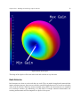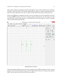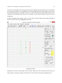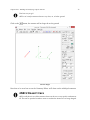
1
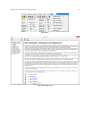
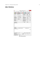
4NEC2 Definitive Guide
Mark Schoonover KA6WKE
©2015 Mark Schoonover KA6WKE
I’d first like to apologize to all my junior and senior high school English teachers when I told them
writing isn’t fun. If it wasn’t, this book would have never been written.
I’d like to thank my wife and children for tolerating this great hobby of Amateur Radio despite
setting off smoke alarms and other RFI that infiltrated their computers, the Donald Duck voices,
and that incessant beeping I love as Morse Code.
I’d like to thank my long time friend Paul Cater WD8OSU for the time we’ve spent together bending
the ionosphere to our will. I learned so much from you thank you for being such a great friend.
Another long time friend is Otto Tune KV7J (SK) who really pushed my CW skills hard during
many MARS CW nets and taught me the fine art of “Front Panel Troubleshooting”.
Nearly last but not least are my parents for introducing me to Dennis Langheir K2CEC (SK) that
sparked my love for all things electronics and especially Amateur Radio. Sorry about hearing Morse
Code at 2 AM out of your alarm clock radio when I was a teenager. The DX was worth it!
This book is dedicated to Dennis Langhier K2CEC (SK) and Edward “Otto” Tune KV7J (SK).
This is a “90 minute at a time publication”
Contents
Introduction . . . . . . . . . . . . . . . . . . . . . . . . . . . . . . . . . . . . . . . . . . . .
Conventions . . . . . . . . . . . . . . . . . . . . . . . . . . . . . . . . . . . . . . . . . . .
PC Requirements . . . . . . . . . . . . . . . . . . . . . . . . . . . . . . . . . . . . . . . .
1
1
2
About the Author . . . . . . . . . . . . . . . . . . . . . . . . . . . . . . . . . . . . . . . . .
3
Chapter One - Installation . . . . . . . . . . . . . . . . . . . . . . . . . . . . . . . . . . . .
Downloading 4NEC2 . . . . . . . . . . . . . . . . . . . . . . . . . . . . . . . . . . . . . .
Installing 4NEC2 and Configuration . . . . . . . . . . . . . . . . . . . . . . . . . . . . . .
4
4
4
Chapter Two - Learning Your Way Around
Finding Help . . . . . . . . . . . . . . . . .
Main Window . . . . . . . . . . . . . . . .
Geometry Window . . . . . . . . . . . . .
Pattern Window . . . . . . . . . . . . . . .
3D Viewer Window . . . . . . . . . . . . .
Smith Chart . . . . . . . . . . . . . . . . .
Geometry Builder . . . . . . . . . . . . . .
.
.
.
.
.
.
.
.
.
.
.
.
.
.
.
.
.
.
.
.
.
.
.
.
.
.
.
.
.
.
.
.
.
.
.
.
.
.
.
.
.
.
.
.
.
.
.
.
.
.
.
.
.
.
.
.
.
.
.
.
.
.
.
.
.
.
.
.
.
.
.
.
.
.
.
.
.
.
.
.
.
.
.
.
.
.
.
.
.
.
.
.
.
.
.
.
.
.
.
.
.
.
.
.
.
.
.
.
.
.
.
.
.
.
.
.
.
.
.
.
.
.
.
.
.
.
.
.
.
.
.
.
.
.
.
.
.
.
.
.
.
.
.
.
10
10
12
25
41
58
62
67
Chapter Three - Building and Analyzing a Dipole Antenna
A Word or Three about Theoretical VS Real Antennas . . .
Using the Geometry Editor . . . . . . . . . . . . . . . . . .
Analyzing the Results . . . . . . . . . . . . . . . . . . . . .
Conclusion . . . . . . . . . . . . . . . . . . . . . . . . . . .
.
.
.
.
.
.
.
.
.
.
.
.
.
.
.
.
.
.
.
.
.
.
.
.
.
.
.
.
.
.
.
.
.
.
.
.
.
.
.
.
.
.
.
.
.
.
.
.
.
.
.
.
.
.
.
.
.
.
.
.
.
.
.
.
.
.
.
.
.
.
.
.
.
.
.
.
.
.
.
.
.
.
.
.
.
69
69
71
83
90
Chapter Four - 4NEC2 Editors
4NEC2 Geometry Editor . .
NEC Editor (New) . . . . . .
NEC Editor . . . . . . . . .
Notepad Editor . . . . . . .
.
.
.
.
.
.
.
.
.
.
.
.
.
.
.
.
.
.
.
.
.
.
.
.
.
.
.
.
.
.
.
.
.
.
.
.
.
.
.
.
.
.
.
.
.
.
.
.
.
.
.
.
.
.
.
.
.
.
.
.
.
.
.
.
.
.
.
.
.
.
.
.
.
.
.
.
.
.
.
.
.
.
.
.
.
92
92
92
92
92
Chapter Five - Geometry Builder . . . . . . . . . . . . . . . . . . . . . . . . . . . . . . . .
93
Chapter Six - Optimizer . . . . . . . . . . . . . . . . . . . . . . . . . . . . . . . . . . . . . .
94
Chapter Seven - L/Pi/T Matching . . . . . . . . . . . . . . . . . . . . . . . . . . . . . . . .
95
.
.
.
.
.
.
.
.
.
.
.
.
.
.
.
.
.
.
.
.
.
.
.
.
.
.
.
.
.
.
.
.
.
.
.
.
.
.
.
.
.
.
.
.
.
.
.
.
.
.
.
.
.
.
.
.
.
.
.
.
.
.
.
.
.
.
.
.
.
.
.
.
.
.
.
.
.
.
.
.
.
.
.
.
.
.
.
.
.
.
.
.
.
.
.
.
.
.
.
.
.
.
.
.
.
.
.
.
.
.
.
.
.
.
.
.
.
.
.
.
.
.
.
.
.
.
.
.
.
.
.
.
.
.
.
.
.
.
.
.
.
.
.
.
.
.
.
.
.
CONTENTS
Chapter Eight - Graphing with gnuplot . . . . . . . . . . . . . . . . . . . . . . . . . . . . .
96
Chapter Nine - Using ItsHF & VOACAP
Models . . . . . . . . . . . . . . . . . .
Area Coverage . . . . . . . . . . . . . .
Point-to-Point . . . . . . . . . . . . . .
.
.
.
.
.
.
.
.
.
.
.
.
.
.
.
.
.
.
.
.
.
.
.
.
.
.
.
.
.
.
.
.
.
.
.
.
.
.
.
.
.
.
.
.
.
.
.
.
.
.
.
.
.
.
.
.
.
.
.
.
.
.
.
.
.
.
.
.
.
.
.
.
.
.
.
.
.
.
.
.
.
.
.
.
.
.
.
.
.
.
.
.
.
.
.
.
.
.
.
.
.
.
.
.
.
.
.
.
.
.
.
.
97
97
97
97
Chapter Ten - Verticals
Very Short Verticals .
Quarter Wave . . . .
Half Wave . . . . . .
5/8 Wave . . . . . . .
.
.
.
.
.
.
.
.
.
.
.
.
.
.
.
.
.
.
.
.
.
.
.
.
.
.
.
.
.
.
.
.
.
.
.
.
.
.
.
.
.
.
.
.
.
.
.
.
.
.
.
.
.
.
.
.
.
.
.
.
.
.
.
.
.
.
.
.
.
.
.
.
.
.
.
.
.
.
.
.
.
.
.
.
.
.
.
.
.
.
.
.
.
.
.
.
.
.
.
.
.
.
.
.
.
.
.
.
.
.
.
.
.
.
.
.
.
.
.
.
.
.
.
.
.
.
.
.
.
.
.
.
.
.
.
.
.
.
.
.
.
.
.
.
.
.
.
.
.
.
.
.
.
.
.
.
.
.
.
.
.
.
.
.
.
.
.
.
.
.
.
.
.
.
.
.
.
.
.
.
98
98
98
98
98
Chapter Eleven - Multi-Element
Beams . . . . . . . . . . . . .
Log Periodics . . . . . . . . .
Loops . . . . . . . . . . . . .
.
.
.
.
.
.
.
.
.
.
.
.
.
.
.
.
.
.
.
.
.
.
.
.
.
.
.
.
.
.
.
.
.
.
.
.
.
.
.
.
.
.
.
.
.
.
.
.
.
.
.
.
.
.
.
.
.
.
.
.
.
.
.
.
.
.
.
.
.
.
.
.
.
.
.
.
.
.
.
.
.
.
.
.
.
.
.
.
.
.
.
.
.
.
.
.
.
.
.
.
.
.
.
.
.
.
.
.
.
.
.
.
.
.
.
.
.
.
.
.
.
.
.
.
.
.
.
.
.
.
.
.
99
99
99
99
Chapter Twelve - Loops .
Single Band Loops . . .
Multiband Loops . . .
Magnetic Loops . . . .
.
.
.
.
.
.
.
.
.
.
.
.
.
.
.
.
.
.
.
.
.
.
.
.
.
.
.
.
.
.
.
.
.
.
.
.
.
.
.
.
.
.
.
.
.
.
.
.
.
.
.
.
.
.
.
.
.
.
.
.
.
.
.
.
.
.
.
.
.
.
.
.
.
.
.
.
.
.
.
.
.
.
.
.
.
.
.
.
.
.
.
.
.
.
.
.
.
.
.
.
.
.
.
.
.
.
.
.
.
.
.
.
.
.
.
.
.
.
.
.
.
.
.
.
.
.
.
.
.
.
.
.
100
100
100
100
.
.
.
.
.
.
.
.
.
.
.
.
.
.
.
.
.
.
.
.
.
.
.
.
.
.
Chapter Thirteen - Modeling Mobile Antennas . . . . . . . . . . . . . . . . . . . . . . . . 101
Chapter Fourteen - Circular VHF/UHF Satellite Antennas . . . . . . . . . . . . . . . . . . 102
Chapter Fifteen - Antenna Menagerie! .
Beverages . . . . . . . . . . . . . . . .
Rhombics . . . . . . . . . . . . . . . .
Pennents . . . . . . . . . . . . . . . . .
Discones . . . . . . . . . . . . . . . . .
Patch . . . . . . . . . . . . . . . . . . .
80M Parabolic . . . . . . . . . . . . . .
2.4 GHz Pringles WiFi Antenna . . . .
2.4GHz High Gain Loop WiFi Antenna
.
.
.
.
.
.
.
.
.
.
.
.
.
.
.
.
.
.
.
.
.
.
.
.
.
.
.
.
.
.
.
.
.
.
.
.
.
.
.
.
.
.
.
.
.
.
.
.
.
.
.
.
.
.
.
.
.
.
.
.
.
.
.
.
.
.
.
.
.
.
.
.
.
.
.
.
.
.
.
.
.
.
.
.
.
.
.
.
.
.
.
.
.
.
.
.
.
.
.
.
.
.
.
.
.
.
.
.
.
.
.
.
.
.
.
.
.
.
.
.
.
.
.
.
.
.
.
.
.
.
.
.
.
.
.
.
.
.
.
.
.
.
.
.
.
.
.
.
.
.
.
.
.
.
.
.
.
.
.
.
.
.
.
.
.
.
.
.
.
.
.
.
.
.
.
.
.
.
.
.
.
.
.
.
.
.
.
.
.
.
.
.
.
.
.
.
.
.
.
.
.
.
.
.
.
.
.
.
.
.
.
.
.
.
.
.
.
.
.
.
.
.
.
.
.
.
.
.
.
.
.
.
.
.
.
.
.
.
.
.
.
.
.
.
.
.
.
.
.
.
.
.
103
103
103
103
103
103
103
103
103
Appendix B - NEC User Manual Installation . . . . . . . . . . . . . . . . . . . . . . . . . . 104
Appendix C - Gnuplot Installation & Configuration . . . . . . . . . . . . . . . . . . . . . 105
Appendix D - ItsHF & VOACAP Installation & Configuration . . . . . . . . . . . . . . . . 106
4NEC2 Function Keys & Keyboard Shortcuts Cheat Sheet . . . . . . . . . . . . . . . . . . 107
Main Window . . . . . . . . . . . . . . . . . . . . . . . . . . . . . . . . . . . . . . . . . . 107
Geometry Window . . . . . . . . . . . . . . . . . . . . . . . . . . . . . . . . . . . . . . . 108
CONTENTS
Pattern Window . . . . . . . . . . . . . . . . . . . . . . . . . . . . . . . . . . . . . . . . . 110
Smith Chart . . . . . . . . . . . . . . . . . . . . . . . . . . . . . . . . . . . . . . . . . . . 111
Appendix A - 4NEC2 5.8.15 README File . . . . . . . . . . . . . . . . . . . . . . . . . . . 113
To install the 4nec2 package, follow the below steps. . . . . . . . . . . . . . . . . . . . . . 113
Change Log . . . . . . . . . . . . . . . . . . . . . . . . . . . . . . . . . . . . . . . . . . . . . 119
Introduction
Thanks for downloading and reading this Definitive Guide to the widely popular 4NEC2 Antenna
Modeling software. 4NEC2 is a NEC based antenna modeler and optimizer developed by Arie Voors.
This is a 3rd party book and is not connected to Arie in any way. If you find mistakes in this book,
they are all mine. :)
The sample version of the book is complete but the full version is in progress. I’m releasing the
sample version first to gauge interest in this book while I continue working on chapter 4. As chapters
or appendices are completed, they will be released as updates. All updates for the sample and full
version of this book are FREE, and it’s available in PDF, ePUB, and MOBI formats.
The full version of the book starts with chapter 4 that covers the different 4NEC2 editors. The
Geometry Editor, due to it’s complexities, warrants its own chapter. Other chapters will include
using the optimizer and matching tools, using gnuplot for high resolution graphs, using ItsHF and
VOACAP with the remaining chapters on design and analysis of various kinds of antennas such as
verticals, multi-element, loops, satellite, and a grab bag of antennas the author finds interesting.
If you’d like to give feedback, please do! There are several ways to give feedback:
Via Leanpub 4NEC2 Definitive Guide feedback¹ page.
There is a Yahoo Group dedicated to this book. It’s a closed group for discussing the book, asking
for clarifications, or taking the author to task for an egregious error!
To subscribe send an email to: [email protected]² or from Yahoo Groups
web GUI:
https://groups.yahoo.com/4nec2defguide³.
If you’re a Facebook user, you can like this book there too!
https://www.facebook.com/4nec2defguide⁴
Conventions
Selecting Menus
Directions to which menu to use is shown as Edit->Copy where the menu is left of the -> and
the menu option is to the right of the ->. Sub-menus are shown as Run->Quickly->possible. Both
menus and their options matches what is shown in the program.
¹https://leanpub.com/4nec2definitiveguide/feedback
²[email protected]
³https://groups.yahoo.com/4nec2defguide
⁴https://www.facebook.com/4nec2defguide
2
Introduction
Program Specific Text
Program specific text IE: menu text and screen output, etc will look like this Program Specific Text
a fixed monospaced font.
Warnings, Tips, Errors, Information
This is a warning!
Warning, this is a warning!
This is a tip!
Tips look like this.
This is an error.
ERROR: Antennas work the first time they’re built!
This is just info
QST, QST - Bulletin about 4NEC2 Definitive Guide.
PC Requirements
Just about all computers of recent vintage can run 4NEC2 without issues. Obviously the more
memory and CPU speed you have the faster the analysis will go and the more complex of an antenna
that can be analyzed.
Supported Operating Systems
Basic functionality was tested on the following operating systems.
• Windows XP SP3
• Windows 7 64bit
• Windows 8 64bit
Running 4NEC2 under Linux/Wine will be tested and documented in a later version of this book.
4NEC2 most likely works on Windows 32bit versions as well but the author doesn’t use 32bit versions
of operating systems.
About the Author
Mark Schoonover has been licensed since 1982 when he got his Novice license on a wager with his
dad. If he didn’t pass his Novice test, he had to mow the lawn for FREE all summer break. He got his
General license in 1983 from the now long closed FCC Field Office in San Francisco. Upon his return
from Navy active duty in 1987 he got his Advanced license. Around 2000 he got his Extra. He’s held
his call since 1982 and don’t have any plans to obtain a vanity call. He enjoys homebrewing and
contesting from his pip-squeak station in southern California.
Professionally, he has a degree in Computer Science and Software Engineering. He switched from
Electrical Engineering when the internet became publicly available. Currently he’s a Senior Systems
Engineer for a major health care provider in the United States. He’s been married to his best friend
for 23 years and they have three boys all in college. On the occasions they are being too loud, he’s
been known to launch a denial of service attack against their gaming computers!
Chapter One - Installation
Downloading and installing 4NEC2 will be covered in this chapter. Installation is straight forward
and the default settings will be used throughout this book for all screen captures. The author is using
Windows 8 64bit for this book. Screens in other operating systems may look slightly different but
otherwise 4NEC2 will function identically.
Downloading 4NEC2
4NEC2 can be downloaded from http://www.qsl.net/4nec2/⁵. This book will cover version 5.8.15
released in January 2015 and will be updated as new versions of 4NEC2 are released. There are
several different files available to download. For this book, you’ll need to download 4nec2(setup.exe)
from the left menu. If you don’t see the download menu section, scroll down. Simply right-click on
4nec2(setup.exe) and save it to your desktop or downloads folder. 4NEC2 can be installed from any
directory.
Installing 4NEC2 and Configuration
Extract 4NEC2 by right-clicking on the 4nec2.zip file and select Extract All from the flyout menu.
Double-click on the 4nec2 folder that was created, then double-click again on the Setup4nec2.exe
file. The following window will appear:
⁵http://www.qsl.net/4nec2/
5
Chapter One - Installation
4NEC2 Opening Screen
Click Next to continue and Next again to accept the default installation directory.
4NEC2 Default Installation Directory
The Start Menu window will be displayed:
6
Chapter One - Installation
Add to the Windows Start Menu
Click Next to continue. The create desktop icon window will be displayed:
Create 4NEC2 Desktop Icon
Click Next to continue. The Ready to Install window will be displayed:
7
Chapter One - Installation
4NEC2 Ready to Install Confirmation
Click the Install button to start installation. Watch the little green bar!
4NEC2 Installing
The next window to appear will be how to find the getting started and README files:
8
Chapter One - Installation
4NEC2 Getting Started & README Files
Click Next to continue. The Installation Completed window will appear:
4NEC2 Installation Completed!
Click Finish to continue. You should have the 4NEC2 Main Window, 4NEC2 Geometry Window,
and the _ReadMeFirst.txt file displayed. Read through the README file, it contains the latest
information about this version of 4NEC2.
9
Chapter One - Installation
4NEC2 Installed
On the desktop, there should be three new icons.
4NEC2 Desktop Icons
Additional 4NEC2 information is located in C:\4nec2\ directory. The _GettingStarted.txt file may
be slightly out of date but feel free to use as needed. This completes the default 4NEC2 installation.
Chapter Two - Learning Your Way
Around
Let’s work our way through the 4NEC2 user interface. Double-click on the 4nec2 desktop icon:
4NEC2 Desktop Icon
to launch the program. When first started, 4NEC2 will display two windows, the Main Window,
and the Geometry Window. Keep the Help File in mind as well.
Finding Help
4NEC2 comes with context sensitive Help. To access Help, at the point you want additional
information, press the
key. From the 4NEC2 website, there’s also a forum dedicated to the
software and can be found at the 4NEC2 forums⁶.
General antenna discussions can be found on the eHAM.net antenna forum⁷ and the QRZ.com
antenna forum⁸ as well.
There is a Yahoo Group dedicated to this book. It’s a closed group for discussing the book, asking
for clarifications, or taking the author to task for an egregious error! To subscribe send an email to:
[email protected]⁹
or from Yahoo Groups web GUI:
https://groups.yahoo.com/4nec2defguide¹⁰.
If you’re a Facebook user, you can like this book there too! https://www.facebook.com/4nec2defguide¹¹
The main source of announcements for this book are from Leanpub and will follow with the Yahoo
Group then Facebook.
⁶http://fornectoo.freeforums.org/
⁷http://www.eham.net/ehamforum/smf/index.php/board,31.0.html
⁸http://forums.qrz.com/index.php?forums/antennas-feedlines-towers-rotors.33/
⁹[email protected]
¹⁰https://groups.yahoo.com/4nec2defguide
¹¹https://www.facebook.com/4nec2defguide
11
Chapter Two - Learning Your Way Around
Help Menu
4NEC2 Main Help Screen
12
Chapter Two - Learning Your Way Around
Main Window
4NEC2 Main Window
13
Chapter Two - Learning Your Way Around
Menus
Files
File Menu
Open 4nec2 in/out file
Used to open existing 4NEC2 input or output files.
Save Output file as
Save current open 4NEC2 file to another filename.
Import Far-Field Data
Far-Field Data is used by HF propagation prediction software.
Print
Print 4NEC2 project to your printer.
Exit |
|
Quit 4NEC2.
14
Chapter Two - Learning Your Way Around
Below the Exit menu option is the most recently used file list.
Edit
Edit Menu
Input (.nec) file
Displays the 4NEC2 Graphical User Interface (GUI) window where the antenna to be modeled
is entered.
Output (.out) file
Uses the default text editor to display the 4NEC2 output file.
Settings
Settings Menu
Chapter Two - Learning Your Way Around
15
Notepad Edit | NEC editor/Geometry edit | NEC editor (new)
Sets the default editor for *.nec files. The default is NEC editor (new) but the Geometry Editor
will be mostly used in this book. The other editors will be discussed in the full version of this
book.
Auto segmentation
When checked allows long segments to automatically be broken into sub-segments. Default
is 20 segments per halfwave length.
Minimum Segments
Minimum number of segments should be no less than 10 per half wavelength.
Stepped radius corr.
Option not available.
Input Power
Input power in Watts used to calculate voltages and currents in the near field.
Char-Impedance
Characteristic impedance of the system in Ohms. Normally 50 Ohms.
Pre-defined Frequencies
Opens the default editor where frequencies are added for frequency sweeping.
Pre-defined Symbols
Constants for Pi and wire sizes. Additional constants can be added to the Freq.txt¹² file.
Show Circular-Polar
Changes the display to show circular or polar coordinate system.
Phi/azim unit | Length unit | Radius unit
Changes the units for azimuth as Phi/Theta, circular or CCW azimuth, length in meters/feet,
or radius in mm/inches (AWG) of wire elements.
The next group of settings should rarely be used and will be left at their defaults for this book.
NEC Engine
Which NEC engine to use. There are several but we’ll be using the default Nec2dXS*.exe.
¹²See Directory and File Locations Appendix.
16
Chapter Two - Learning Your Way Around
Memory Usage
Optimize memory usage for number of field points, number of sweep steps, EX/LD/TL Cards¹³,
number of SYmbols, 3D points, and patches.
Optimizer | ItsHF Settings | Other Settings
Additional analysis and 3rd party programs configuration.
Calculate
Calculate Menu
NEC output-data
Displays the Generate output data screen.
NEC Output Data
The sample version of this book will use the Far Field pattern option to generate NEC output
data. Go to Edit->Output (.out) file to view the generated output file in the configured default
editor.
Window
Opens different 4NEC2 program windows & viewers.
¹³Cards are documented in the Editors Chapter in the full version of this book.
17
Chapter Two - Learning Your Way Around
Window Menu
Context Sensitive Help
-> Opens the Main Help file.
Main
-> opens the Main 4NEC2 program window.
Geometry
-> opens the Geometry window.
The Geometry window is detailed in the Geometry Window section.
Pattern
-> opens the Pattern window
The Pattern window is detailed in the Pattern Window section.
Line Chart
-> Opens the Gain/SWR/Impedance window.
3D Viewer
-> Start/select 3D-viewer window.
The 3D Viewer is detailed in the 3D Viewer section.
Smith Chart
-> View interactive Smith Chart
The Smith Chart is detailed in the Smith Chart section.
18
Chapter Two - Learning Your Way Around
Show
Show Menu
Excite/Load info
Displays calculated information in Rectangular Form by replacing the Environment section
of the Main Window.
Excite/Load info
Polar Notation
Displays the calculated results in Polar Notation. Polar Notation can be displayed by clicking
on the Polar checkbox above the Excitation/Load results.
19
Chapter Two - Learning Your Way Around
Polar Notation
Run
Run Menu
Geometry Builder
Displays the Geometry Builder for building complex antenna and ground systems.
20
Chapter Two - Learning Your Way Around
Geometry Builder
The Geometry Builder is detailed in the Geometry Builder section.
Picture Viewer
Displays plots saved in graphic format or plot files.
21
Chapter Two - Learning Your Way Around
Picture Viewer
ItsHF
This menu section is covered in the ItsHF Chapter in the full version of this book.
Toolbar
Main Toolbar
22
Chapter Two - Learning Your Way Around
Remainder of Main Window
4NEC2 Main Window
Filename
Current NEC output file
Voltage
Feedpoint voltage in complex form. Clicking on the Polar checkbox will display this
calculation in polar notation.
Impedance
Series feedpoint impedance.
Parallel Form
Equivalent parallel feedpoint impedance.
S.W.R.50
The Standing Wave Ratio at 50 ohms feedpoint impedance.
Chapter Two - Learning Your Way Around
23
Efficiency
Overall antenna efficiency.
Radiat-eff
Actual radiation efficiency. This efficiency determines how much your antenna radiates as a
percentage of input power.
RDF [ db
] Antenna gain referenced an isotropic dipole.
Frequency
The frequency the antenna was analyzed.
Wavelength
Calculated wavelength of the analyzed frequency.
Current
Feedpoint current in complex form. Clicking on the Polar checkbox will display this
calculation in polar notation.
Series comp.
Series component in microhenries.
Parallel comp.
Parallel component in microhenries.
Input power
The applied power in watts from the transmitter as measured at the feedpoint of the antenna.
Structure loss
Power in microwatts (10-6 ) that’s lost due to the materials used in the concstruction of the
antenna.
Network loss
Power in microwatts (10-6 ) that’s lost due to the matching network at the antenna feedpoint.
Radiat-Power
Amount of power in watts that’s radiated by the antenna.
Environment
Large textbox that displays the type of environment the antenna is analyzed in. This
information can change depending if the Loads checkbox is checked.
Comment
Additional information contained in the comment section of the NEC input file. This
information can change depending if the Loads checkbox is checked.
Chapter Two - Learning Your Way Around
24
Seg’s/patches
The number of subsegments or patches the antenna has been divided into for analysis.
Pattern Lines
Number of lines calculated for all the segments.
Freq/Eval steps
Displays the number of frequency or evaluation steps. Analysis at a single frequency will
display a 1. Analysis with frequency sweeps or multiple steps will display a number greater
than 1.
Calculation time
Elapsed time 4NEC2 required to complete the antenna analysis.
Theta
Start/Stop - number of degrees in the vertical plane. (Elevation)
Count - total number of steps.
Step - how many degrees in each step.
Phi
Start/Stop - number of degrees in the horizontal plane. (Azimuth)
Count - total number of steps.
Step - how many degrees in each step.
25
Chapter Two - Learning Your Way Around
Geometry Window
Geometry
26
Chapter Two - Learning Your Way Around
Show Menu
Geometry Show
Input file | Output file
View antenna geometry based upon the input file data or the 4NEC2 calculated output file.
Wire numbers
Displays the number of wires in the antenna design.
Tag-Numbers
Displays the Tag number of the wire. Each wire should have different Tag numbers.
Wire numbers and Tag numbers are displayed at the center of the wire. It’s easy to confuse
these numbers. Use the Show menu to check which number is being displayed.
Open ends
Displays red-filled circles on wire ends that are not attached to anything.
Junctions (>2)
Displays the number of junctions on the antenna.
Segments
Displays each segment between a set of empty circles that are the same color as the wire.
Struc/Wire load
Displays in a brown line the load on the wire or structure - IE tubing.
27
Chapter Two - Learning Your Way Around
Near/Far field
Displays vertical (El) & horizontal (Az) antenna pattern lines.
Povray -> Export Structure | Povray -> Export Far-field
Only used in the Standard version of 4NEC2.
View Menu
Geometry View
Reset
Returns antenna geometry to the center of the screen and default view.
Fix rot-center
Fixes the center of rotation of the antenna. Makes it easier to rotate about a fixed point.
Zoom in | Zoom out | Shift left | Shift right | Shift up | Shift down
Zoom in and out of the geometry. Shifting moves the geometry around the Geometry Window.
Last NEC-input
Displays the NEC input data in raw form using the default text editor.
Auto-segm. log | Step-rad. log
Not available.
SYmbol conversion
Opens the symbol.log file in the default text editor for custom symbols and their definitions.
This is discussed in Chapter 4, NEC Editors in the full version of this book.
28
Chapter Two - Learning Your Way Around
Validate Menu
Geometry Validate
Run geometry check
Manually validate the geometry of the antenna.
Show geo-check
Displays the geometry check results log file.
Set Auto geo-check
Configures 4NEC2 to automatically check antenna geometry.
It’s best to leave this selected.
Run segment checks
Checks each segment for validity then displays the results from the Model.log file in the default
text editor.
Show all seg-checks
Shows all the segment checks from the antenna geometry.
Segm. L(ength)
Validates segment length. Default in Meters.
Segm. R(adius)
Validates the segment radius. Default in Meters.
29
Chapter Two - Learning Your Way Around
Segm. Len/Rad
Validates segment length and radius as a ratio.
Junc. L big/ L small
???
Junc. R big / R small
???
Junc. Len/Rad
???
Surface-patch area
Validates the patch area on antennas so designed.
Currents Menu
Geometry Currents
Zoom in/out on the antenna before viewing the next few menu options.
Current magnitude
Displays the magnitude of all the currents on the antenna in green lines.
30
Chapter Two - Learning Your Way Around
Current Magnitudes
Phase only
Displays current phases.
31
Chapter Two - Learning Your Way Around
Current+Phase
Current+Phase
Displays both the current magnitude and phase on the antenna elements.
32
Chapter Two - Learning Your Way Around
Current Magnitudes & Phases
Current real
Displays the real component of the current on the antenna elements.
Current imaginary
Displays the imaginary component of the current on the antenna elements.
Magnitude as color
Displays a legend and current magnitude in different colors corresponding to current
magnitudes.
33
Chapter Two - Learning Your Way Around
Current Magnitudes
Phase as color
Displays a color legend and phase in different colors corresponding to phase calculations.
34
Chapter Two - Learning Your Way Around
Current Phase
Change orientation
???
Use traditional disp.
Removes the curves from the magnitude and phase displays.
Incr. Log-factor | Decr. log-factor
Increase or decrease the logarithmic calculation. Helps with very small magnitudes and phases
by increasing or decreasing the height of the curves displaying current and phase magnitudes.
Chapter Two - Learning Your Way Around
35
Current Magnitudes & Phases Log Factors
Next frequency | Prev frequency
Step through a frequency sweep to the Next or Previous frequency used in the calculations.
Far-field Menu
Displays the far field antenna pattern on the antenna geometry.
Next pattern | Previous pattern
Displays the next or previous Phi or Theta far field patterns.
Change grid
Rotates through vertical pattern, horizontal pattern, or both patterns.
Linear/ARRL
Displays the grid in linear format or ARRL format.
Gain as color
Displays total gain in V/m with corresponding magnitude legend.
36
Chapter Two - Learning Your Way Around
Gain as Color
Tilt/Phase
Displays phase magnitude in degree.
37
Chapter Two - Learning Your Way Around
Phase as Color
Axial Ratio
Displays the ratio in dB between electric fields that are ninety degrees to each other on a
circularly polarized antenna.
Antenna Sense
???
Decrease lines | Increase lines
Decreases or increases the number of lines representing the far field antenna pattern.
Near-field Menu
Displays the Near field antenna pattern. This is covered in the Pattern Window section.
38
Chapter Two - Learning Your Way Around
Wire Menu
Wire Menu
Identify W/S | Identify Tag
Display a specific wire number, segment number, or tag number in the antenna geometry. The
found wire/segment/tag will be displayed in a bright green color. A Wire/segment information
box will be displayed showing relevant information on the specific segment.
39
Chapter Two - Learning Your Way Around
Identify W/S/T
Next | Previous
Steps to the Next or Previous wire/segment/tag numbers.
Set as center
Moves the found wire/segment/tag and moves it into the center of the Geometry Window.
Polar notation
Toggles between rectangular notation or polar notation in the Wire/Segment info box.
40
Chapter Two - Learning Your Way Around
Plot Menu
Plot Menu
Magnitude
Uses gnuplot to display magnitude plots of individual wires/segments/tags.
Phase
Uses gnuplot to display phase plots of individual wires/segments/tags.
Reel-part
Uses gnuplot to display real value plots of individual wires/segments/tags.
Imag-part
Uses gnuplot to display imaginary value plots of individual wires/segments/tags.
41
Chapter Two - Learning Your Way Around
Pattern Window
Pattern Window
Displays the vertical (El) and horizontal (Az) calculated patterns of the antenna under analysis.
42
Chapter Two - Learning Your Way Around
Pattern Show
Show Menu
Next pattern | Prev pattern
Step through each “slice” of the antenna pattern. Each “slice” is stepped through a number of
calculated degrees of resolution around the pattern. Resolution is configured in the Generate
Window.
Indicator
Displays an indicator in magenta on the pattern. Click the mouse on a point on the pattern to
view the calculated gain and Theta/Phi. The J key isn’t needed for this feature.
43
Chapter Two - Learning Your Way Around
Pattern Indicator
Info ???
Structure
Switches to the Geometry Window.
Inc. struct-size | Dec. struct-size
Increases or decreases the size of the structure supporting the antenna.
Print
Prints out the pattern. Best results obtained from a color printer.
Change colors
Changes the colors of the Major/Minor axis and traces. This book will use the default settings.
44
Chapter Two - Learning Your Way Around
Pattern Change Colors
Far Field Menu
The far field of an antenna is the distance from the radiating element greater than 2 wavelengths
(>2λ). This is the field responsible for long distance communications and of primary concern to radio
amateurs.
Pattern Far field
Vertical plane
When selected, displays the pattern’s vertical trace in blue. When deselected displays the
horizontal pattern, also in blue.
45
Chapter Two - Learning Your Way Around
Show both hor/ver
Displays both horizontal and vertical patterns. Horizontal trace is red and vertical is blue.
Show Multi pattern
Displays all patterns: Horizontal, Vertical, and Total Gain. Horizontal trace is red, vertical is
blue, and Total Gain is in green. Total Gain is the combination of both Horizontal and Vertical
traces. When blue and red colors are combined the resultant color is green.
Show Bold lines
Thickens all trace lines. Easier on the eyes.
ARRL-style scale
Displays traces and grid in ARRL style.
Font Scaling
Increase/Decrease the size of the fonts on the grid. Doesn’t change legend font size.
Pattern Font Scaling
Next Phi/Az slice | Prev Phi/Az slice
Step through vertical traces (blue) by the configured resolution. The “Show both hor/ver” must
be selected.
Chapter Two - Learning Your Way Around
46
Next The/El slice | Prev The/El slice
Step through horizontal traces (red) by the configured resolution. The “Show both hor/ver”
must be selected.
No normalization
Default setting.
Normalize overall
Show the outer ring of the graph at zero (scale). All calculated values are then compared to
this value.
Normalize each
???
High/low ranges
Increases/Decreases the scale of the graph.
Near Field Menu
The near field of an antenna is the distance from the radiating element out to a distance less than
two wavelengths (<2λ). This area is critical to antenna performance and matching because if other
metallic objects are within this area, they could act like unintentional antennas, causing a change in
the magnetic field about the antenna. This change in magnetic field alters the overall impedance of
the antenna impacting the match to the transmitter. By understanding the near field, you’ll have a
much better understanding of how multi-element antennas work.
47
Chapter Two - Learning Your Way Around
Pattern Near field
The near field calculations are vastly different than far field calculations. In order to calculate the
near field, choose the Near Field radio button in the Generate window. Both the voltage field (E
field) and magnetic field (H field) can be calculated.
Calculating the Near Field
Set max scale value
Change the maximum value for the left scale instead of using the 4NEC2 calculated maximum
value.
48
Chapter Two - Learning Your Way Around
Inc. log-factor | Decr. log-factor
Changes the scaling logarithmic factor. Displays a course to fine details of the E-field or Hfield.
XY, XZ, or YZ plane
Displays the XY, XZ, or YZ planes.
XY plane fixes the Z plane and displays just the X and Y planes of the near-field.
XY Plane
XZ plane fixes the Y plane and displays just the X and Z planes of the near-field.
49
Chapter Two - Learning Your Way Around
XZ Plane
YZ plane fixes the Y plane and displays just the X and Z planes of the near-field.
50
Chapter Two - Learning Your Way Around
YZ Plane
Smooth line plot
???
Show MPE colors
Changes the display showing Maximum Permissible Exposure limits. Used for RF exposure
limit calculations.
Next Z, Y, or X pos | Prev Z, Y, or X pos.
Clicking on the pattern displayed will show a cross-hair at the location of the mouse click.
Using the arrow keys will move this cross-hair around the pattern.
51
Chapter Two - Learning Your Way Around
Next/Prev X,Y,Z
Inc. line plot Y/Z pos. | Decr line plot Y/Z pos.
Increases or decreases the Y-axis and Z-axis on the line plot view of the near field pattern.
Must be viewing the near field as a line plot.
Change to line plot
Changes near field pattern to display X, Y, Z values as a line plot.
52
Chapter Two - Learning Your Way Around
Near Field Line Plot
Change to 2D view
Changes from line plot view to 2D view of the near field pattern.
53
Chapter Two - Learning Your Way Around
Compare Menu
Pattern Compare
Add new pattern | Remove pattern
Allows the adding or removal of another antenna pattern from a previous calculation. This
allows comparing antenna designs.
54
Chapter Two - Learning Your Way Around
Transfer Menu
Pattern Import
Import
Imports Full or 3D data, multiple frequency vertical plane and horizontal plane, and OpenPF
data files.
Export
Exports OpenPF Full/3D and OpenPF 2D slice of an antenna pattern.
55
Chapter Two - Learning Your Way Around
Pattern Export
FFtab Menu
Elevat/Theta Slices
Exports individual elevation calculations for each slice of the pattern. Data is displayed in the
default text editor.
Azimuth/Phi Slices
Exports individual azimuth calculations for each slice of the pattern. Data is displayed in the
default text editor.
56
Chapter Two - Learning Your Way Around
Plot Menu
Pattern Export
The plot menu uses gnuplot to create very high quality graphs of the antenna pattern.
3D plot
57
Chapter Two - Learning Your Way Around
Pattern 3D Plot
2D chart
58
Chapter Two - Learning Your Way Around
Pattern 3D Plot
3D Viewer Window
Displays the pattern in three dimensions. Using the mouse, the pattern can be rotated through a full
360◦ .
59
Chapter Two - Learning Your Way Around
3D Viewer
Right Toolbar
MHz
Frequency at which the calculations were performed.
Axis The main axis of the antenna.
Theta & Phi
Displays the current values for Phi/Azimuth & Theta/Elevation as the antenna pattern is
rotated.
Zoom
Zooms into the antenna pattern. Can view the far-field area around the feed point.
Ident
View a specific segment or tag within the far-field area.
60
Chapter Two - Learning Your Way Around
Res Resets the pattern to the center of the window.
Rotc Selects which segment to be the center of rotation.
Col Displays instructions on how to change the color settings. Use
-
True Rad
Toggles between the true radius of the segments and relative radius of the elements.
Axis Checkbox
Hides the X, Y, and Z axis from the display.
Structure
Displays or hides the antenna structure under analysis.
Hide patt.
Displays or hides the antenna pattern under analysis.
Displays different far-field slices in 3D.
61
Chapter Two - Learning Your Way Around
Slices
Tot-gain
Displays the Vertical/Horizontal/Total Gain pattern including E fields of Phi and Theta.
62
Chapter Two - Learning Your Way Around
Gain
Quality
Changes the quality of the pattern. Author didn’t notice any perceptible changes to the pattern
moving the slider back and forth.
Smith Chart
Displays impedance and S-parameters on a Smith Chart.
63
Chapter Two - Learning Your Way Around
Smith Chart
Show
Customize the Smith Chart; normalize the chart, change the grid density, display rectangular
results, display and remove measurement points on the SWR circle, and print out the chart.
64
Chapter Two - Learning Your Way Around
Smith Chart Show
View
Increase/Decrease the frequency to be displayed on the Smith Chart and move closer/away
from the generator or source.
65
Chapter Two - Learning Your Way Around
Smith Chart View
Export
66
Chapter Two - Learning Your Way Around
Smith Chart Export
Export Smith Chart data in Touchstone or GAM formats.
Import
67
Chapter Two - Learning Your Way Around
Smith Chart Import
Import Smith Chart data in Touchstone or GAM formats.
Geometry Builder
The Geometry Builder is used to design complex antenna systems for analysis. Patch, Plan, Box,
Cylinder, Parabola, Helix, and Spherical antennas can be designed and analyzed. See the Geometry
Builder chapter in the full version of this book.
68
Chapter Two - Learning Your Way Around
Geometry Builder
Chapter Three - Building and
Analyzing a Dipole Antenna
We’ll start out by building and analyzing a 20M dipole antenna over real ground using the Geometry
Editor. Other than a brief discussion on theoretical antennas and real antennas, this book will analyze
antennas in the physical world at the author’s location.
A Word or Three about Theoretical VS Real Antennas
Isotropic Antenna
An isotropic antenna is a theoretical antenna that is located out in free space. Free space is away
from earth and far away from any other physical body. It’s an antenna that doesn’t exist in reality
yet it radiates equally in all directions because it’s a simple “point” in space; like the period at the
end of this sentence. The sun would be a good analogy of an isotropic antenna. It’s in free space, it’s
a point source, and light radiates equally in all directions as humans view it from earth. An isotropic
antenna is used as a reference only antenna and has zero gain (0 dBi). It’s used as a reference of
which to compare antennas and really has no other practical purpose in amateur radio.
Dipole in Free Space
A dipole antenna in free space is also a theoretical antenna but it does have some gain compared
to an isotropic antenna: +2.12 dBi. This gain is measured perpendicular to the antenna around the
azimuth only.
Chapter Three - Building and Analyzing a Dipole Antenna
70
Dipole Antenna in Free Space
The shape of the dipole is flat from end-to-end and not bent in any direction.
Real Antenna
Real antennas are what we work with here on earth. They are made from physical materials that
impact radiation patterns, they interact with the ground beneath them and for several wavelengths
away from the antenna. When we analyze antennas using 4NEC2, the measurements are compared
to an isotropic antenna. By subtracting 2.12 dBi from an isotropic antenna measurement, the
resulting measurement will be compared to a dipole in free space.
Chapter Three - Building and Analyzing a Dipole Antenna
71
Comments on Theoretical Antennas and Such
From an engineering stand-point, theoretical antennas are the standard by which real antennas are
compared to. When discussing antennas with fellow hams, gain measurements will be assumed to
be either isotropic or dipole in free space. What about the measurement at your location? Would
comparing your real antenna to theoretical antennas be beneficial? I would say yes and no. Yes when
discussing with your ham buddies but when it comes right down to it, we’re only interested in the
gain of real antennas at our physical location. If you’d like to know what the gain of your antenna is
at your location, model a dipole antenna at the same height, ground type, and materials your antenna
of interest will be made of. Analyze your new antenna design then compare the two. With this
approach, you’ll have real world antenna measurements at your exact location. This approach might
make more sense to you, but it wouldn’t make sense to other hams because they won’t understand
a reference dipole at your location.
You’ll also find “claimed” antenna gain measurements in many radio related magazine ads, articles,
and books. Now that you have an understanding of theoretical antennas, the units of gain in the
ads/articles/books should either be dBi or dBd. If the units are simply dB, be VERY WARY of the
manufacturers’ gain claims! Antenna gain is always compared to another antenna, be it isotropic or
a dipole in free space.
Using the Geometry Editor
Getting Ready
Select the Geometry Editor from the Main Window as the default editor: Settings->Geometry edit.
If you need to work with Imperial Units instead of Metric, it can also be changed from the Main
Window: Settings->Length unit->Feet and Settings->Radius Unit->Inch/AWG
Creating a New NEC File
On the Main Window, click on the
toolbar button to display the Geometry Editor window. From
the Geometry Editor File->New will create an empty editor. Create a new file name to save your
work via File->Save. Name the file 20MDipole.nec and save it in a working directory outside of
the antenna examples directories.
Design Conventions
Antennas exist in three dimensions in the real world which are easy enough to see. Drawing in three
dimensions on a two dimensional display can get really confusing because you have to “imagine”
the missing dimension.
Chapter Three - Building and Analyzing a Dipole Antenna
72
The Geometry Editor can display the antenna four different ways; in three dimensions, the YZ plane,
XZ plane, and the XY plane. The last three planes help us design an antenna two dimensions at a
time. In the three dimension view, the X,Y, and Z axis all meet at the origin coordinates (0,0,0).
Click on the
button to display the X and Y axis. By convention, the X-axis would be the “boom”
of the antenna. If no boom, as we’ll see creating a dipole, it’ll be drawn over the origin (0,0), with
one-half of the antenna on the positive Y axis and the other half on the negative Y axis. For example,
a three element beam looks like this:
3-Element Beam in XY Plane
The driven element (DE) is drawn on the Y-axis, with the reflector (REF) and director (D1) are drawn
parallel to the Y-axis and spaced along the X-axis. Right now this antenna is laying on the ground!
4NEC2 will not like this; that’s where the Z-axis comes in.
Chapter Three - Building and Analyzing a Dipole Antenna
73
The Z-axis is the height of the antenna above ground. Working this way allows you to concentrate
on drawing the antenna in two dimensions, then by adding in the antenna height in the Z-axis,
the antenna will move up in height. You won’t see this in the XY plane view because the Z-axis is
coming out of the display right at you. Put your finger over the letter Z and that’s where the Z-axis
is right now.
To raise the height of the antenna, click on a wire, then in the Wire data section, add the height to
the Z-axis; the Z-axis is the highlighted text boxes.
Raising the Antenna
Remember you have to add height to the Z-axis for both ends of the antenna and the values are
always positive. Putting a negative value for the Z-axis will place the antenna underground!
Chapter Three - Building and Analyzing a Dipole Antenna
How low can you go??
4NEC2 can’t analyze antennas that are very close, on, or below ground.
Click on the
button, the antenna will no longer be on the ground.
Antenna Height
Now that we’ve seen how to use the Geometry Editor, we’ll draw out the 20M dipole antenna.
4NEC2 Doesn’t Care
4NEC2 really doesn’t care if the antenna is drawn on the axes, or any specific coordinates at
all. The axes are provided to make it easier to visualize the antenna as it is being designed.
74
Chapter Three - Building and Analyzing a Dipole Antenna
75
Drawing the Dipole
To calculate the halfwave length of a dipole, use the standard equation:
L=
468
14.175
L = 33.01f eet
We can call that 33 feet for this demonstration. When building this antenna, you’d want to make
the overall length longer to account for the feedpoint and supporting the ends of the antenna. Plus,
the ground underneath the antenna will also come into play so the length derived from the equation
could be slightly shorter or longer.
Helpful Math Trick
Here’s a simple math trick to figure out if 468 isn’t correct for your area. When the dipole is installed
at the length of the standard equation determine the SWR at resonance. For example, resonance
happens to be 14.234 Mhz. Slightly higher than calculated. Here’s the math to figure out a new
constant where:
Original Length: 33
New Resonant Freq: 14.234
33 ∗ 14.234=470
e
Now the equation for a dipole at your location is:
Do the calculation one more time using the new constant to determine the new length and the new
dipole will be resonant at the design frequency. Anyway, back to using 4NEC2!
To draw the antenna in the Geometry Editor, click on the
toolbar button, on the right, use the
Zoom slider to make each grid square 1 foot long, then enter the design frequency in the Frequency
textbox. When you’re done, the Geometry Editor should look like this:
Chapter Three - Building and Analyzing a Dipole Antenna
76
Editor Configuration
Now that the Geometry Editor is configured, click on the
button then draw a line as evenly as
possible along the Y-axis with half the wire on the negative Y-axis, and the other half on the positive
Y-axis. Click OK on the Wire Radius dialog box.
Chapter Three - Building and Analyzing a Dipole Antenna
77
Wire Radius
There’s a few more configuration steps before analysis. This dipole will be made out of 14AWG wire
and right now it’s 32 feet long. We need 33 feet so enter .5 in both Y-axis textboxes. The dipole is one
long segment, that needs to be changed as well. Enter the following into their respective textboxes:
•
•
•
•
Segs: 11
Radius: #14
End-1 ft: 16.5
End-2 ft: -16.5
Segments are Odd
Remember to choose an odd number of segments. This makes it much easier to place the
source right in the middle of the dipole.
The geometry editor should look like this:
Chapter Three - Building and Analyzing a Dipole Antenna
78
Antenna Details
One more issue to address and that’s getting the antenna off the ground. We’ll analyze this antenna
at λ2 above the ground which is 33 feet. Remember the Z-axis is for height above ground so enter 33
into both End-1 and End-2 text boxes.
Chapter Three - Building and Analyzing a Dipole Antenna
Antenna Details
The dipole is now 33 feet long with 11 segments and is 33 feet above ground.
Just One Wire?
This dipole is a single wire in 4NEC2 and not cut in half like a physical antenna. 4NEC2
understands this so don’t worry about it.
79
Chapter Three - Building and Analyzing a Dipole Antenna
80
Adding Ground Underneath the Dipole
4NEC2 has a wide range of ground types to choose from. Knowing which one for your area isn’t
too difficult to figure out. By observation, the ground around the author’s location is slightly sandy
and rocky mostly dry. Take a look around your location to see what the ground looks like. 4NEC2
has the following ground types available:
•
•
•
•
Free Space
Fast Ground
Perf Ground
Real Ground
To choose which ground to use, click on the
on the toolbar and the Ground Parameters pane
will appear. Select Real Ground from the drop-down, then from the lower drop-down, select Dry,
Sandy, Coastal or your own ground type if you prefer. The settings look like this:
Chapter Three - Building and Analyzing a Dipole Antenna
81
Ground Type
Adding the Source
All that’s left is adding the source of RF to the dipole. The source will be placed right in the center of
the antenna, which would be segment 6. This is the reason why it’s best to choose an odd number of
segments. By placing the RF source on segment 6, that leaves 5 segments on either side of the source.
Some antennas don’t have their sources in the middle and that will be discussed in the chapters on
antennas.
then
buttons. Click the
button, move the cursor on the
To add a source, click on the
grid and it will change to dark cross hairs. Hold down the left mouse button and drag the source to
Chapter Three - Building and Analyzing a Dipole Antenna
82
the center of the dipole coordinates (0,0). The Geometry Editor will look like this:
Source Added
The source is the circle centered on the origin. Sources will always be placed in the middle of a
segment.
The very light gray rectangle represents that there is a ground underneath the dipole. Click on the
button to see the final creation!
Where Did the Dipole Go?
The dipole probably went off the top of the screen. Use the Zoom slider to zoom the grid
to 50 feet. The dipole will be in view but it’ll look much smaller. Nothing to worry about.
Chapter Three - Building and Analyzing a Dipole Antenna
83
Source Added
Analyzing the Results
Now it’s time to analyze this dipole. Click on the
button on the far right side of the Geometry
Editor; the Generate window will be displayed. Select Far Field.
Chapter Three - Building and Analyzing a Dipole Antenna
84
Source Added
Click on the Generate button!
What do the results look like? The Main Window gives us the electrical details of our dipole at a
half wavelength above ground. We know the feedpoint impedance, S.W.R., radiation efficiency, etc.
Chapter Three - Building and Analyzing a Dipole Antenna
85
Main Window
The part we’re interested in is the vertical gain, where is the signal going when it leaves the antenna
and heads towards the horizon. At λ2 above ground, it looks like this:
Chapter Three - Building and Analyzing a Dipole Antenna
86
Half Wave Vertical Gain
The main lobe is 30◦ above the horizon over real, dry, sandy, coastal soil. What would the vertical
gain look like at different heights? Change the Z-axis to 16 feet or about λ4 above the ground. After
calculation:
Chapter Three - Building and Analyzing a Dipole Antenna
87
Quarter Wave Vertical Gain
That’s called a “cloud warmer” - the major lobe is at 70◦ above the horizon. Great for local
communications but not so much for chasing DX. In any case though, it’s better than no antenna at
all!
Change the Z-axis to 48 feet or 43 λ wavelength above ground. What does that look like?
Chapter Three - Building and Analyzing a Dipole Antenna
88
Halfwave Vertical Gain
Now the pattern really changes! Our major lobes are now 20◦ above the horizon. What has caused
the signal to have a lobe going straight up? The ground beneath the dipole is acting like a reflector.
The dipole is still emanating a signal a full 360◦ but the distance to the ground is such that the signal
that’s reflected back up adds to the signal that’s already going straight up. Gives it a clown hat like
shape.
What does 1λ look like? Enter 66 in the Z-axis and generate another set of results. It looks like this:
Chapter Three - Building and Analyzing a Dipole Antenna
89
Halfwave Vertical Gain
The major lobe is now 15◦ above the horizon, but the lobe pointing straight up has been squished
down some and widened.
What does 2λ above ground look like? Enter 123 for the Z-axis and generate another set of results.
It looks like this:
Chapter Three - Building and Analyzing a Dipole Antenna
90
Halfwave Vertical Gain
The major lobe is now 10◦ . above the horizon, but more lobes have appeared and the straight up
portion is narrower than before.
Conclusion
Modeling antennas isn’t all that difficult. This example we used a 20M antenna modeled at various
heights above real ground. The pattern that shows for every λ4 the antenna is above ground, the
major lobe angle drops by about 20◦ . It’s not until we reach 1λ, where the major lobe is at its lowest
- the best for DX communications. Going another wavelength higher, the major lobe angle starts to
increase again, so going higher isn’t always better.
Chapter Three - Building and Analyzing a Dipole Antenna
** The following chapters are in the full version of 4NEC2 The Definitive Guide **
91
Chapter Four - 4NEC2 Editors
4NEC2 Geometry Editor
NEC Editor (New)
NEC Editor
Notepad Editor
Chapter Five - Geometry Builder
Chapter Six - Optimizer
Chapter Seven - L/Pi/T Matching
Chapter Eight - Graphing with gnuplot
Chapter Nine - Using ItsHF & VOACAP
Models
Area Coverage
Point-to-Point
Chapter Ten - Verticals
Very Short Verticals
Quarter Wave
Half Wave
40M and why it works on 15M.
5/8 Wave
Chapter Eleven - Multi-Element
Beams
Log Periodics
Loops
Chapter Twelve - Loops
Single Band Loops
Multiband Loops
Magnetic Loops
Chapter Thirteen - Modeling Mobile
Antennas
Chapter Fourteen - Circular VHF/UHF
Satellite Antennas
Chapter Fifteen - Antenna Menagerie!
In no particular order, it’s a menagerie after all!
Beverages
Rhombics
Pennents
Discones
Patch
80M Parabolic
A tribute antenna to KV7J and WD8OSU.
2.4 GHz Pringles WiFi Antenna
2.4GHz High Gain Loop WiFi Antenna
Appendix B - NEC User Manual
Installation
Appendix C - Gnuplot Installation &
Configuration
Appendix D - ItsHF & VOACAP
Installation & Configuration
4NEC2 Function Keys & Keyboard
Shortcuts Cheat Sheet
Main Window
Function Keys
-> Opens the Main Help file.
-> Opens the Main 4NEC2 program window.
-> Opens the Geometry window.
-> Opens the Pattern window
-> Opens the Gain/SWR/Impedance window
-> View or Edit 4NEC2 data window
-> Generate/analyze antenna system
-> View NEC output-file using default editor
-> Start/select 3D-viewer window
-> Calculate L/Pi/T Matching
-> View interactive Smith Chart
-> Opens Optimizer/Frequency Sweep window
Keyboard Shortcuts
-> Exciter/Load Info Window
-> Polar notation
+
-> Open 4NEC2 file.
+
-> Print current window.
+
-> Save 4NEC2 output file.
4NEC2 Function Keys & Keyboard Shortcuts Cheat Sheet
+
or
+
-> Use Notepad Edit
+
-> Use NEC editor
+
-> Use Geometry Edit(or)
+
-> Use NEC editor (new)
-> Quit 4NEC2.
Geometry Window
Function Keys
+
-> Export Structure
Keyboard Shortcuts
-> Auto-segm. log
-> Current + Phase
-> Current magnitude
-> Last NEC-input
-> Open ends
-> Fix rot-center
-> Change orientation
-> Input file
-> Junctions (>2)
-> Step-rad. log
-> Wire Numbers
-> Output file
-> Phase only
-> Run geometry check
-> Near/Far field
108
4NEC2 Function Keys & Keyboard Shortcuts Cheat Sheet
-> Segments
-> Tag Numbers
-> Use traditional disp.
-> Struc/Wire load
-> Polar notation
-> Current real
-> Show geo-check
-> Current imaginary
-> Segm. L(ength)
-> Segm. R(adius)
-> Segm. Len / Rad
-> Junc. L big/L small
-> Junc. R big/R small
-> Len / Rad
-> Surface-patch Area
-> Run segment checks
-> Show all seg-checks
-> Reset
-> Zoom In
-> Zoom Out
-> Next frequency
-> Prev frequency
-> Identify W/S (Wire/Segment)
+
-> Incr. Log-factor
+
-> Decr. Log-factor
+
-> Next
+
-> Previous
109
4NEC2 Function Keys & Keyboard Shortcuts Cheat Sheet
+
-> Set as Center
+
-> Print
+
-> Changes colors
+
-> Shift Left
+
-> Shift Right
+
-> Shift Up
+
-> Shift Right
+
-> Shift Down
+
-> Phase as color
+
-> Export Far-Field
+
-> SYmbol conversion
+
-> Identify Tag
Pattern Window
Keyboard Shortcuts
-> Show Bold lines
-> Show both hor/ver
-> Structure
-> Show MPE colors
-> Info
-> Indicator
-> ARRL-style scale
-> Show Multi pattern
-> Smooth line plot
-> Next pattern
-> Previous pattern
-> Inc. struct-size
110
4NEC2 Function Keys & Keyboard Shortcuts Cheat Sheet
-> Dec. struct-size
-> Next Phi/Az slice
-> Prev Phi/Az slice
-> Next The/El slice
-> Prev The/El slice
-> Select No Normalization
-> Set max scale value
-> Next Z, Y or X pos.
-> Prev Z, Y or X pos.
-> Inc line plot Y/Z Pos.
-> Dec line plot Y/Z Pos.
-> Change to line plot
-> Change to 2D view
-> Add new pattern
-> Remove pattern
+
-> Incr. log-factor
+
-> Decr. log-factor
+
-> Print
+
-> Change colors
-> Show Vertical Plane
-> Each tap will display XY, XZ, or YZ Plane
Smith Chart
Keyboard Shortcuts
-> Course grid
-> SWR Circle
-> Polar Notation
111
4NEC2 Function Keys & Keyboard Shortcuts Cheat Sheet
-> Normalized
-> Insert Z/Y
-> Delete Z/Y
-> Next frequency
-> Prev frequency
+
-> Print
+
-> Move to gen.
+
-> Move to load
112
Appendix A - 4NEC2 5.8.15 README
File
[version 5.8.8] Short (ahum) explanation how to create/install the 4nec2 environment (Windows95/98/ME/NT/2000/XP/W7)
IMPORTANT: Starting with version 5.8.3. the none 3D style 4nec2.exe program has become obsolete.
The full featured 4nec2X.exe program is renamed to 4nec2.exe (without the ‘X’) and is now the
default program to use. In case of problems be sure you read the sections below the installation
steps.
To install the 4nec2 package, follow the below steps.
1) Extract the setup_4nec2.exe program from the 4nec2.zip file and copy or move it into a temporary
folder.
2) Double click the setup_4nec2.exe program. This will automatically install 4nec2.exe and other
required files used by the 4nec2 package.
3) Start the 4nec2 program. If 4nec2 was not installed in the default folder, the Open file box could
show up. Then browse to you ..\4nec2\models folder and select one of the example files to open and
load into 4nec2.
4) When using 4nec2 together with a licensed Nec-4 engine instead of the default public-domain
Nec-2 engines, read below item d) first.
5) Te use GnuPlot for additional plotting, download GnuPlot version 4.0 from the 4nec2 website and
unpack the gp400win32.zip file into one or the other folder on your system. E.g. C:\gnuplot. After
this use Settings->Folders->Gnuplot folder and enter/check the folder name.
6) To use 4nec2 together with the ItsHF propagation prediction software, download the installer (inshfbc_yymmdd.exe) from http://www.voacap.com/ and (double)click the *.exe after downloading.
After installation use Settings->Folders->ItsHF folder to set the folder name, e.g. C:ItsHF . When
running Windows-7, see the below note about using this OS.
7) In case of difficulties running the 4nec2 program, please read the below notes.
Windows-7
When using 4nec2 in co-operation with ItsHF and you are experiencing problems running
Appendix A - 4NEC2 5.8.15 README File
114
multi step propagation predictions the default windows-7 user security level is too high to
allow seamless interfacing between 4nec2 and ItsHF. To overcome this problem, use Start ->
Control panel -> User accounts and select the current user. Then click ‘Change user account
control settings’ and on the new window set the slider down to ‘never notify’. After this restart
your system.
3D viewer
To be able to run the 4nec2 3D viewer, the Microsoft DirectX software available on your
system (used for 3D rendering) must be Version 8.0 or later. The check your current version,
use ‘DirectX-version’ on the 4nec2 ‘Help’ menu or run the GetDxVersion.exe program, located
in the ..\4nec2\exe folder.
If DirectX version 7.x or before is installed, please download the latest DirectX version
from www.microsoft.com and install this on your system. Most modern computer-systems
(2001 and up) should have an 8.0 or later version already available. Note that, according the
microsoft website, after installation of DirectX8.1 or later this version can not be removed
anymore, so read carefully what is written about this on the microsoft DirectX downloadpage
If you are still experiencing problems, be sure you are using the latest drivers belonging to
you graphics-card. Consult the manufacturers website to check for this.
The DirectX based 4nec2 version does not run on windows-NT, because windows- NT does
not allow the installation of the DirectX package.
You can get additional DirectX diagnostic information by running/opening the DXDIAG tool
from ‘Start->Run’ on the windows task-bar.
FURTHER IMPORTANT GENERAL NOTES
a) If the 4nec2 help file can not be found after pressing the
b) In case this should not work on older systems, the old-version 4nec2.hlp and for direct
reading the 4nec2.rtf (help) files are available. Double-click on these files to opan and read
them.
c) When key’s F6 (Edit input-file), F8 (View output file) and/or ‘Help->Nec2 user- manual’
won’t work you probably have a different path to the Notepad, Wordpad or Word text editor’s.
You may customize these by changing the folder settings in the ‘Settings->Folders->xxx editor’
menu on the ‘Main (F2)’ window. To locate your Notepad, Wordpad or Word text editor
executables: NOTEPAD.EXE, WORDPAD.EXE or WINWORD.EXE use: ‘Start->find->files or
folders’ on your windows task-bar.
d) Somewhere around mid 2013 the nec4.2 version became available. If you have the command
line based NEC42W32CL.exe (or NEC42W64CL.exe) versions available in your Nec4 package
and you would like to use this, please first specify that you are using a Nec4 base engine by
selecting ‘Settings -> Nec engine -> Nec4d*.exe’. After this, manually specify the name for the
(fixed) Nec4 engine to use. You do this by selecting ‘Settings -> Nec engine -> Manual select’
Appendix A - 4NEC2 5.8.15 README File
115
and specify the Nec4.2 engine name, e.g.’NEC42W32CL.EXE’. After OK fill in the max number
of segments to use. Any number below 32000 is accepted.
Below is the description for using 4nec2 with the older Nec4D*.exe engines… When using
4nec2 with a Nec-4 engine it is required to copy a number of Nec4 engine-files from
your NEC4 CD into the ..\4nec2\exe folder, these are: nec4dCL600.exe, nec4dCL1200.exe,
nec4dCL2000.exe, nec4dCL3600.exe, nec4dCL7500.exe and nec4dCL10600.exe
After this, click ‘Settings -> NEC-engine -> Nec4d.exe’ on the ‘Main’ window to let 4nec2 know
it must use the Nec4d.exe executable instead of the default nec2d(XS)*.exe files to calculate
results.
Place your Nec4UsersMan.pdf file in the ..\4nec2 folder for easy access through the 4nec2 Help
function.
Note however that Nec-4 is a licensed product, so no Nec4 engines are included in the 4nec2
package. A Nec-4 license and corresponding executable files can be purchased at the Lawrence
Livermore National Laboratory. (LLN)
Due to the fact that the Nec4d.exe files as delivered on the LLN-CD are not built with commandline argument and/or input(file) redirection support the starting and file-name interfacing
between 4nec2 and the Nec4d.exe engines is somewhat cumber- some. You could contact Jerry
Burke at LLN to see if he is willing to create a special Nec4d.exe file including command-line
support for you or you could compile your own Nec4d.exe file using the freeware G77 fortrancompiler. If so, let me know and I will include the command-line support for the Nec-4 engine
into 4nec2.
Because of the above it’s possible that after a system (re)boot, the first time the Nec4d engine
is called an exception is generated due to a time-out when loading the Nec4d program file.
You can avoid this by doing a single manual start of the Nec4d*.exe executable, so it’s loaded
in your system cache.
When you woould like to create your own Nec4D*.exe engine files. Please create files with 600,
1200, 2000, 2600 and 7500 segments and with corresponding names, such as Nec4dCL600.exe
to Nec4dCL10600.exe and place them in the ..\4nec2\exe folder.
It’s also possible to use a ‘static’ user-specified Nec4D.exe file if you check the ‘manual select’
option in the settings menu (after having checked the Nec4 option). Using this option you are
able to specify a Nec4 executable file name, together with the max number of segments (matrix
size) this engine can handle. This way, 4nec2 does not automatically select the ‘smallest’
enging depending on the nr of segments used in the model, but always uses the specified
engine.
This ‘option’ should also be selected when using Nec4 engine capable of running more than
10600 segments. (Up to a max of 32000 segments). Specify the name of your Nec4d executable
engine file and specify the maximum number of segments this engine can handle.
For even more control select ‘Settings -> Nec engine -> Wait in DOS box’, while Nec4 is
enabled. This way the ..\4nec2\exeNec4.bat file is called. In this one can add special user
specific actions.
Appendix A - 4NEC2 5.8.15 README File
116
Note also that the author of 4nec2 did not have the possibility to test all differences between
Nec2 and Nec4 himself because of above license issues, so if you are using Nec4 and you think
you found a Nec4 related problem, please let me know.
By default 4nec2 does convert 4nec2 specific EX 6 and GN 3 commands to standard Nec2/4
based commands. However Nec4.2 does have such commands by itself. If needed, one can
disable this automatic conversion using the ‘No EX6/GN3 conv’ setting in the ‘Settings ->
Nec engine’ menu.
e) Starting with version 5.8.3 all required Nec2 engines are included in the package. These
engine files are named Nec2dXS.exe and are located in the ..\4nec2\exe folder. In case of
problems running Nec2, please check under ‘Settings->Nec enging’ on the ‘Main (F2)’ window
if Nec2dXS.exe is selected as the engine to use. Although still included in the package (at least
the 500 and 1500 segment engines) Nec2 engines of the Nec2d*.exe type are old style Nec2
engines and should not be used anymore.
The largest number of segments that can be run on your system with the recent Nec2dXS
engine depends on the amount of time you have. When the amount of RAM is not enough to
do the calculations additional disk storage (virtual-memory) is used by the nec2dXS engine.
However this is much, much slower than when using physical RAM memory
For the old style Nec2d engine, The largest number of segments you can run on your system
depends on the ‘biggest’ engine that can be run on the system. This mainly depends on the
amount of physical/RAM memory available on your computer. If RAM is not enough a “not
enough memory-error” is generated, and you will have to lower the number of segmetns in
your modell. Note however, that when a certain executable should just run, but there is too
much memory in use by Windows or other programs, more obscure errors like “Error opening
input file” could be generated.
for those who created themselves a user specific Nec2 executable engine file capa- ble or
running over 11000 segments (up to a max of 32000 segments) it is possible to specify a static
user specific Nec2 executable engine file. To do so, click ‘Settings -> Nec engine -> Manual
select’ and specify the name of the executable engine file together with the maximum number
of segments this engine can handle.
f) On Windows-XP and -2000 systems it is possible following error is generated when the
Nec-2 engine is started: “The system file is not suitable for running MS-DOS and Microsoft
Windows applications. Choose ‘Close’ to terminate the application.” To solve this problem,
please consult the ‘_Run_DOS_Problem.txt’ file included in the package
g) Some windows-2000 and -XP users reported problems related to the Nec-2 engine when
the package is installed under C:\program files. If this is the case, it could be wise to select a
folder-name and/or nec-file names without embedded spaces.
h) When using none-default desktop (color) settings, it is possible that one or more text-boxes
and/or windows are not visible or correctly painted. When using a none-default setting, please
temporary switch back to the default desktop (color) settings to check if, for both settings,
the same information is visible. On windows-XP, with its large default Font-size it is possible
Appendix A - 4NEC2 5.8.15 README File
117
lower part of the window is cut-off. If required you can resize or re-position any 4nec2 window.
These settings are automatically save and re-used the next time 4nec2 is started.
i) See 4nec2.chm for more information about 4nec2 functionality. 4nec2 help in printable form
is included in the 4nec2.rtf file. You can print this file for comfortable reading. Also the file
_GetStarted.txt might help you find your way through the 4nec2 package.
j) The Nec-2 user manual can be found at “www.nec2.org”. Select the word document and
place this file as ‘NEC2.DOC’ in your ‘..\4nec2’ folder for viewing with ‘Help -> nec-2 manual’.
k) When you try to read-in an incomplete .out output file (caused by nec2d errors or because
calculation was not yet finished), it is possible that a 4NEC2 program error is generated because
of the incomplete data. To solve the problem, Remove the ‘.out’ file from the ‘OUT’ folder and
try again.
l) A suggestion from a user having difficulties: (see also item [m] below)
Just an advice to all who are having problems with the 4NEC2 program. If, when
you try to generate the output, the only thing you see is a flashing DOS window,
then nothing else happens, this is the cure :
• locate in the EXE folder of the program a DOS shortcut named 4NEC2 without
extensions
• open its properties (by clicking on it with right mouse-button)
• select the “Memory” tab
• in the “Initial Environment” combo box, make the choice “4096” instead of the
default “Auto”
• click Apply, then Ok
Try to execute the program again, now it should work ok.
m) Due to the DOS based nature of the original nec2 engine, filenames are internally truncated
to 8 characters. Normally this should work fine, however if white-spaces are embedded in your
file-name the truncation might fail, so don’t use white-spaces in your file-names. Furthermore
the maximum file-name length for *.gnd files is restricted to 8 characters. When you run a
lot of different (high)freq/cond/diel settings, it is occasionally possible you get an “Error on
groundfile” message. It this is the case, remove all *.gnd files and try again.
n) When no *.out output is generated by your Nec-2/4 engine (check the OUT folder), please
set the “Wait for DOS-box option” in ‘Settings->Other settings’ on the “Main” form, to see
what error message is logged. Furthermore you could temporary remove the “@echo off” line
in the 4nec2.bat file in the EXE folder, by adding the characters “rem” before it. This should
deliver even more logging.
o) If an “out of environment space” error is generated, please re-read item k) or consult the
‘_Out_of_env_space.txt’ file included in the package
p) If you enjoy this software, you could send me a note and tell me how you did hear about
4nec2. This way I can also inform you when new versions are available.
Appendix A - 4NEC2 5.8.15 README File
118
q) If you should experience any problems installing and/or running the 4nec2 program, or for
suggestions, questions or remarks, please contact me at:
[email protected]
TO AVOID DELETING YOUR MAIL AS SPAM, PLEASE INCLUDE “4NEC2 MODELLER”
AS THE SUBJECT !!
For latest versions, changes and/or bugfixes see the ReleaseNotes on my website: http://www.qsl.
net/4nec2/
Change Log
v1.1 08/22/2015 :: K9SRV :: Fixed typo in equation for dipole in graphics and text.
v1.0 07/25/2015 :: KA6WKE :: Initial sample release.