1
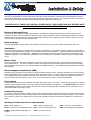
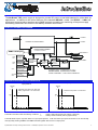
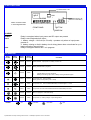
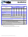
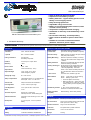
Phone: +64 9 835 0700
Fax:
+64 9 837 3446
NZ Freephone: 0800 654 668
AU Freephone: 1800 148 494
Email: [email protected]
www.innovative.co.nz
User Manual
SR100i….LAN+
No-BreakTM DC UPS with SNMP communications port
100W
Please refer to separate user manual for full SNMP instructions
Specifications are subject to change without notice. No liability accepted for errors or omissions.
1
Safety
The user is responsible for ensuring that input and output wiring segregation complies with local standards and that in
the use of the equipment, access is confined to operators and service personnel. A low resistance earth connection is
essential to ensure safety and additionally, satisfactory EMI suppression (see below).
HAZARDOUS VOLTAGES EXIST WITHIN A POWER SUPPLY ENCLOSURE AND ANY REPAIRS MUST
BE CARRIED OUT BY A QUALIFIED SERVICEPERSON.
Electrical Strength Tests
Components within the power supply responsible for providing the safety barrier between input and output are constructed to provide electrical isolation as required by the relevant standard. However EMI filtering components could be
damaged as result of excessively long high voltage tests between input, output and ground. Please contact our technicians for advice regarding electric strength tests.
Earth Leakage
The EMI suppression circuits causes earth leakage currents which may be to the maximum allowable of 3.5mA.
Ventilation
High operating temperature is a major cause of power supply failures, for example it has been well documented that a
10oC rise in the operating temperature of a component will halve its expected life. Therefore always ensure that there is
adequate ventilation for the equipment. Batteries and cooling fans also suffer shortened lifetimes if subjected to high
ambient temperatures - both should be included in a routine maintenance schedule to check for signs of reduced efficiency.
Water / Dust
Every effort must be made in the installation to minimise the risk of ingress of water or dust. Water will almost always
cause instant failure. The effects of dust are slower in causing failure of electronic equipment but all electrical equipment should be cleaned free of any dust accumulation at regular intervals. This is particularly important where internal
fans are fitted.
Electromagnetic Interference (EMI)
Switching power supplies and converters inherently generate electrical noise. All wiring should be as short as practicable and segregated from all equipment wiring which is sensitive to EMI. Residual noise can be reduced by looping DC
wiring through ferrite cable sleeves. These are most effective as close to the power supply as possible and as many
turns of the wire taken through the core (+ and - in the same direction) as the core will accommodate.
Fuse ratings
Check that the wiring and fuses or MCBs match the rating of the PSU or converter. Adequate fuse protection of battery
circuits is very important owing to the large potential currents available from batteries. Our No-Break DC series has an
internal ECB for protection of the battery circuit but for all other charging situations should have an external fuse or circuit breaker fitted in the battery circuit.
Connection polarity
It is critical to check the polarity carefully when connecting batteries and equipment to DC power supplies and chargers.
Boost chargers (and some float chargers) made by Innovative Energies have reverse polarity protection, which can be
by an electronic switch (non-destructive) or an internal fuse which needs to be replaced if a battery is connected in reverse.
Glossary of terms used in our user manuals
PSU = power supply unit
BCT = battery condition test
ELVD = electronic low voltage disconnect RPP = reverse polarity protection
SNMP = Simple Network Management
Protocol
ECB = electronic circuit breaker
EMI = electromagnetic interference
LAN = local area network
Specifications are subject to change without notice. No liability accepted for errors or omissions.
2
The No-Break ™DC power supply is designed to provide DC power to lead acid batteries for critical back up
applications. In addition to the normal features of the standard SR100C.. model, the SR100i….-LAN+ has
an ethernet communication interface using SNMP protocol to enable user monitoring of the power supply
and battery parameters and control of the battery condition test function.
No-Break™ SYSTEM BLOCK DIAGRAM
I LOAD
AC MAINS
LOAD +
POWER CONVERSION
OUTPUT VOLTAGE, CURRENT
LIMIT & BATTERY CHARGE
CURRENT CONTROL
STANDBY
SNMPLED
comms
LED port
&
OFF
LOAD -
I CHARGE
BATTERY +
BUTTON
BATTERY TEMP.
SENSOR
POWER
OK LED
LED
ON
BATTERY
MANAGEMENT
& ALARM
CIRCUIT
BATTERY
SYSTEM
OK LED
LED
ON
ALARM
OFF
MAINS FAIL /
POWER SUPPLY
FAIL ALARM
ALARM
OFF
BATTERY
SYSTEM
FAIL ALARM
BATTERY BATTERY
CURRENT
SENSE
ELECTRONIC
CIRCUIT
BREAKER
REVERSE
POLARITY
FUSE
NORMAL OPERATION
LOAD CURRENT < PSU MAX CURRENT
OPERATION OF ELECTRONIC CIRCUIT BREAKER (ECB)
Input power off
Input power on
Trip time
ms
Trip time
ms
ECB does not trip below 2.5x I PSU rated
Battery supplies max of 1.5 x IPSU rated
ECB does not trip below 1.5x I PSU rated
300
300
2
2
2.5
6
System load current
(x I PSU rated)
The ECB is activated under the following conditions: 1.
2.
1.5
5
System load current
(x I PSU rated)
battery voltage drops below the Vdisco (1.66V/cell)
battery current overload (refer to graphs above)
The ECB will latch open only when there is no input power present. It will reset when input power is restored or can be manually
reset by briefly shorting the BAT- and LOAD- terminals together when there is no input power.
Specifications are subject to change without notice. No liability accepted for errors or omissions.
3
CONNECTION DIAGRAM
L+, B+ are linked internally and labelled COM
SR... i......-LAN+
L+
AC input
~
L-
=
B+
B-
ALARMS
LOAD
ethernet
comms
port
for
SNMP
BATTERY
Temperature sensor to be
placed on or near battery
CONNECTION & INITIAL TESTING
1
2
3
4
5
6
7
8
9
10
Check input and output voltages of system, ensure that they match the equipment. All loads should be
isolated.
Check polarity of all wiring. Place temperature sensor probe near or on batteries.
Plug in input power. “POWER OK” and “BATT OK” LEDs will light up. “BATT OK” will go out in about
10 secs as there is no battery connected. DC output voltage should appear at both load and battery
outputs.
Turn off input power.
Connect battery.
Check that ECB (internal electronic circuit breaker) closes by shorting together the BATTERY –ve and
LOAD –ve terminals briefly. Both LEDs will light up. If this does not happen, there is a fault in the
wiring or the internal battery protection fuse is ruptured (see Note 2 below). The battery voltage will
then appear at the load terminals and the “BAT LOW” alarm relay energises. The “POWER OK” LED
stays on for about 30 seconds and then goes out
Connect load wiring to LOAD+ and LOAD- terminals.
Turn on input power for the system to be operational.
Please refer to separate user manual for setting up the SNMP web interface.
Connect network cable to monitor power supply parameters (refer to separate instructions for SNMP
setup)
NOTES
1
2
3
4
Maximum current available
with input power present:
2.5 x rated PSU current
with no input power:
1.5 x rated PSU current
Reverse polarity protection
If the battery is connected in reverse, the internal battery protection fuse may be ruptured and the unit
should be returned to the manufacturer for repair. If the fuse is good, the voltage measured as at
step 3 above should be exactly the same on both the load and battery outputs.
Battery Condition Test (BCT)
BCT function is disabled on start up and is controlled via the SNMP interface.
BCT fail reset
If the system fails a BCT the BAT LOW alarm latches (de-energized state) until
either: both the mains power input and the battery are disconnected briefly
or:
the system passes the next BCT.
Specifications are subject to change without notice. No liability accepted for errors or omissions.
4
ALARM CONNECTIONS
To network router or PC
INPUT
LAN
ALARMS
DC OUT
+ - + -
NC NO C NC NO C NC NO C
AUX
Alarm contacts shown
in de-energized state.
POWER
BATT
Temperature sensor to be
placed on or near battery
LOAD BATT
BATT OK
FRONT PANEL
POWER OK
ALARMS
POWER:
Relay is energized when input power and DC output are present
BATT:
Relay is de-energized when either:
1. battery voltage = 1.8V/cell (for 2V cells) - operates only when no input power
present or
2. battery missing or fault in battery circuit wiring (alarm does not activate for up to
battery detection interval time).
Relay is energized when a BCT is in progress.
AUX:
LED INDICATION
Power
OK LED
Battery
OK LED
Power
Alarm
Battery
Low Alarm
Normal
Normal
System Normal: Input power on, battery circuit is OK
Normal
Normal
Battery detection test in progress
Normal
Alarm
Alarm
Normal
Alarm
Alarm
Input power off or PSU has failed and battery has discharged to < V batl
Alarm
Alarm
Input power off, ELVD has activated and disconnected battery from load
Normal
Normal
Normal
Alarm
Condition
Input power on, battery system fault:
LEGEND :
=On
1.
2.
Internal battery fuse has opened or
Battery circuit wiring open circuit, battery missing, ECB has tripped
Input power off or PSU has failed.
Battery system is OK (battery volts > Vbatl)
BCT is in progress: LEDs flash slowly
Input power on, battery voltage < Vpres during a BCT
= fast flash
= slow flash
Specifications are subject to change without notice. No liability accepted for errors or omissions.
=Off
5
Default Settings (at 20°C)
Nominal Voltage
Parameter
Default
Value
12V
24V
30V
36V
48V
*1 V out = Output voltage
13.8
27.6
34.5
41.4
55.2
2.3V/cell
V pres = Voltage threshold for battery detection & battery condition test (BCT). If voltage
drops to this level during BCT then the test is
aborted and BATT SYS OK relay de-energises
12.2
24.4
30.5
36.6
48.8
2.03V/cell
11.5
23
28.8
34.5
46
1.92V/cell
11
22
27.6
33
44
1.84V/cell
10
20
25
30
40
1.66V/cell
V shutd = Output voltage of PSU during battery detection & BCT
V batl = Battery low alarm voltage during
mains fail.
(BATT SYS OK alarm relay de-energizes)
V disco = Battery disconnect voltage during
mains fail
Bccl = Maximum charge current as % of rated PSU rated current
*2
Comms = communications mode of PSU: F = continuous data stream of status
M = responds only to request made by a controller
M
BatDetect = Battery detection interval time, active only when no battery charge current is detected (the
unit may not detect a missing battery for up to this time)
60 min
BCT = length of battery condition test
20 min
Ret = retest option: N = after a failed BCT further scheduled BCTs are inhibited
Y = after a failed BCT further scheduled BCTs will be allowed
Y
CC = Length of charge cycle in minutes/hours/days. ie. time between battery condition tests
40m/23h/
027d
MfiBCT = time before mains fail check during BCT. A mains fail during a BCT will stop the BCT. If set
longer than BCT time no mains fail check will occur.
30 min
NOTES:
*1
Output voltage is set by an internal potentiometer.
*2
Refer to model table or label at the front of this manual if non-standard
Specifications are subject to change without notice. No liability accepted for errors or omissions.
6
Notes
Specifications are subject to change without notice. No liability accepted for errors or omissions.
7
With communication port
Serial or Ethernet options available
Separate load and battery outputs
Battery detection - regular battery presence and
SR100 i with ethernet communication port
♦ 24 Month Warranty
battery circuit integrity checks
Deep discharge protection
Adjustable charge current limit
Battery circuit protected against overload, short
circuit & reverse polarity
Temperature compensated float charging
Automated or manually controlled battery condition test
No transition switching to backup battery
Alarm contacts & LEDs for precise fault indication
Suitable for use with all lead acid batteries
(batteries external to power supply)
SPECIFICATIONS All specifications are typical at nominal input, full load and at 20°C unless otherwise stated.
ELECTRICAL
No-Break™ FUNCTIONS AND ALARMS
Input Voltages
▪ standard
180V - 264VAC 45-65Hz
Battery Charge
Current Limit
See Model Table for default settings.
(25% & 50% settings available on request)
▪ optional
88V - 132VAC 45-65Hz
Reverse Polarity
Battery reverse connection will open internal
fuse (and produce alarm)
Fusing / Protection
AC input fuse
DC battery output fuse
Battery Monitoring
Isolation
1KV DC input - output / earth
Detects for presence of battery on start up,
then every 60 minutes when charge current
< 200mA
Battery Protection
Efficiency
> 85%
Inrush current
<30A, 1.8ms
Electronic Circuit Breaker (ELCB) operates
under the following conditions:
ELVD (electronic low voltage disconnect)
activates when battery voltage drops to
1.67V/cell (adjustable) - auto reset
Output Power
100W continuous (0 - 50°C)
Output Voltages
13.8V, 27.6V, 41.4V, 55.2V
Other voltages by request.
- battery discharged
- overload
- short circuit
Allows ~150% load from battery without acting, operates within 300ms for total load >
600%
Acts within 2ms, backed up by fuse
Voltage adj. range
85 - 105% of Vout
LED Indication
Temp. Compensation
Temperature sensor on 1.7m lead with adhesive pad: -4mV / °C / cell ±10%
Green:
Green:
Alarms
•
•
Input power on & PSU working
Battery system intact
Power OK (Mains or PSU fail)
Battery System OK - alarms when battery voltage low (on mains fail) , battery
missing, battery circuit wiring faulty, BCT
fail
Current Limit
Output current limit set at rated FLC
Line Regulation
<0.04% over AC input range
Load Regulation
<0.5% open circuit to 100% load
Noise
<0.3%
Transient response
200mV over / undershoot,
load step 20-100%, 400us settling time
Thermal Protection
Automatic current de-rating if >50°C. Selfresetting.
PHYSICAL
AC Input connector
IEC320 input socket (similar to PCs etc.)
Hold-up time
15 - 20 ms (nom. - max. Vin) without
battery
DC Connections
Plug-in style socket & mating screw terminal
block: (max. wire 2.5mm² / way)
Alarm Connections
Plug in screw terminal block
Alarm Relay contacts C - NO - NC full changeover rated
30VDC,2A /110VDC,0.3A/125VAC,0.5A
Battery Condition
Test (BCT)
Default setting: 20mins every 28days
Enclosure
Zinc plated steel / powder coated lid
EMI
to CISPR 22 / EN55022 class A
Dimensions
147W x 177D x 62H mm
Safety
to IEC950 / EN60950 / AS/NZS3260
Weight
0.95 Kg
STANDARDS
Specifications are subject to change without notice. No liability accepted for errors or omissions.
8
100 Watt
No-Break™ DC UPS
STANDARD PREFERRED MODEL TABLE
DC Output
MODELS
Output Voltage
(Load & Charger)
Max. Recomm.*1
Load Current
(I LOAD)
Charge
Current limit*2
(I CHARGE)
PSU Rated
Current (I PSU )
SR100i 12
13.8V
6.0A
7.5A
7.5A
SR100i 24
27.6V
3.0A
3.7A
3.7A
SR100i 36
41.4V
1.9A
2.4A
2.4A
SR100i 48
55.2V
1.5A
1.9A
1.9A
ENVIRONMENTAL
*1
to allow for adequate
charging current
*2
25% & 50% settings
available on request
OPTIONS
Operating
temperature
0 - 50 °C ambient at full load
De-rate linearly >50 °C to no load @ 70 °C
Communication Port
for -i & V versions
Choice of RS485, RS232, Ethernet
Storage temperature
-10 to 85 °C ambient
+PROTOCONMB-x
Humidity
0 - 95% relative humidity non-condensing
Protocol Converter (RS485 to MODBUS) with
programming port for PC. Power MBLink
setup software supplied -x = blank
x = -OE for above plus Ethernet Port
Parallel Redundancy
Use external output diode: eg. +P15 or any
suitably rated diode bridge rectifier.
ACCESSORIES SUPPLIED
Mounting Feet together with screws
AC power cord Standard 1.5m lead with IEC320 socket / local plug
DC connector with mating screw-terminal plug
Alarm connector with mating screw-terminal plug
CABINET OPTIONS
19”Rack Mount
2U sub rack option: add SR-RM2U
Optional V/I meter for subrack: SR-METER
Wall Mount Enclosure PSU may be fitted into enclosure with MCBs
and terminals. Code: SEC-SR
SR100i with RS485 comms port
MODEL CODING AND SELECTION CHART
SR100i12 T X G-LAN+
Communications Interface
Port
485 = RS485
232 = RS232
LAN+ = Ethernet (SNMP)
230V AC
110V AC
= blank
=G
Temperature Compensation:
Yes = T
No = blank
DC output: Nominal battery voltage:
12, 24, 30, 36, 48
Function:
C = No-Break™
Input voltage
LAN = ethernet (ASCII code)
Blank = no comm. port
Plug-in /screw terminal connector
Specifications are subject to change without notice. No liability accepted for errors or omissions.
i = No-Break™ with comms interface
9
No-Break DC & standard N+1 connections
#1 1 x No-Break™DC charger and 1 x battery bank
#2 1 x No-Break™DC charger and 2 x battery banks
This is the basic connection which is most commonly used, and provides
adequate protection for the majority of systems requiring DC back up in
the event of a mains power failure.
The SR250xxxV No-Break™DC UPS is designed to provide superior
battery backup availability without having to use two power supplies.
Dual battery banks and automatic battery condition testing reduce the risk
of battery failure for critical applications.
SRxxxC
SRxxxV
L+
L+
LOAD
L-
B+
INPUT
INPUT
B1+
ECB
B2+
=
B-
=
ECB
BAT 1
B1-
LOAD
B2-
BAT 2
RES
L-
RES
ALARMS
BCT LOAD
ALARMS
COMMS PORT
Alarms Available
Single battery DC
backup system
Alarms Available
Power OK
YES
Battery Missing
YES
Battery Low
YES
Battery Condition Test Fail
YES
N+1 redundancy for
batteries
Power OK
YES
Battery Missing (B1&B2)
YES
Battery Low (B1&B2)
YES
Battery Condition Test Fail
(B1 & B2)
YES
#3 2 x No-Break™DC chargers and 2 x battery banks
#4 No-Break™DC Connection for high peak loads
2 x No-Break™DC chargers connected in parallel with separate battery
banks & output diodes. This solution provides an extremely high level
of redundancy for very critical applications, with redundancy of the
battery in addition to the power supply. The diodes isolate the units
from one another in the event of a short circuit appearing at the other
output and aid current sharing.
This is a basic connection which is used when there is a connected load
with a peak current greater than 1.5 times the rated current of the
charger. Standing loads are connected normally and an optional external low voltage disconnect may be used for the peak load.
SRxxxC
SRxxxC
L+,B+
INPUT
B-
L+,B+
INPUT
BAT
BAT
ECB
=
L-
NORMAL
LOAD
B*LVD
=
ALARMS
ECB
LOAD
LALARMS
SRxxxC
* optional
L+,B+
INPUT
PEAK
LOAD
BECB
L-
=
ALARMS
Alarms Available
N+1 redundancy for
charger and batteries
Alarms Available
YES
Power OK
YES
Battery Missing
YES
Battery Low
*1 interlock circuit required for
automated BCT
Battery Condition Test Fail*
1
Single battery DC
backup system for
peak loads
YES
Specifications are subject to change without notice. No liability accepted for errors or omissions.
Power OK
YES
Battery Missing
YES
Battery Low
YES
Battery Condition Test Fail
YES
10
No-Break DC connections (continued)
#5 N+1 for No-Break™DC charger and single battery
bank
#6 N+1 for No-Break™DC charger and N+1 for battery
bank (use this connection for high peak loads)
This connection provides for redundancy of the charger and retains most
of the No-Break functions.
All No-Break alarms are available and the low voltage disconnect for the
peak load is optionally implemented with an external relay.
SRxxxC
B+,L+
SRxxxC
BAT
INPUT
=
BECB
BAT
INPUT
LOAD
=
L-
SRxxxC
B+,L+
L-
B+,L+
INPUT
INPUT
=
BAT
=
BECB
NORMAL
LOADS
*1
BECB
PEAK
LOAD
ALARMS
ALARMS
SRxxxC
B+,L+
*1
BECB
L-
LALARMS
*1 OPTIONAL LVD
ALARMS
Alarms available
*1 interlock circuit required for
automated BCT
Alarms available
Power OK
YES
Battery missing
NO
YES
Battery low
1
Battery condition test fail*
*2 interlock circuit required for
automated BCT
Power OK
YES
Battery missing
YES
YES
Battery low
2
YES
Battery condition test fail *
YES
Standard N+1 redundant DC connections
#7 Standard AC/DC power supplies with alarms and
external diodes
#8 Standard AC/DC power supplies with internally fitted diodes (applies only to SR100P and SR250P models with outputs >12VDC)
+
SRxxxD
+
SRxxxP
INPUT
INPUT
LOAD
LOAD
=
-
ALARMS
=
ALARMS
+
SRxxxD
+
SRxxxP
INPUT
-
=
ALARMS
Specifications are subject to change without notice. No liability accepted for errors or omissions.
=
INPUT
ALARMS
11
TERMS OF WARRANTY
Innovative Energies Ltd warrants its power supplies for
24 months (two years) from date of shipment against
material and workmanship defects.
Innovative Energies' liability under this warranty is limited to the replacement or repair of the defective product
as long as the product has not been damaged through
misapplication, negligence, or unauthorized modification
or repair.
Thank you for purchasing from
Innovative Energies.
We trust your power supply will exceed
your expectations and perform for years
to follow.
Sincerely,
The Innovative Energies team.
Innovative Energies Limited
Phone:
Freephone:
+64 9 835 0700
0800 654 668 (New Zealand)
1800 148 494 (Australia)
Fax:
+64 9 837 3446
Email:
[email protected]
Online:
www.innovative.co.nz or www.innovative-energies.com
In Person:
1 Heremai Street, Henderson, Auckland, New Zealand
By Post:
PO Box 19-501, Auckland 1746, New Zealand
20/10/11