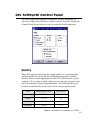
1
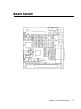
PCM-3200
PC/104 Sound Module
Copyright Notice
This document is copyrighted, 1997. All rights are reserved. The
original manufacturer reserves the right to make improvements to
the products described in this manual at any time without notice.
No part of this manual may be reproduced, copied, translated or
transmitted in any form or by any means without the prior written
permission of the original manufacturer. Information provided in
this manual is intended to be accurate and reliable. However, the
original manufacturer assumes no responsibility for its use, nor
for any infringements upon the rights of third parties which may
result from its use.
Acknowledgements
YAMAHA and OPL are trademarks of YAMAHA Corporation.
Sound Blaster Pro, Sound Blaster 16 and Wave Blaster are registered
trademarks of Creative Technology Ltd..
PC/104 and the PC/104 logo are registered trademarks of the PC/
104 Consortium.
Microsoft, MS-DOS, and MS are registered trademarks of Microsoft
Corporation.
Windows, Windows 95, and Windows NT are registered trademarks
of Microsoft Corporation.
IBM, AT, OS/2 and Micro Channel are registered trademarks of
International Business Machines Corporation.
All other product names or trademarks are properties of their
respective owners.
2007320001 Manual PCM-3200 Rev.A1 2nd Ed.
Printed in Taiwan December 1997
Packing Set
Before you begin installing PCM-3200 card, please make sure that
the following materials have been shipped:
- 1 PCM-3200 PC/104 Sound Module
- 1 PCM-3200 User’s Manual (this document)
- 3 Driver disks for DOS, Windows 3.1, Windows 95, Windows NT
4.0, and YAMAHA Audio Rack Software application utilities
- 2 Audio Adapter Cables
If any of these items is missing or damaged, contact your distributor
or sales representative immediately.
Contents
Chapter 1 General Information ..........................1
Product Highlights ................................................................ 2
Introduction ............................................................................ 2
Features ................................................................................... 3
Specifications .......................................................................... 4
Technical Specifications ............................................................ 4
Physical and Environmental Specifications ............................... 4
Board layout ........................................................................... 5
Chapter 2 Hardware Installation ........................7
Jumpers, connectors and switches ........................................ 8
Locating jumpers .................................................................. 10
Locating connectors .............................................................. 11
Locating switches .................................................................. 12
Setting jumpers ..................................................................... 13
Safety precautions ................................................................ 14
Installing PCM-3200 Module .............................................. 14
Jumper configuration reference ............................................... 14
External Devices connecting ................................................ 15
Wave Blaster/MIDI Extension Connector (CN1) .................... 15
Modem Interface Connector (CN2) ........................................ 15
Game/Joystick/MIDI Connector (CN3) .................................. 15
Mono Input Connector (CN4) ............................................... 15
Panasonic CD Audio Input Connector (CN5) ......................... 15
Mitsumi CD Audio Input Connector (CN6) ............................ 15
Stereo Line In Connector (CN7) ............................................ 16
Stereo Line Out Connector (CN8) .......................................... 16
Speaker Out Connector (CN9) ............................................... 16
MIC Connector (CN10) .......................................................... 16
Chapter 3 Installation for Windows 95 .............17
Introduction .......................................................................... 18
Installing the Driver ............................................................. 18
OPL SoftSynth Control Panel ............................................. 23
Quality .................................................................................... 23
Reverb ................................................................................... 24
Filter ...................................................................................... 24
MPU401 OUT........................................................................ 24
Full Duplex ............................................................................. 24
Chapter 4 Installation for Windows 3.1 & DOS .25
Introduction .......................................................................... 26
Installing the Driver ............................................................. 26
SETUPSA2 ............................................................................ 30
OPL SoftSynth Control Panel ............................................. 31
Quality .................................................................................... 31
Reverb .................................................................................... 32
Filter ....................................................................................... 32
MPU401 OUT........................................................................ 32
Full Duplex ............................................................................. 32
Chapter 5 YAMAHA Audio Rack Software .......33
Introduction .......................................................................... 34
System Requirements ........................................................... 38
How to Play ........................................................................... 38
Titling CDs .............................................................................. 39
Playlist .................................................................................... 40
Config ..................................................................................... 42
Error Messages ...................................................................... 44
Appendix A Installing PC/104 Modules .............45
Appendix B Pin Assignments ...........................49
PC/104 connectors .................................................................
Wave Blaster/MIDI Extension Connector (CN1) ....................
Modem Interface Connector (CN2) ........................................
Game/Joystick/MIDI Connector (CN3) .................................
Panasonic CD Audio Input Connector (CN5) .........................
Mitsumi CD Audio Input Connector (CN6) ............................
50
51
51
52
52
52
CHAPTER
General
Information
1
This chapter gives background information on the PCM-3200.
(YAMAHA OPL3-SAx & OPL4-ML
Sound System).
You can find out :
l
Product Highlights
l
Product Features
l
Compatibility
l
Product Specifications
l
Card Layout
Chapter 1 General Information
1
Product Highlights
l
PC/104 Embedded-PC Module.
l
Sound Blaster Pro & 16 compatible.
l
Built-in YAMAHA OPL3 FM synthesizer.
l
Built-in YAMAHA OPL4 Wavetable synthesizer.
l
Built-in General MIDI interface.
l
ISA Plug and Play (PnP).
l
Full duplex for concurrent recording and playback.
l
Proven YAMAHA compatibility, quality and reliability.
Introduction
The PCM-3200 sound card offers a wide range of flexible, economical and expandable solutions that can satisfy diverse needs in audio
applications.
The kernel of PCM-3200 is the YAMAHA OPL chips that are the
industry standard music synthesizers found in most personal computer audio boards. The OPL3 uses FM synthesis techniques which are
proprietary to YAMAHA. The OPL3-SA single chip audio solution
integrates audio CODEC, DOS games compatibility and D/A converter with FM synthesis in one package. The OPL3-SA replaces up to
four devices used in current Soundblaster compatible audio subsystems.
For the high end of sound quality, the OPL4 family in the PCM-3200
combines synthesis techniques to produce rich musical sound using
YAMAHA's unique FM-enhanced wavetable synthesis. The OPL4-ML
chip combines the FM/wavetable synthesizer with a wavetable sample
ROM and General MIDI interface into one package. The PCM-3200
uses the first truly cost-effective implementation of wavetable
synthesis in your applications.
Whatever the particular configuration, each of the PCM-3200 audio
system can be relied on the high levels of quality, compatibility and
reliability.
2
PCM-3200 User's Manual
Features
l
YAMAHA’s Sproven YMF718 (OPL3-SA2C) and YMF704B
(OPL4-ML) chip.
l
Contains 8-Mbit Wave table ROM.
l
Supports industry standard PC Game compatibility.
l
Supports Windows Sound System compatibility.
l
Supports Plug and Play ISA 1.0a compatibility.
l
Built-in 16-bit Sigma-Delta stereo CODEC.
l
Programmable Sample Rate from 5.5kHz to 48kHz for Recording/
Playback.
l
Hardware and software master volume control.
l
Dual DMA (supports DMA Demand Mode) with FIFO for full duplex.
l
Supports IMA ADPCM, A-Law, µ-Law, Compression / Decompression.
l
MPU-401 compatible MIDI interface.
l
Built-in 6-channel stereo mixer (Line, Aux1, Synth(Aux2), SB, CODEC,
MIC).
l
Supports 5-channel analog input (Line, Aux1(CD), Aux2(External Synthesizer), MIC, MIN).
l
Wave table synthesis is able to generate up to 24 voices simultaneously.
l
Complies with GM system Level 1.
l
24mA TTL bus driver capability.
l
5V, 12V, -12V power supply for digital and analog.
l
Supports power management.
Chapter 1 General Information
3
Specifications
Technical Specifications
Computer BUS : PC/104 (ISA) Standard
Bus Width : 16-bit
Input/Output Connectors :
Wave Blaster
l Game/MIDI Port
l Line Out
l Line In
l Microphone In
l Mitsumi CD-ROM Audio
l Panasonic CD-ROM Audio
l Monaural In
Compatibility
l
l
l
l
l
l
l
Input/Output
Input/Output
Output
Input
Input
Input
Input
Input
Adlib
Sound Blaster Pro applications
Sound Blaster 16 applications
YAMAHA OPL3 FM Synthesizer
YAMAHA OPL4 Wavetable Synthesizer
MPU-401 UART MIDI
Physical and Environmental Specifications
Length : 3.6 inches
Width : 3.8 inches
Operating Temperature : 32 to 140 °F (0 to 60 °C)
Humidity (operating) : 5% to 95% Non-Condensing
Power Requirements : 5V, 12V, -12V
4
PCM-3200 User's Manual
Board layout
Chapter 1 General Information
5
6
PCM-3200 User's Manual
CHAPTER
Hardware
Installation
2
This chapter tells you how to set up the
PCM-3200 (YAMAHA OPL3-SAx &
OPL4-ML Sound System) hardware,
including instructions on setting jumpers
and connecting external devices.
Be sure to read all the safety precautions
before you begin the installation procedures.
Chapter 2 Hardware Installation 7
Jumpers , Connectors and Switches
Connectors on the board link it to external audio devices and other
PC/104 modules. In addition, the board has a number of jumpers that
allow you to configure the audio application to suit your systems.
The table below lists the function of each jumpers and connectors:
Jumpers
Label
Function
JP1
Select OPL4-ML analog output or wave blaster
connector enable
Connectors
Label
Function
J1
PC/104 ISA-bus expansion
J2
PC/104 ISA-bus expansion
CN1
Wave Blaster/MIDI Extension connector
CN2
Modem Interface connector
CN3
Game/Joystick/MIDI connector
CN4
Mono Input connector
CN5
Panasonic CD Audio Input connector
CN6
Mitsumi CD Audio Input connector
CN7
Stereo Line In connector
CN8
Stereo Line Out connector
CN9
Speaker Out connector
CN10
MIC connector
CN11
Volume control-Up header
CN12
Volume control-Down header
Switches
Label
Function
SW1
Volume Control - UP (1.5dB increase/push)
SW2
Volume Control - Down (1.5dB decrease/push)
Notes : Pushing the two switches at the same time performs the
mute
function.
8
PCM-3200 User's Manual
Locating Jumpers, connectors and
switchhes
CN11
CN1
CN6
CN5 CN12
SW1
SW2
CN8
CN4
CN7
JP1
CN9
CN10
CN2
CN3
J2
J1
Chapter 2 Hardware Installation 9
Setting Jumpers
To match the needs of your application, you need to configure your
PCM-3200 by setting jumpers. A jumper is the simplest kind of
electric switch. It consists of two metal pins and a small metal clip
(often protected by a plastic cover) that slides over the pins to
connect them. To ”close” a jumper you connect the pins with the clip.
To ”open” a jumper you remove the clip. Sometimes a jumper will
have three pins, labeled 1, 2, and 3. In this case you would connect
either pins 1 and 2 or 2 and 3.
1
Open
Closed
2
3
Closed 2-3
The jumper settings are schematically depicted as follows:
123
Open
Closed
Closed 2-3
A pair of needle-nose pliers may be helpful when working with
jumpers.
If you have any doubts about the best hardware configuration for
your system application, contact your local distributor or sales
representative before you make any changes.
10
PCM-3200 User's Manual
Safety Precautions
Warning ! Always completely disconnect the power cord from your
chassis whenever you are working on it. Do not make connections while the power is on because sensitive electronic
components can be damaged by the sudden rush of power.
Only experienced electricians personnel should open the PC
chassis.
Caution ! Always ground yourself to remove any static charge before
touching the card. Modern electronic devices are very
sensitive to static electric charges. Use a grounding wrist strap
at all times. Place all electronic components on a staticdissipative surface or in a static-shielded bag when they are
not in the chassis.
Installing PCM-3200 Module
Factory Default Settings
PCM-3200 Sound Module default configuration that supports the
Plug and Play 1.0a specification will depend on the available system
resources.
Jumper Configuration Reference
Only one jumper block on the PCM-3200 Sound Module is used to
configure user-selectable wave table options.
Jumper Block JP1:
This pin pair is used to set AUX2 line.
JP1 1-4 & 2-3 Both Close = OPL4-ML analog output L,R
line enable (*)
JP1 1-4 & 2-3 Both Open = Wave Blaster connector
enable
(* means
default setting)
Chapter 2 Hardware Installation 11
External Devices Connecting
Wave Blaster/MIDI Extension Connector (CN1)
The wave table connector is used to attach an external wave table card
for playback, mixing, or recording.
Modem Interface Connector (CN2)
This connector provides chip select signal (/MCS) and IRQ input
(MIRQ) pins to control external devices such as a modem. These pins
should be No-connects if not used.
Game/Joystick/MIDI Connector (CN3)
The Game/MIDI Port connector (15-pin D-sub) is used to attach a
joystick for game interface or to attach an external FM synthesizer
for playback, mixing, or recording.
Mono Input Connector (CN4)
Mono input connector is provided that allows routing of the PC
speaker to the PCM-3200 sound card. This allows the PC-speaker to
be the output of the PCM-3200.
Panasonic CD Audio Input Connector (CN5)
The Panasonic CD audio input connector is used to connect the audio
cable from Panasonic CD-ROM drive for playback, mixing, and
recording.
Mitsumi CD Audio Input Connector (CN6)
The Mitsumi CD audio input connector is used to connect the audio
cable from Mitsumi CD-ROM drive for playback, mixing, and
12
PCM-3200 User's Manual
recording.
Stereo Line In Connector (CN7)
The Stereo Line In phone-jack is used to attach stereo devices such
as cassette, digital audio tape, or minidisk players for playback,
mixing, or recording.
Stereo Line Out Connector (CN8)
The Stereo Line Out phone-jack provides the non-amplified output
for the stereo channels (left and right). The output is for attaching
powered speakers or an external audio amplifier. When used in
conjunction with the Speaker Out output, the surround sound function
will be activated.
Speaker Out Connector (CN9)
The Speaker Out phone-jack provides the built-in power amplifier
outputs for the left and right stereo channels. When used in conjunction with Line Out output, the surround sound function will be
activated.
MIC Connector (CN10)
The Microphone In phone-jack is used to attach a microphone for
live audio input for playback, mixing, or recording. A 20dB gain can
be obtained internally. The microphone input impedance will be
around 1.8k ohm.
Volume Control-Up header (CN11)
This pin header can be connected to an external Volume Control-Up
switch.
Volume Control-Down header (CN12)
This pin header can be connected to an external Volume ControlDown switch.
Chapter 2 Hardware Installation 13
14
PCM-3200 User's Manual
CHAPTER
3
Installation for
Windows 95
Use this chapter to install PCM-3200
drivers for Windows 95:
l
l
Installation procedures
Use OPL SoftSynth to setup GM
configuration
Chapter 3 General Information
15
Introduction
The PCM-3200 (YAMAHA OPL3-SAx Sound System) driver is stored
in three floppy disks.
Please install Windows 95 driver when use on Windows 95.
Installing the Driver
The PCM-3200 supports Windows 95 Plug-and-Play. When you start
Windows 95, the automatic search option for the Add New Hardware
Wizard works as described below.
1. The following dialog box appears. Select “Driver from disk
provided by hardware manufacture” as shown below, then click
OK.
NOTE:
As the resouce data is that of OPL3-SA3, the dialog box represents as
OPL3-SA3. When OPL3-SA2 is mounted. It shows “OPL3-SA2” Sound
Board.
16
PCM-3200 User's Manual
The following dialog box appears.
Insert the Driver floppy disk into the disk drive and click OK, or
identify appropriate directory (WIN95) on the CD-ROM drive.
The drivers are going to be installed into your hard disk drive.
This is for the PCM-3200 (YAMAHA OPL3-SAx Sound System)
installation.
The game port joystick driver is detected and installed automatically.
Chapter 3 General Information
17
2. The following dialog box appears. Select “Do not install a driver”
as shown below, then click OK.
Note:
You can use PCM-3200 (YAMAHA OPL3-SAx Sound System) COM
port for modem interface. In this case, install Windows standard driver
or identify YAMAHA Windows 95 driver same as above 1.
18
PCM-3200 User's Manual
The following dialog box appears.
Select “Driver from disk provided by hardware manufacture” as shown
below, then click OK. (Keep the Driver floppy disk2 in the disk drive)
Note:
This is for standard IDE/ESDI Hard Disk Controller installation. If the
board does not support the controller, select “Do not install a driver”.
3. To make sure that the PCM-3200 (YAMAHA OPL3-SAX Sound
System) Driver has been installed correctly, open the System
Properties dialog box in the control panel.
Chapter 3 General Information
19
ex1. Sound System & Game port Joystick
If "YAMAHA OPL3-SAx Game Port" and "YAMAHA OPL3-SAx
Sound System" appear, the PCM-3200 installation is successfully
completed.
20
PCM-3200 User's Manual
OPL SoftSynth Control Panel
The Soft Synthesizer supports GM System Level 1 MIDI data. Its
volume is adjusted by the Wave volume control. The OPL SoftSynth
Control Panel shown below is used to setup the Soft Synthesizer.
Quality
These four options determine the sound quality (i.e., sampling rate)
and the number of voices that the SoftSynth can produce simultaneously. Select a mode appropriate for the CPU performance of your
computer. If you choose a high quality mode and your computer does
not have adequate processing performance, the SoftSynth may not
produce sound fluently. In this case, select a lower quality mode.
Chapter 3 General Information
21
M ode
Sam pling R ate (kH z)
M ax Voices
N orm al
11.025
16
G ood
22.025
16
Very G ood
22.025
24
Excellent
22.025
32
Reverb
If you choose ON, you can add reverb to the sound of the SoftSynth.
Filter
The SoftSynth sound is more fluent with the filter ON. This, however
with the filter ON, requires CPU resources.
MPU401 OUT
These settings allow you to select an External MIDI instrument or the
SoftSynth for use with DOS-based games that are played on Window
box. The MS-DOS Prompt item in the Main Program Group opens a
MS-DOS window. Select General MIDI in the game settings to use this
function.
Full Duplex
It is possible to record a new Wave file while playing an existing Wave
file.
Note:
SoftSynth/WaveOut of PCM-3200 (YAMAHA OPL3-SA2 Sound
System) is cooperative mode, you can play Wave data and SoftSynth
MIDI simultaneously.
22
PCM-3200 User's Manual
<MIC Volume Control>
When the “MIC +20dB” is checked, microphone volume increases
20dB during play back and recording.
<Tone Configuration>
This function can be controlled at using YMF715 (OPL3-SAX).
Tone Control
The quantity of bass and treble can be each adjusted by 2 pieces of
slider.
3D Enhanced
“Ymersion” is a Yamaha‘s original technology for wide stereo.
Default
When this button is clicked, the each value can be returned to default.
Chapter 3 General Information
23
Installing the Application (YSTATION)
and the Configuration Utility (SETUPSA)
If you in install
both the Audio Rack application “YSTATION” and the configuration
utility (SETUPSA) for DOS MODE of Win95, please refer to <case1>.
If you install
only the Audio Rack application “YSTATION”, please refer to
<case2>.
If you install
only the configuration utility (SETUPSA) for DOS MODE of Win95,
please refer to <case3>
Note:
“DOS MODE” means the status in which you select “shutdown”
Windows95 in the start menu and “Restart the computer in MS-DOS
mode”.
<case1> Installing the Application (YSTATION) and the Configuration Utility
(SETUPSA)
To install the Audio Rack “YSTATION” application and configuration
utility (SETUPSA) for DOS MODE of Win95:
1. Insert Disk [SA31INST] into your floppy disk drive or select
appropriate (APPLI) directory of CD-ROM.
2. Launch the MS-DOS prompt.
3. AT THE C:\DOS prompt, type
A:
24
PCM-3200 User's Manual
then press Enter.
If your floppy disk or CD-ROM drive is the B or E drive, type B: install
of A:, then press Enter. (For installation by CD-ROM, go to the
directory “APPLI:)
4. Type “WINSTALL -a”, and press Enter.
(Type “WINSTCD -a”, and press Enter. In the case of installation by
CD-ROM)
To use IDE CD-ROM interface of soundcard, add the option “-c” also
as follows. “WINSTALL -a -c”
(Type “WINSTCD -a -c”, and press Enter. In the case of installation
by CD-ROM)
5. Follow the on-screen instructions to complete the installation.
Note:
If you go to DOS-MODE from Win95, press “Start“ button, select
”Shut Down...“.
Then you can run the configuration utility (SETUPSA).
<case2> Installing the Application
To install the Audio Rack APPLICATION:
1. Insert Disk [SA31INST] into your floppy disk drive or select
appropriate (APPLI) directory of CD-ROM.
2. Launch the MS-DOS prompt.
3. At the C:\DOS prompt, type
A:
then press Enter.
If your floppy disk or CD-ROM drive is the B or E drive, type B: or E:
Chapter 3 General Information
25
instead of A:, then press Enter. (For installation by CD-ROM, go to the
directory “APPLI”)
4. Type “WINSTALL”, and press Enter.
(Type “WINSTCD -d”, and press Enter. In the case of installation by
CD-ROM)
5. Follow the on-screen instructions to complete the installation.
<case3> Installing the Configuration Utility
(SETUPSA)
To install the configuration utility (SETUPSA) for only DOS MODE of
Win95:
1. Insert Disk [SA31INST] into your floppy disk drive or select
appropriate (APPLI) directory of CD-ROM.
2. Launch the MS-DOS prompt.
3. At the C:\DOS prompt, type
A:
then press Enter.
If your floppy disk or CD-ROM drive is the B or E drive, type B: or E:
instead of A:, then press Enter. (For installation by CD-ROM, go to the
directory “APPLI”)
4. Type “WINSTALL -d”, and press Enter.
(Type “WINSTCD -d”, and press Enter. In the case of installation by
CD-ROM)
To use IDE CD-ROM interface of soundcard, add the option “-c” also
as follows. WINSTALL d c“
(Type “WINSTCD -d -c”, and press Enter. In the case of installation
by CD-ROM)
5. Follow the on -screen instructions to complete the installation.
26
PCM-3200 User's Manual
Note:
If you go to DOS-MODE from Win95, press “Start” button, select
“Shut Down...”, and select “Restart the computer in MS-DOS mode?”.
Then you can run the configuration utility (SETUPSA).
Using IDE CD-ROM interface in the DOS-MODE
In the DOS-MODE, when using IDE CD-ROM interface of soundcard,
Change the parameters of IDE in SETUPSA, because these are OFF as
default values. CD-ROM device driver should be bundled in
config.sys, and the CD-ROM driver is unique to each manufacture of
CD-ROM drive.
ex. : CD-ROM drive made by Mitsumi
In the “CONFIG.SYS” file, confirm or add the following two descriptions or rewrite:
DEVICE=C:\OPL3SA\SACDROM.SYS /P1E8 /I11 /A3EE
:
:
DEVICE=C:\MTM\MTMCDAI.SYS /D:MTMIDE01 /P:1F0,14 /P:1E8,11
In the “AUTOEXEC.BAT” file, confirm or add the following description or rewrite:
C:\DOS\MSCDEX.EXE /D:MTMIDE01 /S
:
If the CD-ROM drive cannot be recognized in your system, please
contact with the manufacture of CD-ROM drive.
Ymersion control supported by OPL3-SAx
Chapter 3 General Information
27
Ymersion, on-chip Yamaha 3D sound enhancement, can be controlled
by the Windows 95 standard volume control.
(1) Click “Options”, and select “Advanced Controls”.
28
PCM-3200 User's Manual
(2) Click left-bottom “Advanced” control button.
Note:
Do not check “2 ZV port Enable” while ZV port is not supported.
Chapter 3 General Information
29
30
PCM-3200 User's Manual
CHAPTER
4
Installation for
Windows 3.1 & DOS
Use this chapter to install PCM-3200
driver for Windows 3.1 and DOS:
l
l
Installation procedures
Use SoftSynth to setup GM
configuration
Chapter 4 Installation for Windows 3.1 & DOS
31
Introduction
The PCM-3200 (YAMAHA OPL3-SAx Sound System) driver and the
associated softwares are in two 2 HD floppy disks. The PCM-3200
requires MS-DOS 6.2 or Windows 3.1. The installation under other
operating systems is not garanteed to work properly. Installation from
MS-DOS leads to installation of windows 3.1 & DOS driver.
Along with the PCM-3200 driver, the following applications are
installed.
Typing optional command leads to set up DOS enviroment only. See
next page for details.
Installation
At first, make sure that CONFIGURATION MANAGER is installed in
your system before starting the installation of the Windows 3.1 &
DOS driver and even that of DOS only.
If Configuration Manager has not been installed, follow the guide
below to install Configuration Manager.
Install Plug and play Configuration manager
1. In DOS : (US mode: chev us[return])
2. Insert diskette [INSTALL (DISK1)] into drive A or B.
3. At the DOS prompt,
type A: instal [return] for diskette
4. Install as followed:
Insert the installation diskette [INSTALL (DISK2)] for
diskette installation
5. finish
6. reboot
7. auto configuration (by configuration manager)
Based on the resource information assigned by configuration manager,
Windows 3.1 & DOS driver of the PCM-3200 (YAMAHA OPL3-SAx
Sound System) can be installed.
32
PCM-3200 User's Manual
Install PCM-3200 (YAMAHA OPL3-SAx Sound System) Windows 3.1
& DOS driver.
An PCM-3200 must be in your system for successful driver installation.
This software is installed from the DOS prompt, not the Run command
in Windows.
The Installation program overwrites the existing AUTOEXEC.BAT and
Windows SYSTEM.INI files.
To cancel the Installation program, press the Esc key at anytime.
1. Insert Disk [SAINST] into your floppy disk drive.
2. At the C: DOS prompt, type
A:
then press Enter.
If your floppy disk drive is the B drive, type B: instead of A:
3. Type “Install” (for Windows) or “Install -d” (for only DOS),
and press Enter.
If Configuration manager, dwcfgmg.sys is not installed at Config.sys,
the following error message will be displayed. Install Windows 3.1 &
DOS driver after installing the Configuration manager.
Error : Configuration Manager was not installed.
4. Select and click YES.
If you’re not using a mouse, press the Return key for YES, or the Esc
key to Cancel.
Chapter 4 Installation for Windows 3.1 & DOS
33
The following dialog box appears.
5. Specify the installation directory for the OPL3-SAx Configuration
File or accept the default, then click OK.
The files are copied to the hard disk and the following dialog box
appears, informing you that parameter settings for the PCM-3200
(YAMAHA OPL3-SAx Sound System) have been added to the
AUTOEXEC.BAT file and a copy of the original AUTOEXEC.BAT file
has been saved as AUTOEXEC.BAK.
The following contents are written into the new AUTOEXEC.BAT.
After restart PC, these are valid.
- SET BLASTER (Setting the BLASTER function)
- SETUPSA2.EXE (that is written into the directory assigned at
“Configuration file will be installed to:”)
6. Click OK to continue.
note:
The installation of DOS only, the message that the installation is
completed is displayed. Then, click OK to finish the installation.
The following dialog box appears, asking whether or not you have
Windows installed on your computer.
34
PCM-3200 User's Manual
7. Click Yes if Windows 3.1 is installed on your computer. Click No
if it isn’t.
The following dialog box appears, asking whether or not you want to
install the OPL3-SAx (PCM-3200) Driver.
If you click Yes, the OPL3-SAx Driver for Windows is installed.
8. Click Yes to install. Click No not to install.
The following display appears.
9. Specify the installation directory for the Applications or accept the
default, then click OK.
The following dialog box appears, asking where Windows is installed.
10. Click OK if Windows is installed in the directory C:\Windows,
which is the default directory for Windows. Or specify a different
directory.
After the Windows settings have been changed, the following dialog
box appears, asking whether you want to replace the MIDI Mapper.
Chapter 4 Installation for Windows 3.1 & DOS
35
11. Select Yes to replace the current MIDI Mapper. Select No not to
replace it.
If a MIDI Mapper already exists and you replace it with the PCM-3200
(YAMAHA OPL3-SAx Sound System) MIDI Mapper, the original one
is saved as midimap.opl. See your Windows documentation for more
information about MIDI Mapper.
12. Insert the other PCM-3200 (OPL3-SAx) floppy disks
[SA31DRV] when prompted.
The following dialog box informs you that the installation is complete
and the original SYSTEM.INI file was saved as SYSTEM.opl.
13. Click OK to finish.
14. Restart your computer and launch Windows.
When windows started, the application (YAMAHA STATION) is
expanded.
SETUPSA2
The SETUPSA2.EXE executes two processes.
- Display the information of PCM-3200 (YAMAHA OPL3-SAx
Sound System) I/O address, DMA and IRQ assigned by Configuration
Manager.
- Set the value of master volume that is written into OPL3-SAx.INI.
36
PCM-3200 User's Manual
OPL SoftSynth Control Panel
The Soft Synthesizer supports GM System Level 1 MIDI data. Its
volume is adjusted by the Wave volume control. The OPL SoftSynth
Control Panel shown below is used to setup the Soft Synthesizer.
Quality
These four options determine the sound quality (i.e., sampling rate)
and the number of voices that the SoftSynth can produce simultaneously. Select a mode appropriate for the CPU performance of your
computer. If you choose a high quality mode and your computer does
not have adequate processing performance, the SoftSynth may not
produce sound fluently. In this case, select a lower quality mode.
Mode
Sampling Rate (kHz)
Max Voices
Normal
11.025
16
Good
22.025
16
Very Good
22.025
24
Excellent
22.025
32
Chapter 4 Installation for Windows 3.1 & DOS
37
Reverb
If you choose ON, you can add reverb to the sound of the SoftSynth.
Filter
With the filter ON, the SoftSynth sound is more fluent. This, however,
requires CPU resources.
MPU401 OUT
These settings allow you to select an External MIDI instrument or the
SoftSynth for use with DOS-based games that are played on Window
box. The MS-DOS Prompt item in the Main Program Group can open
an MS-DOS window. Select General MIDI in the game settings to use
this function.
Full Duplex
It is possible to record a new Wave file while playing an existing Wave
file.
Note:
SoftSynth/WaveOut of PCM-3200 (YAMAHA OPL3-SAx Sound
System) is cooperative mode, you can play Wave data and SoftSynth
MIDI simultaneously.
38
PCM-3200 User's Manual
CHAPTER
5
YAMAHA
Audio Rack Software
The PCM-3200 (YAMAHA OPL3-SAx &
OPL4-ML Sound System) includes
YAMAHA Audio Rack software , used to
control CD, MIDI, WAVE, MULTI &
Mixer components.
This chapter tells you how to use thiese
application utilities.
Chapter 5 YAMAHA Audio Rack Software
39
Introduction
The YAMAHA Audio Rack software consists of CD, MIDI, and
WAVE players. The WAVE component can record and playback WAV
format files.
There are six components: Power Control, CD, MIDI, WAVE, Multi,
and Mixer. They can be arranged in any order, and it is not necessary
for all components to be opened all the time.
The green LED blinks while a component plays.
You can play WAVE and MIDI (.WAV and .MID) files simply by
dragging and dropping them from the File Manager.
l Power
Control Component
This component manages and launches the other components.
l WAVE
Component
This component plays and records WAVE format files. The recording source can be CD(AUX), MIC, LINE, or LOOP.
LOOP is the internal circuit of the OPL3-SA2 (i.e. MIDI play
source).
The window display shows the file name, format, and time.
40
PCM-3200 User's Manual
l
MIDI Component
This component plays Standard MIDI Files (SMF).
The window display shows the file name, tempo, and time.
l CD
Component
This component plays audio CDs.
The window display shows the track, title, song name, and time.
l MULTI
Component
This component controls simultaneous playback of the CD, MIDI,
and WAVE components.
Chapter 5 YAMAHA Audio Rack Software
41
l MIXER
Component
This component controls playback and recording of your sound card.
From left to right the buttons are:
Management buttons
When this box is checked, you can monitor the sound at
the external LINE, CD, or MIC input while recording.
POWER
LOCK
SOURCE
Power ON/OFF
The left and right channel faders are locked together.
Select the recording source
(the MONI function is not available when Loop is
selected).
Recording faders
REC
CD, Mic, Line, or Loop recording level.
Loop is the internal circuit of the OPL3-SA2 (i.e.
MIDI play source).
MIC
Available fader.
Playback faders
LINE
CD
SYNTH
WAVE
MONO
SW.SYN
MASTER
CD or AUX
FM or Wavetable Synthesizer
WAVE Playback
MONO IN
Soft Synthesizer
When this box is checked, the component is muted.
42
PCM-3200 User's Manual
The following graphic shows all six components together.
Chapter 5 YAMAHA Audio Rack Software
43
System requirements
l
l
l
l
l
IBM-PC compatible computer with a minimum 80286
At least 1MB of available hard disk space
Windows 3.1, Windows 95 or higher
Sound board & its Windows driver
MCI Extensions must be installed in the windows driver section
How to Play
Common operations of CD, MIDI, WAVE, and MULTI player.
Each component has the following basic functions:
Play, Stop, Pause, Fast Forward, Rewind.
The CD player also has Next and Previous functions.
Component buttons are marked with symbols commonly found on
audio players. So if you’ve ever used an audio player you’ll find
Audio Rack operation straightforward.
Square
Double Bars
Single Right Arrow
Double Left Arrows
Double Right Arrows
Left Arrow & Square
Right Arrow & Square
Power
Open
Stop
Pause
Play
Scan backward
Scan forward
Go to the beginning of previous
song
Go to the beginning of next song
Show or remove component
Open File Open dialog box. Drag
& Drop is supported via File
Manager
CD player only functions
Eject
drive
Repeat
Open and close the CD-ROM
Repeat playback indefinitely
If your CD-ROM drive does not support the Eject function, nothing
will happen when you click the Eject button.
44
PCM-3200 User's Manual
Titling CDs
Clicking the Name button on the CD Component accesses the Name
CD dialog box shown below. This allows you to enter the CD title and
track names. The CD title can be up to 26 characters long. Track
names can be up to 28 characters long, although, only the first 19
characters are displayed on the CD Component’s display
Please click the buttons, and experiment with the Audio Rack!
Chapter 5 YAMAHA Audio Rack Software
45
Playlist
The Playlist allows you to arrange CD tracks, MIDI songs, and WAVE
sound files into a program of your choice. Playback starts with the
first item in the playlist and continues until all items have been
played. The Play Mode can be set to Repeat so that the playlist items
are played repeatedly.
Click the LIST button on the Power Control component.
In the Playlist dialog box, shown below, arrange your CD, MIDI, and
WAVE data as desired.
You can enter the title of your CD.
46
PCM-3200 User's Manual
Play Mode
When set to Single, the data in the play list is played once.
When set to Repeat, the data in the play list is played repeatedly.
Clicking the OK button saves the play list in the
\Windows\System\Audioruk.ini file. If the currently loaded CD is
different from the one specified in the play list, an error message
appears. This means that the song name on the CD does not match the
one in the play list. In this case you should edit the play list. Otherwise the error message will appear repeatedly.
Chapter 5 YAMAHA Audio Rack Software
47
Config
Click the CONFIG button on the Power Control component.
In the Config dialog box you can configure the Audio Rack.
Auto Play
When Auto Play in this Config is OFF, the WAVE, MIDI, CD, and
MIX components are OFF.
When Auto Play is ON, data registered in the play list plays sequentially when the Audio Rack is started.
If Play Mode on the PlayList dialog box is set to Repeat and Auto
Play is ON, data registered in the play list plays repeatedly when the
Audio Rack is started.
48
PCM-3200 User's Manual
Display mode
When Auto Play is ON, you can decide which components are
displayed.
When set to Select, components whose box in the Component Select
section are checked are displayed.
When set to Now Playing, only the component currently playing is
displayed.
Component Select
The Component Select check boxes allow you to select which
components are used for Auto Play. Components whose box is
checked are used for Auto Play. These settings are active only when
the Display mode is set to Select.
Recording Mode
New
Create a new file
Overwrite
Overwrite the existing file
Add
Append to the current file
Sampling Rate
These buttons allow you to set the sampling rate for recording Wave
files.
Type
These buttons allow you to choose either mono or stereo Wave file
recording.
Data Format
These buttons allow you to set the data format to either 8 or 16 bit.
WAVE files are recorded in Mono, with a Sampling Rate of 22050Hz,
and an 8-bit resolution.
Chapter 5 YAMAHA Audio Rack Software
49
Error Messages
The following is a list of Audio Rack error messages.
“Can’t open window”
This message appears if a window cannot be opened when Audio Rack
is started.
“Disc not loaded”
This message appears if you click the NAME button on the CD
Component and no CD is loaded.
“The Wave data has changed. Save current changes?”
This message appears if you attempt to quit with unsaved changes.
“A Wave file with this name already exists. Overwrite?”
This message appears if you attempt to save a Wave file using a name
that is already used.
“Can’t get timer”
This message appears during playback if the Timer resources are
insufficient.
“The CD loaded is different to that in the Playlist”
This message appears when you click the LIST button on the Power
Component and the currently loaded CD is different from the one
specified in the Playlist.
Others: error messages supported by MCI are supported.
50
PCM-3200 User's Manual
APPENDIX
A
Installing PC/104
Modules
This appendix gives instructions for
installing PC/104 Modules.
Appendix A Installing PC/104 Modules
51
Installing PC/104 modules
The CPU card's PC/104 connectors give you the flexibility to attach
PC/104 expansion modules. These modules perform the functions of
traditional plug-in expansion cards, but save space and valuable slots.
Modules include:
• PCM-3335
386 CPU Module w/ Flat Panel/CRT Interface
• PCM-3600
FAX/Modem Module
• PCM-3420
Fast SCSI-2 Module
• PCM-3200
Sound Module
• PCM-3810
Solid State Disk Module
• PCM-3820
High Density Flash Disk Module
• PCM-3115
PCMCIA Module (two slots)
• PCM-3610
Isolated RS-232 and RS-422/485 Module
• PCM-3660
Ethernet Module
• PCM-3718
30 KHz A/D Module
• PCM-3724
48-Channel DIO Module
• PCM-3910
Breadboard Module
Installing these modules on the CPU card is quick and simple. The
following steps show how to mount the PC/104 modules:
1. When remove the CPU card from your system, pay particular
attention to the safety instructions already mentioned.
2. Make any jumper or link changes required to the CPU card now.
Once the PC/104 module is mounted you may have difficulty in
accessing these.
3. Normal PC/104 modules have male connectors and mount
directly onto the main card. However, to ensure better bus
matching, the connectors on the CPU card and the PC/104
module are both female. For this reason, you may need to use the
"male-male" adapter included with the CPU card in order to
properly connect your PC/104 module. (Refer to the diagram on
the following page.)
4. Mount the PC/104 module onto the CPU card by pressing the
module firmly but carefully onto the mounting connectors.
5. Secure the PC/104 module onto the CPU card using the four
mounting spacers and srews.
52
PCM-3200 User's Manual
PC-104
Mounting Support
Female
Mainboard
Male
PC/104 Moudule
PC/104 Module Mounting Diagram
0.300
3.775
3.575
3.250
3.575
0.200
0.200
0
0
0.200
3.350
3.550
PC/104 module dimensions (inches ±5 %)
Appendix A Installing PC/104 Modules
53
54
PCM-3200 User's Manual
APPENDIX
B
Pin Assignments
This appendix contains information of a
detailed or specialized nature. It includes :
l
PC/104 Connector
l
Wave Blaster/MIDI Extension Connector
l
Modem Interface Connector
l
Game/Joystick/MIDI Connector
l
Panasonic CD Audio Connector
l
Mitsumi CD Audio Connector
Appendix B Pin Assignments
55
PC/104 Connectors (J1 , J2)
PCM-3200 PC/104 Connectors (J1 , J2)
Pin
Number
0
1
2
3
4
5
6
7
8
9
10
11
12
13
14
15
16
17
18
19
20
21
22
23
24
25
26
27
28
29
30
31
32
56
Signal
Row-A
—
IOCHCHK
SD7
SD6
SD5
SD4
SD3
SD2
SD1
SD0
IOCHRDY
AEN
SA19
SA18
SA17
SA16
SA15
SA14
SA13
SA12
SA11
SA10
SA9
SA8
SA7
SA6
SA5
SA4
SA3
SA2
SA1
SA0
0V
PCM-3200 User's Manual
Row-B
—
0V
RESETDRV
+5V
IRQ9
-5V
DRQ2
-12V
ENDXFR
+12V
(KEY)
SMEMW
SMEMR
IOW
IOR
DACK3
DRQ3
DACK1
DRQ1
REFRESH
SYSCLK
IRQ7
IRQ6
IRQ5
IRQ4
IRQ3
DACK2
TC
BALE
+5V
OSC
0V
0V
Signal
Row-A
0V
SBHE
LA23
LA22
LA21
LA20
LA19
LA18
LA17
MEMR
MEMW
SD8
SD9
SD10
SD11
SD12
SD13
SD14
SD15
(KEY)
—
—
—
—
—
—
—
—
—
—
—
—
—
Row-B
0V
MEMCS16
IOCS16
IRQ10
IRQ11
IRQ12
IRQ15
IRQ14
DACK0
DRQ0
DACK5
DRQ5
DACK6
DRQ6
DACK7
DRQ7
+5V
MASTER
0V
0V
—
—
—
—
—
—
—
—
—
—
—
—
—
Wave Blaster/MIDI Extension Connector (CN 1)
PCM-3200 Wave Blaster/ MIDI Extension Connector (CN1)
Pin
Signal
Pin
Signal
1
GND
2
NC
3
GND
4
MIDIOUT
5
GND
6
+5V
7
GND
8
NC
9
GND
10
+5V
11
GND
12
NC
13
NC
14
+5V
15
GND
16
NC
17
GND
18
AVDD+12V
19
GND
20
LINE IN LEFT
21
GND
22
AVDD-12V
23
GND
24
LINE IN RIGHT
25
GND
26
RESETB
Modem Interface Connector (CN 2)
PCM-3200 Modem Interface Connector (CN2)
Pin
Signal
1
MIRQ
2
-MCS
1
Game/Joystick/MIDI Connector (CN 3)
PCM-3200 Game/Joystick/MIDI Connector (CN3)
Pin
Signal
Pin
Signal
1
VCC
2
GP4
3
GP0
4
GND
5
GND
6
GP1
7
GP5
8
VCC
9
VCC
10
GP6
11
GP2
12
TXD
13
GP3
14
GP7
15
RXD
Appendix B Pin Assignments
57
Mono Input Connector (CN4)
PCM-3200 Mono Input Connector (CN4)
Pin
Signal
1
GND
2
Monaual input
3
MIC input
4
NC
Panasonic CD Audio Input Connector
(CN 5)
PCM-3200 Panasonic CD Audio Input Connector (CN5)
Pin
Signal
Pin
Signal
1
GND
2
Audio In Right
3
GND
4
Audio In Left
Mitsumi CD Audio Input Connector
(CN 6)
PCM-3200 Mitsumi CD Audio Input Connector
Pin
Signal
Pin
1
Audio In Right
2
3
Audio In Left
4
58
PCM-3200 User's Manual
(CN6)
Signal
GND
GND