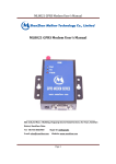
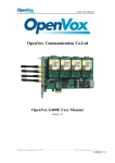
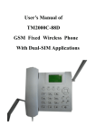
1
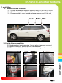
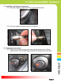
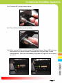
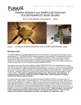
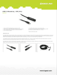
In-Vehicle Amplifier Systems
Users Guide
&
Installation Manual
MODEL : AVHR-5000
In-Vehicle Amplifier Systems
- Content 1. General Information
1.1 Precautions
1.2 Features
2. System Components
3. Installation
3.1 Outside Antenna Installation
3.2 Inside Antenna Installation
3.3 Amplifier and Antenna Connection
3.4 Operating Instructions
4. Trouble Shooting
4.1 LED Alarm
4.2 Insufficient Outside Signal Problem
4.3 Vehicle Battery Discharge Problem
5. Specification
5.1 Amplifier Specification
5.2 Outside Antenna Specification
5.3 Inside Antenna Specification
5.4 Cigarette Power Code Specification
6. Certificates
7. Memo
Page 1
In-Vehicle Amplifier Systems
1. General Information
1.1 Precautions
Reference: Direction/Information for the proper operation
Caution:
Information for users to avoid malfunctions
Warning:
Instructions for users to avoid unexpected hazard
1.1.1 Do not drop the device
- It may damage the product and its function
1.1.2 Do not place near magnetic materials
- It may cause of possible malfunction
1.1.3 Product is recommended to be used with the cigarette power cord.
For any alternative cable use, please ask professional installers.
- There is a high risk of frying up the device if inaccurately powered.
1.1.4 Please unplug both Cigarette Power Supply and Fuse Cable during
non-operation to avoid any possible battery discharge.
1.1.5 Install the product where it is recommended
- It may not properly operate on unadvised location
1.1.6 Do not repair or remodel
- It may cause malfunction. Please contact your store representative
if there is a problem
1.1.7. Do not install device while driving
- Please avoid any activities that may cause careless driving
1.1.8 Turn off the ignition before set up the device.
1.1.9 Do not install the device near any air bags in a car
- It may cause severe damage if air bags explode.
1.1.10 Do not touch the device with wet hands
- It may cause possible risk of an electric shock
1.1.11 Keep the installation location of inside and outside antenna clean
- Please organize cable lines and antenna locations to avoid any
possible interference while operating a vehicle.
1.1.12 Stop and Turn Off the device immediately if a smog comes out of
the product or any strange odor is detected from the product
- Do not attempt to fix the device. Please contact your store
representative
Page 2
In-Vehicle Amplifier Systems
1.2 Features
1.2.1 Summary
The device may be installed on cars, trucks, trailers, boats and homes to
improve user’s cellular signal.
I.
II.
III.
IV.
Decrease dropped call
Increase 2G/3G/4G data speed
Battery life extension
Voice quality improvement
It is a RF type amplifier for Cellular 800MHz and PCS1900MHz signal
enhancement. It covers GSM, CDMA, WCDMA, DSC mobile phone users.
(Please see page 11 for Operating Frequency)
1.2.2 Features
I.
Strong coverage area
- Gain 55dB
II. Automatic Overload Protection & Detection System
- Plug and Operate Systems
III. IS-95A Spurious Specifications with 25dBm(0.3W) Output power
- Provides High Data Communication rate
IV. Complete Repeater Kit.
- All components included for installation
V. Dual Band Frequency Broadband
- 800MHz / 1900MHz
VI. LED Alarm System
VII. GUI(Graphic User Interface)
- Please ask professional installers about GUI program.
VIII. Cost Effective Application for Vehicles, Boats, and Homes
- For any Home & Boats applications, optional antennas (inside &
out) and connectors may be required.
Page 3
In-Vehicle Amplifier Systems
1.2.3 Installation
2. System Components
② AVHR-5000
① Inside Antenna
④ Cigarette power adapter
③ User Manual
⑤ Outside Antenna
▣ System Components
① . Inside Antenna: connects signal between mobile phone and amplifier
②. AVHR-5000: amplifies signal by receiving base station signals through
Outdoor antenna to In-door Antenna
③. User Manual: shows how to operate system
④. Cigarette Power Adapter: Power Source
⑤. Outside Antenna: connects signal between base station and amplifier
Page 4
In-Vehicle Amplifier Systems
3. Installation
3.1 External Antenna Installation
3.1.1 Outside antenna has magnetic feature to mount on the roof of vehicle
3.1.2 Outside antenna distance should be at least 5 feet from inside antenna
3.1.3 Recommended to mount outside antenna near rear end of the roof.
Good
Better
Best
3.2 Inside Antenna Installation
3.2.1 Inside antenna is self adhesive. You can place it wherever you want
3.2.2 Before installation, please remove attached paper
3.2.2 Recommended to mount indoor antenna near suggested area as below
Page 5
In-Vehicle Amplifier Systems
3.3 Amplifier and Antenna Connection
3.3.1 Place the amplifier under the seat or appropriate location.
3.3.2 Connect inside antenna connector to Amplifier.
3.4 Operating Instructions
3.4.1 Plug in the cigarette power cord and press the button to turn ON as
shown below. The red LED light should be ON indicating its operation.
Page 6
In-Vehicle Amplifier Systems
3.4.2 Connect DC Jack as shown below
3.4.3 Turn ON the Switch as shown below
3.4.4 After turning ON the switch, green LED light will be on. Green LED indicates
that system is in a normal mode. Green and Red LED will flash 3 times
simultaneously. After the initial loading, the green LED light will be on during
operation.
Page 7
In-Vehicle Amplifier Systems
4. Trouble Shooting
4.1 LED Alarm
Cellular
PCS
Item
GREEN LED
RED LED
Problem Reference
Setting/Resetting
ON (after 3 times blinks)
3 times blinks
See 4.1.1
Normal Mode
ON
OFF
See 4.1.2
Overload
Blink( once)
-
See 4.1.3
Oscillation
Blink(twice)
-
See 4.1.4
Insufficient
Isolation
Blink(3 times)
-
See 4.1.5
Alarm
Checking
Blink(Consecutively)
-
See 4.1.6
Overload
-
Blink( once)
See 4.1.3
Oscillation
-
Blink(twice)
See 4.1.4
Insufficient
Isolation
-
Blink(3 times)
See 4.1.5
Alarm
Checking
-
Blink(Consecutively)
See 4.1.5
4.1.1 ① Check if the LED light is ON, on the cigarette power adapter
② Verify that DC cord is connected correctly
4.1.2 ① Green LED light is normal mode. If it blinks 2-3 times in a few
seconds, please see 4.1.3 ~ 4.1.6
4.1.3 ① This is normal mode that checking on input power signal and shows
signal status to users.
② It will go resume normal operation mode after Overload Detection.
4.1.4 ① There is an oscillation between inside and outside antenna.
② This status is caused by surrounding structural interferences that can
temporarily disturb mobile signals. The amplifier will auto detect available
signals as you drive to other locations. The Green LED light will turn ON
once normal mode resumes.
Page 8
In-Vehicle Amplifier Systems
4.1.5 ① The isolation may occur between inside and outside antenna
② If LED light blinks three times during installation, move the inside and
outside antenna away from each other and RESTART the amplifier.
③ If LED light blinks three times after the installation, it could be caused
by surrounding structure.
The device will auto adjust as vehicle moves.
4.1.6 ① The Overload Protection System includes the following:
AGC (Automatic Gain Level Control)
AIC (Automatic Isolation Detection)
ASC (Automatic Reset Control)
② During Alarm checking process, the Amplifier may not operate
4.2 Insufficient Outside Signal Problem
Even after installation, if there is no base stations around your
vehicle (Ex. No Service Enabled Zone), you may not receive any cellular
signals.
4.3 Vehicle Battery Discharge Problem
Verify cigarette power adapter has LED light ON as shown below. If not, check
either vehicle key is appropriately positioned or engine is ON. In case of
battery discharge, replace the battery.
Page 9
In-Vehicle Amplifier Systems
5. Specification
5.1 Amplifier Specification
Items
Cellular
PCS
Remarks
Downlink
869 ~ 894 MHz
1930 ~ 1990 MHz
Uplink
824 ~ 849 MHz
1850 ~ 1910 MHz
Downlink
55dB±2.0dB
55dB±2.0dB
Uplink
55dB±2.0dB
55dB±2.0dB
Downlink
+10dBm
+10dBm
Uplink
+25dBm
+25dBm
Downlink
< 5dB
< 5dB
Uplink
< 5dB
< 5dB
Downlink
< 5dB
< 5dB
Frequency Center
Uplink
< 5dB
< 5dB
Frequency Center
Downlink
+10dBm ±1dB
+10dBm ±1dB
Uplink
+25dBm ±1dB
+25dBm ±1dB
Downlink
+10dBm ±1dB
+10dBm ±1dB
Uplink
+25dBm ±1dB
+25dBm ±1dB
Operating Frequency
Gain
Output Power Level
@ 1FA
Ripple
Noise Figure
ALC Level
Shutdown Level
@ 1FA
After ALC
-45dBc/30kHz @±885KHz
@PCS
Spurious
Downlink
&
Uplink
-50dBc/30kHz @±1.98MHz
-45dBc/30kHz @±750KHz
@Cellular
-50dBc/30kHz @±1.98MHz
VSWR
< 1 : 1.8
Propagation Delay
< 1us
Frequency Stability
≤ ±0.05ppm
GUI Interface
RS-232C
Isolation Detection Range
45dB ~ 65dB
Only Uplink Shutdown
≥ -45dBm ±1dB @ downlink Input Signal
For BTS Protection
Input Voltage
6.0Vdc / 3.5A
Cigar Charger ‘s Vdc
Power Consumption
6.0Vdc / 840mA
@ No call
RF Connector Type
FME-male
Operating Temperature
-40°C ~ +50°C (-40°F ~ 122°F)
5.5”*4.8”* 1.4”
Size(L*W*H)
(140.7 * 123 * 35.5 mm)
Page 10
In-Vehicle Amplifier Systems
5.2 Outside Antenna Specification
Items
Cellular
PCS
Remarks
Operating Frequency
820 ~ 890 MHz
1710 ~ 1990 MHz
-
Bandwidth
70MHz
170MHz
-
Gain
5dBi
-
VSWR
≤ 2.0 : 1
-
Impedance
50 Ω
-
Max Power-W
50W
Polarization
Vertical
-
Connector
FME(Female)
-
Antenna Length
11.02 inch (28Cm)
-
Weight
0.485 lb (220g)
-
Cable Length
16.4 ft (5M)
-
5.3 Inside Antenna Specification
Items
Cellular
PCS
Remarks
Operating Frequency
820 ~ 890 MHz
1710 ~ 1990 MHz
-
Bandwidth
70MHz
170MHz
-
Gain
VSWR
2dBi
≤ 2.0 : 1
< 1 : 1.7
-
Impedance
50 Ω
Max Power-W
25W
Polarization
Vertical or Horizontal
-
Connector
FME(Female)
-
Weight
0.11 lb (50g)
-
Cable Length
6.56 ft (2M)
-
Length
4.73 inch (12cm)
-
Page 11
In-Vehicle Amplifier Systems
5.4 Cigarette Power Code Specification
5.4.1 Input Specification
Items
Min
Typical
Max
Normal DC Input Voltage
12V
-
24V
DC Input Voltage Range
12V
-
24V
DC Input Voltage Current
-
-
3.0A
Items
Min
Typical
Max
Normal DC Output Voltage
-
6.0Vdc
-
DC Output Voltage Range
5.7Vdc
-
6.3Vdc
Load Current Range
-
-
3.5A
Ripple
-
-
350mV
Over Current Protection
4.2
-
7.0A
Short Circuit Protection
-
Yes
-
5.4.2 Output Specification
6. Certificates
6.1 FCC Certification
▪
▪
6.2 IC Certification
▪
▪
Page 12
In-Vehicle Amplifier Systems
7. Memo
Page 13