1
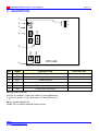
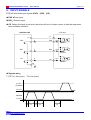
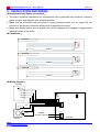
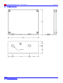
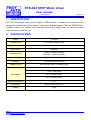
STD-402 STEP Motor driver User manual (DOC NO:050331) Page 1 of 5 1. INTRODUCTION The STD-402 stepper motor driver is bipolar, PWM chopper, constant current regulated unit, designed to operate with a wide range of step motors. Manufactured by TAILY AUTOMATION, Is suitable to drives 2 or 4 phase step motor, the driver is high torque, easy to interface and use, high performance and low cost. 2. SPECIFICATIONS Model STD-402 Suitable motor 2 or 4 phase stepper motor Control mode Bipolar, PWM constant current regulation Drive current 2A (MAX) Excitation mode Full step 2 phase excitation Half step 1-2 phase excitation Power input AC30V 50/60HZ or DC40V 100VA Selection “Full step/Half step” selection Standby current Automatically reduce at standby mode Current adjustment Maximal output current adjust PUS:Pulse input Input signals DIR:Direction input CO:Current off input Ambient temperature 0℃~40℃ Dimension 86(W)×75(D)×35(H) mm Weight 120g έᚊཝҋજ̼ѣࢨ̳Φ TAILY AUTOMATION CO.,LTD. STD-402 STEP Motor driver User manual Page 2 of 5 3. DESCRIPTION 1 H CN4 CN1 4 F 1 3 JP1 VR1 LED 2 1 CN2 1 5 CN5 CN3 1 6 STD-402 NO. NAME DESCRIPTION FACTORY SET 1 JP1 HALF/FULL Step mode select H 2 VR1 Maximal output current adjust 1.5A 3 LED Power indicate 4 CN1 Pulse input connector 5 CN4 Step motor connector 6 CN5 Power input connector Step mode selection H:JP1 at H position = HALF step mode (0.9˚/step,400step/rev). F:JP1 at F position = FULL step mode (1.8˚/step,200step/rev). Out current adjustment Rotate VR1 to adjust maximal output current. έᚊཝҋજ̼ѣࢨ̳Φ TAILY AUTOMATION CO.,LTD. STD-402 STEP Motor driver User manual Page 3 of 5 4. INPUT SIGNALS STD-402 with three input signals (PUS)、(DIR)、(CO). PUS:Pulse input. DIR:Direction input. CO:when this input is low lever, the driver will turn of output current to free the step motor from excitation condition. CONTROLLER STD-402 V+ V+ R PUS PUS 5 220R 1 20mA(MAX) DIR DIR R 220R 2 20mA(MAX) CO R CO 220R 4 20mA(MAX) 0V Signals wave: T1,T2,T4 = 20us (min). T3= 2us (max). H=4~5V CCW/DIR L=0~0.5V H=4~5V CW/PUS L=0~0.5V T3 έᚊཝҋજ̼ѣࢨ̳Φ TAILY AUTOMATION CO.,LTD. T1 T3 T2 T4 STD-402 STEP Motor driver User manual Page 4 of 5 5. INSTALLATION AND WIRING Requirement and Safety precautions: 1. The driver should be operated in an environment that is protected from moisture, corrosive gases, oil mist, and airborne dust, metallic particles. 2. Make sure all connectors are connected to correct position before turn on power. Do not connect or disconnect connectors while power is applied to the driver. 3. Make sure that the power source supplies the correct voltage and is capable of supplying the required current to the driver. Connectors: 402-CN1 CN1 900mm 402-CN4 CN4 900mm 402-CN5 CN5 900mm Wiring diagram: Controller (V+) CO VR1 DIR JP1 F LED PUS CN1 1 A CN4 COM-A 1 A B COM-B B STEP Motor έᚊཝҋજ̼ѣࢨ̳Φ TAILY AUTOMATION CO.,LTD. POWER AC 30V or DC 40V H CN5 1 STD-402 STD-402 STEP Motor driver User manual Page 5 of 5 6. DIMENSION 75.0 86.0 13.0 22.0 M4 X 2 13.0 έᚊཝҋજ̼ѣࢨ̳Φ TAILY AUTOMATION CO.,LTD. 47.0 26.0