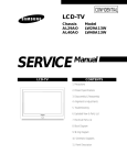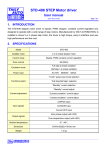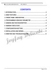
1
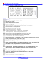
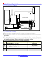
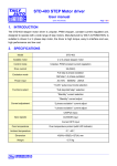
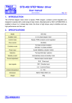
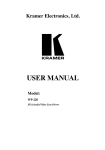
CNC-210A Series H6381 User manual DOC NO:050603 1. INTRODUCTION...................................................... 2 2. MAIN FEATURES .................................................... 2 3. FRONT PANEL DESCRIPTION .............................. 3 4. PROGRAMMING WINGING PARAMETER ............ 5 5. WINDING EXECUTION ........................................... 6 6. CONFIGURATION SETTING................................... 7 7. INSTALLATION AND WIRING .............................. 10 8. ADJUSTMENT....................................................... 13 9. MAINTAIN AND TROUBLESHOOTING................ 14 έᚊཝҋજ̼ѣࢨ̳Φ TAILY AUTOMATION CO.,LTD. 1 2 CNC-210A Series H6381 User manual 1. INTRODUCTION CNC-210A is a series of COIL WINDING MACHINE CONTROLLER developed by TAILY AUTOMATION. It not only retains all the features of previous designs, it also has a low noise level and is less sensitive to external power fluctuation. Furthermore, it also includes a RS-485 network interface, making coil-winding operation easier to manage. CNC-210A also features an integrated design: putting stepper motor driver, DC motor speed controller, brake and power supplier control circuits into one control box, simultaneously achieving size reduction, high performance and low cost. CNC-210A Series offers two different models, depending on whether a close-loop driver is provided for various applications. Model Winding Spindle Guiding Traverse CNC-210AS Drive 0.5hp DC motor in directly. Drive two phases 2A STEP motor in directly. Drive two phases 2A STEP motor in directly, External connect winding spindles CNC-210AE Or external connect guiding traverse STEP motor driver. motor driver. 1.1. Software edition H6381 Edition is design for Toroidal coils manufacturing equipments H6881 has two different running processes, being applicable to the toroidal coil winding machine and toroidal coil taping machine respectively. The running process is select by CONFIGURATION SETTING (page 6). If selected the taping process, the [Brake] output become the [scissors] output, the winding parameter [Degree] become the [Tape storing turns]. During wrapped if the turns reach to the [Tape storing turns], the [scissors] will output for one second to clipping tape. 2. MAIN FEATURES Single chip Microprocessor design, has further higher performance and higher functions; it also has less sensitive to external power fluctuation or to external electromagnetic interference. Memory use FLASH ROM, capacity capable storing up to 1000 steps winding data, 9 winding parameters, and 5 options can be independently assigned for each step. Off-power memory retention without battery. Winding speed can be specified using the front panel keypad, resulting in easy programming of multi-step, multi-speed settings. Guiding traverse step motor with constant-current drive offering fast wire guiding speeds. Guiding traverse offering 10 steps moving speed selection. Offering RS-485 interface for PC linking and data transfer. Software can be update through the personal computer. Power input AC100V~120V、220V~240V 600VA(max). έᚊཝҋજ̼ѣࢨ̳Φ TAILY AUTOMATION CO.,LTD. 3 CNC-210A Series H6381 User manual 3. FRONT PANEL DESCRIPTION 3.1. Key pads ~ :10 key, for entering numerical values. :Enter into EDIT mode. :Specify target production quantity. :Specify starting step. :Specify ending step (in taping process, this function is invalidation). :Select parameter to be programmed. :Select guiding direction for each step. :Select winding direction for each step. :To specify whether to store or spread wire for each step. (In taping process, always running spread function). :Select whether to have auto-positioning function for each step. :Select whether to have auto-starting function for each step. (in manual mode, this function is invalidation). :Reduce step number, or press down for two seconds to reduce production counter. :During programming, clear current data to zero. :Copy the data of previous step into current step. :Write data into memory. :Switch the counter display to shows between production counter and speed (RPM). :Press down for two seconds to reset production counter to zero. :Switch between automatic and manual mode. :Winding process,switch the brake between lock and unlock during motor stop. Taping process,switch the scissors between on and off during motor stop. :Skip current step and go to the next step. :Discard current step and go to the previous step :At any time, discontinues current operation and return to ready mode. :Pause during winding. :Restart during pause, or pause during winding. έᚊཝҋજ̼ѣࢨ̳Φ TAILY AUTOMATION CO.,LTD. 4 CNC-210A Series H6381 User manual 3.2. Digital display STEP DISPLAY:Show the current step number being wound or being programmed. DATA DISPLAY:During programming, in combination with LED, shows the parameter being programmed. During winding or ready mode, show the current number of turns. COUNTER DISPLAY:Shows production counter and winding speed ( RPM). 3.3. Status indicators ś!READY :Lit means in READY mode, flash means PAUSE mode, not lit means winding or programming in progress. ś!RUN :Lit means winding in progress; not lit means not in progress. ś!SLOW :During winding, lit means low speed winding; not lit means high speed winding. ś!MOVE :Lit means guiding roller is moving to the starting position. ś!O.S :No function. ś!LAN :Lit, means currently communicating with network. ś!FINISH :Lit, when reaching the preset piece count. ś!RPM :Lit means the counter display shows RPM. ś!QTY :Lit means the counter display shows the production counter. 3.4. Winding parameters definitions □ □ □ □ O.D. I.D. PITCH TURNS :Cores outer diameter.[Setting range 0.00~999.99mm]。 :Cores inner diameter.[Setting range 0.00~999.99mm]。 :Diameter of the copper wire.[Setting range 0.000 ∼ 9.999mm]。 :Total length to be store / Total number of turns to be wound. [Setting range 0∼ 99999]。 □ DEGREE :Start spreading position of the core.[Setting range 0~360°]. □ WIDTH :Spreading region,[Setting range 0~360°]; □ H.S. □ L.S. □ SLOW Tape storing turns,[Setting range 0~999]. :High speed. [Setting range 0~99]. :Low speed.[Setting range 0~25]. :Number of turns to be done at low speed prior to stop [Setting range 0∼999]. έᚊཝҋજ̼ѣࢨ̳Φ TAILY AUTOMATION CO.,LTD. 5 CNC-210A Series H6381 User manual 4. PROGRAMMING WINGING PARAMETER 4.1. MEMORY REGION SELECTION CNC-210A contains 1000 memory step, by defining the region, users can effectively manage the memory. Various winding parameter can be stored in different regions and can be retrieved instantaneously. After specifying the regions, programming and winding can be done in those regions; all un-selected regions will retain their original contents and unmodified. When setting the STEP number, the Ending step number must be larger than the Starting step number, or the winding operation will not start Specifying starting step In ready mode, press to selected. [Setting range 0 ~ 999]. Specifying ending step (in taping process, this function is invalidation). In ready mode, press o selected. [Setting range 0 ~ 999]. 4.2. Programming winding parameter In READY mode, press invokes the programming mode. The STEP DISPLAY shows START STEP number, the parameter indicator 『O.D.』lit, the DATA DISPLAY shows『O.D』setting value. The value can be change by pressing numerical keys followed by key. After that the STEP number will automatically increase by one, to continue set the『O.D』for next step. When the STEP number larger then the END STEP number, the STEP number will restore to the START STEP number and the indicator light will change from『O.D.』 to 『I.D.』 for user to specifying the 『I.D.』for each STEP. Repeat the same procedure using numerical keys and the key, all winding parameters for each STEP can thus programmed. The following functions are also available: :Select guiding direction, forward or reverse. :Select the winding direction, clockwise or counter-clockwise. :Specify whether to store (light) or to spread (not light) wire for each step. :Select whether the guiding roller move to the starting position automatically or upon a manual pressing of the key. :Select whether to have auto-start function for each step. :Clear the current value to zero. :Copy the content of the previous step to the current step. :Go back to the previous programming step. :Scroll through different parameters. Each time when modify the Parameters and selections, key must pressed to effect the change. έᚊཝҋજ̼ѣࢨ̳Φ TAILY AUTOMATION CO.,LTD. 6 CNC-210A Series H6381 User manual 4.3. Running mode Continual mode 、[WIDTH]、 Before it begins winding, if『DEGREE』of the step set as 999, then the 『DEGREE』 [FEED DIR] won't be re-read. The values are not changed, that is the wire guide motor will continue guiding wires from the current position. The width and left-right margins are the same as the ones of the previous section. Both the wire-guiding and winding directions are not changed either. This mode especially suits to winding which have the multiple drawing tops in the same sets of coils. Without WIDTH mode Before it begins winding, if『WIDTH』of the step set as 0 or 999, means without WIDTH mode ,When start winding the guide motor will guiding wires on the one direction till finish winding total turns . 4.4. Clear all winding parameter In the READY mode, press will clear all the winding parameter in the memory. Be cautious in using this function or all the data will be lost. 5. WINDING EXECUTION 5.1. To start winding After set up all data items, press key, the winding process begins in accordance with the set-up content. Press key to pause winding. During winding, press the key, the winding speed can be switch between high speed and low speed. The following key functions are available during PAUSE mode: :Give up the numbers of the winding turns and regress one step. :Finish current step and proceed to next step. :Continue winding. :Give up winding and go back to the READY mode. 5.2. Winding speed (RPM) display Pressing key will cause the counter display to shows the winding spindle running speed (RPM) without interrupting the counting. Pressing again will change to shows production counter. έᚊཝҋજ̼ѣࢨ̳Φ TAILY AUTOMATION CO.,LTD. 7 CNC-210A Series H6381 User manual 5.3. Production counter management Each time the running process goes from the START STEP to the END STEP, the production counter will automatically increase by one. Preset counter: In READY mode, press key and then key in desired values followed by the key. When the production counter reaches the value, the FINISH led lit. [Setting range 0~99999]. Decrease production counter: During READY or PAUSE mode, press the key and hold down for two seconds the production counter will decrease by one. Reset production counter: Holding down key for two seconds, it will reset the production counter to zero. 6. CONFIGURATION SETTING In the READY mode, press the following keys combination as section [6.1. ~6.4], the DATA DISPLAY will show corresponding setting value. If no change is necessary, press the key get back to READY mode. Or press numerical key followed by the key to changed parameter. 6.1. Winding mode selection In this function the STEP display and the DATA display will shows eight digits, representing eight winding mode selections respectively. Press numerical keys as below to set each digit. 5 4 3 2 1 Moving speed: Select the moving speed when guiding roller move to the start position. 0 represents high speed; 1 represents low speed. Press to select. jogging speed: Select the jogging speed of guiding roller when press LEFT and RIGHT button. 0 represents high speed; 1 represents low speed. Press to select. Operation mode: Select operation mode for the START switch. 0 represents ON/OFF mode; 1 represents Trigger mode. Press The key on the panel always as trigger mode. Running process: to select. Select the running process to meet different functions requirement. 0 represents winding process; 1 represents taping process. Press έᚊཝҋજ̼ѣࢨ̳Φ TAILY AUTOMATION CO.,LTD. to select. 8 CNC-210A Series H6381 User manual 6.2. Station number Set the station number of the winding machine controller. This number is used to identify the station when using RS-485 communication function. Up to 32 stations can be operated on the same network. [Setting range 01~99] 6.3. Guiding roller moving increment The moving increment setting value must be according to the guiding roller diameter(mm)、the gear ratio between step motor and guiding roller. (Please reference the following formula). Setting value = [(roller diameter × 3.1416)÷(gear ratio × 400)]×100000. For example: The gear ratio between step motor and guiding roller=1:3. The guiding roller diameter=25.0mm. Setting value = [(25× 3.1416)÷(3 × 400)]×100000.=6545. Reference table Gear ratio =1:3 Guiding roller diameter (mm) Setting value 10 2618 15 3927 20 5236 25 6545 30 7854 50 13090 70 18326 6.4. Acceleration times To Set the accelerate rate for the winding spindle [Setting range 00~99]. In the READY mode, press the data display shows accelerate rate setting value, If no change is necessary, press the key get back to READY mode. Or press key to get into change mode, then the value can be changed by pressing the numerical key followed by the key. 00 means shortest acceleration times ;99 means longest acceleration times. 6.5. Reset all configuration data In READY mode press keys, it will reset all the configuration data and replace by initial data. Be cautious in use this function. έᚊཝҋજ̼ѣࢨ̳Φ TAILY AUTOMATION CO.,LTD. 9 CNC-210A Series H6381 User manual 6.6. Data transmit The CNC-210AS has a RS-485 serial communication interface, can be used to send the winding data to the others station. Up to 32 stations can be operated on the same network. In this function, set station numbers to the controllers to recognize the controller to which the current data is being send. (Refer to the section 7.2. station numbers.) The communication bus wiring diagram as below: CNC-210AS CNC-210AS CNC-210AS EARTH RS-485 CONNECTION BOX RS-485 CONNECTION BOX RS-485 CONNECTION BOX LAST STATION PREVIOUS STATION COOMUNICATION CABLE(6P4C) COOMUNICATION CABLE(6P4C) TERMINATOR RESISTOR 47~100ohm In READY mode press following keys combination, its will sent each setting data to target station. :Sends configuration setting data to the specify station. :Sends winding parameters to the specify station. :Sends password to specify station. It will sends from START STEP to END STEP, during sent the winding parameters, Represents target station number. If the target station number specify as “00”, all the stations on the same network will receive the data is being sent. έᚊཝҋજ̼ѣࢨ̳Φ TAILY AUTOMATION CO.,LTD. 10 CNC-210A Series H6381 User manual 7. INSTALLATION AND WIRING The controllers should be operated in an environment that is protected from moisture, corrosive gases, or liquid, and free from airborne dust, metallic particles, and magnetic noise. Do not block the intake/exhaust ports of the controller. Otherwise, a fault may occur. Make sure that the power source supplies the correct voltage and is capable of supplying the required current to the controllers. Do not connect or disconnect wires and connectors while power is applied to the controller. Make sure the machine and controllers are properly grounded. Make sure that the leads and connectors are connected correctly. Normally operate under 10℃ ~ 40℃ environment; over 40℃ should perform under good ventilation, avoid heating. 7.1. Accessories All items of accessories are optional to purchased. ITEM 210A-CN2 210A-CN3 210A-CN4 210A-CN5 210A-CN6 210A-CN7 210A-CN8 HOME-SR CNTB-03B/C DISC START STOP RESET Foot switch Power cord NAME RS-485 Connection box Operate switches connection cable Home sensor connection cable Counting sensor connection cable I/O signal connection cable Pulse output connection cable AC output connection cable Home sensor Counting sensor Counting disc Push button switch Push button switch Push button switch RUN/STOP Foot switch AC Power cord ○ = Optional CNC-210AS ○ ○ ○ ○ ○ × × ○ ○ ○ ○ ○ ○ ○ ○ × = not use in this model έᚊཝҋજ̼ѣࢨ̳Φ TAILY AUTOMATION CO.,LTD. CNC-210AE ○ ○ ○ ○ ○ ○ ○ ○ ○ ○ ○ ○ ○ ○ ○ 11 CNC-210A Series H6381 User manual 7.2. Wiring diagram for CN2~CN6 CN3 CN4 CN5 CN6 OP1 CN6 OP2 AUX I/O CN5 +24V Turn Counter CN4 OP1 Home Sensor CN3 OP3 Operate Switches CN2 OP2 RS-485 CN7 OP3 OP4 IP1 IP2 IP3 IP4 COM C0M PHC PHB PHA +24V C0M IP6 HOME IP5 +24V +24V RESET START STOP LAMP3 LAMP2 LAMP1 TR- TR+ 0V DIR PUS +5V Pulse Output COM IP4 LEFT IP3 RIGHT JOG AUX I/O 1 2 RESET TURNS SENSOR Operate Switches 0V START b 4 2 OUT a 3 1 +24V STOP b 4 2 0V FOOT SW RS-485 a 3 1 OUT b 4 2 +24V a 3 1 LENGTH SENSOR 7.3. Wiring diagram for CNC-210AS AC Input AC AC COM A CW H 1 2 3 4 AC GND AC AC Output Winding Driver 5 AUX I/O CN6 Brake CCW Vout F+ F- 6 STEP Motor BK+ BK- A A B B 7 8 9 10 11 12 GND M A A B B EARTH AC Input Winding Spindle Motor DC24V 12W Brake έᚊཝҋજ̼ѣࢨ̳Φ TAILY AUTOMATION CO.,LTD. +24V CN8 OP4 CN5 IP1 Turn Counter CN4 IP2 Home Sensor CN3 IP3 Operate Switches CN2 IP4 RS-485 CN7 COM C0M PHC PHB PHA +24V C0M IP6 HOME IP5 +24V +24V RESET START STOP LAMP3 LAMP2 LAMP1 TR- TR+ 0V DIR PUS +5V Pulse Output 2Phase 6V 2A Guiding Traverse STEP Motor 12 CNC-210A Series H6381 User manual 7.4. Wiring diagram for CNC-210AE Drive STEP Motor in directly Turn Counter AUX I/O CN4 CN5 CN6 CN8 AC Input Winding Driver 3 4 5 6 H/L Vin 2 CCW AC Output Brake CW H CW AC 1 AC GND AC AC COM A CCW Vout F+ F- +24V Home Sensor CN3 OP1 Operate Switches CN2 OP2 OP3 OP4 IP1 IP2 IP3 IP4 COM C0M PHC PHB PHA +24V C0M IP6 HOME IP5 +24V +24V RESET START STOP LAMP3 LAMP2 LAMP1 RS-485 CN7 CN8 TR- Pulse Output TR+ 0V DIR PUS +5V CN7 STEP Motor BK+ BK- A A B B 7 8 9 10 11 12 GND CN8 COM AC GND AC Motor Driver AC AC A A M AC Output (MAX 400W) EARTH AC Input B B 2Phase 6V 2A DC24V 12W Brake Guiding Traverse STEP Motor Winding Spindle Motor External connect STEP Motor driver AC Input Winding Driver AC GND AC COM CW A H 2 3 4 5 6 H/L Vin AC 1 CCW AC Brake CCW Vout FF+ BK- A A B B 7 8 9 10 11 12 CW COM AC GND AC DIR PUS V+ Motor Driver AC AC AC AC M B AC Output EARTH (MAX 400W) AC Input Winding Spindle DC24V 12W Brake Motor έᚊཝҋજ̼ѣࢨ̳Φ TAILY AUTOMATION CO.,LTD. STEP Motor BK+ CN8 B +24V CN6 OP1 AUX I/O CN5 OP2 OP3 OP4 IP1 IP2 Turn Counter CN4 A Guiding Traverse IP3 Home Sensor CN3 Step Motor Driver 2Phase STEP Motor IP4 Operate Switches CN2 GND A COM RS-485 CN7 AC Output CN7 C0M PHC PHB PHA +24V C0M IP6 HOME IP5 +24V +24V RESET START STOP LAMP3 LAMP2 LAMP1 TR- Pulse Output CN8 CN8 TR+ 0V DIR PUS +5V CN7 13 CNC-210A Series H6381 User manual 8. ADJUSTMENT 8.1. Adjustments for CNC-210AS CL:Output current limit. 1. Connect a DC Amperes meter between terminal and DC motor as below. 2. In ready mode press to make the DC motor starting rotate and then press holding the winding spindle. 3. Rotate CL to set limited current, show on Amperes meter. ( 2A for 180v DC motor、4A for 90v DC motor). to (The CL have been set by factory before delivery. Only adjust it when change DC motor and replace 210A-DVR driver board.) IR:Torque compensation. 1. Set the winding parameter H.S.、 L.S. in 20, then press to change the DISPLAY shows RPM. Then press key to start winding. 2. Rotate IR potentiometer to make it in same speed during the winding spindle shaft in full-load and unload. Then press key to stop winding. MAX:Maximum winding speed. 1. Set the winding parameter H.S., L.S. in 99, and press key to change the DISPLAY shows RPM. Then press key to start winding. 2. Rotate MAX potentiometer to make the winding speed (RPM) as you want. Then press key to stop winding. DC MOTOR 10A AMPERE METER 0 M 10 10 FUSE2 FUSE1 CN2 RY1 CN1 COIL-24V-DC SCL-DPDT A CN5 L T1 R32 T1 POWER T1 CL AC 100~120V TF808C1 AC 220~240V TF808C2 H R38 C33 R33 CL L H I R MAX IR R33 POWER L MAX CN4 CN3 H TAILY AUTO 210A-DVRID:XXXXXX έᚊཝҋજ̼ѣࢨ̳Φ TAILY AUTOMATION CO.,LTD. R33 AC 100~120V 82K AC 220~240V 47K 14 CNC-210A Series H6381 User manual 8.2. Adjustments for CNC-210AE Speed Mode selection To select the speed signal output mode for winding driver. Selected by JP1. 1. V-out mode:Represents the speed signal with DC 0~10v output. 2. H/L mode:Represents the speed signal with HI/LOW lever output. Hi speed with HI lever, low speed with LOW lever. V-out adjust 1. Set the winding parameter H.S., L.S. in 99, and press key to change the DISPLAY shows RPM. Then press key to start winding. 2. Rotate Vout potentiometer to make the winding speed (RPM) as you want. Then press key to stop winding. 3. This function only worked in Vout mode. COM CW RUN CCW F/R Vout H/L TB1 8 7 6 5 4 3 2 1 CN1 12 11 10 9 CN2 FUSE2 FUSE1 CN5 T1 AC 100~120V TF808C1 H/L Vout AC 220~240V TF808C2 JP1 L VR1 H JP2 JP3 CW_CCW JP2 JP3 Control Mode RUN_F/R CW RUN CN6 JP1 Speed Mode Vout ADJ. H/L Vout 1 2 3 T1 AC POWER R32 T1 CCW F/R CN4 CN3 9. TAILY AUTO 210A-EXD ID:XXXXXX MAINTAIN AND TROUBLESHOOTING 9.1. Error message When a fault occurs during operation, the DATA DISPLAY shows error massage, stop winding and then RESET go back to the READY mode. Err-0: The parameters or data in memory are fault. Err-5:RS-485 communication error. Err-p:Password error, key in 4 numbers password before edit. έᚊཝҋજ̼ѣࢨ̳Φ TAILY AUTOMATION CO.,LTD. 15 CNC-210A Series H6381 User manual 9.2. Internal wiring diagram CN6 210A-CNB CN8 210A-CPU-CN4 CN5 CN4 CN9 210A-CPU-CN2 CN7 2 1 210A-DVR-CN5 CN3 CN2 2 1 MHB-2S CN5 MHB-2S CN1 CN2 CN3 CN3 210A-CPU-CN3 TB1 CN4 210A-DVR/210A-EXD 4 3 2 1 CN2 CN1 MHS-4S MHB-2S MHB-3S 210A-DVR-CN2 210A-CPU 210-KBD CN6 1 2 3 CN5 1 2 CN1 1 2 3 4 MHB-4S 210A-DVR-CN1 CN6 MHB-3S CN2 1 2 3 CN4 3 2 1 BOOT MHB-3S CN3 4 3 2 1 CN1 2 1 CN2 1 2 2 1 XH250-2S POWER SW 1 210A-DVR-CN4 2 7 6 5 4 3 2 1 CN1 MHS-4S CN7 MHB-2S CN3 CN8 MHB-2S 210A-ECB TLP-503D MHB-7S 3 DC 12V FAN 9.3. Periodically maintain Please periodically clean up the controller inner accumulate dust and dopants. Please periodically check the wire connection between controller and machine if have loose or bad contact. The following parts must be maintained or changed periodically as list below. If any part is found faulty, it must be changed immediately even when it has not yet reached the end of its life, which depends on the operating method and environmental condition. For parts replacement, please contact your sales representative. NO Parts name Life guideline 1 COOLING FAN (DC 12V 6cm) RELAY (on the 210A-DVR driver board, it used to switching the winding direction) Carbon BRUSH of the DC motor 10,000 hours 2 3 4 5 έᚊཝҋજ̼ѣࢨ̳Φ TAILY AUTOMATION CO.,LTD. 100,000 times 1 year