1
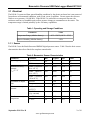
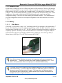
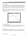
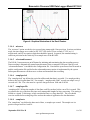
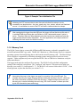
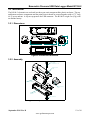
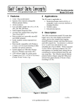
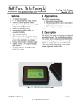
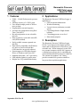
Barometric Pressure USB Data Logger Model B1100-2 1 Features • • • • • • • • • • • • • 2 Applications 30000 – 110,000 Pa barometric pressure range Absolute accuracy of ±250 Pa, max. User defined sample period of 20Hz to once per hour Programmable start and stop time Accurate time stamped data using Real Time Clock (RTC) Records temperature at user selectable intervals Data recorded to a removable microSD card (8GB included) Easily readable comma separated text data files Data transfer compatible with Windows or Linux via Universal Serial Bus (USB) interface (no special software) System appears as USB Mass Storage Device to Windows and Linux OS’s. Standard replaceable “AA” type battery LED indicator lights for system status Weighs 2oz (55g) with alkaline battery The Barometric Pressure USB Data Logger is applicable to: • GPS navigation enhancement • Weather monitoring • Vertical velocity indication (rise/sink speed) • Calculating altitude of high-altitude balloons • Calculating pressure at sea level • Educational purposes 3 Description The Barometric Pressure USB Data Logger B1100-2 uses high precision digital pressure sensor and records pressure in Pascals at a user selectable rate. When connected via the USB to a personal computer, the B1100-2 appears as a standard mass storage device containing the comma delimited data files and user setup files. The commercial standard “AA” battery provides extended life operation suitable to long term data acquisition applications. Figure 1: Barometric Pressure USB Data Logger B1100-2 September 2014 Rev D 1 of 14 www.gcdataconcepts.com Barometric Pressure USB Data Logger Model B1100-2 3.1 Electrical The B1100-2 is protected from general handling conditions by the plastic enclosure but is not protected from adverse environmental conditions, such as rain, sweat, or splashes. Do not expose the sensor to fluids or over-pressure (>10,000 hPa). If the B1100-2 is enclosed in a waterproof structure, the enclosure must have a breathable port to allow pressure changes to communicate to the sensor. The temperature range is limited primarily by the AA battery capabilities. Table 1: Operating and Storage Conditions Parameter Value Temperature Range (alkaline battery) -0°F ~ 130°F (-18°C ~ 55°C) Relative Humidity (alkaline battery) <90% 3.1.1 Sensor The B1100-2 uses the Bosch Sensortec BMP085 digital pressure sensor. Table 2 lists the basic sensor characteristics but refer to Bosch for complete sensor details. Table 2: Barometric Sensor Characteristics Parameter Operating temperature Absolute accuracy pressure VDD=3.3 V Resolution of output data Relative accuracy pressure Absolute accuracy temperature Condition Operational Min −40 Full Accuracy 0 -250 70000 - 110000 Pa (0 to +65 °C) 30000 - 70000 Pa (0 to +65°C) 30000 - 110000 Pa (-20 to 0 °C) Pressure +65 Units °C °C ±100 +250 Pa -300 ±100 +300 Pa -400 ±150 +400 Pa Temperature 70000 – 110000 Pa (@ 25°C) 0 – 65°C (@ p constant) @ +25°C -1.5 0 - 65°C -2.0 Typical Max +85 1.00 Pa 0.1 ±20.0 °C ±50.0 Pa ±0.5 ±1.0 September 2014 Rev D Pa +1.5 °C +2.0 °C 2 of 14 www.gcdataconcepts.com Barometric Pressure USB Data Logger Model B1100-2 3.1.2 Indicator LEDs System status is indicated by the two LEDs located near the USB connector. The blue LED indicates system operation and blinks once per second to indicate a properly operating system. The blue LED blinks when the B1100-2 is recording data, in standby mode, or is connected to a computer via the USB port. The red LED blinks when data is written or read from the microSD memory card. In data logging mode, the period at which the red LED blinks depends on the sample rate and other configuration settings. The LEDs will flicker during user initiated shutdown. The “statusindicators” tag in the configuration file turns off or changes the brightness of the status indicators (see section 3.1.4.11). 3.1.3 Battery 3.1.3.1 Main Battery The B1100-2 is powered by a single “AA” sized battery and will log continuously for approximately 7 days at 1 Hz, depending on system configuration and battery quality. The RTC continues to operate from the battery when the device is “off”. The RTC should be reinitialized if the battery is removed or completely depleted. The battery is not used when the device is connected to a computer USB port. Gulf Coast Data Concepts recommends an alkaline battery (ANSI type 15A or IEC type LR6) or lithium battery (ANSI type 15L or IEC FR6) to operate the B1100-2. Figure 2: Starting the B1100-2 Use a lithium primary AA battery to improve low temperature performance and extend operating time. The lithium chemistry has a wider operating temperature -40°F – 140°F (-40°C – 60°C) and about 30% more capacity over a standard alkaline battery. A 5v supply via the USB connector provides extended operation of the device independent of the internal battery. Common USB power adapters or USB battery packs for consumer electronics can provide the required 5v supply. The logger does not implement power saving features when connected to an external power supply so power consumption will be higher than when using the AA battery. September 2014 Rev D 3 of 14 www.gcdataconcepts.com Barometric Pressure USB Data Logger Model B1100-2 The logger is always “on” maintaining the real time clock and will eventually discharge the battery completely after several months. The battery chemicals will eventually leak and corrode the electronics. Remove the AA battery prior to long term storage of the B1100-2. 3.1.4 System Configuration Options The B1100-2 is configured using a set of tags and settings stored in a text file named “config.txt”, which is located in the root directory of the microSD card. The system reads the configuration file at boot time. Table 3 lists the configuration file tags. A tag is followed by an equal sign (“=”) and an applicable tag setting. A line finishes with a newline character. Tags are not case sensitive. Tab and space characters are ignored. Lines starting with a semicolon (“;”) are treated as comments and ignored by the system. The system will use the default settings listed in Table 3 if the config.txt file is not found. Do not use the Windows Notepad editor because it does not terminate new lines properly. GCDC recommends Windows Wordpad or Notepad++ to edit the config.txt file. Table 3: Configuration File Tags and Descriptions Tag Valid Settings Default deadband An integer between 0 and 32767 0 deadbandtimeout 0 microres An integer between 0 and 65535 An integer between 0 and 65535 An integer between 1 and 255 - Off rebootondisconnect - off on disconnect sampleperiod An integer between 1000 and 4194303 An integer greater than 0 Integer between 1 and 20 See section 3.1.4.9 - 2000 dwell interleave samplesperfile samplerate starttime and stoptime stoponvusb statusindicators “Normal”, “High”, “Off” 1 1 28896 Description Sets the deadband to a range expressed in Pascals. A new sample is recorded if a sensor reading exceeds the previous recorded reading by the deadband value Specifies the period in seconds when a sample is recorded regardless of the deadband setting. The number of samples recorded after a deadband threshold triggered event Number of pressure samples between temperature samples The presence of this tag sets the device to record time stamps with 0.1ms effective precision. The presence of this tag causes the system to start recording after disconnect from a USB port. The period in milliseconds between samples. Use for slow data rates. The number of lines of data per data file 2 Sets the rate at which data is collected and recorded to the microSD card. Use for fast rates >1Hz Off Defines when to start and stop recording Stops data logging if 5v USB power is present (see section 3.1.4.10) LED status indicators can be activated with normal brightness (Normal), activated with high brightness (High), or completely deactivated (Off). Normal September 2014 Rev D 4 of 14 www.gcdataconcepts.com Barometric Pressure USB Data Logger Model B1100-2 3.1.4.1 deadband “deadband” defines the minimum difference between recorded pressure sensor readings in Pascal units. A new sample from the pressure sensor must exceed the previous recorded reading before the logger records the data. The deadband value can be set to an integer between 0 and 32767. The deadband function is an effective way to reduce the amount of data collected by defining the granularity of the data. The deadband functions as a event threshold limit when used in conjunction with the “dwell” feature. Figure 3 illustrates the deadband feature filtering out small changes from the data set. Only when the deadband limit is exceeded will a new data sample be pushed to the file. Note that this feature will result in samples with inconsistent time periods. Therefore, the data sets should be re-sampled to establish uniform time periods. Figure 3: Graphical Illustration of the Deadband Feature 3.1.4.2 deadbandtimeout “deadbandtimeout” defines the period in seconds when a sample is recorded by the device regardless of the deadband setting. This feature ensures periodic data is recorded during extended periods of inactivity. A valid setting for the deadbandtimeout is an integer between 0 and 65535. 3.1.4.3 dwell The “dwell” tag defines the number of consecutive samples recorded at the set sample rate after a deadband threshold event. The deadband threshold event occurs when a sensor reading exceeds the last recorded value by the deadband setting. A valid dwell setting is an integer between 0 and 65535. September 2014 Rev D 5 of 14 www.gcdataconcepts.com Barometric Pressure USB Data Logger Model B1100-2 Figure 4: Graphical Illustration of the Dwell Feature 3.1.4.4 microres The “microres” option sets the device to record time stamps with 0.1ms precision. In micro-resolution mode, the time stamps are recorded as XX.YYYYZZ where XX are seconds, YYYY are 0.1 milliseconds, and ZZ are spurious digits that should be ignored. In general, the standard timing is sufficient precision for the relatively slow sample rates of the B1100-2. 3.1.4.5 rebootondisconnect The B1100-2 incorporates an on/off button for initiating and terminating the data recording process. Data recording is automatically started upon disconnect from a computer USB port if the tag word “rebootondisconnect” is included in the configuration file. Note that the system must first be turned on and the configuration file read before the rebootondisconnect option is implemented by the system. Subsequent disconnects will then cause a reboot and immediate data recording. 3.1.4.6 sampleperiod The “sampleperiod” tag defines the period in milliseconds that data is recorded. Use sampleperiod to define a rate less frequent than 1Hz. For example, “sampleperiod=2000” records one sample every 2 seconds or 0.5 Hz. The value must be a positive integer between 1000 and 4194304. 3.1.4.7 samplesperfile “samplesperfile” defines the number of data lines each file can have before a new file is created. This tag controls the size of the data files into easily manageable lengths for later processing. This setting is loaded as a signed 32-bit integer, which can translate into very large data files. The user should exercise caution before setting large files and test the end-user application for data limitations. 3.1.4.8 samplerate The “samplerate” tag defines the data rate in Hertz, or samples per second. The sample rate is a positive integer between 1 and 50. September 2014 Rev D 6 of 14 www.gcdataconcepts.com Barometric Pressure USB Data Logger Model B1100-2 3.1.4.9 starttime and stoptime The B1100-2 starts and stops data recording based on the times defined using the “starttime” and “stoptime” tags. The times must be in “MM HH” 24-hr format with the two entries separated by a space. Entries marked with “*” operate as a wild card. The stop time is 5 seconds after the start time unless defined otherwise by the stoptime tag. Example timing configurations: Example 1: Start recording at 12:30pm and stop recording at 6:00pm. starttime = 30 12 stoptime = 00 18 Example 2: Start recording at the beginning of every hour and stop recording at the 45 minutes later. starttime = 00 * stoptime = 45 * 3.1.4.10 stoponvusb The “stoponvusb” tag stops data logging operations when a 5v supply is detected on the USB connector. By default, the device switches power from the internal battery to the USB 5v and continues to log data. 3.1.4.11 statusindicators The brightness intensity of the LED status indicators is defined using the “statusindicators” tag and valid settings of “normal”, “high”, and “off”. 3.1.4.12 interleave Temperature is sampled from the sensor at sub-intervals to pressure readings. The “interleave” tag defines the number of pressure readings between each temperature reading. The temperature value is used to correct the pressure. More frequent temperature readings will improve the pressure accuracy. 3.1.5 Example Configuration Files Example A) The example configuration file sets the B1100-2 to record pressure twice per second with temperature interleaved every two seconds. Each data file includes one hour of data. The device will boot and begin data logging once disconnected from the host computer. ;Example B1100-2 config file ;set sample rate samplerate = 2 ;set file size to 60 minutes of data samplesperfile = 7200 ;sample temp every 4tth pressure sample ;or every 2 seconds interleave = 4 ;set status indicator brightness statusindicators = normal ;start when disconnected from PC rebootOnDisconnect ;see B1100-2 user manual for other config options Figure 5: Configuration File Example A September 2014 Rev D 7 of 14 www.gcdataconcepts.com Barometric Pressure USB Data Logger Model B1100-2 Example B) This configuration sets the B1100-2 to record pressure and temperature once every 5 seconds. Each data file will include one day of data. The logger will start when the on/off button is pressed. ;Example B1100-2 config file ;set sample rate sampleperiod = 5000 ;set file size to 1 day of data samplesperfile = 17280 ;sample temp every pressure sample interleave=0 ;set status indicator brightness statusindicators = high ;use on/off button ;comment out rebootondisconnect ;rebootOnDisconnect ;see B1100-2 user manual for other config options Figure 6: Configuration File Example B 3.1.6 Data Files The B1100-2 creates a new data file when the system is booted or when the maximum number of data lines is reached in the previous data file. A system boot condition occurs when the on/off button is pressed, 5v power is restored to the system via the USB connector, or when the B1100-2 is removed from a computer USB port with the “rebootondisconnect” feature enabled. Data files are placed in a folder named “GCDC” and are named DATA-XXX.CSV, where XXX is a sequential number starting with 001. The system will create up to 999 files. 3.1.6.1 Data Format Data is written to files in comma separated text format starting with the file header information and followed by data entries. The header describes the system configuration, firmware version, and the precise time when the file was created. Each header line is preceded with a semicolon (“;”). Table 4 lists the valid header tags. Data entries include a time stamp, the barometric sensor reading and temperature. The time stamp is seconds elapsed from the start time recorded in the header. The barometric pressure data is recorded in Pascal units. Temperature, as reported by the barometer sensor, is periodically recorded as a third column of data and is 10 times the value in °C (the decimal character is not present). The last line of the final data file records the reason for the termination, such as “shutdown: switched off”, “shutdown: low battery”, “shutdown: max files exceeded”, “shutdown: vbus disconnect”, or “connected to computer”. The line is designated as a comment with a semicolon (“;”). September 2014 Rev D 8 of 14 www.gcdataconcepts.com Barometric Pressure USB Data Logger Model B1100-2 Table 4: Data File Header Tags Tag Description Deadband A new sample from the sensor must exceed the last reading by the deadband value DeadbandTimeout The period in seconds when a sample write is forced SamplePeriod The sample period in milliseconds at which data is recorded to the microSD card Start_Time The current time when the data file was created Temperature Temperature in °C when the file was created Time, Pressure(Pa),Temp(C*10) The names of each column of data in the file Title The name of the GCDC data logger device and sensor type Vbat Battery voltage (mv) measured at the start time Version The version control information of the firmware, including unique serial number 3.1.6.2 Converting Pressure to Altitude Altitude is calculated from the pressure data using the following equation: Altitude=44330× 1− P Po 1 5.255 where Altitude = meters above baseline altitude P = pressure in Pascal Po = pressure in Pascal at the baseline altitude (mean sea level = 101325 Pa) ;Title, http://www.gcdataconcepts.com, B1100-2, BMP085 ;Version, 836, Build date, Sep 10 2014, SN:CCDC3110131FF88 ;Start_time, 2014-09-19, 17:38:25.000 ;Temperature, 30.-10, deg C, Vbat, 1396, mv ;SamplePeriod, 200,msec ;Deadband, 0, counts ;DeadbandTimeout, 0,sec ;Time,Pressure(Pa),Temp(C*10) 0.013,101190 0.201,101189 0.419,101198,302 0.606,101196 0.801,101199 1.004,101197 1.223,101196,302 1.402,101199 1.605,101228 1.808,101146 2.026,101109,302 2.206,101121 2.408,101119 2.603,101109 2.822,101111,302 Figure 7: Example Data File September 2014 Rev D 9 of 14 www.gcdataconcepts.com Barometric Pressure USB Data Logger Model B1100-2 Table 1 lists altitude readings calculated from the example data in Figure 7. The first sample is used as the baseline value Po in the calculations. Table 5: Example Data Converted to Altitude Raw Data Time Pressure Converted Data Temperature Time Altitude (m) Temperature (°C) 0.013 101190 04/19/2014 17:38:25.010 0.0 0.201 101189 04/19/2014 17:38:25.198 0.1 0.419 101198 04/19/2014 17:38:25.416 -0.7 0.606 101196 04/19/2014 17:38:25.603 -0.5 0.801 101199 04/19/2014 17:38:25.798 -0.8 1.004 101197 04/19/2014 17:38:26.001 -0.6 1.223 101196 04/19/2014 17:38:26.220 -0.5 1.402 101199 04/19/2014 17:38:26.399 -0.8 1.605 101228 04/19/2014 17:38:26.602 -3.2 1.808 101146 04/19/2014 17:38:26.805 3.7 2.026 101109 04/19/2014 17:38:27.023 6.8 2.408 101111 04/19/2014 17:38:27.405 6.6 302 302 302 30.2 30.2 30.2 3.1.7 Real Time Clock A real time clock (RTC) is integrated into the B1100-2 and is used to determine time for each line of data recorded. The RTC is set using a text file named “time.txt” located in the root directory of the microSD card. The system looks for the time.txt file upon booting. If the file exists, the time stored in the file is loaded to the RTC and the time.txt file is deleted. The time information in the time.txt file must be in the exact “yyyy-MM-dd HH:mm:ss” 24-hour format, occur on the first line, and end with a newline character. Figure 8 provides an example time.txt file that will initialize the RTC to 2:26:30 pm June 16, 2014. The time file method of setting the RTC does not require special communication drivers so it can be implemented using a simple text editor. Direct initialization of the RTC is possible but requires specific device drivers and software from Gulf Coast Data Concepts. The RTC maintains ±50ppm accuracy (-40°C to +85°C), which means that it will drift accuracy about 30 seconds every week. The RTC is powered by the battery at all times, even when the logger is “off”. September 2014 Rev D 10 of 14 www.gcdataconcepts.com Barometric Pressure USB Data Logger Model B1100-2 2014-06-16 14:26:30 Figure 8: Example Time Initialization File Initializing the RTC ensures that the start time and individual time stamps can be correlated to an absolute time – the year, month, day, hour, minute, second, and fractional second. An uninitialized or reset of the RTC will lead to indeterminate time stamps. After unplugging the logger from the USB port, the logger will load the time.txt file when it is activated either by pressing the on/off button or if the “rebootondisconnect” option is active. Therefore, there is a delay between when the time.txt was created and when the logger actually loads the time information. For most applications, this simple method of initializing the clock results in sufficient accuracy. 3.1.8 Memory Card The B1100-2 stores data to a removable 8GB microSD flash memory card and is compatible with microSD and microSDHC type cards. The B1100-2 functions as a Mass Storage Device to computer operating systems when transferring data to and from the microSD memory card. The Mass Storage Device interface is supported by all desktop operating systems and special device drivers are not required. Tablet computers may not recognize the B1100-2 due to USB device limitations set by the tablet manufacturer. The logger needs only the config.txt file to operate. The B1100-2 will use default configuration settings if the config.txt is not present. The “config.txt” and “time.txt” files must occur in the root directory (see section 3.1.4 and section 3.1.7). The B1100-2 will create a folder called “GCDC”, if not already present, to place the data files (see section 3.1.6). Interrupting the power to the logger can result in corruption of the microSD card. For example, removing the logger from the USB port during file transfers to the PC. Reformat the card if it becomes corrupted (FAT32 file structure). If data transfers to/from the card become slow, consider formatting the card using “SD Card Formatter” software provided by the SD Association (www.sdcard.org). September 2014 Rev D 11 of 14 www.gcdataconcepts.com Barometric Pressure USB Data Logger Model B1100-2 3.2 Mechanical The B1100-2 electronics are enclosed in a three-part semi-transparent blue plastic enclosure. The top and bottom enclosure components and the printed circuit board are secured together with a 0.75” long #6-32 screw and nut. A slip-on cap protects the USB connector. The B1100-2 weighs 2oz (55g) with an alkaline battery.. 3.2.1 Dimensions 1.04 4.10 1.01 Figure 9: Enclosure Dimensions 3.2.2 Assembly 0.75" Length #6-32 Machine Screw PCB Enclosure (Top) Printed Circuit Board PCB Enclosure (Cap) PCB Enclosure (Bottom) #6-32 Hex Nut Figure 10: Exploded View of the B1100-2 September 2014 Rev D 12 of 14 www.gcdataconcepts.com Barometric Pressure USB Data Logger Model B1100-2 4 Software The B1100-2 records data to comma delimited text files and uses text based files for configuration settings. Therefore, no special software is required to utilize the B1100-2. For data analysis, Gulf Coast Data Concepts recommends using a commercial or open source mathematics package, such as MatLab, Microsoft Excel, OpenOffice Calc, Octave, R, or similar applications. 5 Troubleshooting Problem Resolution I press the on/off button but the logger does not appear to activate and no LEDs blink. Install a new battery. The logger could be operating correctly but the status indicators are turned off. Check the “statusindicator” option in the config.txt file. I press the on/off button, the blue LED blinks The deadband setting is set too high and the once per second but the red LED does not indicate logger is waiting to detect an event. logging. The logger is in standby mode waiting for a start time to occur. Check the config.txt file for the start/stop settings. The blue LED blinks slowly. The microSD card is not present or is corrupted. Check that the card is inserted properly and the card is not corrupted. I press the on/off button but the logger records only for a short period of time. Install a new battery. The microSD card is full and data files must be deleted. The logger seems to ignore the config.txt file and Check that the config.txt file is properly formatted use default settings. and not corrupted. Each setting should occur on a separate line. Some IT organizations implement an automatic encryption of all removable media devices. This will encrypt the config.txt file and the logger will not be able to access the file. Do not allow encryption of the device. September 2014 Rev D 13 of 14 www.gcdataconcepts.com Barometric Pressure USB Data Logger Model B1100-2 Problem Resolution I plug the logger into a USB port but the PC does The microSD card is not present in the logger or not indicate an external drive present. is not inserted properly. Check that the card is fully inserted into the logger. The microSD card is corrupted or damaged. Reformat the card or replace the card. The on/off button could be jammed in the plastic enclosure and the logger is stuck in the “off” state. Check that the button moves freely and “clicks” when pressed. The USB connection could be faulty or the extender cable (if present) could be faulty. Remove the extender cable and plug the logger into another USB port. The start time in the data file header is incorrect. Initialize the RTC. September 2014 Rev D 14 of 14 www.gcdataconcepts.com