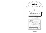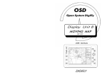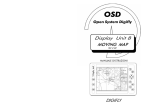
1
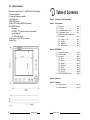
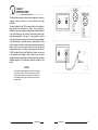
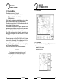
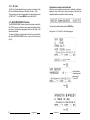
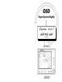
OSD
Open System Digifly
Display Unit 7
MOVING MAP
SW 2.02
USER MANUAL
DIGIFLY
5.2 - Technical features.
- Monochrome,high resolution 7", 320x240-pixel LCD, backlighted;
- Antiscratch protection;
- Contrast and brightness regulation;
- Lighted keyboard;
- Digifly OSD interface;
- External GPS interface (NMEA-0183 protocol);
MOVING MAP features
- 100 marks;
- DST, BRG, TTG to the cursor and to the destination
(current waypoint);
- GS, TRK of the Aircraft;
- Power source: 10 to 28 VDC (0.4 ampere);
- Weight: 550 g.;
Table of Contents
Chapter 1 - Introduction (Open System Digifly)
Chapter 2 - Getting started
2.1 - Front panel ............................................. pag.
2.2 - The display ............................................. pag.
2.2.1 - Navigational data section ..................... pag.
2.2.2 - Cartographic section ............................ pag.
Information on airports and radio-aids
2.3 - The keyboard .......................................... pag.
2.3.1 - Turning on / off ............................... pag.
2.3.2 - Contrast .......................................... pag.
2.3.3 - Brightness ....................................... pag.
2.3.4 - Basic functions ................................ pag.
Chapter 3 - MOVING MAP
3.1 - Cartographic symbols ............................. pag.
3.2 - General symbols ..................................... pag.
3.3 - Main menu' ............................................. pag.
3.3.1 - Go To .............................................. pag.
3.3.2 - Save fix ........................................... pag.
3.3.3 - Nearest ........................................... pag.
3.3.4 - Data Base ....................................... pag.
3.3.5 - Set Up ............................................ pag.
3.3.6 - Gps Page ....................................... pag.
3.3.7 - PC Link .......................................... pag.
3.4 - DEAD RECKONING Function .................. pag.
3
3
4
4
7
7
7
7
8
10
11
11
12
12
12
13
15
18
20
20
Chapter 4 - System test
Chapter 5 - Installation
5.1 - Electrical Wiring ...................................... pag. 22
5.2 - Technical features .................................... pag. 24
24
Manuale Utente
Manuale Utente
I
chapter 1
INTRODUCTION
The Moving Map navigation system makes navigation on electronic
mapping extremely accurate in any environmental and light
conditions.
The point obtained by the GPS is viewed directly on the electronic
map together with information on speed, route, and time to
destination. The system’s graphic memory stores the latest 200 points
of the track followed by the aircraft at user-defined intervals and
waypoints associated to route legs. It is also possible to position
marks and store them in memory. As for the electronic map contained
in the data cartridge, it is possible to view a representation of all the
useful elements contained in nautical and aeronautical maps with
details, such as a port or airport, and also to view the desired
cartographic elements. The system only accepts data contained in
C-MAP cartridges.Therefore the Digifly Open System is now even
more advanced and complete in order to meet any need of pilots
and flight enthusiasts, significantly increasing the precision and safety
standards supplied by the instruments presently available in the
market.
NOTICE!!
The system is intended to be used only as an aid to navigation
and in DAILY and NIGHT VFR flight conditions and does not
substitute official navigation maps and documents, which are to
be considered the primary and only reference source for any airnavigation activity.
2
User Manual
User Manual
23
chapter 2
GETTING STARTED
chapter 5
INSTALLATION
2.1 - Front panel.
5.1 - Electrical Wiring.
The system is composed by 3 elements:
electronic instrument with GPS internal sensor;
GPS antenna with related coaxial cable;
C-MAP data cartridge.
The first point is acquired some minutes after the engine has been
started, and subsequently the point is calculed every second.
The antenna must be placed so that it has the widest view of the sky
possible, at least 1.5 mt from emitters.
The antenna can be equipped with a magnet for application on the
appropriate support in the upper side of the instrument panel and/or
a suction cup for application on the cabin's ceiling.
The C-MAP cartridge contains information on nautical and
aeronautical VFR navigation and it must be inserted in the lower
part of DU7.
The power source can vary from 10 to 28 Volt Vcc and it is drawn
from the electric lighter socket in the aircraft equipped with it, or
from an appropriate terminal block or portable battery.
The electrical input of the system is 0.4 ampere with backlighting
and 0.25 ampere without backlighting.
The POWER SAVE function allows for further power saving.
NOTICE!
2.2 - The display.
The transflective liquid crystal display (LCD) is divided into two
sections:
navigational data section;
cartographic section;
To avoid dangerous transient states while turning on/off
the aircraft engine, it is advised to power the GPS Box
when the engine is in steady state and to turn it off before
turning off the engine.
22
User Manual
User Manual
3
2.2.1 - Navigational data section.
This section is divided into three areas: A, B and C (as illustrated in
the previous figure);:
the area A contains :
. aircraft altitude;
. Lat/Lon co-ordinates of the position of the aircraft. This
indication is blinking when the GPS acquisition is not correct.
(see par. 3.4 Dead Reckoning function).
the area B contains :
. ADF (Automatic Direction Finder) indicator.
. True air bearing (BRG);
. Destination in addition to True Route (TRK);
This part (on the left) of the screen displays:
the electronic cartography (“North Up” oriented) with detail
varying according to scale and C-MAP cartridge inserted;
-
the position of the cursor (displayed as a
);
-
the position of the aircraft (displayed as a
) with a Course
4
SYSTEM TEST
(versione software)
Pressing the N - S ARROW key, the desidered entry will be selected.
Activated it with the E ARROW key.
To return to normal functioning from each single test, it is necessary
to turn the power off and on again.
2.2.2 - Cartographic section.
-
To enter in the System Test Page press and keep pressed the key
POWER together with any other key. As soon as the key is released,
the following menu will appear on the screen:
CLEAR RAM
the area C contains :
. Destination's name (CURSOR or waypoint)
. Ground speed of the aircraft (GS);
To the destination:
. Flight Time (TTG).
. Distance (DST);
-
chapter 4
SYSTEM TEST
1) CLEAR RAM
Selecting this function, it is possible to delete DU8’s internal memory.
A submenu will be displayed:
CLEAR SETTINGS
CLEAR DATABASE
prompting the user to confirm the deletion of all settings or all Data
Base. Pressing the E ARROW, the function will be activated and the
unit be resetted.
predictor, indicating the continuation of the true route, pulsing
intermittently each time it receives a point from the GPS sensor;
the track flight by the aircraft, made up of the latest 200 points
at used-defined intervals. Such track is stored in memory also
when the instrument is off;
the position of the destination indicated by a Waypoint and
connected to the aircraft position by means of a dotted line.
User Manual
User Manual
21
3.3.7 - PC Link.
Information on airports and radio-aids
The PC Link function allows the user to connect a computer to the
DU7 to load/download Settings - Data Base - Routes - Track.
The connection must be by a serial cable, the transmission must be
at "9600 8 N 1". To exit press MENU then turn off the DU7.
When the cursor is positioned on an airport or radio-aid, a window is
displayed on top of the screen, listing a summary of data from the
Jeppesen database available in the data cartridge.
3.4 - DEAD RECKONING Function.
The DEAD RECKONING function stores the last point acquired by
the GPS in memory, in case the sensor stops transmitting data for
some time, operating the cartographic plotter on the basis of the
latest data acquired.
The user is notified by a beep sound each five (5) seconds and by
the words DEAD RECKONING in the area A of the screen (see
Cap.2).
To obtain more detailed data press the ENTER key.
See figures A, B, C and D to the following pages.
Figure
Overfly altitude
of reporting point
expressed in
Ft per 100
Figure
Figure
20
User Manual
User Manual
5
Inside this window are rappresented the airport runways.
Left side dara are pertinent to the blinking runway.
To obtain other runway data press ENTER key.
Press CLEAR to initialize the GPS. A window containig will appear
at the bottom of the screen. In this window there are 4 data to send
to the GPS for the initialization.
. DATE (mm/dd/yy)
. UTC (hh:mm:ss)
. LAT
. LON
Press the ARROW KEYS to change field.
Press ENTER to edit the current field and then to confirm.
MENU to exit.
Figure
6
User Manual
User Manual
19
UNITS SETTING - Allows the user to set the desired measure
units.
DIST.
DISTANCE (Nm/Sm/Km).
ALT.
ALTITUDE (Ft/FL/Mt).
SPEED.
SPEED (Knt/Smh/Kmh)
Measure units are automatically updated in every other option.
2.3 - The keyboard.
The activation of each function is signalled by a “Beep” sound.
The keyboard perform the following functions:
TRACK SETUP
When it moves, the Fix leaves a track that remains in memory also
when the instrument is off. The track is composed by a series of
points; the TRACK SETUP option allows to set the track ON/OFF
and to decide when (and where) the user wants to position a point of
the track. In addition, the track can be viewed or hidden and reset.
FILL (ON/OFF)
- to fill or empty sea areas. The E ARROW key toggles this
option on and off.
FTRES.
FLIGHT TIME RESET
- to reset the Flight Time;
3.3.6 - GPS Page.
The GPS PAGE is graphical representation of satellite positions with
respect to the observer that appears in the centre of the following
figure . The satellites orbit around this observer. They are represented
with a two-figure number (signal-noise ratio) ringed if the satellite is
being used to determine the Fix, not ringed if it is just in sight, marked
with NT if not traced.
The HDOP datum (Horizontal Dilution of Precision) indicates with a
number the horizontal position of the satellites with respect to the
observer. The highest this number, the fastest the data input by the
GPS sensor.
2.3.1 - Turning on / off.
Before turning on the instrument make sure that all connections
(described in the las chapter) were made correctly. Make sure the
engine is turned on before the instrument. To turn on the DU7, press
the POWER button. After a few seconds for the initial internal tests,
the Moving Map is viewed. To turn off the DU7, press (and keep
pressed for at least 2 seconds) the POWER button again.
2.3.2 - Contrast.
The essential data from the GPS sensor connected to the instrument
are viewed as follows. (See figure in the following page).
To regulate contrast press the CONTR+/- buttons.
2.3.3 - Brightness.
To regulate backlighting press the LIGHT +/- buttons. Each time the
button is pressed, light will be increased.
18
User Manual
User Manual
7
2.3.5 - Basic functions.
The keys
- Move the cursor on the screen and position it on the desired point.
- The North (N) and South (S) arrow keys allow the user to select a
function in any circumstance, while the East (E) arrow key allow
the user to activate the selected function.
The key
- Gives access to all the system’s functions.
- Opens a menu' in the centre of the screen.
- Keep pressed for at least 1 sec. opens the Info Map window which
contains the cartridge information, flight time and UTC.
The key
- Press this key to return to the fix position or to confirm the settings
for the different options.
The key
- Gives access to more detailed cartographic representation, but
showing a smaller area.
- Keep pressed for at least 1 sec. Gives access to additional
information about controlled areas: position the cursor inside one
of these areas and keep pressed the key ZOOM IN , on the top of
the screen the information will appear. Move the cursor to exit.
8
User Manual
CONTR.
CONTROLLED AREAS (ON/OFF/CYCLE)
- To view or hide air traffic control areas;
RESTR.
RESTRICTIVE AREAS (ON/OFF/CYCLE)
- To view or hide Forbidden, Controlled and Dangerous areas;
FIR (ON/OFF/CYCLE)
To view or hide FIR boundaries;
MORA (ON/OFF/CYCLE)
To view or hide Minimum Off Route Altitudes;
V.OBS.
VERTICAL OBSTRUCTIONS (ON/OFF/CYCLE)
- To view or hide vertical obstructions;
Once an entry has been selected with the N ARROW or S ARROW
keys, the E ARROW will toggle between the three following states:
ON
- data are always present;
OFF
- data are always absent;
CYCLE - data appear in sequence when the CLEAR key
is used
To exit the VFR SETTING submenu, press the MENU key.
MARINE SETTING - Allows the user to select the following
information:
AIDS.
NAVAL AIDS (ON/OFF/CYCLE)
To view or hide beacons;
COAST.
COASTAL FEATURES (ON/OFF/CYCLE)
To view or hide the coastal features;
REASTR. RESTRICTIONS (ON/OFF/CYCLE)
To view or hide restrictions;
DEPTH.
DEPTH CONTOURS (ON/OFF/CYCLE)
To view or hide bathymetric lines;
NAMES (ON/OFF/CYCLE)
To view or hide the names;
Once an entry has been selected with the N ARROW or S ARROW
keys, the E ARROW will toggle between the three following states:
ON
- data are always present;
OFF - data are always absent;
CYCLE - data appear in sequence when the CLEAR key is used
To exit the MARINE SETTING submenu, press the MENU key.
User Manual
17
LAND SETTING -Allows the user to select the following information:
HIGH
HIGHWAY (ON/OFF/CYCLE)
To view or hide highways;
ROADS. PRIM. AND SEC. ROADS (ON/OFF/CYCLE)
To view or hide main and secondary roads;
CONN. ROADS CONNECTORS (ON/OFF/CYCLE)
To view or hide the connection roads within towns;
RAIL.
RAIL ROADS (ON/OFF/CYCLE)
To view or hide railroads;
POWER. POWER LINE (ON/OFF/CYCLE)
To view or hide high voltage power lines;
RIVER. RIVERS (ON/OFF/CYCLE)
To view or hide rivers;
BUILT.
BUILT UP AREAS (ON/OFF/CYCLE)
To view or hide the borders of town areas;
TRACK. TRACK AND TRAILS (ON/OFF/CYCLE)
To view or hide paths and mule-tracks;
NAMES (ON/OFF/CYCLE)
To view or hide place names.
The Key
- Gives access to less detailed cartographic representation, but
showing a larger area.
- Keep pressed for at least 1 sec. open/close the navigation window.
The Key
- Cycle function.
- Keep pressed for 1 second the key CLEAR to set the cursor position
as the next waypoint (Go To function).The informations (Name Lat/Lon - Altitude - Symbol) of this point will be put in the Data
Base (if there is an Airport or VOR or NDB in this position the data
will be get from the cartridge else the Name will be "MRKnnn"
where "nnn" is a increasing number.
Once an entry has been selected with the N ARROW or S ARROW
keys, the E ARROW will toggle between the three following states;
ON
- data are always present;
OFF - data are always absent;
CYCLE - data appear in sequence when the CLEAR key is used.
To exit the LAND SETTING submenu, press the MENU key.
VFR SETTING - Allows the user to select the following information:
AIRP.
AIRPORTS (ON/OFF/CYCLE)
- To view or hide airports;
VOR (ON/OFF/CYCLE)
- To view or hide VOR stations;
NDB (ON/OFF/CYCLE)
- To view or hide NDB stations;
INTER.
INTERSECTIONS (ON/OFF/CYCLE)
- To view or hide intersections in airway;
16
User Manual
User Manual
9
chapter 3
MOVING MAP
3.1 - Cartographic Symbols
An excessive amount of data on the monochrome screen could result
in poor understanding of the information represented on it.
Therefore the graphic representation of symbols has been simplified
as follows:
- Aeronautical control areas are depicted as dotted lines with letters
indicating the types of areas:
_ _ _ _ _ F_ _ _ _ _ = FIR,
_ _ _ _ _ T_ _ _ _ _ = TMA,
_ _ _ _ _ C_ _ _ _ _ = CTR,
_ _ _ _ _ A_ _ _ _ _ = ATZ.
- The areas liable of Restrictions (Forbidden, Controlled and
Dangerous) are depicted as dotted lines alternating with R letters;
..............R............
- The compulsory VFR routes are depicted as continuous lines and
relative Intersections;
;
- Intersections are depicted as
ADD MARK
- To position and store User Marks.Select and
activate the ADD MARK option. A small window will be displayed
in the bottom left-hand corner of the screen, containing the
LAT/LON data for the Mark.The cursor will be placed on the
screen for the user to move it on the point to be stored.Press
the ENTER key to confirm.
DELETE MARK -To delete any User Mark.Select and activate the
DELETE MARK option; a small pair of scissors with a point will
be displayed on the screen. Place the scissors with the point on
the Mark you want to delete. Press the ENTER key to cofirm.
MODIFY MARK -To modify any User Mark.Select and activate the
MODIFY MARK option. Place the cursor with the point on
the Mark you want to modify. Press the ENTER key to cofirm.
3.3.5 - Set Up.
;
- Surfaces for ULM indicated with an empty circle
Allows the user to define the different settings of the cartographic
plotter..
;
- The sector minimum altitudes (MEF) are in Feet (Ft)
as follows:
= 3700 feet;
- Airports shorter than 900 m indicated with a ring
- Airports longer than 900 m indicated with a full circle
;
;
The circles contain information on the orientation of the main runway
.
In addition, the information selected with the cursor on the different
elements are automatically displayed in a window which appears on
the screen.
10
User Manual
User Manual
15
From now ,
UP - DOWN ARROW to edit the current character.
LEFT - RIGHT ARROW to move left right inside the current field.
ENTER to confirm.
ZOOM IN to previous field.
MENU to escape.
When the field is correct press ENTER, so the "editing" goes to the
next field (LAT).
Such information are the height of obstacles, data on control areas,
on restricted areas and on radio aids.
3.2 - General symbols.
There are different symbols used for the management of the system,
according to their functions.
-
Cursor
;
-
Cursor associated with the MARK Positioning function
-
Different types of Marks:
,
-
Deletion of Marks
;
-
Aircraft position:
,
;
;
When the Latitude and then the Longitude is correct press ENTER.
.
3.3 - Main menu.
It's a window in the center of the screen with the following submenues.
UP-DOWN ARROW key to select a function inside a menu.
RIGHT ARROW key to activate the function.
When the altitude is correct (-1000/+32000 Ft) press ENTER.
When the symbol is correct press ENTER to confirm all the data
inserted/edited. The data window will be as below.
14
User Manual
User Manual
11
3.3.1 - Go To.
3.3.4 - Data Base.
This function allows the user to scroll the Data Base to select the
position (previously stored) as the next waypoint. When is activated
this function, in the screen appear the following window.
Allows the user to position points of particular interest on the map.
UP - DOWN ARROW to scroll the Data Base.
ENTER to select a valid User Mark.
RIGHT ARROW in the empty (------) position to add an User Mark.
MENU to escape.
The procedure to add an User Mark is described in the par. 3.3.4
(How to add or edit an User Mark).
DDATA TABLE
- To handle the Data Base (add - delete modify). Will be appear the following window.
3.3.2 - Save Fix.
Allows the user to save in the Data Base the aircraft position.
3.3.3 - Nearest.
Allows to view a list of the interest points closest to the Fix;
UP - DOWN ARROW to scroll the Data Base.
RIGHT ARROW to edit or add (in empy pos.) an User Mark.
CLEAR to delete an User Mark.
MENU to escape.
How to add or edit an User Mark.
Selecting and activating the desired option (Airports, VOR, etc.) the
instrument will display a window with information on BRG, DIST and
TTG regarding the selection of points closest to the Fix.
Selecting a point will be activated the Go To function with this position.
12
User Manual
Once inside the Data Base window (as above), select the User Mark
to edit. If you want add an User Mark select the empty position
(------). Press RIGHT ARROW. The window became so:
User Manual
13