1
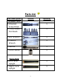
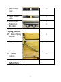
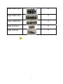
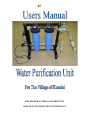
DEVELOPED AT OHIO UNIVERSITY BY BIOLOGICAL FILTRATION TECHNOLOGY Assembly and Installation Manual………………….. 3 Operation and Troubleshooting Manual…………… 26 Maintenance Manual………………………………… 31 2 ASSEMBLY AND INSTALLATION MANUAL This manual is meant to be a picture based guide on how to install and set up the water purification unit. Parts lists and step by step directions are given as well as piping and reservoir disinfecting instructions. 3 Parts List Part Description Included Tools A. Universal Screw Driver B. Phillip Heads/ Flat Heads Picture Quantity 1 1 C. 3/8” Wrench 1 D. Crescent Wrench 1 E. Ratchet 1 F. 13mm Socket 1 Frame Parts G.Left Frame Upright H. Right Frame Upright 1 1 4 I. Left Frame Foot J. Right Frame Foot K. U‐Channel L. Filter Cap Bracket Piping Sections M. Down Piping Section 1 1 1 1 1 N.Inlet Fixture 1 O. Outlet Fixture 1 Misc. Parts 5 P. Filter Housings 2 Q. 50 Micron Filter 2 R. 20 Micron Filter 2 S. Pipe Support Bracket 1 T. UV Chamber Mounts 2 U.Rubber Feet 4 Hardware 6 Type A Bolt Sets 8 Type B Bolt Sets 2 Type C Bolt Sets 2 Type D Screw 2 Type E Screw 2 7 Assembly Steps 1‐ Lay the four (4) frame pieces on the ground and match their corner colors as shown in Figure 1. Figure 1 8 2‐ Use Type A bolts and nuts to attach colored corners. Place bolts in side holes only, not bottom holes as shown in Figure 2. Follow the order of bolts, washers and nuts in Figure 3. Note: Hand tighten only. Figure 2 Figure 3 9 3‐ Use Type A bolts and nuts to attach U‐channel frame piece to the bottom hole of one of the frame sections that was just assembled as shown in Figure 4. Note: Hand tighten only. Figure 4 4‐ Use Type A bolts and nuts to attach the other side of the U‐channel frame piece to the bottom hole of the other frame section that was just assembled as shown in Figure 5. Note: Hand tighten only. Figure 5 10 5‐ Connect the down piping section shown to the 90 degree elbow on the orange side of the filter cap bracket as shown in Figure 6. Note: Be sure to Teflon tape the threaded end of the down piping section (highlighted by red box). Figure 6 6‐ Tighten the down piping section so that the black PVC pipe touches the steel elbow and so that the union is parallel to the orange corner as shown in Figure 7. Figure 7 11 7‐ Match the orange and pink colored surfaces on the filter cap bracket with the orange and pink colored surfaces of the frame as shown in Figure 8. Figure 8 12 8‐ Use two (2) Type A bolts and nuts to attach the filter cap bracket to the frame. Place the bolts in the side holes only on both the pink corner and the orange corner as shown in Figure 9. Note: Hand tighten only. Figure 9 9‐ Attach the pipe support bracket to the frame using Type B bolts as shown in Figure 10. Use flat head screw driver and crescent wrench to fully tighten. Follow order of bolts, washers, and spacers as shown in Figure 11 to correctly attach pipe support bracket to frame. Figure 10 13 Figure 11 10‐ Place the last two (2) Type A bolts in the bottom holes of the pink and orange corners as shown in Figure 12. Note: Use crescent wrench and 13mm socket to fully tighten all Type A bolts a quarter turn past snug. Figure 12 14 11‐ Attach the four (4) rubber feet to the bolt holes located at the ends of each frame feet as shown in Figure 13. Adjust the position of the bottom nut to desired height and tighten top nut using crescent wrench. Figure 13 15 12‐ Remove top half of UV Chamber Mounting Brackets to attach the mounting brackets to the frame feet using Type C bolts as shown in Figure 15. Use Phillips head screw driver and 3/8” wrench to tighten bolts. Follow order of bolts, washers, and nuts as shown in Figure 14 to correctly attach UV Chamber bracket to the frame. Figure 14 16 Figure 15 17 13‐ Position the UV chamber in its mounting brackets mating the union as shown in Figure 16. Tighten the union securely using a pipe wrench. Figure 16 14‐ Use Phillips head screw driver to tighten Type D screws to secure UV chamber as shown in Figure 17. Warning: Tighten to a quarter turn past snug, do not over tighten. Figure 17 18 15‐ Use Phillips head screw driver to attach UV ballast to the Left Frame Upright using Type E screws as shown in Figure 18. Figure 18 16‐ Place the filter elements inside the housings with the letters on top. 19 17‐ Match the letters on the filters with the corresponding letter on the filter cap bracket as shown in Figure 19. Figure 19 20 18‐ Screw filter housing into filter cap by hand, securing them tightly as shown in Figure 20. Figure 20 21 19‐ Use a pipe wrench to attach inlet fixture as shown in Figure 21. Note: Be sure to teflon tape the threaded end where the inlet fixture is being attached to. (highlighted by red box). Figure 21 22 20‐ Position the outlet fixture to the desired direction and then use a pipe wrench to attach outlet fixture to union located on the outlet of UV Chamber as shown in Figure 22. Figure 22 23 The water filtration system is intended to be installed inside of the pump house after the water pump. Alterations will have to be made to the current piping inside of the pump house in order to incorporate the filtration system. The adapters that are located on the inlet fixture and outlet fixture (circled in Figure 23) are male 1” BSPP thread and MUST be mated with female 1” BSPP connections. Figure 23 The power cord from the UV ballast is a standard U.S. three prong plug. An adapter and universal surge protector has been included, shown in Figure 24, can be found in a grey bag. The male side of the adapter will fit a standard Indian three prong plug and the female side will accept a standard U.S. three prong plug. 24 WARNING! It is necessary for the current water distribution system be cleaned thoroughly including all piping and water reservoirs past after the point of unit installation. This cleaning is necessary to ensure effective water purification and eliminate continued cross contamination. The plan below outlines the most effective method of cleaning the after purification unit installation: A bleaching process for cleaning is possible by using the purification unit for a filling point. Drain the water reservoir completely making sure to store some water for emergency use. Bleach may be filled into the empty filter housings while the filters are removed from the housings. Reattach them to the unit, turn on the UV bulb and pump the bleach water through the water distribution piping. A 10:1 water to bleach ratio is ideal for disinfection and this process of refilling with bleach should be repeated several times as to ensure adequate piping disinfection. Allow all water to drain from the reservoir. Manually enter any water storage reservoirs and thoroughly disinfect these container(s). Remove all sediment and debris from them and clean with a 10:1 water to bleach ratio solution or other non toxic disinfectant. The solution must be applied to the reservoir walls and allowed to sit for at least an hour to ensure disinfection and breakdown of the bleach. Rinse the water reservoir adequately with sterile water and allow to drain. With the purification unit powered on, pump purified water through the water piping and reservoir to rinse the distribution system. Rinse for at least 15 min and allow to drain completely through the reservoir. Refill the reservoir with purified water from the unit. If it is not possible to gain access the reservoir bleach flushing using the filter housings as outlined above should be used. While the purification system is being installed, water pipes and all debris and should be cleaned and removed. It is HIGHLY recommended to chemically clean as many components after the installation point of the water purification system as possible. It cannot be stressed enough the level of importance of cleaning all the water distribution components past the unit installation point. Water purification for the residents cannot be guaranteed if contamination is coming from a source after the water purification system. Please take all necessary steps to ensure proper effectiveness and operation of the purification unit. 25 OPERATION AND TROUBLESHOOTING MANUAL This manual is meant to be guide for the operation and control of the purification unit. Start up, running and shut down operational steps are given along with a trouble shooting guide. 26 Operation Procedure: Prepping the system 1. Make sure pump is OFF and ensure valve 2 (exit) is in the CLOSED position (Handle perpendicular to direction of flow) and entrance valve is turned towards the filter flow direction with arrow on the valve handle cover facing the proper flow direction. 2. Check the entire system for loose fittings and bolts. If any are found tighten or replace them before continuing. 3. Complete any necessary maintenance as outlined in the Maintenance Manual portion of this manual. 4. Plug in the UV bulb controller, ensuring that the surge protector is reset and all connections are secure. 5. Check the display on the controller and note the displayed days remaining to make sure it is not time to change the UV bulb. 6. Check for light emitting from the end of the UV chamber to make sure the bulb is powered. If no light is visible consult the troubleshooting guide to diagnose and resolve the problem. 7. WAIT 2 MINUTES for the UV bulb to warm up before pumping water through the purification unit. Failure to let the bulb warm up may decrease the effectiveness of unit. Running the system 1. Open valve 2 (exit) to pressurize the system in order to prime the pump for operation. 2. Turn on pump and begin the flow of water through the system. 3. Check all seals for leaks, if any are present turn off the pump immediately and consult the troubleshooting guide on the following 27 pages to diagnose and resolve the problem. DO NOT operate the system if any leaks are observed and immediately shut off the pump. 4. Operate the pump according to the normal filling schedule or until desired volume of water has been supplied to the reservoir. The pump will need to be operated for a longer time than before the purification unit’s installation to fill the reservoir. This is due to flow loss. 5. If at any time the system begins to leak or experience large vibrations turn off the pump and consult the troubleshooting guide. 6. Once all problems have been addressed water pumping can resume. Shutting down the system 1. Turn off pump. 2. Close valve 2 (Exit) by turning it to the perpendicular. 3. Disconnect the UV ballast and surge protector from the electrical source being careful of any bare connections. 4. Secure all electrical connections safely and away from any standing water. 28 Troubleshooting Guide: Symptom Pressure Increase Cause Dirty Filters Valve Closed Pipe Obstruction No flow UV Light Not On Pipe Leak Pump is Off Pressure Increase Ballast Unplugged Surge Protector Tripped System Grounds Bad Electrical Service Loose Pipes Bad Seal Filter Leak Loose Housing Bad Seal 29 Solution Remove and clean the particulate filters Make sure both valves are open Disassemble the piping and clear the obstruction Turn pump on See above Plug in Ballast Reset Surge Protector Check all grounds are secure Consult your electric provider Tighten the fitting by twisting clockwise Replace the Teflon tape seal on the threaded fitting. Twist the housing onto the cap by hand clockwise Reseat the o-ring properly (See maintenance manual) MAINTENANCE MANUAL This manual is meant to be a picture based guide on how to plan for and perform maintenance of the water purification unit. This manual is a supplement to the User’s Manual. Maintenance and inspection items are organized by their specific area and how often they should be performed. Weekly Maintenance Needs * Sediment filters * UV Bulb Sleeve Monthly Maintenance Needs * Checking of Frame * Detailed Filter Inspection * Flushing of UV chamber Yearly Maintenance Needs * Replacing the Filters * Detailed Inspection of Filter Housing and Replacement * Detailed Electrical Inspection * General Inspection 30 Weekly Maintenance & Inspections Sediment Filters Both filters are made to be washable, reusable and replicable. The supplied 50 (A) and 20 (B) micron filters can be removed, cleaned and put back into their housings as sediment build up occurs. Once the UV system is installed, the pressure gauge will be used to measure the pressure increase resulting from sediment build up on the filters. When a moderate increase in water pressure on the pressure gauge is observed or if it has been over 2 weeks since the last filter cleaning, the filters should be removed and cleaned following the below procedure. Steps to clean filters 1) 2) 3) 4) Make sure the pump and UV controller are both turned off. Close both the entrance and exit valves Place a drain pan underneath the exit plug of the UV chamber Using a wrench, loosen then drain bolt as show in the figure below. Press the pressure release buttons on top of the filter caps to assist draining. Allow to completely drain. 5) Using the supplied filter wrench, detach each filter and housing by turning clockwise. Remove the housings and drain them along with the drain pan as shown in the figure below. 31 6) Make sure the service hose is attached to the entrance valve. Remove the filters from the housings and place outside being careful to remove housing o-ring. 7) Check housing o-ring for and tears/nicks and replace as necessary. 8) With filters and service hose outside, turn entrance valve to the hose output setting as shown in the figure below. Turn on pump and begin careful spraying down of filters with service hose taking care to clean in between filter membranes. NOTE: Make sure not to spray the filters over powerfully as this could damage/tear the filter membrane material. 32 9) If the filters are excessively clogged and or dirty, clean them with a soft cloth and soap solution. Focus on removing built up sediment in between the membranes. NOTE: Never use bleach or petroleum based cleaners as this will damage the filters 10) Spray out the filter housings and rinse the filters again as necessary. 11) Place the cleaned filter back into the matching housing. Apply SILICON BASED LUCRICANT ONLY onto the filter o-rings and threads. NEVER USE PETROLIUM BASED LUBCICANT OR SEALANT. 12) Hand tighten the filters and housings back into place being careful to seat the housing o-ring properly. DO NOT USE THE FILTER WRENCH TO TIGHTEN. 33 UV Bulb Sleeve Keeping the quartz glass sleeve in the UV chamber clean is important for maintaining sterilization efficiency. Rust, sediment and mineral build up can coat the sleeve over time and reduce the amount of ultraviolet light that passes through it to sterilize the pumped water as it passes through the UV chamber. The quartz sleeve is designed to be easily accessed and cleaned on a regular basis. Steps to clean quartz sleeve 1) 2) 3) 4) Follow the draining procedure steps 1-4 outlined in the filter cleaning section. Remove the grounding wire and nut from the bottom of the UV controller cap Unhook the ring clamp from the top of the controller cap. Carefully pull the controller cap off and unplug the UV bulb from the cap. NOTE: NEVER TOUCH THE UV BULB OR THE BULB SLEEVE WITH BARE HANDS as the oils could damage and negatively affect the quality of the purification process. Use a soft cloth to handle the bulb and sleeve at all times. 5) Carefully remove the UV bulb with a soft dry cloth. Place on a soft cloth or towel. 6) Unscrew both of the UV chamber’s end caps. 7) Remove both of the quartz sleeve’s o-rings and check for tears/nicks and replace as necessary. 34 8) Taking caution not to drop the sleeve in the chamber, carefully pull out the sleeve with a soft damp cloth and wipe down. Use water or a mild cleaner if necessary to clean the sleeve. Rinse the sleeve after cleaning. 9) Using both hands and a soft cloth, carefully place the quartz sleeve back into the UV chamber using a finger the guide the sleeve into the chamber holes as shown below. 10) Insert the o-rings back onto the sleeve making sure both are flush against the chamber outlet holes as pictured below. 11) Screw both of the UV chamber end caps back on making sure the spring is seated properly on the rear end cap. 12) With a soft cloth, carefully re insert the UV bulb into the quartz sleeve. 13) Plug in the UV bulb into the controller cap. Be careful to align the 4 pins to the proper holes in the controller cap. 14) Carefully push on and align the controller cap to the upright position on the UV chamber. Make sure the grounding wire slot in the controller cap is placed over the grounding wire nut as shown below. 15) Push the ring clamp back on to lock the controller cap in place. 16) Screw the grounding wire and nut back on. 35 Monthly Maintenance & Inspections Checking of Frame Make sure that the bolts holding the frame are tightened and no parts are loose. Use a socket wrench to lighten frame bolts, clamps and nuts as necessary. Make sure that the plumbing is tight and undamaged. Use a pipe wrench to snug piping, couplings, gauges and valves as necessary. Some plumbing will have to be re sealed with plumbing tape or replaced over time. Carefully follow the installation instructions to remove and fix and replace faulty plumbing. Detailed Filter Inspection Follow steps 1-6 of the filter cleaning procedure. Carefully check both filters for holes and tears and by gently looking between the membranes. The filters will function properly with a minimal amount of damage present. If there are large holes or gaps present in the filters or if they are excessively clogged and cannot be cleaned then they should be replaced. Be careful to re install the proper 50 micron or 20 micron filter in its housing. The 20 micron filter is installed immediately before the UV chamber. Flushing of UV chamber Follow steps 1-8 of the UV quartz sleeve cleaning procedure. Next, complete the following steps to remove the UV chamber for cleaning and flushing. Steps to clean UV chamber 1) Follow steps 1-8 of the UV quartz sleeve cleaning procedure. 2) Loosen both of the piping couplings with a pipe wrench. 3) Unscrew the UV chamber clamps and remove the chamber. Make sure that all orings, caps and parts are removed and put in a safe place away from the chamber. 36 4) Take the service hose and UV chamber outside for cleaning. 5) Make sure the entrance T-valve is to the hose supply position. Turn on the pump and begin cleaning the entire chamber making sure to flush the inside of the chamber. 6) Turn off the pump and the let the chamber completely dry and hose empty. 7) Re install the chamber by screwing the clamps back on as well as the couplings. 8) Finish following procedures 9-16 of the UV quartz sleeve cleaning procedure to put the purification system back together. 37 Yearly Maintenance & Inspections Replacing the Filters Follow steps 1-6 of the filter cleaning procedure. The filters should be replaced at least once a year as they will begin to perform poorly over time. Be careful to re install the proper 50 micron or 20 micron filter in its housing. The 20 micron filter is installed immediately before the UV chamber. Detailed Inspection of Filter Housing and Replacement Over time the threads of the filter housings and caps will wear down due to normal usage. A detailed inspection of the threads for large nicks or cracks should be performed. If the purification system is leaking excessively at the filter housings they may need to be replaced. Follow the filter cleaning procedure steps and remove the housing(s). Following the installations manual, remove the filter bracket from the frame and associated piping. Remove the filter faulty cap(s) and housing(s) using the appropriate tools. Re install the new filter cap(s) onto the bracket making sure to lubricate the threads with a non-petroleum based lubricant such as silicon. Re install the connection plumbing to the bracket using piping tape. Install the filter(s) and filter housing(s) and check the system for leaks. Detailed Electrical Inspection Visually check all the wiring and connections of the UV controller and ballast system. Check the surge protector for damage or discoloration. If the UV controller is not working properly and not powering the bulb, follow the trouble shooting manual to determine the cause. Replace the entire UV controller and surge protector as necessary. Check the bulb for operation. The UV controller has a built in alarm system to notify when the bulb is not working. With the 38 purification system running, visually check the bulb operation by looking at the UC chamber plastic end cap to see if the light is on and shining brightly. The UV bulb should last for 9,000 hours or 3 years of usage at 6 hours/day. Follow the below procedure for bulb replacement Steps to replace UV Bulb 1) Follow steps 1-8 of the UV quartz sleeve cleaning procedure. 2) Replace the UV bulb by installing a new one onto the UV controller cap. 3) Finish following steps 9-16 of the UV quartz sleeve cleaning procedure. General Inspection Visually check all aspects of the purification system including the pressure gauge and relief valve. The pressure gauge should read near zero when the system is no turned on and no valves or plumbing should be leaking when the purification system is in operation. Replace excessively leaky or faulty parts as necessary. 39 MAINTENANCE SCHEDULE CHECKLIST 40