1
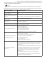
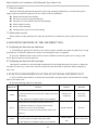
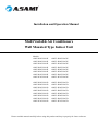
Installation and Operation Manual
Multi Variable Air Conditioners
Wall Mounted Type Indoor Unit
Models:
AMV-R22G/NaG-K
AMV-R28G/NaG-K
AMV-R36G/NaG-K
AMV-R45G/NaG-K
AMV-R50G/NaG-K
AMV-R56G/NaG-K
AMV-R63G/NaG-K
AMV-R71G/NaG-K
AMVL-R22G/NaG-K
AMVL-R28G/NaG-K
AMVL-R36G/NaG-K
AMVL-R45G/NaG-K
AMVL-R50G/NaG-K
AMVL-R56G/NaG-K
AMVL-R63G/NaG-K
AMVL-R71G/NaG-K
AMV-R22G/NaG-D
AMV-R28G/NaG-D
AMV-R36G/NaG-D
AMV-R45G/NaG-D
AMV-R50G/NaG-D
AMV-R56G/NaG-D
AMV-R63G/NaG-D
AMV-R71G/NaG-D
AMVL-R22G/NaG-D
AMVL-R28G/NaG-D
AMVL-R36G/NaG-D
AMVL-R45G/NaG-D
AMVL-R50G/NaG-D
AMVL-R56G/NaG-D
AMVL-R63G/NaG-D
AMVL-R71G/NaG-D
Please read this manual carefully before using this product and keep it properly for future reference.
USER NOTICES
◆◆ When operating, the total capacity of all indoor units should be not larger than that of that
of the outdoor unit. Otherwise, it will cause insufficient cooling (heating) performance.
◆◆ A breaker (or fuse) needs to be installed in every indoor unit, and the capacity should
comply with the indoor unit’s electrical parameter; all indoor units are required to be centralized
controlled by a main switch which can cut off the electric power supply in case of emergency. The
breaker (or fuse) on each indoor unit has the function of short circuit prevention and abnormal
overload avoiding and it should be energized in normal situation. The main switch is intended
to control the power supply of all the indoor units. Before cleaning and maintenance job being
carried out to the indoor units, it is very important to turn off the main power supply switch.
◆◆ In order to turn on the units successfully, the main power switch should be closed 8 hours
before the operation.
◆◆ After receiving the “turn off” signal, every indoor unit will continue to work for 20-70sec
to make use of the rest cool air or the rest heat air in the heat exchanger for preparing for the next
operation, which is certainly normal.
◆◆ When the selected operating mode of the indoor unit conflicts with the operating mode of
the outdoor unit, the malfunction indicating LED will blink 5s later on the indoor unit or remote
controller, then the indoor unit will stop. At this time, change the operation mode of the indoor
unit to the one that is compatible with the outdoor operating mode to make the operation normal.
The cooling mode can go with the dry mode, while the fan mode can go with any other mode.
◆◆ The appliance shall not be installed in the laundry.
◆◆ An all-pole disconnection switch having a contact separation of at least 3mm in all poles
should be connected in fixed wiring
◆◆ Main switch provided by the end user: the main switch handle should be black or gray,
and it can be locked in “OFF” position with padlock
◆◆ The main disconnection device should be described in this manual and the height should
be recommended at 0.6-1.7m. Over current protection is required (EN 60947-3, EN 60947-2).
◆◆ The outdoor environment temperature range for cooling is 18-43°C DB, while the outdoor
environment temperature range for heating (only for the heat pump type unit) is -16-15°C WB.
CONTENTS
1 SAFETY INFORMATION������������������������������������������������������������������������������������� 1
2 THE INSTALLATION OF WALL MOUNTED TYPE INDOOR UNIT�������������� 2
2.1 Schematic diagram of installation spaces���������������������������������������������������������� 2
2.2 The installation of the rear panel ���������������������������������������������������������������������� 2
2.3 Preparation of the piping hole��������������������������������������������������������������������������� 2
2.4 Installation of the drainage pipe������������������������������������������������������������������������ 3
2.5 Installation the connection pipes����������������������������������������������������������������������� 3
2.7 Installation of the indoor unit���������������������������������������������������������������������������� 4
3 STRUCTURES AND NAMES OF EVERY PART OF THE WALL MOUNTED 5
INDOOR UNIT��������������������������������������������������������������������������������������������������������� 5
4 WORKING TEMPERATURE RANGE����������������������������������������������������������������� 6
5 THE BEST USAGE METHOD������������������������������������������������������������������������������ 6
6 MAINTENANCE METHOD��������������������������������������������������������������������������������� 6
6.1 Cleaning panel��������������������������������������������������������������������������������������������������� 7
6.2 Cleaning the air filters���������������������������������������������������������������������������������������� 7
6.3 Check before the usage season�������������������������������������������������������������������������� 8
6.4 Check after the usage season����������������������������������������������������������������������������� 8
7 MALFUNCTION ANALYZING �������������������������������������������������������������������������� 9
7.1 Service center�������������������������������������������������������������������������������������������������� 10
7.2 After-sales service�������������������������������������������������������������������������������������������� 10
8 ADJUSTING METHOD OF THE AIR DIRECTION ���������������������������������������� 10
8.1 Adjusting air direction up and down���������������������������������������������������������������� 10
8.2 Adjusting air direction left and right���������������������������������������������������������������� 10
9 FUNCTION DESCRIPTION OF THE FUNCTIONAL DIP SWITCH S7��������� 10
Multi Variable Air Conditioners Wall Mounted Type Indoor Unit
1 SAFETY INFORMATION
A.Please read this manual carefully before use this unit, and operate it correctly according to the guide in
this manual.
B.Please take specially notice to the meaning of these two marks:
Warning!This mark means that it may cause casualty or badly hurt if the operation is incorrect.
Note!This mark means that it may cause casualty or property loss if the operation is incorrect.
Warning!
● For the usage safety of the air conditioner, the units should be earthed reliably, and the earth wire
should be connected to the special earth equipment in building. If there is no this kind of equipment, have the
units installed by specialized personnel. Do not connect the earth line with the gas pipe, water pipe, drainage
pipe or other places that specialized personnel considers unsafe.
● Air conditioner shall use special power supply circuit and switches for creepage protect and air with
enough capacity should be installed in the circuit.
● Ensure that the connecting of power cord is normal, otherwise, electric shock or fire may happened.
● Do not cut off the power supply to turn off the unit when it is running, otherwise the service life of
units may be shortened.
● Do not mangle wires or adopt wires that are not recommend, otherwise, electric shock or fire may
happen.
● Please don’t operate the unit by wet hands, or electric shock may happen.
● Don’t insert fingers or sticks or other similar things into the outlet vent, otherwise, damage may be
incurred.
● Cut down the main power switch immediately if a malfunction (such as the smell of burning etc.)
happens, and then contact the special appointed maintenance center. If the abnormal state persists, the unit
may be damaged or electric shock or fire may happen.
● Do not refit the air conditioner. Please contact the agent or professional personnel to repair or move the
air conditioner.
● Do not adopt the fuse with unsuitable capacity or adopt the iron thread instead of the fuse, otherwise a
malfunction or fire may happen.
● Do cut off the main power supply of the air conditioner if it would not be used for a long time period.
● Please turn off the main power of the unit before cleaning the air conditioner, otherwise electric shock
or harm may happen.
● Don’t blow the heater otherwise carbon monoxide may be produced because of uncompleted burning.
● Chemical sprayer should be placed at least 1m away from the unit, otherwise fire or explosion may be
caused.
● Do not let blockage happen in the inlet or outlet vent of the air conditioner, which would cause low
efficiency or shutdown.
● This appliance is not intended for use by persons (including children) with reduced physical, sensory
or mental capabilities, or lack of experience and knowledge, unless they have been given supervision or
instruction concerning use of the appliance by a person responsible for their safety.
● Children should be supervised to ensure that they do not play with the appliance.
1
Multi Variable Air Conditioners Wall Mounted Type Indoor Unit
2 THE INSTALLATION OF WALL MOUNTED TYPE INDOOR UNIT
2.1 Schematic diagram of installation spaces
ceiling
>150
ceiling
>150
>150
>3000
>2500
wall
unit:mm
ground
ground
Important Notice:
① .The unit shall be installed by the professional personnel according to this installation instruction to
ensure proper use.
② .Please contact the local ASAMI appointed service center before installation. Any malfunction caused
by the unit that is not installed by the ASAMI appointed service center would probably not be dealt with on time
because of the inconvenience of the business contact.
③ .It should be guided under the professional personnel when the air conditioner unit is moved to other
place.
2.2 The installation of the rear panel
Fig.1
A.Find the horizontal position by the seton method; since the drainage pipe is on the left side, it is
necessary to adjust the rear panel to make its left side a little bit lower.
B.Fix the rear panel on the wall by bolts.
C.After installing the rear panel, pull it by hands to check if it is secured enough. The hang panel should
support the weight of an adult (60KG), and the weight shared by every bolt should be fairly even.
D.The diameter showed in Fig.1 is 65mm.
2.3 Preparation of the piping hole
A.Make the piping hole (Φ 65mm) in the wall at a slight downward slant to the outdoor side. The center
of the hole should be determined referring to Fig.1
B.Insert the piping-hole sleeve into the hole to prevent the connected piping and wiring from being
damaged when passing through the hole.
2
Multi Variable Air Conditioners Wall Mounted Type Indoor Unit
2.4 Installation of the drainage pipe
A.For proper draining, the drain hose should be placed at a downward sloping.
B.Do not wrench or bend the drain hose or flood its end by water. (Fig.2)
C.Wrap the drain hose with heat resistant material.
Wrenched
Bent
Flooded
Fig.2
2.5 Installation the connection pipes
Connect the ends of the connection pipe with two leading pipes, and then tighten the joint nuts tightly.
Connect the connect pipe with the two relative leading pipe, tie the nut on tie –in of the connect pipe tightly.
2.6 Electrical wiring
Note: The power of every indoor unit should be unity power supply.
A.The power connection cord and the communication cord have been inserted on the mainboard through
the piping hole of the chassis and the bottom of the appliance upward.Please connect the power connection
cord with the breaker. If the power cord is not long enough,please prolong it with terminal block.
B.The shield twisted-pair in the 3 PIN neilsbed is the communication cord to another indoor unit or to
outdoor. Please connect it according to the cicuit diagram which is plastered on the control box.
If the next unit is Wall Mounted Type also, please insert the cord in the comm connecting board:
C.The twisted-pair in the
D.PIN neilsbed is the communication cord to the manual panal.
E. Reinstall the wiring cover on the original place and tighten the bolt;
F. Recover the surface panel.
Note!
① .The incorrect of wiring connecting would lead malfunction of some of the electric elements.
② .Make sure that the lead between the connect end and the clamp end has some need space after the
wire is fixed.
3
Multi Variable Air Conditioners Wall Mounted Type Indoor Unit
2.7 Installation of the indoor unit
A.When routing the piping and wiring from the left or right side of the indoor unit, it is necessary to cut
off the tailings of the pipe left on the holder of the unit. (Shown in Fig.5)
◆◆ Cut down tailings 1 when only the power cord is led.
◆◆ Cut down tailings 1,2 (or 1,2,3) when the connection cord and wire are led.
◆◆ The piping types ① , ② , ③ are recommended.
B.Let the tubing and cord pass though the piping hole after tied up (refer to Fig .5 (d)).
C.Hang the claw behind the indoor unit on the pothook on the wall panel, and move the unit left and right
to check if the body is firm.
D.Guarantee that the installation height of the indoor unit should be 2.5m above the floor.
①Right tubing
④Left tubing
②Right rear tubing
(a)
Low material 3
Low material 2
Low material 1
(c)
(b)
③Left rear tubing
Connection
pipe
Wrapping tape
Power
connection
cord
Control cord
Fig.5
4
Drain hose
(d)
Multi Variable Air Conditioners Wall Mounted Type Indoor Unit
3 STRUCTURES AND NAMES OF EVERY PART OF THE WALL MOUNTED
INDOOR UNIT
Wall mounted indoor unit
Air in
③
②
①
④
⑤
Air out
AMV(L)-R22G/NaG-K
AMV(L)-R36G/NaG-K
AMV(L)-R50G/NaG-K
AMV(L)-R63G/NaG-K
AMV(L)-R22G/NaG-D
AMV(L)-R36G/NaG-D
AMV(L)-R50G/NaG-D
AMV(L)-R63G/NaG-D
AMV(L)-R28G/NaG-K
AMV(L)-R45G/NaG-K
AMV(L)-R56G/NaG-K
AMV(L)-R71G/NaG-K
AMV(L)-R28G/NaG-D
AMV(L)-R45G/NaG-D
AMV(L)-R56G/NaG-D
AMV(L)-R71G/NaG-D
No.
Name
No.
Name
1
Surface panel
4
Guide louver
2
Filter
5
Connecting pipe
3
Wiring cover
Note!The appearances will be different by the different models of air conditioners.
5
Multi Variable Air Conditioners Wall Mounted Type Indoor Unit
4 WORKING TEMPERATURE RANGE
Indoor
Outdoor
Dry bulb temp°C
Wet bulb temp°C
Dry bulb temp°C
Wet bulb temp°C
Rated Cooling
27
19
35
24
Rated Heating
20
15
7
6
5 THE BEST USAGE METHOD
A.Adjust the set temperature properly in proper to prevent electricity wasting. It is better to control the
difference of the indoor and outdoor temperatures within 5°C.
B.The better effect will be maintained by adjusting the guide louver downward for heating and horizontal
for cooling.
C.When the air conditioner is running, don’t open windows or doors for long time, otherwise the
efficiency of unit will be lowered.
D.Prevent the cooled air blowing to body directly for long time and making indoor temperature too low,
for it is bad for health.
E. Do not pour water to unit or clean it by water, otherwise a malfunction or electric shock may happen.
F. Do not mangle the power cord and the communication cord. The damaged power cord and
communication cord can only be replaced by the specified ones.
G.This air conditioner allows voltage fluctuation within 220±10%V.
H.This air conditioner cannot be used for drying clothes and refrigerating food, etc..
6 MAINTENANCE METHOD
Warning!
A.Do turn off the unit and cut off the power when cleaning the air conditioner, otherwise electric shock
may happen.
B.Do not make the air conditioner wet or electric shock may be incurred; Ensure that the air conditioner
will not be cleaned by water rinsing under any circumstance.
C.Volatile liquid like thinner or gasoline would damage the appearance of the air conditioner. (Only soft
6
Multi Variable Air Conditioners Wall Mounted Type Indoor Unit
dry cloth and wet cloth moistened with neutral detergent could be used to clean the surface panel of the air
conditioner.)
6.1 Cleaning panel
Note!Do take down it before cleaning.
A.Pull along the direction of arrows to take down the panel.
B.Clean the panel
Clean it with a soft-hair brush, water and neutral cleaning fluid, and then dry it.
Caution!
Do not use water above 45°C to wash the panel to prevent decoloration or deformation.
C.Install the panel
As shown in Fig.II, install the stands of both ends of the panel into the slot and put the middle rotating
shaft into the groove, then place the panel and clasp back along the arrow direction.
Fig. I
Fig. II
6.2 Cleaning the air filters
Clean it once every 3 months; When the usage environment has lots of dust, it should be cleaned more
frequently.
A.Take down the air filter
As shown in Fig.III, open the surface panel by holding the both ends of groove along the arrow direction,
and then take the air filter out downward.
B.Clean the filter
Use cleaner or water to wash the filter; if the filter is too dirty ( like oil stain on it ), warm water ( lower
than 45°C) with neutral detergent can be used, then dry it in the shade.
Note!
Do not clean the filter by hot water higher than 45°C for preventing fade or deformation.
① ..
Do not burn it on fire or the filter would catches fire or deformation.
② ..
C.Install air filter
Install the air filter properly along the arrow direction, making the side marked “Front” facing yourself
and then place the panel back.
Fig. III
Fig. IV
7
Multi Variable Air Conditioners Wall Mounted Type Indoor Unit
6.3 Check before the usage season
A.Check if there is blockage in the inlet or outlet vent of the air conditioner.
B.Check if the earth wire is earthed reliably.
C.Check if the batteries in the wireless remote controller have been replaced.
D.Check if the air filter has been installed properly
In order to start up the air conditioner smoothly after it has been turned off for a long time period, energize
the unit 8 hours before turning it on.
6.4 Check after the usage season
A.Clean filter and body of air conditioner.
B.Cut off the main power supply of air conditioner.
8
Multi Variable Air Conditioners Wall Mounted Type Indoor Unit
7 MALFUNCTION ANALYZING
Warning!
Do not repair the air conditioner by yourself for the incorrect repair would lead to electric shock or fire.
Please contact the service center and have the unit repaired by the specialized personnel. Check the following
items before contacting the service center, as it could save your time and cost.
Malfunction Phenomena
Malfunction Analyzing
The air conditioner could not start up
The over load protection switch of the unit makes it run after 3 minutes
just after turned off
delay
Odor gave out when the unit just was
turned on
Slight bicker was heard when the
unit was running
Mist came from the air outlet vent
when cooling
Odors or cigarette smoke which has been absorbed in is discharged out.
This is the sound of the running refrigerant
Indoor air is cooled rapidly
Creak sound was heard when the unit
It is the sound emitted by the expansion of the panel and other parts
was running or after it was turned off
because of the temperature change.
Is the power supply cut off ?
Is the power supply connected ?
The air conditioner failed to run
Is the circuit protector started aside ?
Is the voltage too high or too low ?
If TIMER had been set on the wireless remote controller ?
Is the temperature set properly ?
Is the inlet, outlet vent of the outdoor unit blocked ?
The cooling (heating) effect of the
Is the air filter too dirty to cause blockage ?
air conditioner was not good
Are windows and doors closed ?
Is the air speed too low ?
Is there other heat source in the room ?
In the event that the battery is replaced but the wireless remote control
still malfunctions, then open the back cover and press ”ACL” button to
make it normal.
When the air conditioner is under abnormal interference or its functions
The wireless remote controller
cannot work
are changed too frequently, then the wireless remote controller would
works improperly. At this time, it is available to resume the normal
operation through de-energizing and then energizing the wireless
controller again.
Is the controller within the receiving area? or is there blockage?
Check if the voltages of batteries in the wireless remote controller are
sufficient; Otherwise change the batteries.
9
Multi Variable Air Conditioners Wall Mounted Type Indoor Unit
7.1 Service center
When the following phenomena appeared, please stop operating immediately, cut off the main power
supply of the unit and then contact the service center of the air conditioner.
◆◆ Harsh sound heard when running;
◆◆ The fuse or protector opened frequently;
◆◆ Substance or water pulled in the unit involuntarily;
◆◆ Water leakage in room;
◆◆ Power cord overheated;
◆◆ Abnormal odor is given out when running.
7.2 After-sales service
When quality or other problems arise upon the purchased air conditioner, please contact the local service
center.
8 ADJUSTING METHOD OF THE AIR DIRECTION
8.1 Adjusting air direction up and down
A.Controlling the guide louver motor by the wireless remote controller can make the guide louver swing
up and down, or makes the guide louver stop at a certain angle to have air supplied.
B.Press the SWING button on the wireless remote controller to make the guide louver swing up and
down; Repress again to stop the operation.
8.2 Adjusting air direction left and right
Moving the vertical louver left and right can adjust the left and right direction of air outlet, or adjust the
air outlet to reach every corner of the room by 3 different outlet directions to make the indoor temperature
more even.
9 FUNCTION DESCRIPTION OF THE FUNCTIONAL DIP SWITCH S7
A.The 3-bit DIP switch shall be set before the main board is energized and it will determine the running
status of the indoor unit.
B.See the following table for its functions:
DIP Switch
Function
DIP ON
DIP OFF
Standby after
Reset after
energizing
energizing
Wired controller
Receiver
Selection of memory mode:
1(S/R)
1. Election between reset mode and standby mode after
energizing;
2. This function is available without wired controller.
Selection between manual controller and receiver:
1. If Wired controller is selected, remote-control
2(L/I)
function of receiver will be shielded;
2. If receiver is selected, wired controller will be noneffective.
Setting of master and slave indoor units:
3(M/S)
1. For resolution of conflict among the modes;
2. This function is available without wired controller.
10
Master indoor
unit
Slave indoor unit
66129911521