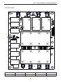
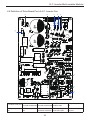
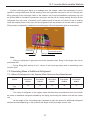
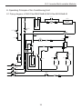
1
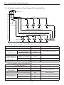
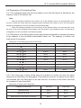
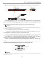
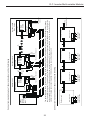
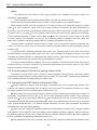
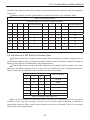
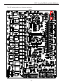
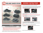
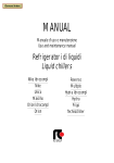
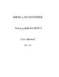
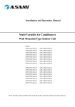
D.C. Inverter
Multi-variable Modular
Owner's Manual
Commercial Air Conditioners
AMV(L)-Pdm224W/NaB-M
AMV(L)-Pdm280W/NaB-M
AMV(L)-Pdm335W/NaB-M
AMV(L)-Pdm400W/NaB-M
AMV(L)-Pdm450W/NaB-M
AMV(L)-Pdm504W2/NaB-M
AMV(L)-Pdm1800W4/NaB-M
Thank you for choosing Commercial Air Conditioners ,please read this
owner’s manual carefully before operation and retain it for future reference.
User Notice
During use, the total capacity of indoor units in simultaneous service shall not exceed the
capacity of the outdoor unit; otherwise, the cooling (or heating) output of each indoor unit will be
low.
Install a circuit breaker (or fuse) to each indoor unit according to capacity of the unit and a
master circuit breaker to all indoor units. Each of the circuit breaker, which are normally on, is used
for short circuit and abnormal overload protection of indoor unit. The master circuit breaker is used
to supply or cut off power of all indoor units together. The general power supply of all indoor units
must be cut off before cleaning them.
For smooth start of air conditioner unit, the main power switch shall be put to “ON” position 8
hours before start.
The range of production working temperature
Cooling working range:
The single-module unit: Outdoor temperature10 ~48 ;
The multiple modularize parallel connection units: Outdoor temperature-5 ~48 ;
Heating working range: Outdoor temperature -18 ~27 ;
Upon receiving of STOP signal by each indoor unit, the fan of related indoor unit will continue
to work for 20~70 seconds for purpose of utilizing the remaining cold air or heats in heat exchanger
and also make preparations for next use. This is normal.
When the run mode selected for indoor unit conflicts against the run mode of outdoor unit,
the fault indicator on indoor unit will blink after 5 seconds or the operation of line controller display
will conflict, while the indoor unit will be stopped. To resume the normal status in this case, you
shall switch the run mode of indoor unit until it does not conflicts against the run mode of outdoor
unit. The cooling mode does not conflict against the dehumidify mode, nor fan mode against other
modes.
During installation, do not mix communication lines with power cables. Be sure to separate
them at minimum spacing over 20cm; otherwise it might result in communication problem.
It is not recommended to adopt the combination mode not specified by this manual.
1. Please read this manual carefully before use and operate correctly as instructed in the
manual.
2. You are specially warned to note the two symbols below.
Warning!: It means that incorrect operation may cause casualty or badly harm to people.
Caution!: It means incorrect operation may cause harm to people or damage to property.
Warning!
Please seek an authorized repair station for installation work. Improper installation might
cause water leakage, electric shock or fire.
Please install at a place strong enough to support the weight of air conditioner unit. If not, the
air conditioner unit might fall down and cause human injury or death.
To ensure proper drainage, the drainage pipe shall be correctly installed according to
installation instructions. Take proper measures for heat preservation to prevent condensing.
Improper installation of pipes might cause leakage and wet the articles in the room.
Do not use or store flammable, explosive, poisonous or other dangerous substances beside
the air conditioner.
In case of trouble (e.g. burnt smell), please immediately cut off the main power of air
conditioner unit.
Keep air flow to avoid shortage of oxygen in the room.
Never insert your finger or any objects into air outlet and inlet grill.
Please take constant care to check if the mounting rack is damaged after long use.
Never modify the air conditioner. Please contact the dealer or professional installation
workers for repair or relocation of the air conditioner.
Cautions!
Before installation, please check the power supply for compliance with the ratings on
nameplate. Check the power safety as well.
Before use, please check and confirm if the cables, drainage pipes and pipelines are
correctly connected, hence to eliminate the risk of water leakage, refrigerant leakage, electric shock
or fire.
Main power must be securely earthed to ensure effective grounding of air conditioner unit
and avoid the risk of electric shock. Please do not connect the earthing cable to coal gas pipe,
water pipe, lightning rod or telephone line.
Once started, the air conditioner shall not be stopped at least after 5 minutes or longer;
otherwise service life the unit will be affected.
Do not let the child to operate the air conditioner unit.
Do not operate the air conditioner unit with wet hands.
Please disconnect the main power before cleaning the air conditioner or replacing the air
filter.
Please disconnect the main power if to put the air conditioner unit out of use for a long
period.
Please do not expose the air conditioner unit directly under corrosive environment with water
or moisture.
Please do not foot on or place any goods on air conditioner unit.
After electrical installation, the air conditioner unit shall be energized for electrical leakage
test.
Contents
1. Selection of Installation Location and Precautions������������������������������������������������������� 1
1.1 Selection of Installation Location for Air Conditioner Unit�������������������������������������� 1
1.2 Cable Layout���������������������������������������������������������������������������������������������������������� 2
1.3 Grounding Requirement����������������������������������������������������������������������������������������� 6
1.4 Noise Control��������������������������������������������������������������������������������������������������������� 7
2. Installation of Outdoor Unit������������������������������������������������������������������������������������������� 8
2.1 Precautions on Installation of Outdoor Unit����������������������������������������������������������� 8
2.2 Outline Dimension of Outdoor Unit ����������������������������������������������������������������������� 9
2.3 Space dimension for installation of the unit is shown below.������������������������������� 10
2.4 Electrical Cable Connection��������������������������������������������������������������������������������� 14
3. Connection of Modular Outdoor Units������������������������������������������������������������������������ 15
3.1 The parallel connection at gas/ liquid side among modular outdoor units can be
performed by module connecting sub-assy, which can be selected from the following
table:�������������������������������������������������������������������������������������������������������������������������� 15
3.2 Piping beween module connecting sub-assies���������������������������������������������������� 15
3.3 Oil equalizing connection among modular outdor units��������������������������������������� 16
3.4 Skecth map of parallel connection among 3 units:���������������������������������������������� 16
3.5 Connecting piping among outdoor modules should be kept level to avoid oil
accumulated in a module.������������������������������������������������������������������������������������������ 16
3.6 The distance between module connecting sub-assies must be below 2m .�������� 16
4. Connection of Modular Outdoor Units������������������������������������������������������������������������ 17
4.1 Diverging mode of connection pipe between indoor and outdoor ����������������������� 17
4.2 Y-Type Refnet pipe����������������������������������������������������������������������������������������������� 17
4.3 Allowable Length and Drop Height of Connecting Pipe�������������������������������������� 18
4.4 Dimension of Connecting Pipe����������������������������������������������������������������������������� 19
4.5 Connection of Outlet Pipe for Indoor & Outdoor Unit������������������������������������������� 20
4.6 Connection of Refnet Pipe����������������������������������������������������������������������������������� 20
4.7 Installation of Protective Layer on Connection Pipe�������������������������������������������� 21
5. Communication Connection of Indoor and Outdoor units������������������������������������������ 22
5.1 Connection of Communication Line for Indoor Unit and Outdoor Unit����������������� 22
5.2 Communication Connection among Indoor Units ����������������������������������������������� 24
5.3 Instructions for DIP Switch at the Indoor Side����������������������������������������������������� 24
5.4 Instructions to DIP Switch at Outdoor Side���������������������������������������������������������� 25
6. Instruction to Connection Line and Definition of Port������������������������������������������������� 29
6.1 Eletric Wiring Design�������������������������������������������������������������������������������������������� 29
6.2 Definition of Mainboard(AP1)Port of Outdoor Unit����������������������������������������������� 30
6.3 Definition of Drive Board Port of Compressor������������������������������������������������������ 32
6.4 Filter plate������������������������������������������������������������������������������������������������������������ 33
6.5 Definition of Drive Board Port of D.C. Inverter Fan���������������������������������������������� 34
6.6 Definition of Drive Board Port of A.C. Inverter Fan ��������������������������������������������� 35
7. Filling of Refrigerant and Trial Run����������������������������������������������������������������������������� 36
7.1 Filling of Refrigerant��������������������������������������������������������������������������������������������� 36
7.2 Calculating Mass of Additional Refrigerant���������������������������������������������������������� 37
7.3 Inspection Items after Installation������������������������������������������������������������������������ 38
7.4 Test Run��������������������������������������������������������������������������������������������������������������� 38
8. Operating Principle of Air-Conditioning Unit��������������������������������������������������������������� 39
8.1 Piping diagram of AMV-Pdm224W/NaB-M,AMV-Pdm280W/NaB-M������������������� 39
8.2 Piping diagram of AMV-Pdm335W/NaB-M,AMV-Pdm400W/NaB-M,AMVPdm450W/NaB-M������������������������������������������������������������������������������������������������������ 40
8.3 Combination Sketch��������������������������������������������������������������������������������������������� 42
9. Maintenance Measures���������������������������������������������������������������������������������������������� 43
9.1 Check before usage season�������������������������������������������������������������������������������� 43
9.2 Maintenance after usage season������������������������������������������������������������������������� 43
9.3 Troubleshooting��������������������������������������������������������������������������������������������������� 44
9.4 Aftersales Service������������������������������������������������������������������������������������������������ 48
9.5 Rated working condition��������������������������������������������������������������������������������������� 48
9.6 The range of production working temperature����������������������������������������������������� 48
D.C. Inverter Multi-variable Modular
1. Selection of Installation Location and Precautions
1.1 Selection of Installation Location for Air Conditioner Unit
Caution!
The installation of air conditioner unit must be in accordance with national and local
safety codes.
Installation quality will directly affect the normal use of air conditioner unit. The user is
prohibited from installation by himself. Please contact your dealer after buying this machine.
Professional installation workers will provide installation and test services according to
installation manual.
Do not connect to power until all installation work is completed.
1.1.1 Selection of Installation Location for Indoor Unit
Avoid direct sunshine.
Ensure the hanger rod, ceiling and building structure have sufficient strength to support the
weight of air conditioner unit.
Drainage pipe is easy to connect out.
Air flow at inlet and outlet air is not blocked.
Indoor and outdoor connection pipes are easy to go outdoors.
Do not install at a place where flammable or explosive goods exist or flammable or explosive
gas might leak.
Do not install at a place subject to corrosive gas, severe dust, salty fog, smoke or heavy
moisture.
1.1.2 Select Installation Location of Outdoor Unit
Outdoor unit must be installed on a firm and solid support.
Outdoor unit shall be installed close to the indoor unit, hence to minimize the length and
bends of cooling pipe.
Avoid placing the outdoor unit under window or between two constructions, hence to prevent
normal operating noise from entering the room.
Air flow at inlet and outlet shall not be blocked.
Install at a well-ventilated place, so that the machine can absorb and discharge sufficient air.
Do not install at a place where flammable or explosive goods exist or a place subject to
severe dust, salty fog and polluted air.
Do not install induced draught pipe at the let and outlet of the outdoor unit. When the air
conditioner unit is generating heats indoors, the condensate water may flow from the base of
outdoor unit. When outdoor air is below 0 (32 ), the condensate water will be frozen. Take
care that the installation of outdoor unit shall not affect the heat radiation of the unit.
1
D.C. Inverter Multi-variable Modular
Caution!
Installation at following positions might cause trouble to the air conditioner unit. If unavoidable,
please contact ASAMI Authorized Service Center.
A place full of machine oil;
A region with saline-sodic soil near the sea;
A place with
sulphide gases (such as sulphur spring);
A place with high frequency facilities, such as radio
equipment, electric welder or medical equipment; An environment with special conditions.
1.2 Cable Layout
Carry out installation in accordance with the state line layout rules.
The power supply must be of rated voltage of the unit and special electrical line for airconditioning.
Please do not pull the power supply line violently.
All electrical installation shall be carried out by professional technicians in accordance with
the local laws and regulations
The diameter of flexible power cable must be large enough; damaged flexible power cable
and connection cable must be replaced by flexible cables of such special purpose.
Ensure safe grounding and the grounding wire shall be connected with the special grounding
equipment of the building and must be installed by professional technicians. In the fixed line there
must be an electrical leakage protection switch and an air switch with sufficient capacity (refer
to the following table). The air switch shall also have the magnetic tripping and thermal tripping
functions to achieve protection of both short-circuit and overload.
2
3
AMV(L)-Pdm1130W3/NaB-M
AMV(L)-Pdm1180W3/NaB-M
AMV(L)-Pdm1235W3/NaB-M
AMV(L)-Pdm1300W3/NaB-M
AMV(L)-Pdm1350W3/NaB-M
42
44
46
48
AMV(L)-Pdm900W2/NaB-M
32
AMV(L)-Pdm1065W3/NaB-M
AMV(L)-Pdm850W2/NaB-M
30
40
AMV(L)-Pdm785W2/NaB-M
28
38
AMV(L)-Pdm730W2/NaB-M
26
AMV(L)-Pdm950W3/NaB-M
AMV(L)-Pdm670W2/NaB-M
24
AMV(L)-Pdm1008W3/NaB-M
AMV(L)-Pdm615W2/NaB-M
22
36
AMV(L)-Pdm560W2/NaB-M
20
34
AMV(L)-Pdm450W/NaB-M
AMV(L)-Pdm400W/NaB-M
14
AMV(L)-Pdm504W2/NaB-M
AMV(L)-Pdm335W/NaB-M
12
18
AMV(L)-Pdm280W/NaB-M
16
224
AMV(L)-Pdm224W/NaB-M
8
10
450+450+450
400+450+450
335+450+450
280+450+450
280+400+450
280+335+450
280+280+450
280+280+400
450+450
400+450
335+450
280+450
280+400
280+335
280+280
224+280
450
400
335
280
Basic combination
models
Model
Rating Capacity
range(HP)
125
125
125
125
125
125
125
125
80
80
80
80
80
63
63
63
40
40
40
32
32
40+40+40
40+40+40
40+40+40
32+40+40
32+40+40
32+40+40
32+32+40
32+32+40
40+40
40+40
40+40
32+40
32+40
32+40
32+32
32+32
40
40
40
32
32
35.0
35.0
35.0
35.0
35.0
35.0
35.0
35.0
25.0
25.0
25.0
25.0
25.0
25.0
16.0
16.0
10.0
10.0
10.0
6.0
6.0
10.0+10.0+10.0
10.0+10.0+10.0
10.0+10.0+10.0
6.0+10.0+10.0
6.0+10.0+10.0
6.0+10.0+10.0
6.0+6.0+10.0
6.0+6.0+10.0
10.0+10.0
10.0+10.0
10.0+10.0
6.0+10.0
6.0+10.0
6.0+10.0
6.0+6.0
6.0+6.0
10.0
10.0
10.0
6.0
6.0
Air switch Each combinationed Diameter of total The wire diameter of each
capacity (A)
models opened
power wire
combinationed models
1.2.1 The modulized units combination open and selection table for power cable(the diameter default unit is mm2; the 5-core
wires are required):
D.C. Inverter Multi-variable Modular
AMV(L)-Pdm1405W4/NaB-M
AMV(L)-Pdm1456W4/NaB-M
AMV(L)-Pdm1512W4/NaB-M
AMV(L)-Pdm1570W4/NaB-M
AMV(L)-Pdm1650W4/NaB-M
AMV(L)-Pdm1700W4/NaB-M
AMV(L)-Pdm1750W4/NaB-M
AMV(L)-Pdm1800W4/NaB-M
50
52
54
56
58
60
62
64
450+450+450+450
400+450+450+450
335+450+450+450
280+450+450+450
280+400+450+450
280+335+450+450
280+280+450+450
280+280+400+450
Basic combination
models
160
160
160
160
160
160
160
160
40+40+40+40
40+40+40+40
40+40+40+40
32+40+40+40
32+40+40+40
32+40+40+40
32+32+40+40
32+32+40+40
50.0
50.0
50.0
50.0
50.0
50.0
50.0
35.0
10.0+10.0+10.0+10.0
10.0+10.0+10.0+10.0
10.0+10.0+10.0+10.0
6.0+10.0+10.0+10.0
6.0+10.0+10.0+10.0
6.0+10.0+10.0+10.0
6.0+6.0+10.0+10.0
6.0+6.0+10.0+10.0
Air switch Each combinationed Diameter of total The wire diameter of each
capacity (A)
models opened
power wire
combinationed models
① .The air switch shall also have the magnetic tripping and thermal tripping functions to achieve protection of both short-circuit and
overload,so should select breakers of “D”model
② .Carry out installation in accordance with the state line layout rules.
③ .The power supply must be of rated voltage of the unit and special electrical line for air-conditioning.
④ .Please do not pull the power supply line violently.
⑤ .All electrical installation shall be carried out by professional technicians in accordance with the local laws and regulations.
⑥ .The diameter of flexible power cable must be large enough; damaged flexible power cable and connection cable must be replaced by
flexible cables of such special purpose.
⑦ .Ensure safe grounding and the grounding wire shall be connected with the special grounding equipment of the building and must be
installed by professional technicians. In the fixed line there must be an electrical leakage protection switch and an air switch with sufficient
capacity (refer to the following table). The air switch shall also have the magnetic tripping and thermal tripping functions to achieve protection of
both short-circuit and overload.
⑧ .The specification of power cord mentioned hereby is defined as the required specification when wiring with BV single core cable (2 ~ 4
pieces) under the cover of PVC pipe, and environment temperature shall be at 40 ; Air switch shall be selected according to 40 temperature
condition, and shall in “D” type. if the installation condition on site changed, please consider the modification on the required specification of
Power cord and Air switch, according to the specification manual provided by manufactur
Note:
Model
Rating Capacity
range(HP)
D.C. Inverter Multi-variable Modular
4
D.C. Inverter Multi-variable Modular
1.2.2 Power cord Connect
Power Supply
Cabinet
QF
1
QFA
QFB
A
QFC
C
B
Unit A
Unit B
Unit C
1.2.3 Power supply specification of indoor unit
Tabel A: It is the capacity of breaker of general power supply of all indoor units in the same
system.
Total capacity of
indoor units
Capacity of
breaker (A)
Min. setion area of power
cord (mm2)
Min. setion area of grounding
wire (mm2)
Below10A
10
1.5
1.5
20~10A
20
4.0
4.0
32~20A
32
6.0
6.0
40~32A
40
10.0
10.0
50~40A
50
16.0
16.0
63~50A
63
35.0
16.0
80~63A
80
35.0
16.0
100~80A
100
50.0
25.0
125~100A
125
70.0
35.0
Note: Modify the actual parameters acoording to national law and rules.
5
D.C. Inverter Multi-variable Modular
Cpacity of single breaker for each indoor unit and specifiction of power cord.Pay attention
to that breaker of indoor unit, which is usually closed, is used for protection of short circuit and
abnormal overload.The terminal of each breaker should connect with a general power switch for
cutting off power supply of all indoor units.
Models of indoor unit
Capacity of
breaker (A)
Min. setion area of
grounding wire (mm2)
Min. setion area of power
cord (mm2)
Wall-mounted type
10
1.0
1.0
Duct type unit (heat pump
or cooling only)
10
1.0
1.0
Cassette type unit (heat
pump or cooling only)
10
1.0
1.0
One-way cassette type
unit
10
1.0
1.0
cabinet type unit
10
1.0
1.0
Breaker capacity of indoor unit with auxiliary electric heater should base on capacity of auxiliary
electric heater.The following unit models should be specially equipped with breakers.
Indoor unit models (with auxiliary electric
heater)
Capacity of
breaker (A)
Min. setion area of
grounding wire (mm2)
Min. sectional
area of
power cord
22,28,32,36 duct type unit
10
1.0
1.0
40,45,50 duct type unit
13
1.5
1.5
56,63,71,80 duct type unit
20
2.5
2.5
90,100,112,125,140 duct type unit
13
1.5
1.5
28,36,45,50 cassette type unit
10
1.0
1.0
56,63,71 cassette type unit
13
1.5
1.5
80,90,112,125 cassette type unit
13
1.5
1.5
22,25,28,32,36 ultra-thin duct type unit
10
1.0
1.0
40,45,50 ultra-thin duct type unit
13
1.5
1.5
56,63,71 ultra-thin duct type unit
16
2.5
2.5
1.3 Grounding Requirement
As air-conditioning unit is of Class 1 electrical appliance, reliable grounding measures must
be taken for it.
The double color (yellow and green) cable inside the unit is specially used for grounding, so it
shall not be used for other purposes nor can it be cut. Do not tighten with tapping screws; otherwise
it might cause risk of electric shock.
The ground resistance shall be in conformity with the requirements of state standard
GB17790.
6
D.C. Inverter Multi-variable Modular
The user power supply shall have reliable grounding terminal. It is prohibited to connect the
grounding wire to the following items:
Water Supply Pipe;
Gas Pipe;
Sewage Pipe;
Other positions that are considered to
be unreliable by professionals.
1.4 Noise Control
Install the air conditioner unit at a well-ventilated place; otherwise it might result in decreased
working capacity or higher noise.
Install the air conditioner unit securely on a base that can fully support its weight; otherwise
vibration and noise might be caused.
Install the outdoor unit so that the hot air or noise will not disturb your neighbors.
Do not place any obstacle close the outlet of outdoor unit; otherwise it might result in
decreased working capacity or higher noise.
If the air conditioner gives out abnormal noise during use, please immediately contact your
dealer.
7
D.C. Inverter Multi-variable Modular
2. Installation of Outdoor Unit
Note: Pictures for reference only, please refer to actual product. Unit: mm
2.1 Precautions on Installation of Outdoor Unit
To ensure the unit in proper function, selection of installation location must be in accordance
with following principles:
Outdoor unit shall be installed so that the air discharged by outdoor unit will not return and
that sufficient space for repair shall be provided around the machine.
Place of installation must be well ventilated so that the machine can absorb and discharge
sufficient air. Ensure the air inlet and outlet of the machine are not blocked. If blocked, please clear
off the obstacles blocking the air inlet or outlet.
Place of installation shall be strong enough to support the weight of outdoor unit, and it shall
be able to insulate noise and prevent vibration. Ensure that the wind and noise from the unit will not
affect your neighbors.
Outdoor unit must be lifted by using designated lifting hole. Take care to protect the unit
during lift. To avoid rusting, do not knock the metal parts.
Try best to avoid direct sunshine.
Place of installation must be able to drain the rainwater and defrosting water.
Place of installation must ensure the machine will not be buried under snow or subject to the
influence of rubbish or oil fog.
To meet the noise and vibration requirements, the outdoor unit shall be installed with rubber
damper or spring damper.
Installation dimension shall be in accordance with the installation requirements in this
manual. Outdoor unit must be securely fixed to the position.
The unit shall be installed by professional technicians.
8
D.C. Inverter Multi-variable Modular
2.2 Outline Dimension of Outdoor Unit
1670
Outline dimension and Installation holes of AMV-Pdm224W/NaB-M, AMV-Pdm280W/NaB-M
770
930
722~737
792
1670
Outline dimension and Installation holes of AMV(L)-Pdm335W/NaB-M, AMV(L)-Pdm400W/
NaB-M, AMV(L)-Pdm450W/NaB-M
1340
770
722~737
1203
9
D.C. Inverter Multi-variable Modular
2.3 Space dimension for installation of the unit is shown below.
2.3.1 Outdoor Unit Installation Space Dimension
>3000
>1000
>1000
>1000
(a)
c. 950~1350 Outdoor Unit Installation Space Dimension
>200
(b)
>1000
>200
Electrical Box
Outlet on this side.
>3000
Electrical Box
Outlet on this side.
Air Outlet
>200
>1200
>1000
>1200
>1000
>200
Air Outlet
>1000
Air Outlet
>3000
a. 224~450 Outdoor Unit Installation Space Dimension
b. 504~900 Outdoor Unit Installation Space Dimension
>1000
>1200
>1000
>200
>200
Electrical Box
Outlet on this side.
10
D.C. Inverter Multi-variable Modular
>200
>200
>200
>1000
Air Outlet
>3000
d. 1405~1800 Outdoor Unit Installation Space Dimension
>1000
>1000
>1200
>200
>200
>200
Electrical Box
Outlet on this side.
If the unit is surrounded by walls, the above basic requirements for installation should be met.
For the state that front side and right/left side of the outdoor unit is open:
No limitation to the height of the wall
0
>100
>200
Keep crown wall (air damper and suchlike barrier), if there is, 3000mm above from the top of
unit. Keep it 1500mm above from the top of the unit whose front, rear, left and right side are in the
open air. If not, a piece of return duct should be connected for smooth ventilation.
11
D.C. Inverter Multi-variable Modular
2.3.2 Installation space for multiple outdoor units
Keep top of units open, without air damper suchlike for smooth ventilation.
For the state that front side and right/left side of the outdoor units are open:
Install the unit at the same directions:
No limitation to the
height of the wall
Back
Front
Back
Front
Max. 4 sets side by side
Install the units back to back:
No limitation to the
height of the wall
Back
Front
Back
Front
Max. 4 sets side by side
12
D.C. Inverter Multi-variable Modular
For the state that the units are surrounded by walls:
It is recommended to install the units at the same directions.
No limitation to the
height of the wall
Back
Front
Back
Front
Max. 4 sets side by side
2.3.3 In consideration of seasonal wind during installation of outdoor units
Correct
Correct
Incorrect
Protector
Fresh air inlet
One side (rear side)
Fresh air inlet
One side (rear side)
Fresh air inlet
One side (rear side)
Fresh air inlet
One side (rear side)
In this state, defrosting
time will be prolonged.
13
D.C. Inverter Multi-variable Modular
2.3.4 In consideration of snow during installation of outdoor units
It is required to equip protectors on air outlet and air inlet and a higher foundation base to
prevent snow from covering air inlet and outlet.
Correct
Incorrect
Protector of air inlet
(provided at field)
Protector of air inlet
(provided at field)
Seasonal wind
Seasonal wind
Height of base in consideration of snow
2.4 Electrical Cable Connection
Cautions:
Outdoor unit and indoor unit may be of unified power supply or separate power supply. But the
indoor units must be of unified power supply. Be sure install a circuit breaker that can cut off the
power of complete system.
2.4.1 Connection of power cord:
1) Cable passes through the rubber loop.
2) Connect power cord to terminals that marks “L1, L2, L3 and N” or “L,N,PE” and earth screw.
3) Tighten the cable by wire clamp.
2.4.2 Connection of Communication Line for Indoor Unit and Outdoor Unit
1) Open the electric box of outdoor unit.
2) Pass distribution line (communication line) through the hole on side plate and then through
the rubber ring of electrical box.
3) Insert the communication line into 4-pin terminal CN46 or CN28 on circuit board of outdoor
unit.
4) Fix the wiring (communication) properly. press wire clip respectively onto the cables tightly
5) Put back the junction cover plate and tighten the screws. Cover up the panel.
14
D.C. Inverter Multi-variable Modular
3. Connection of Modular Outdoor Units
Parallel connection of Modular Outdoor Units, the following 3 types of connecting procedure
should be followed:
Parallel connection at gas side among modular units.
Parallel connection at liquid side among modular units.
Parallel connection of oil equalizing among modular units.
3.1 The parallel connection at gas/ liquid side among modular outdoor units can
be performed by module connecting sub-assy, which can be selected from the
following table:
Model
Description
Sketch
ML01-Liquid pipe
Sub-assy corresponding
With modular outdoor units
ML01/A
ML01-Gas pipe
Modular units should be connected according to their total capacity by copper pipe with
corresponding diameter to connect with module connecting sub-assy, so the pipe may be cut during
welding of module connecting sub-assies, which is normal. Meanwhile, corresponding connection
pipe’s length should be designed by installation personnel according to actual condition.
If it is required to cut pipe, cut the pipe with cutter from the middle of different sizes of pipes and
then remove the burrs, as shown in the following figure.
Cut from the middle
3.2 Piping beween module connecting sub-assies
Dimension requirements of piping between outdoor unit and connecting sub-assy is the same
as that of piping of single module
Single module capacity C
C
280
Gas pipe (mm)
Liquid pipe (mm)
φ22.2
φ9.52
φ28.6
φ12.7
280
C
450
15
D.C. Inverter Multi-variable Modular
If outdoor units are double or more modules by parallel connetion, piping dimensions between
module connecting sub-assies ML01/A should be selected with the table below,Dimension of piping
between module connecting sub-assies is decided by total capacity of upstream modules.
Total capacity code of outdoor
units at upstream side C
C
280
Gas pipe(mm/Inch)
Liquid pipe(mm/Inch)
Φ22.2 ∕ 7/8
Φ9.52 ∕ 3/8
280
C
450
Φ28.6 ∕ 9/8
Φ12.7 ∕ 1/2
450
C
670
Φ28.6 ∕ 9/8
Φ15.9 ∕ 5/8
670
C
950
Φ34.9 ∕ 11/8
Φ19.05 ∕ 3/4
950
C
1350
Φ41.3 ∕ 13/8
Φ19.05 ∕ 3/4
1350
C
1600
Φ44.5 ∕ 15/8
Φ22.2 ∕ 7/8
C
Φ54.1 ∕ 17/8
Φ25.4 ∕ 1
1600
3.3 Oil equalizing connection among modular outdor units
If outdoor units are double or more modules by parallel connetion, they should be connected
with oil equalizing. Oil-equalizing pipes are connected by Φ9.52 copper pipes.For example, if 3
outdoor units are parallel connected, an oil-equilizing connecting tee joint withφ9.7 inner diameter
in oil equalizing pipe is adopted.
3.4 Skecth map of parallel connection among 3 units:
>200
>200
Oil equalizing pipe
Connecting piping of module
connecting sub-assy
ML01 Gas pipe
ML01 Liquid pipe
Piping between modular unit
and connecting sub-assy
3.5 Connecting piping among outdoor modules should be kept level to avoid oil
accumulated in a module.
3.6 The distance between module connecting sub-assies must be below 2m .
16
D.C. Inverter Multi-variable Modular
4. Connection of Modular Outdoor Units
4.1 Diverging mode of connection pipe between indoor and outdoor
There are several diverging modes of connection pipe between indoor and outdoor units as
following
4.1.1 Y tpe diverging mode
Outdoor unit
Y-Type Refnet pipe
Indoor unit
Wired controller
4.2 Y-Type Refnet pipe
Y-Type Refnet Pipe: FQ01A,FQ01B,FQ02,FQ03,FQ04
Y-type refnet pipe can be selected from following list::
Total capacity code of indoor
units at downstream side X
X
Y-type refnet pipe
200
Model
FQ01A/A
200
X
300
FQ01B/A
300
X
700
FQ02/A
700
X
1350
FQ03/A
X
FQ04/A
1350
If total capacity of downstream indoor units is higher than capacity of outdoor units, refnet’s
capacity is subject to that of outdoor unit.
For FQ04, the rate between two branches’s corresponding downstream capacity can not
exceed 3:1.
For example: If pipeline of downstream indoor units with totoal capacity code of 1000 should be
branched off,total capacity code of downstream indoor units at any one side can not be lower than
250 after branching.
17
D.C. Inverter Multi-variable Modular
4.3 Allowable Length and Drop Height of Connecting Pipe
L1
The 1st
branch section
L4
L3
L2
Indoor unit
L5
Equivalent length of farthest pipe: L
The equivalent length of the farthest pipe from the 1st branch: L
L6
L8
L7
Height difference
between indoor units: H
Height difference between indoor unit and outdoor unit: H
Outdoor unit
Indoor unit
The equivalent length is 0.5m for each Y-type branch pipe.
Units with capacity of 60kW or more (fitting pipe mode is as above)
Allowable Value
Fitting Pipe
500m
L1+L2+L3+L4+…+L8+a+b+…+i
Total length (actual length) of fitting pipe
Length of farthest
fitting pipe(m)
Actual length
150m
Equivalent length
175m
L1+L5+L6+L7+L7+ L8+i
length from the first branch to the furthest piping
40m
L5+L6+L7+L7+ L8+i
Height difference
between outdoor unit
and indoor unit
Outdoor unit at upper
50m
——
Outdoor unit at lower
40m
——
15m
——
Height difference between indoor units(m)
Units with capacity between 20kW and 60 kW
Allowable Value
Fitting Pipe
300m
L1+L2+L3+L4+L5+L6+a+b+…+i+j
Total length (actual length) of fitting pipe
Length of farthest
fitting pipe(m)
Actual length
100m
Equivalent length
125m
L1+L3+L4+L5+L6+j
length from the first branch to the furthest piping
40m
L3+L4+L5+L6+ j
Height difference
between outdoor unit
and indoor unit
Outdoor unit at upper
50m
——
Outdoor unit at lower
40m
——
15m
——
Height difference between indoor units(m)
18
D.C. Inverter Multi-variable Modular
4.4 Dimension of Connecting Pipe
4.4.1 The refrigerant pipe size from the outdoor unit to the first branch is decided by the
capacity code of the outdoor unit.
Note:
① .When the distance between the outdoor unit to the farthest indoor unit exceeds 90m, then
the size of both the liquid and gas refrigerant pipes between the outdoor unit to the first branch
should be enlarged by one level as listed in the following table.
② .When the distance between the first branch to the farthest indoor unit exceeds 40m, then
the size of the liquid refrigerant pipe between the first branch to the farthest indoor unit should be
enlarged by one level as listed in the following table.
4.4.2 Dimension of the fitting pipes (refnet pipe) between branches is selected according
to the capacity of the connected downstream indoor unit. The capacity of outdoor unit
shall prevail if exceeded.
Dimension of the fitting pipe between branches
Total Capacity of Indoor Units
C
Gas pipe (mm)
Liquid pipe(mm)
Φ12.7
Φ6.35
56
56
C
142
Φ15.9
Φ9.52
142
C
220
Φ19.05
Φ9.52
220
C
300
Φ22.2
Φ9.52
300
C
450
Φ28.6
Φ12.7
450
C
670
Φ28.6
Φ15.9
670
C
950
Φ34.9
Φ19.05
950
C
1350
Φ41.3
Φ19.05
1350
C
1600
Φ44.5
Φ22.2
1600
C
2100
Φ54.1
Φ25.4
4.4.3 The fitting pipe (indoor fitting pipe) from branch to indoor unit has the same
dimension as the indoor unit fitting pipe. (If the distance from the 1st branch to an indoor
unit exceeds 30m, the fitting pipe on air side from the 1st branch to this indoor unit shall
be increased of one dimension).
Dimension of Indoor Unit Fitting Pipe
Capacity of Indoor Unit
Gas Pipe
Liquid Pipe
Model 22,25,28
φ9.52
φ6.35
Model 36,40,45,50
φ12.7
φ6.35
Model 56,63,71,80,90,100,112,125,140
Φ15.9
φ9.52
19
D.C. Inverter Multi-variable Modular
4.5 Connection of Outlet Pipe for Indoor & Outdoor Unit
See below for the torque required to tighten the nuts.
Align the expansion end of copper pipe with the
center of threaded joint. Tighten the flaring nuts with
your hands.
Tighten the flaring nuts with torque wrench until
you hear a “click”.
Bend of fitting pipe shall not be too low;
otherwise the fitting pipe might crack. Please use
Spanner
pipe bender when bending the fitting pipe.
Use sponge to wrap the connecting pipe and
joints without heat preservation. Tie with plastic tapes.
Torque Sheet for Tightening Nuts.
Fitting Pipe for
Indoor unit
Flaring Nuts
Fitting Pipe
Torque Spanner
Cautions:
① .When connecting indoor unit and pipe, never pull the big and small joint of indoor unit with
force, so as to prevent the capillary tube or other tubes of indoor unit from cracking and causing
leakage.
② .Connecting pipe shall be supported by a rack without transmitting its weight to other units.
4.6 Connection of Refnet Pipe
4.6.1 Y-Type Refnet Pipe
Y-Type Refnet pipe
Outlet 1
To other manifold pipe
or indoor unit
Inlet
Outdoor Unit
Pipe for Site Use
Outlet 2
Pipe for Site Use
Y-type refnet pipe is equipped with auxiliary tubes to adjust the diameter of different pipes.
If the dimension of the pipe selected for site use is different from the dimension of refnet pipe joint,
use the pipe cutter to cut from the middle of the pipe with different dimensions, and deburr as well.
Please see below.
Cut from the middle
20
D.C. Inverter Multi-variable Modular
Y-type refnet pipe must be installed so that the branch is in vertical or horizontal direction.
Within±30℃
Within±30℃
Heat preservation to refnet pipe. For side of gas pipe, adopt the heat preservation materials
that can stand temperature at 120 or higher, but don’t adopt the foam with refnet pipe. For liquid
pipe, in order to prevent water leakage, connect the heat preservation foam material with refnet
pipe and field heat preservation material, and then cover the juncture between them.
Cautions:
① .For multi-split air conditioner system, each pipe shall be pasted with label to identify the
pipe for each system and avoid wrong connection.
② .At inlet side of refnet pipe, keep at least 500mm straight pipe.
③ .Add an oil-return elbow at gas pipe side every 6m of drop difference between indoor units.
4.7 Installation of Protective Layer on Connection Pipe
1) To avoid condensate dew or water leakage on connecting pipe, the air pipe and liquid pipe
must be wrapped with heat preservation material and adhesive pipe for insulation from the air.
2) For heat pump unit, liquid pipe should bear 70 or above, and gas pipe should bear 120 or
above. For cooling only unit,both liquid pipe and gas pipe should bear 70 or above.
Example: Polyethylene foam can bear120 above and foaming polyethylene can bear 100
above.
3) The joints on indoor unit and outdoor unit must be wrapped with heat preservation materials
and have no clearance against the wall surface of indoor unit and outdoor unit.
No Clearance
Caution:
When the pipe is properly protected, do not bend it to a very small angle; otherwise the pipe
might crack or broken.
21
D.C. Inverter Multi-variable Modular
4) Wrap the pipe with tapes.
Use the adhesive tape to wrap the connecting pipe and cable into one bundle. To prevent
condensate water from overflowing out of the drainpipe, the drainpipe shall be separated from
connecting pipe and cable.
Wrap the heat preservation tape so that each ring of tape shall press half of the previous
ring.
Fix the wrapped pipe onto the wall with pipe clamp.
Caution:
Do not wrap the protective tape too tightly, as this will decrease the heat insulation
performance. Ensure that the drain hose of condensate water is separated.
After completing the protection work and wrapping the pipe properly, close the wall holes with
sealing materials.
5) Support and protection of pipeline
Support the suspended pipelines and distance between supports shouldn’t exceed 1m.
Protect the pipes above 1m with buckle to avoid damage.
5. Communication Connection of Indoor and Outdoor units
5.1 Connection of Communication Line for Indoor Unit and Outdoor Unit
Open the electrical box of indoor unit and outdoor unit. Insert the distribution line
(communication line) into electrical box via cable hole. Be sure to connect the indoor unit and
outdoor unit in accordance with the wiring diagram labeled on the unit. (Refer to the electrical wiring
of indoor unit and outdoor unit). The specification of power cable shall be selected in reference to
the power capacity and installation environment of the unit. If no error, press wire clip respectively
onto the cables tightly and then reinstall the electrical box cover. Magnetic rings shall be installed
on two ends of the communication line.
22
L1 L2 L3 N
L1 L2 L3 N
Adaptor CN1
board
Communication
wire
To unit 1 No.1 indoor unit
Terminal Board
CN18
Outdoor unit 2
L1 L2 L3 N
To unit 2 No.1 indoor unit
Adaptor CN1
board
Main
board
Terminal Board
CN17
Electric box
Communication
wire
L1 L2 L3 N
Terminal Board
Adaptor CN1
board
Main
board
Electric box
Outdoor unit N
Max. 4 sets
To unit N No.1
indoor unit
23
Power supply
380V 3Ph~50Hz
Power supply
220V~50Hz
Terminal board
Terminal board
L1 L2 L3 N
Indoor unit A
Outdoor unit
Connect communication wire of indoors unit by the following
Power supply
220V~50Hz
Terminal board
Indoor unit B
Power supply
220V~50Hz
Terminal board
Indoor unit N
Wiring
(resistor matching)
The part with dotted line is for the on-site wiring of the customer. The power wire diameter and the other specific parameter please
see the installation manual. The mainboard of outdoor units include the module address and transfer address need to confirm at the
work site and dial-up. Each outdoor unit module can connect maximum 16 indoor units, yet need to confirm on the work site. Each
outdoor unit module can connect maximum 16 indoor units as one communication unit.
3Ph~380V
50Hz
QF
Power
supply
Main
board
Communication
wire
CN18
Outdoor unit 1
CN18
Electric box
Communication
wire
Connect communication wire of indoor and outdoor unit by the following
D.C. Inverter Multi-variable Modular
D.C. Inverter Multi-variable Modular
Notes:
① .The distribution line refers to the communication line installed for the last indoor unit
(resistance compatibility).
② .Communication lines among outdoor/indoor units are connected in series.
Please connect communication lines of indoor unit and outdoor unit as shown above.
Each module outdoor unit can connect up to 16 sets of indoor unit, when the quantity of indoor
units 16, can connect all indoor units to the same outdoor unit module, but also allow some of
the indoor units to connect with different outdoor modules. When the system contains the quantity
of indoor units is 16 and 32, can connect indoor units to the two or more outdoor unit modules;
If the connected quantity of indoor units is 32 and 48, can connect the indoor units to the three
or more outdoor unit modules; and so on. The different outdoor modules need DIP code and
distinction of address switching, please refer to "outdoor- DIP switch instruction."
Communication connection should follow 2 steps: one is connection between pinboard and
indoor unit and the other one is connection between modules.Refer to wiring diagram among
outdoor units.
1) Communication between pinboard and indoor unit: Directly insert 2-core and 3-pin wiring
(communication) connected with indoor unit into 3-pin neilsbed of pinboard (outdoor units are
conneted by communication in series) and the other end into 3-pin soket of the first indoor unit’s
mainboard (indoor units are conneted by communication in series).
2) Communication between modules: If the unit is modular, insert one end of 2-core 4-pin wiring
(communication) into 4-pin socket of one module’s mainboard and the other end of it into 4-pin
socket of another module’s pinboard.
5.2 Communication Connection among Indoor Units
Connection among indoor unit is shown as wiring diagram among indoor units and outdoor
units adopts communication in series.Insert the two ends of 2-core and 3-needle wiring separately
into 3-needle nelsbeds of mainboards of 2 indoor units.
5.3 Instructions for DIP Switch at the Indoor Side
Assign address of indoor units according to programming of air conditioning system. One
outdoor unit could be connected with 16 indoor unit in maximum.The address of indoor unit under
the same system can not be identical and numbers are 1~16.
When they are modules,according to planning ofair-conditioning system and number of
pinboards. If connected indoor units 16, one or more pinboards can be used.If 16 connected
indoor units 32, 2 or more can be used.If 32 connected indoor units 48, 3 or more can be used.
Pinboards should be distinguished by addresses codes. One pinboard can connect up to 16 indoor
units, whose addresses are 1-16, without repeat.Adresses of indoor units connected by different
pinboards may have the same address.
There are two 4-digit DIP switches adopted on main board of indoor unit to assign address
and capacity. The 4-digit DIP switch for setting indoor capacity (marked “capacity” below) has been
set before outgoing, but the other 4-digit DIP switch (marked “address” below) should be adjusted
before installation, for assigning address of indoor unit.
The mainboard of the wire controller has a 4-bit DIP controller to allocate the address of the
24
D.C. Inverter Multi-variable Modular
controller. The address of the wire controller must be identical with the address of the corresponding
indoor unit.
Address Setting of Indoor Unit and Wire Controller Are Shown in the Following Table:
Bits 1~4 for Address Setting
Corresponding Pins of the 8-Bit (4-Bit) DIP Switch
4
3
2
1
Allocated Address
4
3
2
1
Allocated Address
0
0
0
0
1
1
0
0
0
9
0
0
0
1
2
1
0
0
1
10
0
0
1
0
3
1
0
1
0
11
0
0
1
1
4
1
0
1
1
12
0
1
0
0
5
1
1
0
0
13
0
1
0
1
6
1
1
0
1
14
0
1
1
0
7
1
1
1
0
15
0
1
1
1
8
1
1
1
1
16
Note: The position “ON” means “0”.
5.4 Instructions to DIP Switch at Outdoor Side
Modular outdoor unit’ s codes include quantity code of connecting modules, address code of
each Module,capacity code of module and transit address code.The position of each DIP switch is
shown as the Outdoor Unit Mainboard’s Port Diagram below.
The 4-bit DIP switch on mainboard SW1 (Capacity) is for capacity code of module. The codes
have been set before outgoing of unit, so they can’t be modified by user or intallation personnel.
Refer to Instruction to Capacity Code of Module for code setting mehod.
DIP Switch SW1
Module capacity
4
3
2
1
0
0
0
0
0
0
1
1
28kW
0
1
0
1
33.5kW
0
1
1
1
40kW
1
0
0
0
45kW
0
0
1
50.4kW
1
22.4kW
Note: The position “ON” means “0”.
The 2-bit DIP switch on mainboard SW2 (Out-No.) is for quantity code of connecting
modules. There may be 4 modules at most can be set with codes according to quantity of
connecting modules. Refer tothe following table Instruction to Quantity Code of Connecting
Modules for code setting method:
25
D.C. Inverter Multi-variable Modular
DIP Switch SW2
2
1
Quantity of
modules
0
0
1
0
1
2
1
0
3
1
1
4
Note: The position “ON” means “0”.
The 2-bit DIP switch on mainboard SW3 (Address) is for addresses codes of modules. There
may be 4 modules at most can be set with codes. Refer to the following table Instruction to Adrress
Code of Module.Furthermore, address code of one and only one of the modules must be set to ON
positions (i.e.00). The unit can’t normally run if address codes of modules on line aren’t increased
by degrees.
DIP Switch SW3
Adress of module
2
1
0
0
1
0
1
2
1
0
3
1
1
4
Note: The position “ON” means “0”. please note to be
accordant with transit address of module
(E.g. Adress codes of two modules for a unit must be 0 and 1, not 0 and 2).
The 3-bit DIP switch on transit mainboard S2 is for transit address code of module. There
may be 4 transit addresses at most can be set with codes according to quantity of connecting
modules.In this unit, it must have the same address as those at Adress of module
DIP Switch S2
3
2
1
Transit address of
module
0
0
0
1
0
0
1
2
0
1
0
3
0
1
1
4
Note: The position “ON” means “0”. please note to be
accordant with adress of module
26
D.C. Inverter Multi-variable Modular
The DIP switch position on Outdoor mainboard
UP
DOWN
SW1
SW2
SW3
RIGHT
LEFT
27
D.C. Inverter Multi-variable Modular
The DIP switch position on transit mainboard
Transit address
DOWN
UP
RIGHT
LEFT
28
D.C. Inverter Multi-variable Modular
6. Instruction to Connection Line and Definition of Port
6.1 Eletric Wiring Design
See the figure below for more details about the units AMV(L)-Pdm224W/NaB-M,AMV(L)Pdm280W/NaB-M,AMV(L)-Pdm335W/NaB-M,AMV(L)-Pdm400W/NaB-M,AMV(L)-Pdm450W/
NaB-M, and see Section 1.2.1 for more details about other units.
Power supply
Power supply
Power supply
L1 L2 L3 N PE
L1 L2 L3 N PE
L1 L2 L3 N PE
QF A2
QF A1
L1 L2 L3 N
Terminal board
QF AN
L1 L2 L3 N
Terminal board
Outdoor unit 1
Adaptor
board
CN1
Main board
CN18
L1 L2 L3 N
Terminal board
Outdoor unit 2
Outdoor unit N
Main board Main board
CN17
Main board
CN18
Power supply
L
N
(N≤4)
CN17
Power supply
PE
QF B1
L
N
L
N
PE
QF Bn
L
N
Terminal
board
Terminal
board
Indoor unit 1
Indoor unit n
(n≤16)
29
Wining
(resistor matching)
30
7
6
5
4
3
2
1
57
56
8
55
9
54
10
53
51
11 12 13 14 15
52
50
48
16 17 18 19 20
49
21 22 23
47
46
24 25 26
45
27
44
28
29 30
31
32
33
37
36
35
34
38
39
40
41
42
43
D.C. Inverter Multi-variable Modular
6.2 Definition of Mainboard(AP1)Port of Outdoor Unit
D.C. Inverter Multi-variable Modular
1-transformer input
2-Electronic expansion
valve
3-Transformer output
4-Communication ports
for fan and Inverter
compressor
5-Not Used
6-Not Used
7- Communication port
of pinboard and other
modules
8-LED indicator for
module state
9-Low-pressure sensor
10-High-pressure sensor 11-Not Used
12-Not Used
13-Exhasut temp sensor 14-Exhasut temp sensor 15-Exhasut temp sensor 16-Not Used
17-compressor temp
sensor
18-compressor temp
sensor
19-compressor temp
sensor
20- a CPU board
21- Not Used
22-Not Used
23- Not Used
24- Outlet pipe temp
sensor
25- Middle tube temp
sensor
26- Inlet pipe temp
sensor
27-Outdoor ambient
temp sensor
28- Capacity code
(SW1)
29-Quantity code of
modules (SW2)
30-Module address code
31-Not Used
(SW3)
32- Not Used
33- Not Used
34- Not Used
35- Not Used
36- Key 3
37- Not Used
38-overcurrent
protection switch
39-Not Used
40-High-pressure
protection switch
41- Not Used
42- Not Used
43-Solenoid valve of
capillary
44- Not Used
45- AC contactor of
Standard compressor 1
46- AC contactor of
Standard compressor 2
47-Not Used
48- Not Used
49-Liquid by-pass valve
50- Not Used
51- Not Used
52- Not Used
53- C valve
54- A valve
55- Gas by-pass valve
56-4-way valve
57-power supply
31
D.C. Inverter Multi-variable Modular
6.3 Definition of Drive Board Port of Compressor
1
28
2
27
26
25
24
3
4
5
23
6
7
8
9
10
11
12
13
22
14
15
16
17 18
19
20
21
1-Not Used
2- to rectifier + X44
3- LED indicator for
module state
4-Not Used
5- reactor 2
6- reactor 1
7- to rectifier - X55
8- Power in L3
9- to rectifier ~ X11
10- Power in L2
11- to rectifier ~ X22
12- Power in L1
13- to rectifier ~ X33
14- Power in N
15- compressor Heater
16-Not Used
17- Not Used
18- Not Used
19- Communication port
with mainboard
20- Not Used
21- Not Used
22-Not Used
23- Not Used
24- Not Used
25- Adress code port
(Not Used)
26- W-phase port of
Compressor
27- Vphase port of
Compressor
28- Uphase port of
Compressor
32
D.C. Inverter Multi-variable Modular
6.4 Filter plate
9
8
7
6
1
2
3
4
1-GND
2-Power in N
3- Power in L3
4- Power in L2
6- Power out L1
7- Power out L2
8- Power out L3
9- Power out N
33
5
5- Power in L1
D.C. Inverter Multi-variable Modular
1
2
3
4
5
6
8
7
6.5 Definition of Drive Board Port of D.C. Inverter Fan
1- Communication port
with mainboard
2- Communication port
with mainboard
3- Communication port
with mainboard
4- DC fan feedback
5-LED indicator for
module state
6- Adress code port
7- U/V/W-phase port of
DC fan
8- Connecting live and
neutral line port
34
D.C. Inverter Multi-variable Modular
5
6
7
8
1
2
3
4
10
9
6.6 Definition of Drive Board Port of A.C. Inverter Fan
1- Adress code port
2- Communication 3- Communication 4- LED indicator for 5- U-phase port of
port with mainboard port with mainboard module state
fan
6- V-phase port of
fan
7- W-phase port of
fan
8-Fan overheat
9- Connecting
protection interface neutral line port
35
10- Connecting live
line port
D.C. Inverter Multi-variable Modular
7. Filling of Refrigerant and Trial Run
7.1 Filling of Refrigerant
1) Before shipped out from manufacturer, the outdoor unit has been filled with refrigerant.
Additional refrigerant may be filled when carrying out site connection of pipelines.
2) Check the liquid valve and the gas valve of the outdoor unit. The valves shall be completely
shut off.
3) Connect a vacuum pump to the liquid valve and the gas valve of the outdoor unit to remove
air from the inside of the indoor unit and the connecting pipe. Refer to the following figure:
Manometer
Manometer
"HI"Knob
"LO"Knob
Liquid valve
Vacuuming pump
Connection hose
Gas valve
Liquid/Gas pipe vacuuming
Manometer
Manometer
"HI"Knob
"LO"Knob
Oil equalizing
valve
Vacuuming pump
Oil equalizing
pipe
Connection hose
Oil equalizing valve
Oil equalizing pipe vacuuming
36
D.C. Inverter Multi-variable Modular
4) After confirming that there is no leakage from the system, when the compressor is not in
operation charge additional R410A working fluid with specified amount to the unit through the
filling opening of the liquid pipe valve of the outdoor unit.If required additional refrigerant can not
be quickly filled for increase of pressure in the pipe, set the unit at cooling startup and then fill the
refrigerant from gas valve of outdoor unit.If ambient temp is low,the unit cann’t be set to cooling
mode but heating mode.In this case, fill the refrigerant from low-pressure air suction side of system.
Filling nozzle is especially installed on connecting pipe of liquid-separating joint,as show below:
Liquid pipe
Oil equalizing valve
Gas pipe
Filling of refrigerant
Note:
① .Filling of refrigerant in gas pipe should be operated when filling in liduid pipe can not be
performed well.
② .During filling after startup of unit, valves of liquid and gas pipes and oil equalizing valve
must be open.
7.2 Calculating Mass of Additional Refrigerant
7.2.1 Mass of Refrigerant in the System When Delivered from Manufacturer
Models
AMVPdm224W/
NaB-M
AMVPdm280W/
NaB-M
AMVPdm335W/
NaB-M
AMVPdm400W/
NaB-M
AMVPdm450W/
NaB-M
Charge amount
(kg)
12
13
15
16
17
Note:
① .The mass of refrigerant in the system when delivered from manufacturer does not include
the mass of additional refrigerant needed by the piping connecting the outdoor unit and the indoor
unit.
② .As the length of the connecting pipe is decided on site, the amount of additional refrigerant
shall be decided depending on the size and the length of the liquid pipe used on site.
37
D.C. Inverter Multi-variable Modular
7.2.2 Method of Calculating Mass of Additional Refrigerant to Be Filled (Based on the
Liquid Pipe).
Mass of Additional Refrigerant to Be Filled =∑ Length of Liquid Pipe × Amount of Additional
Refrigerant to Be Filled Per Meter of Liquid Pipe
Amount of Additional Refrigerant to Be Filled Per Meter of Liquid Pipe(kg/m)
Φ22.2
Φ19.05
Φ15.9
Φ12.7
Φ9.52
Φ6.35
0.35
0.25
0.17
0.11
0.054
0.022
7.3 Inspection Items after Installation
Check Items
Problems Owing to Improper Installation
Is the installation reliable?
The unit may drop, vibrate or make noises
Has the gas leakage been checked?
May cause unsatisfactory cooling (heating)
effect
Is the thermal insulation of the unit sufficient?
May cause condensation and water
dropping
Is the drainage smooth?
May cause condensation and water
dropping
Does the power supply voltage accord with the
rated voltage specified on the nameplate?
The unit may bread down or the
components may be burned out
Are the lines and pipelines correctly installed?
The unit may bread down or the
components may be burned out
Has the unit been safely grounded?
Risk of electrical leakage
Are the models of lines in conformity with
requirements?
The unit may bread down or the
components may be burned out
Are there any obstacles near the air inlet and
outlet of the indoor and outdoor units?
May cause unsatisfactory cooling (heating)
effect
Have the length of refrigerating pipe and
refrigerant charge amount been recorded?
It is not easy to decide the charge amount
of refrigerant.
Check
7.4 Test Run
7.4.1 Inspection before Test Run
Check if the appearance of unit and the piping are damaged during shipment or handling
Check if the terminals of the electrical components in the unit are loose and if the phase
sequence is correct
Check if the rotating direction of the fan is correct
Check if all the valves in the inspections system are all opened.
7.4.2 Test Run
After the results of the above inspection items are all accepted, the test run shall be carried
out by qualified technicians.
Energize the unit and set the status of the wire controller or the remote controller as ON.
The outdoor fan and the compressor shall automatically start up within one minute.
In case there is abnormal noise after the compressor starts up, immediately shut down the
unit and carry out inspection.
38
D.C. Inverter Multi-variable Modular
8. Operating Principle of Air-Conditioning Unit
8.1 Piping diagram of AMV-Pdm224W/NaB-M,AMV-Pdm280W/NaB-M
(11)
(10)
(12)
(21)
(13)
(15)
(9)
(19)
(14)
(18)
(16)
(8)
(20)
(7)
(17)
(24)
(23)
(4)
(2)
(27)
(28)
(5)
(6)
(22)
(26)
(25)
(29)
39
(3)
(1)
D.C. Inverter Multi-variable Modular
8.2 Piping diagram of AMV-Pdm335W/NaB-M,AMV-Pdm400W/NaB-M,AMVPdm450W/NaB-M
(11)
(10)
(12)
(21)
(13)
(15)
(9)
(19)
(14)
(18)
(16)
(8)
(20)
(7)
(24)
(6)
(17)
(4)
(6)
(4)
(5)
(3)
(23)
(2)
(27)
(28)
(22)
(26)
(25)
(29)
40
(2)
(1)
D.C. Inverter Multi-variable Modular
NO.
Name
Major Function
1
Inverter compressor(INV)
According to the actual need, the inverter compressor can
adjust its revolution among 30rps~90rps.
2
Standard compressor(STD1/
STD2)
When the inverter compressor fails to meet the needs
of the system, the fixed-frequency compressor will start
together.
3
High pressure switch(for INV)
When the discharge pressure of the inverter compressor
exceeds the upper limit of the high pressure switch,
a feedback signal will be sent out to stop the unit
immediately so as to protect the compressor.
4
High pressure switch(for
STD1/ STD2)
When the discharge pressure of the fixed-frequency
compressor exceeds the upper limit of the high pressure
switch, a feedback signal will be sent out to stop the unit
immediately so as to protect the compressor.
Check valve(for INV)
It is used to prevent the high-pressure reverse gas going
into the inverter compressor at the moment that the
compressor stops so as to avoid abnormal startup next
time and other problems.
6
Check valve(for STD1/ STD2)
It is used to prevent the high-pressure reverse gas going
into the fixed-frequency compressor at the moment the
compressor stops so as to avoid abnormal startup next
time and other problems.
7
Oil separator
It is used to separate the gas and oil so as to guarantee
the reliability of the compressor.
8
Check valve
It is used to prevent the high-pressure reverse gas going
into the modules at the moment that the unit stops
5
9
Four way valve
It is used to change the status of the heat exchanger.
10
Heat exchanger
It is used to exchanger heat outdoor.
11
Check valve
It is used to reduce the pressure loss of the refrigerant
flow.
12
Electronic expansion valve
It is used to adjust the degree of superheat and then adjust
the refrigerant flow to ensure the reliability and sufficient
heat exchange of the system.
13
Receiver
It is used to store unused refrigerant to avoid abnormity.
14
Check valve (for cooling)
It is used under the cooling mode.
15
Solenoid valve (for heating)
It is used under the cooling mode.
16
Check valve
It is used under the cooling mode.
17
Filter-drier
It is used to absorb moisture in the system so as to
avoid “ice plug” or “copper plating” on the surface of the
compressor
18
High pressure sensor
It is used to detect the real-time high pressure for
protecting the compressor and other controls.
19
Low pressure sensor
It is used to detect the real-time low pressure for protecting
the compressor and other controls.
41
D.C. Inverter Multi-variable Modular
20
Solenoid valve (hot gas)
It is used to protect the system running under low pressure
or the compressor starting with pressure difference.
21
Solenoid valve (liquid bypass)
It is used to prevent the compressor running at high
temperature.
22
Accumulator
It is used to prevent the compressor running at high
humidity condition.
23
Solenoid valve(INV)
It is used to return the lubricant to the inverter compressor.
24
Solenoid valve(STD1/ STD2)
It is used to return the lubricant to the fixed-frequency
compressor.
25
Solenoid valve(Oil balance)
It is used to balance the lubricant among modules.
26
Servicing valve
It is where the low pressure can be measured and
refrigerant can be charged for after-sales maintenance.
27
Liquid pipe
It is the pipe to pass the refrigerant liquid of the system.
28
Gas pipe
It is the pipe to pass the refrigerant gas of the system.
29
Oil balance pipe
It is the pipe to balance the lubricant oil between modules.
8.3 Combination Sketch
Outdoor Unit
Cassette Indoor unit
Single Side Air
Supply Indoor Unit
Wall-Mounted
Indoor Unit
Ducted Indoor Unit
(Rectangular Air Outlet)
System enables total capacitance of indoor units around 50-135% of rated capacitance of
outdoor unit.
D.C. Inverter Multi-variable Modular Air-Conditioning Unit consists of one or two or three or
four modular outdoor units and up to 64 indoor units.The indoor unit can be of cassette type, wallmounted type, ducted type and low hydrostatic pressure ultra-thin type, etc. The wall-mounted
type indoor units are controlled by remote controller; the ducted indoor unit and the low hydrostatic
pressure ultra-thin indoor units are controlled by remote controller and wired controller. For the
cassette indoor unit and one way air supply cassette indoor unit, remote controller or wire controller
can be freely chosen. When any indoor unit receives an operation order, the outdoor unit shall run
according to capacity requirements; the outdoor unit won’t stop until all indoor units stop operating.
42
D.C. Inverter Multi-variable Modular
9. Maintenance Measures
Warning!
Do stop the unit and turn off main power of the unit when cleaning the unit to avoid electric
shock .
Don’t make the unit wet to avoid electric shock.. Never clean the unit with water.
Caution!
Volatility liquid such as thinner or gasoline will damage appearance of unit, so only use soft
dry cloth and wet cloth with neutral detergent to clean shell of the unit.
Don’t clean the unit with hot water above 45 to prevent fade and deformation.
Never parch the air filter of indoor unit on fire to prevent fire or deformation.
9.1 Check before usage season
Check if there is obstruction in air outlet or inlet of indoor or outdoor unit.
Check if earth wire is earthed reliably
Check if batteries of remote controller have been replaced.
Check if air filter has been properly installed.
Check if installation of outdoor unit is firm. If there is any abnormal, please contact our
service center.
When restarting unit after long-time stop, in order to make startup of unit right ,main power
switch should be turned to “ON” state 8 hours before operating the unit.
9.2 Maintenance after usage season
Clean filter and body of both indoor and outdoor unit.
Cut off main power of air conditioning unit.
Clear dust and useless things in outdoor unit.
If outdoor unit is rusting, cover oil paint on it to prevent its expanding.
About maintenance method for indoor units, please refer to Instruction attached with
indoor unit.
43
D.C. Inverter Multi-variable Modular
9.3 Troubleshooting
Main control display for outdoor unit
Errors
LED1 LED2 LED3 LED4 LED5 LED6
Normal operation
○
●
Capacity of wrong
code dial
○
●
High-pressure
protection of
compressor
Low-pressure
protection of
compressor
Exhaust temp
protection of
compressor
Fixed Speed
Compressor
Overload
Protection
Lack of refrigerant
protection
●
●
●
●
●
○
Adapter
display
Digital
Tube
○
ON
●
○
-
●
●
○
●
●
●
●
●
○
Drive board for
compressor
LED1
(red)
Drive board
for Fan
LED2
LED3
(yellow) (green)
LED1(red)
Times of
continuous
flash
frequently
●
●
1
-
-
-
-
E1
-
-
-
-
○
E3
-
-
-
-
●
○
E4
-
-
-
-
●
○
E5
-
-
-
○
E3
-
-
-
○
-
-
-
-
○
E5
●
○
○
●
○
Communication
faults between
slave module and
the master (slave
module display)
●
Communication
error from inverter
drive to master
control
●
●
●
Super-high temp
of fin
○
○
○
○
E5
○
○
E5
○
○
○
E5
○
●
○
E5
○
○
E5
○
○
E5
●
-
○
○
E5
●
-
○
E5
Abnormality of fin
sensor
○
Current detection
or circuit error of
current sensor
○
○
Locked rotor
○
Current protection
of compressor
○
Super-high voltage
of DC input
○
Ultra-low voltage
of DC input
○
Abnormal IPM
○
●
○
○
○
○
○
44
-
-
-
-
-
○
-
-
-
●
-
D.C. Inverter Multi-variable Modular
Main control display for outdoor unit
Adapter
display
LED1 LED2 LED3 LED4 LED5 LED6
Digital
Tube
Errors
desynchronizing of
motor
●
●
○
Overspeed
●
○
○
●
○
Less phase, detune
●
●
Drive board for
compressor
LED1
(red)
LED2
LED3
(yellow) (green)
○
E5
○
○
E5
○
○
E5
○
●
○
Drive board
for Fan
LED1(red)
Times of
continuous
flash
frequently
-
○
-
Temp drift
protection
○
●
○
○
E5
○
AC contactor
protection
●
●
○
○
E5
●
○
-
○
○
○
E5
○
○
-
○
○
E5
●
○
E5
○
○
E5
Sensor connection
protection
Protection of
ambient temp
sensor on drive
board
○
●
Startup failure
○
○
AC-current
protection (input
side)
●
○
○
-
●
○
○
-
●
-
Abnormal PFC
●
○
○
●
○
E5
Drive module reset
○
●
○
●
○
E5
Fixed Speed
Compressor with
Low Discharge
Temperature
○
○
●
○
E5
-
-
-
-
Fan Module
Protection
○
○
●
○
○
-
-
-
-
2
Abnormal drive
voltage of fan
●
○
●
○
○
-
-
-
-
4
○
●
○
○
-
-
-
-
3
●
●
○
○
-
-
-
-
6
○
●
○
-
-
-
-
5
●
●
○
E6
-
-
-
-
●
○
-
-
-
-
-
○
-
-
-
-
-
Abnormal drive
current of fan
Fan module overheat protection
Communcation
error between fan
drive board and
master control
Communcation
error between
indoor unit and
outdoor unit
Defrosting
(normal,not error)
(normal,not error)
○
○
45
D.C. Inverter Multi-variable Modular
Main control display for outdoor unit
Adapter
display
LED1 LED2 LED3 LED4 LED5 LED6
Digital
Tube
LED1
(red)
○
-
-
-
-
-
○
-
-
-
-
-
Errors
Drive board for
compressor
LED2
LED3
(yellow) (green)
Drive board
for Fan
LED1(red)
Times of
continuous
flash
frequently
Both oil (normal
action, non-failure)
○
Online Testing
●
○
●
●
●
●
○
F4
-
-
-
-
●
●
○
F5
-
-
-
-
●
○
F6
-
-
-
-
●
○
F7
-
-
-
-
●
○
F9
-
-
-
-
●
●
○
F8
-
-
-
-
○
●
○
F8
-
-
-
-
Outdoor ambient
temp sensor error
Error of temp
sensor of outdoor
coil inlet
Failure of outdoor
coil middle sensor
Error of temp
sensor of outdoor
coil outlet
Failure of variable
frequency exhaust
sensor
Failure of fixedfrequency 1
exhaust sensor
Failure of fixedfrequency 2
exhaust sensor
Failure of variable
frequency shell top
sensor
Failure of Fixedfrequency 1 shell
top sensor
Failure of Fixedfrequency 2 shell
top sensor
High-pressure
sensor error
Low-pressure
sensor error
Disaccord of
quantity of
modules and code
indicating
Stop of unit for
error of other
modules
Note:
●
●
●
○
●
○
○
F9
○
●
○
○
-
●
●
○
○
-
○
○
Fc
-
-
-
-
○
○
Fd
-
-
-
-
○
○
○
●
○
-
-
-
-
-
●
○
●
○
-
-
-
-
-
indicates flash of light; ● indicates light off; ○ indicates light bright.
Warning!
① .If there is abnormal situation (such odor etc), turn off the unit and main power supply
46
D.C. Inverter Multi-variable Modular
immediately, and then contact with our service center. If the unit is still running in despite of
malfunction, it may be damaged and cause electric shock or fire.
② .Don’t repair the unit yourself by reason that incorrect repair will cause electric shock or fire.
Please contact our service center and have the unit repaired by professional technician.
9.3.1 Check the following items before contacting for repair
Phenomenon
The unit doesn’t run
Reason
Treatment
Fuse broken or breaker trips
Replace fuse or connect breaker
Power outage
Restart the unit when electricity
resumes, then unit runs.
Doesn’t connect with power
Connect with power
Electricity insufficient at wireless
remote control
Replace new batteries
Wireless remote control out of control
Control should be conducted within 8m
range
Unit runs but stop
immediately
Abnormal cooling or
heating
Air intake or outlet vent of indoor or
outdoor unit blocked
Clear obstruction
Air intake or outlet vent of indoor or
outdoor unit blocked
Clear obstruction
Improper set at temperature
Adjust setting at wireless remote
control or wired control
Fan speed set too low
Adjust setting at wireless remote
control or wired control
Wind direction is not correct
Adjust setting at wireless remote
control or wired control
Doors or windows opened
Close them
Direct sun burn
Draw curtain or jalousie
Too many people in the room
Too many heat resources in the room
Reduce heat resources
Filter is blocked for dirt
Clear filter
Instruction
If problems’ reasons are still unclear after checking the above items, please contact our service
center and show phenomena and models.
47
D.C. Inverter Multi-variable Modular
9.3.2 Following circumstance are not malfunction
“Malfunction”
Reason
When unit is started immediately after it Overload protection switch make it
is just turned off
run after delay for 3 minutes
Unit doesn’t run
When power is turned on
Unit runs in waiting for about 1
minute
When cooling
Indoor high humidity air is cooled
rapidly
Slight cracking sound is heard when just
turned on
It is noise when electric explosive
valve initialization
There is consecutive sound when
cooling
That the sound for gas refrigerant
flowing in unit
There is sound when unit starts or stops
That the sound for gas refrigerant
flows or stops
Mist comes from the unit
Noise is emitted
There is slight and consecutive sound
when unit is running or after running
Cracking sound is heard when unit is
operation and after operation
That is the sound for operation of
drainage system
That is the frictional sound caused
by expansion of panel and other
parts
The unit blows out duct
When unit operates after no operating
for long time
Dust in indoor unit be blew out
The unit emits odor
When operating
The room odor absorbed by the unit
is blew again
9.4 Aftersales Service
In case the air-conditioning unit has any quality problem or you have any inquiry, please contact
the local aftersales service agency designated by ASAMI.
9.5 Rated working condition
Indoor side state
Dry bulb temp.
Outdoor side state
Wet bulb temp.
Dry bulb temp.
Wet bulb temp.
Rated cooling
27
19
35
24
Rated heating
20
15
7
6
Note:
① .The following listed cooling /heating capacity and noise is tested before outgoing;
② .The parameters below are tested under rated working condition. If there is any change to
them, please refer to the nameplate;
③ .The parameters of heating capacity of indoor unit for heat pump excluded that of auxiliary
electric heating power.
④ .The performance parameters below are tested according to standard GB/T18837—2002
9.6 The range of production working temperature
Cooling working range
Outdoor temperature10
Heating working range
Outdoor temperature -18
48
~48
~27
66129911516