1
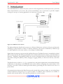
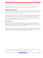
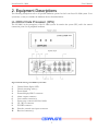
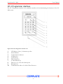
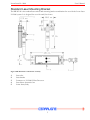
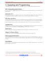
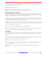
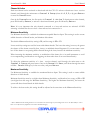
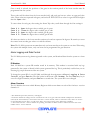
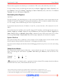
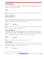
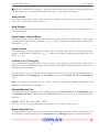
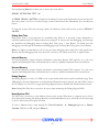
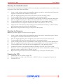
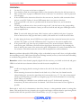
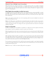
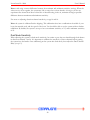
Cemar Electro Inc.
LL–2000 Loom Laser
User’s Manual
Loom Laser LL–2000
User’s Manual
Liability Disclaimer
Cemar Electro Inc. products are warranted in accordance with the terms of the applicable Cemar Electro
Inc. product specification. Product performance is affected by system configuration, software, the
application, customer data and operator control of the system, among other factors. While Cemar Electro
Inc. products are compatible with standards for which they are advertised, implementation of the product
by customers may vary.
Therefore, the suitability of the product for a specific application must be determined by the customer, and
is not warranted by Cemar Electro Inc.
This manual is as complete and factual as possible at the time of printing. Cemar Electro Inc. reserves the
right to change the functions, features, or specifications of its products at any time, without notification.
Please check the Cemar Electro Inc. website—www.cemarelectro.com—for product and documentation
update notifications. Should this documentation change, the newest version will always be available for
download at the Cemar Electro Inc. website.
This document has been prepared for use by Cemar Electro Inc. customers and employees. The information
contained herein is the copyrighted property of Cemar Electro Inc. and shall not be reproduced,
redistributed, or otherwise manipulated without the express written approval of Cemar Electro Inc.
CEMARLIGNE and LOOM LASER are registered trademarks of Cemar Electro Inc., U.S. and Foreign
patents pending.
Cemar Electro Inc.
528 Meloche
Dorval, Quebec
H9P 2T2
www.cemarelectro.com
[email protected]
ii
Loom Laser LL–2000
User’s Manual
Table of Contents
1. Introduction
Principle of Operation
Sensor/Receiver
2. Equipment Descriptions
LL-2000-2 Data Processor (CPU)
CP-3 Programmer Interface
Standard Laser Mounting Bracket
Precision Laser Mounting Bracket
Low Profile Receiver
Standard Receiver
Wide Angle Lens Receiver
3. Operating and Programming
CP-3 Operating Instructions
Starting the CP-3
Main Menu Operations
Language Select
System Setup
Channel 1 to Channel 4 Setup
Alarm Logging and Data Control
System Monitor
Installation and Debugging
CP-3 Menu Options
Basic Mode
Intermediate Mode
Advanced Mode
Saving Setup Changes
System Functions
System Setup
Alarm Reset Mode
Single and Multiple Loom Operation
Cut Off Delay
Output Polarity
Output On Time
Laser Control
Sensitivity Factor
iii
1
2
2
3
3
4
5
6
7
8
9
10
10
10
10
10
10
10
10
10
11
11
11
11
11
12
12
12
12
13
13
14
14
14
14
Loom Laser LL–2000
User’s Manual
Encoder Rotation
Start-up Delay
Dual Channel Delay and Dual Mode
Channel Setup
Channel # Active
Minimum Sensitivity
Maximum Sensitivity
Alarm Trip and Alarm Gate
Alarm Logging and Data Control
ID Number
Alarm Counters
Downloading Alarm Register
System Monitors
Channel Active Monitor
Alarm Gates Monitor
Receiver Status Monitor
Channel Ready Monitor
Alarm On Monitor
Alarm Counter
Shaft Encoder
Control Inputs – External Reset
Control Outpurs
Installation and Debugging
Extended Memory Test
Memory Retention Test
Debug Real Time
Internal Memory
External Memory
Debug Register
Reset System CPU
4. System Installation and Alignment
Laser and Receiver Installation
Mounting the Precision Laser Bracket(s)
Mounting the Standard Laser Bracket(s)
Mountin the Receivers
Preparing the CPU
Initialization
iv
15
15
15
15
16
16
16
17
18
18
18
19
19
19
20
20
20
20
21
21
21
21
21
21
21
22
22
22
22
22
23
23
23
24
24
24
25
Loom Laser LL–2000
User’s Manual
Wiring for Single and Multiple Loom Connections
Single Loom Operation
Multiple Loom Operation
Sensitivity Adjustment
Dual Mode Sensitivity
Appendix One: Installation Diagrams
Precision Bracket Installation
Standard Bracket Installation
Wide Angle Lens Receiver Installation
Low Profile Receiver Installation
Standard Receiver Installation
Appendix Two: External Connection Diagrams
Encoder, External Reset, and Alarm Output Connections
Output Relay Wiring for Multiple Loom Connection
External Display Connection
Data Communication Ports
Appendix Three: CP-3 Menu Structure
Basic Level Menu
Intermediate Level Menu
Advanced Level Menu
Contact Cemar Electro
Cemar Canada
Cemar U.S.A.
Cemar Europe
v
26
26
27
27
28
29
29
30
31
32
33
34
34
35
36
37
38
38
40
42
46
46
46
46
Loom Laser LL–2000
User’s Manual
1. Introduction
The CEMARLIGNE LL-2000 Loom Laser system is a fully-integrated laser and microprocessor system that
detects thread breaks on the loom. The system accommodates one to four lasers to provide complete
coverage for any type of weaving application, on looms up to 20 metres wide.
Figure 1: LL-2000 Loom Laser System
The high-performance thread-break sensors use solid state diode lasers and state-of-the-art optoelectronic
technology to detect threads as small as 30 microns (diameter). The system is unaffected by vibrations (up
to 14mm amplitude at the sensor surface), or by changes in ambient light.
Signals from the receiver(s) are processed by the Data Processor. The Data Processor is controlled by an Intel
80C31 microcontroller and field programmable devices which handle detection, display, and alarm indicator
functions. "Intelligent" programming enables the system to distinguish between actual broken threads and
false alarm causing dust particles, insects, hanging or sagging threads, or other noise that may cause false
alarms.
The Data Processor is built as a 1, 2, 3, or 4 channel unit, with special requirements accommodated through
modification or interchange of the EPROM based system software; redesigning the system circuitry is not
necessary. User data is stored in battery-protected memory, preventing the loss of data in the event of a
power failure.
All communications between the Data Processor and external devices-sensors, alarms, etc.-are isolated from
outside interference through the use of optical couplers. In addition, three connectors are available to
interface with external devices—PCs and other plant process control systems.
1
Loom Laser LL–2000
User’s Manual
The LL-2000 Data Processor is powered by a universal power supply, operating at 95 to 230 VAC, 50-60 Hz.
All functions and components of the LL–2000 system—laser emitters, receivers, the Data Processor, etc.—
are stable immediately upon power-up; there is no warm-up period necessary for these devices.
Principle of Operation
A narrow, visible beam is projected across the width of the loom from the laser emitter to the receiver. The
optical sensor in the receiver measures the total light energy arriving at its surface, converts the sensor input
to useable data, and transmits the data to the Data Processor.
The Data Processor interprets the data sent by the receiver(s). A valid signal—one that indicates a broken
thread—triggers an alarm, and can stop the loom so the thread can be repaired. Each alarm is registered in
non-volatile memory, and can be monitored by or uploaded to a control computer via the RS-232
communication port. All functions of the processor, including alarm functions, are controlled by the CP-3
hand held Programming Module, or by a PC loom computer.
Sensor/Receiver
The total area of the sensor is significantly larger than the cross section of the laser beam (visible as a red
dot), and is therefore able to receive signals from the emitter regardless of vibrations at the emitter—
vibrations which may cause the beam to stray off center. This remains true as long as the vibrations are not
significant enough to cause the beam to leave the sensor surface.*
Thread breaks are detected when small changes occur in the level of light received by the sensor. The Data
Processor interprets the data sent by the sensor to distinguish between actual broken threads and false alarms
caused, for example, by dust or insects passing between the emitter and the receiver.
* Note: The LR-2052 receiver unit is specially equipped with a wide-angle lens to assist the sensor by refocusing an off-center
beam to the center of the sensor. It can only assist as long as the projected beam strikes the lens.
2
Loom Laser LL–2000
User’s Manual
2. Equipment Descriptions
The following descriptions refer to all possible hardware options for the Loom Laser LL-2000 system. Your
system may or may not include the hardware devices described below.
LL-2000-2 Data Processor (CPU)
The LL-2000-2 is the centerpiece of the LL-2000 system. It contains the system CPU, and is the central
connection point for all peripheral hardware.
Figure 2 Detail drawing of LL-2000-2 system CPU
1.
2.
3.
4.
5.
6.
7.
8.
9.
10.
11.
Channel Status display LED
Chassis mounting screw(s)
Power Switch
External display DB 15 connector
Alarm outputs connector
Laser emitter connector(s)
Power entry connector and fuse holder
CP-3 RJ 12 connector
PC DB9 connector
Encoder, external reset inputs connector
Receiver connector(s)
3
Loom Laser LL–2000
User’s Manual
CP-3 Programmer interface
The CP-3 Programmer interface is the standard controller unit for administering the functions of the LL2000 system.
Figure 3 The CP-3 Programmer interface unit.
1.
2.
3.
4.
5.
6.
7.
8.
9.
10.
LCD display: 2 lines, 16 characters per line
Power indicator
Communication indicator
M (Menu) key
Up/Scroll key
Down/Scroll key
8 Enter/Return key
Data keys: 0-9, A-D, and decimal point
Backspace key
Communication cable to LL-2000-2 Data Processor
4
Loom Laser LL–2000
User’s Manual
Standard Laser Mounting Bracket
The BR 205-90 is the standard laser emitter and mounting bracket combination for use with the Loom Laser
LL-2000 system. It is designed for use with small, fast looms.
Figure 4 BR 205-90 Laser and Bracket assembly.
1.
2.
3.
4.
5.
Laser tube
Laser bracket
Connector to LL-2000-2 Data Processor
Laser driver electronics box
Loom frame/body
5
Loom Laser LL–2000
User’s Manual
Precision Laser Mounting Bracket
The LPB 2000-1/13 is designed for use with looms with widths larger than 12 metres. Equipped with
micrometric adjustors, the LPB 2000-1/13 easily adjusts to accommodate changes in the direction of the
laser emission caused by vibrations in the loom.
Figure 5 LPB 2000-1/13 Laser and Bracket assembly.
1.
2.
3.
4.
5.
Laser tube
Laser Bracket
Connector to Data Processor
Laser driver electronics box
Loom frame/body
6
Loom Laser LL–2000
User’s Manual
Low Profile Receiver
The LR 2050 is designed for small, fast looms, and for situations where space is an issue. The receiver's
extremely small profile (just 7.2 mm) allows installation almost anywhere. This unit is afforded its slim size
by removing the electronics box to a separate unit.
Figure 6 LR 2050 Small Flat (low profile) Receiver.
1.
2.
3.
4.
Receiver photocell
Loom frame
Laser receiver electronics box
Connector to Data Processor
7
Loom Laser LL–2000
User’s Manual
Standard Receiver
The LR 2051 is the standard receiver for use with the Loom Laser LL-2000 system. This receiver is
recommended for use with small to medium width looms (up to 10m/30 ft). The electronics box on this
receiver is integrated into the unit.
Figure 7 LR 2051 Receiver.
1.
2.
3.
4.
Receiver photocell
Receiver electronics box
Receiver cable
Connection to Data Processor
8
Loom Laser LL–2000
User’s Manual
Wide Angle Lens Receiver
The LR 2052 is a specially designed receiver, equipped with a wide-angle lens, for use with wide-width looms
(over 10m/30ft in width). The lens refocuses a slightly off-center beam to the center of the photocell sensor.
This helps to adjust for vibrations in the loom that may otherwise cause the beam to leave the sensor.
Figure 8 LR 2052 Receiver.
1.
2.
3.
4.
Receiver photocell with lens adapter
Receiver electronics box
Receiver cable
Connection to Data Processor
9
Loom Laser LL–2000
User’s Manual
3. Operating and Programming
All functions of the LL-2000 system are controllable using the CP-3 hand-held Programmer interface.
CP-3 Operating Instructions
The CP-3 connects to the Data Processor and receives its power through the RS-232 port on the back of the
Data Processor.
Starting the CP-3
When the Data Processor is turned on, the CP-3 power indicator will light. After a few seconds, the
Communication Indicator will flash once followed by a new message. Press Return to continue.*
Main Menu Operations
The CP-3 Main Menu gives the user access to numerous messages and functions. To access the main menu,
press M from any point in the menu system of the CP-3. After pressing M, you will see the language selection
options. From this screen, scroll up or down with the arrow keys ÙÚ to access other system menus.
Language Select
When the system starts up, or after pressing M, you will be prompted to key in 1, 2, 3, or 4 to select the
operating language—English, French, German, or Italian—of the CP-3.
System Set up
Use this menu to access global programmable features that apply to all channels (see pp 12-15).
Channel 1 to Channel 4 Set up
Use this menu to access programmable features specific to each channel (see pp 15-18).
Alarm Logging and Data Control
These data functions have no effect on system operation, they are used for system identification, logging and
transferring data to the CP-3 memory for data collection. Alarm logs can be reset from this menu (see pp
18-19).**
System Monitor
Use this menu to access information about channel status—Active, Ready, Alarm Gate, etc.—and to read
error messages (see pp 19-21).
* Note: references in this manual to pressing Return , are references to pressing the 8 key on the CP-3.
** Alarm Logging and Data Control can only be accessed when the system is running in Advanced Mode (see pp 11–12).
10
Loom Laser LL–2000
User’s Manual
Installation and Debugging
Use this menu to monitor system input, output, or internal registers. It is mainly for use with installation or
troubleshooting the main system board in the Data Processor (see pp 21-22).*
CP-3 Menu Options
The CP-3 has three different modes: Basic mode provides a read-only display; Intermediate mode lets the
user change settings on the system; and Advanced mode gives access to advanced features including
debugging, alarm register settings, and memory test options.
Basic Mode
Basic mode only allows reading of System Set up, Channel Set up, and System Monitors menus. While the
system is in basic mode, the user cannot change any settings. By default, the LL-2000 system starts in Basic
mode when powered-up. Upon starting the system in this mode, the user will see, after pressing the Return
key and scrolling down Ú one level, one of the following messages:
User Values, Default Values, or Temporary Values
This message depends on the state the system was last operating at when powered-down.
To confirm the system is in Basic Mode at start up, enter the System Set Up menu, and scroll up Ù until you
see the message: System is set to: (the mode).
Intermediate Mode
Intermediate mode offers the user the possibility of changing and saving system settings. To set the system
to Intermediate Mode, return to the main menu (by pressing M), scroll up Ù one level, key in C1 at the
System Setup menu, and press Return. This unlocks intermediate mode so the user can access
System and Channel Setup menus to change parameters for all functions. The changed values are
automatically saved as: Temporary Values.
These changes can also be saver permanently as User Values (see p 12).
To return the system to the basic mode, return to the main menu (by pressing M), scroll up Ù one level, key
in C0 at the System Setup menu and press Return.
Advanced Mode
Advanced mode gives the user complete access to all system settings. To set the system to Advanced Mode,
return to the main menu (by pressing M), scroll up Ù one level, key in C2 at the System Setup menu,
and press Return. Any changes made to the system are automatically saved as: Temporary Values.
* Installation and Debugging can only be accessed when the system is running in Advanced Mode.
11
Loom Laser LL–2000
User’s Manual
These changes can also be saver permanently as User Values (see below).
To return the system to the basic mode, return to the main menu (by pressing M), scroll up Ù one level, key
in C0 at the System Setup menu and press Return; to return to intermediate mode, enter C1 at the
System Setup menu and press Return.
Saving Set Up Changes*
To save the changes as User Values, scroll through the System Setup menu to:
TO SAVE SETUP TO
USERVAL PRESS A
Press A, and confirm by pressing Return. Changes will be confirmed with the message:
PRESENT SETUP IS
SAVED TO MEMORY
User values can be restored to default factory settings at any time. To do so, access the
System Setup menu, scroll to Reset to Default Values and press A. Confirm your selection
by pressing Return. The system will be restored to default settings. If you have previously saved User
Values settings, they can be reloaded by scrolling through the System Setup menu to Reset to
User Values, and pressing A.
To confirm system settings, scroll through the System Setup menu until you see one of three messages:
System is set to Default Values
System is set to User Values
System is set to Temporary Values
Reminder: Temporary Values are settings that have been changed but not saved as User Values.
To ensure changes are saved, please follow the steps outlined above for saving User Values.
System Functions
System Setup
Alarm Reset Mode
To access the alarm reset function, scroll through the System Setup menu to Alarm Reset Mode. To change
to mode 2, press the 2 key, then press Return.
* Note: Set Up changes can only be saved when the system is running in Intermediate or Advanced mode.
12
Loom Laser LL–2000
User’s Manual
The Alarm Reset Mode is used with an External Reset to reset the system after an alarm has been triggered.
After a reset, all system alarms will be cleared.
Note: the default setting is (mode) 1.
Mode 1 uses a momentary switch or contact relay to reset the system
Mode 2 uses a toggle or momentary switch or contact relay to reset the system.
Single and Multiple Loom Operation
The LL-2000 system can monitor one, two, three, or four looms simultaneously. To switch between single or
multiple loom monitoring, scroll through the System Setup menu to Single-Multiple Loom,
press 1 to enter multiple loom mode, or 0 to return to single loom mode.
In Mode 0, the system can only monitor one loom. When an alarm is detected while operating in mode 0,
all other monitoring channels will be disabled until the data processor receives the alarm reset signal (only
the first alarm will be displayed, and the loom will be stopped).
In Mode 1, the system can control two, three, or four looms. In this mode, any alarm, on any channel, will
be displayed in the system display. An alarm reset signal from any operating channel will reset all channels
that are in alarm (but will not stop all looms).
The default setting for Single and Multiple Loom Operation is Mode 0.
Note: When monitoring multiple looms, however, the time between event detection and alarm is increased.
It is therefore recommended that each LL-2000 system monitor only one loom.
Cut-off Delay
The cut-off delay is used to set the length of time-the delay-during which the data processor will wait before
an interrupted signal triggers an alarm. The delay can be set for any time interval between 0.5 and 10.0
seconds.
This is an advanced feature, and can only be accessed if the system is operating in the Advanced mode (see
above pages 11-12 ) for more information on changing operating levels.
Note: The cut-off delay cannot be set lower than 0.5 seconds.
To set the cut-off delay, scroll through the System Setup menu to Cut-Off Delay, key in the time
delay, and press Return.
Remember: to access the cut-off delay option you must be operating the system in advanced mode
(see p 12).
13
Loom Laser LL–2000
User’s Manual
Output Polarity
Using this option, an NC or NO pair of contacts are used to send the stop signal to the loom(s) when an
alarm is detected.
To set the Output Polarity, scroll through the System Setup menu to Output Polarity, and select
NC or NO.
Output On-Time
Output On-Time controls the Alarm Output Relay for the four alarm channels when an alarm is detected
on the system. It can be set from 0.0 seconds to 10.0 seconds. When set at 0.0 seconds, the Output
Relay will switch and remain latched until a Reset signal is received from the halted loom. This setting applies
to all four channels.
Note: the default setting is 0.0 seconds.
To set the Output On-Time, scroll through the System Setup menu to Output On-Time, key in an
Output On-Time setting, and press Return.
Laser Control
This feature turns lasers on or off. There are four modes:
Mode 0 - the operator has no control of the lasers: they all remain permanently on.
Mode 1 - with a particular channel activated or deactivated, the corresponding laser will be on or off.
Mode 2 - if there is an alarm on an active channel, the corresponding laser will be shut off. After a reset,
the laser will be reactivated.
Mode 3 - if there is an alarm on any active channel, all lasers will be turned off. After a reset, all lasers will
be reactivated.
To access laser control, scroll through the System Setup menu to Laser Control, key in 0, 1, 2,
or 3, to select the mode, and press Return.
Sensitivity Factor
The Sensitivity Factor determines how the system reacts to thread breaks. This is a global setting, and affects
all channels in the same way. It can be set to be more or less sensitive to thread speed and thickness.
There are three possible settings: 1 or 2 for fast-moving, medium-thickness threads; 3 for slow-moving, thin
threads
To access the Sensitivity Factor, scroll through the System Setup menu to Sensitiv. Factor, key
in 1, 2, or 3, and press Return.
Note: the default Sensitivity Factor is 3.
14
Loom Laser LL–2000
User’s Manual
Encoder Rotation
To tell the LL-2000 system which direction your loom Encoder* is rotating, scroll through the System
Setup menu to Encoder Rotation, select Left (CCW) or Right (CW), and press Return.
Start-Up Delay
The start-up delay is the time interval between loom start-up and when the LL-2000 starts detecting thread
breaks. This delay prevents premature false alarms caused by loom acceleration or hanging threads during
loom start-up. The delay can be set from 1.0 to 10.0 seconds. The default value is 1.0 second.
To access the Start-Up Delay settings, scroll through the System Setup menu to Start-Up Delay,
key in a value between 1.0 and 10.0 seconds, and press Return.
Note: It is extremely important the Start-Up Delay is set to a value of 1.0 or greater. Setting this delay
below one second will cause the system to malfunction.
Dual Channel Delay and Dual Mode
Dual Channel Delay is used with Dual Channel Mode. In Dual Mode, channels 3 and 4 are coupled to eliminate false alarms in special operation conditions—such as in extremely dusty areas where dust particles may
otherwise cause false alarms.
While operating in Dual Channel Mode on channels 3 and 4, the system will not trigger an alarm unless both
channels indicate a broken thread at the same moment. Ideally, for this system to work correctly, the channel
3 and 4 lasers and emitters should be placed in close proximity to each other.
The Dual Channel Delay can be set for 0.1 to 10.0 seconds. When set below 0.1, that is at 0.0, the system
is no longer operating in dual mode. By default, the LL-2000 does not operate in Dual Mode, and the Dual
Channel Delay is therefore set at 0.0.
To adjust the Dual Channel Delay settings, scroll through the System Setup menu to Dual Chan.
Delay, key in the delay time, and press Return.
To put the system into Dual Mode, enter a value greater than 0.0 (but not greater than 10.0) for Dual
Channel Delay.
Channel Setup
The LL-2000 controls up to four separate laser - receiver channels. Because each laser - receiver channel
operates in different places on the loom (or in some cases on different looms) each channel must be
separately configured; there are no global settings for the laser channels.
* The (loom shaft) encoder is a device installed on the loom; this setting is used to inform the LL-2000 system which direction
the encoder rotates.
15
Loom Laser LL–2000
User’s Manual
Channel # Active
Each laser channel can be activated or deactivated with the CP3.* To activate or deactivate a laser - receiver
channel, scroll through the main menu to Channel # Setup (where # is 1, 2, 3, or 4); press Return
to enter the Channel menu.
Once in the Channel menu, the first option is Channel # Active. To deactivate an active channel,
press 0 followed by Return; to activate a deactivated channel, press 1 followed by Return.
Note: It is very important that only channels connected to a laser and receiver are activated. AVOID
activating a channel that does not have a laser and receiver connected to it.
Minimum Sensitivity
Use Minimum Sensitivity to establish the minimum acceptable Receiver Input. This setting is used to ensure
reliable detection of thread breaks, and eliminate false alarms.
The default Minimum Sensitivity setting is 01, and the range is 00 to 19.
Lower sensitivity settings are used for looms with thinner threads. The lower the setting, however, the greater
the chance of false alarms caused by dust, insects, or multibrain thread fragments. If you encounter a number of false alarms or are passing thicker threads through the loom, increase the minimum sensitivity.
When increasing the minimum sensitivity to troubleshoot false alarms, do so in small increments to avoid
over-compensating (and therefore not triggering an alarm when there is an actual thread break).
To adjust the minimum sensitivity of a laser - receiver channel, scroll through the main menu to the
Channel # Setup, and press return. Once in the Channel # Menu, scroll down through the menu
to Min. Sensitivity, key in the new value, and press Return.
Maximum Sensitivity
Use Maximum Sensitivity to establish the maximum Receiver Input. This setting is used to ensure reliable
detection of thick threads.
Maximum Sensitivity must be set higher than Minimum Sensitivity, and therefore has a range of 01 to 20
(one higher than the range for Minimum Sensitivity). The higher the Maximum Sensitivity, the better the
system will detect thread breaks in thick threads.
To achieve the best results, this setting should be adjusted at the same time as the Minimum Sensitivity.
* This is different from turning the laser on or off. See Laser Control (p 14) for turning lasers on or off. The ability to turn a
laser on or off, however, depends on its active channel setting(s).
16
Loom Laser LL–2000
User’s Manual
To adjust the maximum sensitivity of a laser - receiver channel, scroll through the main menu to Channel
# Setup, and press Return. Once in the Channel # Menu, scroll through the menu to Max.
Sensitivity, key in the new value, and press Return.
To detect the widest range of thread sizes on any given laser - receiver channel, set the Maximum Sensitivity
to the highest value, and the Minimum Sensitivity to the lowest value.
Remember: this can be adjusted for each laser depending on its placement relative to the loom cycle.
Alarm Trip and Alarm Gate*
When using a lay-mounted laser - receiver, the LL-2000 must be programmed to use Gates which allow the
laser to look into a pre-determined window during the backward motion of the lay, when warp threads (or
part of the loom itself) are not intercepting the beam (open shed).
In order for the Gates to function correctly, they must use the outputs from the loom shaft encoder. This
information is used to synchronize the detection cycle with the movement of the lay.
A Gate can be better understood as a period in the cycle of the loom shaft. During this period, defined in
degrees, there will not be any hardware or trailing thread disruption of the laser beam. The Gate, therefore,
defines when the lay-mounted laser will ignore a signal (such as part of the loom hardware breaking the
beam) that would otherwise trigger an alarm.
To enable an alarm gate for a laser - receiver channel, scroll through the main menu to Channel #
Setup, and press Return. Once in the Channel # Setup menu, scroll down Ú through the menu
to Alarm Gate, key in 0 or 1, then enter an Alarm Trip value. The Alarm Trip can be set to 0,
1, 2, 3, 4, or 5, to activate one of the six modes, and press Return.
Mode 0: the gate is disabled for this channel; all events trigger alarms.
Mode 1: an alarm will be triggered if there is a signal change for gate A (gate B at zero)
Mode 2: an alarm will be triggered if there is a signal change for gate A and gate B; if gate B is at
zero, two signals from gate A (one full rotation after the second signal) will trigger an alarm.
Mode 3: an alarm will be triggered after signal changes in gate A, gate B, and gate A again; if gate
B is at zero, three signals from gate A will trigger an alarm.
Mode 4: an alarm will be triggered after signals received from gate A, gate B, and gate A and B
again.
Mode 5: an alarm will be triggered after signals received from gate A, gate B, gates A and B a
second time, and gate A a third time.
* Note: in a number of instances in this section, the # symbol appears to represent 1 - 4. For example, Channel # Setup will
appear on the CP-3 as Channel 1 Setup, Channel 2 Setup, etc.
17
Loom Laser LL–2000
User’s Manual
Once a mode is selected, the positions of the gates in the rotation period of the loom encoder must be
programmed into the system.
These values will be taken from the loom encoder itself, and each gate has two values: an open and close
value. These values are expressed in degrees, and can be 0 - 359. The Close value for a gate MUST be higher
than the Open value.*
To enter values for each gate, after setting the Alarm Trip value, scroll down through the Gate settings:**
Gate
Gate
Gate
Gate
#
#
#
#
A
A
B
B
Open: the degree value at which gate A opens
Close: the degree value at which gate A ends
Open: the degree value at which gate B opens
Close: the degree value at which gate B ends.
All values are relative to the loom encoder rotation cycle and are expressed in degrees. Be certain you enter
the correct loom encoder gate values to avoid false alarms.
Note: The LL-2000 system can accommodate only one loom encoder on the system at one time. When using
the system with multiple looms, only one loom can be programmed for gate detection.
Alarm Logging and Data Control
The LL-2000 system can log alarms registered on the system, and download data from the system to a loom
PC.
ID Number
Each LL-2000 has a system ID number stored in its memory. This number is associated with any logs
generated by the system to identify which system generated the log. This is particularly useful when you are
assessing log output from more than one system.
To change the system ID of your LL-2000, scroll through the main menu to Alarm Logging & Data
Control, and press Return. The first option in this menu is ID Number Is. Press Return, key in
a new five digit ID number, and press Return a second time. The system ID is now changed.
Alarm Counters
The LL-2000 has four non-volatile Memory Registers which count alarms on each of the four laser - receiver
channels.***
* The maximum Open value, therefore, is 358 degrees.
** Each laser channel has settings for Gate A and Gate B. Your use of gates with each channel will depend on obstructions
caused by the loom machinery at the location of the laser - receiver channel; where no obstruction exists, there is no need to
use the Alarm Gate feature. Note: you will not be able to access these settings is the Alarm Gate is disabled.
*** If less than four laser - receiver channels are operating, the number of alarm counters is reduced to be the same as the
number of laser - receiver channels.
18
Loom Laser LL–2000
User’s Manual
These memory registers count alarms up to a maximum of 250 events, after which they must be reset.
To reset an alarm counter, scroll through the main menu to Alarm Logging & Data Control, and
press Return. Once in the Alarm Logging & Data Control,menu, scroll down Ú to Alarm
Counter #, key in C0 and press Return.*
Downloading Alarm Registers
(Optional)
The data captured by the Alarm Registers, as well as the System ID number, can be downloaded from the
LL-2000 to a loom PC. The purpose of saving this information to a PC is to make it available for later analysis—for example, when troubleshooting the causes of repeated alarms.
To download alarm data from the LL-2000 to a loom PC, you must first have a PC connected to the LL2000.**
To send data from the LL-2000 to the loom PC using the CP-3 interface, scroll through the main menu to
Alarm Logging & Data Control, and press Return. Scroll through the Alarm Logging &
Data Control menu to DNLOAD Alarm Reg., and press 1 (once). Please wait for the CP-3 to return
the message Download Completed. When that message is displayed, the download is complete.
System Monitors
The system monitors have no influence on the operation of the LL-2000, and are used to monitor certain
internal registers during installation, maintenance, or debugging (troubleshooting).
All system monitors display real-time data when the Debugging function (see p 22) is set to active (the setting
is 1).***
Channel Active Monitor
The Channel Active monitor reports which laser - receiver channels are active. To view the Channel Active
report, scroll through the main menu to System Monitors, press Return, and scroll down to the
following:
Channel
Active
1
_
2
¢
3
¢
4
_
A ¢ represents an active channel, and an _ represents an inactive channel. The example shown here indicates
channels 2 and 3 are active, while channels 1 and 4 are not.
* Note: Alarm Counter # represents four possible options: Alarm Counter 1, Alarm Counter 2, etc.
** With a loom PC running the LL-2000 software, logging of data can be controlled by and stored on the PC.
*** Note: Real-time debugging can slow the system. Please read more about real-time debugging below.
19
Loom Laser LL–2000
User’s Manual
Alarm Gates Monitor
The Alarm Gates monitor reports which laser - receiver channel is using the Alarm Gates feature (see pp
17–18). To view the Alarm Gates report, scroll through the main menu to System Monitors, press
Return, and scroll down to the following:
Alarm
Gates
1
_
2
_
3
_
4
_
¢ represents an active channel; _ represents an inactive channel. The example shown here indicates there
are no active Alarm Gates.*
Receiver Status Monitor
(Receiver Ready)
The Receiver Status monitor reports the status level of the four receivers (or less if fewer than four are
connected to the system). To view the Receiver Status, scroll through the main menu to System
Monitors, press Return, and scroll down to the following:
Receiver
Ready
1
_
2
¢
3
¢
4
_
¢ represents a Receiver that is properly aligned and has its sensitivity adjusted so that it is receiving a signal
from the laser emitter; _ represents a receiver that is not ready.
Channel Ready Monitor
The Channel Ready monitor reports the status of the four laser - receiver channels (or less if fewer than four
channels are active). A channel is considered Ready when the laser is on, the receiver is aligned, and the
laser power and receiver sensitivity are well adjusted. To view the Channel Ready report, scroll through the
main menu to System Monitors, press Return, and scroll down to the following:
Channel
Ready
1
_
2
¢
3
¢
4
_
¢ represents a channel that is ready; _ represents a channel that is not ready.
Alarm On Monitor
The Alarm On monitor reports the alarm status of the four laser - receiver channels (or less if fewer that
four channels are active). To view the Alarm On report, scroll through the main menu to System
Monitors, press Return, and scroll down to the following:
Alarm
On
1
_
2
¢
3
¢
4
_
* Note: only one channel can use gates at any single time.
20
Loom Laser LL–2000
User’s Manual
¢ represents a channel that is in alarm; _ represents a channel that is clear. When all four channels are clear
and the system is not in alarm, all four channels will report _ in the Alarm On monitor.
Alarm Counter
The Alarm Counter logs how many alarm events have occurred on each of the four laser - receiver channels
(or less if fewer than four channels are active).
Shaft Encoder
The Shaft Encoder monitor displays the Shaft Encoder angle when the system is set up to use Gates and a
loom shaft encoder.
Control Inputs - External Reset
The Control Inputs - External Reset monitor displays the status of the External Reset input. A closed input
is represented as an NC contact, and shown as _|_|_ , while an open input is represented as an NO contact,
and shown as _|/|_.
Control Outputs
The Control Outputs monitor displays the status of the four Alarm Output Relays. A closed input is represented as an NC contact, and shown as _|_|_ , while an open input is represented as an NO contact, and
shown as _|/|_.
Installation and Debugging
The installation and debugging features have no impact on the operation of the LL-2000 system. These
settings are used as tools for monitoring certain internal system registers during installation, maintenance, or
debugging (troubleshooting).
To access these features, the CP3 must be in Advanced Mode. Once it is, scroll through the main menu to
Installation & Debugging, and press Return to enter the Installation & Debugging
menu.
Note: It is highly recommended the use of these features is reserved for qualified maintenance staff
members, or Cemar Electro technicians.
Extended Memory Test
A full memory test can be performed by scrolling through the Installation & Debugging menu
to Extended Memory Test and pressing Return. If there are no errors in the system, the display
will show:
MEMORY TEST OK. End Add. 1FFF.
If there is an error, a message will appear saying there is an error (this message varies).
Memory Retention Test
A Memory Retention test—to ensure system memory is maintained when the system is powered off—can
be performed by scrolling through the Installation & Debugging menu to Memory Retention
21
Loom Laser LL–2000
User’s Manual
Test and pressing Return. If there are no errors, the result will be:
MEMORY RETENTION TEST OK
If ERROR MEMORY BATTERY is displayed, the Memory Circuit needs replacement to prevent data loss
when the system is off. If you see this message, contact Cemar Electro Inc. immediately for a new Memory
Circuit.
To clear the system of this error message, replace the Memory Circuit, and reset the system to DEFAULT
VALUES.
Debug Real Time
Debug Real Time is used exclusively for troubleshooting. When it is activated, system information is
constantly updated in the CP3 display rather than on request. To activate real time debugging, scroll through
the Installation & Debugging menu to Debug Real Time, press 1, then Return. To disable real time
debugging, scroll through the Installation & Debugging menu to Debug Real Time, press 0, then Return.
Note: It is highly recommended you do not use real time debugging when using with a high speed loom.
Because real time debugging mode uses more CPU resources, the system can be slow to report alarms.
Internal Memory
The Internal Memory monitor displays information concerning Internal CPU registers. It is only used
together with Debug Real Time, and should only be used by a qualified technician from Cemar Electro.
External Memory
The Internal Memory monitor displays information concerning External CPU registers. It is only used
together with Debug Real Time, and should only be used by a qualified technician from Cemar Electro.
Debug Register
The Debug Register is a series of 8 LEDs on the system board which can be used for troubleshooting. These
LEDs display the same information as the Internal and External memory registers, but with LEDs, and not
the CP3 display. Use the CP3 to toggle the Debug Register between Internal and External memory mode.
Note: Debug Real Time does not need to be active when monitoring the Debug Register LEDs.
Reset System CPU
The CPU reset is used only to clear Memory Errors in the system. When there is a memory error, such as
those detected by running the Memory Retention and Extended Memory tests, the LED at the bottom right
of the LL-2000 system front panel will flash.
To clear a Memory Error, scroll through the Installation
System CPU, key-in C0, and press Return.
22
&
Debugging menu to Reset
Loom Laser LL–2000
User’s Manual
4. System Installation and Alignment
Laser and Receiver Installation
Remember: The lasers used with the LL–2000 system are sensitive electronic devices, they should be
handled with care. Avoid scratching or touching the surface of both the laser and the receiver. If necessary,
clean using only soap, water, and a soft cloth.
When handling any parts of the LL–2000 system, especially the lasers, be certain you are not charged with
static electricity. To ensure against static, touch a grounded metal surface immediately before handling part
of the system, or wear an anti-static bracelet (best recommended).
It is advised that you pre-plan, and, if necessary, pre-drill for the installation of lasers and receivers on or
around your loom. All mounting hardware is supplied with M5 screws, you can tap any mounting holes to
match this thread type.
Mounting the Precision Laser Brackets
Note: the bracket is packaged and shipped with the laser already mounted within it; there is no need to adjust
the position of the laser within the bracket.
1.
2.
3.
4.
5.
6.
7.
8.
9.
Locate a sturdy surface or place an intermediate support on which to mount the laser. Ensure this
support is isolated from the vibrations of the loom.
Place the supplied insulating sheet between the bracket and the mounting surface.
Use the supplied M5 screws to mount the bracket to the mounting surface.
Locate a nearby surface-as close as permitted by cable length-to mount the electronics driver box.
Place the supplied insulating sheet between the electronics driver box and the mounting surface.
Use the supplied screws to mount the electronics driver box to the mounting surface.
Connect the laser to its respective channel at the back of the CPU (L1, L2, L3, or L4).
Adjust the aim of the laser using the three precision adjustment screws. Avoid over-tightening
these screws. To ensure they are not over-tightened, measure the gap between the two plates of the
bracket-they should remain at least 17.8 mm (0.7 in.) apart.
Repeat these steps for each laser (up to four per LL-2000 system).
23
Loom Laser LL–2000
User’s Manual
Mounting the standard brackets
Note: the bracket is packaged and shipped with the laser already mounted within it; there is no need to adjust
the position of the laser within the bracket.
1.
2.
3.
4.
5.
6.
7.
8.
9.
Locate a sturdy surface or place an intermediate support on which to mount the laser. Ensure this
support is isolated from the vibrations of the loom.
Place the supplied insulating sheet between the bracket and the mounting surface.
Use the supplied M5 screws to mount the bracket to the mounting surface.
Locate a nearby surface-as close as permitted by cable length-to mount the electronics driver box.
Place the supplied insulating sheet between the electronics driver box and the mounting surface.
Use the supplied screws to mount the electronics driver box to the mounting surface.
Connect the laser to its respective channel at the back of the CPU (L1, L2, L3, or L4).
Adjust the aim of the beam by either rotating the laser emitter tube in bracket, or tilt the bracket,
until the beam crosses the loom in the desired place.
Repeat these steps for each laser (up to four per LL-2000 system).
Mounting the Receivers
Note: this procedure applies for all three receiver options.
1.
2.
3.
4.
5.
6.
7.
8.
9.
Locate a sturdy surface or place an intermediate support on which to mount the receiver. Ensure
this support is isolated from the vibrations of the loom.
Place the supplied insulating sheet and plastic spacers between the receiver and the loom.
Use the supplied M5 screws to mount the receiver to the mounting surface.
Locate a nearby surface-as close as permitted by cable length-to mount the receiver amplifier box.
Place the supplied insulating sheet between the receiver amplifier box and the mounting surface.
Use the supplied screws to mount the receiver amplifier box to the mounting surface.
Connect the receiver to its respective channel at the back of the CPU (R1, R2, R3, or R4).
Ensure the receiver connections correspond correctly with the laser channels they will be receiving
when the system is on (R1 with L1, R2 with L2, etc.).
Repeat these steps for each laser/receiver combination (up to four per LL-2000 system).
Preparing the CPU
1.
2.
3.
Connect the CP-3 to the back of the CPU.
Connect the power cable to the CPU and to a 120VAC outlet on a surge protected power bar.
Turn the CPU on.
24
Loom Laser LL–2000
User’s Manual
Initialization
1.
2.
3.
4.
5.
6.
Use the CP-3 to power on the laser on channel 1.
You should see both the red and green LEDs on the electronics driver box for this laser come on.
Place a white sheet of paper or cardboard in front of the laser. You should see a red dot projected
onto the paper.
If the red LED on the electronics driver box does not turn on, check the cable connection from
the box to the CPU. Failure of the red LED means there is no power to that laser.
If the green LED is off, there is a problem with the electronics driver box, and it should be
replaced.
Assuming no problems such as those noted in steps 4 and 5, aim the beam at the corresponding
receiver. When the receiver detects a beam, you will see both the red and green LEDs light on the
receiver amplifier box.
Note: To assist with aiming the beam, hold a business card or similarly sized piece of paper in
front of the receiver to help spot the beam (a red dot). Be careful not to touch the receiver lens.
7.
8.
If, after aiming the beam, the red LED does not light, check the connection between the receiver
and the CPU. Failure of the red LED means there is no power to the receiver amplifier box.
If the green LED is off, there are two possible reasons. First, ensure the beam is aimed at the
receiver-the green LED shuts off when the laser signal leaves the receiver. If, after ensuring the
beam is aimed at the center of the receiver the green LED remains off, contact Cemar Electro Inc.
for assistance. This failure means the receiver and the amplifier box need recalibration.
Note: the problems indicated by LEDs failing to light, as described in steps 4 and 5 above, are highly unlikely
when installing a new LL-2000 system. Keep these warnings in mind, however, in the future when reinstalling
or troubleshooting problems with an older system.
Remember: with the laser channels properly aligned with the receivers, you should see both red and green
LEDs lit on both the laser electronics driver box and the receiver amplifier box.
Note:
•
Avoid loose hanging threads crossing the beam at the end of the loom, this could cause false
alarms.
•
When mounting a laser-receiver channel on the shed or lay of the loom, the channel must be
adjusted taking into account the signal from the loom encoder (see p 17). Use only an incremental
encoder, with 360 pulses per rotation (see diagrams page 34 for more information on connecting
the LL-2000 to an encoder).
•
When installing two channels for use with dual mode (see p 15 for dual mode operating
instructions), the lasers and receivers for channels 3 and 4 must be mounted as close together as
possible.
Dual mode is used only in circumstances where dust, insects, or other particulate matter is causing false
alarms. This mode places the two channels close together and requires a broken thread to pass through both
channels within the time specified in Dual Channel Delay (see p 15) to trigger an alarm.
25
Loom Laser LL–2000
User’s Manual
Wiring for One or Multiple Loom Connections
While Cemar Electro Inc. highly recommends one LL-2000 system per loom, it is possible to install the
system on up to four looms. The system offers two available modes: single (1) loom operation or multiple
loom operation, where each detection channel (laser-receiver channel) is installed on a separate loom (see
page 35 for wiring diagram).
Alarm Signals when operating in multiple loom mode
In multiple loom mode, the alarm signal is given by four independent relays (normal closed, NC; or normal
open, NO), which are connected to the CPU via the J14 connector at the back of the CPU. The reset signal
that comes from the loom(s) after an alarm is detected on that loom, is received by the CPU via pins A and
K on connector J9.
When a reset signal is received from any one loom operating with the system in multiple loom mode, the
CPU and laser channels are reset.
Note: the LL-2000 system is provided with an external cable (eight wires within) for alarm output, and one
external connector P09 for encoder and reset signal. The alarm output cable is connected to the CPU via
connector P14/J14 on the CPU. The wiring for the reset signal and encoder are connected to the P09/J09
connector on the CPU.
Single Loom Operation
The CPU can handle up to four channels for operation on a single loom, and can operate in dual mode,
where channels 3 and 4 are combined to monitor a sensitive area of the loom.
When using single loom mode, only one reset button from the loom is connected to the LL-2000. The loom
will stop with an alarm on any of the (up to) four channels, and when it is restarted, all four channels will be
reset.
When operating in single loom mode, it is possible to use a loom encoder in concert with a detection channel
in the open shed of the loom. The encoder helps avoid false signals generated from the moving parts of the
loom. The encoder must be a 12 VDC encoder, giving 360 pulses per rotation (one pulse per degree of rotation), with five wires (the system will not work with digital encoders).
The four alarm relay outputs-K1, K2, K3, and K4-can be connected in parallel or serial modes, depending
on your use of normal closed (NC) or normal open (NO) for the switch that stops your loom in the event
a broken thread stops the loom.
Note: Do not use a 12 VDC on connector J09, pin K for any purposes.
26
Loom Laser LL–2000
User’s Manual
Multiple Loom Operation
When using multiple loom mode, there are lasers installed on different looms. Using one detection channel
per loom, the LL-2000 can monitor up to four looms simultaneously. Using multiple loom mode does not
allow for coordination with a loom rotation encoder (if you need to mount a detection channel in the shed
of the loom, it is best recommended you use single loom mode, with a complete LL-2000 system dedicated
to each loom in need of shed detection).
This connection set up is required because the CPU has only one input for the reset signal-which, in multiple
loom mode, can receive the reset signal from any of the looms connected to the CPU.*
In recommending this wiring set up, we assume there are four looms, each with a detection channel installed,
running on the LL-2000 CPU. The reset buttons for each loom are Reset (Loom 1) to Reset (Loom
4), with two pairs of contacts—NC and NO—each. In addition, there are four auxiliary relays A1, A2, A3,
and A4, which are used to maintain an active alarm signal (not tripped) on other looms while another loom
on the system is reset (after an alarm).
As a precaution for assisting the LL-2000 when there is more than one loom in alarm at the same time, the
dry contacts for the four independent channels (used here in NO configuration) K1, K2, K3, and K4, are
wired together with the four relays A1, A2, A3, and A4. What this prevents is the reset of one loom causing
the CPU to reset all alarm signals, and thus losing track of the alarm(s) that may be occurring on other looms.
This wiring, therefore, ensures that alarms are cancelled individually when each loom is reset by the operator.
Note: Do not exceed 1 Amp on the dry contacts K1, K2, K3, and K4, and do not use the 12 V dc available
on K to pin connector J09.
Sensitivity Adjustment
The sensitivity of each laser-receiver channel must be calibrated after the system is set up and the alignment
of the lasers is correct (so the laser dot falls in the center of the receiver).
Begin by testing the system with a thread of the same type used on the loom. With the channel active, let a
thread fall through the beam near the laser. Repeat several times at intervals between the laser and the
receiver. If the thread triggers an alarm in the LL-2000 each time, the channel is sufficiently calibrated to
start using the system.
If an alarm is not triggered by the falling thread, increase the maximum sensitivity for that channel and test
again. Repeat until the thread is noticed by the system. If an alarm is not triggered when passing the thread
through at a higher speed (taking it through faster than just letting it fall), decrease the minimum sensitivity
of that channel.
The optimum combination of maximum and minimum sensitivity allows you to see all threads, regardless of
thickness, at any point along the beam. For thick threads (over 0.12 mm) it is advised you use higher values
for both maximum and minimum sensitivity.
* For optimum control of multiple looms, we recommend the wiring shown in figure 15 on page 35.
27
Loom Laser LL–2000
User’s Manual
Note: avoid using a narrow difference between the maximum and minimum sensitivity settings. When the
values are too close together, the system may fail to notice fast or slow threads. As long as you do not
experience false alarms from dust or thin bits of thread floating in the air, maintain the largest possible
difference between maximum and minimum sensitivity.
For more on adjusting detection channel sensitivity, see pp 14 and 16.
Note: the system is calibrated before shipping. This calibration takes into consideration the width of your
loom, the material used, and the speed of the loom. You should be able to use the system without further
calibration. By default, the system is set up to have a maximum sensitivity of 13, and a minimum sensitivity
of 01.
Dual Mode Sensitivity
When adjusting the system for dual mode sensitivity, be certain to pass the test thread through both beams
in detection channels 3 and 4. It is important to calibrate the sensitivity of these channels before putting
the system into dual mode. Once calibrated, put the system into dual mode, then adjust the Dual Channel
Delay (see p 15).
28
Loom Laser LL–2000
User’s Manual
Appendix One: Installation Diagrams
Precision Bracket Installation
Figure 9: Precision Bracket Installation.
29
Loom Laser LL–2000
User’s Manual
Standard Laser Bracket Installation
Figure 10: 90-degree Laser Bracket installation.
30
Loom Laser LL–2000
User’s Manual
Wide Angle Lens Receiver Installation
Figure 11: Wide Angle Lens Reciver installation.
31
Loom Laser LL–2000
User’s Manual
Low Profile Receiver Installation
Figure 12: Low Profile Receiver installation.
32
Loom Laser LL–2000
User’s Manual
Standard Receiver Installation
Figure 13: Standard Receiver installation.
33
Loom Laser LL–2000
User’s Manual
Appendix Two: External Connection Diagrams
Encoder, External Reset, and Alarm Output Connections
There are two connectors on the back panel of the LL–2000 CPU which are used to connect the LL–2000
sytem to Loom Control.
The J09 connector is used to connect the system with the loom encoder (the angle position of the main
loom shaft), and to receive the External Reset signal from Loom Control.
The J14 connector is used to connect the Alarm Relay Ouputs to Loom Control. The four Alarm Relay
Outputs are isolated from each other, and their polarity can be changed in the System Setup menu (see
page 14). If the system is used in single loom mode, use the four outputs in parallel or serial connection,
according to the Ouptut polarity.
Figure 14: Encoder, External Output, and Alarm Output wiring. With J14 detail
(on left).
34
Loom Laser LL–2000
User’s Manual
Output Relay Wiring for Multiple Loom Connection
Figure 15: Output Relay wiring.
35
Loom Laser LL–2000
User’s Manual
External Display Connection
PIN 01
PIN 02
PIN 03
PIN 04
PIN 05
PIN 06
PIN 07
PIN 08
PIN 09
PIN 10
PIN 11
PIN 12
PIN 13
PIN 14
PIN 15
Channel 1 Alarm
Channel 2 Alarm
Channel 3 Alarm
Channel 4 Alarm
NC.
GND.
GND.
NC.
Channel 1 OK
Channel 2 OK
Channel 3 OK
Channel 4 OK
NC.
GND.
GNC.
Figure 16: DB15 female connector.
36
Loom Laser LL–2000
User’s Manual
Data Communication Ports
CP-3 Port (RJ 11)
PIN 01
PIN 02
PIN 03
PIN 04
Tx Data
GND.
+12 VDC
Rx Data
PC Port (DB 9)
PIN 01
PIN 02
PIN 03
PIN 04
PIN 05
PIN 06
PIN 07
PIN 08
PIN 09
DCD
RxD
TcD
DTR
GND
DSR
RTS
CTS
RI
Figure 17: RJ 11 connector, and DB 9 female connector.
37
Loom Laser LL–2000
User’s Manual
Appendix Three: CP-3 Menu Structure
Basic Level Menu
Main Menu
Wait
Press (Return)
Francais 2 1=E Deutsch. 3
Press ÙÚ For Information
Press ÙÚ For To Scroll Any Menu
Press M To Select Main Menu
Press D Anytime To Reset System
Wait 10 Sec. To Reconnect CP-3
Do Not Use Debug Real Time...
...When Running At High Speed
System Program CE-531 Ver. 3.08
CP-3 Program CE-391 Ver. 4.00
System Setup
Alarm Reset Mode
Single - Multiple Loom
Output Polarity
Output On-Time
Laser Control
Sensitiv. Factor
Encoder Rotation
Start-Up Delay
Dual Chan. Delay
System is Set To ... Values
Channel 1 Setup
Channel 1 Active
Min. Sensitivity
Max. Sensitivity
Alarm Gate
Alarm Trip
Gate 1-A Open
Gate 1-A Close
Gate 1-B Open
Gate 1-B Close
38
Loom Laser LL–2000
User’s Manual
Channel 2 Setup
Channel 2 Active
Min. Sensitivity
Max. Sensitivity
Alarm Gate
Alarm Trip
Gate 1-A Open
Gate 1-A Close
Gate 1-B Open
Gate 1-B Close
Channel 3 Setup
Channel 3 Active
Min. Sensitivity
Max. Sensitivity
Alarm Gate
Alarm Trip
Gate 1-A Open
Gate 1-A Close
Gate 1-B Open
Gate 1-B Close
Channel 4 Setup
Channel 4 Active
Min. Sensitivity
Max. Sensitivity
Alarm Gate
Alarm Trip
Gate 1-A Open
Gate 1-A Close
Gate 1-B Open
Gate 1-B Close
39
Loom Laser LL–2000
User’s Manual
System Monitor Menu
All Errors Cleared
Channel Active
Alarm Gates
Receiver Ready
Channel Ready
Alarm On
Alarm Counters
Shaft Encoder Holding
Control Inputs
Control Outputs
Intermediate Level Menu
Main Menu
Wait
Press (Return)
Francais 2 1=E Deutsch. 3
Press ÙÚ For Information
Press ÙÚ For To Scroll Any Menu
Press M To Select Main Menu
Press D Anytime To Reset System
Wait 10 Sec. To Reconnect CP-3
Do Not Use Debug Real Time...
...When Running At High Speed
System Program CE-531 Ver. 3.08
CP-3 Program CE-391 Ver. 4.00
System Setup
Alarm Reset Mode
Single - Multiple Loom
Output Polarity
Output On-Time
Laser Control
Sensitiv. Factor
Encoder Rotation
Start-Up Delay
Dual Chan. Delay
System is Set To ... Values
Reset to Default
Reset to User Values
Save Setup
40
Loom Laser LL–2000
User’s Manual
Channel 1 Setup
Channel 1 Active
Min. Sensitivity
Max. Sensitivity
Alarm Gate
Alarm Trip
Gate 1-A Open
Gate 1-A Close
Gate 1-B Open
Gate 1-B Close
Channel 2 Setup
Channel 2 Active
Min. Sensitivity
Max. Sensitivity
Alarm Gate
Alarm Trip
Gate 1-A Open
Gate 1-A Close
Gate 1-B Open
Gate 1-B Close
Channel 3 Setup
Channel 3 Active
Min. Sensitivity
Max. Sensitivity
Alarm Gate
Alarm Trip
Gate 1-A Open
Gate 1-A Close
Gate 1-B Open
Gate 1-B Close
41
Loom Laser LL–2000
User’s Manual
Channel 4 Setup
Channel 4 Active
Min. Sensitivity
Max. Sensitivity
Alarm Gate
Alarm Trip
Gate 1-A Open
Gate 1-A Close
Gate 1-B Open
Gate 1-B Close
System Monitor Menu
All Errors Cleared
Channel Active
Alarm Gates
Receiver Ready
Channel Ready
Alarm On
Alarm Counters
Shaft Encoder Holding
Control Inputs
Control Outputs
Advanced Level Menu
Main Menu
Wait
Press (Return)
Francais 2 1=E Deutsch. 3
Press ÙÚ For Information
Press ÙÚ For To Scroll Any Menu
Press M To Select Main Menu
Press D Anytime To Reset System
Wait 10 Sec. To Reconnect CP-3
Do Not Use Debug Real Time...
...When Running At High Speed
System Program CE-531 Ver. 3.08
CP-3 Program CE-391 Ver. 4.00
42
Loom Laser LL–2000
User’s Manual
System Setup Menu
Alarm Reset Mode
Single – Multiple Loom
Cutoff Delay
Output Polarity
Output On-Time
Laser Control
Sensitiv. Factor
Encoder Rotation
Start-Up Delay
Dual Chan. Delay
System Is Set To ... Values
Reset To Default Values
Reset To User Values
Save Setup
Channel 1 Setup
Channel 1 Active
Min. Sensitivity
Max. Sensitivity
Alarm Gate
Alarm Trip
Gate 1-A Open
Gate 1-A Close
Gate 1-B Open
Gate 1-B Close
Channel 2 Setup
Channel 2 Active
Min. Sensitivity
Max. Sensitivity
Alarm Gate
Alarm Trip
Gate 1-A Open
Gate 1-A Close
Gate 1-B Open
Gate 1-B Close
43
Loom Laser LL–2000
User’s Manual
Channel 3 Setup
Channel 3 Active
Min. Sensitivity
Max. Sensitivity
Alarm Gate
Alarm Trip
Gate 1-A Open
Gate 1-A Close
Gate 1-B Open
Gate 1-B Close
Channel 4 Setup
Channel 4 Active
Min. Sensitivity
Max. Sensitivity
Alarm Gate
Alarm Trip
Gate 1-A Open
Gate 1-A Close
Gate 1-B Open
Gate 1-B Close
Alarm Logging & Data Control
ID Number
Alarm Counter 1
Alarm Counter 2
Alarm Counter 3
Alarm Counter 4
DNLOAD Alarm Reg.
System Monitors
All Errors Cleared
Channel Active
Alarm Gates
Receiver Ready
Channel Ready
Alarm On
Alarm Counters
Shaft Encoder Holding
Control Inputs
Control Outputs
44
Loom Laser LL–2000
User’s Manual
Installation & Debugging
All Errors Cleared
Extended Memory Test
Memory Retention Test
Debug Real Time
Int Mem
Ext Mem
Debug Register
Reset System CPU
45
Loom Laser LL–2000
User’s Manual
Contacting Cemar Electro
Cemar Canada
528 Ave. Meloche
Dorval, Quebec
H9P 2T2
phone
fax
email
web
514-631-5807
514-631-7505
[email protected]
www.cemarelectro.com
Cemar U.S.A.
100 Walnut Street
Champlain, NY
12919
phone
fax
email
web
518-298-3065
518-298-2927
[email protected]
www.cemarelectro.com
Cemar Europe
P. Spirig GMBH
Bahanstrasse 23
CH-9435 Heerbrugg
Switzerland
phone
fax
email
web
41-71-722-3820
41-71-722-7887
[email protected]
www.cemarelectro.com
46