1
User Manual for the
HE693OIU350
Operator Interface Unit for
GE Fanuc Series 90 PLCs
Second Edition
19 August 2000
MAN0063-02
MAN0063-02
19 AUG 2000
PAGE 3
FOR NORTH AMERICA ONLY!
MODEL NUMBER:
HE693OIU190
SERIAL NUMBER:
WARRANTY REGISTRATION FORM
Please fill out this form and return it to Horner APG. This information is vital to Horner APG, should
warranty service be required. This document is also used to keep you informed of new product
enhancements, software revisions and documentation updates.
IT IS IN YOUR BEST INTEREST TO FILL OUT AND RETURN THIS FORM!
Date of purchase:
Name:
Title:
Company:
Department/Division:
Street Address:
City/State/Zip:
Area Code/Phone Number:
Purchased from (Distributor):
Please indicate the type of application where this product is to be used, check all that apply:
Chemical processing
Demo equipment
Education
Energy management
Food processing
Military
Product assembly/testing
Waste processing
Other (specify)
product:
PAGE 4
19 AUG 2000
MAN0063-02
FOLD
STAMP
Horner APG, Inc.
APG - Controls Division
640 North Sherman Drive
Indianapolis, Indiana 46201
ATTN: Warranty Registration Department
FOLD
MAN0063-02
19 AUG 2000
PAGE 5
PREFACE
This manual explains how to use the Horner APG Operator Interface Unit.
Copyright (C) 2000 Horner APG, LLC., 640 North Sherman Drive Indianapolis, Indiana 46201. All rights
reserved. No part of this publication may be reproduced, transmitted, transcribed, stored in a retrieval
system, or translated into any language or computer language, in any form by any means, electronic,
mechanical, magnetic, optical, chemical, manual or otherwise, without the prior agreement and written
permission of Horner APG, LLC.
All software described in this document or media is also copyrighted material subject to the terms and
conditions of the Horner Software License Agreement.
Information in this document is subject to change without notice and does not represent a commitment on
the part of Horner APG, LLC.
For user manual updates, contact Horner APG, Technical Support
Division, at (317) 916-4274 or visit our website at www.heapg.com.
PAGE 6
19 AUG 2000
MAN0063-02
LIMITED WARRANTY AND LIMITATION OF LIABILITY
Horner APG, LLC. ("HE-APG") warrants to the original purchaser that the Operator Interface Unit
manufactured by HE-APG is free from defects in material and workmanship under normal use and
service. The obligation of HE-APG under this warranty shall be limited to the repair or exchange of any
part or parts which may prove defective under normal use and service within two (2) years from the date
of manufacture or eighteen (18) months from the date of installation by the original purchaser whichever
occurs first, such defect to be disclosed to the satisfaction of HE-APG after examination by HE-APG of
the allegedly defective part or parts. THIS WARRANTY IS EXPRESSLY IN LIEU OF ALL OTHER
WARRANTIES EXPRESSED OR IMPLIED INCLUDING THE WARRANTIES OF MERCHANTABILITY
AND FITNESS FOR USE AND OF ALL OTHER OBLIGATIONS OR LIABILITIES AND HE-APG
NEITHER ASSUMES, NOR AUTHORIZES ANY OTHER PERSON TO ASSUME FOR HE-APG, ANY
OTHER LIABILITY IN CONNECTION WITH THE SALE OF THIS OPERATOR INTERFACE UNIT. THIS
WARRANTY SHALL NOT APPLY TO THIS OPERATOR INTERFACE UNIT OR ANY PART THEREOF
WHICH HAS BEEN SUBJECT TO ACCIDENT, NEGLIGENCE, ALTERATION, ABUSE, OR MISUSE.
HE-APG MAKES NO WARRANTY WHATSOEVER IN RESPECT TO ACCESSORIES OR PARTS NOT
SUPPLIED BY HE-APG. THE TERM "ORIGINAL PURCHASER", AS USED IN THIS WARRANTY,
SHALL BE DEEMED TO MEAN THAT PERSON FOR WHOM THE OPERATOR INTERFACE UNIT IS
ORIGINALLY INSTALLED. THIS WARRANTY SHALL APPLY ONLY WITHIN THE BOUNDARIES OF
THE CONTINENTAL UNITED STATES.
In no event, whether as a result of breach of contract, warranty, tort (including negligence) or otherwise,
shall HE-APG or its suppliers be liable of any special, consequential, incidental or penal damages
including, but not limited to, loss of profit or revenues, loss of use of the products or any associated
equipment, damage to associated equipment, cost of capital, cost of substitute products, facilities,
services or replacement power, down time costs, or claims of original purchaser's customers for such
damages.
To obtain warranty service, return the product to your distributor with a description of the
problem, proof of purchase, post paid, insured and in a suitable package.
ABOUT PROGRAMMING EXAMPLES
Any example programs and program segments in this manual or provided on accompanying diskettes are
included solely for illustrative purposes. Due to the many variables and requirements associated with any
particular installation, Horner APG cannot assume responsibility or liability for actual use based on the
examples and diagrams. It is the sole responsibility of the system designer utilizing Operator Interface
Unit to appropriately design the end system, to appropriately integrate the Operator Interface Unit and to
make safety provisions for the end equipment as is usual and customary in industrial applications as
defined in any codes or standards which apply.
Note: The programming examples shown in this manual are for illustrative
purposes only. Proper machine operation is the sole responsibility of the
system integrator.
MAN0063-02
19 AUG 2000
PAGE 7
Revisions to This Manual
This version (MAN0063-02) of the Operator Interface Unit User Manual contains the following revisions,
additions and deletions:
1. Converted manual into Word format.
2. Changed company name from Horner Electric, Inc. to Horner APG, LLC.
PAGE 8
19 AUG 2000
NOTES
MAN0063-02
MAN0063-02
19 AUG 2000
PAGE 9
Table of Contents
PREFACE................................................................................................................................................5
ABOUT PROGRAMMING EXAMPLES ....................................................................................................6
CHAPTER 1: INTRODUCTION .............................................................................................................11
1.1
What You Have........................................................................................................................11
1.2
Operator Interface Unit Features ..............................................................................................11
1.3
Hardware Description...............................................................................................................12
1.4
Specifications...........................................................................................................................12
CHAPTER 2: INSTALLATION...............................................................................................................13
2.1
Mounting Requirements ...........................................................................................................13
2.2
Power Requirements................................................................................................................13
2.3
Communications Cable ............................................................................................................13
2.4
Series 90 CPU Configuration....................................................................................................14
CHAPTER 3: INITIAL OPERATION ......................................................................................................15
3.1
Running the Self Test...............................................................................................................15
3.2
Operating Modes .....................................................................................................................16
3.3
Set-up Mode ............................................................................................................................16
3.4
Autorun Mode ..........................................................................................................................16
CHAPTER 4: THE MAIN MENU............................................................................................................17
4.1
RS485 Set-up ..........................................................................................................................18
4.1.1
Baud Rate Selection..........................................................................................................18
4.1.2
Parity Type Selection ........................................................................................................18
4.1.3
Data Bit Selection..............................................................................................................19
4.1.4
Stop Bit Selection..............................................................................................................19
4.1.5
Returning to the Main Menu ..............................................................................................19
4.2
RS232 Set-up ..........................................................................................................................19
4.2.1
Baud Rate Selection..........................................................................................................20
4.2.2
Parity Type Selection ........................................................................................................20
4.2.3
Data Bit Selection..............................................................................................................20
4.2.4
Stop Bit Selection..............................................................................................................20
4.2.5
Returning to the Main Menu ..............................................................................................20
4.3
PLC Data Access.....................................................................................................................20
4.3.1
Data Type Selection..........................................................................................................21
4.3.2
PLC Data Monitoring .........................................................................................................22
4.3.3
Reading Decimal Data ......................................................................................................22
4.3.4
Reading Hexadecimal Data...............................................................................................23
4.3.5
Reading Binary Data .........................................................................................................23
4.3.6
Reading On/Off Data.........................................................................................................23
4.4
Changing PLC Data .................................................................................................................23
4.4.1
Writing Decimal Data.........................................................................................................23
4.4.2
Writing Hexadecimal Data .................................................................................................24
4.4.3
Writing Binary Data ...........................................................................................................24
4.4.4
Writing On/Off Data...........................................................................................................25
4.5
Customization ..........................................................................................................................25
4.6
Setting the Clock......................................................................................................................25
4.6.1
Setting the Time and Date.................................................................................................25
4.6.2
Selecting the PLC Time and Date Registers ......................................................................25
4.6.3
Selecting the Time and Date Update Interval.....................................................................26
4.7
The Self Test ...........................................................................................................................26
CHAPTER 5: THE CUSTOMIZATION MENU........................................................................................27
5.1
Setting the Password ...............................................................................................................27
5.2
Defining a Custom Display .......................................................................................................27
5.2.1
Selecting the Display Number ...........................................................................................28
5.2.2
Using the Function Key Customization Insert.....................................................................28
PAGE 10
19 AUG 2000
MAN0063-02
5.2.3
Defining the Display Text...................................................................................................28
5.2.4
Defining PLC Data Display Fields......................................................................................33
5.2.5
Selecting the PLC Data Items............................................................................................34
5.2.6
Selecting the Display Base for PLC Data...........................................................................35
5.2.7
Copying Screens...............................................................................................................35
5.3
Setting the Trigger Register......................................................................................................35
5.3.1
Triggering Screen Changes...............................................................................................36
5.3.2
Triggering Output to the Printer Port ..................................................................................36
5.3.3
Determining the Current Screen Number...........................................................................36
5.4
Entering AUTORUN Mode .......................................................................................................36
5.5
Adjusting the Vacuum Fluorescent Display Brightness..............................................................37
5.6
Defining Function Keys ............................................................................................................37
5.6.1
Special Keys .....................................................................................................................37
5.6.2
Function Key Example ......................................................................................................38
5.7
Setting the LED Register..........................................................................................................39
CHAPTER 6: AUTORUN MODE ...........................................................................................................41
6.1
Changing "Screens" .................................................................................................................41
6.2
Monitoring PLC Data................................................................................................................41
6.3
Changing PLC Data .................................................................................................................41
6.4
Exiting AUTORUN Mode..........................................................................................................42
CHAPTER 7: TROUBLESHOOTING.....................................................................................................43
7.1
Nothing on the Vacuum Fluorescent Display ............................................................................43
7.2
No Communications with the PLC ............................................................................................43
APPENDIX A: CABLE INFORMATION..................................................................................................45
APPENDIX B: PANEL CUTOUT ...........................................................................................................47
APPENDIX C: FACTORY CUSTOMIZATION FOR HIGH VOLUME USERS .........................................49
MAN0063-02
19 AUG 2000
PAGE 11
CH. 1
CHAPTER 1: INTRODUCTION
Congratulations on your purchase of the Horner APG Operator Interface Unit! This module has been
designed using state-of-the-art electronic components and incorporates a sophisticated firmware package
that gives the Original Equipment Manufacturer (OEM) the ability to customize the module for virtually any
application.
1.1
What You Have
The Horner APG Operator Interface Unit (OIU) may consist of the following items;
1.2
A.
Assembled OIU module and mounting hardware,
B.
(Optional) Back panel shroud,
C.
(Optional) Six foot cable assembly for connection to a Series 90 PLC,
D.
(Optional) Host Programming Package with diskette and programming cable.
E.
This manual.
Operator Interface Unit Features
The Horner APG Operator Interface Unit provides the following features:
A.
Backlit, 2 line by 20 character dot-matrix alphanumeric Vacuum Fluorescent (VF) display.
The VF display's contrast is adjustable via the keypad.
B.
32 position metal dome tactile feel keypad with full numeric support.
C.
12 function keys with 24 user-definable functions.
D.
12 LED's which can be tied to I/O points in the PLC.
E.
SNP (Series 90) communications port, using 15-pin RS485 interface.
F.
Programming/printer port, using 9-pin RS232 interface.
G.
Gasketed NEMA 4-12 panel with overlay, mounting hardware is included.
H.
Up to 250 "custom" VF display screens can be defined by the OEM, each screen can
contain descriptive text and up to four items of data to be written/read to/from the PLC.
I.
When configured in AUTORUN mode, configuration options can be password protected,
and users can be "locked out" of certain screens.
J.
A "trigger" register allows the PLC to force display of any of the 250 VF screens. It also
can be utilized to force the unit to print from the printer port.
PAGE 12
CH. 1
1.3
19 AUG 2000
MAN0063-02
Hardware Description
The Operator Interface Unit is a microprocessor-based high-performance communications device. The
core of the module is the Intel 80C31 microprocessor running at 11.0592 megahertz. The "firmware"
memory is contained in a 27C512 EPROM. The module is also equipped with 32K bytes of battery
backed CMOS static RAM, this memory is used to store the configuration and customization data. The
non-replaceable encapsulated lithium batteries will preserve the data for over 10 years without power.
The OIU module incorporates a high-performance RS485 communications port for connection to a Series
90 PLC. It also incorporates a RS232 communications port for connection to an IBM PC (for
programming) or a serial printer (for printing messages).
1.4
Specifications
Mounting Requirements:
Panel Mounting, NEMA 4-12
Communications:
RS485, SNP protocol
Additional Communications:
RS232
Power Requirements:
85-267 VAC, 40-440 Hz (1A @ 120 VAC)
Operating Environment:
0 to 60 degrees C (32 to 140 degrees F).
0 to 95% humidity (non-condensing).
Batteries:
Battery backed CMOS static RAM sockets
contain non-replaceable encapsulated lithium
batteries. Life expectancy is over 10 years
without power.
MAN0063-02
19 AUG 2000
PAGE 13
CH. 2
CHAPTER 2: INSTALLATION
2.1
Mounting Requirements
The OIU module is designed for permanent panel mounting. To install the OIU module;
2.2
A.
Cut the host panel as described by the drawing in appendix B.
B.
Remove the six #6-32 hex nuts from the outer mounting studs on the rear of the OIU
panel. If the rear panel shroud option is installed, remove the shroud.
C.
Insert the OIU module through the front panel cutout (be VERY careful not to pinch or
stress the keypad cable). The gasket material should lie between the host panel and the
OIU panel.
D.
Install six #6-32 hex nuts on the six mounting studs of the OIU module. Tighten these
nuts until that the gasket material forms a tight seal, do not overtighten.
E.
If the rear panel shroud option is present, install the shroud over the mounting standoffs
and secure with six #6-32 screws included. This completes the mechanical mounting of
the OIU module.
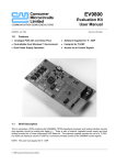
Power Requirements
The OIU module requires an AC power source of between 85 and 264 volts AC, 50 or 60 Hz. (The
module will draw approximately 1A @ 120 VAC). A connector is provided for connection of the AC power
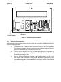
to the switching power supply on the OIU. Pin number 1 of this connector is the LINE or HOT terminal,
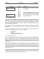
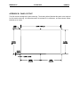
pin number 2 is the NEUTRAL terminal. A spade connector provides the GROUND connection. See
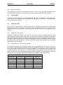
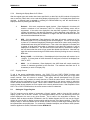
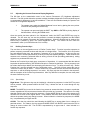
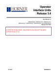
Figure 2-1 for the locations of the AC power and ground connections.
2.3
Communications Cable
Horner APG offers a six-foot communications cable, fully assembled and tested. If the user wants to
build a custom cable, the information is supplied in appendix A of this manual. This cable will allow direct
connection to any Series 90 PLC. It has the identical pinout as the GE Fanuc Hand-Held Programmer
Cable. If a printer is not connected to the RS-232 port, a "loopback" connector should be present on the
RS-232 port. This connector consists of jumpers between pins 2 & 3 (TXD & RXD) and pins 7 & 8 (CTS
& RTS).
PAGE 14
CH. 2
19 AUG 2000
Power Terminal
MAN0063-02
Ground Lug
Figure 2.1 – OIU350 Printed Circuit Board
2.4
Series 90 CPU Configuration
Before attempting communications between the OIU module and the Series 90 CPU, the Series 90 CPU
must be configured as follows;
A.
The password must be disabled in the Series 90 CPU using the GE Fanuc Hand-Held
Programmer or Logicmaster 90 (see the Series 90 User's Manual for details). Failure to
disable the password will prevent access to the PLC's data.
B.
The PLC ID must be set to null, using the Hand-Held Programmer or Logicmaster 90
(see the Series 90 User's Manual for details). An ID with a value other than null will
prevent access to the PLC's data.
C.
Only one Series 90 CPU can be accessed on the RS485 connection, the SNP "multidrop" network is not supported by the OIU module. Attempting to communicate to more
than one PLC will prevent access to any PLC data. The Horner APG SNP Multiplexer
(HE693SNPMPX) will allow multiple SNP devices, including the OIU350, to be connected
to one Series 90 PLC.
MAN0063-02
19 AUG 2000
PAGE 15
CH. 3
CHAPTER 3: INITIAL OPERATION
This chapter assumes that the OIU module has been mounted and that the communications cable has
been properly connected. Power can now be applied to the Series 90 and to the OIU module. The
display on the OIU module should respond with the following sign-on message;
HORNER ELECTRIC, INC.
OIU350 SNP V1.00
This message will remain on the VF display for approximately 3 seconds. If the sign-on message does
NOT appear on the VF display, consult the troubleshooting chapter. After the sign-on message has been
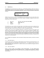
displayed for 3 seconds, the first two lines of the "MAIN MENU" will be displayed on the VF display;
→ RS485 Set-up
RS232 Set-up
3.1
Running the Self Test
At this point, the module is in a mode whereby the operator may select a MAIN MENU item. Navigation
through the OIU module's menu system is discussed in detail later in this manual, however the SELF
TEST should be executed during the initial operation in order to verify that the OIU module is properly
connected and fully functional. To do this, press and hold the "down arrow" key until the menu pointer
reaches the "Self Test" menu line (the Self Test is the sixth and final menu selection, the pointer will stop
when it reaches the Self Test line). Press the ENTER key to begin the Self-Test. The Self Test will
perform the following eight tests:
1.
2.
3.
4
5.
6.
7.
8.
System RAM memory test,
Keypad / VF Display test,
RS-485 Loopback test,
RS-232 Loopback test,
Real-time calendar clock test,
VF display contrast test,
Non-Volatile RAM test, and
Watchdog reset test.
The system memory test will display the amount of memory (in "K" bytes) present, this value should be
32K bytes. If a value other than 32K is displayed following completion of the RAM test, a serious
hardware problem exists.
When the Keypad / VF display test is running the message "Press a key..." will be displayed. Each time
the user presses a key on the keypad, the key's value is displayed on the second line of the VF display. If
a key is pressed and its value is not displayed on the VF display, a keypad problem exists. By pressing
the "SHIFT" and "ENTER" keys simultaneously, the keypad / display test is terminated.
PAGE 16
CH. 3
19 AUG 2000
MAN0063-02
The RS485 and RS232 loopback tests are valid only if the special "loopback" connectors are present on
each port. If the loopback connector is present, and the test passes, an OK message will be displayed. If
the tests fails with a loopback connector present, an ERROR! message is displayed and a port failure is
indicated. In the event of test failure, with or without loopback connector, pressing "ENTER" will allow the
self-test to continue.
The real time calendar clock test will show the unit's current date and time. If, after pressing an arrow
key, the time (seconds) is not changing, an error is present. (If desired, the time may be set at this time.
See "Setting the Calendar Clock", later on in this Chapter.) Pressing ENTER" will allow the self-test to
continue.
The VF display contrast control test will allow users to adjust the display contrast by pressing the up and
down arrows. Most users leave the display set at maximum contrast. Pressing "ENTER" will allow the
self-test to continue.
The non-volatile RAM test requires the user to cycle the OIU module's power. A pattern is written to the
OIU's NV-RAM memory and this pattern is checked following power-up. If the pattern is valid, the NVRAM test will pass. If the OIU module displays a NV-RAM FAIL message, the battery-backed memory
socket is defective.
The watchdog test will simply perform a hardware reset of the OIU module (just as if the power had been
turned off and then back on).
If any of these tests fail, refer to chapter 7, troubleshooting.
3.2
Operating Modes
The OIU module operates in two modes: SETUP mode and AUTORUN mode. When shipped from the
factory, the module will enter SETUP mode when powered up. The module can be customized and
configured while in SETUP mode and then placed in AUTORUN mode. Both modes are briefly discussed
below.
3.3
Set-up Mode
SETUP mode is designed for use by the OEM for configuration and customization of the OIU module.
When in SETUP mode, the OEM can configure the module's serial port communication parameters,
define custom VF display "screens", monitor and change PLC data registers, and perform other
configuration operations. A password can be defined while in SETUP mode to prevent access to SETUP
mode once the module has been placed in AUTORUN mode. The module is placed into AUTORUN
mode from the SETUP mode.
3.4
Autorun Mode
AUTORUN mode is designed for use by the OEM's end customer. Once the module has been placed in
AUTORUN mode, only the custom VF display "screens" can be accessed. When in AUTORUN mode,
the module will automatically enter the AUTORUN mode after power-up. In order to return to SETUP
mode, the user must correctly enter the optional password.
MAN0063-02
19 AUG 2000
PAGE 17
CH. 4
CHAPTER 4: THE MAIN MENU
When shipped from the factory, the OIU module will display the sign-on message for approximately 3
seconds following power-up followed by the display of the MAIN MENU. The MAIN MENU consists of six
menu items;
RS485 Set-up
RS232 Set-up
PLC Data Access
Customization
Set Clock
Self Test
Since the VF display only provides two lines, only two of the menu items will be displayed at a time. A
flashing "pointer" is displayed in the leftmost display column to designate which menu item is currently
"active". The menu pointer is positioned using the UP and DOWN arrow keys on the front panel keypad.
If the pointer is on the second line of the display and the DOWN arrow key is pressed, the display will
"scroll" to reveal the next menu item and the pointer will point to the newly displayed selection. Once the
end of the menu is reached, the display will no longer scroll down.
Display
→RS485 Set-up
RS232 Set-up
RS485 Set-up
→RS232 Set-up
Key(s)
Comments
When the first two lines of the MAIN MENU are
displayed, the pointer is moved by pressing the
DOWN arrow key.
The DOWN arrow key will continue to move the
pointer until the last menu item is reached.
RS232 Set-up
→PLC Data Access
PLC Data Access
→Customization
Customization
→Set Clock
When the bottom of the menu is reached, the
pointer will no longer move when the DOWN
arrow key is pressed, however the UP arrow key
will cause the pointer to move back up through
the menu items.
Set Clock
→Self Test
When the menu pointer has been moved to the desired menu item, the ENTER key is pressed to activate
the selected function.
PAGE 18
CH. 4
4.1
19 AUG 2000
MAN0063-02
RS485 Set-up
The RS485 Set-up is the first item on the main menu. It is selected by placing the main menu pointer on
the RS485 Set-up menu item and pressing the ENTER key. This selection allows the user to configure
the OIU module's SNP port communications parameters. Doing so will cause the display to change to the
following;
→Baud Rate: 19200
Parity:
Odd
RS485 Set-up is also menu oriented. The RS485 Set-up menu consists of four menu items which can be
configured. Each menu item is shown below with the range of acceptable configuration values and (in
larger type) the factory default value;
1.
2.
3.
4.
Baud rate:
Parity:
Data bits:
Stop bits:
(300, 600, 1200, 2400, 4800, 9600, 19200)
(None, Odd, Even)
(7, 8)
(1, 2)
The RS485 Set-up menu is similar to the Main Menu in that a flashing menu pointer is displayed in the
leftmost position of the VF display to designate which menu item is currently active. This menu differs
from the Main Menu in that all four-menu items each contain a configurable parameter.
A different value for one of the configurable parameters is selected by moving the menu pointer to the
desired item and pressing the RIGHT or LEFT arrow keys to sequence through the available values.
Once the desired value is shown, the ENTER key must be pressed in order to invoke the selected
parameter. If the value shown is different from the current configuration, the configuration value will flash.
This is to inform the user that the current operation has not yet been put into effect. If the UP or DOWN
arrow keys are pressed (moving the menu pointer) before the ENTER key is pressed, the original value is
restored for the current parameter.
All of the RS485 port configuration values are retained in battery-backed memory and will be invoked at
power-up.
4.1.1
Baud Rate Selection
The baud rate is the rate at which data is passed between the OIU module and the Series 90 CPU. This
value is determined by the configuration of the Series 90 CPU. To configure the OIU module for a
different baud rate, simply press the LEFT or RIGHT arrow key until the desired value appears, and then
press the ENTER key.
4.1.2
Parity Type Selection
Parity is a type of "built-in" error checking for serial communications. The OIU module's parity
configuration must match that of the slave Series 90 CPU. To configure the OIU module for a different
type of parity, simply press the LEFT or RIGHT arrow key until the desired value appears, and then press
the ENTER key.
MAN0063-02
4.1.3
19 AUG 2000
PAGE 19
CH. 4
Data Bit Selection
The number of data bits must also match that used by the Series 90 CPU. To configure the OIU module
for a different data bit parameter, simply press the LEFT or RIGHT arrow key until the desired value
appears, and then press the ENTER key.
4.1.4
Stop Bit Selection
The number of stop bits must also match that used by the slave Series 90 CPU. To configure the OIU
module for a different stop bit parameter, simply press the LEFT or RIGHT arrow key until the desired
value appears, and then press the ENTER key.
4.1.5
Returning to the Main Menu
When all of the RS485 serial port parameters have been configured, the user may hit the "MODE" key to
return to the main menu. This will cause the module to return to the MAIN MENU, with the pointer on the
"RS485 Set-up" selection.
4.2
RS232 Set-up
The RS232 Set-up is the second item on the main menu. It is selected by placing the main menu pointer
on the RS232 Set-up menu item and pressing the ENTER key. This selection allows the user to
configure the OIU module's programmer/printer port communications parameters. Doing so will cause
the display to change to the following;
→Baud Rate: 19200
Parity:
Odd
RS232 Set-up is also menu oriented. The RS232 Set-up menu consists of four menu items which can be
configured. Each menu item is shown below with the range of acceptable configuration values and (in
larger type) the factory default value;
1.
2.
3.
4.
5.
Baud rate:
Parity:
Data bits:
Stop bits:
Main Menu
(300, 600, 1200, 2400, 4800, 9600, 19200)
(None, Odd, Even)
(7, 8)
(1, 2)
The RS232 Set-up menu is similar to the Main Menu in that a flashing menu pointer is displayed in the
leftmost position of the VF display to designate which menu item is currently active. This menu differs
from the Main Menu in that all four-menu items each contain a configurable parameter. This menu is
virtually identical to the RS485 Set-up menu.
PAGE 20
CH. 4
19 AUG 2000
MAN0063-02
A different value for one of the configurable parameters is selected by moving the menu pointer to the
desired item and pressing the RIGHT or LEFT arrow keys to sequence through the available values.
Once the desired value is shown, the ENTER key must be pressed in order to invoke the selected
parameter. If the value shown is different from the current configuration, the configuration value will flash.
This is to inform the user that the current operation has not yet been put into effect. If the UP or DOWN
arrow keys are pressed (moving the menu pointer) before the ENTER key is pressed, the original value is
restored for the current parameter.
All of the RS232 port configuration values are retained in battery-backed memory and will be invoked at
power-up.
4.2.1
Baud Rate Selection
The baud rate is the rate at which data is passed between the OIU module and the serial printer. This
value must match that set on your serial printer or IBM compatible computer. To configure the OIU
module for a different baud rate, simply press the LEFT or RIGHT arrow key until the desired value
appears, and then press the ENTER key.
4.2.2
Parity Type Selection
Parity is a type of "built-in" error checking for serial communications. The OIU module's parity
configuration must match that of the serial printer or IBM compatible computer. To configure the OIU
module for a different type of parity, simply press the LEFT or RIGHT arrow key until the desired value
appears, and then press the ENTER key.
4.2.3
Data Bit Selection
The number of data bits must also match that used by the serial printer or IBM compatible computer. To
configure the OIU module for a different data bit parameter, simply press the LEFT or RIGHT arrow key
until the desired value appears, and then press the ENTER key.
4.2.4
Stop Bit Selection
The number of stop bits must also match that used by the serial printer or IBM compatible computer. To
configure the OIU module for a different stop bit parameter, simply press the LEFT or RIGHT arrow key
until the desired value appears, and then press the ENTER key.
4.2.5
Returning to the Main Menu
When all of the RS232 serial port parameters have been configured, the user may hit the "MODE" key to
return to the main menu. This will cause the module to return to the MAIN MENU, with the pointer on the
"RS232 Set-up" selection.
4.3
PLC Data Access
The OIU module is capable of monitoring the system memory registers inside the Series 90 CPU. The
user can also modify many of these registers using the OIU module.
MAN0063-02
19 AUG 2000
PAGE 21
CH. 4
To enter the PLC Data Access mode, simply move the Main Menu pointer to the PLC Data Access line
and press the ENTER key, the following will appear on the VF display;
Enter Data Type:
%R
At this point, the user must select the type of register and the register "offset" or register "number" to
monitor or modify. As always, the user can return to the main menu by pressing the MODE key.
4.3.1
Data Type Selection
The Series 90 utilizes several different data "types". This data is used by the Series 90 ladder program to
represent I/O points, internal coils, data registers, etc. The Series 90 data types accessible via the OIU
module are listed below:
Designator
Register Type
%R
%AI
%AQ
%I
%Q
%T
%M
%S
%SA
%SB
%SB
%G
Register (word)
Analog Input (word)
Analog Output (word)
Discrete Input (bit)
Discrete Output (bit)
Discrete Temporaries (bit)
Discrete Internals (bit)
System Discretes (bit)
System Discretes (bit)
System Discretes (bit)
System Discretes (bit)
GeniusTM Global data (bit)
Pressing the UP or DOWN arrow keys will cause the register "type" field to sequence through the types
listed above. The register "offset" or number is entered via the numeric keypad. A maximum of 4 digits
are allowed. Note that the LEFT arrow key can be used to perform a "backspace" operation on the
numeric entry, and the CLEAR key can be used to completely erase the numeric entry. When the desired
register type and number are displayed, the ENTER key is pressed to invoke the data monitor mode.
For example, if the user wishes to monitor the analog output #30 (%AQ30), the following sequence would
be used;
Display
RS232 Set-up
→PLC Data Access
Enter Data Type:
%R
Enter Data Type:
%AI
Key(s)
Comments
ENTER
With the Main Menu pointer on the PLC Data
Access line, press the ENTER key...
Press the down arrow button until the %AQ
register type appears (in this case, twice)...
PAGE 22
CH. 4
19 AUG 2000
Display
Enter Data Type:
%AQ
Key(s)
DEF
3
MAN0063-02
Comments
The register number is selected using the
numeric keypad...
DEL
0
%AQ0030
%AQ0031
4.3.2
0
0
ENTER
With both the register type and number correctly
chosen, the ENTER key will cause the module
to enter the monitor mode. Pressing the MODE
key will cause the module to return to the
register selection mode.
PLC Data Monitoring
Following the above example, the OIU module will display the register type, register number and the
current value of the register in the PLC (provided that the OIU is properly connected to a Series 90 PLC).
The actual format of the displayed data depends on the type of register displayed and on the display
"base". Upon entry into the monitor mode, the "decimal" display base is always selected. The selected
register's value will be displayed on the first line of the VF display in 16-bit unsigned decimal format. Up
to five decimal digits will be displayed.
While in monitor mode, the UP and DOWN arrow keys can be pressed to sequence through the available
register numbers. If the "end" of the selected register space is reached, the module will "wrap around" to
the first value.
Pressing the DEC/HEX/BIN key will cause the format of the displayed data to change. Each successive
pressure of the DEC/HEX/BIN key will cause the format to change to;
1.
2.
3.
4.
4.3.3
16-bit Hexadecimal
16-bit Binary
1-bit (displayed as "On" or "Off")
16-bit two's complement signed decimal
Reading Decimal Data
When PLC data is displayed during monitor mode in the 16-bit two's complement signed decimal base,
the values displayed will contain up to five decimal digits and an optional sign if the value displayed is
negative. Leading zeroes are suppressed. If the register type selected is a "word" value (%R, %AI, or
%AQ), the second line of the VF display will contain the next consecutive register number. If the last
available data item is displayed on the first line of the VF display, the second line will contain the first
register number.
If the register type being displayed is a "bit" type register, the first line of the VF display will contain a
decimal value that represents the current state of the selected bit AND the next consecutive 15 bits. The
second line of the display will contain a value that represents the current state of the subsequent 16 bits
of the same type. For instance, if the user chooses to display bit %I9, the first line will contain a decimal
value that represents the state of bits %I9 to %I24, while the value on the second line will correspond to
registers %I25 to %I40.
When displaying bit data, the register tables can be thought of as "circular". This means that if a 16-bit
"bit" register is displayed that includes the last available bit register of a given type, the remaining bits of
the displayed value will represent the first bits of that type. For example, if %I505 is displayed (with the
last %I register being %I512) the value is represented as follows;
MAN0063-02
%I505
19 AUG 2000
256 dec
PAGE 23
CH. 4
(0000000100000000 binary)
%I505
%I512
%I1
%I8
The UP and DOWN arrow keys allow the user to "scroll" through the selected register table. If the
selected register table is a "bit" type register, each activation of the UP or DOWN arrow keys will cause
the displayed value to increment or decrement to by 16 bits. During 16-bit register displays, the UP and
DOWN arrow keys will cause the displayed value to increment or decrement by one.
4.3.4
Reading Hexadecimal Data
When PLC data is displayed during monitor mode in the 16-bit Hexadecimal base, the values displayed
will contain four hexadecimal decimal digits, followed by the "H" character. Leading zeroes are displayed.
All other attributes are identical to those described above for decimal display of data.
4.3.5
Reading Binary Data
When PLC data is displayed during monitor mode in the Binary base, only ONE 16-bit binary value will be
displayed on the second line of the VF display.
The UP and DOWN arrow keys allow the user to "scroll" through the selected register table. If the
selected register table is a "bit" type register, each activation of the UP or DOWN arrow keys will cause
the displayed value to increment or decrement by 1 bit. This will give the effect of "shifting" the binary
value to the right or left. During "word" register displays, the UP and DOWN arrow keys will only cause
the displayed value to increment or decrement by one 16-bit register.
4.3.6
Reading On/Off Data
When PLC data is displayed during monitor mode in the On/Off base, two consecutive registers, either bit
or word type will be represented. If a word type register is selected, the value displayed (On or Off) will
represent the state of the LEAST SIGNIFICANT BIT of the word register. If a bit register is selected, two
consecutive bit values will be displayed.
The UP and DOWN arrow keys will function exactly as described above for the binary base.
4.4
Changing PLC Data
During monitor mode, the user can change the PLC data value displayed and cause the OIU module to
"write" the new value to the PLC. This is done by selecting the desired "base" for the display and then
pressing the RIGHT arrow key. This will cause the selected data item to flash, indicating that the numeric
entry mode is active. The action taken by the OIU module depends on the current display base selected.
4.4.1
Writing Decimal Data
If the 16-bit two's complement signed decimal base is selected when numeric entry mode is invoked, the
current value of the register on the top line of the VF display will flash. If this value changes, the
PAGE 24
CH. 4
19 AUG 2000
MAN0063-02
displayed value will be updated. If the user presses one or more numeric keys (0 through 9), the value
entered will then be displayed in place of the original PLC data value. The LEFT arrow key can be used
to perform a "backspace" operation and the CLEAR key can be used to completely erase the numeric
entry.
When the desired replacement value has been numerically entered, the ENTER key is pressed to cause
the OIU module to "write" the value to the PLC. The following sequence assumes that the OIU module is
already monitoring register %AQ30. This sequence will write a decimal value of -1234 to the register;
Display
%AQ0030
%AQ0031
0
0
%AQ0030
%AQ0031
0
0
Key(s)
+
QZ
1
DEF
3
%AQ0030 1234
%AQ0031
0
%AQ0030 -1234
%AQ0031
0
Comments
With the desired register on the top line of the
VF display, pressing the RIGHT arrow key will
invoke "numeric entry" mode, causing the
current value to flash.
ABC
2
GHI
4
This key sequence will cause the entered value
to be displayed in place of the original PLC
value (nothing is written to the PLC until the
ENTER key is pressed).
SHIFT
The SHIFT key must be used in order to access
the "-" function.
ENTER
Pressing the ENTER key causes the new value
to be written to the PLC. Pressing the MODE
key causes the module to return to the register
selection mode.
If no numeric value has been entered when the ENTER key is pressed, nothing is written to the PLC.
After the ENTER key has been pressed and the new value is written to the PLC, the OLD value might
appear on the display for an instant. This is because the OIU module will not recognize that the value
has changed until the PLC responds to the OIU module's request for the current value. The old value will
be displayed for the amount of time required to write the new value and then read the new value from the
PLC.
4.4.2
Writing Hexadecimal Data
Writing data to the PLC while displaying data in the Hexadecimal base is identical to that in decimal base
except that data is entered in up to four hexadecimal digits. However, alphanumeric values (A-F), are not
writable.
4.4.3
Writing Binary Data
When the binary base is selected and the numeric entry mode is invoked, only the LEAST SIGNIFICANT
BIT of the displayed binary value will flash. The "1" key can be pressed to force this bit to it's ON state
while the "0" key will force this bit to it's OFF state. The new value will not be written until the ENTER key
is pressed.
MAN0063-02
4.4.4
19 AUG 2000
PAGE 25
CH. 4
Writing On/Off Data
The On/Off base is similar to the binary base in that the "1" and "0" keys will cause the displayed bit to
turn ON and OFF respectively. The new value will not be written until the ENTER key is pressed.
4.5
Customization
The fourth item on the Main Menu is the CUSTOMIZATION option. To invoke the customization menu,
move the main menu pointer to the customization line and press the ENTER key. The customization
menu is discussed in Chapter 5.
4.6
Setting the Clock
The next item on the Main Menu is the SET CLOCK option. This option allows the user to perform three
functions; set the clock for the proper date and time, select the registers in the PLC to which the OIU will
download date and time information, and select the time interval at which the OIU updates the PLC
registers.
4.6.1
Setting the Time and Date
Immediately following the selection of the Set Clock menu item, a screen is displayed with the current
stored setting for day of the week, month, date, year, and time. Pressing the right arrow key allows the
desired parameter to be selected, and pressing the up and/or down arrow keys allows the current value to
be changed. Note that the day of the week is not changeable. The OIU automatically selects the proper
day of the week for the date selected. As soon as the time and date are set properly, the user presses
ENTER to store the new values.
4.6.2
Selecting the PLC Time and Date Registers
As mentioned previously, time and date information can be downloaded from the OIU to a bank of six
PLC registers. After setting the current time and date as described in section 4.6.1, the user is prompted
to enter the register number for the first of these six registers (For a description of the six registers and
the data they contain, see Table 4-1). To enter the starting clock register, the user must type in the
register number (type %R is automatically selected) followed by ENTER. If the downloading of time and
date to the PLC is not desired, pressing the CLEAR key (then ENTER) disables the function.
Table 4.1 – Time and Date Registers
Reg Number
Data Stored
Data Range
Data Type
1
Hour
0-23
BCD
2
Minute
0-59
BCD
3
Day of Week
1-7
BCD
4
Month
1-12
BCD
5
Date
1-31
BCD
6
Year
1991-????
BCD
PAGE 26
CH. 4
4.6.3
19 AUG 2000
MAN0063-02
Selecting the Time and Date Update Interval
If the starting time and date register has been selected, the user is next prompted to set the interval at
which the time and date registers are updated. By pressing the up and/or down arrows, the user can
toggle through the available choices. The choices are as follows:
1.
2.
3.
4.
At power-up only
Once per minute
Once per hour
Once per day
Once the appropriate interval is displayed, pressing ENTER completes the interval selection. This also
completes the SET CLOCK procedure.
4.7
The Self Test
The sixth and final Main Menu item is the SELF-TEST. The execution of the OIU module's self-test is
described in Chapter 3.
MAN0063-02
9 AUG 2000
PAGE 27
CH. 5
CHAPTER 5: THE CUSTOMIZATION MENU
The OIU module has been designed for maximum configurability to allow the user to implement the
module in most any application. This section describes in detail how to program the custom VF display
screens and how to place the module into AUTORUN mode.
Pressing the ENTER key when the Main Menu pointer is on the Customization item will cause the OIU
module to enter the CUSTOMIZATION MENU. This menu consists of 8 menu items;
1.
2.
3.
4.
5.
6.
7.
8.
Set Password
Define Display
Set Trigger Register
Autorun
Adjust Brightness
Define Function Keys
Set LED Register
High User Screen Number
Movement through the Customization menu and selection of an item in the customization menu is
identical to that of the Main Menu (see section 4).
5.1
Setting the Password
Once the OIU module is placed into the AUTORUN mode, it will stay in this mode (even through a power
failure) until the user performs the key sequence to exit into SETUP mode. The OEM can define a
password to prevent the end user from entering the SETUP mode.
The first item on the customization menu is the SET PASSWORD function. When shipped from the
factory, the password function is disabled. To configure the password, the menu pointer is placed on the
Set Password menu item and the ENTER key is pressed. One of the following messages will appear on
the VF display;
If no password exists:
New Password?
--
If a password has been defined:
Old Password?
--
If a password has previously been defined, the user must correctly enter the old password before a new
password can be defined. If the ENTER key is pressed before any password characters are entered, the
password is disabled. During password entry, the LEFT arrow key can be used to perform a "backspace"
operation.
The password is numeric, and can contain up to 20 numerals (0 through 9).
5.2
Defining a Custom Display
As stated previously, the OIU module can be programmed with up to 250 custom VF display "screens".
Selecting the second item on the customization menu (Define Display) will cause the following message
to appear on the VF display;
Enter Display #
(0 to 249): 000
PAGE 28
CH. 5
5.2.1
19 AUG 2000
MAN0063-02
Selecting the Display Number
At this point the user must enter a screen number (0 through 249) that represents the screen number to
be configured. As soon as a numeric key is entered, the text of the selected screen will be displayed, and
a flashing cursor will appear in the first display position.
When shipped from the factory, all 250 of the programmable display screens are filled with spaces,
therefore the display will appear to be "blank".
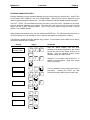
READ
ONLY
READ/
WRITE
∧
EXT
CODE
∨
EXT
CODE
∧
PUNCT
∨
PUNCT
COPY
TO
COPY
FROM
HOME
SPACE
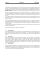
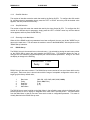
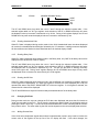
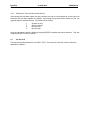
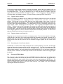
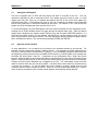
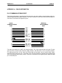
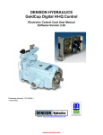
Figure 5.1 - Function Key Customization Insert
5.2.2
Using the Function Key Customization Insert
Before going ahead with the screen customization process, it is advisable for the programmer to insert
the customization insert over the 12 function keys. The function keys play a major part in the
programming of the unit. The exact function of each of the keys during the configuration process is
detailed later on in this chapter. A diagram of the function key insert is shown above.
5.2.3
Defining the Display Text
The user can configure the selected "screen" with up to 40 characters of text, each character of which can
be any displayable ASCII character. The text for the selected display screen is defined one character at a
time.
ALPHANUMERIC CHARACTER DISPLAY
Entering Alphanumeric Characters is accomplished via the numeric keypad. Each key (except 0) is
labeled with both a numeral and two or three letters. The letters correspond to the standard labeling on a
telephone keypad, with the exception of the 1 key. For example, the "2" key contains the alphabetical
label of "ABC". To enter an "A" press the key once. To enter a "B", press the key twice. To enter a "C",
press three times. To enter a "1" press four times. To change the case, (for example, from "A" to "a")
press the shift key after choosing the proper letter.
PUNCTUATION CHARACTER ENTRY
Entering punctuation characters involves the use of two of the function keys. Keys F7 and F8 are labeled
"PUNCT UP" and "PUNCT DOWN" on the programming insert. These keys are used to sequence up and
down through the set of punctuation characters. Also, a space character can be inserted by pressing the
F12 key. The chart on Page 5-6 lists all available punctuation characters.
MAN0063-02
9 AUG 2000
PAGE 29
CH. 5
EXTENDED CHARACTER ENTRY
Entering characters from the extended character set also involves using two function keys. Keys F5 and
F6 are labeled "EXT CODE UP" and "EXT CODE DOWN". These keys are used to sequence up and
down through the extended character set. The chart on Page 5-7 lists all available extended characters.
The LEFT , RIGHT, UP and DOWN arrow keys are used to move the cursor. Movement of the cursor
does not affect the characters on the display. The cursor will "wrap" from one line to the other if moved
beyond the last (or first) character position. The F11 key can be used to bring the cursor to screen
position 1, the "HOME" position.
When finished with character entry, the user presses the ENTER key. The OIU module will then return to
the "Enter Display #" mode, allowing the user to select a new display for configuration or editing.
The following example reviews the character entry process. In the example, Screen #200 is to be used to
enunciate a machine failure condition.
Display
Enter Display #
(0 to 249): 000
Key(s)
ABC
2
Comments
DEL
0
DEL
0
ENTER
_
DEF
3
DEF
3
DEF
3
Hitting the "3" key three times causes an F to
appear in the first position. Right arrow moves
to the next position.
+
F_
Fa_
+
ABC
2
GHI
4
SHIFT
GHI
4
GHI
4
+
SHIFT
Fai_
JKL
5
JKL
5
TUV
8
TUV
8
+
SHIFT
Failu_
PRS
7
SHIFT
JKL
5
+
SHIFT
Fail_
After the "Define Display" item has been
selected on the Configuration Menu, the unit will
prompt the user for the display number to be
defined. This key sequence selects Screen
#200 and brings up a blank screen.
PRS
7
+
The next sequence of keys enters each letter in
succession.
Pressing the SHIFT key after
selecting the proper letter selects a lower case.
PAGE 30
CH. 5
19 AUG 2000
Display
Failur_
Key(s)
DEF
3
DEF
3
MAN0063-02
Comments
(Display Definition Example, continued)
+
SHIFT
Failure_
Failure!_
Enter Display #
(0 to 249): 000
F7
To add an exclamation mark to the end of the
message, the punctuation function key must be
used. Pressing F7 (PUNCT UP) once will cause
the exclamation mark to be displayed.
ENTER
Pressing the ENTER key will complete the
screen customization process. Another screen
may now be defined or edited.
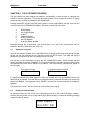
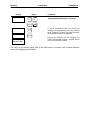
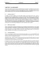
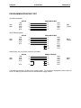
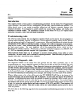
The charts on the following pages show all the alphanumeric, punctuation, and extended characters
which can be displayed by the OIU350.
MAN0063-02
9 AUG 2000
Figure 5.2 – Alphanumeric Character Set
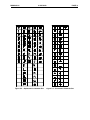
PAGE 31
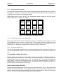
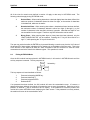
CH. 5
Figure 5.3 – Punctuation Character Set
PAGE 32
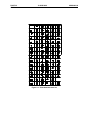
CH. 5
19 AUG 2000
Figure 5.4 – Extended Character Set
MAN0063-02
MAN0063-02
5.2.4
9 AUG 2000
PAGE 33
CH. 5
Defining PLC Data Display Fields
When defining a custom display screen, the user may also define up to four "fields" to be filled with data
from the PLC. A field is a group of one or more adjacent characters on the display. A field can be only
one character in length, or as long as 20 characters (an entire display line).
A data field is defined by placing special characters in the custom display screen during the screen's
definition. Two of these special characters exist to permit PLC data field definition.
READ/ONLY
(Blinking R)
READ/WRITE
(Blinking W)
Each of the characters, when placed in a custom VF display screen, will represent a single character of a
data field to be filled with register data from the PLC. The difference between the characters shown
above is:
1.
The character with the "blinking R" (alternating between an R and a solid block) will
define a data field that is READ ONLY. The user will not be able to modify the PLC data
register that is configured for display in this field during AUTORUN mode.
2.
The character with the "blinking W" (alternating between a W and a solid block) will
define a data field that is READ/WRITE. The user will be able to modify the value being
read from the PLC and write the modified value to the PLC during AUTORUN mode.
READ/WRITE fields will continually monitor and update the displayed PLC data value,
just as the READ ONLY fields.
The data field characters are accessed by using the function keys with the programming insert installed
(see Section 5.2.1). Each field type (READ ONLY, READ/WRITE) has its own function key (F1-F2).
READ ONLY fields are accessed by simply pressing the F1 function key. READ/WRITE fields are
accessed by pressing the F2 function key.
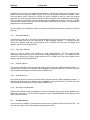
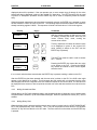
Consider the following custom display screen:
This screen defines two data fields, the first is a READ WRITE field composed of three characters starting
at the eighteenth character on the first line of the display. The second line is a READ/ONLY field
composed of 5 characters starting at the 16th character on the second line of the display. When the
ENTER key is depressed following the definition of the screen just described, the OIU will prompt the user
for entry of the data type for each of the fields defined.
PAGE 34
CH. 5
5.2.5
19 AUG 2000
MAN0063-02
Selecting the PLC Data Items
If more than four data fields are defined in a custom VF display screen, an error message will be
displayed to that effect. When any key is pressed, the OIU module will return to the screen-editing mode,
allowing the operator to reduce the data fields.
Otherwise, the module will prompt the user to select a data register type and number. The UP and
DOWN arrow keys are used in this mode to sequence through the available register types, and the
register number is entered numerically (up to four digits).
Display
Fault:
Action:
Enter type for
Field 1: %R
Enter type for
field 1: %R 0001
Enter type for
field 1: Decimal
Key(s)
ENTER
QZ
1
ENTER
When finished editing a custom display screen,
the user presses the ENTER key.
The user must now define the PLC data register
type and number for each field. This example
will configure field #1 for %R1 and field #2 for
%AQ30.
With the register type selected, the register
number is entered numerically.
ENTER
Enter type for
field 2: %R
+
Enter type for
field 2: %AI
+
Enter type for
field 2: %AQ
Comments
WXY
9
Enter type for
field 2: %AQ0009
ENTER
Enter type for
field 2: Decimal
ENTER
When the ENTER key is pressed, the module
will now prompt the user to select the base for
each field. If a different base other than decimal
was desired, pressing the DEC/HEX/BIN key
would cause the base to change. ENTER is
pressed when the base is correct.
MAN0063-02
5.2.6
9 AUG 2000
PAGE 35
CH. 5
Selecting the Display Base for PLC Data
After the register type and number have been specified for a data field, the OIU module will prompt the
user to enter the "base" that is to be used during display of the data field. Four display base options are
provided. A different base is selected by pressing the DEC/HEX/BIN key until the desired base is
displayed, and then pressing the ENTER key.
5.2.7
1.
Decimal - 16-bit two's complement signed decimal. Data displayed in this base will
contain a maximum of six characters (-32767 to -32768) and leading zeroes will be
suppressed. If the value to be displayed in the data field is greater in length than the
number of characters in the data field, asterisks (*) will be displayed in the data field. The
data field can be fewer than five characters in length if the user insures that the value will
not exceed the allotted data field size.
2.
HEX - 16-bit hexadecimal. Data displayed in this base will contain a maximum of four
characters (0000 to FFFF) and leading zeroes will be displayed. The user is encouraged
to place an "H" character immediately following the data field in order to easily identify the
hexadecimal base during AUTORUN mode. If the value to be displayed in the data field
is greater in length than the number of characters in the data field, asterisks (*) will be
displayed in the data field. The data field can be fewer than four characters in length if
the user insures that the value will not exceed the allotted data field size. Note that only
digits 0-9 can be entered during AUTORUN mode, effectively limiting the user to entering
BCD data .
3.
Binary, On/Off - 1 to 16-bit binary. Data displayed in the binary base will consist of up to
16 digits. If a binary base of three characters is configured, one bit will be displayed as
"ON" or "OFF".
4.
ASCII - 1 to 16 characters. Data displayed in the ASCII base will contain exactly the
number of characters specified by the data field. The maximum data field size is 16
characters (an entire VF display line).
Copying Screens
To aid in the screen configuration process, the "COPY TO" and "COPY FROM" functions were
developed. These functions, F9 and F10 on the programming function key insert, allow you to copy entire
screen contents from one screen to another. This greatly reduces development time for those
applications where many screens are nearly identical, or follow the same format. When COPY TO is
selected during the configuration of a screen, the user is prompted for the screen number to which the
current screen's contents will be copied. When COPY FROM is selected, the user is prompted for the
screen number whose contents are to be copied to the currently selected screen. After completion of the
COPY TO or COPY FROM function, the current screen number is maintained.
5.3
Setting the Trigger Register
The PLC program can be written to incorporate a "trigger" register, used to force the OIU module to
display or print one of the 250 screens. By utilizing this feature, the PLC can selectively control the
screen displayed to the user at any given moment. This is useful in the enunciation of alarms. For
instance, when an alarm condition is detected in the PLC ladder diagram, the PLC can use the "trigger"
register to force the OIU to display a screen which notifies the user of the alarm condition. There are a
variety of ways in which this feature can be utilized, and also a variety of ladder logic schemes which can
be implemented to accomplish them. For a selection of detailed examples, see the Horner APG Operator
Interface Applications Guide, Publication Number HFK-90-151.
PAGE 36
CH. 5
19 AUG 2000
MAN0063-02
For the trigger register feature to be active, the user must choose which of the PLC's registers (%R) is to
be used as the "trigger" register. This is accomplished by selecting the "Set Trigger Register" option from
the configuration menu. The OIU will prompt the user to enter the desired %R register. Typing the
register number followed by ENTER will assign the register. If no PLC triggering is desired, setting the
%R offset to NULL will disable the feature. This can be done by pressing CLEAR, then ENTER.
5.3.1
Triggering Screen Changes
When PLC triggering is enabled, the OIU module will continually monitor the value of the specified
register during AUTORUN mode. Triggering the OIU to change screens by the PLC is a two step
process. The first step is to set the lower eight bits of the trigger register with a value of 0-249, the
screen number that is to be changed to. This is typically accomplished with a MOVE function (see your
GE Fanuc Series 90 Reference Manual). The second step is to set bit 9 (decimal value 256) of the
trigger register, without overwriting the lower eight bits. This is typically accomplished with an OR
function. With bit 9 set, the OIU will change to the screen (0 to 249) defined by the lower eight bits of
the trigger register. It will then overwrite the trigger register with the screen number that was displayed
prior to the switch. Note that the user will not have the ability to change screens from the keypad while bit
9 of the trigger register is on, the PLC will have complete control over display selection. To return screen
selection control back to the user, bit 9 must be reset to 0.
5.3.2
Triggering Output to the Printer Port
Triggering output to the printer port is similar to changing screens. First, the lower eight bits of the trigger
register are set to the value of the screen that contains the information to be printed. Secondly, bit 10
(decimal value 512) is set without overwriting the lower eight bits. The information will then be printed
(along with the time and date), and the OIU will overwrite the trigger register with the current screen
number.
5.3.3
Determining the Current Screen Number
Occasionally, it is useful to know which screen the user is currently viewing. To do this, set the trigger
register to a decimal value between 250 and 255, and set bit 9 or 10. The OIU will overwrite the trigger
register with the current screen number, without changing screens. Note that when feedback to the
trigger register is desired, the function which is being executed (MOVE, OR, etc.) should be enabled by a
one-shot contact. Otherwise, the ladder logic will write over the information written to the trigger register
by the OIU.
5.4
Entering AUTORUN Mode
The next item on the customization menu is the AUTORUN selection. After the user has configured the
custom display screens and is ready to place the module in the AUTORUN mode, this option can be
selected by placing the menu pointer on the Autorun menu item and pressing the ENTER key. The
operator will be prompted to enter a "display number" from 0 to 249. This display number represents the
custom VF display screen that is to be shown after power-up. See Chapter 6 for more information
regarding AUTORUN mode operation.
MAN0063-02
5.5
9 AUG 2000
PAGE 37
CH. 5
Adjusting the Vacuum Fluorescent Display Brightness
The fifth item on the customization menu is the Vacuum Fluorescent (VF) brightness adjustment
selection. The OIU module allows the operator to adjust the display brightness via the front panel keypad
to compensate for differences in various installations. There are two methods whereby the operator can
access the VF brightness adjustment;
1.
The operator may select the "Adjust Brightness" menu item by placing the menu pointer
on this line and pressing the ENTER key.
2.
The operator can press and hold the SHIFT key AND the ENTER key during display of
the Main Menu, or during AUTORUN mode.
Once the module has been placed in the "adjustment" mode, the SHIFT and ENTER keys may be
released. The UP arrow key can now be pressed to increase the display brightness and the DOWN
arrow key can be pressed to decrease the display brightness. When the desired level is obtained, the
ENTER key is pressed to "store" the current brightness setting. The module will then enter the
customization menu (or AUTORUN mode if it is in effect).
5.6
Defining Function Keys
The next item on the configuration menu is "Define Function Keys". Function keys allow operators to
perform commonly executed functions with the push of a single button. The functions, 24 in all (function
key and shifted function key), are stored as a sequence of up to 64 keystrokes. In this way they are
similar to "macro" functions performed by a variety of computer software packages. These functions can
automate such commonly performed tasks as turning on and off bits (simulating pushbuttons), setting
registers to a pre-determined value, etc.
Because the Function Keys simply store a sequence of keystrokes, it is recommended that the desired
keystrokes be performed during AUTORUN mode prior to function key definition. The key sequence can
be written down and pre-tested, thus decreasing the chances of error. To define a function key, "Define
Function Key" must be selected from the Configuration menu. The OIU will then prompt the user to
"Press the Function Key to define..." Once a function key is pressed, the user can enter the desired key
sequence, or edit the existing sequence if one exists. Any keys may then be included in the sequence,
with the exception of the function keys themselves. After key definition is complete, the user must press
the same function key to exit.
5.6.1
Special Keys
Right Arrow: The right arrow key may be included in a function key sequence, but the SHIFT key must
first be pressed. When pressed without the SHIFT key, it allows the user to cursor through the key
sequence.
MODE: The MODE key is used in the function key process to access data from or change to a particular
screen, regardless of the current screen location at the time the key is pressed. The screen is not visibly
changed until the end of the function key sequence. Placing MODE 999 at the end of the sequence will
force the OIU to return to the original screen. In this fashion, data from other screens can be accessed
without the operator seeing any change in screen. When included in a function key sequence, the MODE
key is represented by an upper case M.
CLEAR: The clear key should be used following the MODE key to access data from or change to a
particular screen. For instance, the key sequence MODE CLEAR 100 ENTER would cause the OIU to
change to screen number 100. The CLEAR is represented by an upper case C when included in a
function key sequence.
PAGE 38
CH. 5
19 AUG 2000
MAN0063-02
ENTER: When included in a function key sequence, the ENTER key is represented by an upper case E.
SHIFT DELETE: Pressing the SHIFT then DELETE keys deletes a key from the function key sequence
during editing.
SHIFT INSERT: Pressing the SHIFT then INSERT key toggles between insert and overstrike mode, in
the editing of function key sequences.
5.6.2
Function Key Example
One useful task for a function key is to turn a bit in the PLC reference table "on" or "off". With this simple
function, function keys can replace pushbuttons which previously had to be hard-wired. In order to
change the status of a bit, a custom screen must exist which contains that data bit. This example will set
up a function key to turn on the RUN bit, illustrated previously in the example on Page 5-8.
Display
Key(s)
Comments
→Define FUNC Key
Hi User Screen #
Press the FUNC
key to define…
Define FUNC F1
_
The "Define Function Key" option is chosen from
the configuration menu.
MODE
ABC
2
Define FUNC F1
MC20E_
The function key to be defined is selected, and
the key sequence can now be entered.
F1
CLEAR
DEL
0
ENTER
Pressing SHIFT, then right arrow allows the first
READ/WRITE data field to be edited...
x
SHIFT
The first part of the sequence accesses the
screen containing the data to be turned on. This
is done by pressing the MODE key, followed by
CLEAR and the screen number, the same
keystrokes one would perform in AUTORUN
mode.
A "1", followed by ENTER sets the bit high.
Define FUNC F1
MC20E>_
1
Define FUNC F1
MC20E>1E_
MODE
QZ
WXY
9
Define FUNC F1
MC20E>1EM999_
Press the FUNC
key to define…
F1
ENTER
During playback of the function, the OIU will not
visibly change screens until the completion of
the entire sequence. Because no visible screen
change is desired, placing "MODE", "9", "9", "9"
at the end of the key sequence will prevent it.
WXY
9
WXY
9
With the key sequence complete, pressing the
function key ends the definition process.
Another function key can now be defined, or the
Configuration menu can be accessed by
pressing the MODE key.
MAN0063-02
5.7
9 AUG 2000
PAGE 39
CH. 5
Setting the LED Register
The OIU is equipped with 12 LED's that may display the state of I/O points in the PLC. The only
restriction is that they be tied to consecutive points. Any register type (bit or word) is valid. If a word
register type (%R, %AI, %AQ, etc.) is selected, the states of the first 12 bits of that 16-bit register are
indicated by the LED's. If a bit register type (%M, %I, %Q, etc.) is selected, the states of the bit specified
and the next consecutive 11 bits will be indicated by the LED's. For instance, if %I1 is set as the LED
register, the LEDs will display the status of points %I1 to %I12.
To set the LED register, the "Set LED Register" menu item must be selected from the configuration menu.
Pressing the UP and/or DOWN arrows will toggle through the different data types. After the desired
register type is displayed, the register number ("offset") may then be typed and ENTER pressed. If a
previously set register number is to be changed, the CLEAR key can be pressed to clear out the old
value, and the new one may now be entered. If no LED displaying is desired, setting the register offset to
NULL will disable the feature. This can be done by pressing CLEAR, then ENTER.
5.8
High User Screen Number
In many applications, it is not desired for all screens to be accessible directly by the end-user. For
example, a screen contains the message, "Machine Failure". That message is normally triggered by the
PLC when a machine failure actually occurs. However, if a user unwittingly changed to that screen from
the keypad (by pressing the arrow keys or MODE-CLEAR-screen #), it would appear to the operator that
the alarm was active when it was not. A parameter on the configuration menu, "High User Screen
Number", allows the OEM to set a screen boundary beyond which the end user may not access from the
keypad. If that boundary was set at 100, the end user could access only screens 0-100 from the keypad.
Screens 101-249 would be displayed only if triggered by the PLC. The "inaccessible" screens are also
useful for screens which are only sent to the printer, or screens which contain data only accessed during
a function key sequence. To set the "High User Screen Number" boundary, simply enter the last
accessible screen number followed by ENTER. When an end user presses the MODE key in Autorun
mode, he will be prompted to enter a screen number between 0 and the High Screen Number.
PAGE 40
CH. 5
19 AUG 2000
NOTES
MAN0063-02
MAN0063-02
19 AUG 2000
PAGE 41
CH. 6
CHAPTER 6: AUTORUN MODE
Once the OIU module has been placed in AUTORUN mode, it will remain in AUTORUN mode (even if the
power is turned off and back on) until the "exit" key sequence is entered. A password can also be used to
prevent access to the SETUP mode when in AUTORUN mode. When in AUTORUN mode, the screen
number configured as the "start" screen will be automatically displayed after power-up.
6.1
Changing "Screens"
As stated in the earlier chapters, up to 250 custom screens can be defined by the user. Once in
AUTORUN mode, (if the trigger register is not actively controlling screen display) any of the screens at or
below the high user screen boundary can be displayed by the user. This is accomplished by pressing the
MODE key. After the MODE key is pressed, the OIU will prompt the user for the desired screen number.
Pressing CLEAR will clear the screen number field, allowing another to be entered. For example, if the
user wants to display screen number 6, he simply presses the MODE key, followed by CLEAR, the "6"
key, and ENTER. As an alternative to the MODE key, the UP and DOWN arrow keys can be used to
"scroll" from the current screen through the available screens. If the power is lost to the OIU module, it
will always revert to the AUTORUN starting screen number when the power is restored.
6.2
Monitoring PLC Data
When a custom display is shown on the display during AUTORUN mode that contains one or more "data
fields" (READ/ONLY or READ/WRITE), the data field(s) will be filled with the current value of the defined
register from the PLC. The data value(s) will continually be updated as fast as the communications
protocol between the OIU module and the PLC will allow. When changing screens, blank spaces will
briefly be displayed in data registers until valid PLC data is received.
6.3
Changing PLC Data
When a custom display is shown during AUTORUN mode that contains one or more READ/WRITE "data
fields", the data field(s) will display the current PLC data identically to READ ONLY fields. These data
fields can, however, be changed by the user in
AUTORUN mode. To write a value to the PLC, the user must press the RIGHT arrow key until the
desired data field begins to flash. If no READ/WRITE data fields exist on the current custom VF screen,
the RIGHT arrow key will be ignored by the OIU module.
The user can now enter a value to be written to the PLC data register defined for the selected data field.
The field will continue to monitor and display the PLC data register until the first numeric key is pressed.
Once a numeric key has been pressed, the value entered will be displayed in the data field. During
numeric entry, the LEFT arrow key can be used to perform a "backspace" operation, and the CLEAR key
can be used to completely erase the numeric entry. Pressing the ENTER key completes the writing
process.
PAGE 42
CH. 6
19 AUG 2000
MAN0063-02
All of the rules for numeric entry defined in section 4.3 apply to data entry in AUTORUN mode. The
following rules also apply during AUTORUN mode;
1.
Decimal Base - When entering data where a decimal display base has been defined, the
maximum number of characters allowed is either five digits, or the number of characters
in the data field, whichever is smaller.
2.
Hexadecimal Base - When entering data where a hexadecimal base has been defined,
the maximum number of characters allowed is either four digits (0 through 9,), or the
number of characters in the data field, whichever is smaller. Note that hex digits A-F are
not accessible from the keypad. Therefore only BCD information can be written.
3.
Binary Base - When entering data where a binary base has been selected, only the
LEAST SIGNIFICANT BIT can be modified. Pressing the "1" key will force this bit to a
logic "1", while pressing the "0" key will clear the bit.
The user may notice that after the ENTER key is pressed following a numeric entry, that the "old" value of
the affected PLC data register is displayed for an instant prior to the display of the new value. This is due
to the amount of time required to send the "write" command to the PLC and then to send the "read"
command and receive the data for the affected register. This operation is normal.
6.4
Exiting AUTORUN Mode
Once the OIU module has been placed in AUTORUN mode, it will remain in AUTORUN mode until the
exit key sequence is entered. This key sequence is;
MODE
SHIFT
followed by...
ENTER
This key sequence is best described as follows:
1.
2.
3.
4.
Press and release the MODE key.
Press and hold SHIFT.
Press and release ENTER.
Release SHIFT.
If no password has been defined, the OIU module will enter the customization menu. If however, a
password has been defined, the module will prompt the user to enter the password. Each time a key is
pressed, an asterisk (*) will be echoed on the VF display. If the password is incorrectly entered, the
module will re-enter AUTORUN mode, displaying the "start" screen. If the password is correctly entered,
the module will return to the customization menu.
MAN0063-02
19 AUG 2000
PAGE 43
CH. 7
CHAPTER 7: TROUBLESHOOTING
The OIU module has been designed for years of trouble-free service, however it is somewhat complex.
This chapter provides assistance in areas of common problems.
7.1
Nothing on the Vacuum Fluorescent Display
If the VF display is blank following power-up, there are three possible causes;
7.2
1.
The power supply is incorrectly connected or inoperative.
2.
The VF display brightness is set such that the display is invisible. The brightness is
adjusted via the front panel keypad, see Chapter 5 for details on adjusting the brightness
immediately following power-up.
3.
The module is in AUTORUN mode and the "current" display is blank. Press the "exit" key
sequence (described in Chapter 6) to exit the AUTORUN mode.
No Communications with the PLC
The OIU module will display question marks (?) in place of the PLC data whenever it is unable to properly
communicate with the slave PLC. The possible causes of a lack of communication are;
1.
The communication cable is improperly connected or is defective.
2.
The "RS485 Set-up" parameters (accessed via the Main Menu) do not match that of the
PLC.
3.
Levels 1 & 2 of PLC password protection are not disabled.
4.
There is more than one slave PLC on the communications network, or the CPU ID is not
set to null.
PAGE 44
CH. 7
19 AUG 2000
NOTES
MAN0063-02
MAN0063-02
19 AUG 2000
PAGE 45
APPENDIX A
APPENDIX A: CABLE INFORMATION
PLC COMMUNICATIONS PORT
The following information is provided for those users who may want to build a communications cable of a
different length than that of those available. The 15-pin connector on the OIU module provides signals for
connection to the Series 90 Programming Port.
OIU350
COMMUNICATIONS
PORT
SERIES 90
PROGRAMMING
PORT
1
2
3
4
5
6
7
8
9
10
11
12
GND
VCC
GND
GND
VCC
DR2_OUTGND
REC2_IN+
1
2
3
4
5
15
7
14
REC1_INREC1_IN+
DR1_OUT-
13
14
15
DR1_OUT+
DR2_OUT+
REC2_IN-
12
13
10
9
11
8
6
The cable type should be 24 AWG, 30V computer grade. The 15 pin connectors are both male "D" shell
type and can be found at most electronic supply vendors. Note that lines 1-5 are for power purposes.
For cables greater than 10 feet, these lines should not be connected, and an external power supply
should be used to power the unit. In this case, pin 5 of the OIU should be connected to the positive lead
only on the external power supply, and pin 7 should be connected to the negative power supply lead and
pin 7 of the SNP port.
PAGE 46
APPENDIX A
19 AUG 2000
MAN0063-02
PROGRAMMING/PRINTING PORT
9-pin IBM Compatible
DB9
Male
OIU350
TXD
RXD
GND
CTS
RTS
2
3
5
7
8
IBM COMPATIBLE
2
3
5
7
8
RXD
TXD
GND
RTS
CTS
IBM COMPATIBLE
3
2
7
4
5
6
8
20
RXD
TXD
GND
RTS
CTS
DSR
DCD
DTR
SERIAL PRINTER
2
3
7
6
8
20
RXD
TXD
GND
DSR
DCD
DTR
DB9
Female
25-pin IBM Compatible
DB9
Male
OIU350
TXD
RXD
GND
CTS
RTS
2
3
5
7
8
DB25
Female
Serial Printer, see your printer manual for verification
DB9
Male
OIU350
TXD
RXD
GND
CTS
2
3
5
7
RTS
8
DB25
Male
The cable type should be 24 AWG, 30V computer grade. The connectors designated at each cable end
are all "D" shell type and can be found at most electronic supply vendors.
MAN0063-02
19 AUG 2000
PAGE 47
APPENDIX B
APPENDIX B: PANEL CUTOUT
The OIU module is designed for panel mounting. The drawing below illustrates the panel cutout required
for OIU module mounting. All dimensions shown in brackets are in millimeters, and those shown without
brackets are in inches.
PAGE 48
APPENDIX B
19 AUG 2000
NOTES
MAN0063-02
MAN0063-02
19 AUG 2000
PAGE 49
APPENDIX C: FACTORY CUSTOMIZATION FOR HIGH VOLUME USERS
For users who intend to utilize the OIU350 regularly, a Host Programming Package is recommended.
This gives users the ability to develop configurations from computer, store and retrieve configurations
from diskette, print out screen listings, etc.
For users that intend to purchase larger quantities of the OIU module for a particular application, the OIU
module can be factory configured so that the user does not have to program the screens for each module
with the same information. The module will be "pre-configured" for the OEM's application via a custom
EPROM and no programming will be required.
For more information regarding this factory pre-configuration, contact Horner APG or your distributor.
PAGE 50
19 AUG 2000
NOTES
MAN0063-02