1
PlantVisorPRO Locale
Quick guide
LEGGI E CONSERVA
QUESTE ISTRUZIONI
READ AND SAVE
THESE INSTRUCTIONS
Contents
1.
Accessing the supervisor.............................................................................................. 5
1.1. System authentication............................................................................................................. 6
2.
Configuring the devices in the site............................................................................... 7
3.
Changing the device settings...................................................................................... 11
3.1. Changing the activation of the alarms................................................................................... 13
3.2. Changing the activation of the variable log ........................................................................... 14
3.3. Changing the description of the variables ............................................................................. 16
3.4. Adding notes ......................................................................................................................... 17
3.5. Alarm guardian...................................................................................................................... 18
4.
Scheduler ...................................................................................................................... 20
4.1. Configuring the I/O peripherals ............................................................................................. 20
4.2. Testing the operation of the I/O peripherals.......................................................................... 30
4.3. Configuring the alarms and events ....................................................................................... 31
4.4. Managing the scheduled activities ........................................................................................ 37
5.
Groups and Areas (if included in the version)........................................................... 42
6.
Registering the product............................................................................................... 42
7.
Configuring guardianPRO ........................................................................................... 43
7.1. guardian .........................................................................Errore. Il segnalibro non è definito.
7.2. Signals .................................................................................................................................. 44
8.
Glossary........................................................................................................................ 45
Quick Guide - PlantVisorPRO Locale
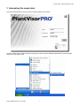
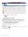
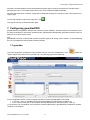
1. Accessing the supervisor
To access PlantVisorPRO Locale, open the following page in the browser:
to do this, select the link called “Supervisor login page” under Program Files/PlantVisorPRO from the Windows
“Supervisor login page” menu:
Code +030220491 rel. 2.1 11/12/06
5
Quick Guide - PlantVisorPRO Locale
1.1. System authentication
To access PlantVisorPRO, type:
User
admin
Password
admin
(only use lower case)
and click “Login” to confirm access:
the following page will be displayed:
Code +030220491 rel. 2.1 11/12/06
6
Quick Guide - PlantVisorPRO Locale
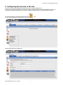
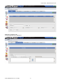
2. Configuring the devices in the site
The site is configured by setting the serial lines and the corresponding devices.
The devices are connected together by data lines; multiple lines are possible in the same installation. Each line is
connected to a different serial port on the computer where the PlantVisorPRO Locale supervisor is installed.
To configure the site, move the mouse arrow to the
icon.
a menu will be displayed; select the item “Site configuration”.
The following page will be displayed:
Code +030220491 rel. 2.1 11/12/06
7
Quick Guide - PlantVisorPRO Locale
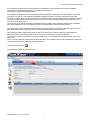
In the “Name” field enter a name that identifies the installation where PlantVisorPRO Locale is installed.
This site will be listed under this name on any Remote supervisors.
(for example: "Supermarket Refrigeration")
The “Identifier” field allows the PlantVisorPRO Remote supervisor to distinguish a local installation from other
local sites. As a result, in the “Identifier” field enter a different number from those used for the other sites.
This field is used together with the password to control access when communicating with PlantVisorPro Remote.
For the connection between the local and remote sites to be successful, the “Identifier” and “Password” must
coincide on both supervisors.
Consequently, enter a different string of characters and/or numbers in the "Identifier" field for each installation.
One useful suggestion is to use the phone number of the site being configured as the identifier.
The “Telephone” field is a useful piece of information when the site is connected to a Remote supervisor via a
dedicated modem. Enter the phone number of the line that the modem is connected to.
The “Password” field is required to protect access to the supervisory system when this is connected to a
dedicated modem. The password is then required to access this site via a remote connection.
The minimum number of characters is 6 and the maximum is 16, and distinction is made between upper and
lower case.
In the “Confirm password” field repeat the same password. The password will only be accepted if the data in the
“Password” and “Confirm password” fields are identical.
To save the settings, click
.
To set the lines, select the "New Line" tab:
Code +030220491 rel. 2.1 11/12/06
8
Quick Guide - PlantVisorPRO Locale
The following page will be opened:
Set :
•
•
•
the serial port on the computer that the converter is connected to (usually COM1) in the “COM port” field,
the transmission speed of the port (usually 19200 baud) in the “Baud rate” field,
the type of communication protocol, which depends on the type of device and the type of serial converter
used, in the “protocol” field.
Note:
the RS485 protocol is used for the PC485KIT00 converter (98C425C001)
the RS485N protocol is used for the PC-Gate serial converter (CVSTD00000) or for the USB converter
(CVSTDUMOR0)
Each line contains devices that must each be set with their own address.
Code +030220491 rel. 2.1 11/12/06
9
Quick Guide - PlantVisorPRO Locale
With reference to the “Devices” section, enter the devices in the serial line: select the first address from the “From
address” list, the last address from the “To address” list, and the type of device entered within such range from the
“Description” list, then click
.
the set configuration will be displayed in the list of devices:
Clicking
saves the settings and returns to the “Site configuration” page.
Code +030220491 rel. 2.1 11/12/06
10
Quick Guide - PlantVisorPRO Locale
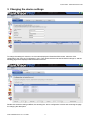
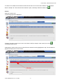
3. Changing the device settings
To change the settings for a device, such as name displayed in PlantVisorPRO remote, select the “Site
configuration” item from the "Configuration" menu. Then double click the line that the device belongs to, and the
following page will be displayed with the details of the line.
Double click the device being modified, thus entering the “device configuration” section and accessing the page
for changing the description.
Code +030220491 rel. 2.1 11/12/06
11
Quick Guide - PlantVisorPRO Locale
In the “Description” section, the descriptions can be changed for each of the various languages installed.
In the “Default description” field, enter the new description in the default language set during installation.
In the “Multilanguage description” tab, enter the corresponding description of the device for the various
languages available.
In the “Status” section, the status of the device can be changed with reference to the supervisor.
The “Disable the device (alarms configured in SCHEDULER section will not be managed)” check box is used to
disable the device for the supervisor, that is, the device will continue to physically operate, but the supervisor will
consider it as being disabled and will not show nor manage any alarms. A typical application of this is when a
refrigeration unit is placed in standby.
Clicking
saves the settings.
Code +030220491 rel. 2.1 11/12/06
12
Quick Guide - PlantVisorPRO Locale
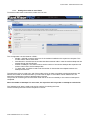
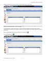
3.1. Changing the activation of the alarms
To change the activation of the alarms, click the “Alarm variables” tab.
The following page will be displayed
The table shows all the alarms managed by the specific device.
The “Frequency for checking the alarms” field is used to decide how often PlantVisorPRO will check whether the
device has at least one active alarm from those selected in the “Active” column. The alarm can be
selected/deselected in this column.
The “Priority” column indicates the priority of the alarm when more than one alarm is active at the same time.
The alarms with “Highest” priority are the first to be managed, while those with the lower priority are placed in the
queue. By default all the alarms have “Highest” priority.
To save the settings, click
Code +030220491 rel. 2.1 11/12/06
13
Quick Guide - PlantVisorPRO Locale
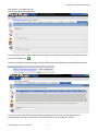
3.2. Changing the activation of the variable log
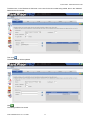
To enable/disable or change the variable log, click the “Variables” tab.
The following page will be displayed:
The log refers to the recording of a series of values of such variables over time.
The “Variable” column indicates the description of the logged variable.
The “HACCP” column, if selected for an item, indicates that that variable will be logged according to the HACCP
standards (EN 12830 “Temperature recorders for the transport, storage and distribution of chilled, frozen, deepfrozen/quick-frozen food and ice cream”).
The variables marked HACCP are automatically logged for more than one year, every 30 minutes.
The “log” column is used to enable the variable log function; once selected this item the columns “Log duration”,
“Minimum Variation” and “Frequency”.
The “Log duration” column allows to select for each variable the log duration. Once occupied all the log space
established by the user, the oldest data are over-written.
Code +030220491 rel. 2.1 11/12/06
14
Quick Guide - PlantVisorPRO Locale
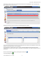
The “Frequency” column allows selecting, for each variable, the time interval in which the supervisor makes the
sampling.
The “Minimum variation” column shows which is the minimum curve definition step in the graph.
To save the setting click
.
Example:
If the variable is set with:
Duration: 1 month
Minimum variation: 0.2
Frequency: 5 minutes
Log start: 19/09/2006 at 11.30
The graph will be the following
Code +030220491 rel. 2.1 11/12/06
15
Quick Guide - PlantVisorPRO Locale
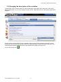
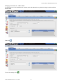
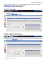
3.3. Changing the description of the variables
The description of the variables relating to a device (description of the parameters, description of the alarms,
names of the probes, etc.) can be changed; to do this, click the “Descriptions List” tab, the following page will be
displayed
The tab contains the descriptions of all the variables. Double clicking an item loads the “Description” section,
allowing the user to change the description both in the default language (“Default description” field) and in any
other languages (“Multilanguage description” tab) installed when setting up the supervisor.
To save the changes click
.
Code +030220491 rel. 2.1 11/12/06
16
Quick Guide - PlantVisorPRO Locale
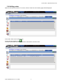
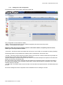
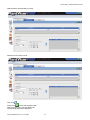
3.4. Adding notes
Notes can be entered for device. To do this, click the “Notes” tab, the following page will be displayed:
In the “Note” field, enter the desired text.
To save the note entered, click
.
The note will be saved with the date and time it was entered, and the author.
Code +030220491 rel. 2.1 11/12/06
17
Quick Guide - PlantVisorPRO Locale
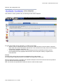
When clicking a note in the list of notes:
and then clicking
the selected note is deleted
saves the changes made.
Clicking
N.B. Only the author has the right to edit or delete their own notes.
3.5. Alarm guardian
This function ensures that all the alarms are acknowledged and failure of the scheduler to signal an alarm is
notified.
Code +030220491 rel. 2.1 11/12/06
18
Quick Guide - PlantVisorPRO Locale
Click the “site configuration” link
Then select the “Alarm guardian” tab; the following window will be displayed
For each level of alarm priority (see Chap. 3.1) there are two fields:
• “Maximum time to manage the alarms”: this function notifies the failure of the scheduler to signal an
alarm within the set time. Remember that this time is not the same as the delay set for each rule when
configuring the scheduler (see Chap. 4.4)
• “Can be acknowledged”: function for acknowledging the alarms with different levels of priority.
Acknowledgement simply highlights that the alarm has formally been read by a registered and
authorised user.
Example:
The high priority alarms have a maximum management time of 180 minutes.
For a certain type of high priority alarm the scheduler is programmed to send a fax.
When the high priority alarm is activated, the scheduler attempts to send a fax but due to technical problems
(e.g. line disconnected) these attempts fail.
After 180 minutes, the guardianPRO notifies the failure to send the alarm signal.
Code +030220491 rel. 2.1 11/12/06
19
Quick Guide - PlantVisorPRO Locale
4. Scheduler
4.1. Configuring the I/O peripherals
PlantVisorPRO, using the scheduler, can monitor the alarms on the installation and, depending on the type of
alarm, the alarm device, the time period and the peripherals available for signalling the alarm, can warn the
users.
The I/O peripherals must be configured to set all the functions that allow PlantVisorPRO to communicate with the
outside world. These are :
- Fax : Set a fax modem for sending any alarms or reports
- SMS : Set a modem (GSM or analogue) for sending any alarms via an SMS message
- E-mail : Set an e-mail address for sending any alarms or reports via e-mail
- RAS : (Remote Access Service) Set a connection to a remote computer
- Window : Set the type of sound that the computer where the PlantVisorPRO supervisor is installed will make
when the alarm window is displayed
- Relay: see the “Full user manual” for configuring the relays
Important note: for Fax, SMS and E-mail, using the
button on these pages, an action can be created for
sending the schedule alarm, via the peripheral, to all the numbers or addresses set in the address book.
Example :
If the fax modem has two numbers in the address book, pressing
creates the “Fax-Action” in the scheduler,
meaning the alarm fax will be sent via the modem to these 2 numbers.
To set the configuration of the supervisor Input/Output peripherals, select the item "I/O configuration" from the
"Scheduler" menu
The following page will be displayed:
Code +030220491 rel. 2.1 11/12/06
20
Quick Guide - PlantVisorPRO Locale
4.1.1. Setting the modem to send faxes
To set the modem used to send faxes, select the "Fax" tab:
The “Configuration” section features 3 fields :
• Modem : this field is used to select one of the modems installed on the supervisor computer. This
modem will be used to send faxes.
• Switchboard: in this field set the number that allows external calls in case the modem telephone line
passes through the switchboard.
• Number of attempts : this field is used to set the number of successive attempts the supervisor will
make to send a fax if the first attempt fails.
• Try again after : this field is used to set the number of minutes that must elapse between one
attempt and the next.
The supervisor will try to send a fax, and if the modem is busy or there are problems during transmission, will
wait the set number of minutes and then try to send the fax again. If the modem cannot send the fax, the
supervisor will make the number of attempts set by the user.
The process for resending the fax ends either when the fax is sent successfully or the number of attempts is
completed.
Note: the number of attempts if is set to zero, the supervisor will only make on attempt to send the fax.
The "Address book" area is used to set the fax numbers for sending the faxes.
The fax will always be sent to all the recipients on the list.
Code +030220491 rel. 2.1 11/12/06
21
Quick Guide - PlantVisorPRO Locale
To add an item, in the "Reference" field enter a cue name for the fax number being added, then in the "Address"
field enter the fax number.
.
Then click
The address book will be updated.
.
Click
The settings will then be saved.
Code +030220491 rel. 2.1 11/12/06
22
Quick Guide - PlantVisorPRO Locale
Changing an item in the fax "Address book"
To change an item in the “Address book” section, select the desired item by double clicking it and then edit the
desired fields.
Then click
.
To save the settings, click
.
Code +030220491 rel. 2.1 11/12/06
23
Quick Guide - PlantVisorPRO Locale
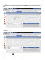
4.1.2. Setting the modem to send SMS messages
To set the modem used for sending SMS messages, select the "SMS" tab:
The “Configuration” section features 6 fields :
•
•
•
•
•
•
•
Modem : this field is used to select one of the modems (analogue or GSM) installed on the
supervisor computer. This modem will be used to send the SMS messages.
Switchboard: in this field set the number that allows external calls in case the modem telephone line
passes through the switchboard.
Type : this field is used to set the type ("Analogue" or "GSM") of modem that is selected in the
“modem” field.
Provider : this field is used to select the provider used to send the SMS messages. If a GSM modem
is used, select “Direct SMS xxx” where xxx is the model of GSM modem supported. Currently the
following are supported: Falcom Twist, Siemens T35, Wavecom
Call : select whether or not the call is international ("National" or "International")
Number of attempts : this field is used to set the number of successive attempts the supervisor will
make when sending an SMS if the first attempt fails.
N.B. This function is only valid for managing the calls made by the analogue modem to the service
provider or for checking the availability of the analogue / GSM modem, as the effective delivery to
destination of the SMS message cannot be checked.
Try again after : This field is used to set the number of minutes that must elapse between one failed
attempt and the next.
Once all the settings have been completed add the numbers to the address book for sending the SMS
messages.
The "Address book" area is used to set the numbers that the supervisor will use to send the SMS messages, in
the same was as for the faxes.
To save the settings, click
.
Code +030220491 rel. 2.1 11/12/06
24
Quick Guide - PlantVisorPRO Locale
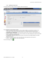
4.1.3.
Setting the e-mail configuration
To set the data used to send e-mails, select the "E-Mail" tab:
The “Configuration” section features 6 fields :
- SMTP : Name of the mail server or the IP address supplied by the Internet service provider
- Sender : e-mail address of the sender.
Important: some mail service providers require a valid sender address, accepted by the mail server;
contact your service provider for details.
- Connection : this field is used to set whether the mail server is in the LAN or is accessed via modem ("DialUp")
The following fields are only enabled if the "DialUp" option is selected the "Connection" field.
- Provider : this field is used to select the provider used for the connection. This list includes all the providers set
in the Windows “Control panel” under “Network connections”.
- Number of attempts: This field is used to set the number of successive attempts the supervisor will make when
sending an email if the first attempt fails.
N.B. This function is only valid for managing the calls made by the analogue modem to the service provider or
for checking the availability of the analogue / GSM modem, as the effective delivery to destination of the SMS
message cannot be checked.
- Try again after: This field is used to set the number of minutes that must elapse between one failed attempt and
the next.
Once all the settings have been completed, enter the address book for sending the e-mails.
Code +030220491 rel. 2.1 11/12/06
25
Quick Guide - PlantVisorPRO Locale
To add an item, in the "Reference" field enter a cue name for the recipient being added, then enter the e-mail
address in the "Address" field.
.
Then click
The address book will be updated.
To save the settings, click
.
Code +030220491 rel. 2.1 11/12/06
26
Quick Guide - PlantVisorPRO Locale
Changing an item in the e-mail "Address book"
To change an item in the "Address book", select the desired item by double clicking it and then edit the desired
fields.
Then click
.
To save the settings, click
.
Code +030220491 rel. 2.1 11/12/06
27
Quick Guide - PlantVisorPRO Locale
4.1.4.
Setting the remote calls
To set the possibility of calling a remote computer, select the "RAS" tab:
The “Configuration” section features 6 fields:
• Modem : this field is used to select one of the modems installed on the supervisor computer. This
modem will be used to make remote calls (connection to a PlantVisorPRO Remote supervisor).
• Switchboard: in this field set the number that allows external calls in case the modem telephone line
passes through the switchboard.
• Number of attempts: This field is used to set the number of successive attempts the supervisor will make
when contacting the remote supervisor.
• Try again after: This field is used to set the number of minutes that must elapse between one failed
attempt and the next.
• Reference : Identifying name of the remote site that the local supervisor must connect to.
• Number : Telephone number of the remote supervisor.
To save the settings, click
.
Code +030220491 rel. 2.1 11/12/06
28
Quick Guide - PlantVisorPRO Locale
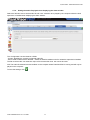
4.1.5.
Setting the audio file played when displaying the alarm window
Select the "Window" tab to set the audio file with “wav” extension to be played by the computer where the local
supervisor is installed when displaying the alarm window.
The “Configuration” section features 2 fields:
- Current: identifies the currently configured audio file;
- Sound: used to select with the "Browse..." button an audio file resident on the PC where the supervisor is installed.
The file must have the .wav extension. Mp3 or file formats other than .wav cannot be used.
N.B. The audio file selected must be resident on the computer where PlantVisorPRO is running and will only be
played on this computer.
To save the settings, click
.
Code +030220491 rel. 2.1 11/12/06
29
Quick Guide - PlantVisorPRO Locale
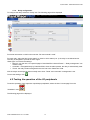
4.1.6. Relay configuration
To configure the relays select the “Relay” tab. The following page will be displayed
For further information on this function see the “Full user manual Locale”
For each relay, select the field “Active status” to chose in which status (0 or 1) the relay is considered active.
The relay is energised to provide an alarm signal.
“Reset type” can have three settings:
• Manual : only the user, via a special page in PlantVisorPRO “Alarms/Events” – “Relay management” can
reset the relay
• Automatic : managed directly by PlantVisorPRO; when the alarm passes, the relay is automatically reset
• Timed : the relay remains energised for the time set in the “Reset time” field.
N.B. the relays can always be reset manually even when “Timed” and “Automatic” management is set.
To save the settings, click
.
4.2. Testing the operation of the I/O peripherals
To test the operation of the supervisor Input/Output peripherals, select the item "I/O test page" from the
"Scheduler" menu
The following page will be displayed
Code +030220491 rel. 2.1 11/12/06
30
Quick Guide - PlantVisorPRO Locale
•
•
In the “Action type” section, select the I/O peripheral to be tested
Select the recipient
•
Click
.
The I/O peripheral will be activated so as to test its operation.
4.3. Managing the alarms and events
After having configured all the I/O peripherals, the list of alarms managed by the scheduler needs to be set. By
default, a list is included with all the alarms for all the instruments. Below are the instructions on using this
default setting. See the “Full user manual” for the instruction on how to set different lists of alarms.
The scheduler is made up of a set of “Rules” that are continuously checked and updated. A rule includes:
a) a list of alarm conditions (alarms) deriving from the field devices
b) a series of time bands that determine the periods when the alarm is valid
c) a series of actions for signalling the alarm to the outside world
Before defining a “Rule”, therefore, first its components need to be defined.
To signal all the alarms, proceed as follows.
Alarm condition
Configure the management of alarms and events in the supervisor, selecting the “Alarm and event management”
item from the “Scheduler” menu
The following page will be displayed:
Code +030220491 rel. 2.1 11/12/06
31
Quick Guide - PlantVisorPRO Locale
Select the “Conditions” tab.
The following page will be displayed:
Code +030220491 rel. 2.1 11/12/06
32
Quick Guide - PlantVisorPRO Locale
To create a new condition for the alarms on all the devices, enter a cue name for the condition in the “Description”
field, for example “All”. Then select the “All the devices” option, and finally to add the condition click
.
Actions
Select the “Actions” tab
The following page will be displayed:
To add a new action, enter the cue name in the “Name” field (for example: “Alarm action”) then click
The settings will be saved.
Subsequently, double click the new row that has been entered in the list (highlighted in red). This will allow the
peripherals used to be set for this action.
Code +030220491 rel. 2.1 11/12/06
33
Quick Guide - PlantVisorPRO Locale
Double click the red row in the list of actions and the following page will be opened.
Assuming the desired actions are to send a fax and display the alarm window (for the explanation of all the other
settings, see the PlantVisorPRO “Full User Manual”).
The “Address book - numbers” tab in the “Fax” section contains the address book that has been set when
configuring the fax modem (see the chapter “Configuring the I/O peripherals”, sub-chapter “Setting the modem to
send faxes”).
Add the desired address book items by selecting them and then click
To save the settings, click
Code +030220491 rel. 2.1 11/12/06
34
.
Quick Guide - PlantVisorPRO Locale
Then select the “Print/Window” tab
The following page will be displayed:
To set the alarm window, check the item corresponding to “Enable the alarm window” in the “Window” section.
To save the settings, click
To return to the page for setting the actions, click the “Alarms and events management” link located above the tab:
.
The row in the list of the actions that was previously highlighted is no longer red and shows the ticks
corresponding of the types of action set, in this example in the “Fax” and “Window” columns.
Code +030220491 rel. 2.1 11/12/06
35
Quick Guide - PlantVisorPRO Locale
Rules
Now select the “Rules” tab.
The following page will be displayed:
In the “Rules” section, enter a cue name in the “Description” field for the rules being created (for example:
“General rules”).
Then select the previously created condition to be used (for example: “All”).
Select the time band (for example: “Always”).
N.B. the “Always” time band is the default, and this therefore does not need to be set in the “Time bands” section.
Select the action (for example: “Alarm action”).
Enter the delay, in minutes, for the implementation of the rules in response to an alarm.
click
.
The settings will then be saved.
The following page will be displayed:
The “Enabled” field is used to enable or disable a certain rule, if the field is checked the rule will be enabled for the
supervisor.
Code +030220491 rel. 2.1 11/12/06
36
Quick Guide - PlantVisorPRO Locale
4.4. Managing the scheduled activities
The PlantVisorPRO scheduler not only ensures alarm management, but also allows a number of actions to be
performed at certain times.
To set a scheduled activity in the supervisor, proceed as follows.
Select the item “Scheduled activities management” from the “Scheduler” menu
The following page will be displayed:
Select the “Actions” tab
The following page will be displayed:
To add a new action, enter the cue name in the “Name” field (for example: “Alarm action”), click
The settings will then be saved.
Code +030220491 rel. 2.1 11/12/06
37
.
Quick Guide - PlantVisorPRO Locale
Subsequently double click the new row that has been entered in the list (highlighted in red). This will allow the
type of operation to be set for this action.
Double click the red row in the list of actions, the following page will be opened:
Assuming the desired actions are to send a fax and display the alarm window (for the explanation of all the other
settings, see the PlantVisorPRO “Full User Manual”).
The “Address book - numbers” tab in the “Fax” section contains the address book that has been set when
configuring the fax modem (see the chapter “Configuring the I/O peripherals”, sub-chapter “Setting the modem to
send faxes”).
Enter the desired address book items by selecting them and then click
To save the settings, click
Code +030220491 rel. 2.1 11/12/06
38
.
Quick Guide - PlantVisorPRO Locale
To return to the page for setting the actions, click the “Scheduled activities management” link above the tabs.
Then select the “Time bands” tab
The following page will be displayed:
Enter the text “Workdays” in the “Description” field.
From the “Type” selection field, select the item “Weekly”.
Code +030220491 rel. 2.1 11/12/06
39
Quick Guide - PlantVisorPRO Locale
Select the days from Monday to Friday:
Set the time from 8:00 to 9:00:
Then click
.
Finally click
to save the changes made.
Now to set the rules, click the “Rules” tab
The following page will be displayed:
Code +030220491 rel. 2.1 11/12/06
40
Quick Guide - PlantVisorPRO Locale
In the “Rules” section, enter a cue name in the “Description” field for the rule being created (for example: “Weekly fax”).
Check the “Enabled” field.
Select the desired time band (for example: “Workday”)
Select the action you want to set (for example: “Alarm action”).
Click
.
The settings will then be saved and become operational.
Code +030220491 rel. 2.1 11/12/06
41
Quick Guide - PlantVisorPRO Locale
5. Groups and Areas (if included in the version)
Groups are logical groupings of devices.
These are displayed in the form of lists in the menu with the icon
Groups are useful for identifying
• a set of devices with the same features (e.g. all IRmpx)
• a set of devices with the same type of product stored (e.g.: “dairy showcases”, “fruit and vegetables”,
“frozen food”)
The advantages of using groups derive from the immediateness of the information displayed and the possibility
to create different types of management for each group.
With the groups is possible create variables of group.
Areas are logical groupings of groups and/or of devices.
These are displayed in the bar at the top.
If supervising a refrigeration installation in a supermarket, areas can be created to identify similar devices and/or
groups. For example, the low temperature and the normal temperature devices can be grouped together (“dairy
showcases”, “fruit and vegetables”, “frozen foods”), the groups can be added, depending on the type, to an area:
“LT utilities” or “NT utilities”.
For further information and how to configure these, see the chapters on “Groups” and “Areas” in the
PlantVisorPRO Full User Manual.
6. Registering the product
To register the product, from the “Configuration” menu
page will be displayed :
select the “System pages” item; the following
On the www.carel.com site click the “Request PlantVisorPRO activation code” link, complete all the fields on the
application form.
Code +030220491 rel. 2.1 11/12/06
42
Quick Guide - PlantVisorPRO Locale
Important: The MAC-address on the PlantVisorPRO system page is required, as well as the “Serial Number”
printed on the CD or on the label at the bottom in the case of PlantVisorPRO Embedded.
Once the data have been confirmed, a page will be displayed showing the “activation code” to be entered in the
system page.
To save the activation code for the supervisor, click
.
Then logout and login to PlantVisorPRO again.
7. Configuring guardianPRO
guardianPRO is an application that ensures maximum system reliability. All the processes are monitored, and in
the event of hardware or supervision software faults, guardianPRO independently generates an alarm signal via
SMS, fax or e-mail to warn the user.
N.B.
guardianPRO must be configured with at least one alarm signal, even simply “Alarm window”, to avoid restarting
the unit if guardianPRO cannot signal the alarm situation.
7.1. guardian
To access the general configuration of the guardian function, from the “Configuration” menu
“System pages” item and then the “guardian” tab; the following page will be displayed:
select the
In the Configuration section, set the computer and the port where guardianPRO is connected:
• Computer : name or IP address where the guardianPRO is installed (leave “localhost”)(*)
• Port : number of the port on the computer where guardianPRO is connected (leave “1974”)(*)
(*) Consult the “Full User Manual” and contact the network administrator if guardianPRO is installed on another
computer in the network.
Code +030220491 rel. 2.1 11/12/06
43
Quick Guide - PlantVisorPRO Locale
In the “Variables configuration” section, a number of device probes can be selected that guardianPRO monitors
independently of PlantVisorPRO. This monitoring process makes sure that reliable values are always received
from the field devices.
1. Choose the device with the variable to be managed by guardian from the “Device” list box
2. From the “Variables available”, select the variables to be monitored by guardian
3. Click
to add these to the “Monitored variables” list
4.
5.
6.
7.
To remove a controlled variable from the list, select it and click
Repeat this procedure from point 1 to point 3 for each group of variables on the devices being monitored
Set how often to activate the guardian (in minutes) in the “Monitoring frequency (min.)” field
Set the “Monitoring frequency” and “Number of constant consecutive values to signal an error”, that is,
the for how long the probes have a constant value before assuming a communication error with the field
devices.
For a minimum configuration select at least one probe on 2 / 3 different instruments and leave the two preset
values at 10.
Once the settings have been completed, click
Then select the “Signals” tab.
to save the configuration.
7.2. Signals
Once having selected the “Signals” tab, the following page will be displayed:
The address book will include all the recipients of the signals from the scheduler. One or more recipients in the
address book can be used, or alternatively, again in the “Configuring the I/O peripherals” pages, a specific
recipient can be entered for the signals from the guardian. If a Scheduler address book entry is removed, this
event will not affect the list in guardianPRO, which is managed separately.
From the “Address book” list, select the addresses or the numbers to send the guardianPRO signals to, then
click
to add these to the “List of signals”
In the event of an error when entering, select the incorrect item in the “List of signals” and click
To save the settings, click
Code +030220491 rel. 2.1 11/12/06
44
Quick Guide - PlantVisorPRO Locale
8. Glossary
Active alarm: Active alarms are alarms whose causes are still present.
Alarm: Alarms are status signals sent by the devices to the supervisory system and then processed to indicate
abnormal situations or faults.
Alarm report: The alarm report is a table that, based on a start and end date set by the user, displays all the
alarms that have occurred over a set period.
Area: Logical set of groups and/or devices.
Daily report: The daily report is a table that displays the values of certain logged variables selected by the user
for a specific date.
Device: Device refers to an electronic device connected to a supervisory network that can be managed by
PlantVisorPRO.
Event: Events are sets of information sent by the devices, I/O peripherals, or generated by the supervisor. This
information communicates the general operating status of the supervisor.
Group: Logical set of devices. Group variables can be created for the groups.
Group variable: logical extension of variables with write access that belong to different devices that have been
entered in the same group.
Instant value report: The instant value report is a table that displays the instant values (those measured at the
moment of printing the report) of the variables for a certain device.
Local supervisor: A local supervisor is a system for controlling and managing devices.
Log report: The alarm log report is a table that, based on a start and end date set by the user, displays the
values of certain logged variables selected by the user.
Network: A network is a series of devices connected to and supervised by PlantVisorPRO (devices, converters,
etc. ).
Remote supervisor: A remote supervisor is a centralised system for controlling the local supervisors.
Report: Reports are tables generated according to time that contain the data of the logged variables.
Reset alarm: Reset alarms are alarm events whose causes are no longer present.
Site: A site is any installation managed by PlantVisorPRO. Normally the name of the site is used to indicate a
PlantVisorPRO installation that is accessible via a remote connection.
Supervisor: Program that can manage the hardware connected to the computer. Its main task is to check the
status of the devices and implement actions according to the rules set by the user, keeping trace of such actions.
User: A user is a subject who is approved and authorised to access the supervisor.
Variable: Each device has a number of variables, which are configuration parameters and/or status conditions of
the device.
Code +030220491 rel. 2.1 11/12/06
45
CAREL S.p.A.
Via dell’Industria, 11 - 35020 Brugine - Padova (Italy)
Tel. (+39) 049.9716611 Fax (+39) 049.9716600
http://www.carel.com - e-mail: [email protected]
Code +030220491 rel. 2.1 dated 11/12/06
Agenzia / Agency: