1
II
Trademarks
All brand names and product names used in this Product Guide are trade names, service marks, trademarks, or registered trademarks of
their respective owners.
B
169 / BB072001.SAM
/0720-01/0100
III
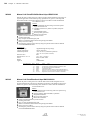
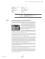
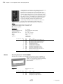
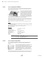
Introduction
Supported by the quality management system certified according to ISO9001, our products
are developed, manufactured and accurately tested in accordance to national and international
standards as well as to our own strict regulations.
The planning of systems as well as the installation, commissioning and maintenance of the
products and of the systems combined thereof require specific expert knowledge and therefore may only be made by trained expert personnel. The product-specific training of the expert
personnel must be made by LST or by persons explicitly authorized by LST. All valid country
specific regulations and guidelines for the use of the products must be obeyed. This Product
Guide is under no circumstances a substitute for the detailed documentation of the individual
products or for the product-specific training of the expert personnel on proper and professional installation, connection, programming and operation of our products and of systems combined thereof.
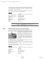
This Product Guide contains general information on the use for each product. Descriptions,
pictures and specifications correspond to the conditions and intentions at the time of printing
of the Product Guide. We reserve the right for modifications of any type, especially when on
account of technological progress and do not take on any liability for misprints and obvious
mistakes. The values stated in the specifications generally represent nominal values; by means of sample variations, product modifications or site specific conditions, these values may
differ from the actually measured values.
LST always tries to provide information as comprehensive and as accurate as possible. Nevertheless, all information on suitability and use of our products are non-binding and do not
liberate the introducer in a market from doing own tests. The buyer is responsible for himself
for obeying legal and official regulations in connection with the use.
With the publication of this Product Guide, all previous Product Guides and, if prices are contained in this Product Guide, all previous price lists of the corresponding subject and sales
area lose their validity. The charge for the products is made on basis of the prices valid on the
day of delivery. All delivery contracts are concluded on the basis of the "General Terms of
Delivery issued by the Austrian Electrical and Electronics Association".
Special delivery times or export limitations may exist for some products listed in the Product
Guide. Also country specific variants of products may be listed in the Product Guide which
may not be used in all sales areas due to different technical requirements or specific approval
limitations.
Please always refer to the article number of the products when making an inquiry or when
placing an order.
169 / BB072001.SAM
/0720-01/0100
B
IV
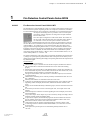
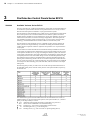
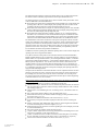
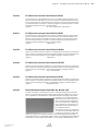
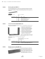
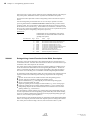
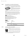
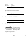
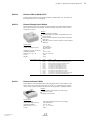
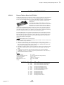
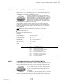
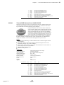
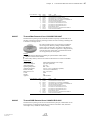
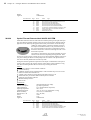
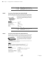
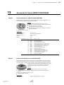
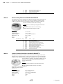
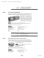
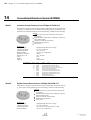
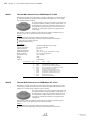
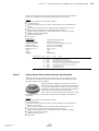
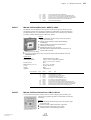
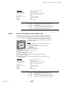
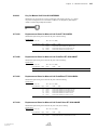
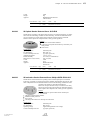
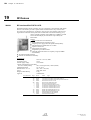
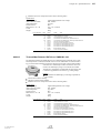
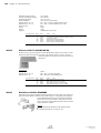
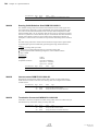
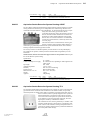
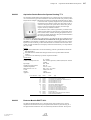
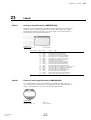
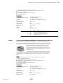
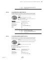
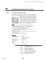
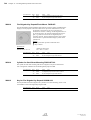
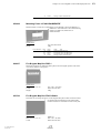
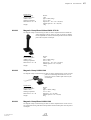
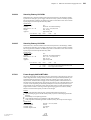
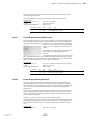
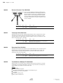
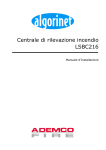
Example of an article entry
1
999999
5
2
3
4
Name Type
xx.xxx,xx
Description of the article with basic notes on function,
design, application, detailed specifications,
approval codes and other information.
6
Cross-references
Page
xx
xx
xx
xx
Art.Nr.
999999
888888
777777
666666
Name Type
Name Type
Name Type
Name Type
Name Type
xx.xxx,xx
xx.xxx,xx
xx.xxx,xx
xx.xxx,xx
1 . . Article number; please always refer to this number on inqiries or orders to avoid
mistakes.
2 . . Product name
3 . . Type; the type is a string of alpha-numerical characters and symbols without blank characters and is separated from the product name by one blank character.
4 . . Price per unit (generally per piece)
5 . . Product description, details on approvals and examinations, specifications
6 . . Cross-references to other products of the Product Guide which are in direct connection
with the chosen product. These cross-references present a list of possibilities which are
of exemplary nature only; the products listed therein must not necessarily be working
altogether.
B
169 / BB072001.SAM
/0720-01/0100
V
Contents
1
Fire Detection Control Panels Series BC06
210205
210200
210204
210209
210208
210210
210215
210212
2
Fire Detection Control Panels Series BC016
210102
210100
210122
210120
210110
210111
210112
3
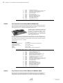
Fire Detection Control Panel BC016-1/INT1 . . . . . . . . . . . . . . . . . . . . . . . . . . . . . . . . . . . . . . . . . . . . . . . . . . . . . . . . . 6
Fire Detection Control Panel BC016-1/D1 . . . . . . . . . . . . . . . . . . . . . . . . . . . . . . . . . . . . . . . . . . . . . . . . . . . . . . . . . . . . 7
Fire and Evacuation Panel BC016-2/INT1 . . . . . . . . . . . . . . . . . . . . . . . . . . . . . . . . . . . . . . . . . . . . . . . . . . . . . . . . . . . . 7
Fire and Evacuation Panel BC016-2/D1 . . . . . . . . . . . . . . . . . . . . . . . . . . . . . . . . . . . . . . . . . . . . . . . . . . . . . . . . . . . . . . 8
Detector Zone Extension MGE8-1 . . . . . . . . . . . . . . . . . . . . . . . . . . . . . . . . . . . . . . . . . . . . . . . . . . . . . . . . . . . . . . . . . . . 8
Fire Brigade Interface FWI016-1 . . . . . . . . . . . . . . . . . . . . . . . . . . . . . . . . . . . . . . . . . . . . . . . . . . . . . . . . . . . . . . . . . . . . . 9
Serial Interface Module SIM016-3 . . . . . . . . . . . . . . . . . . . . . . . . . . . . . . . . . . . . . . . . . . . . . . . . . . . . . . . . . . . . . . . . . . . . 9
Fire Detection Control Panels Series BC216
2149999
214008
214000
214610
214006
214015
214007
214009
214017
214049
214080
214084
214086
214088
214308
214300
214304
214306
214315
214307
214309
214317
214349
214384
214388
2199998
214056
214004
214612
214060
214064
214062
214058
214066
169 / BB072001.SAM
/0720-01/0100
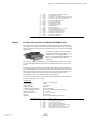
Fire Detection Control Panel BC06-1/INT1 . . . . . . . . . . . . . . . . . . . . . . . . . . . . . . . . . . . . . . . . . . . . . . . . . . . . . . . . . . . 1
Fire Detection Control Panel BC06-1/D1 . . . . . . . . . . . . . . . . . . . . . . . . . . . . . . . . . . . . . . . . . . . . . . . . . . . . . . . . . . . . . 2
Fire Detection Control Panel BC06-1A/D1 . . . . . . . . . . . . . . . . . . . . . . . . . . . . . . . . . . . . . . . . . . . . . . . . . . . . . . . . . . . 2
Fire Detection Control Panel BC06-2/INT1 . . . . . . . . . . . . . . . . . . . . . . . . . . . . . . . . . . . . . . . . . . . . . . . . . . . . . . . . . . . 3
Fire Detection Control Panel BC06-2/D1 . . . . . . . . . . . . . . . . . . . . . . . . . . . . . . . . . . . . . . . . . . . . . . . . . . . . . . . . . . . . . 3
Zone Extension Board ZEB2-1 . . . . . . . . . . . . . . . . . . . . . . . . . . . . . . . . . . . . . . . . . . . . . . . . . . . . . . . . . . . . . . . . . . . . . . . 4
Serial Interface Module SIM06-1 . . . . . . . . . . . . . . . . . . . . . . . . . . . . . . . . . . . . . . . . . . . . . . . . . . . . . . . . . . . . . . . . . . . . . 4
Front Foil for Evacuation Circuit FFEV06-1 . . . . . . . . . . . . . . . . . . . . . . . . . . . . . . . . . . . . . . . . . . . . . . . . . . . . . . . . . . 5
Available Variants Series BC216 . . . . . . . . . . . . . . . . . . . . . . . . . . . . . . . . . . . . . . . . . . . . . . . . . . . . . . . . . . . . . . . . . . .
Fire Detection Control Panel BC216-1/INT1 . . . . . . . . . . . . . . . . . . . . . . . . . . . . . . . . . . . . . . . . . . . . . . . . . . . . . . .
Fire Detection Control Panel BC216-1/A1 . . . . . . . . . . . . . . . . . . . . . . . . . . . . . . . . . . . . . . . . . . . . . . . . . . . . . . . . . .
Fire Detection Control Panel BC216-1/D1 . . . . . . . . . . . . . . . . . . . . . . . . . . . . . . . . . . . . . . . . . . . . . . . . . . . . . . . . . .
Fire Detection Control Panel BC216-1/B1 . . . . . . . . . . . . . . . . . . . . . . . . . . . . . . . . . . . . . . . . . . . . . . . . . . . . . . . . . .
Fire Detection Control Panel BC216-1/CZ1 . . . . . . . . . . . . . . . . . . . . . . . . . . . . . . . . . . . . . . . . . . . . . . . . . . . . . . . .
Fire Detection Control Panel BC216-1/H1 . . . . . . . . . . . . . . . . . . . . . . . . . . . . . . . . . . . . . . . . . . . . . . . . . . . . . . . . . .
Fire Detection Control Panel BC216-1/NL1 . . . . . . . . . . . . . . . . . . . . . . . . . . . . . . . . . . . . . . . . . . . . . . . . . . . . . . . .
Fire Detection Control Panel BC216-1/SK1 . . . . . . . . . . . . . . . . . . . . . . . . . . . . . . . . . . . . . . . . . . . . . . . . . . . . . . . .
Fire Detection Control Panel BC216-1/HR1 . . . . . . . . . . . . . . . . . . . . . . . . . . . . . . . . . . . . . . . . . . . . . . . . . . . . . . . .
Fire Detection Control Panel BC216-1/RUS1 . . . . . . . . . . . . . . . . . . . . . . . . . . . . . . . . . . . . . . . . . . . . . . . . . . . . . . .
Fire Detection Control Panel BC216-1/SLO1 . . . . . . . . . . . . . . . . . . . . . . . . . . . . . . . . . . . . . . . . . . . . . . . . . . . . . . .
Fire Detection Control Panel BC216-1/I1 . . . . . . . . . . . . . . . . . . . . . . . . . . . . . . . . . . . . . . . . . . . . . . . . . . . . . . . . . . .
Fire Detection Control Panel BC216-1/PL1 . . . . . . . . . . . . . . . . . . . . . . . . . . . . . . . . . . . . . . . . . . . . . . . . . . . . . . . . .
Fire Detection Control Panel BC216-1S/INT1 . . . . . . . . . . . . . . . . . . . . . . . . . . . . . . . . . . . . . . . . . . . . . . . . . . . . . .
Fire Detection Control Panel BC216-1S/A1 . . . . . . . . . . . . . . . . . . . . . . . . . . . . . . . . . . . . . . . . . . . . . . . . . . . . . . . .
Fire Detection Control Panel BC216-1S/D1 . . . . . . . . . . . . . . . . . . . . . . . . . . . . . . . . . . . . . . . . . . . . . . . . . . . . . . . .
Fire Detection Control Panel BC216-1S/B1 . . . . . . . . . . . . . . . . . . . . . . . . . . . . . . . . . . . . . . . . . . . . . . . . . . . . . . . .
Fire Detection Control Panel BC216-1S/CZ1 . . . . . . . . . . . . . . . . . . . . . . . . . . . . . . . . . . . . . . . . . . . . . . . . . . . . . . .
Fire Detection Control Panel BC216-1S/H1 . . . . . . . . . . . . . . . . . . . . . . . . . . . . . . . . . . . . . . . . . . . . . . . . . . . . . . . .
Fire Detection Control Panel BC216-1S/NL1 . . . . . . . . . . . . . . . . . . . . . . . . . . . . . . . . . . . . . . . . . . . . . . . . . . . . . . .
Fire Detection Control Panel BC216-1S/SK1 . . . . . . . . . . . . . . . . . . . . . . . . . . . . . . . . . . . . . . . . . . . . . . . . . . . . . . .
Fire Detection Control Panel BC216-1S/HR1 . . . . . . . . . . . . . . . . . . . . . . . . . . . . . . . . . . . . . . . . . . . . . . . . . . . . . . .
Fire Detection Control Panel BC216-1S/SLO1 . . . . . . . . . . . . . . . . . . . . . . . . . . . . . . . . . . . . . . . . . . . . . . . . . . . . .
Fire Detection Control Panel BC216-1S/PL1 . . . . . . . . . . . . . . . . . . . . . . . . . . . . . . . . . . . . . . . . . . . . . . . . . . . . . . .
Fire Detection Control Panel BCnet216, Description . . . . . . . . . . . . . . . . . . . . . . . . . . . . . . . . . . . . . . . . . . . . . . . .
BCnet Sectional Control Panel/OP. BC216-2/INT1 . . . . . . . . . . . . . . . . . . . . . . . . . . . . . . . . . . . . . . . . . . . . . . . . .
BCnet Sectional Control Panel/OP. BC216-2/A1 . . . . . . . . . . . . . . . . . . . . . . . . . . . . . . . . . . . . . . . . . . . . . . . . . . .
BCnet Sectional Control Panel/OP. BC216-2/D1 . . . . . . . . . . . . . . . . . . . . . . . . . . . . . . . . . . . . . . . . . . . . . . . . . . .
BCnet Sectional Control Panel/OP. BC216-2/B1 . . . . . . . . . . . . . . . . . . . . . . . . . . . . . . . . . . . . . . . . . . . . . . . . . . .
BCnet Sectional Control Panel/OP. BC216-2/CZ1 . . . . . . . . . . . . . . . . . . . . . . . . . . . . . . . . . . . . . . . . . . . . . . . . . .
BCnet Sectional Control Panel/OP. BC216-2/H1 . . . . . . . . . . . . . . . . . . . . . . . . . . . . . . . . . . . . . . . . . . . . . . . . . . .
BCnet Sectional Control Panel/OP. BC216-2/NL1 . . . . . . . . . . . . . . . . . . . . . . . . . . . . . . . . . . . . . . . . . . . . . . . . .
BCnet Sectional Control Panel/OP. BC216-2/SK1 . . . . . . . . . . . . . . . . . . . . . . . . . . . . . . . . . . . . . . . . . . . . . . . . . .
B
10
12
14
14
14
14
15
15
15
15
15
15
15
15
16
18
18
18
18
18
18
19
19
19
19
20
23
24
24
24
24
24
25
25
VI
214079
214081
214085
214087
214089
214005
214034
214108
214100
214611
214158
214164
214109
214105
2149997
214204
214205
214234
214208
214200
214615
214209
214020
214021
214022
214023
214024
214030
214032
214036
214031
214003
214130
214232
214028
214128
214029
214230
212034
212030
212029
212033
214129
212031
227009
214601
212027
212028
212032
4
25
25
25
25
25
25
26
27
29
29
29
29
29
29
30
31
32
32
33
34
34
34
35
35
36
37
37
38
38
39
39
40
40
41
41
41
42
42
42
43
43
43
44
44
44
45
45
46
46
Extinguishing System Controls
2189990
218024
2189991
210216
222011
223009
5
BCnet Sectional Control Panel/OP. BC216-2/HR1 . . . . . . . . . . . . . . . . . . . . . . . . . . . . . . . . . . . . . . . . . . . . . . . . .
BCnet Sectional Control Panel/OP. BC216-2/RUS1 . . . . . . . . . . . . . . . . . . . . . . . . . . . . . . . . . . . . . . . . . . . . . . . .
BCnet Sectional Control Panel/OP. BC216-2/SLO1 . . . . . . . . . . . . . . . . . . . . . . . . . . . . . . . . . . . . . . . . . . . . . . . .
BCnet Sectional Control Panel/OP. BC216-2/I1 . . . . . . . . . . . . . . . . . . . . . . . . . . . . . . . . . . . . . . . . . . . . . . . . . . . .
BCnet Sectional Control Panel/OP. BC216-2/PL1 . . . . . . . . . . . . . . . . . . . . . . . . . . . . . . . . . . . . . . . . . . . . . . . . . .
BCnet Sectional Control Panel/No Operation BC216-3 . . . . . . . . . . . . . . . . . . . . . . . . . . . . . . . . . . . . . . . . . . . . .
BCnet Sectional Control Panel/Extension BCE216-3LG . . . . . . . . . . . . . . . . . . . . . . . . . . . . . . . . . . . . . . . . . . . .
Fire Detection Control Panel BC216-1CE/INT1 . . . . . . . . . . . . . . . . . . . . . . . . . . . . . . . . . . . . . . . . . . . . . . . . . . . .
Fire Detection Control Panel BC216-1CE/A1 . . . . . . . . . . . . . . . . . . . . . . . . . . . . . . . . . . . . . . . . . . . . . . . . . . . . . .
Fire Detection Control Panel BC216-1CE/D1 . . . . . . . . . . . . . . . . . . . . . . . . . . . . . . . . . . . . . . . . . . . . . . . . . . . . . .
Fire Detection Control Panel BC216-1CE/NL1 . . . . . . . . . . . . . . . . . . . . . . . . . . . . . . . . . . . . . . . . . . . . . . . . . . . . .
Fire Detection Control Panel BC216-1CE/CZ1 . . . . . . . . . . . . . . . . . . . . . . . . . . . . . . . . . . . . . . . . . . . . . . . . . . . . .
Fire Detection Control Panel BC216-1CE/H1 . . . . . . . . . . . . . . . . . . . . . . . . . . . . . . . . . . . . . . . . . . . . . . . . . . . . . .
BCnet Sectional Control Panel/No Op. BC216-3CE . . . . . . . . . . . . . . . . . . . . . . . . . . . . . . . . . . . . . . . . . . . . . . . .
BCnet Sectional Control Panel/OP. BC216-2EPS . . . . . . . . . . . . . . . . . . . . . . . . . . . . . . . . . . . . . . . . . . . . . . . . . .
Fire Detection Control Panel Module/PS BCM216-3EPS . . . . . . . . . . . . . . . . . . . . . . . . . . . . . . . . . . . . . . . . . . .
Fire Detection Control Panel Module BCM216-3E . . . . . . . . . . . . . . . . . . . . . . . . . . . . . . . . . . . . . . . . . . . . . . . . .
Fire Detection Control Panel Module/LG BCM216-3ELG . . . . . . . . . . . . . . . . . . . . . . . . . . . . . . . . . . . . . . . . . .
Display and Operating Front Panel ABP216-1E/INT1 . . . . . . . . . . . . . . . . . . . . . . . . . . . . . . . . . . . . . . . . . . . . . .
Display and Operating Front Panel ABP216-1E/A1 . . . . . . . . . . . . . . . . . . . . . . . . . . . . . . . . . . . . . . . . . . . . . . . . .
Display and Operating Front Panel ABP216-1E/D1 . . . . . . . . . . . . . . . . . . . . . . . . . . . . . . . . . . . . . . . . . . . . . . . . .
Display and Operating Front Panel ABP216-1E/NL1 . . . . . . . . . . . . . . . . . . . . . . . . . . . . . . . . . . . . . . . . . . . . . . .
Conventional Detector Interface GIF8-1 . . . . . . . . . . . . . . . . . . . . . . . . . . . . . . . . . . . . . . . . . . . . . . . . . . . . . . . . . . . .
Loop Interface LIF64-1 . . . . . . . . . . . . . . . . . . . . . . . . . . . . . . . . . . . . . . . . . . . . . . . . . . . . . . . . . . . . . . . . . . . . . . . . . . . .
Fire Brigade Interface FWI2-1 . . . . . . . . . . . . . . . . . . . . . . . . . . . . . . . . . . . . . . . . . . . . . . . . . . . . . . . . . . . . . . . . . . . . . .
Fire Brigade Interface Additional Board FWZ2-1 . . . . . . . . . . . . . . . . . . . . . . . . . . . . . . . . . . . . . . . . . . . . . . . . . . . .
LED Display Field LAB48-1 . . . . . . . . . . . . . . . . . . . . . . . . . . . . . . . . . . . . . . . . . . . . . . . . . . . . . . . . . . . . . . . . . . . . . . .
LED Display Field LAB48-2 . . . . . . . . . . . . . . . . . . . . . . . . . . . . . . . . . . . . . . . . . . . . . . . . . . . . . . . . . . . . . . . . . . . . . . .
LED Display Field LAB48-3 . . . . . . . . . . . . . . . . . . . . . . . . . . . . . . . . . . . . . . . . . . . . . . . . . . . . . . . . . . . . . . . . . . . . . . .
LED Display Field LAB48-4 . . . . . . . . . . . . . . . . . . . . . . . . . . . . . . . . . . . . . . . . . . . . . . . . . . . . . . . . . . . . . . . . . . . . . . .
Network Redundant Alarm Converter NNU5-1 . . . . . . . . . . . . . . . . . . . . . . . . . . . . . . . . . . . . . . . . . . . . . . . . . . . . .
Auxiliary Case for BC216 GEH216-4 . . . . . . . . . . . . . . . . . . . . . . . . . . . . . . . . . . . . . . . . . . . . . . . . . . . . . . . . . . . . . .
Terminal Set/CE AKS216-1 . . . . . . . . . . . . . . . . . . . . . . . . . . . . . . . . . . . . . . . . . . . . . . . . . . . . . . . . . . . . . . . . . . . . . . .
Terminal Set/E AKS216-2 . . . . . . . . . . . . . . . . . . . . . . . . . . . . . . . . . . . . . . . . . . . . . . . . . . . . . . . . . . . . . . . . . . . . . . . . .
Battery Bracket BK216-1 . . . . . . . . . . . . . . . . . . . . . . . . . . . . . . . . . . . . . . . . . . . . . . . . . . . . . . . . . . . . . . . . . . . . . . . . . .
Battery Bracket BK216-1CE . . . . . . . . . . . . . . . . . . . . . . . . . . . . . . . . . . . . . . . . . . . . . . . . . . . . . . . . . . . . . . . . . . . . . . .
Mounting Bracket BW216-1 . . . . . . . . . . . . . . . . . . . . . . . . . . . . . . . . . . . . . . . . . . . . . . . . . . . . . . . . . . . . . . . . . . . . . . .
Control Panel Rack/8HU RACK216-1E . . . . . . . . . . . . . . . . . . . . . . . . . . . . . . . . . . . . . . . . . . . . . . . . . . . . . . . . . . . .
Module Carrier 19"/3HU MPL17/3 . . . . . . . . . . . . . . . . . . . . . . . . . . . . . . . . . . . . . . . . . . . . . . . . . . . . . . . . . . . . . . . .
Dummy Cover 19"/2HU AD8C-2H . . . . . . . . . . . . . . . . . . . . . . . . . . . . . . . . . . . . . . . . . . . . . . . . . . . . . . . . . . . . . . . .
Dummy Cover 19"/3HU AD8C-3H . . . . . . . . . . . . . . . . . . . . . . . . . . . . . . . . . . . . . . . . . . . . . . . . . . . . . . . . . . . . . . . .
Dummy Cover 19"/6HU AD8C-6H . . . . . . . . . . . . . . . . . . . . . . . . . . . . . . . . . . . . . . . . . . . . . . . . . . . . . . . . . . . . . . . .
Decoration Foil for BC216-3CE FF216-3CE . . . . . . . . . . . . . . . . . . . . . . . . . . . . . . . . . . . . . . . . . . . . . . . . . . . . . . .
Mounting Kit 19"/3HU EW8C-E . . . . . . . . . . . . . . . . . . . . . . . . . . . . . . . . . . . . . . . . . . . . . . . . . . . . . . . . . . . . . . . . . .
Kit 19"/3HU for Printer DPU414 DPU2-1E . . . . . . . . . . . . . . . . . . . . . . . . . . . . . . . . . . . . . . . . . . . . . . . . . . . . . . . .
Cover IP54 for BC216 GEH-IP54-BC-1/D1 . . . . . . . . . . . . . . . . . . . . . . . . . . . . . . . . . . . . . . . . . . . . . . . . . . . . . . . .
Cabinet 19"/18HU GEH19/18 . . . . . . . . . . . . . . . . . . . . . . . . . . . . . . . . . . . . . . . . . . . . . . . . . . . . . . . . . . . . . . . . . . . . .
Housing 19"/36HU GEH19/STAND . . . . . . . . . . . . . . . . . . . . . . . . . . . . . . . . . . . . . . . . . . . . . . . . . . . . . . . . . . . . . . .
Transparent Door 19"/36HU SIT19/STAND . . . . . . . . . . . . . . . . . . . . . . . . . . . . . . . . . . . . . . . . . . . . . . . . . . . . . . .
Extinguishing Control Panel Series LC216, Description . . . . . . . . . . . . . . . . . . . . . . . . . . . . . . . . . . . . . . . . . . . . .
Extinguishing Control/8-Area License LC216-8LB . . . . . . . . . . . . . . . . . . . . . . . . . . . . . . . . . . . . . . . . . . . . . . . . .
Extinguishing Control Function Series BC06, Description . . . . . . . . . . . . . . . . . . . . . . . . . . . . . . . . . . . . . . . . . . .
Extinguishing Board BC06 EXB1-1 . . . . . . . . . . . . . . . . . . . . . . . . . . . . . . . . . . . . . . . . . . . . . . . . . . . . . . . . . . . . . . .
Extinguishing System Interface LSS1000-1 . . . . . . . . . . . . . . . . . . . . . . . . . . . . . . . . . . . . . . . . . . . . . . . . . . . . . . . . .
Control Zone Module SLM1-2 . . . . . . . . . . . . . . . . . . . . . . . . . . . . . . . . . . . . . . . . . . . . . . . . . . . . . . . . . . . . . . . . . . . . .
47
47
48
49
49
50
Interfaces
214033
214027
Network Interface Module NIF5-1M . . . . . . . . . . . . . . . . . . . . . . . . . . . . . . . . . . . . . . . . . . . . . . . . . . . . . . . . . . . . . . . 51
Network Cable NWK2-1 . . . . . . . . . . . . . . . . . . . . . . . . . . . . . . . . . . . . . . . . . . . . . . . . . . . . . . . . . . . . . . . . . . . . . . . . . . . 51
B
169 / BB072001.SAM
/0720-01/0100
VII
214025
214231
223025
223027
223028
223041
223060
223030
223032
223033
218022
218023
214176
218021
219010
6
61
61
62
62
63
64
Protocol Printer/Thermal DPU414-30B . . . . . . . . . . . . . . . . . . . . . . . . . . . . . . . . . . . . . . . . . . . . . . . . . . . . . . . . . . . .
AC-Adapter for DPU414 PW4007-E1 . . . . . . . . . . . . . . . . . . . . . . . . . . . . . . . . . . . . . . . . . . . . . . . . . . . . . . . . . . . . .
Battery for DPU414 BT4005 . . . . . . . . . . . . . . . . . . . . . . . . . . . . . . . . . . . . . . . . . . . . . . . . . . . . . . . . . . . . . . . . . . . . . .
Printer Cable for DPU414/1.8m 9POL.D-SUB-VERL. . . . . . . . . . . . . . . . . . . . . . . . . . . . . . . . . . . . . . . . . . . . . .
Protocol Printer/Dot-Matrix LX300 . . . . . . . . . . . . . . . . . . . . . . . . . . . . . . . . . . . . . . . . . . . . . . . . . . . . . . . . . . . . . . . .
Printer Cable for LX300/3m 25POL.D-SUB-VERL. . . . . . . . . . . . . . . . . . . . . . . . . . . . . . . . . . . . . . . . . . . . . . . .
Spare Paper for DPU414/1Roll MM112-402-N . . . . . . . . . . . . . . . . . . . . . . . . . . . . . . . . . . . . . . . . . . . . . . . . . . . .
65
65
66
66
66
67
67
Display and Operating Devices
250039
250030
250705
250036
250033
250038
250035
250037
250046
250047
250048
250049
250050
250009
250015
250016
250018
250013
251001
252010
252011
252012
252013
259011
259010
259012
169 / BB072001.SAM
/0720-01/0100
Siren Connection Module SZ58-2 . . . . . . . . . . . . . . . . . . . . . . . . . . . . . . . . . . . . . . . . . . . . . . . . . . . . . . . . . . . . . . . . . .
Siren Connection Module SZ58-3 . . . . . . . . . . . . . . . . . . . . . . . . . . . . . . . . . . . . . . . . . . . . . . . . . . . . . . . . . . . . . . . . . .
Terminal Converter Module 16-Fold SUB58-2 . . . . . . . . . . . . . . . . . . . . . . . . . . . . . . . . . . . . . . . . . . . . . . . . . . . . .
Relay Module 8-Fold/60VDC RL58-1 . . . . . . . . . . . . . . . . . . . . . . . . . . . . . . . . . . . . . . . . . . . . . . . . . . . . . . . . . . . . . .
Relay Module 4-Fold/230VAC RL58-2 . . . . . . . . . . . . . . . . . . . . . . . . . . . . . . . . . . . . . . . . . . . . . . . . . . . . . . . . . . . .
Flat Cable 1700mm/10-Pole FBK17-1 . . . . . . . . . . . . . . . . . . . . . . . . . . . . . . . . . . . . . . . . . . . . . . . . . . . . . . . . . . . . . .
Protocol Printers
227003
227004
227005
227007
227008
227010
227006
8
52
52
53
53
54
55
56
56
57
57
58
58
59
60
60
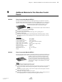
Additional Modules for Fire Detection Control Panels
223024
223026
222007
222004
222010
229008
7
Serial Interface Module SIM216-1 . . . . . . . . . . . . . . . . . . . . . . . . . . . . . . . . . . . . . . . . . . . . . . . . . . . . . . . . . . . . . . . . . .
Interface Adapter Module IAM216-1E . . . . . . . . . . . . . . . . . . . . . . . . . . . . . . . . . . . . . . . . . . . . . . . . . . . . . . . . . . . . .
Ethernet Module ENM2-1 . . . . . . . . . . . . . . . . . . . . . . . . . . . . . . . . . . . . . . . . . . . . . . . . . . . . . . . . . . . . . . . . . . . . . . . . .
Remote Access Module PSTN FZP2-1 . . . . . . . . . . . . . . . . . . . . . . . . . . . . . . . . . . . . . . . . . . . . . . . . . . . . . . . . . . . . .
Remote Access Module GSM/GPRS FZG2-1 . . . . . . . . . . . . . . . . . . . . . . . . . . . . . . . . . . . . . . . . . . . . . . . . . . . . . . .
SMS/E-Mail Transmitter Module SMS2-1/D1 . . . . . . . . . . . . . . . . . . . . . . . . . . . . . . . . . . . . . . . . . . . . . . . . . . . . . .
Gateway/IEC870-5-101/-104/BC216 IEC870-BC216-GW . . . . . . . . . . . . . . . . . . . . . . . . . . . . . . . . . . . . . . . . .
Long Distance Modem BCnet216 MOD-1 . . . . . . . . . . . . . . . . . . . . . . . . . . . . . . . . . . . . . . . . . . . . . . . . . . . . . . . . .
Multimode Fibre Gateway BCnet216 LWL-MM-2 . . . . . . . . . . . . . . . . . . . . . . . . . . . . . . . . . . . . . . . . . . . . . . . . . .
Singlemode Fibre Gateway BCnet216 LWL-SM-2 . . . . . . . . . . . . . . . . . . . . . . . . . . . . . . . . . . . . . . . . . . . . . . . . . .
ZLT Interface License ZLT-SS . . . . . . . . . . . . . . . . . . . . . . . . . . . . . . . . . . . . . . . . . . . . . . . . . . . . . . . . . . . . . . . . . . . . .
ESPA 4.4.4 Interface License ESPA-SS . . . . . . . . . . . . . . . . . . . . . . . . . . . . . . . . . . . . . . . . . . . . . . . . . . . . . . . . . . . .
BCnet-LBC Gateway/N.OP./6HU BCNET-LBC-GW . . . . . . . . . . . . . . . . . . . . . . . . . . . . . . . . . . . . . . . . . . . . . .
LBC Sub-Unit License LBC-UZ . . . . . . . . . . . . . . . . . . . . . . . . . . . . . . . . . . . . . . . . . . . . . . . . . . . . . . . . . . . . . . . . . . .
Programming Cable BC216/RS232 PK216-1 . . . . . . . . . . . . . . . . . . . . . . . . . . . . . . . . . . . . . . . . . . . . . . . . . . . . . .
Remote Display and Operating Panel ABF216-1/INT1 . . . . . . . . . . . . . . . . . . . . . . . . . . . . . . . . . . . . . . . . . . . . . .
Remote Display and Operating Panel ABF216-1/A1 . . . . . . . . . . . . . . . . . . . . . . . . . . . . . . . . . . . . . . . . . . . . . . . .
Remote Display and Operating Panel ABF216-1/D1 . . . . . . . . . . . . . . . . . . . . . . . . . . . . . . . . . . . . . . . . . . . . . . . .
Remote Display and Operating Panel ABF216-1/B1 . . . . . . . . . . . . . . . . . . . . . . . . . . . . . . . . . . . . . . . . . . . . . . . .
Remote Display and Operating Panel ABF216-1/CZ1 . . . . . . . . . . . . . . . . . . . . . . . . . . . . . . . . . . . . . . . . . . . . . . .
Remote Display and Operating Panel ABF216-1/H1 . . . . . . . . . . . . . . . . . . . . . . . . . . . . . . . . . . . . . . . . . . . . . . . .
Remote Display and Operating Panel ABF216-1/NL1 . . . . . . . . . . . . . . . . . . . . . . . . . . . . . . . . . . . . . . . . . . . . . . .
Remote Display and Operating Panel ABF216-1/SK1 . . . . . . . . . . . . . . . . . . . . . . . . . . . . . . . . . . . . . . . . . . . . . . .
Remote Display and Operating Panel ABF216-1/RUS1 . . . . . . . . . . . . . . . . . . . . . . . . . . . . . . . . . . . . . . . . . . . . .
Remote Display and Operating Panel ABF216-1/SLO1 . . . . . . . . . . . . . . . . . . . . . . . . . . . . . . . . . . . . . . . . . . . . .
Remote Display and Operating Panel ABF216-1/I1 . . . . . . . . . . . . . . . . . . . . . . . . . . . . . . . . . . . . . . . . . . . . . . . . .
Remote Display and Operating Panel ABF216-1/PL1 . . . . . . . . . . . . . . . . . . . . . . . . . . . . . . . . . . . . . . . . . . . . . . .
Remote Display and Operating Panel ABF216-1/HR1 . . . . . . . . . . . . . . . . . . . . . . . . . . . . . . . . . . . . . . . . . . . . . .
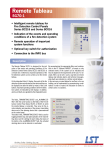
Remote Tableau SG58-2/A1 . . . . . . . . . . . . . . . . . . . . . . . . . . . . . . . . . . . . . . . . . . . . . . . . . . . . . . . . . . . . . . . . . . . . . . .
Remote Tableau SG58-2/NL1 . . . . . . . . . . . . . . . . . . . . . . . . . . . . . . . . . . . . . . . . . . . . . . . . . . . . . . . . . . . . . . . . . . . . . .
Remote Tableau SG58-2/B1 . . . . . . . . . . . . . . . . . . . . . . . . . . . . . . . . . . . . . . . . . . . . . . . . . . . . . . . . . . . . . . . . . . . . . . .
Remote Tableau SG58-2/CZ1 . . . . . . . . . . . . . . . . . . . . . . . . . . . . . . . . . . . . . . . . . . . . . . . . . . . . . . . . . . . . . . . . . . . . . .
Remote Display Panel SG48-2 . . . . . . . . . . . . . . . . . . . . . . . . . . . . . . . . . . . . . . . . . . . . . . . . . . . . . . . . . . . . . . . . . . . . .
Remote Indicator PA58-1 . . . . . . . . . . . . . . . . . . . . . . . . . . . . . . . . . . . . . . . . . . . . . . . . . . . . . . . . . . . . . . . . . . . . . . . . . .
LED Display Tableau LAT288-1 . . . . . . . . . . . . . . . . . . . . . . . . . . . . . . . . . . . . . . . . . . . . . . . . . . . . . . . . . . . . . . . . . . .
LED Display Tableau LAT288-1CE . . . . . . . . . . . . . . . . . . . . . . . . . . . . . . . . . . . . . . . . . . . . . . . . . . . . . . . . . . . . . . .
Remote Tableau Drive Unit PTU288-1 . . . . . . . . . . . . . . . . . . . . . . . . . . . . . . . . . . . . . . . . . . . . . . . . . . . . . . . . . . . . .
LED Connection Module LAM48-1 . . . . . . . . . . . . . . . . . . . . . . . . . . . . . . . . . . . . . . . . . . . . . . . . . . . . . . . . . . . . . . . .
LED Assembled Green/10pcs. LED-GN/10 . . . . . . . . . . . . . . . . . . . . . . . . . . . . . . . . . . . . . . . . . . . . . . . . . . . . . . . .
LED Assembled Red/10pcs. LED-RT/10 . . . . . . . . . . . . . . . . . . . . . . . . . . . . . . . . . . . . . . . . . . . . . . . . . . . . . . . . . . .
LED Assembled Yellow/10pcs. LED-GE/10 . . . . . . . . . . . . . . . . . . . . . . . . . . . . . . . . . . . . . . . . . . . . . . . . . . . . . . . .
B
68
68
68
69
69
69
69
69
69
69
69
69
70
70
70
70
71
71
71
72
72
73
74
74
75
75
VIII
259013
9
Conventional Detectors Series FC600
241070
242070
242071
10
Optical Smoke Detector/Conv./300/SS 2351E . . . . . . . . . . . . . . . . . . . . . . . . . . . . . . . . . . . . . . . . . . . . . . . . . . . . . .
Optical-Thermal Detector/Conv./300/SS 2351TEM . . . . . . . . . . . . . . . . . . . . . . . . . . . . . . . . . . . . . . . . . . . . . . . .
Thermal ROR Detector/Conv./300/SS 5351E . . . . . . . . . . . . . . . . . . . . . . . . . . . . . . . . . . . . . . . . . . . . . . . . . . . . . .
Thermal Max Detector/Conv./300/SS 5351TE . . . . . . . . . . . . . . . . . . . . . . . . . . . . . . . . . . . . . . . . . . . . . . . . . . . . .
Thermal Max Detector/Conv./300/SS 4351E . . . . . . . . . . . . . . . . . . . . . . . . . . . . . . . . . . . . . . . . . . . . . . . . . . . . . . .
Optical Smoke Detector/Conv./1000/SS ECO1003 . . . . . . . . . . . . . . . . . . . . . . . . . . . . . . . . . . . . . . . . . . . . . . . . .
Optical-Thermal Detector/Conv./1000/SS ECO1002 . . . . . . . . . . . . . . . . . . . . . . . . . . . . . . . . . . . . . . . . . . . . . . .
Thermal Max Detector/Conv./1000/SS ECO1004T . . . . . . . . . . . . . . . . . . . . . . . . . . . . . . . . . . . . . . . . . . . . . . . . .
Thermal ROR Detector/Conv./1000/SS ECO1005 . . . . . . . . . . . . . . . . . . . . . . . . . . . . . . . . . . . . . . . . . . . . . . . . .
Thermal Max Detector/Conv./1000/SS ECO1005T . . . . . . . . . . . . . . . . . . . . . . . . . . . . . . . . . . . . . . . . . . . . . . . . .
81
82
83
84
84
85
86
87
87
88
Analogue Detectors and Modules Series 200/500
240013
241010
241050
241020
241051
242002
241019
249046
249100
249101
249102
249115
249103
249105
249106
249116
249045
249104
249092
249095
249090
249091
249003
13
Detector Base/FC600 FC600/BR . . . . . . . . . . . . . . . . . . . . . . . . . . . . . . . . . . . . . . . . . . . . . . . . . . . . . . . . . . . . . . . . . . . 79
Detector Base with Diode/FC600 FC600/BRD . . . . . . . . . . . . . . . . . . . . . . . . . . . . . . . . . . . . . . . . . . . . . . . . . . . . . 79
Detector Relay Base/FC600 FC600/BREL . . . . . . . . . . . . . . . . . . . . . . . . . . . . . . . . . . . . . . . . . . . . . . . . . . . . . . . . . 80
Conventional Detectors Series 300/ECO1000
241040
241041
242040
242042
242041
241045
241046
242047
242045
242046
12
Optical Smoke Detector/Conv./FC600 FC600/O . . . . . . . . . . . . . . . . . . . . . . . . . . . . . . . . . . . . . . . . . . . . . . . . . . . . 76
Thermal ROR Detector/Conv./FC600 FC600/TDIFF/57 . . . . . . . . . . . . . . . . . . . . . . . . . . . . . . . . . . . . . . . . . . . . 77
Thermal Max Detector/Conv./FC600 FC600/TMAX/78 . . . . . . . . . . . . . . . . . . . . . . . . . . . . . . . . . . . . . . . . . . . . 77
Acessories for Series FC600
246070
246071
246072
11
Cord 2 Wire for LED Connection/10pcs. LED-LEITUNG/10 . . . . . . . . . . . . . . . . . . . . . . . . . . . . . . . . . . . . . . . 75
Ionisation Smoke Detector/Anal./200/SS 1251E . . . . . . . . . . . . . . . . . . . . . . . . . . . . . . . . . . . . . . . . . . . . . . . . . . . . 90
Optical Smoke Detector/Anal./200/SS ND2251EM . . . . . . . . . . . . . . . . . . . . . . . . . . . . . . . . . . . . . . . . . . . . . . . . . 90
Optical Laser Detector/Anal./200/SS 7251 . . . . . . . . . . . . . . . . . . . . . . . . . . . . . . . . . . . . . . . . . . . . . . . . . . . . . . . . . . 91
Optical-Thermal Detector/Anal./200/SS 2251TEM . . . . . . . . . . . . . . . . . . . . . . . . . . . . . . . . . . . . . . . . . . . . . . . . . 92
Optical-Thermal-CO-IR Detector/Anal./200/SS 2251CTLE . . . . . . . . . . . . . . . . . . . . . . . . . . . . . . . . . . . . . . . . . 93
Thermal Detector/Anal./200/SS 5251EM . . . . . . . . . . . . . . . . . . . . . . . . . . . . . . . . . . . . . . . . . . . . . . . . . . . . . . . . . . . 94
Optical Filtrex Smoke Detector/Anal./500/SS FTX-P1 . . . . . . . . . . . . . . . . . . . . . . . . . . . . . . . . . . . . . . . . . . . . . . 94
Monitor Module/Anal./500/SS M503ME . . . . . . . . . . . . . . . . . . . . . . . . . . . . . . . . . . . . . . . . . . . . . . . . . . . . . . . . . . . 95
Monitor Module 1xSurv.In/Anal./200/SS M210E . . . . . . . . . . . . . . . . . . . . . . . . . . . . . . . . . . . . . . . . . . . . . . . . . . . 96
Monitor Module 2xSurv.In/Anal./200/SS M220E . . . . . . . . . . . . . . . . . . . . . . . . . . . . . . . . . . . . . . . . . . . . . . . . . . . 96
Module 2xSurv.In 1xRel.Out/Anal./200/SS M221E . . . . . . . . . . . . . . . . . . . . . . . . . . . . . . . . . . . . . . . . . . . . . . . . 97
Monitor Module 10xSurv.In/Anal./200/SS IM-10 . . . . . . . . . . . . . . . . . . . . . . . . . . . . . . . . . . . . . . . . . . . . . . . . . . . 97
Control Module 1xSurv.Out/Anal./200/SS M201E . . . . . . . . . . . . . . . . . . . . . . . . . . . . . . . . . . . . . . . . . . . . . . . . . 98
Control Module 1xRel.Out/Anal./200/SS M201E-240 . . . . . . . . . . . . . . . . . . . . . . . . . . . . . . . . . . . . . . . . . . . . . . 98
Control Module 1xRel.Out-DIN/Anal./200/SS M201E-240-DIN . . . . . . . . . . . . . . . . . . . . . . . . . . . . . . . . . . . . 99
Control Module 6xRel.Out/Anal./200/SS CR-6 . . . . . . . . . . . . . . . . . . . . . . . . . . . . . . . . . . . . . . . . . . . . . . . . . . . . . 99
Conventional Zone Module/Anal./500/SS M512ME . . . . . . . . . . . . . . . . . . . . . . . . . . . . . . . . . . . . . . . . . . . . . . . 100
Conventional Zone Module/Anal./200/SS M210E-CZ . . . . . . . . . . . . . . . . . . . . . . . . . . . . . . . . . . . . . . . . . . . . . 100
Multi Module/Mounting Rail MEA244-1/TR . . . . . . . . . . . . . . . . . . . . . . . . . . . . . . . . . . . . . . . . . . . . . . . . . . . . . . 101
Multi Module/Panel-Mounting MEA244-1/E . . . . . . . . . . . . . . . . . . . . . . . . . . . . . . . . . . . . . . . . . . . . . . . . . . . . . . 102
Limit Switch/Anal./500/SS EDS500-1 . . . . . . . . . . . . . . . . . . . . . . . . . . . . . . . . . . . . . . . . . . . . . . . . . . . . . . . . . . . . . 103
Monitor Module/Box/Anal./500/SS ÜMB500-1 . . . . . . . . . . . . . . . . . . . . . . . . . . . . . . . . . . . . . . . . . . . . . . . . . . . 103
Isolator Module/Anal./500/200/SS ISM1-2 . . . . . . . . . . . . . . . . . . . . . . . . . . . . . . . . . . . . . . . . . . . . . . . . . . . . . . . . 103
Acessories for Series 300/ECO1000/200/500
246008
246100
246101
246102
246140
246141
246142
246143
Detector Base/Conv./400/100/300/SS B401RM . . . . . . . . . . . . . . . . . . . . . . . . . . . . . . . . . . . . . . . . . . . . . . . . . . .
Detector Relay Base/Conv./300/SS B324RL . . . . . . . . . . . . . . . . . . . . . . . . . . . . . . . . . . . . . . . . . . . . . . . . . . . . . .
Detector Relay Base/Conv./300/SS B312RL . . . . . . . . . . . . . . . . . . . . . . . . . . . . . . . . . . . . . . . . . . . . . . . . . . . . . .
Detector Relay Base/Conv./300/SS B312NL . . . . . . . . . . . . . . . . . . . . . . . . . . . . . . . . . . . . . . . . . . . . . . . . . . . . . .
Detector Base/Conv./1000/SS ECO1000BR1000 . . . . . . . . . . . . . . . . . . . . . . . . . . . . . . . . . . . . . . . . . . . . . . . . .
Detector Relay Base/Conv./1000/SS ECO1000BREL24L . . . . . . . . . . . . . . . . . . . . . . . . . . . . . . . . . . . . . . . . .
Detector Relay Base/Conv./SS ECO1000BREL12L . . . . . . . . . . . . . . . . . . . . . . . . . . . . . . . . . . . . . . . . . . . . . . .
Detector Relay Base/Conv./SS ECO1000BREL12NL . . . . . . . . . . . . . . . . . . . . . . . . . . . . . . . . . . . . . . . . . . . . .
B
105
105
106
106
107
107
108
108
169 / BB072001.SAM
/0720-01/0100
IX
246002
246015
246016
246013
246018
246012
246113
246111
246112
246150
249212
249214
246006
246009
246010
249012
246017
249109
249110
249108
249111
249117
249004
249014
249027
249020
249044
249635
249640
244009
241038
244008
244005
244010
244011
244012
249047
14
Ionisation Smoke Detector/Conv./65/Apo GI-55000-217 . . . . . . . . . . . . . . . . . . . . . . . . . . . . . . . . . . . . . . . . . . .
Optical Smoke Detector/Conv./65/Apo GO-55000-317 . . . . . . . . . . . . . . . . . . . . . . . . . . . . . . . . . . . . . . . . . . . .
Thermal ROR Detector/Conv./65/Apo GD-55000-122 . . . . . . . . . . . . . . . . . . . . . . . . . . . . . . . . . . . . . . . . . . . .
Thermal ROR Detector/Conv./65/Apo GD-55000-127 . . . . . . . . . . . . . . . . . . . . . . . . . . . . . . . . . . . . . . . . . . . .
Thermal ROR Detector/Conv./65/Apo GD-55000-132 . . . . . . . . . . . . . . . . . . . . . . . . . . . . . . . . . . . . . . . . . . . .
Thermal Max Detector/Conv./65/Apo GM-55000-137 . . . . . . . . . . . . . . . . . . . . . . . . . . . . . . . . . . . . . . . . . . . . .
Optical Smoke Detector/Conv./ORBIS/Apo OP-12001 . . . . . . . . . . . . . . . . . . . . . . . . . . . . . . . . . . . . . . . . . . . .
Optical-Thermal Detector/Conv./ORBIS/Apo OH-13001 . . . . . . . . . . . . . . . . . . . . . . . . . . . . . . . . . . . . . . . . . .
Thermal ROR Detector/Conv./ORBIS/Apo HT-11001 . . . . . . . . . . . . . . . . . . . . . . . . . . . . . . . . . . . . . . . . . . . . .
Thermal Max Detector/Conv./ORBIS/Apo HT-11002 . . . . . . . . . . . . . . . . . . . . . . . . . . . . . . . . . . . . . . . . . . . . .
Thermal ROR Detector/Conv./ORBIS/Apo HT-11003 . . . . . . . . . . . . . . . . . . . . . . . . . . . . . . . . . . . . . . . . . . . . .
Thermal Max Detector/Conv./ORBIS/Apo HT-11004 . . . . . . . . . . . . . . . . . . . . . . . . . . . . . . . . . . . . . . . . . . . . .
Thermal ROR Detector/Conv./ORBIS/Apo HT-11005 . . . . . . . . . . . . . . . . . . . . . . . . . . . . . . . . . . . . . . . . . . . . .
Thermal Max Detector/Conv./ORBIS/Apo HT-11006 . . . . . . . . . . . . . . . . . . . . . . . . . . . . . . . . . . . . . . . . . . . . .
126
126
127
127
128
129
129
130
131
132
132
133
134
134
Analogue Detectors and Modules Series XP95/DISCOVERY
240024
241023
242023
241030
240026
241027
169 / BB072001.SAM
/0720-01/0100
109
109
110
110
111
111
112
112
113
113
114
114
114
115
115
116
116
116
117
117
117
118
118
119
119
119
120
121
121
122
122
123
123
124
124
124
124
Conventional Detectors Series 65/ORBIS
240027
241026
242024
242025
242026
242027
241060
241061
242030
242031
242032
242033
242034
242035
15
Detector Base/Anal./500/200/SS B501 . . . . . . . . . . . . . . . . . . . . . . . . . . . . . . . . . . . . . . . . . . . . . . . . . . . . . . . . . . . .
Detector Base/Anal./500/200/SS B501DG . . . . . . . . . . . . . . . . . . . . . . . . . . . . . . . . . . . . . . . . . . . . . . . . . . . . . . . .
Detector Relay Base/Anal./500/200/SS B524RTE . . . . . . . . . . . . . . . . . . . . . . . . . . . . . . . . . . . . . . . . . . . . . . . . .
Isolator Detector Base/Anal./500/200/SS B524IEFT-1 . . . . . . . . . . . . . . . . . . . . . . . . . . . . . . . . . . . . . . . . . . . . .
Detector Heater Base/Anal./500/SS B524HTR . . . . . . . . . . . . . . . . . . . . . . . . . . . . . . . . . . . . . . . . . . . . . . . . . . . .
Detector Base Filtrex/Anal./500/SS B524FTXE . . . . . . . . . . . . . . . . . . . . . . . . . . . . . . . . . . . . . . . . . . . . . . . . . . .
Zonal Display Unit/Conv./300/SS S300ZDU . . . . . . . . . . . . . . . . . . . . . . . . . . . . . . . . . . . . . . . . . . . . . . . . . . . . . .
Remote Program and Test Unit/Conv./300/SS S300RPTU . . . . . . . . . . . . . . . . . . . . . . . . . . . . . . . . . . . . . . . . .
Satellite Unit for Remote Programming/Conv./300/SS S300SAT . . . . . . . . . . . . . . . . . . . . . . . . . . . . . . . . . . .
Remote Test Unit/Conv./300/1000/SS ECO1000RTU . . . . . . . . . . . . . . . . . . . . . . . . . . . . . . . . . . . . . . . . . . . . .
Battery for ECO1000RTU 6V-V11GA . . . . . . . . . . . . . . . . . . . . . . . . . . . . . . . . . . . . . . . . . . . . . . . . . . . . . . . . . . . .
Battery for ECO1000RTU 6V-476A . . . . . . . . . . . . . . . . . . . . . . . . . . . . . . . . . . . . . . . . . . . . . . . . . . . . . . . . . . . . . .
Base Adapter/SS MZP500-1 . . . . . . . . . . . . . . . . . . . . . . . . . . . . . . . . . . . . . . . . . . . . . . . . . . . . . . . . . . . . . . . . . . . . . .
Surface Mounting Kit/SS SMK400 . . . . . . . . . . . . . . . . . . . . . . . . . . . . . . . . . . . . . . . . . . . . . . . . . . . . . . . . . . . . . . . .
Recessed Mounting Kit/SS RMK400 . . . . . . . . . . . . . . . . . . . . . . . . . . . . . . . . . . . . . . . . . . . . . . . . . . . . . . . . . . . . . .
Wet Base Shroud/SS WB1 . . . . . . . . . . . . . . . . . . . . . . . . . . . . . . . . . . . . . . . . . . . . . . . . . . . . . . . . . . . . . . . . . . . . . . . .
Cover Plate for Base Bx01/Bx24 BC-Bx01 . . . . . . . . . . . . . . . . . . . . . . . . . . . . . . . . . . . . . . . . . . . . . . . . . . . . . . . .
Base for Mounting Plate for M200/SS M200E-PMB . . . . . . . . . . . . . . . . . . . . . . . . . . . . . . . . . . . . . . . . . . . . . .
Base for Carrier Rail for M200/SS M200E-DIN . . . . . . . . . . . . . . . . . . . . . . . . . . . . . . . . . . . . . . . . . . . . . . . . . . .
Surface Mounting Box for M200/SS M200SMB . . . . . . . . . . . . . . . . . . . . . . . . . . . . . . . . . . . . . . . . . . . . . . . . . .
Surface Mounting Box for MS200/SS M200SMB-KO . . . . . . . . . . . . . . . . . . . . . . . . . . . . . . . . . . . . . . . . . . . . .
Surface Mounting Box for Multimodule/SS M200-SMB-MM . . . . . . . . . . . . . . . . . . . . . . . . . . . . . . . . . . . . . .
Surface Mounting Box for M500/SS SMB500 . . . . . . . . . . . . . . . . . . . . . . . . . . . . . . . . . . . . . . . . . . . . . . . . . . . .
Power Supply Unit for Detector Heater MH-TR1 . . . . . . . . . . . . . . . . . . . . . . . . . . . . . . . . . . . . . . . . . . . . . . . . . .
Detector Heater/Anal./500/200/SS MH500-1 . . . . . . . . . . . . . . . . . . . . . . . . . . . . . . . . . . . . . . . . . . . . . . . . . . . . . .
Address Module/Conv. NG58-1 . . . . . . . . . . . . . . . . . . . . . . . . . . . . . . . . . . . . . . . . . . . . . . . . . . . . . . . . . . . . . . . . . . .
Detector Mounting Bracket MMW1-1 . . . . . . . . . . . . . . . . . . . . . . . . . . . . . . . . . . . . . . . . . . . . . . . . . . . . . . . . . . . . .
Trapezoid Steel Bracket TBH800-1 . . . . . . . . . . . . . . . . . . . . . . . . . . . . . . . . . . . . . . . . . . . . . . . . . . . . . . . . . . . . . . .
Protective Cage BWS-1/D1 . . . . . . . . . . . . . . . . . . . . . . . . . . . . . . . . . . . . . . . . . . . . . . . . . . . . . . . . . . . . . . . . . . . . . . .
Duct Detector/400/OM DH400P . . . . . . . . . . . . . . . . . . . . . . . . . . . . . . . . . . . . . . . . . . . . . . . . . . . . . . . . . . . . . . . . . .
Optical Smoke Detector/Conv./100/SS 2151E-LC . . . . . . . . . . . . . . . . . . . . . . . . . . . . . . . . . . . . . . . . . . . . . . . . .
Duct Detector Housing/Anal./500/200/SS DH500 . . . . . . . . . . . . . . . . . . . . . . . . . . . . . . . . . . . . . . . . . . . . . . . . .
Duct Detector Pipe/0.3-0.6M/SS ST-1.5 . . . . . . . . . . . . . . . . . . . . . . . . . . . . . . . . . . . . . . . . . . . . . . . . . . . . . . . . . . .
Duct Detector Pipe/0.6-1.2M/SS ST-3 . . . . . . . . . . . . . . . . . . . . . . . . . . . . . . . . . . . . . . . . . . . . . . . . . . . . . . . . . . . . .
Duct Detector Pipe/1.2-2.4M/SS ST-5 . . . . . . . . . . . . . . . . . . . . . . . . . . . . . . . . . . . . . . . . . . . . . . . . . . . . . . . . . . . . .
Duct Detector Pipe/2.4-3.7M/SS ST-10 . . . . . . . . . . . . . . . . . . . . . . . . . . . . . . . . . . . . . . . . . . . . . . . . . . . . . . . . . . .
Replacement Filter for Filtrex RF-FTX . . . . . . . . . . . . . . . . . . . . . . . . . . . . . . . . . . . . . . . . . . . . . . . . . . . . . . . . . . . . .
Ionisation Smoke Detector/Anal./XP95/Apo AI-55000-520 . . . . . . . . . . . . . . . . . . . . . . . . . . . . . . . . . . . . . . . .
Optical Smoke Detector/Anal./XP95/Apo AO-55000-620 . . . . . . . . . . . . . . . . . . . . . . . . . . . . . . . . . . . . . . . . . .
Thermal Detector/Anal./XP95/Apo AW-55000-420 . . . . . . . . . . . . . . . . . . . . . . . . . . . . . . . . . . . . . . . . . . . . . . .
Optical-Thermal Detector/Anal./XP95/Apo AMS-55000-885 . . . . . . . . . . . . . . . . . . . . . . . . . . . . . . . . . . . . . .
Ionisation Smoke Detector/Anal./Disc/Apo AI-58000-500 . . . . . . . . . . . . . . . . . . . . . . . . . . . . . . . . . . . . . . . . . .
Optical Smoke Detector/Anal./Disc/Apo AO-58000-600 . . . . . . . . . . . . . . . . . . . . . . . . . . . . . . . . . . . . . . . . . . .
B
136
136
137
138
138
139
X
242028
241022
243100
249061
249060
249072
249076
249077
249078
249073
249074
249075
249029
249070
16
140
141
141
142
142
143
143
144
145
145
146
146
147
148
Acessories for Series 65/ORBIS/XP95/DISCOVERY
246021
246035
246042
246041
246025
246036
246037
246034
246029
246030
246031
246032
246033
249028
249039
17
Thermal Detector/Anal./Disc/Apo AD-58000-400 . . . . . . . . . . . . . . . . . . . . . . . . . . . . . . . . . . . . . . . . . . . . . . . . .
Optical-Thermal Detector/Anal./Disc/Apo AMS-58000-700 . . . . . . . . . . . . . . . . . . . . . . . . . . . . . . . . . . . . . . . .
CO-Detector/Anal./Disc/Apo AC-58000-300 . . . . . . . . . . . . . . . . . . . . . . . . . . . . . . . . . . . . . . . . . . . . . . . . . . . . . .
Monitor Module/Anal./XP95/Apo ÜMM-55000-833 . . . . . . . . . . . . . . . . . . . . . . . . . . . . . . . . . . . . . . . . . . . . . .
Monitor Module-Interrupt/Anal./XP95/Apo ÜMI-55000-832 . . . . . . . . . . . . . . . . . . . . . . . . . . . . . . . . . . . . . .
Monitor Module/Anal./XP95/Apo ÜMS-55000-841 . . . . . . . . . . . . . . . . . . . . . . . . . . . . . . . . . . . . . . . . . . . . . . .
Module 1xSurv.In 1xRel.Out/Apo 55000-847 . . . . . . . . . . . . . . . . . . . . . . . . . . . . . . . . . . . . . . . . . . . . . . . . . . . . .
Module 3xSurv.In 3xRel.Out/Apo 55000-588 . . . . . . . . . . . . . . . . . . . . . . . . . . . . . . . . . . . . . . . . . . . . . . . . . . . . .
Module 1xSurv.In 1xRel.Out-230/Apo 55000-875 . . . . . . . . . . . . . . . . . . . . . . . . . . . . . . . . . . . . . . . . . . . . . . . .
Control Module/Anal./XP95/Apo SMÜ-55000-852 . . . . . . . . . . . . . . . . . . . . . . . . . . . . . . . . . . . . . . . . . . . . . . . .
Control Module/Anal./XP95/Apo SMK-55000-849 . . . . . . . . . . . . . . . . . . . . . . . . . . . . . . . . . . . . . . . . . . . . . . . .
Conventional Zone Module/Anal./XP95/Apo GWM-55000-845 . . . . . . . . . . . . . . . . . . . . . . . . . . . . . . . . . . .
Isolator Module/Anal./Apo ISM1-3 . . . . . . . . . . . . . . . . . . . . . . . . . . . . . . . . . . . . . . . . . . . . . . . . . . . . . . . . . . . . . . . .
Isolator Module/Board/Apo 43781-552 . . . . . . . . . . . . . . . . . . . . . . . . . . . . . . . . . . . . . . . . . . . . . . . . . . . . . . . . . . . .
Detector Base/Conv./60/65/Apo GSA-45681-200 . . . . . . . . . . . . . . . . . . . . . . . . . . . . . . . . . . . . . . . . . . . . . . . . .
Detector Base/Conv./60/65/Apo 45681-251 . . . . . . . . . . . . . . . . . . . . . . . . . . . . . . . . . . . . . . . . . . . . . . . . . . . . . . .
Detector Base/Conv./ORBIS/Apo MB-00001 . . . . . . . . . . . . . . . . . . . . . . . . . . . . . . . . . . . . . . . . . . . . . . . . . . . . .
Detector Relay Base/Conv./ORBIS/Apo RB-10004 . . . . . . . . . . . . . . . . . . . . . . . . . . . . . . . . . . . . . . . . . . . . . . . .
Detector Base/Anal./Apo ASA-45681-210 . . . . . . . . . . . . . . . . . . . . . . . . . . . . . . . . . . . . . . . . . . . . . . . . . . . . . . . . .
Isolator Detector Base/Anal./Apo AISA-45681-321 . . . . . . . . . . . . . . . . . . . . . . . . . . . . . . . . . . . . . . . . . . . . . . . .
Detector Relay Base/Anal./XP95/DISC/Apo ASR-45681-242 . . . . . . . . . . . . . . . . . . . . . . . . . . . . . . . . . . . . . .
Detector Base/Anal./Apo 45681-250 . . . . . . . . . . . . . . . . . . . . . . . . . . . . . . . . . . . . . . . . . . . . . . . . . . . . . . . . . . . . . .
Conduit Box/Apo SZA-45681-204 . . . . . . . . . . . . . . . . . . . . . . . . . . . . . . . . . . . . . . . . . . . . . . . . . . . . . . . . . . . . . . . .
Backplate/Apo SZPL-45681-233 . . . . . . . . . . . . . . . . . . . . . . . . . . . . . . . . . . . . . . . . . . . . . . . . . . . . . . . . . . . . . . . . . .
Duct Detector Housing/Anal./Apo LG-53546-016 . . . . . . . . . . . . . . . . . . . . . . . . . . . . . . . . . . . . . . . . . . . . . . . . .
Detector Heater/Conv./60/65/Apo MH60-1 . . . . . . . . . . . . . . . . . . . . . . . . . . . . . . . . . . . . . . . . . . . . . . . . . . . . . . . .
Detector Heater/Anal./Apo MH95-1 . . . . . . . . . . . . . . . . . . . . . . . . . . . . . . . . . . . . . . . . . . . . . . . . . . . . . . . . . . . . . . .
Address Module/Conv./Apo NG60-1 . . . . . . . . . . . . . . . . . . . . . . . . . . . . . . . . . . . . . . . . . . . . . . . . . . . . . . . . . . . . . .
Address Cards/100pcs./Anal./XP95/Disc/Apo CK-38531-771 . . . . . . . . . . . . . . . . . . . . . . . . . . . . . . . . . . . . . .
149
149
150
150
151
151
152
153
153
153
154
154
155
155
156
Manual Call Points
245302
245356
245352
245417
245355
245362
245372
245415
245392
245389
245402
245395
245429
245396
249096
249633
249634
249636
249631
219006
2171612
2171620
2171621
2171619
249024
245040
245041
245042
Manual Call Point/EN 54/Red/Conv. HFM/3/11/02 . . . . . . . . . . . . . . . . . . . . . . . . . . . . . . . . . . . . . . . . . . . . . . .
Manual Call Point/Red/Conv. HM/3/11/01/02 . . . . . . . . . . . . . . . . . . . . . . . . . . . . . . . . . . . . . . . . . . . . . . . . . . . . .
Manual Call Point/Blue/Conv. HM/5/11/02/02 . . . . . . . . . . . . . . . . . . . . . . . . . . . . . . . . . . . . . . . . . . . . . . . . . . . .
Manual Call Point/Blue/Conv. HM/5/11/18/02 . . . . . . . . . . . . . . . . . . . . . . . . . . . . . . . . . . . . . . . . . . . . . . . . . . . .
Manual Call Point/Yellow/Conv. HM/1/11/05/02 . . . . . . . . . . . . . . . . . . . . . . . . . . . . . . . . . . . . . . . . . . . . . . . . . .
Manual Call Point/Red/Anal./SS HFM/3/22/02 . . . . . . . . . . . . . . . . . . . . . . . . . . . . . . . . . . . . . . . . . . . . . . . . . . . .
Manual Call Point/Blue/Anal./SS HM/5/22/02/02 . . . . . . . . . . . . . . . . . . . . . . . . . . . . . . . . . . . . . . . . . . . . . . . . .
Manual Call Point/Blue/Anal./SS HM/5/22/18/02 . . . . . . . . . . . . . . . . . . . . . . . . . . . . . . . . . . . . . . . . . . . . . . . . .
Manual Call Point/Yellow/Anal./SS HM/1/22/05/02 . . . . . . . . . . . . . . . . . . . . . . . . . . . . . . . . . . . . . . . . . . . . . . .
Manual Call Point/Grey/Anal./SS HM/7/22/03/02 . . . . . . . . . . . . . . . . . . . . . . . . . . . . . . . . . . . . . . . . . . . . . . . . .
Manual Call Point/EN 54/Red/Anal./Apo HFM/3/32/02 . . . . . . . . . . . . . . . . . . . . . . . . . . . . . . . . . . . . . . . . . . .
Manual Call Point/Blue/Anal./Apo HM/5/32/02/02 . . . . . . . . . . . . . . . . . . . . . . . . . . . . . . . . . . . . . . . . . . . . . . . .
Manual Call Point/Blue/Anal./Apo HM/5/32/18/02 . . . . . . . . . . . . . . . . . . . . . . . . . . . . . . . . . . . . . . . . . . . . . . . .
Manual Call Point/Yellow/Anal./Apo HM/1/32/05/02 . . . . . . . . . . . . . . . . . . . . . . . . . . . . . . . . . . . . . . . . . . . . .
MCP Coding Module MCM1-1 . . . . . . . . . . . . . . . . . . . . . . . . . . . . . . . . . . . . . . . . . . . . . . . . . . . . . . . . . . . . . . . . . . .
Protective Cover V2A for Manual Call Point/Red WG/ROT-E-1 . . . . . . . . . . . . . . . . . . . . . . . . . . . . . . . . . . .
Protective Cover V2A for Manual Call Point/Blue WG/BLAU-E-1 . . . . . . . . . . . . . . . . . . . . . . . . . . . . . . . . .
Protective Cover V2A for Manual Call Point/Yellow WG/GELB-E-1 . . . . . . . . . . . . . . . . . . . . . . . . . . . . . .
Protection Kit IP54 for Manual Call Point HFM/HM-ZS-IP54 . . . . . . . . . . . . . . . . . . . . . . . . . . . . . . . . . . . . . .
Key for Manual Call Point SCH-HFM/HM . . . . . . . . . . . . . . . . . . . . . . . . . . . . . . . . . . . . . . . . . . . . . . . . . . . . . . . .
Replacement Glass for Manual Call Point ET-SCH-HFM . . . . . . . . . . . . . . . . . . . . . . . . . . . . . . . . . . . . . . . . . .
Replacement Glass for Manual Call Point/Red ET-SCH-HM-RT . . . . . . . . . . . . . . . . . . . . . . . . . . . . . . . . . . .
Replacement Glass for Manual Call Point/Blue ET-SCH-HM-BL . . . . . . . . . . . . . . . . . . . . . . . . . . . . . . . . . .
Replacement Glass for Manual Call Point/Yellow ET-SCH-HM-GE . . . . . . . . . . . . . . . . . . . . . . . . . . . . . . . .
Special Designation for Manual Call Point HM/BESCH . . . . . . . . . . . . . . . . . . . . . . . . . . . . . . . . . . . . . . . . . . .
Manual Call Point/Red/200/Glass MCP5A-RP07FG . . . . . . . . . . . . . . . . . . . . . . . . . . . . . . . . . . . . . . . . . . . . . . .
Manual Call Point/Red/200/ISM/Glass MCP5A-RP08FG . . . . . . . . . . . . . . . . . . . . . . . . . . . . . . . . . . . . . . . . . .
Manual Call Point/Red/200/Flexi MCP5A-RP07FF . . . . . . . . . . . . . . . . . . . . . . . . . . . . . . . . . . . . . . . . . . . . . . . .
B
157
157
158
159
159
160
161
161
162
163
164
164
165
166
166
167
167
168
168
169
169
169
169
169
170
170
170
171
169 / BB072001.SAM
/0720-01/0100
XI
245043
245014
245019
245012
249213
18
174
174
175
175
176
176
177
177
178
178
179
180
180
181
181
182
182
RF-Interface/4Rel FUIF511-27D . . . . . . . . . . . . . . . . . . . . . . . . . . . . . . . . . . . . . . . . . . . . . . . . . . . . . . . . . . . . . . . . . .
Optical Smoke Detector/RF 55000-680 . . . . . . . . . . . . . . . . . . . . . . . . . . . . . . . . . . . . . . . . . . . . . . . . . . . . . . . . . . . .
Thermal ROR Detector/RF 55000-480 . . . . . . . . . . . . . . . . . . . . . . . . . . . . . . . . . . . . . . . . . . . . . . . . . . . . . . . . . . . .
Manual Call Point/Red/RF HFM/153-27D . . . . . . . . . . . . . . . . . . . . . . . . . . . . . . . . . . . . . . . . . . . . . . . . . . . . . . . .
Manual Call Point/Blue/RF HM/152-27D . . . . . . . . . . . . . . . . . . . . . . . . . . . . . . . . . . . . . . . . . . . . . . . . . . . . . . . . .
Detector Base/Conv./RF 215-27D . . . . . . . . . . . . . . . . . . . . . . . . . . . . . . . . . . . . . . . . . . . . . . . . . . . . . . . . . . . . . . . . .
RF Interface/Anal./SS M500RFE-AS . . . . . . . . . . . . . . . . . . . . . . . . . . . . . . . . . . . . . . . . . . . . . . . . . . . . . . . . . . . . . .
RF-Interface/4Rel M400RFE-AS . . . . . . . . . . . . . . . . . . . . . . . . . . . . . . . . . . . . . . . . . . . . . . . . . . . . . . . . . . . . . . . . . .
Optical-Thermal Detector/RF/complete 2100RFT-AS . . . . . . . . . . . . . . . . . . . . . . . . . . . . . . . . . . . . . . . . . . . . . .
Manual Call Point/Red/RF M400DKMR-AS . . . . . . . . . . . . . . . . . . . . . . . . . . . . . . . . . . . . . . . . . . . . . . . . . . . . . .
Manual Call Point/Blue/RF M400DKMB-AS . . . . . . . . . . . . . . . . . . . . . . . . . . . . . . . . . . . . . . . . . . . . . . . . . . . . .
Battery for 2100RFT-AS CR123 . . . . . . . . . . . . . . . . . . . . . . . . . . . . . . . . . . . . . . . . . . . . . . . . . . . . . . . . . . . . . . . . . .
Lithium Battery 9V/1,2Ah . . . . . . . . . . . . . . . . . . . . . . . . . . . . . . . . . . . . . . . . . . . . . . . . . . . . . . . . . . . . . . . . . . . . . . . .
Lithium Battery 3,6V/2,2Ah . . . . . . . . . . . . . . . . . . . . . . . . . . . . . . . . . . . . . . . . . . . . . . . . . . . . . . . . . . . . . . . . . . . . . .
184
185
185
185
186
187
187
188
189
189
190
190
191
191
Special Detectors
242010
242012
242013
242014
243002
243005
243004
244022
244023
244020
244021
244024
244025
244026
244610
244637
244628
244622
169 / BB072001.SAM
/0720-01/0100
IS Ionisation Smoke Detector/Conv./100/SS 1151EIS . . . . . . . . . . . . . . . . . . . . . . . . . . . . . . . . . . . . . . . . . . . . . .
IS Thermal ROR Detector/Conv./400/SS 5451EIS . . . . . . . . . . . . . . . . . . . . . . . . . . . . . . . . . . . . . . . . . . . . . . . .
IS Optical Smoke Detector/Conv. SLR-E-IS . . . . . . . . . . . . . . . . . . . . . . . . . . . . . . . . . . . . . . . . . . . . . . . . . . . . . . .
IS Ionisation Smoke Detector/Conv./60/Apo GIEX-55000-212 . . . . . . . . . . . . . . . . . . . . . . . . . . . . . . . . . . . . .
IS Detector Base/Conv. YBN-R/4IS . . . . . . . . . . . . . . . . . . . . . . . . . . . . . . . . . . . . . . . . . . . . . . . . . . . . . . . . . . . . . . .
IS Detector Base/Conv./60/Apo GSEX-45681-207 . . . . . . . . . . . . . . . . . . . . . . . . . . . . . . . . . . . . . . . . . . . . . . . .
Safety Barrier/Conv. ES58-2 . . . . . . . . . . . . . . . . . . . . . . . . . . . . . . . . . . . . . . . . . . . . . . . . . . . . . . . . . . . . . . . . . . . . . .
IS Ionisation Smoke Detector/Anal./XP95/Apo AIEX-55000-540 . . . . . . . . . . . . . . . . . . . . . . . . . . . . . . . . . .
IS Optical Smoke Detector/Anal./XP95/Apo AOEX-55000-640 . . . . . . . . . . . . . . . . . . . . . . . . . . . . . . . . . . . .
IS Thermal Detector/Anal./XP95/Apo AWEX-55000-440 . . . . . . . . . . . . . . . . . . . . . . . . . . . . . . . . . . . . . . . . .
IS Detector Base/Anal./Apo ASEX-45681-215 . . . . . . . . . . . . . . . . . . . . . . . . . . . . . . . . . . . . . . . . . . . . . . . . . . . .
Safety Barrier/Anal./XP95/Apo AES-29600-098 . . . . . . . . . . . . . . . . . . . . . . . . . . . . . . . . . . . . . . . . . . . . . . . . . . .
Protocol Interface/Anal./XP95/Apo API-55000-855 . . . . . . . . . . . . . . . . . . . . . . . . . . . . . . . . . . . . . . . . . . . . . . .
IS Optical Smoke Detector/Anal./200/SS 2251EIS . . . . . . . . . . . . . . . . . . . . . . . . . . . . . . . . . . . . . . . . . . . . . . . . .
Safety Barrier/Anal./200/SS Y72221 . . . . . . . . . . . . . . . . . . . . . . . . . . . . . . . . . . . . . . . . . . . . . . . . . . . . . . . . . . . . . .
Protocol Interface/Anal./200/SS IST200 . . . . . . . . . . . . . . . . . . . . . . . . . . . . . . . . . . . . . . . . . . . . . . . . . . . . . . . . . . .
IS Manual Call Point/Red/Conv. DC21 . . . . . . . . . . . . . . . . . . . . . . . . . . . . . . . . . . . . . . . . . . . . . . . . . . . . . . . . . . . .
RF Devices
249201
241029
242029
245020
245021
246040
249202
249203
241036
245022
245023
249215
310020
310021
20
172
172
173
173
173
Devices for Hazardous Areas
240015
242015
241090
240023
246090
246023
228003
240025
241024
242036
246027
228004
228005
241025
228006
228007
245680
19
Manual Call Point/Red/200/ISM/Flexi MCP5A-RP08FF . . . . . . . . . . . . . . . . . . . . . . . . . . . . . . . . . . . . . . . . . . .
Manual Call Point/Anal./XP95/Apo 55000-905 . . . . . . . . . . . . . . . . . . . . . . . . . . . . . . . . . . . . . . . . . . . . . . . . . . . .
Surface Mount Box/MCP5A SR . . . . . . . . . . . . . . . . . . . . . . . . . . . . . . . . . . . . . . . . . . . . . . . . . . . . . . . . . . . . . . . . . .
Surface Mount Box/MCP5A SR3T . . . . . . . . . . . . . . . . . . . . . . . . . . . . . . . . . . . . . . . . . . . . . . . . . . . . . . . . . . . . . . .
Glass for MCP Series/10pcs. G21140 . . . . . . . . . . . . . . . . . . . . . . . . . . . . . . . . . . . . . . . . . . . . . . . . . . . . . . . . . . . . .
Thermal Max Detector IP67/Conv. SWM-1KL-57 . . . . . . . . . . . . . . . . . . . . . . . . . . . . . . . . . . . . . . . . . . . . . . . . .
Thermal Max Detector IP67/Conv. SWM-1KL-80 . . . . . . . . . . . . . . . . . . . . . . . . . . . . . . . . . . . . . . . . . . . . . . . . .
Thermal Max Detector IP67/Conv. SWM-1KL-100 . . . . . . . . . . . . . . . . . . . . . . . . . . . . . . . . . . . . . . . . . . . . . . .
Thermal Max Detector IP67/Conv. SWM-1KL-140 . . . . . . . . . . . . . . . . . . . . . . . . . . . . . . . . . . . . . . . . . . . . . . .
Flame Detector UV/Conv. NFD-68-P+SOCKEL . . . . . . . . . . . . . . . . . . . . . . . . . . . . . . . . . . . . . . . . . . . . . . . . . .
Flame Detector UV/Conv. UV-03 . . . . . . . . . . . . . . . . . . . . . . . . . . . . . . . . . . . . . . . . . . . . . . . . . . . . . . . . . . . . . . . . .
Flame Detector IR/Conv. IR-10 . . . . . . . . . . . . . . . . . . . . . . . . . . . . . . . . . . . . . . . . . . . . . . . . . . . . . . . . . . . . . . . . . . .
Beam Smoke Detector/Conv./SS 6500R . . . . . . . . . . . . . . . . . . . . . . . . . . . . . . . . . . . . . . . . . . . . . . . . . . . . . . . . . . .
Beam Smoke Detector/Test/Conv./SS 6500RS . . . . . . . . . . . . . . . . . . . . . . . . . . . . . . . . . . . . . . . . . . . . . . . . . . . .
Beam Smoke Detector/Anal./SS 6500 . . . . . . . . . . . . . . . . . . . . . . . . . . . . . . . . . . . . . . . . . . . . . . . . . . . . . . . . . . . . .
Beam Smoke Detector/Test/Anal./SS 6500S . . . . . . . . . . . . . . . . . . . . . . . . . . . . . . . . . . . . . . . . . . . . . . . . . . . . . . .
Reflector/6500/75-100M BEAMLRK . . . . . . . . . . . . . . . . . . . . . . . . . . . . . . . . . . . . . . . . . . . . . . . . . . . . . . . . . . . . .
Multi-Mount Kit/6500 BEAMMMK . . . . . . . . . . . . . . . . . . . . . . . . . . . . . . . . . . . . . . . . . . . . . . . . . . . . . . . . . . . . . .
Surface Mount Kit/6500 BEAMSMK . . . . . . . . . . . . . . . . . . . . . . . . . . . . . . . . . . . . . . . . . . . . . . . . . . . . . . . . . . . . .
Beam Smoke Detector/Conv. FR2000 . . . . . . . . . . . . . . . . . . . . . . . . . . . . . . . . . . . . . . . . . . . . . . . . . . . . . . . . . . . . .
Linear Heat Detection Unit Alarmline/Conv. LWM-1 . . . . . . . . . . . . . . . . . . . . . . . . . . . . . . . . . . . . . . . . . . . . . .
Sensing Cable/Blue/LWM SK1800010 . . . . . . . . . . . . . . . . . . . . . . . . . . . . . . . . . . . . . . . . . . . . . . . . . . . . . . . . . . . .
Sensing Cable/Black/LWM SK1800011 . . . . . . . . . . . . . . . . . . . . . . . . . . . . . . . . . . . . . . . . . . . . . . . . . . . . . . . . . . .
B
192
192
193
194
194
195
195
196
197
198
199
200
200
201
201
202
203
203
XII
244624
244638
244639
244629
244630
244631
244632
244633
244634
244620
244621
244619
222013
241603
21
204
204
204
205
205
205
206
206
207
207
207
208
208
209
Aspiration Smoke Detection Systems
244030
244031
244032
244033
244180
244181
244186
244182
244183
244184
244185
244300
244302
244303
244304
244305
244155
244170
22
Sensing Cable/Stainless Steel/LWM SK11800013 . . . . . . . . . . . . . . . . . . . . . . . . . . . . . . . . . . . . . . . . . . . . . . . . .
Interconnector/LWM ZV22-11800-103 . . . . . . . . . . . . . . . . . . . . . . . . . . . . . . . . . . . . . . . . . . . . . . . . . . . . . . . . . . .
Termination Connector/LWM AV22-11800-102 . . . . . . . . . . . . . . . . . . . . . . . . . . . . . . . . . . . . . . . . . . . . . . . . . .
Mounting Base TC358 . . . . . . . . . . . . . . . . . . . . . . . . . . . . . . . . . . . . . . . . . . . . . . . . . . . . . . . . . . . . . . . . . . . . . . . . . . .
Mounting Clip 3040/LSK . . . . . . . . . . . . . . . . . . . . . . . . . . . . . . . . . . . . . . . . . . . . . . . . . . . . . . . . . . . . . . . . . . . . . . . . .
Sensor Cable Monitoring System/Conv. SKM-03 . . . . . . . . . . . . . . . . . . . . . . . . . . . . . . . . . . . . . . . . . . . . . . . . . .
Sensor Cable Monitoring System/Anal./XP95/Apo SKM-95 . . . . . . . . . . . . . . . . . . . . . . . . . . . . . . . . . . . . . . .
Standard Sensor Cable/Red/SKM SK-ROT . . . . . . . . . . . . . . . . . . . . . . . . . . . . . . . . . . . . . . . . . . . . . . . . . . . . . . . .
Sensor Cable/Black/SKM SK-SCHWARZ . . . . . . . . . . . . . . . . . . . . . . . . . . . . . . . . . . . . . . . . . . . . . . . . . . . . . . . . .
Gas Detector Methane GM-METHAN . . . . . . . . . . . . . . . . . . . . . . . . . . . . . . . . . . . . . . . . . . . . . . . . . . . . . . . . . . . .
Gas Detector Propane GM-PROPAN . . . . . . . . . . . . . . . . . . . . . . . . . . . . . . . . . . . . . . . . . . . . . . . . . . . . . . . . . . . . . .
Gas Detector 230V GM-MEIBU-230V . . . . . . . . . . . . . . . . . . . . . . . . . . . . . . . . . . . . . . . . . . . . . . . . . . . . . . . . . . .
Detector Reset Module MQZ1000-1 . . . . . . . . . . . . . . . . . . . . . . . . . . . . . . . . . . . . . . . . . . . . . . . . . . . . . . . . . . . . . .
Optical Battery Smoke Detector FL10022H . . . . . . . . . . . . . . . . . . . . . . . . . . . . . . . . . . . . . . . . . . . . . . . . . . . . . . .
Aspiration Smoke Detection System A211E-LSR . . . . . . . . . . . . . . . . . . . . . . . . . . . . . . . . . . . . . . . . . . . . . . . . . .
Aspiration Smoke Detection System A222E-LSR . . . . . . . . . . . . . . . . . . . . . . . . . . . . . . . . . . . . . . . . . . . . . . . . . .
Aspiration Smoke Detection System Housing A310E . . . . . . . . . . . . . . . . . . . . . . . . . . . . . . . . . . . . . . . . . . . . . .
Aspiration Smoke Detection System Housing A320E . . . . . . . . . . . . . . . . . . . . . . . . . . . . . . . . . . . . . . . . . . . . . .
Aspiration Smoke Detection System Housing TP-1 . . . . . . . . . . . . . . . . . . . . . . . . . . . . . . . . . . . . . . . . . . . . . . . .
Aspiration Smoke Detection System Housing TP-2 . . . . . . . . . . . . . . . . . . . . . . . . . . . . . . . . . . . . . . . . . . . . . . . .
Detector Module DM-TP-80L . . . . . . . . . . . . . . . . . . . . . . . . . . . . . . . . . . . . . . . . . . . . . . . . . . . . . . . . . . . . . . . . . . . . .
Detector Module DM-TP-25-L . . . . . . . . . . . . . . . . . . . . . . . . . . . . . . . . . . . . . . . . . . . . . . . . . . . . . . . . . . . . . . . . . . . .
Detector Module DM-TP-05-L . . . . . . . . . . . . . . . . . . . . . . . . . . . . . . . . . . . . . . . . . . . . . . . . . . . . . . . . . . . . . . . . . . . .
Front Foil FW-TP-1A . . . . . . . . . . . . . . . . . . . . . . . . . . . . . . . . . . . . . . . . . . . . . . . . . . . . . . . . . . . . . . . . . . . . . . . . . . . . .
Front Foil FW-TP-2 . . . . . . . . . . . . . . . . . . . . . . . . . . . . . . . . . . . . . . . . . . . . . . . . . . . . . . . . . . . . . . . . . . . . . . . . . . . . . . .
Aspiration Smoke Detection System Housing TT-1 . . . . . . . . . . . . . . . . . . . . . . . . . . . . . . . . . . . . . . . . . . . . . . . .
Detector Module DM-TT-80-L . . . . . . . . . . . . . . . . . . . . . . . . . . . . . . . . . . . . . . . . . . . . . . . . . . . . . . . . . . . . . . . . . . . .
Detector Module DM-TT-25-L . . . . . . . . . . . . . . . . . . . . . . . . . . . . . . . . . . . . . . . . . . . . . . . . . . . . . . . . . . . . . . . . . . . .
Detector Module DM-TT-05-L . . . . . . . . . . . . . . . . . . . . . . . . . . . . . . . . . . . . . . . . . . . . . . . . . . . . . . . . . . . . . . . . . . . .
Front Foil FW-TT-1 . . . . . . . . . . . . . . . . . . . . . . . . . . . . . . . . . . . . . . . . . . . . . . . . . . . . . . . . . . . . . . . . . . . . . . . . . . . . . . .
Aspiration Smoke Detection System T-SS . . . . . . . . . . . . . . . . . . . . . . . . . . . . . . . . . . . . . . . . . . . . . . . . . . . . . . . . .
Aspiration Smoke Detection System VLS-304 . . . . . . . . . . . . . . . . . . . . . . . . . . . . . . . . . . . . . . . . . . . . . . . . . . . . .
210
211
212
213
213
214
215
215
216
216
216
217
217
218
218
218
219
220
Accessories for Aspiration Smoke Detection Systems
244111
244248
244112
244113
244114
244115
244116
244118
244119
244125
244235
244240
244201
244241
244237
244236
2449999
244233
244234
244128
244129
244130
244126
244131
244127
Sensor Pipe/PVC ROHR-PVC . . . . . . . . . . . . . . . . . . . . . . . . . . . . . . . . . . . . . . . . . . . . . . . . . . . . . . . . . . . . . . . . . . . .
Sensor Tube/PVC/25 SCHL-PVC/25 . . . . . . . . . . . . . . . . . . . . . . . . . . . . . . . . . . . . . . . . . . . . . . . . . . . . . . . . . . . . .
Pipe Fitting/BOW90L BOGEN-90 . . . . . . . . . . . . . . . . . . . . . . . . . . . . . . . . . . . . . . . . . . . . . . . . . . . . . . . . . . . . . . . .
Pipe Fitting/BOW90S WINKEL-90 . . . . . . . . . . . . . . . . . . . . . . . . . . . . . . . . . . . . . . . . . . . . . . . . . . . . . . . . . . . . . . .
Pipe Fitting/BOW45 WINKEL-45 . . . . . . . . . . . . . . . . . . . . . . . . . . . . . . . . . . . . . . . . . . . . . . . . . . . . . . . . . . . . . . . .
Pipe Fitting/T90 T-STÜCK-90 . . . . . . . . . . . . . . . . . . . . . . . . . . . . . . . . . . . . . . . . . . . . . . . . . . . . . . . . . . . . . . . . . . . .
Pipe Fitting/T45 T-STÜCK-45 . . . . . . . . . . . . . . . . . . . . . . . . . . . . . . . . . . . . . . . . . . . . . . . . . . . . . . . . . . . . . . . . . . . .
Pipe Fitting/ADA MUFFE . . . . . . . . . . . . . . . . . . . . . . . . . . . . . . . . . . . . . . . . . . . . . . . . . . . . . . . . . . . . . . . . . . . . . . . .
Pipe Fitting/CAP KAPPE . . . . . . . . . . . . . . . . . . . . . . . . . . . . . . . . . . . . . . . . . . . . . . . . . . . . . . . . . . . . . . . . . . . . . . . . .
Pipe Connector/25 RKL25 . . . . . . . . . . . . . . . . . . . . . . . . . . . . . . . . . . . . . . . . . . . . . . . . . . . . . . . . . . . . . . . . . . . . . . . .
Check Valve/Spring-loaded/R25 RVFED-25 . . . . . . . . . . . . . . . . . . . . . . . . . . . . . . . . . . . . . . . . . . . . . . . . . . . . . .
Ceiling Duct/complete DDF-KOMPL. . . . . . . . . . . . . . . . . . . . . . . . . . . . . . . . . . . . . . . . . . . . . . . . . . . . . . . . . . . . . .
Aspiration Tube DN-12x9 . . . . . . . . . . . . . . . . . . . . . . . . . . . . . . . . . . . . . . . . . . . . . . . . . . . . . . . . . . . . . . . . . . . . . . . .
Air Filter for ASDS/complete LF-RAS . . . . . . . . . . . . . . . . . . . . . . . . . . . . . . . . . . . . . . . . . . . . . . . . . . . . . . . . . . . . .
Three-way Ball Valve 3MKH . . . . . . . . . . . . . . . . . . . . . . . . . . . . . . . . . . . . . . . . . . . . . . . . . . . . . . . . . . . . . . . . . . . . .
Condensate Separator DN25 KABS-25 . . . . . . . . . . . . . . . . . . . . . . . . . . . . . . . . . . . . . . . . . . . . . . . . . . . . . . . . . . . .
Aspiration Hole Reduction Foils, Overview . . . . . . . . . . . . . . . . . . . . . . . . . . . . . . . . . . . . . . . . . . . . . . . . . . . . . . . .
Banderole for Aspiration Hole Reduction Foil BA-AREDF . . . . . . . . . . . . . . . . . . . . . . . . . . . . . . . . . . . . . . . . .
Plastic Clip for Aspiration Hole Reduction Foil/DF KC-AREDF-TK . . . . . . . . . . . . . . . . . . . . . . . . . . . . . . . .
Glue/Tangit/0.12kg KLEB-RAS-01 . . . . . . . . . . . . . . . . . . . . . . . . . . . . . . . . . . . . . . . . . . . . . . . . . . . . . . . . . . . . . . .
Glue/Tangit/0.25kg KLEB-RAS-02 . . . . . . . . . . . . . . . . . . . . . . . . . . . . . . . . . . . . . . . . . . . . . . . . . . . . . . . . . . . . . . .
Glue/Tangit/0.5kg KLEB/RAS-05 . . . . . . . . . . . . . . . . . . . . . . . . . . . . . . . . . . . . . . . . . . . . . . . . . . . . . . . . . . . . . . . .
Glue/Tangit/1kg KLEB/RAS . . . . . . . . . . . . . . . . . . . . . . . . . . . . . . . . . . . . . . . . . . . . . . . . . . . . . . . . . . . . . . . . . . . . . .
Cleaner/Tangit/0.12l REIN-RAS-01 . . . . . . . . . . . . . . . . . . . . . . . . . . . . . . . . . . . . . . . . . . . . . . . . . . . . . . . . . . . . . . .
Cleaner/Tangit/1l REIN/RAS . . . . . . . . . . . . . . . . . . . . . . . . . . . . . . . . . . . . . . . . . . . . . . . . . . . . . . . . . . . . . . . . . . . . .
B
221
221
221
221
221
221
221
221
222
222
222
222
222
222
222
222
223
223
223
223
224
224
224
224
224
169 / BB072001.SAM
/0720-01/0100
XIII
23
Labels
249211
249240
249242
249011
249040
249042
249041
24
228
228
229
229
230
230
230
231
231
Sounder/WB/XP95ISM/White/Alert 45681-277 . . . . . . . . . . . . . . . . . . . . . . . . . . . . . . . . . . . . . . . . . . . . . . . . . . .
Sounder/WB/XP95ISM/White/Slow Whoop 45681-290 . . . . . . . . . . . . . . . . . . . . . . . . . . . . . . . . . . . . . . . . . . .
Sounder/WB/XP95ISM/White/DIN 45681-300 . . . . . . . . . . . . . . . . . . . . . . . . . . . . . . . . . . . . . . . . . . . . . . . . . . .
Sounder/WM/XP95/Red/Alert/100dB 55000-278 . . . . . . . . . . . . . . . . . . . . . . . . . . . . . . . . . . . . . . . . . . . . . . . . .
Sounder/WM/XP95/Red/Slow Whoop/100dB 55000-276 . . . . . . . . . . . . . . . . . . . . . . . . . . . . . . . . . . . . . . . . .
Sounder/WB/XP95RI/White/Alert 45681-276 . . . . . . . . . . . . . . . . . . . . . . . . . . . . . . . . . . . . . . . . . . . . . . . . . . . . .
Sounder-Strobe/WB/XP95ISM/White/Clear/Alert 45681-330 . . . . . . . . . . . . . . . . . . . . . . . . . . . . . . . . . . . . . .
Sounder-Strobe/WB/XP95ISM/White/Clear/Slow Whoop 45681-332 . . . . . . . . . . . . . . . . . . . . . . . . . . . . . .
Sounder-Strobe/WB/XP95ISM/White/Clear/DIN 45681-334 . . . . . . . . . . . . . . . . . . . . . . . . . . . . . . . . . . . . . .
Sounder-Strobe/WM/XP95ISM/Red/Multitone/100dB 55000-293 . . . . . . . . . . . . . . . . . . . . . . . . . . . . . . . . .
Sounder-Strobe/WM65/XP95ISM/Red/Multitone/100dB 55000-298 . . . . . . . . . . . . . . . . . . . . . . . . . . . . . .
Strobe/FB/XP95/White/Red 55000-877 . . . . . . . . . . . . . . . . . . . . . . . . . . . . . . . . . . . . . . . . . . . . . . . . . . . . . . . . . . .
Strobe/FB/XP95/White/Clear 55000-878 . . . . . . . . . . . . . . . . . . . . . . . . . . . . . . . . . . . . . . . . . . . . . . . . . . . . . . . . . .
Strobe/FB/XP95/White/Orange 55000-879 . . . . . . . . . . . . . . . . . . . . . . . . . . . . . . . . . . . . . . . . . . . . . . . . . . . . . . . .
Sounder/WM/200/Red/Multitone/100dB WMSOU-RR-P01 . . . . . . . . . . . . . . . . . . . . . . . . . . . . . . . . . . . . . . .
Sounder/WM/200ISM/Red/Multitone/100dB WMSOU-RR-P02 . . . . . . . . . . . . . . . . . . . . . . . . . . . . . . . . . . .
Sounder-Strobe/WM/200/Red/Multitone/100dB WMSST-RR-P01 . . . . . . . . . . . . . . . . . . . . . . . . . . . . . . . . .
Sounder-Strobe/WM/200ISM/Red/Multitone/100dB WMSST-RR-P02 . . . . . . . . . . . . . . . . . . . . . . . . . . . .
Sounder/WB/200/White/Multitone IBSOU-DD-P01 . . . . . . . . . . . . . . . . . . . . . . . . . . . . . . . . . . . . . . . . . . . . . . .
Sounder/WB/200ISM/White/Multitone IBSOU-DD-P02 . . . . . . . . . . . . . . . . . . . . . . . . . . . . . . . . . . . . . . . . . .
Sounder-Strobe/WB/200/White/Red/Multitone IBSST-DR-P01 . . . . . . . . . . . . . . . . . . . . . . . . . . . . . . . . . . . .
Sounder-Strobe/WB/200ISM/White/Red/Multitone IBSST-DR-P02 . . . . . . . . . . . . . . . . . . . . . . . . . . . . . . . .
Strobe/WM/200/Red WMSTR-WR-P01 . . . . . . . . . . . . . . . . . . . . . . . . . . . . . . . . . . . . . . . . . . . . . . . . . . . . . . . . . .
Strobe/WM/200ISM/Red WMSTR-WR-P02 . . . . . . . . . . . . . . . . . . . . . . . . . . . . . . . . . . . . . . . . . . . . . . . . . . . . . .
233
233
234
235
235
236
236
237
238
239
239
240
241
241
242
242
243
244
245
246
247
248
249
249
Accessories for Optical and Acoustic Devices
359003
359004
359008
359005
359006
359020
359021
359022
359023
359040
359043
359044
169 / BB072001.SAM
/0720-01/0100
Sounder/WM/12-24V/Red/Multitone/106dB MS1R . . . . . . . . . . . . . . . . . . . . . . . . . . . . . . . . . . . . . . . . . . . . . . .
Sounder/WM/12-24V/White/Multitone/106dB MS1W . . . . . . . . . . . . . . . . . . . . . . . . . . . . . . . . . . . . . . . . . . . .
Sounder/WM/12-24V/Red/Multitone/103dB EMA1224B4R . . . . . . . . . . . . . . . . . . . . . . . . . . . . . . . . . . . . . .
Sounder/FB/12-24V/White/Multitone DBS1224B4W . . . . . . . . . . . . . . . . . . . . . . . . . . . . . . . . . . . . . . . . . . . . .
Strobe/WM/24V/Red/Orange MS2RA . . . . . . . . . . . . . . . . . . . . . . . . . . . . . . . . . . . . . . . . . . . . . . . . . . . . . . . . . . . .
Strobe/WM/24V/Red/Red MS2RR/24V . . . . . . . . . . . . . . . . . . . . . . . . . . . . . . . . . . . . . . . . . . . . . . . . . . . . . . . . . . .
Strobe/24V/Orange BE/A/S/2.0/24VBMT . . . . . . . . . . . . . . . . . . . . . . . . . . . . . . . . . . . . . . . . . . . . . . . . . . . . . . . .
Strobe/24V/Red BE/R/S/2.0/24VBMT . . . . . . . . . . . . . . . . . . . . . . . . . . . . . . . . . . . . . . . . . . . . . . . . . . . . . . . . . . . .
Sounder-Strobe/24V/Red/Red MS5RR . . . . . . . . . . . . . . . . . . . . . . . . . . . . . . . . . . . . . . . . . . . . . . . . . . . . . . . . . . . .
Optical and Acoustic Devices, ADM Series XP95/200
355133
355131
355132
355124
355125
355130
355134
355135
355136
355137
355138
356020
356022
356023
355160
355161
355162
355163
355164
355165
355166
355167
356140
356141
26
225
225
226
226
227
227
227
Optical and Acoustic Devices, conventional
355001
355014
355101
355102
356001
356650
356671
356672
351650
25
Detector Label/Sheet/8pcs. BME/BEZ-BOG . . . . . . . . . . . . . . . . . . . . . . . . . . . . . . . . . . . . . . . . . . . . . . . . . . . . . .
Detector Label/Large/Sheet/8pcs. BME/GR-BOG . . . . . . . . . . . . . . . . . . . . . . . . . . . . . . . . . . . . . . . . . . . . . . . . .
Detector Label/Small/Sheet/20pcs. BME/KL-BOG . . . . . . . . . . . . . . . . . . . . . . . . . . . . . . . . . . . . . . . . . . . . . . . .
Detector Label BME/BEZ . . . . . . . . . . . . . . . . . . . . . . . . . . . . . . . . . . . . . . . . . . . . . . . . . . . . . . . . . . . . . . . . . . . . . . . .
Detector Label/Large BME/GR . . . . . . . . . . . . . . . . . . . . . . . . . . . . . . . . . . . . . . . . . . . . . . . . . . . . . . . . . . . . . . . . . . .
Detector Label/Small BME/KL . . . . . . . . . . . . . . . . . . . . . . . . . . . . . . . . . . . . . . . . . . . . . . . . . . . . . . . . . . . . . . . . . . . .
Indicating Label/FDCP BME/BMZ . . . . . . . . . . . . . . . . . . . . . . . . . . . . . . . . . . . . . . . . . . . . . . . . . . . . . . . . . . . . . . .
Base for Sounder & Strobe/IP44/Red/EMA ELPBR . . . . . . . . . . . . . . . . . . . . . . . . . . . . . . . . . . . . . . . . . . . . . . .
Base for Sounder & Strobe/IP55/Red/EMA ESBR . . . . . . . . . . . . . . . . . . . . . . . . . . . . . . . . . . . . . . . . . . . . . . . . .
Base for Sounder & Strobe/IP66/Red/EMA ESBRS . . . . . . . . . . . . . . . . . . . . . . . . . . . . . . . . . . . . . . . . . . . . . . .
Lid for Sounder/DBS/Red DBSLIDR . . . . . . . . . . . . . . . . . . . . . . . . . . . . . . . . . . . . . . . . . . . . . . . . . . . . . . . . . . . . .
Lid for Sounder/DBS/White DBSLIDW . . . . . . . . . . . . . . . . . . . . . . . . . . . . . . . . . . . . . . . . . . . . . . . . . . . . . . . . . . .
Lid for Detector Base Sounder/White 45681-292 . . . . . . . . . . . . . . . . . . . . . . . . . . . . . . . . . . . . . . . . . . . . . . . . . .
Lid for Detector Base Sounder/Red 45681-293 . . . . . . . . . . . . . . . . . . . . . . . . . . . . . . . . . . . . . . . . . . . . . . . . . . . .
Mounting Plate for Sounder/WB/XP95 38531-810 . . . . . . . . . . . . . . . . . . . . . . . . . . . . . . . . . . . . . . . . . . . . . . . .
Housing IP67 for Strobe/FB/XP95 29600-318 . . . . . . . . . . . . . . . . . . . . . . . . . . . . . . . . . . . . . . . . . . . . . . . . . . . .
Base Sounder & Strobe/IP24/White LPBW . . . . . . . . . . . . . . . . . . . . . . . . . . . . . . . . . . . . . . . . . . . . . . . . . . . . . . . .
Base Sounder & Strobe/IP44/White SDBW . . . . . . . . . . . . . . . . . . . . . . . . . . . . . . . . . . . . . . . . . . . . . . . . . . . . . . .
Base Sounder & Strobe/IP65/White WDBW . . . . . . . . . . . . . . . . . . . . . . . . . . . . . . . . . . . . . . . . . . . . . . . . . . . . . . .
B
251
251
251
252
252
252
253
253
253
254
254
255
XIV
359041
359042
359049
27
Fire Brigade Key Boxes and Accessories
265740
265742
265751
265818
249650
237700
265900
265752
265753
265757
265765
265760
265761
265762
265763
265764
265660
265661
268009
268010
265019
268012
28
Fire Brigade Key Box FSK700-2/D1 . . . . . . . . . . . . . . . . . . . . . . . . . . . . . . . . . . . . . . . . . . . . . . . . . . . . . . . . . . . . . .
Fire Brigade Key Box FSK700-2S2/D1 . . . . . . . . . . . . . . . . . . . . . . . . . . . . . . . . . . . . . . . . . . . . . . . . . . . . . . . . . . . .
Flush Mounting Frame for FSK700-2 EZ700-2/D1 . . . . . . . . . . . . . . . . . . . . . . . . . . . . . . . . . . . . . . . . . . . . . . . .
Flush Mounting Frame with Drilling Protection for FSK700-2 EZBS700-2 . . . . . . . . . . . . . . . . . . . . . . . . .
Protective Cover for FSK700-2 WSD-FSK . . . . . . . . . . . . . . . . . . . . . . . . . . . . . . . . . . . . . . . . . . . . . . . . . . . . . . . .
Power Supply for FSK Heating NT700-1 . . . . . . . . . . . . . . . . . . . . . . . . . . . . . . . . . . . . . . . . . . . . . . . . . . . . . . . . . .
Fire Brigade Keysafe Adapter AD900-1/D1 . . . . . . . . . . . . . . . . . . . . . . . . . . . . . . . . . . . . . . . . . . . . . . . . . . . . . . . .
Inner Door for FSK700-2/A ITA-2 . . . . . . . . . . . . . . . . . . . . . . . . . . . . . . . . . . . . . . . . . . . . . . . . . . . . . . . . . . . . . . . .
Inner Door for FSK700-2/DBUK ITB-2 . . . . . . . . . . . . . . . . . . . . . . . . . . . . . . . . . . . . . . . . . . . . . . . . . . . . . . . . . . .
Inner Door for FSK700-2/DBUM ITF-2 . . . . . . . . . . . . . . . . . . . . . . . . . . . . . . . . . . . . . . . . . . . . . . . . . . . . . . . . . . .
Steel Column V2A for FSE-MP1 + Strobe HSFSK700-2/D6 . . . . . . . . . . . . . . . . . . . . . . . . . . . . . . . . . . . . . . .
Steel Column V2A Standard HSFSK700-2/D1 . . . . . . . . . . . . . . . . . . . . . . . . . . . . . . . . . . . . . . . . . . . . . . . . . . . .
Steel Column V2A for F0345 HSFSK700-2/D2 . . . . . . . . . . . . . . . . . . . . . . . . . . . . . . . . . . . . . . . . . . . . . . . . . . .
Steel Column V2A for F0345 + Strobe HSFSK700-2/D3 . . . . . . . . . . . . . . . . . . . . . . . . . . . . . . . . . . . . . . . . . .
Steel Column V2A for Strobe HSFSK700-2/D4 . . . . . . . . . . . . . . . . . . . . . . . . . . . . . . . . . . . . . . . . . . . . . . . . . . .
Steel Column V2A for FSE-MP1 HSFSK700-2/D5 . . . . . . . . . . . . . . . . . . . . . . . . . . . . . . . . . . . . . . . . . . . . . . . .
Unblocking Element F0345 . . . . . . . . . . . . . . . . . . . . . . . . . . . . . . . . . . . . . . . . . . . . . . . . . . . . . . . . . . . . . . . . . . . . . . .
Unblocking Element for Half Cylinder FSE-MP1 . . . . . . . . . . . . . . . . . . . . . . . . . . . . . . . . . . . . . . . . . . . . . . . . . .
Fire Brigade Key Deposit/Surface Mount. FASB-AP . . . . . . . . . . . . . . . . . . . . . . . . . . . . . . . . . . . . . . . . . . . . . . .
Fire Brigade Key Deposit/Flush Mount. FASB-UP . . . . . . . . . . . . . . . . . . . . . . . . . . . . . . . . . . . . . . . . . . . . . . . . .
Cylinder for Steel Sheet Mounting FASB LST102 . . . . . . . . . . . . . . . . . . . . . . . . . . . . . . . . . . . . . . . . . . . . . . . . .
Key for Fire Brigade Key Deposit 882AML102 . . . . . . . . . . . . . . . . . . . . . . . . . . . . . . . . . . . . . . . . . . . . . . . . . . . .
257
258
259
259
259
260
260
261
261
262
262
262
263
263
264
264
265
265
265
266
266
266
Fire Brigade Control and Display Devices
250008
250740
250741
250707
250900
250901
250717
250902
250606
250608
268007
250709
250713
29
Base Sounder & Strobe/IP44/Red SDBR . . . . . . . . . . . . . . . . . . . . . . . . . . . . . . . . . . . . . . . . . . . . . . . . . . . . . . . . . . 255
Base Sounder & Strobe/IP65/Red WDBR . . . . . . . . . . . . . . . . . . . . . . . . . . . . . . . . . . . . . . . . . . . . . . . . . . . . . . . . . 256
Mounting Plate for Sounder/200/5pcs. DBSPD/5 . . . . . . . . . . . . . . . . . . . . . . . . . . . . . . . . . . . . . . . . . . . . . . . . . . 256
Fire Brigade Control Unit FBF58-2 . . . . . . . . . . . . . . . . . . . . . . . . . . . . . . . . . . . . . . . . . . . . . . . . . . . . . . . . . . . . . . . .
Fire Brigade Control Unit FBF900-1/D1 . . . . . . . . . . . . . . . . . . . . . . . . . . . . . . . . . . . . . . . . . . . . . . . . . . . . . . . . . . .
Fire Brigade Control Unit FBF900-2/D1 . . . . . . . . . . . . . . . . . . . . . . . . . . . . . . . . . . . . . . . . . . . . . . . . . . . . . . . . . . .
Fire Brigade Display Panel FAT900-1/D1 . . . . . . . . . . . . . . . . . . . . . . . . . . . . . . . . . . . . . . . . . . . . . . . . . . . . . . . . .
Fire Brigade Display Panel FAT900-2/D1 . . . . . . . . . . . . . . . . . . . . . . . . . . . . . . . . . . . . . . . . . . . . . . . . . . . . . . . . .
Redundant Transmission Adapter ADFAT900-2/D1 . . . . . . . . . . . . . . . . . . . . . . . . . . . . . . . . . . . . . . . . . . . . . . .
Fire Brigade Orientation Panel FOTR900-1/D1 . . . . . . . . . . . . . . . . . . . . . . . . . . . . . . . . . . . . . . . . . . . . . . . . . . . .
Fire Brigade Orientation Panel FOTR900-2/D1 . . . . . . . . . . . . . . . . . . . . . . . . . . . . . . . . . . . . . . . . . . . . . . . . . . . .
Mounting Frame 19"/6HU RAHMEN . . . . . . . . . . . . . . . . . . . . . . . . . . . . . . . . . . . . . . . . . . . . . . . . . . . . . . . . . . . . .
Mounting Frame 19"/6HU RAHMEN/FBF . . . . . . . . . . . . . . . . . . . . . . . . . . . . . . . . . . . . . . . . . . . . . . . . . . . . . . . .
Fire Brigade Map Box FWP-1 . . . . . . . . . . . . . . . . . . . . . . . . . . . . . . . . . . . . . . . . . . . . . . . . . . . . . . . . . . . . . . . . . . . . .
Fire Brigade Map Box FPKCLR900-1 . . . . . . . . . . . . . . . . . . . . . . . . . . . . . . . . . . . . . . . . . . . . . . . . . . . . . . . . . . . . .
Fire Brigade Map Box FPKPHZR900-1 . . . . . . . . . . . . . . . . . . . . . . . . . . . . . . . . . . . . . . . . . . . . . . . . . . . . . . . . . . .
267
267
268
269
270
270
271
271
272
273
273
273
274
Fire Controls
217001
260002
261003
261004
261005
261006
261008
261009
261010
261011
261017
261018
261019
Smoke Switch RS24 . . . . . . . . . . . . . . . . . . . . . . . . . . . . . . . . . . . . . . . . . . . . . . . . . . . . . . . . . . . . . . . . . . . . . . . . . . . . . .
Control Device for Magnetic Lock Clamp 2498 . . . . . . . . . . . . . . . . . . . . . . . . . . . . . . . . . . . . . . . . . . . . . . . . . . . .
Magnetic Clamp/500N 1330 . . . . . . . . . . . . . . . . . . . . . . . . . . . . . . . . . . . . . . . . . . . . . . . . . . . . . . . . . . . . . . . . . . . . . .
Magnetic Clamp/Reset/500N 1350 . . . . . . . . . . . . . . . . . . . . . . . . . . . . . . . . . . . . . . . . . . . . . . . . . . . . . . . . . . . . . . . .
Magnetic Clamp/Reset/150mm/500N 1370/15 . . . . . . . . . . . . . . . . . . . . . . . . . . . . . . . . . . . . . . . . . . . . . . . . . . . .
Magnetic Clamp/Reset/300mm/500N 1370/30 . . . . . . . . . . . . . . . . . . . . . . . . . . . . . . . . . . . . . . . . . . . . . . . . . . . .
Magnetic Clamp/1000N 1340 . . . . . . . . . . . . . . . . . . . . . . . . . . . . . . . . . . . . . . . . . . . . . . . . . . . . . . . . . . . . . . . . . . . . .
Magnetic Clamp/Reset/1000N 1360 . . . . . . . . . . . . . . . . . . . . . . . . . . . . . . . . . . . . . . . . . . . . . . . . . . . . . . . . . . . . . .
Magnetic Clamp/Reset/150mm/1000N 1380/15 . . . . . . . . . . . . . . . . . . . . . . . . . . . . . . . . . . . . . . . . . . . . . . . . . . .
Magnetic Clamp/Reset/300mm/1000N 1380/30 . . . . . . . . . . . . . . . . . . . . . . . . . . . . . . . . . . . . . . . . . . . . . . . . . . .
Magnetic Lock Clamp/4900N 1390 . . . . . . . . . . . . . . . . . . . . . . . . . . . . . . . . . . . . . . . . . . . . . . . . . . . . . . . . . . . . . . .
Magnetic Lock Clamp/LED/4900N 1392 . . . . . . . . . . . . . . . . . . . . . . . . . . . . . . . . . . . . . . . . . . . . . . . . . . . . . . . . .
Magnetic Lock Clamp/2750N 1388 . . . . . . . . . . . . . . . . . . . . . . . . . . . . . . . . . . . . . . . . . . . . . . . . . . . . . . . . . . . . . . .
B
275
275
276
276
276
277
277
277
278
278
279
279
279
169 / BB072001.SAM
/0720-01/0100
XV
30
Telephone Dialling Devices
320007
320008
329012
329013
329014
329015
329016
31
Parameter Setup Software PARSOFT-2 . . . . . . . . . . . . . . . . . . . . . . . . . . . . . . . . . . . . . . . . . . . . . . . . . . . . . . . . . . .
Alarm Monitoring Software License ALVIS/F . . . . . . . . . . . . . . . . . . . . . . . . . . . . . . . . . . . . . . . . . . . . . . . . . . . . .
Alarm Monitoring Interface License BC216 ALVIS-BC216 . . . . . . . . . . . . . . . . . . . . . . . . . . . . . . . . . . . . . . .
Alarm Monitoring Interface Licence ALVIS-LBC1000 . . . . . . . . . . . . . . . . . . . . . . . . . . . . . . . . . . . . . . . . . . . .
295
295
296
296
Test Module/100/200/SS MOD400R . . . . . . . . . . . . . . . . . . . . . . . . . . . . . . . . . . . . . . . . . . . . . . . . . . . . . . . . . . . . .
Test Gas Can SOLOA3-001 . . . . . . . . . . . . . . . . . . . . . . . . . . . . . . . . . . . . . . . . . . . . . . . . . . . . . . . . . . . . . . . . . . . . . .
Smoke Detector Test Tool SOLO330 . . . . . . . . . . . . . . . . . . . . . . . . . . . . . . . . . . . . . . . . . . . . . . . . . . . . . . . . . . . . .
Detector Removal Tool SOLO200 . . . . . . . . . . . . . . . . . . . . . . . . . . . . . . . . . . . . . . . . . . . . . . . . . . . . . . . . . . . . . . . .
Telescopic Pole SOLO100 . . . . . . . . . . . . . . . . . . . . . . . . . . . . . . . . . . . . . . . . . . . . . . . . . . . . . . . . . . . . . . . . . . . . . . . .
Extension Pole SOLO101 . . . . . . . . . . . . . . . . . . . . . . . . . . . . . . . . . . . . . . . . . . . . . . . . . . . . . . . . . . . . . . . . . . . . . . . . .
Test Set/Conv./S60/Apo TS-53832-020 . . . . . . . . . . . . . . . . . . . . . . . . . . . . . . . . . . . . . . . . . . . . . . . . . . . . . . . . . . .
Smoke Sticks/10pcs. RE2 . . . . . . . . . . . . . . . . . . . . . . . . . . . . . . . . . . . . . . . . . . . . . . . . . . . . . . . . . . . . . . . . . . . . . . . . .
297
297
297
298
298
298
298
299
Miscellaneous
229005
229004
229006
180001
169 / BB072001.SAM
/0720-01/0100
287
287
287
287
288
288
289
289
289
290
290
290
291
292
292
293
293
294
294
Tools
249059
249036
249051
249052
249053
249054
249058
249023
34
Stand-by Battery 6V/1,2Ah . . . . . . . . . . . . . . . . . . . . . . . . . . . . . . . . . . . . . . . . . . . . . . . . . . . . . . . . . . . . . . . . . . . . . . .
Stand-by Battery 12V/2,3Ah . . . . . . . . . . . . . . . . . . . . . . . . . . . . . . . . . . . . . . . . . . . . . . . . . . . . . . . . . . . . . . . . . . . . . .
Stand-by Battery 12V/7Ah . . . . . . . . . . . . . . . . . . . . . . . . . . . . . . . . . . . . . . . . . . . . . . . . . . . . . . . . . . . . . . . . . . . . . . . .
Stand-by Battery 12V/18Ah . . . . . . . . . . . . . . . . . . . . . . . . . . . . . . . . . . . . . . . . . . . . . . . . . . . . . . . . . . . . . . . . . . . . . . .
Stand-by Battery 12V/20Ah . . . . . . . . . . . . . . . . . . . . . . . . . . . . . . . . . . . . . . . . . . . . . . . . . . . . . . . . . . . . . . . . . . . . . . .
Stand-by Battery 12V/26Ah . . . . . . . . . . . . . . . . . . . . . . . . . . . . . . . . . . . . . . . . . . . . . . . . . . . . . . . . . . . . . . . . . . . . . . .
Stand-by Battery 12V/45Ah . . . . . . . . . . . . . . . . . . . . . . . . . . . . . . . . . . . . . . . . . . . . . . . . . . . . . . . . . . . . . . . . . . . . . . .
Stand-by Battery 12V/65Ah . . . . . . . . . . . . . . . . . . . . . . . . . . . . . . . . . . . . . . . . . . . . . . . . . . . . . . . . . . . . . . . . . . . . . . .
Power Supply 24V/3A MT3400L . . . . . . . . . . . . . . . . . . . . . . . . . . . . . . . . . . . . . . . . . . . . . . . . . . . . . . . . . . . . . . . . .
Power Supply 24V/1Amp-Stabilized NG1-1S . . . . . . . . . . . . . . . . . . . . . . . . . . . . . . . . . . . . . . . . . . . . . . . . . . . . . .
Power Supply 24V/2Amp-Stabilized NG2-1S . . . . . . . . . . . . . . . . . . . . . . . . . . . . . . . . . . . . . . . . . . . . . . . . . . . . . .
Power Supply 24V/4Amp-Stabilized NG4-1S . . . . . . . . . . . . . . . . . . . . . . . . . . . . . . . . . . . . . . . . . . . . . . . . . . . . . .
Power Supply Module NTM2402-1 . . . . . . . . . . . . . . . . . . . . . . . . . . . . . . . . . . . . . . . . . . . . . . . . . . . . . . . . . . . . . . .
Power Supply Module NTM2408-1 . . . . . . . . . . . . . . . . . . . . . . . . . . . . . . . . . . . . . . . . . . . . . . . . . . . . . . . . . . . . . . .
Power Supply Housing NTG24-1 . . . . . . . . . . . . . . . . . . . . . . . . . . . . . . . . . . . . . . . . . . . . . . . . . . . . . . . . . . . . . . . . .
Power Supply Housing NTG24-1/CE . . . . . . . . . . . . . . . . . . . . . . . . . . . . . . . . . . . . . . . . . . . . . . . . . . . . . . . . . . . . .
Power Supply Housing NTG24-2 . . . . . . . . . . . . . . . . . . . . . . . . . . . . . . . . . . . . . . . . . . . . . . . . . . . . . . . . . . . . . . . . .
Battery Bracket BK24-1 . . . . . . . . . . . . . . . . . . . . . . . . . . . . . . . . . . . . . . . . . . . . . . . . . . . . . . . . . . . . . . . . . . . . . . . . . .
Voltage Stabiliser 24VDC STAB24-1 . . . . . . . . . . . . . . . . . . . . . . . . . . . . . . . . . . . . . . . . . . . . . . . . . . . . . . . . . . . . .
Software
218008
218041
218044
218045
33
281
282
283
284
285
285
285
Batteries and Power Supply Devices
310010
310006
310001
310002
310012
310003
310004
310005
317001
317100
317101
317102
317020
317021
317030
317031
317032
317033
229010
32
Automatic Telephone Dialling Device TWG805-1A . . . . . . . . . . . . . . . . . . . . . . . . . . . . . . . . . . . . . . . . . . . . . . .
Automatic Telephone Dialling Device TWG805-1D . . . . . . . . . . . . . . . . . . . . . . . . . . . . . . . . . . . . . . . . . . . . . . .
Relay Module RL404-1 . . . . . . . . . . . . . . . . . . . . . . . . . . . . . . . . . . . . . . . . . . . . . . . . . . . . . . . . . . . . . . . . . . . . . . . . . . .
Line Monitoring Module TÜM805-1 . . . . . . . . . . . . . . . . . . . . . . . . . . . . . . . . . . . . . . . . . . . . . . . . . . . . . . . . . . . . . .
Dialogue Module DPM805-1 . . . . . . . . . . . . . . . . . . . . . . . . . . . . . . . . . . . . . . . . . . . . . . . . . . . . . . . . . . . . . . . . . . . . .
Telephone Speaker Set TEL805-1 . . . . . . . . . . . . . . . . . . . . . . . . . . . . . . . . . . . . . . . . . . . . . . . . . . . . . . . . . . . . . . . . .
Plug-in Power Supply STN805-1 . . . . . . . . . . . . . . . . . . . . . . . . . . . . . . . . . . . . . . . . . . . . . . . . . . . . . . . . . . . . . . . . . .
E.O.L. Resistor/100pcs. 5,6K/0,33W . . . . . . . . . . . . . . . . . . . . . . . . . . . . . . . . . . . . . . . . . . . . . . . . . . . . . . . . . . . . . .
Resistor/100pcs. 1K/0,33W . . . . . . . . . . . . . . . . . . . . . . . . . . . . . . . . . . . . . . . . . . . . . . . . . . . . . . . . . . . . . . . . . . . . . . .
Diode/100pcs. 1N4004 . . . . . . . . . . . . . . . . . . . . . . . . . . . . . . . . . . . . . . . . . . . . . . . . . . . . . . . . . . . . . . . . . . . . . . . . . . .
Banknote Contact 12V-24V GK1224 . . . . . . . . . . . . . . . . . . . . . . . . . . . . . . . . . . . . . . . . . . . . . . . . . . . . . . . . . . . . .
B
300
300
300
300
XVI
B
169 / BB072001.SAM
/0720-01/0100
Chapter 1 Fire Detection Control Panels Series BC06
1
210205
Fire Detection Control Panels Series BC06
Fire Detection Control Panel BC06-1/INT1
The Fire Detection Control Panel BC06-1/INT1 is a compact control panel for small conventional fire detection systems. Depending on the level of expansion, fire detectors, fault detectors and condition detectors can be connected to a maximum of 6 conventional detector lines.
An output for an alarming device is provided as well. The control panel
was tested by VdS for compliance according to the European standards
EN 54-2 and EN 54-4.
The control panel is integrated in a wall-mount cabinet. The cabinet consists of powder coated steel sheet base and a removable plastic cabinet cover. In the basic version, the control panel contains 4 conventional
detector zones, 2 parameterisable inputs and 2 relay outputs. The Fire Detection Control Panel Series BC06 can be extended to 6 detector zones by the installation of the Zone Extension Board ZEB2-1. As an alternative to a zone extension board, the control panel can be
equipped with the Extinguishing Board EXB1-1 to create a combined fire detection and extinguishing control panel for single-zone extinguishing systems, according to the European
standard EN 12094-1. In addition, the wall-mount cabinet can accommodate an optional
componentry (Relay Module RL58-1 or RL58-2, Siren Connection Module SZ58-3, etc.) as
well as stand-by batteries 2 × 12V/max. 7Ah.
The initial commissioning of the control panel is significantly facilitated by the practical factory settings. The system-specific parameterisation of the control panel can be directly accomplished via the keypad of the integrated display and operating field without the requirement of
any additional support.
Essential features
RISC microprocessor technology
Administration of up to 6 detector zones for manual call points, automatic fire detectors
with or without alarm verification and fault detectors with or without self-resetting
property
With the help of the optional MCP Coding Module MCM1-1, alarms from automatic detectors and manual call points, which are both connected to the same detector line, can be
distinguished by the Fire Detection Control Panel Series BC06
The type of line terminator (end-of-line resistor or end-of-line capacitor) can be selected
via parameterisation
Administration of alarming devices with the possibility of individual activation via an 'and/or' combination
Summary LED indicators for information about all current events
8 LED pairs are automatically assigned to parameterised zones or the conditions of the extinguishing module and display the activation, disablement and fault condition of the
zones
Displays can be labelled individually with labelling strips, which are inserted into the front
foil
Event memory for the last 50 events in chronological order, to be output via the serial
interface
Monitored output for connection of external signalling devices with display of activation,
fault or disablement
2 dry contact outputs. These outputs are pre-set in the factory settings according to EN 54
standards (summary alarm and summary fault)
8 open-collector outputs, that automatically signal the activated condition of each zone
and one summary output each for fault condition and disabled condition of the zones
Button 'Panel reset' for common reset of all current events
3 authorisation levels for operation and parameterisation, secured by numeric codes
A mounting position for a Serial Interface Module SIM06-1, for connection of a serial
protocol printer
Control panel case provides space for accommodating stand-by batteries max. 2 ×
12V/7Ah.
169 / BB072001.SAM
/0720-01/0100
B
1
2 Chapter 1 Fire Detection Control Panels Series BC06
Specifications
Mains voltage
Connection power
Output voltage
Output peak current
Output current siren output
Connection of external devices
Current consumption at 24V
(without optional modules)
Line voltage
Line current
Line termination
Line resistance
Ambient temperature
Dimensions W × H × D
Colour
Weight without batteries
Approval
Cross-references
210200
230VAC +10/-15%, 50Hz
60VA
typ. 27.6VDC
max. 1.8A
max. 1A
typ. 0.8A, system-specific
typ. 70mA (end-of-line resistor 5.6kOhm)
typ. 55mA (end-of-line capacitor 47µF)
typ. 20V (end-of-line resistor 5.6kOhm)
typ. 23V (end-of-line capacitor 47µF)
typ. 3.7mA (end-of-line resistor 5.6kOhm)
typ. 0.35mA (end-of-line capacitor 47µF)
5.6kOhm or 47µF
max. 50 Ohm per core
-5°C to +50°C
330 × 330 × 90 (mm)
grey white, RAL 9002
approx. 3kg
tested to EN 54-2, -4, EN 12094-1 by VdS
Page
Art.Nr.
Name
50
49
166
66
65
63
62
4
61
287
4
223009
210216
249096
227008
227003
222010
222004
210215
223026
310001
210210
Control Zone Module SLM1-2
Extinguishing Board BC06 EXB1-1
MCP Coding Module MCM1-1
Protocol Printer/Dot-Matrix LX300
Protocol Printer/Thermal DPU414-30B
Relay Module 4-Fold/230VAC RL58-2
Relay Module 8-Fold/60VDC RL58-1
Serial Interface Module SIM06-1
Siren Connection Module SZ58-3
Stand-by Battery 12V/7Ah
Zone Extension Board ZEB2-1
Type
Fire Detection Control Panel BC06-1/D1
Functions, specifications and cross-references are equal to the Fire Detection Control Panel
BC06-1/INT1 but the manual comes in German language.
210204
Fire Detection Control Panel BC06-1A/D1
Same design as Fire Detection Control Panel BC06-1, but with two separately monitored and
individually actuated independent alarming devices with maximum 0.5A continuous output
current per device. For each alarming device, separate parameters for 'and/or'-combinations
can be set.
Specifications
Mains voltage
Connection power
Output voltage
Output peak current
Output current siren outputs
Connection of external devices
Current consumption at 24V
(without optional modules)
230VAC +10/-15%, 50Hz
60VA
typ. 27.6VDC
max. 1.8A
2 × max. 0.5A
typ. 0.8A, system-specific
typ. 70mA (end-of-line resistor 5.6kOhm)
typ. 55mA (end-of-line capacitor 47µF)
Line voltage
typ. 20V (end-of-line resistor 5.6kOhm)
typ. 23V (end-of-line capacitor 47µF)
Line current (without fire detector) typ. 3.7mA (end-of-line resistor 5.6kOhm)
typ. 0.35mA (end-of-line capacitor 47µF)
Line termination
5.6kOhm or 47µF
B
169 / BB072001.SAM
/0720-01/0100
Chapter 1 Fire Detection Control Panels Series BC06
Line resistance
Ambient temperature
Dimensions W × H × D
Colour
Weight without batteries
Approval
210209
max. 50 Ohm per core
-5°C to +50°C
330 × 330 × 90 (mm)
grey white, RAL 9002
approx. 3kg
tested to EN 54-2, -4, EN 12094-1 by VdS
Fire Detection Control Panel BC06-2/INT1
Same design as Fire Detection Control Panel BC06-1, but includes a 4-digit, non-resettable
alarm counter in the display and operating field, according to EN 54-2.
Specifications
Mains voltage
Connection power
Output voltage
Output peak current
Output current siren output
Connection of external devices
Current consumption at 24V
(without optional devices)
Line voltage
Line current
Line termination
Line resistance
Ambient temperature
Dimensions W × H × D
Colour
Weight without batteries
Approval
typ. 70mA (end-of-line resistor 5.6kOhm)
typ. 55mA (end-of-line capacitor 47µF)
typ. 20V (end-of-line resistor 5.6kOhm)
typ. 23V (end-of-line capacitor 47µF)
typ. 3.7mA (end-of-line resistor 5.6kOhm)
typ. 0.35mA (end-of-line capacitor 47µF)
5.6kOhm or 47µF
max. 50 Ohm per core
-5°C to +50°C
330 × 330 × 90 (mm)
grey white, RAL 9002
approx. 3kg
tested to EN 54-2, -4, EN 12094-1 by VdS
Cross-references
210208
230VAC +10/-15%, 50Hz
60VA
typ. 27.6VDC
max. 1.8A
max. 1A
typ. 0.8A, system-specific
Page
Art.Nr.
Name
50
49
166
66
65
63
62
4
61
287
4
223009
210216
249096
227008
227003
222010
222004
210215
223026
310001
210210
Control Zone Module SLM1-2
Extinguishing Board BC06 EXB1-1
MCP Coding Module MCM1-1
Protocol Printer/Dot-Matrix LX300
Protocol Printer/Thermal DPU414-30B
Relay Module 4-Fold/230VAC RL58-2
Relay Module 8-Fold/60VDC RL58-1
Serial Interface Module SIM06-1
Siren Connection Module SZ58-3
Stand-by Battery 12V/7Ah
Zone Extension Board ZEB2-1
Type
Fire Detection Control Panel BC06-2/D1
Functions, specifications and cross-references are equal to the Fire Detection Control Panel
BC06-2/INT1 but the manual comes in German language.
169 / BB072001.SAM
/0720-01/0100
B
3
4 Chapter 1 Fire Detection Control Panels Series BC06
210210
Zone Extension Board ZEB2-1
The Zone Extension Board ZEB2-1 extends the Fire Detection Control Panel Series BC06
by 2 detector zones in conventional technology.
Features
2 detector lines in conventional technology, that can be individually configured as detector zone for manual call points,
automatic fire detectors with or without alarm verification
and fault detectors with or without self-resetting property
By means of the optional MCP Coding Module MCM1-1, alarms from automatic detectors and manual call points, which are both connected to the same detector line, can be
distinguished
The type of line terminator (end-of-line resistor or end-of-line capacitor) can be selected
separately for both zones of the Zone Extension Board ZEB2-1 via parameterisation at the
control panel
Monitoring of detector lines for wire breakage, short circuit and earth fault
The assignment of detector lines for activation of alarming devices can be set at the Fire
Detection Control Panel BC06
Specifications
Current consumption at 24V
typ. 14mA (end-of-line resistor 5,6kOhm)
typ. 7mA (end-of-line capacitor 47µF)
typ. 20V (end-of-line resistor 5.6kOhm)
typ. 23V (end-of-line capacitor 47µF)
typ. 3.7mA (end-of-line resistor 5.6kOhm)
typ. 0.35mA (end-of-line capacitor 47µF)
5.6kOhm or 47µF
max. 50 Ohm per core
-5°C to +50°C
103 × 58 × 15 (mm)
34g
Line voltage
Line current
Line termination
Line resistance
Ambient Temperature
Dimensions L × W × H
Weight
Cross-references
210215
Page
Art.Nr.
Name
1
3
166
210205
210209
249096
Fire Detection Control Panel BC06-1/INT1
Fire Detection Control Panel BC06-2/INT1
MCP Coding Module MCM1-1
Type
Serial Interface Module SIM06-1
The Serial Interface Module SIM06-1 extends the Fire Detection Control Panel Series BC06
by one galvanically isolated RS232C interface for the connection of a serial protocol printer.
Specifications
Current consumption at 24V
Interface
Data transfer lines
Baudrate
Type of connection
Ambient temperature
Dimensions L × W × H
Weight
Cross-references
typ. 15mA
RS232C, galvanically isolated
RxD, TxD
1200, 2400, 4800Baud
D-SUB connector, 9-pin
-5°C to +50°C
88 × 35 × 17 (mm)
32g
Page
1
3
Art.Nr.
Name
210205
210209
Fire Detection Control Panel BC06-1/INT1
Fire Detection Control Panel BC06-2/INT1
Type
B
169 / BB072001.SAM
/0720-01/0100
Kapitel 1 Brandmelderzentralen Serie BC06
210212
Front Foil for Evacuation Circuit FFEV06-1
Self-adhesive plastic foil for labelling of three additional function keys in the display and operating field of the Fire Detection Control Panel Series BC06. These keys are used for the
function 'Alarming device configured as Evacuation Circuit / NEN 2575'.
Specifications
Dimensions W × H
Colour
Cross-references
56 × 42 (mm)
light grey, RAL 7035
Page
1
3
169 / BB072001.SAM
/0720-01/0100
Art.Nr.
Name
210205
210209
Fire Detection Control Panel BC06-1/INT1
Fire Detection Control Panel BC06-2/INT1
B
Type
5
6 Chapter 2 Fire Detection Control Panels Series BC016
2
210102
Fire Detection Control Panels Series BC016
Fire Detection Control Panel BC016-1/INT1
The Fire Detection Control Panel BC016-1/INT1 is a compact control panel for small and
medium-size fire detection systems in conventional technology. Depending on the boards
inserted you can connect fire detectors, fault detectors and condition detectors to a maximum
of 16 detector lines in addressable conventional technology. Furthermore up to 16 actuations, 9 alarming devices and 3 transmitting devices can be connected. Thanks to its wide range of possible logic
combinations for alarming and transmitting devices as well as for
actuations, the control panel can realise even extensive and complex
alarming and control tasks in the fire alarm technology. It complies
with all requirements of the European Standards EN 54-2 and EN
54-4 including all options for the highest safety demands.
The control panel is installed in a powder-coated sheet steel wallmount case. The basic version of the control panel includes 8 detector zones in addressable
conventional technology, 2 freely parameterisable inputs and 3 relay outputs. The Fire Detection Control Panel Series BC016 can be extended to 16 detector zones by installing a Detector Zone Extension MGE8-1 and can be provided with a Fire Brigade Interface FWI016-1.
The wall-mount case furthermore provides for the possible installation of up to 3 optional
componentries (Relay Module RL58-1 or RL58-2, Siren Connection Module SZ58-3, etc.),
as well as of a stand-by battery with 2 × 12V/max. 22Ah. The labels of display and operating
elements as well as the displayed and printer texts are in English language.
The parameters of the control panel can be set up and transmitted to the control panel quickly
and reliably by means of a PC and the Windows parameter setup software PARSOFT-1. Additionally, the parameter setup can be accomplished without any further tools by using the
keypad of the integrated display and operating field of the control panel. The fire detection
control panel comes with a default setup, which allows for a particularly easy commissioning.
Most important features
RISC micro-processor technology
Administration of up to 16 detector zones for manual call points, automatic fire detectors
with or without alarm verification, technical messages and fault detectors with or without
self-resetting property
Administration of 3 transmitting devices, 9 alarming devices and 16 actuations
INFO field with a 2 line by 16 character text display providing information about all current events
Info button for additional information on the current events
16 double LEDs (left hand side: red, right hand side: yellow), automatically assigned to
the parameterised zones and displaying the activation as well as the disablement or fault
condition of the zones
Designation labels allow for individual marking of every double LED
The event memory stores the latest 200 events in chronological order
Display of activation, fault, disablement, alarm delay, call fire brigade and confirmation of
the transmitting device to the fire brigade
Monitored output for the connection of external signalling devices with display of activation, fault or disablement
3 dry, freely parameterisable contact outputs; default setup includes two outputs preset for
EN 54 requirements (summary alarm and summary fault)
16 open collector outputs which can be freely parameterised as transmitting devices, alarming devices, actuations or other output functions
„and/or“-combinations for actuations, transmitting devices or alarming devices
Collective reset of all current alarms via button “Panel reset”
Hierarchized authorisation levels for operation and parameterisation, secured via numeric
codes
Alarm delay with dead-man’s handle controlled by internal timer which can be set separately for each day of the week
B
169 / BB072001.SAM
/0720-01/0100
Chapter 2 Fire Detection Control Panels Series BC016
Start and end date of Daylight Saving Time according to EU directive or freely
parameterisable
Non-resetable electronic event counter
1 mounting position for serial interface SIM216-1 (RS232C interface for the connection
of a PC with Windows parameter setup software PARSOFT-1 or a serial protocol printer)
or SIM016-3 (INFO-bus interface for the connection of fire brigade control units and intelligent remote tableaus)
Stand-by battery max. 2 × 12V/22Ah can be installed in the control panel's wall-mount
case
Specifications
Mains voltage
Connection power
Output voltage
Output peak current
Connection of external devices
Current consumption at 24V
Line voltage
Line current
End-of-line resistance
Line resistance
Ambient temperature
Dimensions W × H × D
Colour
Weight without batteries
Approval
Cross-references
210100
230VAC +10/-15%, 50Hz
60VA
typ. 27.6VDC
max. 1.8A
typ. 0.8A, site-specific
typ. 70mA (without optional componentries)
typ. 20.0V
typ. 3.8mA
5.6kOhm
max. 50 Ohm per core
-5°C to +50°C
380 × 480 × 83 (mm)
grey white, RAL 9002
approx. 5kg
VdS G205023
Page
Art.Nr.
Name
155
119
50
8
9
66
65
63
62
9
52
61
287
249028
249020
223009
210110
210111
227008
227003
222010
222004
210112
214025
223026
310002
Address Module/Conv./Apo NG60-1
Address Module/Conv. NG58-1
Control Zone Module SLM1-2
Detector Zone Extension MGE8-1
Fire Brigade Interface FWI016-1
Protocol Printer/Dot-Matrix LX300
Protocol Printer/Thermal DPU414-30B
Relay Module 4-Fold/230VAC RL58-2
Relay Module 8-Fold/60VDC RL58-1
Serial Interface Module SIM016-3
Serial Interface Module SIM216-1
Siren Connection Module SZ58-3
Stand-by Battery 12V/18Ah
Type
Fire Detection Control Panel BC016-1/D1
Functions, specifications and cross-references correspond to the Fire Detection Control Panel
BC016-1/INT1. The labels of display and operating elements as well as the displayed and
printer texts are in German language.
Approval
FT 14/439/04 (Austria), VdS G205023
210122
Fire and Evacuation Panel BC016-2/INT1
The design of the Fire and Evacuation Panel BC016-2/INT1 is identical with the Fire Detection Control Panel BC016-1/INT1, but includes additional 10 buttons in the display and
operating field for the direct control (i.e. activation and deactivation) of a maximum of 8
evacuation circuits according to NEN 2575.
169 / BB072001.SAM
/0720-01/0100
B
7
8 Chapter 2 Fire Detection Control Panels Series BC016
Specifications
Mains voltage
Connection power
Output voltage
Output peak current
Connection of external devices
Current consumption at 24V
Line voltage
Line current
End-of-line resistance
Line resistance
Ambient temperature
Dimensions W × H × D
Colour
Weight without batteries
Approval
Cross-references
210120
230VAC +10/-15%, 50Hz
60VA
typ. 27.6VDC
max. 1.8A
typ. 0.8A, site-specific
typ. 70mA (without optional componentries)
typ. 20.0V
typ. 3.8mA
5.6kOhm
max. 50 Ohm per core
-5°C to +50°C
380 × 480 × 83 (mm)
grey white, RAL 9002
approx. 5kg
VdS G205023
Page
Art.Nr.
Name
155
119
50
8
9
66
65
63
62
9
52
61
287
249028
249020
223009
210110
210111
227008
227003
222010
222004
210112
214025
223026
310002
Address Module/Conv./Apo NG60-1
Address Module/Conv. NG58-1
Control Zone Module SLM1-2
Detector Zone Extension MGE8-1
Fire Brigade Interface FWI016-1
Protocol Printer/Dot-Matrix LX300
Protocol Printer/Thermal DPU414-30B
Relay Module 4-Fold/230VAC RL58-2
Relay Module 8-Fold/60VDC RL58-1
Serial Interface Module SIM016-3
Serial Interface Module SIM216-1
Siren Connection Module SZ58-3
Stand-by Battery 12V/18Ah
Type
Fire and Evacuation Panel BC016-2/D1
Functions, specifications and cross-references correspond to the Fire Detection Control Panel
BC016-2/INT1. The labels of display and operating elements as well as the displayed and
printer texts are in German language.
Approval
FT 14/439/04 (Austria), VdS G205023
210110
Detector Zone Extension MGE8-1
The Detector Zone Extension MGE8-1 is used to extend a Fire Detection Control Panel Series BC016 by 8 detector zones in addressable conventional technology.
Features
8 detector lines in addressable conventional technology, that
can be individually configured as detector zone for manual
call points, automatic fire detectors with of without alarm verification, technical messages and fault detectors with or without self-resetting property
Individual detector identification for up to 64 addresses per detector line in conjunction
with optional address modules
Detector lines monitored for wire breakage, short circuit and earth fault
Freely parameterisable allocation of the detector lines for activating transmitting devices,
actuations and alarming devices
Specifications
Current consumption at 24V
Line voltage
Line current
End-of-line resistance
Line resistance
Ambient temperature
Dimensions L × W × H
typ. 32mA (8 zones terminated, without detectors)
typ. 20.0V
typ. 3.8mA
5.6kOhm
max. 50 Ohm per core
-5°C to +50°C
100 × 65 × 15 (mm)
B
169 / BB072001.SAM
/0720-01/0100
Chapter 2 Fire Detection Control Panels Series BC016
Weight
80g
Cross-references
210111
Page
Art.Nr.
Name
155
119
7
6
249028
249020
210122
210102
Address Module/Conv./Apo NG60-1
Address Module/Conv. NG58-1
Fire and Evacuation Panel BC016-2/INT1
Fire Detection Control Panel BC016-1/INT1
Type
Fire Brigade Interface FWI016-1
The Fire Brigade Interface FWI016-1 allows for the connection of two independent transmitting devices for direct interconnection to a designated alarm respondent (e.g., the fire brigade)
as well as the connection of a country specific fire brigade control unit to Fire Detection Control Panels Series BC016.
Features
1 relay output with dry changeover contact
1 line-monitored output with selectable surveillance current
8 inputs and 7 outputs, freely parameterisable, for the connection of a country specific fire
brigade control unit and other devices
All inputs and outputs are available on screw terminals or flat cable connector
Specifications
Current consumption at 24V
Switching power per contact
Contact life
Ambient temperature
Dimensions L × W × H
Weight
Cross-references
typ. 4mA
60V/1A/30W
3 × 10⁵
-5°C to +50°C
130 × 65 × 15 (mm)
70g
Page
7
6
210112
Art.Nr.
Name
210122
210102
Fire and Evacuation Panel BC016-2/INT1
Fire Detection Control Panel BC016-1/INT1
Type
Serial Interface Module SIM016-3
The Serial Interface Module SIM016-3 is used to extend a Fire Detection Control Panel Series BC016 with an INFO-bus interface for the connection of fire brigade control units and
intelligent remote indication units with serial data transmission.
Specifications
Current consumption at 24V
Interface
Connection type
Ambient temperature
Dimensions L × W × H
Weight
Cross-references
typ. 22mA
20mA current loop
Screw terminals
-5°C to +50°C
70 × 45 × 20 (mm)
50g
Page
7
6
169 / BB072001.SAM
/0720-01/0100
Art.Nr.
Name
210122
210102
Fire and Evacuation Panel BC016-2/INT1
Fire Detection Control Panel BC016-1/INT1
B
Type
9
10 Chapter 3 Fire Detection Control Panels Series BC216
3
2149999
Fire Detection Control Panels Series BC216
Available Variants Series BC216
The term "Series BC216" combines both stand-alone control panels for small and medium-size fire detection systems and fire detection control panels that consist of a variety of networked sectional control panels for medium to very large fire detection systems.
The Fire Detection Control Panels BC216-1 and BC216-1CE are designed as compact standalone control panels for use in small and medium-size fire detection systems. Due to their
modular structure and their free-to-set parameters they can be easily adapted to various requirements and can, therefore, be used in a wide range of applications. The control panels set
new standards in operating comfort, functional variety, as well as security in the fire alarm
technology, which benefit both the user and the installer of a fire detection system.
The Fire Detection Control Panel BC216-1S is a modular compact panel for small fire detection systems with a single ADM loop. It constitutes an already pre-assembled unit that
contains all basic components which are required for the operation of a 1 loop fire detection
control panel.
In a Fire Detection Control Panel BCnet216 individual decentrally located BCnet sectional
control panels are combined in the Global Security System network GSSnet to form a virtual
control panel for medium-size to very large or far-flung fire detection systems. The sectional
control panels consist basically of the same components as the stand-alone control panels and
consequently share the same clear modular design as well as the individual parameter setup.
This makes the units clear and easy-to-handle and the required professional knowledge for
planning and commissioning, thanks to the use of consistent components, remains the same
for every system size. By the use of network technology, the control panel sets new standards
for security in fire alarm technology and, at the same time, reduces costs due to most simple
cabling work.
The following table provides you with an overview of the most important characteristics of
the individual control panels, sectional control panels or control panel modules, respectively,
of Series BC216:
The Global Security System network GSSnet allows for the communication of overall 127
GSSnet members (i.e. BCnet sectional control panels, control panel modules, etc.), which together provide the possibility to connect:
254
ADM loops using System Sensor/200 or Apollo/Discovery protocol or
2032
detector zones in addressable conventional technology
9700
actuations (e.g., fire controls or extinguishing system controls)
99
transmitting devices (e.g., to the fire brigade)
999
alarming devices (e.g., zones of acoustic or optical signalling devices)
B
169 / BB072001.SAM
/0720-01/0100
Chapter 3 Fire Detection Control Panels Series BC216
The following figure shows the available variants of panel housings.
169 / BB072001.SAM
/0720-01/0100
B
11
12 Chapter 3 Fire Detection Control Panels Series BC216
214008
Fire Detection Control Panel BC216-1/INT1
The Fire Detection Control Panel BC216-1/INT1 is a modularly designed compact control
panel for small and medium size fire detection system. Depending on the boards inserted you
can connect fire detectors, fault detectors and condition detectors as well as actuation elements and alarming devices to a maximum of 2 ADM loops, or to a maximum of 16 detector lines in addressable
conventional technology, or to a combination of both.
Thanks to its wide range of possible logic combinations for
alarming and transmitting devices as well as for actuations,
the control panel can realise even extensive and complex
alarming and control tasks in the fire alarm technology. It
complies with all requirements of the European Standards
EN 54-2 and EN 54-4 including all options for the highest
safety demands.
If required, the Fire Detection Control Panel BC216-1 can
be expanded to become an Extinguishing Control Panel
LC216-1. This panel can control and monitor up to 8 flooding zones. The extensive functions and features are summarised in the description of the Extinguishing Control Panel Series
LC216, No. 2189990.
The control panel is installed in a wall-mount cabinet made of powder coated sheet steel and
prepared for 2 function modules (Conventional Detector Interface GIF8-1 or Loop Interface
LIF64-1), a Fire Brigade Interface FWI2-1, a Fire Brigade Interface Additional Board
FWZ2-1, an LED Display Field LAB48-1, a Serial Interface Module SIM216-1 and additional optional componentries as well as a stand-by battery with 2 × 12V/max. 22Ah. The labels
of the display and operating elements as well as the displayed and printer texts are in English
language.
The parameters of the control panel can be set up and transmitted to the control panel quickly
and reliably by means of a PC and the Windows Parameter Setup Software PARSOFT-1. Additionally, the parameter setup can be realised also without any further tools using the keypad
of the integrated display and operating field of the control panel or by means of a commercially available PC keyboard.
Most important features
Micro-processor technology with diverse redundant processing logic
Administration of up to 144 detector zones for manual call points, automatic fire detectors
with of without alarm verification, technical messages and fault detectors with or without
self-resetting property
Administration of 10 transmitting devices, 99 alarming devices, 128 actuations and 199
sectors
Easy control panel operation thanks to freely parameterisable sectors
INFO field with a 4 line by 20 character backlit text display providing information about
all current events in English
Info button for additional information on the current events
Event memory with quick-search filter displays the latest 500 events in chronological
order
Display of activation, fault, disablement, alarm delay, call fire brigade and confirmation of
the transmitting device to the fire brigade
Monitored output for the connection of external signalling devices with display of activation, fault or disablement
Dry contact outputs for summary alarm and summary fault
16 open collector outputs which can be freely parameterised as transmitting devices, alarming devices, actuations or other output functions
„and/or“-combinations for the activation of actuations, transmitting devices or alarming
devices, depending on messages from detector zones or single detectors, respectively
Collective reset of all current alarms via button “Panel reset”
Hierarchized authorisation levels for operation and parameterisation, secured via numeric
codes
Alarm delay with dead-man’s handle controlled by internal timer which can be set separately for each day of the week
Start and end date of Daylight Saving Time according to EU directive or freely
parameterisable
B
169 / BB072001.SAM
/0720-01/0100
Chapter 3 Fire Detection Control Panels Series BC216
One-man test condition
Non-resetable electronic alarm counter
Two integrated serial interfaces
Integrated INFO-bus for the connection of fire brigade control units and intelligent remote
indication units
Connection of a serial protocol printer via an optional data interface
Control panel recognises all control panel components and loop elements by means of auto-setup during first commissioning
Connection of detectors via unshielded 2-wire cabling
Stand-by battery 2 × 12V/22Ah can be installed in the control panel's housing
Additional features and functions when operating in analogue ADM loop technology (provided that Loop Interfaces LIF64-1 are used in the control panel):
ADM loop supports 198 elements (99 detectors and 99 modules) using System
Sensor/200 protocol or 126 elements (detectors and/or modules) using Apollo/Discovery
protocol. Each ADM loop can be split in up to 128 detector zones, the control panel can
support a total of 144 detector zones.
ADM loop wiring can be accomplished as ring, branch or any given combination of
sectional rings and branches using two-core unscreened cables.
ADM communication is achieved by means of bi-directional data exchange between the
fire detection control panel and every single element on the ADM loop.
ADM failure strategy secures full functionality of all elements connected to the ADM
loop in case of wire breakage. At short circuit, all elements not affected by the short
circuit, thanks to the installed isolator modules, are fully operable.
ADM alarm threshold tracing for every single smoke detector on the ADM loop according to its individual contamination. The sensitivity of every smoke detector is thus held
constant over a very long period of time and deceptive alarms are avoided.
ADM alarm logic analyses the measured values above alarm threshold (comparison of
fire patterns) to increase immunity against deceptive alarms.
ADM multi alarm logic increases the effect of the standard alarm logic by making use of
the broad variety of freely parameterisable 2-detector or multi-detector interdependencies.
ADM individual detector identification by assigning each physical address of an element on the ADM loop a logical address (that consists in a zone number and element
number).
2-line ADM detector text can be assigned to every logical address on the ADM loop.
Individual ADM detector disablement for every single element on the ADM loop or for
predefined groups of elements.
ADM maintenance prognosis by means of processor-aided interpolation of data concerning the trend of contamination for every single smoke detector on the ADM loop. This
way it is possible to predict the next maintenance date with a high degree of probability
which in turn results in major cost savings in maintenance during the lifetime of the fire
detection system.
ADM detector test checks the alarming capability of every ADM detector from the fire
detection control panel.
ADM actuations on the ADM loop by means of actuation elements as well as alarm sirens, which are freely parameterisable and are controlled individually by the control panel.
ADM address setting is carried through separately at each loop element.
ADM flexibility provides for the possibility to connect conventional detectors and special
detectors via a Conventional Detector Module.
Specifications
Mains voltage
Connection power
Output voltage
Output peak current
Connection of external devices
Current consumption at 24V
Ambient temperature
Dimensions W × H × D
Colour
Weight without batteries
Approval
169 / BB072001.SAM
/0720-01/0100
230VAC +10/-15%, 50Hz
60VA
typ. 28VDC
max. 1.8A
typ. 0.8A, site-specific
typ. 90mA (without optional componentries)
-5°C to +50°C
420 × 520 × 120 (mm)
grey white, RAL 9002
approx. 6kg
VdS G201017
B
13
14 Chapter 3 Fire Detection Control Panels Series BC216
Cross-references
214000
Page
Art.Nr.
Name
40
50
35
45
58
47
37
36
37
38
38
39
35
66
65
63
62
52
61
287
58
214003
223009
214020
214601
218023
218024
214023
214022
214024
214030
214032
214036
214021
227008
227003
222010
222004
214025
223026
310002
218022
Auxiliary Case for BC216 GEH216-4
Control Zone Module SLM1-2
Conventional Detector Interface GIF8-1
Cover IP54 for BC216 GEH-IP54-BC-1/D1
ESPA 4.4.4 Interface License ESPA-SS
Extinguishing Control/8-Area License LC216-8LB
Fire Brigade Interface Additional Board FWZ2-1
Fire Brigade Interface FWI2-1
LED Display Field LAB48-1
LED Display Field LAB48-2
LED Display Field LAB48-3
LED Display Field LAB48-4
Loop Interface LIF64-1
Protocol Printer/Dot-Matrix LX300
Protocol Printer/Thermal DPU414-30B
Relay Module 4-Fold/230VAC RL58-2
Relay Module 8-Fold/60VDC RL58-1
Serial Interface Module SIM216-1
Siren Connection Module SZ58-3
Stand-by Battery 12V/18Ah
ZLT Interface License ZLT-SS
Type
Fire Detection Control Panel BC216-1/A1
The Fire Detection Control Panel BC216-1/A1 is a modularly designed compact control panel in the version for Austria, for small and medium size fire detection systems. Functions,
specifications and cross-references correspond to the Fire Detection Control Panel
BC216-1/INT1. The labels of display and operating elements as well as the displayed and
printer texts are in German language.
Approval
FT 14/147/3/99 (Austria), VdS G201017
214610
Fire Detection Control Panel BC216-1/D1
The Fire Detection Control Panel BC216-1/D1 is a modularly designed compact control panel in the version for Germany, for small and medium size fire detection systems. Functions,
specifications and cross-references correspond to the Fire Detection Control Panel
BC216-1/INT1. The labels of display and operating elements as well as the displayed and
printer texts are in German language.
Approval
VdS G201017
214006
Fire Detection Control Panel BC216-1/B1
Functions, specifications and cross-references correspond to the Fire Detection Control Panel
BC216-1/INT1. The labels of display and operating elements as well as the displayed and
printer texts are in French language.
Approval
ANPI BFS/DE/1096 - 2003.03.20
214015
Fire Detection Control Panel BC216-1/CZ1
Functions, specifications and cross-references correspond to the Fire Detection Control Panel
BC216-1/INT1. The labels of display and operating elements as well as the displayed and
printer texts are in Czech language.
Using the optional interface (Serial Interface Module SIM216-1), the connection to the Radom transmitting system can be realised.
Approval
EZU 7.105034-00/00
B
169 / BB072001.SAM
/0720-01/0100
Chapter 3 Fire Detection Control Panels Series BC216
214007
Fire Detection Control Panel BC216-1/H1
Functions, specifications and cross-references correspond to the Fire Detection Control Panel
BC216-1/INT1. The labels of display and operating elements as well as the displayed and
printer texts are in Hungarian language.
Approval
EMILABS 85/2000
214009
Fire Detection Control Panel BC216-1/NL1
Functions, specifications and cross-references correspond to the Fire Detection Control Panel
BC216-1/INT1. The labels of display and operating elements as well as the displayed and
printer texts are in Dutch language.
Approval
VdS G201017
214017
Fire Detection Control Panel BC216-1/SK1
Functions, specifications and cross-references correspond to the Fire Detection Control Panel
BC216-1/INT1. The labels of display and operating elements as well as the displayed and
printer texts are in Slovak language.
Approval
EVPÜ 03323/101/1/2002
214049
Fire Detection Control Panel BC216-1/HR1
Functions, specifications and cross-references correspond to the Fire Detection Control Panel
BC216-1/INT1. The labels of display and operating elements as well as the displayed and
printer texts are in Croatian language.
214080
Fire Detection Control Panel BC216-1/RUS1
Functions, specifications and cross-references correspond to the Fire Detection Control Panel
BC216-1/INT1. The labels of display and operating elements as well as the displayed and
printer texts are in Russian language with cyrillic characters.
Approval
B. 01832
214084
Fire Detection Control Panel BC216-1/SLO1
Functions, specifications and cross-references correspond to the Fire Detection Control Panel
BC216-1/INT1. The labels of display and operating elements as well as the displayed and
printer texts are in Slovenian language.
Approval
02012-C-709P3
214086
Fire Detection Control Panel BC216-1/I1
Functions, specifications and cross-references correspond to the Fire Detection Control Panel
BC216-1/INT1. The labels of display and operating elements as well as the displayed and
printer texts are in Italian language.
Approval
VdS G201017
214088
Fire Detection Control Panel BC216-1/PL1
Functions, specifications and cross-references correspond to the Fire Detection Control Panel
BC216-1/INT1. The labels of display and operating elements as well as the displayed and
printer texts are in Polish language.
Approval
CNBOP 2238/2006
169 / BB072001.SAM
/0720-01/0100
B
15
16 Chapter 3 Fire Detection Control Panels Series BC216
214308
Fire Detection Control Panel BC216-1S/INT1
The Fire Detection Control Panel BC216-1S/INT1 is a modularly designed compact control
panel for small fire detection systems with a single ADM loop (ring-bus technology). It is an
already completely mounted unit, which includes all basic components that are needed for the
operation of a 1-loop fire detection control panel. Fire detectors, fault detectors and condition detectors as well as control
elements and alarming devices can be connected to the
ADM loop. Even extensive and complex alarming and control tasks can be accomplished with the control panel due to
numerous possible combinations to alarming devices and
transmitting devices and combinations for actuations. The
control panel complies with to the European standards EN
54-2 and EN 54-4 in all points including all options for highest safety demands.
The control panel is integrated in a wall-mount cabinet made
of powder coated steel sheet and is equipped with a Loop Interface LIF64-1 by default. In addition, the control panel is prepared for accommodation of
one Fire Brigade Interface FWI2-1, one Fire Brigade Interface Additional Board FWZ2-1, one
LED Display Field LAB48, a Serial Interface Module SIM216-1 and further optional componentries as well as of stand-by batteries 2 × 12V/max. 22Ah. The mounting position for
function module 2 is non-functional. The labelling of operating and display elements, display
texts and text printouts come in English language.
The configuration parameters of the control panel can be quickly and reliably created on a PC
by means of the Windows parameter setup software PARSOFT-1 and transferred to the control panel. In addition, parameter data can be directly entered either on the control panel via
the keyboard of the integrated display and operating field, or via a standard PC keyboard.
Essential features
Micro-processor technology with diverse redundant processing logic
Administration of up to 128 detector zones for manual call points, automatic fire detectors
with or without alarm verification, technical messages and fault detectors with or without
self-resetting property
Administration of 10 transmitting devices, 99 alarming devices, 128 actuations and 199
sectors
Easy operation of the control panel by freely parameterisable sectors
INFO-field with 4 line by 20 character backlit text display for information on all current
events
Info-button for additional information on current events
Event memory displays last 500 events in chronological order with setable filters
LED indicators for activation, fault, disablement, alarm delay operation, call fire brigade
and confirmation for the fire brigade transmitting device
Monitored output for activation of external signalling devices with display of activation,
fault or disablement
One dry contact each for summary alarm and summary fault
16 open-collector outputs parameterisable as transmission and alarming devices, actuations or other output types
"And/or"-combinations for activation of actuations, transmitting devices or alarming devices, in dependence from messages of detector zones or individual detectors
Button "Panel reset" for common reset of all current events
3 authorisation levels for operation and parameterisation, secured by numeric codes
Alarm delay with dead-man's handle, programmable for every day of the week by means
of the internal timer
Automatic shifting between winter- and summertime either according to EU directive or
freely setable
One-man-maintenance function
Non-resetable electronic event counter
Two integrated serial interfaces
Integrated INFO-bus for the connection of a fire brigade control unit and intelligent remote indication unit
Connection of a serial protocol printer via an optional data interface
At first commissioning, the control panel recognises all componentries and loop elements
by means of AUTO-setup
B
169 / BB072001.SAM
/0720-01/0100
Chapter 3 Fire Detection Control Panels Series BC216
Use of unshielded 2-wire detector cabling
Control panel case provides space for accommodating 2 × 12V/22Ah stand-by batteries
Additional features and functions in analogue ADM technology:
ADM loop serves 198 elements (99 detectors and 99 modules) with protocol System
Sensor/200 or 126 elements (detectors and/or modules) with Apollo/Discovery protocol.
An ADM loop and can be divided in up to 128 detector zones.
ADM loop wiring can be installed in form of a ring, branch or an arbitrary combination
of sectional rings and branches.
ADM communication by bi-directional data exchange between the fire detection control
panel and every single element on the ADM loop.
ADM failure strategy guarantees full function of all elements connected to the loop in
case of wire breakage. At short circuit, the installed isolator modules protect devices not
affected by the short circuit from failure.
ADM drift compensation according to the degree of contamination of individual smoke
detectors on the ADM loop. Therefore, smoke detectors maintain the same sensitivity over
long periods of time and deceptive alarms are avoided.
ADM alarm logic analyses detector data above the alarm threshold to increase immunity
against deceptive alarms (comparison of fire patterns)
ADM multi alarm logic increases the effect of the standard alarm logic through interdependencies of two or more detectors, freely parameterisable in many variants.
ADM individual detector identification by assignment of a software address to each
physical address of a loop element
ADM detector text with a two-line site-specific text that can be easily assigned to every
software address.
ADM individual detector disablement for every single element on the ADM loop or for
pre-defined groups of elements.
ADM maintenance prognosis by processor based data interpolations of contamination
tendencies of individual smoke detectors on the ADM loop. This allows the prediction of a
maintenance prognosis. Thereby, enormous savings in service costs over the product life
time are possible.
ADM detector test - each ADM detector can be checked for alarming capability from the
control panel.
ADM actuations on the ADM loop by freely parameterisable control elements and alarm
sirens that can be individually activated by the control panel
ADM address adjusting to be carried out individually on each loop element
ADM flexibility enables the connection of standard conventional detectors and special
detectors to the ADM loop via a conventional zone monitor module.
Specifications
Mains voltage
Connection power
Output voltage
Output peak current
Connection of external devices
Current consumption at 24V
Ambient temperature
Dimensions W × H × D
Colour
Weight without batteries
Approval
Cross-references
169 / BB072001.SAM
/0720-01/0100
230VAC +10/-15%, 50Hz
60VA
typ. 28VDC
max. 1.8A
typ. 0.8A, system-specific
typ. 115mA (incl. LIF64-1, without
detectors/modules)
-5°C to +50°C
420 × 520 × 120 (mm)
grey white, RAL 9002
approx. 6kg
VdS G201017
Page
Art.Nr.
Name
40
50
45
37
36
37
38
38
39
295
66
65
63
214003
223009
214601
214023
214022
214024
214030
214032
214036
218008
227008
227003
222010
Auxiliary Case for BC216 GEH216-4
Control Zone Module SLM1-2
Cover IP54 for BC216 GEH-IP54-BC-1/D1
Fire Brigade Interface Additional Board FWZ2-1
Fire Brigade Interface FWI2-1
LED Display Field LAB48-1
LED Display Field LAB48-2
LED Display Field LAB48-3
LED Display Field LAB48-4
Parameter Setup Software PARSOFT-2
Protocol Printer/Dot-Matrix LX300
Protocol Printer/Thermal DPU414-30B
Relay Module 4-Fold/230VAC RL58-2
B
Type
17
18 Chapter 3 Fire Detection Control Panels Series BC216
62
52
61
287
214300
222004
214025
223026
310002
Relay Module 8-Fold/60VDC RL58-1
Serial Interface Module SIM216-1
Siren Connection Module SZ58-3
Stand-by Battery 12V/18Ah
Fire Detection Control Panel BC216-1S/A1
The Fire Detection Control Panel BC216-1S/A1 is a modularly designed compact control panel in the version for Austria, for small size fire detection systems with a single ADM loop.
Functions, specifications and cross-references correspond to the Fire Detection Control Panel
BC216-1S/INT1. The labels of display and operating elements as well as the displayed and
printer texts are in German language.
Approval
FT 14/147/3/99 (Austria), VdS G201017
214304
Fire Detection Control Panel BC216-1S/D1
The Fire Detection Control Panel BC216-1S/D1 is a modularly designed compact control panel in the version for Germany, for small size fire detection systems with a single ADM loop.
Functions, specifications and cross-references correspond to the Fire Detection Control Panel
BC216-1S/INT1. The labels of display and operating elements as well as the displayed and
printer texts are in German language.
Approval
VdS G201017
214306
Fire Detection Control Panel BC216-1S/B1
Functions, specifications and cross-references correspond to the Fire Detection Control Panel
BC216-1S/INT1. The labels of display and operating elements as well as the displayed and
printer texts are in French language.
Approval
ANPI BFS/DE/1096 - 2003.03.20
214315
Fire Detection Control Panel BC216-1S/CZ1
Functions, specifications and cross-references correspond to the Fire Detection Control Panel
BC216-1S/INT1. The labels of display and operating elements as well as the displayed and
printer texts are in Czech language.
Approval
EZU 7.105034-00/00
214307
Fire Detection Control Panel BC216-1S/H1
Functions, specifications and cross-references correspond to the Fire Detection Control Panel
BC216-1S/INT1. The labels of display and operating elements as well as the displayed and
printer texts are in Hungarian language.
Approval
EMILABS 85/2000
214309
Fire Detection Control Panel BC216-1S/NL1
Functions, specifications and cross-references correspond to the Fire Detection Control Panel
BC216-1S/INT1. The labels of display and operating elements as well as the displayed and
printer texts are in Dutch language.
Approval
VdS G201017
B
169 / BB072001.SAM
/0720-01/0100
Chapter 3 Fire Detection Control Panels Series BC216
214317
Fire Detection Control Panel BC216-1S/SK1
Functions, specifications and cross-references correspond to the Fire Detection Control Panel
BC216-1S/INT1. The labels of display and operating elements as well as the displayed and
printer texts are in Slovak language.
Approval
EVPÜ 03323/101/1/2002
214349
Fire Detection Control Panel BC216-1S/HR1
Functions, specifications and cross-references correspond to the Fire Detection Control Panel
BC216-1S/INT1. The labels of display and operating elements as well as the displayed and
printer texts are in Croatian language.
214384
Fire Detection Control Panel BC216-1S/SLO1
Functions, specifications and cross-references correspond to the Fire Detection Control Panel
BC216-1S/INT1. The labels of display and operating elements as well as the displayed and
printer texts are in Slovenian language.
Approval
02012-C-709P3
214388
Fire Detection Control Panel BC216-1S/PL1
Functions, specifications and cross-references correspond to the Fire Detection Control Panel
BC216-1S/INT1. The labels of display and operating elements as well as the displayed and
printer texts are in Polish language.
Approval
CNBOP 2238/2006
169 / BB072001.SAM
/0720-01/0100
B
19
20 Chapter 3 Fire Detection Control Panels Series BC216
2199998
Fire Detection Control Panel BCnet216, Description
The Fire Detection Control Panel BCnet216 is a decentrally located control panel for medium-size to very large or far-flung fire detection systems and consists of individual sectional
control panels. The sectional control panels are normally installed on the spot – adapted to the
object and distributed across the building – they can, however, be combined at one or several
locations. All sectional control panels are connected via a redundant high-security network
(the Global Security System network GSSnet) and conjointly form the decentralised Fire Detection Control Panel BCnet216. The decentralised structure not only reduces the cabling
work for connecting fire detectors, it, above all, significantly improves the failure safety of the
entire system compared to conventionally designed fire detection control panels. The control
panel can easily be adapted to any required system size and provides literally unlimited possibilities also for future extensions.
Thanks to its wide range of possible logic combinations for alarming and transmitting devices
as well as for actuations, the control panel can realise even extensive and complex alarming
and control tasks in the fire alarm technology. It complies with all requirements of the European Standards EN 54-2 and EN 54-4 including all options for the highest safety demands.
The Global Security System network GSSnet allows for the communication of overall 127
GSSnet members, which together provide the possibility to connect:
254
ADM loops using System Sensor/200 or Apollo/Discovery protocol or
2032
detector zones in addressable conventional technology
9700
actuations (e.g., fire controls or extinguishing system controls)
99
transmitting devices (e.g., to the fire brigade)
999
alarming devices (e.g., zones of acoustic or optical signalling devices)
B
169 / BB072001.SAM
/0720-01/0100
Chapter 3 Fire Detection Control Panels Series BC216
The applied network technology warrants top failure safety in case of a fault of the network
line and exceeds the redundancy requirements of the European Standard EN 54-2.
The following designs of control panels can be used as sectional control panels within a Network Fire Detection Control Panel BCnet216:
BCnet Sectional Control Panel in standard wall-mount cabinet BC216-2 (with display and
operating field) or BC216-3 (without display and operating field), each of which can be
expanded with a BCnet Sectional Control Panel/Extension BCE216-3LG,
BCnet Sectional Control Panel in compact 19" slide-in technology BC216-1CE with additionally installed Network Interface Module NIF5-1M (with display and operating field) or
BC216-3CE (without display and operating field), and
BCnet Sectional Control Panel BC216-2EPS (consisting of a 19" Control Panel Rack
RACK216-1E, a Fire Detection Control Panel Module with power unit BCM216-3EPS
and a Display and Operating Front Panel ABP216-1E), which can be expanded with Fire
Detection Control Panel Modules BCM216-3EPS, BCM216-3E and BCM216-3ELG).
The administration of the entire fire detection control panel is assigned to a BCnet sectional
control panel with display and operating field of your choice, which is parameterised as main
operating unit and allows for the full operation of all BCnet sectional control panels in the
networked control panel. This main operating unit also takes care of the setup of site-specific
parameters for the entire control panel – easily and comfortably accomplished by means of
PC and Windows Parameter Setup Software PARSOFT-2.
In addition to the main operating unit, additional operating units as well as remote display and
operating units can be integrated into GSSnet.
Every BCnet sectional control panel as well as the Fire Detection Control Panel Modules
BCM216-3EPS and BC216-3E is prepared for 2 function modules (Conventional Detector
Module GIF8-1 or Loop Interface LIF64-1), one Fire Brigade Interface FWI2-1, one Fire Brigade Interface Additional Board FWZ2-1, a Serial Interface Module SIM216-1 as well as additional optional componentries. You can thus connect fire detectors, fault detectors and
condition detectors as well as actuation elements and alarming devices to a maximum of 2
ADM loops, or to a maximum of 16 detector lines in addressable conventional technology, or
to a combination of the both. Sectional control panel with display and operating field can be
equipped with LED Display Fields.
If required, the Fire Detection Control Panel BCnet216 can be expanded to become an Extinguishing Control Panel LCnet216. Each sectional control panel can control and monitor up
to 8 flooding zones, the entire panel network controls a maximum of 127 flooding zones.
The extensive functions and features are summarised in the description of the Extinguishing
Control Panel Series LC216, No. 2189990.
Most important features of each BCnet sectional control panel or fire detection control panel
modules, respectively
Micro-processor technology with diverse redundant processing logic
Administration of up to 144 detector zones for manual call points, automatic fire detectors
with of without alarm verification, technical messages and fault detectors with or without
self-resetting property (3)
Administration of 10 transmitting devices, 99 alarming devices, 128 actuations and 199
sectors
Easy control panel operation thanks to freely parameterisable sectors
INFO field with a 4 line by 20 character backlit text display providing information about
all current events (1), (2), (3)
Info button for additional information on the current events (1), (2), (3)
Event memory with quick-search filter displays the latest 500 events in chronological
order
Display of activation, fault, disablement, delay operation, call fire brigade and confirmation for the transmitting device to the fire brigade (1), (2), (3)
Monitored output for the connection of external signalling devices with display of activation, fault or disablement (3)
Dry contact outputs for summary alarm and summary fault
16 open collector outputs which can be freely parameterised as transmitting devices, alarming devices, actuations or other output functions (3)
„and/or“-combinations for the activation of actuations, transmitting devices or alarming
devices, depending on messages from detector zones or single detectors, respectively
Collective reset of all current alarms via button “Panel reset” (1), (2), (3)
169 / BB072001.SAM
/0720-01/0100
B
21
22 Chapter 3 Fire Detection Control Panels Series BC216
Hierarchized authorisation levels for operation and parameterisation, secured via numeric
codes (1), (2), (3)
Alarm delay with dead-man’s handle controlled by internal timer which can be set up separately for each day of the week
Start and end date of Daylight Saving Time according to EU directive or freely
parameterisable
One-man maintenance function (1), (2), (3)
Non-resetable electronic event counter
One freely-usable serial interface (3)
Integrated INFO-bus for the connection of a fire brigade control unit and an intelligent remote indication unit (3)
Connection of a serial protocol printer via optional data interface (3)
Control panel recognises all control panel components and loop elements by means of auto-setup during first commissioning
Connection of detectors via unshielded 2-wire cabling
Stand-by battery 2 × 12V/22Ah can be integrated in control panel housing (only with
BC216-2, BC216-3, BC216-1CE, BC216-3CE)
(1) Sectional Control Panels BC216-3 and BC216-3CE have no display and operating field
installed, these sectional control panels are operated by and the events are displayed on an
operatable sectional control panel (e.g., the main operating unit)
(2) Fire Detection Control Panel Modules have no display and operating field installed, these
sectional control panels are operated by and the events are displayed on an operatable sectional control panel (e.g., the main operating unit) or an optionally connected Display and Operating Front Panel ABP216-1E
(3) The functions and features of the Fire Detection Control Panel Module BCM216-3LG
are restricted to the processing of 2 ADM loops, the connection of conventional detector lines
is not possible, control panel functions are not supported either (please see also the detailed
product description in the catalogue)
Additional features and functions when operating in analogue ADM loop technology (provided that Loop Interfaces LIF64-1 are used in the sectional control panel: Note: The Fire Detection Control Panel Module BCM216-3LG integrates 2 loop interfaces)
ADM loop supports 198 elements (99 detectors and 99 modules) using System
Sensor/200 protocol or 126 elements (detectors and/or modules) using Apollo/Discovery
protocol. Each ADM loop can be split in up to 128 detector zones, the control panel can
support a total of 144 detector zones.
ADM loop wiring can be accomplished as ring, branch or any given combination of
sectional rings and branches using two-core unscreened cables.
ADM communication is achieved by means of bi-directional data exchange between the
fire detection control panel and every single element on the ADM loop.
ADM failure strategy secures full functionality of all elements connected to the ADM
loop in case of wire breakage. At short circuit, all elements not affected by the short
circuit, thanks to the installed isolator modules, are fully operable.
ADM alarm threshold tracing for every single smoke detector on the ADM loop according to its individual contamination. The sensitivity of every smoke detector is thus held
constant over a very long period of time and deceptive alarms are avoided.
ADM alarm logic analyses the measured values above alarm threshold (comparison of
fire patterns) to increase immunity against deceptive alarms.
ADM multi alarm logic increases the effect of the standard alarm logic by making use of
the broad variety of freely parameterisable 2-detector or multi-detector interdependencies.
ADM individual detector identification by assigning each physical address of an element on the ADM loop a logical address (that consists in a zone number and element
number).
2-line ADM detector text can be assigned to every logical address on the ADM loop.
Individual ADM detector disablement for every single element on the ADM loop or for
predefined groups of elements.
ADM maintenance prognosis by means of processor-aided interpolation of data concerning the trend of contamination for every single smoke detector on the ADM loop. This
way it is possible to predict the next maintenance date with a high degree of probability
which in turn results in major cost savings in maintenance during the lifetime of the fire
detection system.
ADM detector test checks the alarming capability of every ADM detector from the fire
detection control panel.
B
169 / BB072001.SAM
/0720-01/0100
Chapter 3 Fire Detection Control Panels Series BC216
ADM actuations on the ADM loop by means of actuation elements as well as alarm sirens, which are freely parameterisable and are controlled individually by the control panel.
ADM address setting is carried through separately at each loop element.
ADM flexibility provides for the possibility to connect conventional detectors and special
detectors via a Conventional Detector Module.
Specifications
See individual description of the BCnet sectional control panel and Fire Detection Control Panel Module
Approvals:
PfBST
FT 14/147/3/99 (Austria)
VdS
G201017
VKF
13400/2007
EMILABS
85/2000
ANPI
BFS/DE/1096 - -2003.03.20
EZU
7.105034 - 00 / 00
EVPÜ
03323 / 101 / 1 / 2002
ABA
S-059/01
UNIIPO
B. 01832
F.EL.
02012-C-709P3
CNBOP
2238/2006
214056
BCnet Sectional Control Panel/OP. BC216-2/INT1
The BCnet Sectional Control Panel BC216-2/INT1 with its modular design and integrated
display and operating field is suitable for use in a Fire Detection Control Panel BCnet216. Fire, fault and status detectors as well as control elements and alarming devices can be connected to up to 2 ADM loops in analogue technology or to a
maximum of 16 detector zones in addressable conventional
technology or to a combination thereof, depending on the
optional modules used.
The Sectional Control Panel is installed in a wall-mount case
made of powder coated steel sheet which is prepared for accommodating 2 function modules (Conventional Detector
Interface GIF8-1 or Loop Interface LIF64-1), one Fire Brigade Interface FWI2-1, one Fire Brigade Interface Additional
Board FWZ2-1, one LED Display Field LAB48-x, a Serial
Interface Module SIM216-1 and further optional modules as
well as a stand-by battery of 2 × 12V/max. 22Ah.
A summary of the extensive functions and features are provided in the description of the Fire
Detection Control Panel BCnet216, No. 2199998. The labels of display and operating elements as well as the displayed and printer texts are in English language.
Specifications
Mains voltage
Connection power
Output voltage
Output peak current
Connection of external devices
Current consumption at 24V
Ambient temperature
Dimensions W × H × D
Colour
Weight without batteries
Approval
Cross-references
Page
40
26
25
50
35
45
58
47
169 / BB072001.SAM
/0720-01/0100
230VAC +10/-15%, 50Hz
60VA
typ. 28VDC
max. 1.8A
typ. 0.8A, site-specific
typ. 125mA (without optional modules)
-5°C to +50°C
420 × 520 × 120 (mm)
grey white, RAL 9002
approx. 6kg
VdS G201017
Art.Nr.
Name
214003
214034
214005
223009
214020
214601
218023
218024
Auxiliary Case for BC216 GEH216-4
BCnet Sectional Control Panel/Extension BCE216-3LG
BCnet Sectional Control Panel/No Operation BC216-3
Control Zone Module SLM1-2
Conventional Detector Interface GIF8-1
Cover IP54 for BC216 GEH-IP54-BC-1/D1
ESPA 4.4.4 Interface License ESPA-SS
Extinguishing Control/8-Area License LC216-8LB
B
Type
23
24 Chapter 3 Fire Detection Control Panels Series BC216
37
36
37
38
38
39
35
51
39
66
65
63
62
52
61
287
58
214004
214023
214022
214024
214030
214032
214036
214021
214027
214031
227008
227003
222010
222004
214025
223026
310002
218022
Fire Brigade Interface Additional Board FWZ2-1
Fire Brigade Interface FWI2-1
LED Display Field LAB48-1
LED Display Field LAB48-2
LED Display Field LAB48-3
LED Display Field LAB48-4
Loop Interface LIF64-1
Network Cable NWK2-1
Network Redundant Alarm Converter NNU5-1
Protocol Printer/Dot-Matrix LX300
Protocol Printer/Thermal DPU414-30B
Relay Module 4-Fold/230VAC RL58-2
Relay Module 8-Fold/60VDC RL58-1
Serial Interface Module SIM216-1
Siren Connection Module SZ58-3
Stand-by Battery 12V/18Ah
ZLT Interface License ZLT-SS
BCnet Sectional Control Panel/OP. BC216-2/A1
The BCnet Sectional Control Panel BC216-2/A1 is a modularly designed sectional control
panel with display and operating field in the version for Austria, for application in a Fire Detection Control Panel BCnet216. Functions, specifications and cross-references correspond to
the Fire Detection Control Panel BC216-2/INT1. The labels of display and operating elements as well as the displayed and printer texts are in German language.
Approval
FT 14/147/3/99 (Austria), VdS G201017
214612
BCnet Sectional Control Panel/OP. BC216-2/D1
The BCnet Sectional Control Panel BC216-2/D1 is a modularly designed sectional control
panel with display and operating field in the version for Germany, for application in a Fire
Detection Control Panel BCnet216. Functions, specifications and cross-references correspond to the Fire Detection Control Panel BC216-2/INT1. The labels of display and operating elements as well as the displayed and printer texts are in German language.
Approval
VdS G201017
214060
BCnet Sectional Control Panel/OP. BC216-2/B1
Functions, specifications and cross-references correspond to the Fire Detection Control Panel
BC216-2/INT1. The labels of display and operating elements as well as the displayed and
printer texts are in French language.
Approval
ANPI BFS/DE/1096 - 2003.03.20
214064
BCnet Sectional Control Panel/OP. BC216-2/CZ1
Functions, specifications and cross-references correspond to the Fire Detection Control Panel
BC216-2/INT1. The labels of display and operating elements as well as the displayed and
printer texts are in Czech language.
Using the optional interface (Serial Interface Module SIM216-1), the connection to the Radom transmitting system can be realised.
Approval
EZU 7.105034-00/00
214062
BCnet Sectional Control Panel/OP. BC216-2/H1
Functions, specifications and cross-references correspond to the Fire Detection Control Panel
BC216-2/INT1. The labels of display and operating elements as well as the displayed and
printer texts are in Hungarian language.
Approval
EMILABS 85/2000
B
169 / BB072001.SAM
/0720-01/0100
Chapter 3 Fire Detection Control Panels Series BC216
214058
BCnet Sectional Control Panel/OP. BC216-2/NL1
Functions, specifications and cross-references correspond to the Fire Detection Control Panel
BC216-2/INT1. The labels of display and operating elements as well as the displayed and
printer texts are in Dutch language.
Approval
VdS G201017
214066
BCnet Sectional Control Panel/OP. BC216-2/SK1
Functions, specifications and cross-references correspond to the Fire Detection Control Panel
BC216-2/INT1. The labels of display and operating elements as well as the displayed and
printer texts are in Slovak language.
Approval
EVPÜ 03323/101/1/2002
214079
BCnet Sectional Control Panel/OP. BC216-2/HR1
Functions, specifications and cross-references correspond to the Fire Detection Control Panel
BC216-2/INT1. The labels of display and operating elements as well as the displayed and
printer texts are in Croatian language.
214081
BCnet Sectional Control Panel/OP. BC216-2/RUS1
Functions, specifications and cross-references correspond to the Fire Detection Control Panel
BC216-2/INT1. The labels of display and operating elements as well as the displayed and
printer texts are in Russian language with cyrillic characters.
Approval
B. 01832
214085
BCnet Sectional Control Panel/OP. BC216-2/SLO1
Functions, specifications and cross-references correspond to the Fire Detection Control Panel
BC216-2/INT1. The labels of display and operating elements as well as the displayed and
printer texts are in Slovenian language.
Approval
02012-C-709P3
214087
BCnet Sectional Control Panel/OP. BC216-2/I1
Functions, specifications and cross-references correspond to the Fire Detection Control Panel
BC216-2/INT1. The labels of display and operating elements as well as the displayed and
printer texts are in Italian language.
Approval
VdS G201017
214089
BCnet Sectional Control Panel/OP. BC216-2/PL1
Functions, specifications and cross-references correspond to the Fire Detection Control Panel
BC216-2/INT1. The labels of display and operating elements as well as the displayed and
printer texts are in Polish language.
Approval
CNBOP 2238/2006
214005
BCnet Sectional Control Panel/No Operation BC216-3
The BCnet Sectional Control Panel BC216-3 is a modularly designed sectional control panel
without display and operating field ("Black Box" control panel) for application in a Fire Detection Control Panel BCnet216. Depending on the boards inserted you can connect fire
169 / BB072001.SAM
/0720-01/0100
B
25
26 Chapter 3 Fire Detection Control Panels Series BC216
detectors, fault detectors and condition detectors as well as
actuation elements and alarming devices to a maximum of 2
ADM loops, or to a maximum of 16 detector lines in addressable conventional technology, or to a combination of both.
The sectional control panel is installed in a wall-mount cabinet
made of powder coated sheet steel and prepared for 2 function
modules (Conventional Detector Interface GIF8-1 or Loop Interface LIF64-1), a Fire Brigade Interface FWI2-1, a Fire Brigade Interface Additional Board FWZ2-1, a Serial Interface
Module SIM216-1 and additional optional componentries as
well as a stand-by battery with 2 × 12V/max. 22Ah.
The extensive functions and features are summarised in the description of the Fire Detection
Control Panel BCnet216, No. 2199998.
Specifications
Mains voltage
Connection power
Output voltage
Output peak current
Connection of external devices
Current consumption at 24V
Ambient temperature
Dimensions W × H × D
Colour
Weight without batteries
Approvals
Cross-references
214034
230VAC +10/-15%, 50Hz
60VA
typ. 28VDC
max. 1.8A
typ. 0.8A, site-specific
typ. 90mA (without optional componentries)
-5°C to +50°C
420 × 520 × 120 (mm)
grey white, RAL 9002
approx. 6kg
FT 14/147/3/99 (Austria), VdS G201017
Page
Art.Nr.
Name
40
26
23
50
35
58
47
37
36
35
51
39
66
65
63
62
52
61
287
58
214003
214034
214056
223009
214020
218023
218024
214023
214022
214021
214027
214031
227008
227003
222010
222004
214025
223026
310002
218022
Auxiliary Case for BC216 GEH216-4
BCnet Sectional Control Panel/Extension BCE216-3LG
BCnet Sectional Control Panel/OP. BC216-2/INT1
Control Zone Module SLM1-2
Conventional Detector Interface GIF8-1
ESPA 4.4.4 Interface License ESPA-SS
Extinguishing Control/8-Area License LC216-8LB
Fire Brigade Interface Additional Board FWZ2-1
Fire Brigade Interface FWI2-1
Loop Interface LIF64-1
Network Cable NWK2-1
Network Redundant Alarm Converter NNU5-1
Protocol Printer/Dot-Matrix LX300
Protocol Printer/Thermal DPU414-30B
Relay Module 4-Fold/230VAC RL58-2
Relay Module 8-Fold/60VDC RL58-1
Serial Interface Module SIM216-1
Siren Connection Module SZ58-3
Stand-by Battery 12V/18Ah
ZLT Interface License ZLT-SS
Type
BCnet Sectional Control Panel/Extension BCE216-3LG
The BCnet Sectional Control Panel/Extension BCE216-3LG allows for the extension of a Fire Detection Control Panel BCnet216 with two ADM loops for detectors and modules using
System Sensor/200 or Apollo/Discovery protocols. The extension is integrated into the Fire
Detection Control Panel BCnet216 by installing it in
a BCnet Sectional Control Panel BC216-2 or
BC216-3 and connecting it to the GSSnet wiring via
the GSSnet interface on the extension.
The 24V supply of the BCnet Sectional Control Panel/Extension BCE216-3LG is shared with the BCnet sectional control panel in whose cabinet it has been installed; it does not have a power supply or battery charger of its own. The
extension is designed as compact unit and mounted on a pivoting sheet steel carrier.
B
169 / BB072001.SAM
/0720-01/0100
Chapter 3 Fire Detection Control Panels Series BC216
The loop processing functions of the BCE216-3LG fully correspond to the functions of a
BCnet Sectional Control Panel BC216-2 equipped with 2 Loop Interfaces LIF64-1, with the
limitation that, apart from the BCnet redundant alarm function, no additional control panel
functions are supported.
The extensive functions and features are summarised in the description of the Fire Detection
Control Panel BCnet216, No. 2199998.
Features
Per ADM loop a maximum of 128 detector zones in ADM technology for the connection
of manual call points, automatic detectors, conventional detector modules, control modules and signalling devices. The BCnet Sectional Control Panel/Extension can support a total of 144 detector zones.
ADM loop wiring is realised as ring, branch or any given combination of sectional rings
and branches using unscreened cables.
Two isolator modules at the beginning and the end of every ADM loop are integrated on
the componentry
Connection of 198 physical address points (99 detectors and 99 modules) per ADM loop
using System Sensor/200 protocol
Connection of 126 physical address points (detectors or modules) per ADM loop using
Apollo/Discovery protocol
Every physical address is assigned an organisational address (individual detector
identification)
Free assignment of detector zones or individual detectors for the activation of transmitting
devices, actuations or alarming devices
Maintenance prognosis for every single connected smoke detector
Full function of all loop elements in case of wire breakage on the ADM loop line
At short circuit, all elements not affected are fully operable thanks to the installed isolator
modules
In addition to the main processor, an independent CMOS processor per ADM loop is installed to ensure the alarming capability even at system failure
Transmission of an alarms via BCnet redundant alarm line even in case of multiple line
faults in the GSSnet or at system failure of the BCnet sectional control panel
Specifications
Supply voltage
Current consumption at 24V
Idle loop current
Total loop current
Idle loop voltage
21 to 30VDC
140mA (without detectors)
typ. 300µA per detector/module
max. 300mA (at reduced line resistance)
typ. 26V (Apollo/Discovery) or
typ. 29V (System Sensor/200)
max. 50 Ohm per core
2
max. 128 per loop, max. 144 in total
-5°C to +50°C
248 × 222 × 28 (mm)
approx. 675g
Loop line resistance
Number of ADM loops
Number of detector zones
Ambient temperature
Dimensions W × H × D
Weight
Cross-references
Page
25
23
214108
Art.Nr.
Name
214005
214056
BCnet Sectional Control Panel/No Operation BC216-3
BCnet Sectional Control Panel/OP. BC216-2/INT1
Type
Fire Detection Control Panel BC216-1CE/INT1
The Fire Detection Control Panel BC216-1CE/INT1 is a modularly designed compact control panel in 19" slide-in technology for small and medium size fire detection systems. Depending on the boards inserted you can connect fire detectors, fault detectors and condition
169 / BB072001.SAM
/0720-01/0100
B
27
28 Chapter 3 Fire Detection Control Panels Series BC216
detectors as well as actuation elements
and alarming devices to a maximum of 2
ADM loops, or to a maximum of 16 detector lines in addressable conventional
technology, or to a combination of both.
Thanks to its wide range of possible logic
combinations for alarming and transmitting devices as well as for actuations, the
control panel can realise even extensive
and complex alarming and control tasks in
the fire alarm technology. It complies with all requirements of the European Standards EN
54-2 and EN 54-4 including all options for the highest safety demands.
The control panel is designed as 19" slide-in unit with 6 height units to be mounted in an optional 19" cabinet. The slide-in unit is prepared for 2 function modules (Conventional Detector Interface GIF8-1 or Loop Interface LIF64-1), a Fire Brigade Interface FWI2-1, a Fire
Brigade Interface Additional Board FWZ2-1, an LED Display Field LAB48-1, a Serial Interface Module SIM216-1 and additional optional componentries as well as a stand-by battery
with 2 × 12V/max. 22Ah. The labels of display and operating elements as well as the displayed and printer texts are in English language.
The extensive functions and features correspond to the full extent to the Fire Detection Control Panel BC216-1/INT1, Art. No. 214008.
By installing a Network Interface Module NIF5-1M in the Fire Detection Control Panel
BC216-1CE, the latter can be integrated as BCnet sectional control panel with display and
operating field into a Fire Detection Control Panel BCnet216. For further information please
refer to the description of the Fire Detection Control Panel BCnet216, Art. No. 2199998.
Specifications
Mains voltage
Connection power
Output voltage
Output peak current
Connection of external devices
Current consumption at 24V
Ambient temperature
Dimensions W × H × D
Colour
Weight without batteries
Approval
Cross-references
230VAC +10/-15%, 50Hz
60VA
typ. 28VDC
max. 1.8A
typ. 0.8A, site-specific
typ. 90mA (without optional componentries)
-5°C to +50°C
478 × 266 (6 height units) × 95 (mm)
grey white, RAL 9002
approx. 6kg
FT 14/147/3/99 (Austria), VdS G201017
Page
Art.Nr.
Name
41
29
50
35
58
47
37
36
37
38
38
39
51
51
66
65
63
62
52
61
287
58
214128
214105
223009
214020
218023
218024
214023
214022
214024
214030
214032
214036
214027
214033
227008
227003
222010
222004
214025
223026
310002
218022
Battery Bracket BK216-1CE
BCnet Sectional Control Panel/No Op. BC216-3CE
Control Zone Module SLM1-2
Conventional Detector Interface GIF8-1
ESPA 4.4.4 Interface License ESPA-SS
Extinguishing Control/8-Area License LC216-8LB
Fire Brigade Interface Additional Board FWZ2-1
Fire Brigade Interface FWI2-1
LED Display Field LAB48-1
LED Display Field LAB48-2
LED Display Field LAB48-3
LED Display Field LAB48-4
Network Cable NWK2-1
Network Interface Module NIF5-1M
Protocol Printer/Dot-Matrix LX300
Protocol Printer/Thermal DPU414-30B
Relay Module 4-Fold/230VAC RL58-2
Relay Module 8-Fold/60VDC RL58-1
Serial Interface Module SIM216-1
Siren Connection Module SZ58-3
Stand-by Battery 12V/18Ah
ZLT Interface License ZLT-SS
Type
B
169 / BB072001.SAM
/0720-01/0100
Chapter 3 Fire Detection Control Panels Series BC216
214100
Fire Detection Control Panel BC216-1CE/A1
The Fire Detection Control Panel BC216-1CE/A1 is a modularly designed compact control
panel in 19" slide-in technology in the version for Austria, for small and medium size fire detection systems. Functions, specifications and cross-references correspond to the Fire Detection Control Panel BC216-1CE/INT1. The labels of display and operating elements as well as
the displayed and printer texts are in German language.
Approval
FT 14/147/3/99 (Austria), VdS G201017
214611
Fire Detection Control Panel BC216-1CE/D1
The Fire Detection Control Panel BC216-1CE/D1 is a modularly designed compact control
panel in 19" slide-in technology in the version for Germany, for small and medium size fire
detection systems. Functions, specifications and cross-references correspond to the Fire Detection Control Panel BC216-1CE/INT1. The labels of display and operating elements as
well as the displayed and printer texts are in German language.
Approval
VdS G201017
214158
Fire Detection Control Panel BC216-1CE/NL1
Functions, specifications and cross-references correspond to the Fire Detection Control Panel
BC216-1CE/INT1. The labels of display and operating elements as well as the displayed and
printer texts are in Dutch language. A User Manual in English is included in delivery.
Approval
VdS G201017
214164
Fire Detection Control Panel BC216-1CE/CZ1
Functions, specifications and cross-references correspond to the Fire Detection Control Panel
BC216-1CE/INT1. The labels of display and operating elements as well as the displayed and
printer texts are in Czech language. A User Manual in English is included in delivery.
Approval
EZU 7.105034-00/00
214109
Fire Detection Control Panel BC216-1CE/H1
Functions, specifications and cross-references correspond to the Fire Detection Control Panel
BC216-1CE/INT1. The labels of display and operating elements as well as the displayed and
printer texts are in Hungarian language. A User Manual in English is included in delivery.
Approval
EMILABS 85/2000
214105
BCnet Sectional Control Panel/No Op. BC216-3CE
The BCnet Sectional Control Panel BC216-3CE is a modularly designed sectional control
panel in 19" slide-in technology without display and operating field ("Black Box" control panel) for application in a Fire Detection Control Panel BCnet216. Depending on the boards
inserted you can connect fire detectors,
fault detectors and condition detectors as
well as actuation elements and alarming
devices to a maximum of 2 ADM loops,
or to a maximum of 16 detector lines in
addressable conventional technology, or
to a combination of both.
The sectional control panel is designed as
19" slide-in unit with 6 height units to be
mounted in an optional 19" cabinet. The
slide-in unit is prepared for 2 function modules (Conventional Detector Interface GIF8-1 or
Loop Interface LIF64-1), a Fire Brigade Interface FWI2-1, a Fire Brigade Interface Additional
Board FWZ2-1, an LED Display Field LAB48-1, a Serial Interface Module SIM216-1 and
169 / BB072001.SAM
/0720-01/0100
B
29
30 Chapter 3 Fire Detection Control Panels Series BC216
additional optional componentries as well as a Battery Bracket BK216-1CE for the installation of a stand-by battery with 2 × 12V/max. 22Ah.
The extensive functions and features are summarised in the description of the Fire Detection
Control Panel BCnet216, No. 2199998.
Specifications
Mains voltage
Connection power
Output voltage
Output peak current
Connection of external devices
Current consumption at 24V
Ambient temperature
Dimensions W × H × D
Colour
Weight without batteries
Approvals
Cross-references
2149997
230VAC +10/-15%, 50Hz
60VA
typ. 28VDC
max. 1.8A
typ. 0.8A, site-specific
typ. 90mA (without optional componentries)
-5°C to +50°C
478 × 266 (6 height units) × 95 (mm)
grey white, RAL 9002
approx. 6kg
FT 14/147/3/99 (Austria), VdS G201017
Page
Art.Nr.
Name
41
50
35
58
47
37
36
27
35
51
66
65
63
62
52
61
287
58
214128
223009
214020
218023
218024
214023
214022
214108
214021
214027
227008
227003
222010
222004
214025
223026
310002
218022
Battery Bracket BK216-1CE
Control Zone Module SLM1-2
Conventional Detector Interface GIF8-1
ESPA 4.4.4 Interface License ESPA-SS
Extinguishing Control/8-Area License LC216-8LB
Fire Brigade Interface Additional Board FWZ2-1
Fire Brigade Interface FWI2-1
Fire Detection Control Panel BC216-1CE/INT1
Loop Interface LIF64-1
Network Cable NWK2-1
Protocol Printer/Dot-Matrix LX300
Protocol Printer/Thermal DPU414-30B
Relay Module 4-Fold/230VAC RL58-2
Relay Module 8-Fold/60VDC RL58-1
Serial Interface Module SIM216-1
Siren Connection Module SZ58-3
Stand-by Battery 12V/18Ah
ZLT Interface License ZLT-SS
Type
BCnet Sectional Control Panel/OP. BC216-2EPS
The BCnet Sectional Control Panel BC216-2EPS is the basic set of a Fire Detection Control
Panel BCnet216 in 19" slide-in unit design. It consists of
One Control Panel Rack/8HU
RACK216-1E
One Fire Detection Control Panel Module/PS BCM216-3EPS and
One Display and Operating Front Panel ABP216-1E.
This basic unit provides space for up to 6
additional BCnet sectional control panels
(Fire Detection Control Panel Modules
BCM216-3E or BCM216-3ELG), which
are supplied by the power unit of the module BCM216-3EPS. If the power does not suffice
to supply all sectional control panels, you can install an additional module BCM216-3EPS instead of 2 modules BCM216-3E or BCM216-3ELG.
The extensive functions and features are summarised in the description of the Fire Detection
Control Panel BCnet216, No. 2199998, as well as in the description of the individual
components.
Cross-references
Page
42
50
35
33
Art.Nr.
Name
214230
223009
214020
214208
Control Panel Rack/8HU RACK216-1E
Control Zone Module SLM1-2
Conventional Detector Interface GIF8-1
Display and Operating Front Panel ABP216-1E/INT1
Type
B
169 / BB072001.SAM
/0720-01/0100
Chapter 3 Fire Detection Control Panels Series BC216
37
36
32
31
32
52
37
38
38
39
35
51
39
66
65
63
62
61
289
214204
214023
214022
214234
214204
214205
214231
214024
214030
214032
214036
214021
214027
214031
227008
227003
222010
222004
223026
310005
Fire Brigade Interface Additional Board FWZ2-1
Fire Brigade Interface FWI2-1
Fire Detection Control Panel Module/LG BCM216-3ELG
Fire Detection Control Panel Module/PS BCM216-3EPS
Fire Detection Control Panel Module BCM216-3E
Interface Adapter Module IAM216-1E
LED Display Field LAB48-1
LED Display Field LAB48-2
LED Display Field LAB48-3
LED Display Field LAB48-4
Loop Interface LIF64-1
Network Cable NWK2-1
Network Redundant Alarm Converter NNU5-1
Protocol Printer/Dot-Matrix LX300
Protocol Printer/Thermal DPU414-30B
Relay Module 4-Fold/230VAC RL58-2
Relay Module 8-Fold/60VDC RL58-1
Siren Connection Module SZ58-3
Stand-by Battery 12V/65Ah
Fire Detection Control Panel Module/PS BCM216-3EPS
The Fire Detection Control Panel Module/PS BCM216-3EPS is a BCnet sectional control
panel in slide-in unit design with a powerful power supply but without display and operating
field. It is mounted on a sheet steel carrier and designed for use in a Control Panel Rack/8HU
RACK216-1E.
The module is prepared for 2 function modules
(Conventional Detector Interface GIF8-1 or Loop
Interface LIF64-1), a Fire Brigade Interface
FWI2-1, a Fire Brigade Interface Additional Board
FWZ2-1 and an Interface Adapter Module
IAM216-1E.
By connecting a Display and Operating Front Panel ABP216-1E to the Fire Detection Control Panel Module/PS BCM216-3EPS, the BCnet Sectional Control Panel can be operated
directly.
The power supply unit of the fire detection control panel module meets all requirements of
the European Standard EN 54-4 and is designed to supply additional Fire Detection Control
Panel Modules installed in the RACK216-1E, to provide power supply for the connected external devices of the fire detection system, and to charge an optional stand-by battery. If several BCM216-3EPS are used in a fire detection control panel, they must be used
independently from each other and with separate stand-by batteries.
The extensive functions and features are summarised in the description of the Fire Detection
Control Panel BCnet216, No. 2199998.
Specifications
Mains voltage
Connection power
Output voltage
Output peak current
Connection of external devices
Current consumption at 24V
Ambient temperature
Dimensions W × H × D
Weight
Approvals
Cross-references
169 / BB072001.SAM
/0720-01/0100
230VAC +10/-15%, 50Hz
300VA
typ. 27.6VDC
typ. 8.4A
typ. 6A, site-specific
typ. 90mA (without optional componentries)
-5°C to +50°C
233 × 355 × 104 (mm)
approx. 2.8kg
FT 14/147/3/99 (Austria), VdS G201017
Page
Art.Nr.
Name
30
42
50
35
33
58
47
37
2149997
214230
223009
214020
214208
218023
218024
214023
BCnet Sectional Control Panel/OP. BC216-2EPS
Control Panel Rack/8HU RACK216-1E
Control Zone Module SLM1-2
Conventional Detector Interface GIF8-1
Display and Operating Front Panel ABP216-1E/INT1
ESPA 4.4.4 Interface License ESPA-SS
Extinguishing Control/8-Area License LC216-8LB
Fire Brigade Interface Additional Board FWZ2-1
B
Type
31
32 Chapter 3 Fire Detection Control Panels Series BC216
36
32
32
52
35
51
66
65
62
61
289
58
214205
214022
214234
214205
214231
214021
214027
227008
227003
222004
223026
310005
218022
Fire Brigade Interface FWI2-1
Fire Detection Control Panel Module/LG BCM216-3ELG
Fire Detection Control Panel Module BCM216-3E
Interface Adapter Module IAM216-1E
Loop Interface LIF64-1
Network Cable NWK2-1
Protocol Printer/Dot-Matrix LX300
Protocol Printer/Thermal DPU414-30B
Relay Module 8-Fold/60VDC RL58-1
Siren Connection Module SZ58-3
Stand-by Battery 12V/65Ah
ZLT Interface License ZLT-SS
Fire Detection Control Panel Module BCM216-3E
The Fire Detection Control Panel Module BCM216-3E is a BCnet sectional control panel in
slide-in unit design without display and operating field. It is mounted on a sheet steel carrier
and designed for use in a Control Panel Rack/8HU RACK216-1E.
The slide-in unit is prepared for a maximum of 2
function modules (Conventional Detector Interface GIF8-1 or Loop Interface LIF64-1), a Fire
Brigade Interface FWI2-1, a Fire Brigade Interface Additional Board FWZ2-1 and an Interface
Adapter Module IAM216-1E.
By connecting a Display and Operating Front Panel ABP216-1E to the Fire Detection Control Panel Module BCM216-3E, the BCnet Sectional Control Panel can be operated directly.
The extensive functions and features are summarised in the description of the Fire Detection
Control Panel BCnet216, No. 2199998.
Specifications
Supply voltage
Current consumption at 24V
Ambient temperature
Dimensions W × H × D
Weight
Approvals
Cross-references
214234
21 to 30VDC
typ. 80mA (without optional componentries)
-5°C to +50°C
233 × 355 × 42 (mm)
approx. 0.9kg
FT 14/147/3/99 (Austria), VdS G201017
Page
Art.Nr.
Name
30
42
50
35
33
58
47
37
36
32
31
52
35
51
66
65
63
62
61
58
2149997
214230
223009
214020
214208
218023
218024
214023
214022
214234
214204
214231
214021
214027
227008
227003
222010
222004
223026
218022
BCnet Sectional Control Panel/OP. BC216-2EPS
Control Panel Rack/8HU RACK216-1E
Control Zone Module SLM1-2
Conventional Detector Interface GIF8-1
Display and Operating Front Panel ABP216-1E/INT1
ESPA 4.4.4 Interface License ESPA-SS
Extinguishing Control/8-Area License LC216-8LB
Fire Brigade Interface Additional Board FWZ2-1
Fire Brigade Interface FWI2-1
Fire Detection Control Panel Module/LG BCM216-3ELG
Fire Detection Control Panel Module/PS BCM216-3EPS
Interface Adapter Module IAM216-1E
Loop Interface LIF64-1
Network Cable NWK2-1
Protocol Printer/Dot-Matrix LX300
Protocol Printer/Thermal DPU414-30B
Relay Module 4-Fold/230VAC RL58-2
Relay Module 8-Fold/60VDC RL58-1
Siren Connection Module SZ58-3
ZLT Interface License ZLT-SS
Type
Fire Detection Control Panel Module/LG BCM216-3ELG
The Fire Detection Control Panel Module/LG BCM216-3ELG allows for the extension of a
Fire Detection Control Panel BCnet216 with two ADM loops for detectors and modules
using System Sensor/200 or Apollo/Discovery protocols. The module is mounted as slide-in
B
169 / BB072001.SAM
/0720-01/0100
Chapter 3 Fire Detection Control Panels Series BC216
unit on a sheet steel carrier and is used in a Control
Panel Rack/8HU RACK216-1E. It is integrated into
the BCnet216 by connecting it to the GSSnet wiring
via the GSSnet interface on the module.
The functions of the loop elements at the Fire Detection Control Panel Module/LG
BCM216-3ELG fully correspond to the functions of a BCnet Sectional Control Panel
BCM216-3E equipped with 2 Loop Interfaces LIF64-1, with the limitation that apart from
the BCnet redundant alarm function no additional control panel functions are supported.
Features
Per ADM loop a maximum of 128 detector zones in ADM technology for the connection
of manual call points, automatic detectors, conventional modules, control modules and signalling devices. The Fire Detection Control Panel Module/LG can support a total of 144
detector zones.
ADM loop wiring is realised as ring, branch or any given combination of sectional rings
and branches using unscreened cables.
Two isolator modules at the beginning and the end of every ADM loop are integrated on
the componentry
Connection of 198 physical address points (99 detectors and 99 modules) per loop using
System Sensor/200 protocol
Connection of 126 physical address points (detectors or modules) per loop using Apollo/Discovery protocol
Every physical address is assigned an organisational address (individual detector
identification)
Free assignment of detector zones or individual detectors for the activation of transmitting
devices, actuations or alarming devices
Maintenance prognosis for every single connected smoke detector
Full function of all connected elements in case of wire breakage on the ADM loop line
At short circuit, all elements not affected are fully operable thanks to the installed isolator
modules
In addition to the main processor, an independent CMOS processor per ADM loop is installed to ensure the alarming capability even at system failure
Specifications
Supply voltage
Current consumption at 24V
Idle loop current
Total loop current
Idle loop voltage
21 to 30VDC
140mA (without detectors/modules)
typ. 300µA per detector/module
max. 300mA (at reduced line resistance)
typ. 26V (Apollo/Discovery) or
typ. 29V (System Sensor/200)
max. 50 Ohm per core
2
max. 128 per ADM loop, max. 144 in total
-5°C to +50°C
233 × 355 × 30 (mm)
approx. 1kg
FT 14/147/3/99 (Austria), VdS G201017
Loop line resistance
Number of ADM loops
Number of detector zones
Ambient temperature
Dimensions W × H × D
Weight
Approvals
Cross-references
214208
Page
Art.Nr.
Name
30
42
31
32
2149997
214230
214204
214205
BCnet Sectional Control Panel/OP. BC216-2EPS
Control Panel Rack/8HU RACK216-1E
Fire Detection Control Panel Module/PS BCM216-3EPS
Fire Detection Control Panel Module BCM216-3E
Type
Display and Operating Front Panel ABP216-1E/INT1
The Display and Operating Front Panel ABP216-1E/INT1 is used as display and operating
unit in BCnet sectional control panels, which are composed of fire detection control panel
modules. It contains all standard display and operating elements of a Fire Detection Control
169 / BB072001.SAM
/0720-01/0100
B
33
34 Chapter 3 Fire Detection Control Panels Series BC216
Panel Series BC216, can be equipped with
an LED Display Field LAB48-x, and is designed as 19" front panel of 6 height units.
The labels of display and operating elements
are in English language.
The Display and Operating Front Panel
ABP216-E/INT1 is connected to a Fire Detection Control Panel Module
BCM216-3EPS or BCM216-3E with a special cable with a length of 1.5m. Note: The ABP216-1E/INT1 must be installed in the same
housing with the device that controls it; the original connection cable must not be extended.
Specifications
Current consumption at 24V
Connection cable
Ambient temperature
Dimensions W × H × D
Weight
Approval
Cross-references
214200
typ. 35mA
1.5m
-5°C to +50°C
478 × 266 (6 height units) × 40 (mm)
approx. 2kg
VdS G201017
Page
Art.Nr.
Name
30
31
32
37
38
38
39
2149997
214204
214205
214024
214030
214032
214036
BCnet Sectional Control Panel/OP. BC216-2EPS
Fire Detection Control Panel Module/PS BCM216-3EPS
Fire Detection Control Panel Module BCM216-3E
LED Display Field LAB48-1
LED Display Field LAB48-2
LED Display Field LAB48-3
LED Display Field LAB48-4
Type
Display and Operating Front Panel ABP216-1E/A1
The Display and Operating Front Panel ABP216-1E/A1 in the version for Austria is used as
display and operating unit in BCnet sectional control panels, which are composed of fire detection control panel modules. Functions, specifications and cross-references correspond to
the Display and Operating Front Panel ABP216-1E/INT1. The labels of display and operating elements are in German language.
Approvals
FT 14/147/3/99 (Austria), VdS G201017
214615
Display and Operating Front Panel ABP216-1E/D1
The Display and Operating Front Panel ABP216-1E/D1 in the version for Germany is used
as display and operating unit in BCnet sectional control panels, which are composed of fire
detection control panel modules. Functions, specifications and cross-references correspond to
the Display and Operating Front Panel ABP216-1E/INT1. The labels of display and operating elements are in German language.
Approval
VdS G201017
214209
Display and Operating Front Panel ABP216-1E/NL1
Functions, specifications and cross-references correspond to the Display and Operating Front
Panel ABP216-1E/INT1. The labels of display and operating elements are in Dutch
language.
Approval
VdS G201017
B
169 / BB072001.SAM
/0720-01/0100
Chapter 3 Fire Detection Control Panels Series BC216
214020
Conventional Detector Interface GIF8-1
The Conventional Detector Interface GIF8-1 supports 8 detector zones in addressable conventional technology in Fire Detection Control Panels Series BC216.
Features
8 detector lines in addressable conventional technology, that can be individually configured as: detector zone for fire alarm for the connection of manual call
points as well as automatic detectors with or without
alarm verification, detector zone for technical messages
for the connection of surveillance and status detectors, detector zone for fault messages
for the connection of fault detectors and detector zone for special functions (e.g., for control commands)
Individual detector identification for up to 64 addresses per detector line in conjunction
with optional address modules
Detector lines monitored for wire breakage, short circuit and earth fault
Freely parameterisable allocation of the detector lines for activating transmitting devices,
actuations and alarming devices
Independent CMOS processor to ensure the alarming capability even at system failure of
the control panel
Specifications
Current consumption at 24V
Line voltage
Line current
End-of-line resistance
Line resistance
Ambient temperature
Dimensions L × W × H
Weight
Cross-references
214021
typ. 50mA (8 zones terminated, without detectors)
typ. 20.0V
typ. 3.7mA
5.6kOhm
max. 50 Ohm per core
-5°C to +50°C
132 × 74 × 10 (mm)
80g
Page
Art.Nr.
Name
155
119
29
25
23
12
27
31
32
249028
249020
214105
214005
214056
214008
214108
214204
214205
Address Module/Conv./Apo NG60-1
Address Module/Conv. NG58-1
BCnet Sectional Control Panel/No Op. BC216-3CE
BCnet Sectional Control Panel/No Operation BC216-3
BCnet Sectional Control Panel/OP. BC216-2/INT1
Fire Detection Control Panel BC216-1/INT1
Fire Detection Control Panel BC216-1CE/INT1
Fire Detection Control Panel Module/PS BCM216-3EPS
Fire Detection Control Panel Module BCM216-3E
Type
Loop Interface LIF64-1
The Loop Interface LIF64-1 supports one ADM loop with bi-directional data exchange (System Sensor/200 or Apollo/Discovery protocol) with up to 198 loop elements in Fire Detection Control Panel Series BC216.
Features
Connection of manual call points, automatic detectors,
conventional detector modules, control modules and
signalling devices in ADM technology.
ADM loop wiring can be realised as ring, branch or
any given combination of sectional rings and branches
using unscreened cables.
Two isolator modules at the beginning and the end of the ADM loop are integrated on the
componentry
Connection of 198 physical address points (99 detectors and 99 modules) using System
Sensor/200 protocol
Connection of 126 physical address points (detectors or modules) using Apollo/Discovery
protocol
Full function of all elements in case of wire breakage on the ADM loop line
169 / BB072001.SAM
/0720-01/0100
B
35
36 Chapter 3 Fire Detection Control Panels Series BC216
At short circuit, all elements not affected are fully operable thanks to the installed isolator
modules
Independent CMOS processor to ensure the alarming capability even at system failure of
the control panel
Specifications
Current consumption at 24V
Idle loop current
Total loop current
Idle loop voltage
typ. 25mA (without detectors, modules)
typ. 300µA per detector/module
max. 300mA (at reduced line resistance)
typ. 26V (Apollo/Discovery) or
typ. 29V (System Sensor/200)
max. 50 Ohm per core
-5°C to +50°C
132 × 74 × 10 (mm)
80g
Loop line resistance
Ambient temperature
Dimensions L × W × H
Weight
Cross-references
214022
Page
Art.Nr.
Name
29
25
23
12
27
31
32
103
147
214105
214005
214056
214008
214108
214204
214205
249003
249029
BCnet Sectional Control Panel/No Op. BC216-3CE
BCnet Sectional Control Panel/No Operation BC216-3
BCnet Sectional Control Panel/OP. BC216-2/INT1
Fire Detection Control Panel BC216-1/INT1
Fire Detection Control Panel BC216-1CE/INT1
Fire Detection Control Panel Module/PS BCM216-3EPS
Fire Detection Control Panel Module BCM216-3E
Isolator Module/Anal./500/200/SS ISM1-2
Isolator Module/Anal./Apo ISM1-3
Type
Fire Brigade Interface FWI2-1
By means of dry contacts, the Fire Brigade Interface FWI2-1 allows for the connection of two
independent transmitting devices for the direct interconnection to a designated alarm respondent (e.g., the fire brigade) as well as the connection of a country specific fire brigade control
unit to Fire Detection Control Panels Series BC216.
Features
Two independent relays with one dry changeover
contact each
Nine inputs and eight outputs, freely parameterisable,
for the connection of a country specific fire brigade
control unit and other devices
All inputs and outputs are available on screw terminals
Specifications
Current consumption at 24V
Switching power per contact
Contact life
Ambient temperature
Dimensions L × W × H
Weight
Cross-references
typ. 4mA
60V/1A/30W
3 × 10⁵
-5°C to +50°C
132 × 74 × 10 (mm)
70g
Page
29
25
23
37
12
27
16
31
32
39
Art.Nr.
Name
214105
214005
214056
214023
214008
214108
214308
214204
214205
214031
BCnet Sectional Control Panel/No Op. BC216-3CE
BCnet Sectional Control Panel/No Operation BC216-3
BCnet Sectional Control Panel/OP. BC216-2/INT1
Fire Brigade Interface Additional Board FWZ2-1
Fire Detection Control Panel BC216-1/INT1
Fire Detection Control Panel BC216-1CE/INT1
Fire Detection Control Panel BC216-1S/INT1
Fire Detection Control Panel Module/PS BCM216-3EPS
Fire Detection Control Panel Module BCM216-3E
Network Redundant Alarm Converter NNU5-1
Type
B
169 / BB072001.SAM
/0720-01/0100
Chapter 3 Fire Detection Control Panels Series BC216
214023
Fire Brigade Interface Additional Board FWZ2-1
The Fire Brigade Interface Additional Board FWZ2-1 that is attached to the Fire Brigade Interface FWI2-1 allows for the connection of two independent line-monitored transmitting devices for the direct interconnection to a designated alarm respondent (e.g., fire brigade).
Features
Two independent line-monitored outputs, that
functionally correspond to the relay outputs of the Fire Brigade Interface FWI2-1
3 different levels of surveillance current can be set
Specifications
Current consumption at 24V
typ. 4mA (both outputs not connected)
max. 28mA (both outputs connected)
-5°C to +50°C
117 × 74 × 10 (mm)
70g
Ambient temperature
Dimensions L × W × H
Weight
Cross-references
Page
36
214024
Art.Nr.
Name
214022
Fire Brigade Interface FWI2-1
Type
LED Display Field LAB48-1
The LED Display Field LAB48-1 contains 48 freely parameterisable double LEDs (red/yellow) for the individual display of events of the detector zones, actuations, transmitting devices or alarming devices at Fire Detection Control Panels Series BC216 and of events of the
flooding zones and extinguishing systems at the
Extinguishing Control Panel Series LC216. The
double LEDs are arranged in two rows each with
24 pairs.
In addition, the LED Display Field can be installed
into an LED Display Tableau LAT288, that serves
as a freely programmable display for the events of a Fire Detection Control Panel Series
BC016 or BC216, as well as an Extinguishing Control Panel Series LC216.
Features
48 double LEDs (left hand side red, right hand side yellow), freely parameterisable according to individual events
Display of activation as well as deactivation or fault condition of the parameterised event
Designation labels provide for individual marking of every double LED
Specifications
Current consumption at 24V
Ambient temperature
Dimensions L × W × H
Weight
Cross-references
typ. 2mA no active LED, +0.25mA per LED
-5°C to +50°C
176 × 120 × 15 (mm)
60g
Page
23
33
12
27
16
72
72
73
169 / BB072001.SAM
/0720-01/0100
Art.Nr.
Name
214056
214208
214008
214108
214308
252010
252011
252012
BCnet Sectional Control Panel/OP. BC216-2/INT1
Display and Operating Front Panel ABP216-1E/INT1
Fire Detection Control Panel BC216-1/INT1
Fire Detection Control Panel BC216-1CE/INT1
Fire Detection Control Panel BC216-1S/INT1
LED Display Tableau LAT288-1
LED Display Tableau LAT288-1CE
Remote Tableau Drive Unit PTU288-1
B
Type
37
38 Chapter 3 Fire Detection Control Panels Series BC216
214030
LED Display Field LAB48-2
The LED Display Field LAB48-2 contains 48 freely parameterisable double LEDs (yellow/yellow) for the individual display of events of the detector zones, actuations, transmitting
devices or alarming devices at Fire Detection Control Panels Series BC216 and of events of
the flooding zones and extinguishing systems at
the Extinguishing Control Panel Series LC216.
The double LEDs are arranged in two rows each
with 24 pairs.
In addition, the LED Display Field can be installed
into an LED Display Tableau LAT288, that serves
as a freely programmable display for the events of a Fire Detection Control Panel Series
BC016 or BC216, as well as an Extinguishing Control Panel Series LC216.
Features
48 double LEDs (left and right hand side yellow), freely parameterisable according to individual events
Display of activation as well as deactivation or fault condition of the parameterised event
Designation labels allow for individual marking of every double LED
Specifications
Current consumption at 24V
Ambient temperature
Dimensions L × W × H
Weight
Cross-references
typ. 2mA no active LED, +0.25mA per LED
-5°C to +50°C
176 × 120 × 15 (mm)
60g
Page
23
33
12
27
16
72
72
73
214032
Art.Nr.
Name
214056
214208
214008
214108
214308
252010
252011
252012
BCnet Sectional Control Panel/OP. BC216-2/INT1
Display and Operating Front Panel ABP216-1E/INT1
Fire Detection Control Panel BC216-1/INT1
Fire Detection Control Panel BC216-1CE/INT1
Fire Detection Control Panel BC216-1S/INT1
LED Display Tableau LAT288-1
LED Display Tableau LAT288-1CE
Remote Tableau Drive Unit PTU288-1
Type
LED Display Field LAB48-3
The LED Display Field LAB48-3 contains 48 freely parameterisable double LEDs (24 pairs
red/yellow, 24 pairs yellow/yellow) for the individual display of events of the detector zones,
actuations, transmitting devices or alarming devices at Fire Detection Control Panels Series
BC216 and of events of the flooding zones and
extinguishing systems at the Extinguishing Control Panel Series LC216. The double LEDs are
arranged in two rows each with 24 pairs.
In addition, the LED Display Field can be installed into an LED Display Tableau LAT288, that
serves as a freely programmable display for the events of a Fire Detection Control Panel Series BC016 or BC216, as well as an Extinguishing Control Panel Series LC216.
Features
24 double LEDs (left hand side red, right hand side yellow), freely parameterisable according to individual events
24 double LEDs (yellow), freely parameterisable according to individual events
Display of activation as well as deactivation or fault condition of the parameterised event
Designation labels allow for individual marking of every double LED
Specifications
Current consumption at 24V
Ambient temperature
Dimensions L × W × H
Weight
typ. 2mA no active LED, +0.25mA per LED
-5°C to +50°C
176 × 120 × 15 (mm)
60g
B
169 / BB072001.SAM
/0720-01/0100
Chapter 3 Fire Detection Control Panels Series BC216
Cross-references
Page
23
33
12
27
16
72
72
73
214036
Art.Nr.
Name
214056
214208
214008
214108
214308
252010
252011
252012
BCnet Sectional Control Panel/OP. BC216-2/INT1
Display and Operating Front Panel ABP216-1E/INT1
Fire Detection Control Panel BC216-1/INT1
Fire Detection Control Panel BC216-1CE/INT1
Fire Detection Control Panel BC216-1S/INT1
LED Display Tableau LAT288-1
LED Display Tableau LAT288-1CE
Remote Tableau Drive Unit PTU288-1
Type
LED Display Field LAB48-4
The LED Display Field LAB48-4 contains 48 freely parameterisable double LEDs (24 pairs
red/yellow, 24 pairs green/yellow) for the individual display of events of the detector zones,
actuations, transmitting devices or alarming devices at Fire Detection Control Panels Series
BC216 and of events of the flooding zones and extinguishing systems at the Extinguishing Control Panel
Series LC216. The double LEDs are arranged in two
rows each with 24 pairs.
In addition, the LED Display Field can be installed into an LED Display Tableau LAT288, that serves as a freely programmable display for the
events of a Fire Detection Control Panel Series BC016 or BC216, as well as an Extinguishing Control Panel Series LC216.
Features
24 double LEDs (left hand side red, right hand side yellow), freely parameterisable according to individual events
24 double LEDs (left hand side green, right hand side yellow), freely parameterisable according to individual events
Display of activation as well as deactivation or fault condition of the parameterised event
Designation labels allow for individual marking of every double LED
Specifications
Current consumption at 24V
Ambient temperature
Dimensions L × W × H
Weight
Cross-references
typ. 2mA no active LED, +0.25mA per LED
-5°C to +50°C
176 × 120 × 15 (mm)
60g
Page
23
33
12
27
16
72
72
73
214031
Art.Nr.
Name
214056
214208
214008
214108
214308
252010
252011
252012
BCnet Sectional Control Panel/OP. BC216-2/INT1
Display and Operating Front Panel ABP216-1E/INT1
Fire Detection Control Panel BC216-1/INT1
Fire Detection Control Panel BC216-1CE/INT1
Fire Detection Control Panel BC216-1S/INT1
LED Display Tableau LAT288-1
LED Display Tableau LAT288-1CE
Remote Tableau Drive Unit PTU288-1
Type
Network Redundant Alarm Converter NNU5-1
The Network Redundant Alarm Converter NNU5-1 analyses the data on the BCnet redundant alarm line which runs in addition to the GSSnet line, and transmits an alarm message to
the designated transmitting and alarming device even at multiple line failure in the GSSnet or
at system failure of a BCnet sectional control panel
(redundant alarm). The NNU5-1 is installed in the
BCnet sectional control panel that is connected to the
transmitting device to the fire brigade.
Features
Meets the requirements of ÖNORM F3000 concerning redundancy
Line-monitored BCnet circular redundant alarm line
169 / BB072001.SAM
/0720-01/0100
B
39
40 Chapter 3 Fire Detection Control Panels Series BC216
Surveilles up to 126 BCnet members of a decentralised Fire Detection Control Panel
BCnet216
Specifications
Current consumption at 24V
BCnet redundant alarm line
Line resistance
Ambient temperature
Dimensions L × W × H
Weight
Cross-references
214003
typ. 4mA
2-core circular line
max. 1000
-5°C to +50°C
75 × 40 × 15 (mm)
40g
Page
Art.Nr.
Name
29
25
23
30
36
27
214105
214005
214056
2149997
214022
214108
BCnet Sectional Control Panel/No Op. BC216-3CE
BCnet Sectional Control Panel/No Operation BC216-3
BCnet Sectional Control Panel/OP. BC216-2/INT1
BCnet Sectional Control Panel/OP. BC216-2EPS
Fire Brigade Interface FWI2-1
Fire Detection Control Panel BC216-1CE/INT1
Type
Auxiliary Case for BC216 GEH216-4
Wall-mount cabinet made of powder coated sheet steel for stand-by batteries and/or auxiliary
modules as supplement to Fire Detection Control Panels Series BC216 in standard wallmount cabinets.
The cabinet is prepared for the installation of
Two stand-by batteries 12V/max. 22Ah (at the cabinet
bottom) and 4 Mounting Brackets BW216-1 for auxiliary
modules, or
Four stand-by batteries 12V/max. 22Ah (two batteries at
the cabinet bottom, two batteries in an optional Battery
Bracket BK216-1) and a Mounting Bracket BW216-1 for
auxiliary modules.
Specifications
Dimensions W × H × D
Colour
Net weight
Cross-references
214130
420 × 520 × 120 (mm)
grey white, RAL 9002
6.4kg
Page
Art.Nr.
Name
41
25
23
12
16
42
287
214028
214005
214056
214008
214308
214029
310002
Battery Bracket BK216-1
BCnet Sectional Control Panel/No Operation BC216-3
BCnet Sectional Control Panel/OP. BC216-2/INT1
Fire Detection Control Panel BC216-1/INT1
Fire Detection Control Panel BC216-1S/INT1
Mounting Bracket BW216-1
Stand-by Battery 12V/18Ah
Type
Terminal Set/CE AKS216-1
The terminal set is used in a 19" cabinet with a Fire Detection Control Panel BC216-xCE
and allows for the relocation of the terminals between fire detection control panel and the
outbound lines. It includes terminals for the 230VAC supply and the power unit outputs as
well as a pre-assembled cable harness of 1.7m length.
Cross-references
Page
29
27
Art.Nr.
Name
214105
214108
BCnet Sectional Control Panel/No Op. BC216-3CE
Fire Detection Control Panel BC216-1CE/INT1
Type
B
169 / BB072001.SAM
/0720-01/0100
Chapter 3 Fire Detection Control Panels Series BC216
214232
Terminal Set/E AKS216-2
The terminal set is used in a 19" cabinet with a Fire Detection Control Panel BC216-2EPS
and allows for the relocation of the terminals between fire detection control panel and the
outgoing lines. It includes terminals for the 230VAC supply and the power unit outputs and
the outputs of the first fire detection control panel module as well as a pre-assembled cable
harness of 1.7m length.
Cross-references
214028
Page
Art.Nr.
Name
30
2149997
BCnet Sectional Control Panel/OP. BC216-2EPS
Type
Battery Bracket BK216-1
The Battery Bracket BK216-1 allows for the installation of 2 stand-by batteries 12V/max.
22Ah in the Auxiliary Case GEH216-4.
Specifications
Dimensions W × H × D
Material
Colour
Weight
Cross-references
214128
380 × 175 × 90 (mm)
powder coated sheet steel
grey white, RAL 9002
approx. 900g
Page
Art.Nr.
Name
40
287
214003
310002
Auxiliary Case for BC216 GEH216-4
Stand-by Battery 12V/18Ah
Type
Battery Bracket BK216-1CE
The Battery Bracket BK216-1CE allows for the installation of 2 stand-by batteries 12V/max.
22Ah and auxiliary modules (e.g., 2 Relay
Modules RL58-1 or RL58-2, or 2 Siren
Connection Modules SZ58-3) at the back
side of the Fire Detection Control Panels
BC216-1CE and BC216-3CE.
Specifications
Dimensions W × H × D
437 × 175 × 90 (mm)
Complete Control Panel BC216-xCE with battery bracket:
Dimensions W × H × D
478 × 266 × 181 (mm)
Material
zinc coated sheet steel
Weight
approx. 950g
Cross-references
169 / BB072001.SAM
/0720-01/0100
Page
Art.Nr.
Name
29
27
287
214105
214108
310002
BCnet Sectional Control Panel/No Op. BC216-3CE
Fire Detection Control Panel BC216-1CE/INT1
Stand-by Battery 12V/18Ah
B
Type
41
42 Chapter 3 Fire Detection Control Panels Series BC216
214029
Mounting Bracket BW216-1
The Mounting Bracket BW216-1 is made of zinc coated sheet steel and provides mounting
holes in LST standard grid. It allows for easy mounting of auxiliary modules (e.g., 4 Relay
Modules RL58-1 or RL58-2, or 4 Siren Connection Modules SZ58-3) in the Auxiliary Case
GEH216-4.
Specifications
Dimensions W × H × D
Net weight
Cross-references
214230
380 × 20 × 100 (mm)
340g
Page
Art.Nr.
Name
40
50
102
63
62
61
214003
223009
249095
222010
222004
223024
Auxiliary Case for BC216 GEH216-4
Control Zone Module SLM1-2
Multi Module/Panel-Mounting MEA244-1/E
Relay Module 4-Fold/230VAC RL58-2
Relay Module 8-Fold/60VDC RL58-1
Siren Connection Module SZ58-2
Type
Control Panel Rack/8HU RACK216-1E
The Control Panel Rack/8HU RACK216-1E serves as a mounting frame and allows for the
installation of a maximum of
7 Fire Detection Control Panel Modules
BCM216-3E or BCM216-3ELG, or
1 Fire Detection Control Panel Module
with power supply BCM216-3EPS and 6
Fire Detection Control Panel Modules
BCM216-3E or BCM216-3ELG, or
2 Fire Detection Control Panel Modules
with power supply BCM216-3EPS and 4
Fire Detection Control Panel Modules
BCM216-3E or BCM216-3ELG.
The rack is normally installed on the back plate of a 19" wall-mount cabinet or 19" floor type cabinet; the modules are wired in the enclosed cable channel.
Specifications
Dimensions W × H × D
478 × 355 × 244 (mm)
incl. cable channel: H = approx. 400mm
zinc coated sheet steel
approx. 4.4kg
Material
Weight
Cross-references
Page
32
31
32
212034
Art.Nr.
Name
214234
214204
214205
Fire Detection Control Panel Module/LG BCM216-3ELG
Fire Detection Control Panel Module/PS BCM216-3EPS
Fire Detection Control Panel Module BCM216-3E
Type
Module Carrier 19"/3HU MPL17/3
19" mounting plate of 3 height units for 19" cabinets with mounting holes in standardised
LST grid for the mounting of auxiliary modules. The module carrier can hold, for instance, 17 Isolator Modules ISM1-x, 4 Relay
Modules RL58-1 or RL58-2, 4 Siren Connection Modules SZ58-2 or SZ58-3, or 2
Multi Modules MEA244-1/E, respectively.
B
169 / BB072001.SAM
/0720-01/0100
Chapter 3 Fire Detection Control Panels Series BC216
Specifications
Dimensions W × H × D
Colour
Weight
Cross-references
478 × 133 (3 height units) × 10 (mm)
zinc coated steel sheet
approx. 400g
Page
45
64
212030
Art.Nr.
Name
212027
229008
Cabinet 19"/18HU GEH19/18
Flat Cable 1700mm/10-Pole FBK17-1
Type
Dummy Cover 19"/2HU AD8C-2H
Powder-coated 19" front panel of 2 height units for covering non-populated pivoting frame
areas of a 19" cabinet.
Specifications
Dimensions W × H × D
Colour
Weight
Cross-references
478 × 89 (2 height units) × 3 (mm)
grey white, RAL 9002
approx. 350g
Page
45
212029
Art.Nr.
Name
212027
Cabinet 19"/18HU GEH19/18
Type
Dummy Cover 19"/3HU AD8C-3H
Powder-coated 19" front panel of 3 height units for covering non-populated pivoting frame
areas of a 19" cabinet.
Specifications
Dimensions W × H × D
Colour
Weight
Cross-references
478 × 133 (3 height units) × 3 (mm)
grey white, RAL 9002
approx. 500g
Page
45
212033
Art.Nr.
Name
212027
Cabinet 19"/18HU GEH19/18
Type
Dummy Cover 19"/6HU AD8C-6H
Powder-coated 19" front panel of 6 height units for covering non-populated pivoting frame
areas of a 19" cabinet.
169 / BB072001.SAM
/0720-01/0100
B
43
44 Chapter 3 Fire Detection Control Panels Series BC216
Specifications
Dimensions W × H × D
Mounting thickn. of front panel
Colour
Weight
Cross-references
Page
45
214129
478 × 266 (6 height units) × 15 (mm)
3mm
grey white, RAL 9002
approx. 800g
Art.Nr.
Name
212027
Cabinet 19"/18HU GEH19/18
Type
Decoration Foil for BC216-3CE FF216-3CE
Self-adhesive foil to adjust the colour of the BC216-3CE control panel front (by default in
grey white RAL 9002) to the front foil of the BC216-1CE (light grey RAL 7035).
Specifications
Dimensions W × H × D
Colour
Weight
Cross-references
478 × 266 × 1 (mm)
light grey, RAL 7035
approx. 30g
Page
29
43
212031
Art.Nr.
Name
214105
212033
BCnet Sectional Control Panel/No Op. BC216-3CE
Dummy Cover 19"/6HU AD8C-6H
Type
Mounting Kit 19"/3HU EW8C-E
Sheet steel mounting kit designed as 19" slide-in unit with 3 height units. Allows for the assembly of stand-by batteries (max. 2 × 12V/45Ah or 1 × 12V/65Ah).
Specifications
Dimensions W × H × D
Mounting thickn. of front panel
Colour (frontal view)
Weight
Cross-references
227009
478 × 133 (3 height units) × 200 (mm)
3mm
grey white, RAL 9002
2kg
Page
Art.Nr.
Name
45
289
289
212027
310004
310005
Cabinet 19"/18HU GEH19/18
Stand-by Battery 12V/45Ah
Stand-by Battery 12V/65Ah
Type
Kit 19"/3HU for Printer DPU414 DPU2-1E
The mounting kit allows for the quick and easy mounting of a Protocol Printer DPU414 into
a control panel that is integrated in a 19"
cabinet. The mounting kit is designed as a
19" slide-in unit with 3 height units and it
includes a drawer to accommodate the
Protocol Printer DPU414. The slide-in
unit also provides space for the appropriate
AC adapter PW4007-E1.
B
169 / BB072001.SAM
/0720-01/0100
Chapter 3 Fire Detection Control Panels Series BC216
Specifications
Dimensions W × H × D
Colour (front view)
Weight
Cross-references
478 × 133 × 200 (mm)
grey white, RAL 9002
2kg
Page
45
65
214601
Art.Nr.
Name
212027
227003
Cabinet 19"/18HU GEH19/18
Protocol Printer/Thermal DPU414-30B
Type
Cover IP54 for BC216 GEH-IP54-BC-1/D1
Cover made of powder coated steel sheet for increasing the protection class of Fire Detection
Control Panels BC216-1, BC216-1S, BC216-2 and
BC216-3 to IP54.
Specifications
Dimensions W × H × D
Material
Colour
Weight
Cross-references
430 × 540 × 165 (mm)
powder coated steel sheet 1.5mm
grey white, RAL 9002
approx. 3.1kg
Page
25
23
12
16
212027
Art.Nr.
Name
214005
214056
214008
214308
BCnet Sectional Control Panel/No Operation BC216-3
BCnet Sectional Control Panel/OP. BC216-2/INT1
Fire Detection Control Panel BC216-1/INT1
Fire Detection Control Panel BC216-1S/INT1
Type
Cabinet 19"/18HU GEH19/18
19" wall-mount cabinet in robust sheet steel design with pivoting frame of 18 height units for
housing equipment in 19" design, e.g., a Fire
Detection Control Panel Series BC216 in slidein technology.
Features
Pivoting frame of 18 height units and an
aperture angle of 105°
Integrated back wall 19" grid for additional
system components
Removable flange covers for cable entry on
top and bottom sides of the cabinet
Mounting rails for additional components
169 / BB072001.SAM
/0720-01/0100
B
45
46 Chapter 3 Fire Detection Control Panels Series BC216
Specifications
Dimensions W × H × D
Colour
Weight
212028
620 × 920 × 350 (mm)
grey white, RAL 9002
approx. 30kg
Housing 19"/36HU GEH19/STAND
19" housing in robust steel sheet design with integrated 36 height units pivoting frame. The
housing is suitable for installing devices in 19" design, e.g., a Fire
Detection Control Panel Series BC216.
Features
Pivoting frame with 36 height units and an aperture angle of
120°
Side walls, back wall and top cover removable
Mounting rails for additional components
Side-by-side mounting with or without side wall
Cable duct
Built-in lighting
Mounting plate
10cm or 20cm base optional
Specifications
Dimensions W ×H × D
Colour
Weight
212032
without base: 800 × 1800 × 500 (mm)
light grey, RAL 7035
approx. 150kg
Transparent Door 19"/36HU SIT19/STAND
Transparent door for Housing 19"/36HU GEH19/STAND, with acrylic glass pane, doublebit insert for closure and mounting accessories.
Features
Frame made of aluminium profiles
Locking rod with double-bit insert
equipped with 180° hinges as standard
Exchangeable 3mm thick acrylic glass pane
Special sealing for protection class increase of housing equipped with transparent door
Specifications
Dimensions W × H × D
Colour (frame)
Protection class (housing + door)
800 × 1800 × 40 (mm)
light grey, RAL 7035
IP54
B
169 / BB072001.SAM
/0720-01/0100
Chapter 4 Extinguishing System Controls
4
2189990
Extinguishing System Controls
Extinguishing Control Panel Series LC216, Description
The Extinguishing Control Panel Series LC216 is an extended Fire Detection Control Panel
BC216 with electrical control equipment for extinguishing systems. All functions of the fire
detection control panel remain intact after the extension. A combined use as fire detection
and extinguishing control panel is possible without further options.
The Extinguishing Control Panel Family Series LC216 includes the following types of control panels:
The Extinguishing Control Panel LC216-1 for an extinguishing system with one flooding
zone according to EN 12094-1 or with up to 8 flooding zones without compliance with
EN 12094-1.
The networked Extinguishing Control Panel LCnet216 with up to 127 extinguishing systems. The Control Panel LCnet216 consists of several sectional control panels, which are
interconnected via the Global Security System Network GSSnet and thereby form a
decentralised extinguishing system. Each extinguishing system can control up to 32 flooding zones, and each LCnet sectional control panel is able to administrate up to 8 flooding
zones. A maximum of 127 flooding zones can be controlled by the networked Extinguishing Control Panel LCnet216.
The Extinguishing Control Panel Series LC216 fulfils all compulsory requirements and the
options for highest safety demands according to EN 12094-1, EN 54-2, EN 54-4 and is VdS
certified. The networked Extinguishing Control Panel LCnet216 can be easily implemented
with a redundant design of the extinguishing system control, which is required if several flooding zones are to be actuated from one sectional control panel. In this case, 2 LCnet sectional
control panels are identically parameterised at a time and all inputs, outputs and ADM loops
of the extinguishing system are interconnected. The redundant sectional control panel is normally passive and only takes over the function of the active sectional control panel in case of
its failure.
The function of the extinguishing control panel is enabled in the LC216-1 or LCnet sectional
control panels once an options circuit with the correct setting is installed. The options circuit
is part of the Extinguishing Control/8-Area Licence LC216-8LB.
The parameterisation of the Extinguishing Control Panel Series LC216 can be most easily accomplished via PC by means of the Windows parameter setup software PARSOFT. The clear
user interface allows an almost self-explanatory definition of system configurations and thereby minimises the requirement for training. Entered parameters are loaded into the control panel after automatic verification. In case of redundant extinguishing control panels, PARSOFT
guarantees the synchronisation of parameters from active and redundant LCnet sectional control panels.
Specifications
see description of BC216-1, the BCnet sectional control panels and of the fire detection control panel modules
Approvals
VdS G206046 (as extinguishing control panel only)
VdS G206089 (as combined fire detection and extinguishing control panel)
218024
Extinguishing Control/8-Area License LC216-8LB
License for extinguishing control panel for the administration of up to 8 flooding zones at the
Fire Detection Control Panel Series BC216. This license allows you to manage up to 8 flooding zones on one control panel or sectional control panel. Setup of the required parameters
is accomplished using PARSOFT-1 or PARSOFT-2. The functions are specifically adapted to
the requirements of EN 12094-1.
169 / BB072001.SAM
/0720-01/0100
B
47
48 Chapter 4 Extinguishing System Controls
If the system size or country specific regulations require redundant operation of the extinguishing control panels, additional licenses are required for the redundant control panels.
Each sectional control panel that is used for extinguishing control in the network requires a
license.
Note: the Extinguishing Control Panel Series LC216 can only be operated on a central
processing board ZTB216-2 with at least hardware version V4. The type of the board is
printed on a label. The version number is the last digit of the PCB version, that is printed in
the left bottom corner of the PCB (e.g., PN5233S4 for V4). Furthermore, a firmware version
PL149 Vx.20 or newer and a PARSOFT version V1.20 or newer are required for the operation and the setup of the extinguishing control panel, respectively.
Specifications
Approvals
Cross-references
2189991
VdS G206046 (as pure extinguishing control panel)
VdS G206089 (as combined fire detection and extinguishing control panel)
Page
Art.Nr.
Name
29
25
23
12
27
31
32
103
101
295
214105
214005
214056
214008
214108
214204
214205
249090
249092
218008
BCnet Sectional Control Panel/No Op. BC216-3CE
BCnet Sectional Control Panel/No Operation BC216-3
BCnet Sectional Control Panel/OP. BC216-2/INT1
Fire Detection Control Panel BC216-1/INT1
Fire Detection Control Panel BC216-1CE/INT1
Fire Detection Control Panel Module/PS BCM216-3EPS
Fire Detection Control Panel Module BCM216-3E
Limit Switch/Anal./500/SS EDS500-1
Multi Module/Mounting Rail MEA244-1/TR
Parameter Setup Software PARSOFT-2
Type
Extinguishing Control Function Series BC06, Description
In the basic version, the Fire Detection Control Panel Series BC06 is equipped with 4 conventional detector lines. Automatic and non-automatic fire detectors as well as numerous special detectors with contact output can be connected.
The control panel provides a mounting position for extension modules for installation of either the Zone Extension Board ZEB2-1 or the Extinguishing Board EXB1-1. The Fire Detection Control Panel Series BC06 can be used as extinguishing control panel according to
EN 12094-1 for one flooding zone in combination with the Extinguishing Board EXB1-1.
In combination with the extinguishing module, the control panel provides suitable inputs and
outputs for actuation and monitoring of the following components of the extinguishing
system:
Input for activation devices (for manual activation of the extinguishing system)
Input for emergency hold devices (delaying the flooding process)
Input for fault detectors (e.g., monitoring the pressure of the extinguishing agent)
Input to switch into manual only mode
Output for signalling devices to display activated condition (e.g., sirens, warning signs)
Output for signalling devices to display released condition (e.g., sirens, warning signs)
Extinguishing output for the line monitored actuation of an activation device for extinguishing medium (e.g., solenoid valve).
The practical factory settings enable an easy commissioning of the extinguishing control panel. The required functions of the extinguishing system and the delay times for the flooding
process are set during commissioning, depending on the employed extinguishing agent (gas,
water, etc.) and on country-specific regulations.
The Fire Detection Control Panel BC06 fulfils, in combination with the Extinguishing Board
EXB1-1, all compulsory functions and the most important options according to EN 12094-1.
The control panel is tested according to EN 54-2, EN 54-4 and EN 12094-1 by VdS.
B
169 / BB072001.SAM
/0720-01/0100
Chapter 4 Extinguishing System Controls
210216
Extinguishing Board BC06 EXB1-1
The Extinguishing Board EXB1-1 enables the design of small single-zone extinguishing systems. The general parameters of the flooding zone (e.g., pre-discharge warning time, flooding time, connection of detector zone(s) for activation of extinguishing output) can be set.
Features
Zone input for activation devices (for manual activation of
the flooding process)
Zone input for emergency hold devices (for manual delay
of the extinguishing process)
Input for fault detectors (e.g., for monitoring the weight and/or pressure of the extinguishing agent)
A monitored and permanently short-circuit protected extinguishing output (max. 1A)
A monitored, short-circuit proof output, signalling the activated condition (max. 0.5A)
A monitored, short-circuit proof output, signalling the released condition (max. 0.5A)
8 open collector outputs, providing the conditions of the extinguishing module if further
control tasks are required
All inputs and the three monitored outputs are available on screw terminals, the open collector outputs are available on a flat cable connector
Specifications
Current consumption at 24V
(quiescent)
typ. 13mA (in- and outputs terminated with
5.6kOhm, extinguishing output terminated
with 56Ohm)
max. continuous current 1A
max. continuous current 0.5A
max. continuous current 0.5A
-5°C to +50°C
103 × 58 × 15 (mm)
50g
tested to EN 12094-1 by VdS
Extinguishing output
Output activated condition
Output released condition
Ambient temperature
Dimensions L × W × H
Weight
Approval
Cross-references
Page
1
3
222011
Art.Nr.
Name
210205
210209
Fire Detection Control Panel BC06-1/INT1
Fire Detection Control Panel BC06-2/INT1
Type
Extinguishing System Interface LSS1000-1
Componentry used for the reactionless connection of an extinguishing system to a fire detection control panel. The componentry can be installed in Fire Detection Control Panels Series BC216, Series BC016, BC06, LBC1000 and LBC32.
Features
Extinguishing system control according to VdS specifications
System-neutral design for all extinguishing systems
Processing logic for the actuation and confirmation of the extinguishing system
Specifications
Operating voltage
Current consumption at 24VDC
Ambient temperature
Dimensions L × W × H
Weight
169 / BB072001.SAM
/0720-01/0100
20 to 31VDC
0mA (quiescent)
20mA (active)
-5°C to +50°C
70 × 45 × 20 (mm)
50g
B
49
50 Chapter 4 Extinguishing System Controls
223009
Control Zone Module SLM1-2
Componentry for the installation in Fire Detection Control Panels Series BC216, Series
BC016, Series BC06 or Series LBC, which allows for the line-monitored triggering of external devices with increased current demand (e.g., signalling devices, solenoid valves).
Features
Hardware-controlled activation via control line
Activation delay can be set from 0 to 90 seconds.
Electronically limited load current
Line-monitored output with fault reporting
Specifications
Operating voltage
Current consumption at 24V
Load current
Monitoring voltage
End-of-line resistor
Activation delay
Ambient temperature
Dimensions L × W × H
Weight
Cross-references
20 to 31VDC
30mA (quiescent)
max. 1.4A
-1.2V
5.6k
0 to 90s
-5°C to +50°C
75 × 75 × 30 (mm)
120g
Page
29
25
23
7
6
1
3
12
27
16
31
32
Art.Nr.
Name
214105
214005
214056
210122
210102
210205
210209
214008
214108
214308
214204
214205
BCnet Sectional Control Panel/No Op. BC216-3CE
BCnet Sectional Control Panel/No Operation BC216-3
BCnet Sectional Control Panel/OP. BC216-2/INT1
Fire and Evacuation Panel BC016-2/INT1
Fire Detection Control Panel BC016-1/INT1
Fire Detection Control Panel BC06-1/INT1
Fire Detection Control Panel BC06-2/INT1
Fire Detection Control Panel BC216-1/INT1
Fire Detection Control Panel BC216-1CE/INT1
Fire Detection Control Panel BC216-1S/INT1
Fire Detection Control Panel Module/PS BCM216-3EPS
Fire Detection Control Panel Module BCM216-3E
Type
B
169 / BB072001.SAM
/0720-01/0100
Chapter 5 Interfaces
5
214033
Interfaces
Network Interface Module NIF5-1M
The Network Interface Module NIF5-1M allows for the connection of BCnet sectional control panels of a Fire Detection Control Panel BCnet216 or other GSSnet members to the Global Security System network GSSnet, it is installed in all BCnet sectional control panels by
default. The componentry is required to upgrade a 19"
Compact Control Panel BC216-1CE to a BCnet sectional
control panel.
Note: the Network Interface Module NIF5-1M can only
be operated with a central processing board ZTB216-2.
The type of the board is printed on a label.
Features
Galvanically isolated RS485 interface
Specifications
Current consumption at 24V
Cable length between two NIF5-1
Connection type
Ambient temperature
Dimensions L × W × H
Weight
Cross-references
214027
typ. 25mA
max. 1200m
Screw terminals
-5°C to +50°C
95 × 70 × 25 (mm)
50g
Page
Art.Nr.
Name
27
20
214108
2199998
Fire Detection Control Panel BC216-1CE/INT1
Fire Detection Control Panel BCnet216, Description
Type
Network Cable NWK2-1
Network cable – 4×2×AWG24/1 S/FTP, category 5, twisted pair – for the connection of
GSSnet members (e.g., of BCnet sectional control panels which form a decentral Fire Detection Control Panel BCnet216) in the Global Security System network GSSnet.
Specifications
Loop resistance
Operating capacitance
Capacitance interference
Impedance
Attenuation (50MHz)
Outer coat
Outer diameter
Min. bend radius
Max. tensile strength
Core diameter
Shield
Weight
Temperature range
Colour
169 / BB072001.SAM
/0720-01/0100
max. 16.8 /100m at 20°C
4.9nF/100m at 1kHz
max. 59pF at 1MHz to 200MHz
100 ± 15 at 1kHz
max. 14dB/100m
FR-PVC/FR-I,SØH
6.5mm
52mm
25kg
0.51mm
Al-polyester foil + Cu-braid shield
51kg/km
-20°C to +75°C
grey, RAL 7032
B
51
52 Chapter 5 Interfaces
Cross-references
214025
Page
Art.Nr.
Name
20
2199998
Fire Detection Control Panel BCnet216, Description
Type
Serial Interface Module SIM216-1
The Serial Interface Module SIM216-1 allows for the extension of a Fire Detection Control
Panel Series BC216 or Series BC016 with a galvanically isolated RS232 interface for the
connection of devices with serial data transfer (e.g., a remote serial protocol printer, a PC).
Specifications
Current consumption at 24V
Interface
Signal lines
Connection type
Ambient temperature
Dimensions L × W × H
Weight
Cross-references
typ. 10mA
RS232C, galvanically isolated, up to 57.6kBaud
RxD, TxD, CTS/DTR
D-SUB plug, 9-pole
-5°C to +50°C
70 × 45 × 20 (mm)
50g
Page
29
25
23
7
6
12
27
16
214231
Art.Nr.
Name
214105
214005
214056
210122
210102
214008
214108
214308
BCnet Sectional Control Panel/No Op. BC216-3CE
BCnet Sectional Control Panel/No Operation BC216-3
BCnet Sectional Control Panel/OP. BC216-2/INT1
Fire and Evacuation Panel BC016-2/INT1
Fire Detection Control Panel BC016-1/INT1
Fire Detection Control Panel BC216-1/INT1
Fire Detection Control Panel BC216-1CE/INT1
Fire Detection Control Panel BC216-1S/INT1
Type
Interface Adapter Module IAM216-1E
The Interface Adapter Module IAM216-1E allows for the extension of a Fire Detection Control Panel Module BCM216-3EPS or BCM216-3E with a galvanically isolated RS232 interface for the connection of devices with serial data transfer (e.g., a remote serial protocol
printer, a PC). The functional unit consists
of a Serial Interface Module SIM216-1 and
an adapter board with flat cable for relocating the D-SUB plug of the SIM216-1 to
the connection surface of the fire detection
control panel modules.
Specifications
Current consumption at 24V
Interface
Signal lines
Connection type
Ambient temperature
Dimensions L × W × H
typ. 10mA
RS232C, galvanically isolated, up to 57.6kBaud
RxD, TxD, CTS/DTR
D-SUB plug, 9-pole
-5°C to +50°C
SIM216-1: 70 × 45 × 20 (mm)
adapter board: 73 × 34 × 22 (mm)
70g
Weight
Cross-references
Page
31
Art.Nr.
Name
214204
Fire Detection Control Panel Module/PS BCM216-3EPS
Type
B
169 / BB072001.SAM
/0720-01/0100
Chapter 5 Interfaces
32
223025
214205
Fire Detection Control Panel Module BCM216-3E
Ethernet Module ENM2-1
The Ethernet Module ENM2-1 is used to convert the setup data, which is transmitted via the
Serial Interface Module SIM216-1, into an IP protocol. You can use the parameter setup software PARSOFT-1 or PARSOFT-2 to realise a convenient remote access to the Fire Detection
Control Panel Series BC216 as well as Series BC016.
The Ethernet module is integrated into the customer's
LAN by the customer's LAN supervisor like any member
(e.g., PC, network printer). The Ethernet Module
ENM2-1 is set up by means of the setup software
ConfigENM2, which is included on the CD-ROM for the
delivery of the parameter setup software PARSOFT-1 or
PARSOFT-2. The Ethernet module is contacted from the remote PARSOFT-PC via the specified IP address, when operating via PARSOFT-1 or PARSOFT-2 there is no difference between on-site and remote operation.
Features
Operation in DHCP or BOOTP networks
Operation with static or dynamic IP address
Remote operation via LAN, WAN or Internet
Status LED
Pre-configured data line to SIM216-1 included, length 1.8m
Pre-configured power supply line included, length 1.8m
Specifications
Supply voltage
Current consumption at 24V
Ambient temperature
Relative humidity
Dimensions L × W × H
Weight
Cross-references
223027
21 to 30VDC
45mA
+5°C to +50°C
max. 95% (no condensation)
100 × 90 × 25 (mm)
150g
Page
Art.Nr.
Name
52
295
52
214231
218008
214025
Interface Adapter Module IAM216-1E
Parameter Setup Software PARSOFT-2
Serial Interface Module SIM216-1
Type
Remote Access Module PSTN FZP2-1
The Remote Access Module FZP2-1 is designed for the transmission of configuration data of
Fire Detection Control Panels Series BC016 or BC216 via an analogue telephone line. Remote access of control panels with parameter setup software PARSOFT-1 and PARSOFT-2
can be established in this way.
The serial interface of the module is connected to the Serial Interface Module SIM216-1 of the control panel via the provided
cable. The telephone connection between the module and the
telephone network (local loop or extension line) is established
via the provided telephone cable with RJ11 connectors on both sides.
The device key of the module and the according telephone number of the telephone extension, where the Remote Access Module is connected, have to be entered in PARSOFT the first
time a connection is established. These parameters are stored in the parameter file. The device key is placed on a label on the bottom side of the module.
Parameterisation and maintenance can be accomplished without limitations with PARSOFT,
once control panel and PC are connected. There is no difference between local or remote access of the control panel.
169 / BB072001.SAM
/0720-01/0100
B
53
54 Chapter 5 Interfaces
Features
Remote parameterisation and maintenance via analogue telephone line
Status LED indicators for supply voltage and data transfer
Includes pre-assembled serial data cable for SIM216-1, length approx. 1.8m
Includes pre-assembled telephone cable, length approx. 2m
Plug-in power adapter provided
Specifications
Operating voltage plug-in adapter
Supply voltage FZP2-1
Current consumption at 5V
Transfer rate
Ambient temperature
Dimensions L × W × H
Weight without plug-in adapter
Cross-references
223028
100 - 240VAC, 50 - 60Hz
5VDC
max. 120mA
38400Baud
0°C to +45°C
85 × 40 × 25 (mm)
70g
Page
Art.Nr.
Name
52
295
52
214231
218008
214025
Interface Adapter Module IAM216-1E
Parameter Setup Software PARSOFT-2
Serial Interface Module SIM216-1
Type
Remote Access Module GSM/GPRS FZG2-1
The Remote Access Module FZG2-1 is designed for the transmission of configuration data of
Fire Detection Control Panel Series BC016 or BC216 via a GSM connection. Remote access
of control panels with parameter setup software PARSOFT-1 and PARSOFT-2 can be
established in this way.
The serial interface of the module is connected to the Serial Interface Module SIM216-1 of the control panel via the provided
cable. The telephone connection between the module and the
mobile phone network is established with the provided external
antenna. The module has to be equipped with a SIM card activated for data transfer. The SIM-card is not provided.
The device key of the module and the mobile phone number of the integrated SIM-card have
to be entered in PARSOFT, the first time a connection is established. These parameters are
stored in the parameter file. The device key is placed on a label on the bottom side of the
module.
Parameterisation and maintenance can be accomplished without limitations with PARSOFT,
once control panel and PC are connected. There is no difference between local or remote access of the control panel.
Features
Remote parameterisation and maintenance via a mobile phone network
Status LED indicators for supply voltage and data transfer
Includes pre-assembled serial data cable for SIM216-1, length approx. 1.8m
Includes GSM antenna with magnetic base, cable length approx. 3m
Plug-in power adapter provided
Specifications
Operating voltage plug-in adapter
Supply voltage FZG2-1
Current consumption at 5V
Transfer rate
GSM interface
Ambient temperature
Dimensions L × W × H
Weight without plug-in adapter
Cross-references
100 - 240VAC, 50 - 60Hz
5VDC
typ. 1A, max. 2A
9600Baud
900 / 1800MHz
0°C to +45°C
85 × 40 × 25 (mm)
70g
Page
Art.Nr.
Name
52
295
214231
218008
Interface Adapter Module IAM216-1E
Parameter Setup Software PARSOFT-2
Type
B
169 / BB072001.SAM
/0720-01/0100
Chapter 5 Interfaces
52
223041
214025
Serial Interface Module SIM216-1
SMS/E-Mail Transmitter Module SMS2-1/D1
The Transmitter Module SMS2-1/D1 can send SMS messages or e-mails to a maximum of 8
different users in order to provide a recipient with specific information.
The module can either receive event text messages from a Fire Detection Control Panel Series BC216 via serial ESPA data protocol and forward it without change, or it can transmit
messages according to the parameterisation if the condition of
one of the six inputs changes. In addition, the module contains
4 outputs that can be activated by SMS text messages for remotely controlling certain system functions. A GSM antenna, the
serial connection cable to the control panel and the options
circuit for activation of the ESPA interface on the control panel
are provided together with the module. The required SIM card
has to be provided by the customer.
The following parameters can be set:
Events to be transmitted (alarm, fault, etc.)
Transmission priority of events
Transmission parameters of users (telephone number, e-mail address, disable time, etc.)
Disable times or disable inputs for demand-orientated transmission to selected users
System name
Please note: the Transmitter Module SMS2-1 can only be operated with a Central Processing
Board ZTB216-2 using hardware version V4 or newer versions. The type of the central
processing board can be found on a label. The version number is the last digit of the PCB
version, which is printed in the left bottom corner of the printed circuit board (e.g.,
PN5233S4 for V4). For operation of the transmitter module, a firmware version PL149
Vx.20 or higher is required, for parameterisation a PARSOFT version Vl.20 or higher is
necessary.
Features
Integrated web server with menu in German language
Parameterisation via ethernet or dial-up connection
RS232C interface, prepared for data transfer of event text messages from Fire Detection
Control Panel Series BC216
Six inputs, galvanically isolated
Four outputs, galvanically isolated
Specifications
Operating voltage
Current consumption at 24V
Input voltage range
Output voltage range
Max. output voltage
GSM-modem
Ethernet interface
Serial interface
Ambient temperature
Dimensions W × H × D
Weight
Cross-references
10 - 29.5VDC
typ. 160mA, max. 330mA
10 - 29.5VDC
10 - 29.5VDC
0.5A per output
900 / 1800MHz
RJ45, 10BaseT
RJ11, 9600Baud
-5°C to +50°C
105 (6 module units) × 85 × 58 (mm)
225g
Page
52
52
169 / BB072001.SAM
/0720-01/0100
Art.Nr.
Name
214231
214025
Interface Adapter Module IAM216-1E
Serial Interface Module SIM216-1
B
Type
55
56 Chapter 5 Interfaces
223060
Gateway/IEC870-5-101/-104/BC216 IEC870-BC216-GW
The Gateway IEC870-BC216-GW serves as interface between the Fire Detection Control
Panel Series BC216 and a primary control centre, according to the international interface
standard IEC870-5-101 (RS232) or alternatively IEC870-5-104 (ethernet). For this purpose,
the control panel has to be equipped with a ZLT interface
(not provided).
On the one hand, events from the control panel can be
transmitted to the primary control centre via the gateway,
on the other hand, operations at the control panel can be
performed depending on the parameterisation of the
gateway.
The system-specific list of IEC data points and the assignment of detector zones have to be
loaded into the gateway. This list can be easily created with the provided setup program (for
Windows).
Please note: the IEC Gateway can only be operated with a Central Processing Board
ZTB216-2 using hardware version V4 or newer versions. The type of the central processing board can be found on a label. The version number is the last digit of the PCB version,
which is printed in the left bottom corner of the printed circuit board (e.g., PN5233S4 for
V4). For operation of the gateway, a firmware version PL149 Vx.20 or higher is required,
for parameterisation a PARSOFT version Vl.20 or higher is necessary.
Features
4000 IEC data points free to define
Transmission of events from the control panel
Configurable functions for the operation of the control panel
RS232C interface for data transfer to control panel
RS232C interface for data transfer to IEC870-5-101 control centre
Ethernet interface for data transfer to IEC870-5-104 control centre
Individual setting of all IEC parameters using the setup program
Separate status LED indicators for each interface
To be mounted on a DIN rail
Specifications
Operating voltage
Current consumption at 24V
Ambient temperature
Dimensions L × W × D
Protection class
Weight
Cross-references
20 - 30VDC
typ. 125mA
-5°C to +50°C
168 × 118 × 54 (mm)
IP30
820g
Page
52
52
58
223030
Art.Nr.
Name
214231
214025
218022
Interface Adapter Module IAM216-1E
Serial Interface Module SIM216-1
ZLT Interface License ZLT-SS
Type
Long Distance Modem BCnet216 MOD-1
The Long Distance Modem BCnet216 MOD-1 allows you to extend the maximum distance
between two sectional control panels of the Fire Detection Control Panel BCnet216 to up to
4000m.
The sectional control panels are connected through a telephone cable
with at least 2 free wire pairs. Each sectional control panel requires a
Long Distance Modem MOD-1 on both the incoming and outgoing
side.
In this way, you can also bridge only individual sections of the highsecurity network, if required. The use of the long distance modem is
furthermore recommended if no cabling with the minimum requirement of the Network
Cable NWK2-1 can be provided by the customer.
B
169 / BB072001.SAM
/0720-01/0100
Chapter 5 Interfaces
Features
Status LED for display of the data flow
Automatic adaptation to the transfer rate of the GSSnet
Easy DIN rail mounting
Connection of the cables to terminals
Specifications
Supply voltage
Current consumption at 24V
Line length
Number of wires required
Cable diameter
Line capacity
Ambient temperature
Relative humidity
Dimensions W × H × D
Weight
Cross-references
223032
21.6 to 26.4VDC
typ. 150mA
max. 4000m
4
min. 0.3mm²
max. 42pF/m
+5°C to +50°C
max. 95% (no condensation)
75 × 129 × 169 (mm)
250g
Page
Art.Nr.
Name
20
294
2199998
229010
Fire Detection Control Panel BCnet216, Description
Voltage Stabiliser 24VDC STAB24-1
Type
Multimode Fibre Gateway BCnet216 LWL-MM-2
The gateway LWL-MM-2 interconnects sectional control panels of the Fire Detection Control Panel BCnet216 via multimode optical fibres. An optical fibre cable with at least 2 free
multimode fibres is needed for the connection. If required, only specific
sections of the high security network GSSnet can be interconnected in this
way.
Each sectional control panel requires one gateway each for in- and output.
The ends of multimode fibres have to be fit with an 'ST' connector (not
provided) for optical fibres. A 5m long and already pre-assembled data
cable is provided to enable an easy connection between the gateway and
the Network Interface Module NIF5-1.
Features
Status LED indicator to display data transfer
All parameters to be set via a DIL switch
Small dimensions
To be mounted on a DIN rail
Specifications
Operating voltage
Current consumption at 24V
Length of optical fibre
18 - 30VDC
typ. 200mA
max. 4km with 62.5/125µm multimode fibre
max. 3km with 50/125µm multimode fibre
50µm or 62.5µm / 850nm
8dB
-10°C to +55°C
61 × 115 × 113 (mm)
500g
Type of fibre
Optical budget
Ambient temperature
Dimensions W × H × D
Weight
Cross-references
223033
Page
Art.Nr.
Name
20
2199998
Fire Detection Control Panel BCnet216, Description
Type
Singlemode Fibre Gateway BCnet216 LWL-SM-2
The gateway LWL-SM-2 interconnects sectional control panels of the Fire Detection Control
Panel BCnet216 via singlemode optical fibres. An optical fibre cable with at least 2 free
169 / BB072001.SAM
/0720-01/0100
B
57
58 Chapter 5 Interfaces
singlemode fibres is needed for the connection. If required, only specific sections of the high
security network GSSnet can be interconnected in this way.
Each sectional control panel requires one gateway each for in- and output. The ends of
singlemode fibres have to be fit with an 'ST' connector (not provided) for optical fibres. A 5m
long and already pre-assembled data cable is provided to enable an easy connection between
the gateway and the Network Interface Module NIF5-1.
Features
Status-LED indicator to display data transfer
All parameters to be set via a DIL switch
Small dimensions
To be mounted on a DIN rail
Specifications
Operating voltage
Current consumption at 24V
Length of optical fibre
Type of fibre
Optical budget
Ambient temperature
Dimensions W × H × D
Weight
Cross-references
218022
18 - 30VDC
typ. 200mA
max. 15km
9/125µm / 1300nm
17dB
-10°C to +55°C
61 × 115 × 113 (mm)
500g
Page
Art.Nr.
Name
20
2199998
Fire Detection Control Panel BCnet216, Description
Type
ZLT Interface License ZLT-SS
ZLT interface license for the communication of Fire Detection Control Panels Series BC216
with superior alarm monitoring systems. According to requirements, the superior operation
control system can display only the states of the fire detection control panel or additionally allow for the operation of zones, actuations, etc. The ZLT interface license is required in the
sectional control panel that is connected to the operation control system.
Note: the ZLT Interface can only be operated on a central processing board ZTB216-2 with
at least hardware version V4. The type of the board is printed on a label. The version number is the last digit of the PCB version, that is printed in the left bottom corner of the PCB
(e.g., PN5233S4 for V4).
Cross-references
Page
25
23
12
27
31
32
218023
Art.Nr.
Name
214005
214056
214008
214108
214204
214205
BCnet Sectional Control Panel/No Operation BC216-3
BCnet Sectional Control Panel/OP. BC216-2/INT1
Fire Detection Control Panel BC216-1/INT1
Fire Detection Control Panel BC216-1CE/INT1
Fire Detection Control Panel Module/PS BCM216-3EPS
Fire Detection Control Panel Module BCM216-3E
Type
ESPA 4.4.4 Interface License ESPA-SS
ESPA interface license for the communication of Fire Detection Control Panels Series
BC216 with pager systems, DECT systems, visual call systems, etc., which provide an ESPA
4.4.4 interface for the transmission of display texts. You can define the text length as well as
the type of the messages (alarms, technical messages, etc.) for up to 2 receiver groups at the
fire detection control panel. The ESPA interface license is required in the sectional control
panel that is connected to the respective system.
Note: the ESPA interface can only be operated on a central processing board ZTB216-2 with
at least hardware version V4. The type of the board is printed on a label. The version number is the last digit of the PCB version, that is printed in the left bottom corner of the PCB
(e.g., PN5233S4 for V4). Furthermore, a firmware version PL149 Vx.20 or newer and a
B
169 / BB072001.SAM
/0720-01/0100
Chapter 5 Interfaces
PARSOFT version V1.20 or newer are required for the operation and the setup of the interface, respectively.
Cross-references
Page
25
23
12
27
31
32
214176
Art.Nr.
Name
214005
214056
214008
214108
214204
214205
BCnet Sectional Control Panel/No Operation BC216-3
BCnet Sectional Control Panel/OP. BC216-2/INT1
Fire Detection Control Panel BC216-1/INT1
Fire Detection Control Panel BC216-1CE/INT1
Fire Detection Control Panel Module/PS BCM216-3EPS
Fire Detection Control Panel Module BCM216-3E
Type
BCnet-LBC Gateway/N.OP./6HU BCNET-LBC-GW
The BCnet-LBC Gateway allows for the integration of an LBC Fire Detection Control Panel
or the main control panel of an LBC Control Panel Compound into the Global Security System network GSSnet of a Fire Detection Control Panel BCnet216. The LBC Fire Detection
Control Panel is connected to the RS232C
interface of the BCnet-LBC Gateway which
deals with the conversion between the LBC
data protocol and the GSSnet data protocol.
Therewith, the detector zones, actuations,
alarming devices and transmitting devices
connected to the LBC Fire Detection Control Panel can be displayed and operated by
the superior Fire Detection Control Panel
BCnet216 the same way as those from the
BCnet216. This way, up to 9700 detector zones as well as 9700 actuations can be combined
in a conjoint fire detection control panel.
The BCnet-LBC Gateway already includes the basic license for the integration of the
LBC1000 main control panel. If further sub control panels exist in the LBC Fire Detection
Control Panel, the additionally required LBC Sub-Unit Licenses LBC-UZ have to be ordered
separately.
The LBC texts can be conveniently and efficiently imported from the *.lt files of the LBC setup by using PARSOFT-2. So, in the event of an alarm or fault, the detector text of the LBC
detectors is displayed on the display and operating field of the BCnet216 members.
The BCnet-LBC Gateway is designed as BCnet sectional control panel in 19" slide-in technology with 6 height units without display and operating field ("Black Box" control panel).
The BCnet-LBC Gateway allows for the installation of up to 2 Conventional Detector Interfaces GIF8-1 for the connection of optional redundant alarm lines to the LBC control panels
or conventional detector lines, but no loop Interfaces LIF64-1.
The extensive functions and features are summarised in the description of the Fire Detection
Control Panel BCnet216, No. 2199998.
Specifications
Mains voltage
Connection power
Output voltage
Output peak current
Connection of external devices
Current consumption at 24V
Ambient temperature
Dimensions W × H × D
Colour
Weight without batteries
Cross-references
169 / BB072001.SAM
/0720-01/0100
230VAC +10/-15%, 50Hz
60VA
typ. 28VDC
max. 1.8A
typ. 0.8A, site-specific
typ. 90mA (without optional componentries)
-5°C to +50°C
478 × 266 (6 height units) × 95 (mm)
grey white, RAL 9002
approx. 6kg
Page
Art.Nr.
Name
20
2199998
Fire Detection Control Panel BCnet216, Description
B
Type
59
60 Chapter 5 Interfaces
218021
LBC Sub-Unit License LBC-UZ
License for a sub control panel for the integration of an LBC sub control panel (LBC1000 or
LBC32) into the Global Security System network GSSnet. The license must be ordered together with the BCnet-LBC Gateway.
Cross-references
Page
59
219010
Art.Nr.
Name
214176
BCnet-LBC Gateway/N.OP./6HU BCNET-LBC-GW
Type
Programming Cable BC216/RS232 PK216-1
Cable for connecting a COM interface of a PC with the Serial Interface Module SIM216-1 of
a Fire Detection Control Panel of Series BC216.
Specifications
Cable length
Connection type
Cross-references
1.8m
9-pole D-SUB socket on both sides
Page
Art.Nr.
Name
52
295
52
214231
218008
214025
Interface Adapter Module IAM216-1E
Parameter Setup Software PARSOFT-2
Serial Interface Module SIM216-1
Type
B
169 / BB072001.SAM
/0720-01/0100
Chapter 6 Additional Modules for Fire Detection Control Panels
6
223024
Additional Modules for Fire Detection Control
Panels
Siren Connection Module SZ58-2
The Siren Connection Module SZ58-2 is installed particularly in Fire Detection Control Panels Series LBC to allow for the connection of acoustic signalling devices (e.g., sirens) to two
separately controlled line-monitored electric circuits. The signalling devices can be supplied
either directly by the fire detection control panel or, at increased current demand, by an external power supply.
Features
Connection to a monitored siren output of the fire detection
control panel
Activation via selectable detector zone outputs
Activation via an external switch
Surveilled voltage at external and internal supply of the signalling devices
Separately fused outputs
Monitoring of the signalling device lines through negative monitoring voltage – thereby
the interfering activation of the signalling devices by the quiescent surveillance current is
prevented
Specifications
Operating voltage
External supply voltage
Current consumption at 24V
Load current per output
Output voltage siren circuit idle
Output voltage siren circuit active
End-of-line resistor
Quiescent surveillance current
Ambient temperature
Dimensions L × W × H
Weight
223026
20 to 31VDC
20 to 36VDC
10mA (quiescent)
max. 500mA (externally supplied)
-1.1VDC
approx. equal to supply voltage
5,6kOhm
0.2mA
-5°C to +50°C
95 × 75 × 15 (mm)
50g
Siren Connection Module SZ58-3
The Siren Connection Module SZ58-3 is designed with four siren circuits for activation of remote signalling devices (e.g., sirens, strobes) to expand control panels Series BC216, BC016
and BC06. All four siren circuits have separately actuatable, individually fused and monitored outputs. In addition, each circuit contains a separate fault detection output.
Monitored signalling devices may either be supplied by the
control panel or, at higher current demand, by an external
power supply.
Features
4 individually fused and monitored siren circuits
Display of 'active' and 'fault' state of each circuit
Separate fault detection output for each siren circuit with direct response to a conventional
detector zone, an input on the central processing board or an input on the fire brigade
interface
Activation via external switches or open collector outputs of the control panel, connection
either with terminals or flat cable
Monitoring of the supply voltage of siren circuits
Monitoring of signalling device lines by negative surveillance voltage - thereby, the activation of signalling devices is avoided by the monitoring quiescent current
169 / BB072001.SAM
/0720-01/0100
B
61
62 Chapter 6 Additional Modules for Fire Detection Control Panels
Specifications
Supply voltage
Sirens supply voltage
Current consumption at 24V
Load current per siren circuit
Output voltage (sirens quiescent)
Output voltage (sirens activated)
End-of-line resistor
Ambient temperature
Dimensions L × W × H
Weight
Cross-references
Page
29
25
23
7
6
1
3
12
27
16
31
32
222007
21 - 30VDC
21 - 30VDC
typ. 15mA (all siren output quiescent)
max. 500mA
typ. -1.2VDC
external supply voltage minus typ. 1V
5.6kOhm
-5°C to +50°C
98 × 74 × 18 (mm)
60g
Art.Nr.
Name
214105
214005
214056
210122
210102
210205
210209
214008
214108
214308
214204
214205
BCnet Sectional Control Panel/No Op. BC216-3CE
BCnet Sectional Control Panel/No Operation BC216-3
BCnet Sectional Control Panel/OP. BC216-2/INT1
Fire and Evacuation Panel BC016-2/INT1
Fire Detection Control Panel BC016-1/INT1
Fire Detection Control Panel BC06-1/INT1
Fire Detection Control Panel BC06-2/INT1
Fire Detection Control Panel BC216-1/INT1
Fire Detection Control Panel BC216-1CE/INT1
Fire Detection Control Panel BC216-1S/INT1
Fire Detection Control Panel Module/PS BCM216-3EPS
Fire Detection Control Panel Module BCM216-3E
Type
Terminal Converter Module 16-Fold SUB58-2
Componentry used for the easy conversion of a 10-pole flat cable connector to screw terminals. The cabling of two times 8 open collector outputs as well as the triggering of relay modules of type RL58-1 and RL58-2 in this way can be realised
flexibly and according to the individual requirements.
Specifications
Connection technology
Ambient temperature
Dimensions L × W × H
Weight
222004
two 10-pole flat cable connectors
16 screw terminals
-5°C to +50°C
85 × 30 × 20 (mm)
100g
Relay Module 8-Fold/60VDC RL58-1
Componentry for the switching of consumer loads via eight dry changeover contacts, which
can be triggered separately. The componentry can be installed in Fire Detection Control Panels Series BC216, Series BC016, Series BC06, Series LBC and in the Burglar Alarm Control Panel LAC1000-1.
Features
Eight independent relays with one dry changeover contact
each
Galvanically isolated switch contacts on separate terminals
Separate LED display for each relay
Common positive supply
Connection of trigger inputs via terminals or flat cable
Specifications
Operating voltage
Current consumption at 24V
Control current
Switching power per contact
Contact life
20 to 31VDC
typ. 22mA per activated circuit
typ. 1.2mA per input
1A/60V/30W
unloaded: approx. 5m switching cycles
at 24VDC/1A: approx. 300,000 switching cycles
B
169 / BB072001.SAM
/0720-01/0100
Chapter 6 Additional Modules for Fire Detection Control Panels
Ambient temperature
Dimensions L × W × H
Weight
Cross-references
-5°C to +50°C
85 × 65 × 37 (mm)
130g
Page
40
41
29
25
23
7
6
1
3
12
27
16
31
32
42
222010
Art.Nr.
Name
214003
214128
214105
214005
214056
210122
210102
210205
210209
214008
214108
214308
214204
214205
212034
Auxiliary Case for BC216 GEH216-4
Battery Bracket BK216-1CE
BCnet Sectional Control Panel/No Op. BC216-3CE
BCnet Sectional Control Panel/No Operation BC216-3
BCnet Sectional Control Panel/OP. BC216-2/INT1
Fire and Evacuation Panel BC016-2/INT1
Fire Detection Control Panel BC016-1/INT1
Fire Detection Control Panel BC06-1/INT1
Fire Detection Control Panel BC06-2/INT1
Fire Detection Control Panel BC216-1/INT1
Fire Detection Control Panel BC216-1CE/INT1
Fire Detection Control Panel BC216-1S/INT1
Fire Detection Control Panel Module/PS BCM216-3EPS
Fire Detection Control Panel Module BCM216-3E
Module Carrier 19"/3HU MPL17/3
Type
Relay Module 4-Fold/230VAC RL58-2
Componentry for the switching of consumer loads with increased power demand via four dry
changeover contacts, which can be triggered separately. The componentry can be installed in
Fire Detection Control Panels Series BC216, Series BC016, Series BC06 and in the Burglar
Alarm Control Panel LAC1000-1.
Features
Four independent relays with one dry changeover contact
each
Galvanically isolated changeover contacts on terminals
Separate LED display for each relay
Common positive supply
Connection of trigger inputs via terminals or flat cable
Specifications
Operating voltage
Current consumption at 24V
Control current
Switching power per contact
Contact life
20 to 31VDC
typ. 22mA per activated circuit
typ. 1.2mA per input
3A/30VDC or 5A/230VAC
unloaded: approx. 20m switching cycles
at 230VAC/3A: approx. 400,000 switching cycles
-5°C to +50°C
98 × 74 × 28 (mm)
120g
Ambient temperature
Dimensions L × W × H
Weight
Cross-references
Page
40
41
29
25
23
7
6
1
3
12
27
16
31
32
42
169 / BB072001.SAM
/0720-01/0100
Art.Nr.
Name
214003
214128
214105
214005
214056
210122
210102
210205
210209
214008
214108
214308
214204
214205
212034
Auxiliary Case for BC216 GEH216-4
Battery Bracket BK216-1CE
BCnet Sectional Control Panel/No Op. BC216-3CE
BCnet Sectional Control Panel/No Operation BC216-3
BCnet Sectional Control Panel/OP. BC216-2/INT1
Fire and Evacuation Panel BC016-2/INT1
Fire Detection Control Panel BC016-1/INT1
Fire Detection Control Panel BC06-1/INT1
Fire Detection Control Panel BC06-2/INT1
Fire Detection Control Panel BC216-1/INT1
Fire Detection Control Panel BC216-1CE/INT1
Fire Detection Control Panel BC216-1S/INT1
Fire Detection Control Panel Module/PS BCM216-3EPS
Fire Detection Control Panel Module BCM216-3E
Module Carrier 19"/3HU MPL17/3
B
Type
63
64 Chapter 6 Additional Modules for Fire Detection Control Panels
229008
Flat Cable 1700mm/10-Pole FBK17-1
Flat cable with a length of 1.7m for the connection of modules, which are connected via a
10-pole flat cable (e.g., Relay Modules RL58-1, RL58-2), if a longer cable than the supplied
300mm cable is required.
Cross-references
Page
63
62
61
Art.Nr.
Name
222010
222004
223026
Relay Module 4-Fold/230VAC RL58-2
Relay Module 8-Fold/60VDC RL58-1
Siren Connection Module SZ58-3
Type
B
169 / BB072001.SAM
/0720-01/0100
Chapter 7 Protocol Printers
7
227003
Protocol Printers
Protocol Printer/Thermal DPU414-30B
Desktop printer used as protocol equipment to be connected to a Serial Interface Module
SIM216-1 of a Fire Detection Control Panel Series BC216 or Series BC016, or to a Serial Interface Module SIM06-1 of a Fire Detection Control Panel Series BC06. Depending on the
control panel, the logging includes the location of the
activated detectors, detector zone number, date and
time and any change in the operating condition of the
fire detection control panel at the beginning and the
end of the event. The events are printed as plain-text
with 80 characters per line. In combination with Fire
Detection Control Panels Series BC216 or Series
BC016, the entire event memory and the parameterised system configuration can also be printed. If used in analogue technology, the current
measured values of the detectors, the measured values of the previous 6 months, as well as a
maintenance recommendation for every single detector can be printed once or periodically as
well.
The protocol printer is supplied through the AC Adapter PW4007-E1 (not included in the
delivery).
Features
Thermal printer with 80 characters per line
Power LED
On line/OFF line switching with separate LED display
"Paper feed" button
Space for optional stand-by battery
Specifications
Power supply
external AC Adapter PW4007-E1 (not included in delivery of the protocol printer)
0°C to +40°C
30 to 80% (no condensation)
160 × 170 × 66.5 (mm)
580g
Ambient temperature
Relative humidity
Dimensions W × H × D
Weight
Cross-references
Page
65
66
52
66
4
52
67
227004
Art.Nr.
Name
227004
227005
214231
227007
210215
214025
227006
AC-Adapter for DPU414 PW4007-E1
Battery for DPU414 BT4005
Interface Adapter Module IAM216-1E
Printer Cable for DPU414/1.8m 9POL.D-SUB-VERL.
Serial Interface Module SIM06-1
Serial Interface Module SIM216-1
Spare Paper for DPU414/1Roll MM112-402-N
Type
AC-Adapter for DPU414 PW4007-E1
Power unit for the supply of the Protocol Printer/Thermal DPU414-30B.
Specifications
Mains voltage
169 / BB072001.SAM
/0720-01/0100
230VAC, 50Hz
B
65
66 Chapter 7 Protocol Printers
Output voltage
Output current
Dimensions W × H × D
Cable length
Weight
Cross-references
6.5VDC
2.0A
114 × 75 × 61 (mm)
1.8m
approx. 1kg
Page
65
227005
Art.Nr.
Name
227003
Protocol Printer/Thermal DPU414-30B
Type
Battery for DPU414 BT4005
Stand-by battery suitable for installation in the Protocol Printer/Thermal DPU414-30B.
Specifications
Type
Voltage
Output voltage
Weight
Cross-references
Ni-MH
4.8VDC
2.0A
approx. 120g
Page
65
227007
Art.Nr.
Name
227003
Protocol Printer/Thermal DPU414-30B
Type
Printer Cable for DPU414/1.8m 9POL.D-SUB-VERL.
Cable for the connection of the Protocol Printer/Thermal DPU414-30B to the serial interface
module of a Fire Detection Control Panel of Series BC216, Series BC016 or BC06.
Specifications
Cable length
Cross-references
1.8m
Page
52
65
4
52
227008
Art.Nr.
Name
214231
227003
210215
214025
Interface Adapter Module IAM216-1E
Protocol Printer/Thermal DPU414-30B
Serial Interface Module SIM06-1
Serial Interface Module SIM216-1
Type
Protocol Printer/Dot-Matrix LX300
Desktop printer used as protocol equipment to be connected to a Serial Interface Module of a
Fire Detection Control Panel Series BC216 or Series BC016, or to a Serial Interface Module
SIM06-1 of a Fire Detection Control Panel Series BC06. Depending on the control panel, the
logging includes the location of the activated detectors, detector zone number, date
and time and any change in the operating
condition of the fire detection control panel
at the beginning and the end of the event.
The events are printed as plain-text with 80
characters per line. In combination with Fire
Detection Control Panels Series BC216 or
Series BC016, the entire event memory and
the parameterised system configuration can
also be printed. If used in analogue technology, the current measured values of the detectors,
the measured values of the previous 6 months, as well as a maintenance recommendation for
every single detector can be printed once or periodically as well.
Note: Replacement ribbon cartridges are available in specialised stores.
B
169 / BB072001.SAM
/0720-01/0100
Chapter 7 Protocol Printers
Features
9 dot-matrix printer with 80 characters per line
Use of continuous paper
High printing speed
Low-noise printing
Easy operation via three buttons
Three optical displays
Specification
Mains voltage
Nominal current
Power consumption
Ambient temperature
Relative humidity
Dimensions W × H × D
Weight
Cross-references
230VAC +10/-15%, 50Hz
0.5A
approx. 30W
+5°C to +35°C
5 to 85% (no condensation)
366 × 147 × 275 (mm)
approx. 4kg
Page
52
67
4
52
227010
Art.Nr.
Name
214231
227010
210215
214025
Interface Adapter Module IAM216-1E
Printer Cable for LX300/3m 25POL.D-SUB-VERL.
Serial Interface Module SIM06-1
Serial Interface Module SIM216-1
Type
Printer Cable for LX300/3m 25POL.D-SUB-VERL.
Serial data cable for the connection of a Protocol Printer of type LX300 to a Fire Detection
Control Panel Series BC216, BC016 or BC06. The cable is configured with a 9-pole D-SUB
socket and a 25-pole D-SUB connector.
Specifications
Cable length
Cross-references
3m
Page
52
66
4
52
227006
Art.Nr.
Name
214231
227008
210215
214025
Interface Adapter Module IAM216-1E
Protocol Printer/Dot-Matrix LX300
Serial Interface Module SIM06-1
Serial Interface Module SIM216-1
Type
Spare Paper for DPU414/1Roll MM112-402-N
One roll of thermal paper for the Protocol Printer/Thermal DPU414-30B.
Cross-references
Page
65
169 / BB072001.SAM
/0720-01/0100
Art.Nr.
Name
227003
Protocol Printer/Thermal DPU414-30B
B
Type
67
68 Chapter 8 Display and Operating Devices
8
250039
Display and Operating Devices
Remote Display and Operating Panel ABF216-1/INT1
Remote panel used for operating and displaying all events of a Fire Detection Control Panel
BCnet216. The remote panel provides the same operation convenience and the same information (LED displays and 4-line text display) as any operatable sectional control panel. The
remote panel is installed in a wall-mount cabinet.
The labels of display and operating elements as well as the
displayed texts are in English language.
Features
Connection as GSSnet member to the GSSnet of the Fire
Detection Control Panel BCnet216
Operation and display of all events of the fire detection
control panel
4-line display texts
Menu-controlled operation
Menu-controlled programming
Continuous supervision of the data exchange with the
control panel
Power supply via the fire detection control panel
Specifications
Supply power
Current consumption at 24V
GSSnet line length
15 - 31VDC
140mA (normal)
max. 1200m on each side to the adjacent GSSnet member (with Cat 5 cable)
-5°C to +50°C
200 × 300 × 65 (mm)
grey white, RAL 9002
1.4kg
Ambient temperature
Dimensions W × H × D
Colour
Weight
Cross-references
250030
Page
Art.Nr.
Name
29
25
23
30
27
214105
214005
214056
2149997
214108
BCnet Sectional Control Panel/No Op. BC216-3CE
BCnet Sectional Control Panel/No Operation BC216-3
BCnet Sectional Control Panel/OP. BC216-2/INT1
BCnet Sectional Control Panel/OP. BC216-2EPS
Fire Detection Control Panel BC216-1CE/INT1
Type
Remote Display and Operating Panel ABF216-1/A1
Remote panel in the version for Austria, used for operating and displaying all events of a Fire
Detection Control Panel BCnet216. Functions, specifications and cross-references correspond to the Remote Display and Operating Panel ABF216-1/INT1. The labels of display
and operating elements as well as the displayed texts are in German language.
250705
Remote Display and Operating Panel ABF216-1/D1
Remote panel in the version for Germany, used for operating and displaying all events of a
Fire Detection Control Panel BCnet216. Functions, specifications and cross-references correspond to the Remote Display and Operating Panel ABF216-1/INT1. The labels of display
and operating elements as well as the displayed texts are in German language.
B
169 / BB072001.SAM
/0720-01/0100
Chapter 8 Display and Operating Devices
250036
Remote Display and Operating Panel ABF216-1/B1
Functions, specifications and cross-references correspond to the Remote Display and Operating Panel ABF216-1/INT1. The labels of display and operating elements as well as the displayed texts are in French language.
250033
Remote Display and Operating Panel ABF216-1/CZ1
Functions, specifications and cross-references correspond to the Remote Display and Operating Panel ABF216-1/INT1. The labels of display and operating elements as well as the displayed texts are in Czech language.
250038
Remote Display and Operating Panel ABF216-1/H1
Functions, specifications and cross-references correspond to the Remote Display and Operating Panel ABF216-1/INT1. The labels of display and operating elements as well as the displayed texts are in Hungarian language.
250035
Remote Display and Operating Panel ABF216-1/NL1
Functions, specifications and cross-references correspond to the Remote Display and Operating Panel ABF216-1/INT1. The labels of display and operating elements as well as the displayed texts are in Dutch language.
250037
Remote Display and Operating Panel ABF216-1/SK1
Functions, specifications and cross-references correspond to the Remote Display and Operating Panel ABF216-1/INT1. The labels of display and operating elements as well as the displayed texts are in Slovak language
250046
Remote Display and Operating Panel ABF216-1/RUS1
Functions, specifications and cross-references correspond to the Remote Display and Operating Panel ABF216-1/INT1. The labels of display and operating elements as well as the displayed texts are in Russian language.
250047
Remote Display and Operating Panel ABF216-1/SLO1
Functions, specifications and cross-references correspond to the Remote Display and Operating Panel ABF216-1/INT1. The labels of display and operating elements as well as the displayed texts are in Slovenian language.
250048
Remote Display and Operating Panel ABF216-1/I1
Functions, specifications and cross-references correspond to the Remote Display and Operating Panel ABF216-1/INT1. The labels of display and operating elements as well as the displayed texts are in Italian language.
250049
Remote Display and Operating Panel ABF216-1/PL1
Functions, specifications and cross-references correspond to the Remote Display and Operating Panel ABF216-1/INT1. The labels of display and operating elements as well as the displayed texts are in Polish language.
169 / BB072001.SAM
/0720-01/0100
B
69
70 Chapter 8 Display and Operating Devices
250050
Remote Display and Operating Panel ABF216-1/HR1
Functions, specifications and cross-references correspond to the Remote Display and Operating Panel ABF216-1/INT1. The labels of display and operating elements as well as the displayed texts are in Croatian language.
250009
Remote Tableau SG58-2/A1
Remote display panel for the monitored optical and acoustic display of all operating conditions of Fire Detection Control Panels Series BC016, BC216 and LBC. The most important
operating conditions are displayed by LED indicators. In addition, the integrated 4 line event
text display provides the same information as the fire detection
and the burglar alarm control panel. The Remote Tableau
SG58-2/A1 is actuated via the INFO bus of the control panel. A
Serial Interface Module SIM016-3 is required for connection to
the Fire Detection Control Panel Series BC016. The connection
to the Fire Detection Control Panel Series BC016 is possible
without any additional devices.
Features
4 line event text display to provide clear information
LED indicators for operation, alarm, fault, transmitting device
activation and fault
Integrated buzzer with silence function
Setable baudrate
LED and LCD test functions
Wall-mount steel sheet cabinet
Specifications
Supply voltage
Current consumption at 24V
Ambient temperature
Dimensions W × H × D
Colour
Weight
Cross-references
250015
20 - 31VDC
40mA (quiescent), 55mA (active)
-5°C to +50°C
162 × 209 × 34 (mm)
grey white, RAL 9002
1.4kg
Page
Art.Nr.
Name
29
25
24
30
7
6
14
29
16
31
32
214105
214005
214004
2149997
210122
210102
214000
214100
214308
214204
214205
BCnet Sectional Control Panel/No Op. BC216-3CE
BCnet Sectional Control Panel/No Operation BC216-3
BCnet Sectional Control Panel/OP. BC216-2/A1
BCnet Sectional Control Panel/OP. BC216-2EPS
Fire and Evacuation Panel BC016-2/INT1
Fire Detection Control Panel BC016-1/INT1
Fire Detection Control Panel BC216-1/A1
Fire Detection Control Panel BC216-1CE/A1
Fire Detection Control Panel BC216-1S/INT1
Fire Detection Control Panel Module/PS BCM216-3EPS
Fire Detection Control Panel Module BCM216-3E
Type
Remote Tableau SG58-2/NL1
Functions and specifications correspond to the Remote Tableau SG58-2/A1. The labels and
the displayed texts are in Dutch language.
250016
Remote Tableau SG58-2/B1
Functions and specifications correspond to the Remote Tableau SG58-2/A1. The labels and
the displayed texts are in French language.
B
169 / BB072001.SAM
/0720-01/0100
Chapter 8 Display and Operating Devices
250018
Remote Tableau SG58-2/CZ1
Functions and specifications correspond to the Remote Tableau SG58-2/A1. The labels and
the displayed texts are in Czech language.
250013
Remote Display Panel SG48-2
Remote indication unit for the optical and acoustic indication of summary alarm and fault signals from fire detection control panels. The Remote Display Panel can be surface or flush
mounted in dry rooms.
Features
Optical indication via LEDs
Acoustic indication by means of integrated buzzer with
silence function
Display unit and reset button for the buzzer integrated in
front panel
Alternative buzzer connection options for fault and alarm
indication
Specifications
Supply voltage
Current consumption at 24V
20 to 31VDC
per LED: 20mA
buzzer 17mA
4
-5°C to +50°C
86 × 86 × 40 (mm)
white
170g
Number of wires for connection
Ambient temperature
Dimensions L × W × D
Colour
Weight
Cross-references
Page
29
25
23
7
6
1
3
12
27
16
31
32
251001
Art.Nr.
Name
214105
214005
214056
210122
210102
210205
210209
214008
214108
214308
214204
214205
BCnet Sectional Control Panel/No Op. BC216-3CE
BCnet Sectional Control Panel/No Operation BC216-3
BCnet Sectional Control Panel/OP. BC216-2/INT1
Fire and Evacuation Panel BC016-2/INT1
Fire Detection Control Panel BC016-1/INT1
Fire Detection Control Panel BC06-1/INT1
Fire Detection Control Panel BC06-2/INT1
Fire Detection Control Panel BC216-1/INT1
Fire Detection Control Panel BC216-1CE/INT1
Fire Detection Control Panel BC216-1S/INT1
Fire Detection Control Panel Module/PS BCM216-3EPS
Fire Detection Control Panel Module BCM216-3E
Type
Remote Indicator PA58-1
Remote Indicator for quick identification of alarm-triggering detectors if the indicator on the
detector itself is not visible (due to false floors or ceilings, etc.). Depending on the connection, the remote indicator can indicate the activation of a single detector or multiple detectors.
Features
Elegant surface mount plastic case with red cap
High-power LEDs
Supply via detector line
Specifications
Operating voltage
Current consumption at 24V
Ambient temperature
Dimensions W × H × D
Colour
169 / BB072001.SAM
/0720-01/0100
supply through the detector line or loop voltage
typ. 12mA (active)
-5°C to +50°C
70 × 70 × 35 (mm)
white
B
71
72 Chapter 8 Display and Operating Devices
Weight
252010
150g
LED Display Tableau LAT288-1
The LED Display Tableau LAT288-1 allows for the design of a display for the optical signalling of events of a Fire Detection Control Panel Series BC016 or BC216 and of an Extinguishing Control Panel Series LC216 via parameterisable LED pair indicators. The tableau
housing consists of a wall-mount case made of powder coated steel
sheet, which accommodates up to three LED Display Fields
LAB48-x and the Remote Tableau Drive Unit PTU288-1.
The front side of the case is sealed with a light grey plastic foil,
which has six windows integrated for labelling of LED indicator
pairs. Besides LED-display fields, further optional componentries
(e.g., relay modules) and up to 2 × 12V/max. 22Ah stand-by batteries
(at the bottom of the case) can be accommodated.
Specifications
Dimensions W × H × D
Colour of cabinet
Colour of front foil
Weight
Cross-references
252011
420 × 520 × 120 (mm)
grey white, RAL 9002
light grey, RAL 7035
6.2kg (without optional componentries)
Page
Art.Nr.
Name
25
23
7
6
12
16
37
38
38
39
73
287
214005
214056
210122
210102
214008
214308
214024
214030
214032
214036
252012
310002
BCnet Sectional Control Panel/No Operation BC216-3
BCnet Sectional Control Panel/OP. BC216-2/INT1
Fire and Evacuation Panel BC016-2/INT1
Fire Detection Control Panel BC016-1/INT1
Fire Detection Control Panel BC216-1/INT1
Fire Detection Control Panel BC216-1S/INT1
LED Display Field LAB48-1
LED Display Field LAB48-2
LED Display Field LAB48-3
LED Display Field LAB48-4
Remote Tableau Drive Unit PTU288-1
Stand-by Battery 12V/18Ah
Type
LED Display Tableau LAT288-1CE
The LED Display Tableau LAT288-1CE allows for the design of a display for the optical signalling of events of a Fire Detection Control Panel Series BC016 or BC216 or of an Extinguishing Control Panel Series LC216 via parameterisable LED indicator pairs. The tableau
housing consists of a 19" rack-mount case made of
powder coated steel sheet, providing space for the installation of up to three LED Display Fields LAB48-x and
the Remote Tableau Drive Unit PTU288-1.
The front side of the case is sealed with a light grey plastic foil, which has six windows integrated for labelling
of LED indicator pairs.
Specifications
Dimensions W × H × D
Colour of front foil
Weight incl. PTU288-1
Cross-references
478 × 266 (6 height units) × 55 (mm)
light grey, RAL 7035
approx. 1.6kg
Page
Art.Nr.
Name
29
30
27
31
32
37
38
38
39
214105
2149997
214108
214204
214205
214024
214030
214032
214036
BCnet Sectional Control Panel/No Op. BC216-3CE
BCnet Sectional Control Panel/OP. BC216-2EPS
Fire Detection Control Panel BC216-1CE/INT1
Fire Detection Control Panel Module/PS BCM216-3EPS
Fire Detection Control Panel Module BCM216-3E
LED Display Field LAB48-1
LED Display Field LAB48-2
LED Display Field LAB48-3
LED Display Field LAB48-4
Type
B
169 / BB072001.SAM
/0720-01/0100
Chapter 8 Display and Operating Devices
73
252012
252012
Remote Tableau Drive Unit PTU288-1
Remote Tableau Drive Unit PTU288-1
The Remote Tableau Drive Unit PTU288-1 allows to optically signal events of a Fire Detection Control Panel Series BC016 or BC216 or of an Extinguishing Control Panel Series
LC216 on an LED display tableau or a synoptic remote tableau. Further, an integrated buzzer
indicates the alarm condition and fault condition of the
control panel.
Up to three LED Display Fields LAB48-x or LED Connection Modules LAM48-1 can be connected to the remote
tableau drive unit. A remote tableau with up to 144 parameterisable LED indicators can be created in combination
with an optional LED Display Tableau LAT288-1 or LAT288-1CE. To design synoptic remote tableaus, the Remote Tableau Drive Unit PTU288-1 can be installed, in combination
with LED connection modules, in any housing. This componentry is prepared for mounting
in the LST standard grid and comes with the required mounting material.
The remote tableau drive unit is actuated via the INFO bus of the control panel. A Serial Interface Module SIM016-3 is required to connect the PTU288-1 to a Fire Detection Control
Panel Series BC016 whereas connection to the Fire Detection Control Panel Series BC216
does not require any additional modules. Up to 6 Remote Tableau Drive Units PTU288-1
can be connected to one control panel.
Features
5 parameterisable inputs for control functions
Possible connection of up to three LED Display Fields LAB48-x or LED Connection Modules LAM48-1 in any combination
LEDs can be used to indicate the conditions of detectors, detector zones, actuations,
actuation elements, alarming devices, transmitting devices, extinguishing systems or flooding zones and the most important system conditions (e.g., summary alarm, fault or disabled condition) depending on the parameter setup
Individual or summary display of events from detectors, detector zones, actuations, actuation elements, alarming devices and transmitting devices, depending on the parameter
setup
USB interface for parameter setup using the parameter setup software PARSOFT
(PARSOFT version V1.21 or higher is required for parameterisation of the PTU288-1)
Setable baudrate and INFO bus address
Features
Operating voltage
Current consumption at 24V
Ambient temperature
USB connection
Dimensions L × W × H
Weight
Cross-references
169 / BB072001.SAM
/0720-01/0100
20 - 31VDC
typ. 15mA (without LED componentries)
-5°C to +50°C
USB plug socket type B
150 × 75 × 20 (mm)
76g
Page
Art.Nr.
Name
29
25
23
30
7
6
12
27
16
74
37
38
38
39
72
72
214105
214005
214056
2149997
210122
210102
214008
214108
214308
252013
214024
214030
214032
214036
252010
252011
BCnet Sectional Control Panel/No Op. BC216-3CE
BCnet Sectional Control Panel/No Operation BC216-3
BCnet Sectional Control Panel/OP. BC216-2/INT1
BCnet Sectional Control Panel/OP. BC216-2EPS
Fire and Evacuation Panel BC016-2/INT1
Fire Detection Control Panel BC016-1/INT1
Fire Detection Control Panel BC216-1/INT1
Fire Detection Control Panel BC216-1CE/INT1
Fire Detection Control Panel BC216-1S/INT1
LED Connection Module LAM48-1
LED Display Field LAB48-1
LED Display Field LAB48-2
LED Display Field LAB48-3
LED Display Field LAB48-4
LED Display Tableau LAT288-1
LED Display Tableau LAT288-1CE
B
Type
73
74 Chapter 8 Display and Operating Devices
9
252013
210112
Serial Interface Module SIM016-3
LED Connection Module LAM48-1
The LED Connection Module LAM48-1 is connected to the Remote Tableau Drive Unit
PTU288-1 and indicates events from a Fire Detection Control Panel Series BC016 or BC216
or from an Extinguishing Control Panel Series LC216 via 48 LED indicators or relay outputs. The LED connection module is therefore ideal for
the design of synoptic remote tableaus.
Each of the 48 outputs can be used for actuation of one
light emitting diode or of one relay output of a Relay
Module RL58-1 or RL58-2. The signals are available at
a pin strip header, which is prepared for the connection
of pre-assembled LED cables. The first 16 outputs are available, in addition, at two ten-pin
connectors, each for the connection of one Relay Module RL58-1 or one RL58-2 via a flat
cable. If more than 16 relay outputs are required, further actuation inputs of additional relay
modules can be connected to the LED connection module via suitable connection cables.
This componentry is prepared for mounting in the LST standard grid and comes with the required mounting material.
Specifications
Operating voltage
Current consumption at 24V
20 - 31VDC
typ. 3mA (quiescent)
max. 80mA (lamp test, 48 LEDs connected)
-5°C to +50°C
135 × 75 × 15 (mm)
62g
Ambient temperature
Dimensions L × W × H
Weight
Cross-references
Page
75
74
75
75
73
259011
Art.Nr.
Name
259013
259011
259010
259012
252012
Cord 2 Wire for LED Connection/10pcs. LED-LEITUNG/10
LED Assembled Green/10pcs. LED-GN/10
LED Assembled Red/10pcs. LED-RT/10
LED Assembled Yellow/10pcs. LED-GE/10
Remote Tableau Drive Unit PTU288-1
Type
LED Assembled Green/10pcs. LED-GN/10
The packing unit contains 10 light emitting diodes with an assembled connection cable for
simple and quick wiring and mounting of green LED indicators on a synoptic remote tableau.
Specifications
On one end, each cable has attached a bright green 5mm
LED indicator, and on the other end a 2-pin connector,
which fits the 2,54mm grid of the pin strip header on the
LED Connection Module LAM48-1
For each LED indicator, a black plastic LED clip is provided to guarantee a time-saving installation of LEDs
No soldering required
Specifications
Operating voltage
Length of LED cable
LED Ø
Drilling for LED clip Ø
Thickness of front panel
Cross-references
supply via LED Connection Module LAM48-1
2m
5mm
6.3 - 6.5mm
max. 2mm
Page
74
Art.Nr.
Name
252013
LED Connection Module LAM48-1
Type
B
169 / BB072001.SAM
/0720-01/0100
Chapter 8 Display and Operating Devices
259010
LED Assembled Red/10pcs. LED-RT/10
Functions, specifications and cross references are equal to the packing unit of 'LED Assembled Green/10pcs.' Pre-assembled lines though are equipped with bright red LED indicators.
Cross-references
Page
74
259012
Art.Nr.
Name
252013
LED Connection Module LAM48-1
Type
LED Assembled Yellow/10pcs. LED-GE/10
Functions, specifications and cross references are equal to the packing unit of 'LED Assembled Green/10pcs.' Pre-assembled lines though are equipped with bright yellow LED
indicators.
Cross-references
Page
74
259013
Art.Nr.
Name
252013
LED Connection Module LAM48-1
Type
Cord 2 Wire for LED Connection/10pcs. LED-LEITUNG/10
The two-pin connection cable connects light emitting diodes or relays to the LED Connection
Module LAM48-1. The cable is required if non-assembled LEDs are used, or if more than
two Relay Modules RL58-1 or RL58-2 (which can be directly connected to the LED Connection Module via a flat cable) are being actuated. In this case, the cable connects two additional actuation inputs of a further Relay Module RL58-1 or RL58-2.
One side of the cable has a connector assembled, fitting to the pin strip header of the LED
connection Module LAM48-1, the other side has flying leads.
Specifications
Length of cable
Cross-references
2m
Page
74
63
62
169 / BB072001.SAM
/0720-01/0100
Art.Nr.
Name
252013
222010
222004
LED Connection Module LAM48-1
Relay Module 4-Fold/230VAC RL58-2
Relay Module 8-Fold/60VDC RL58-1
B
Type
75
76 Chapter 9 Conventional Detectors Series FC600
9
241070
Conventional Detectors Series FC600
Optical Smoke Detector/Conv./FC600 FC600/O
The optical smoke detector FC600/O operates with an optical sensing chamber on the principle of scattered light. The alarm is transmitted to the fire detection control panel in addressable conventional technology. For quick localisation in the event of an alarm, each detector can
be assigned an address by adding an address module NG58-1
to the mounting base. The address of the detector in alarm
condition as well as the assigned text is displayed directly on
the fire detection control panel, provided that these functions
are supported by the control panel.
Intelligent evaluation algorithms in the detector compensate
for the impact of contamination of the optical sensing system. Thereby, the response sensitivity of the detector is kept constant for a long time, thus constituting an effective measure for
preventing false alarms.
An LED indicator, visible from all angles, displays the activated condition of the detector.
The detector is accommodated in a white housing and is designed for indoor mounting. Several base versions are available for mounting the detector.
Features
Individual detector addressing by installing an optional address module NG58-1
Drift compensation
Output for external remote indicator
Mechanical theft protection
Insect screen
Double dust trap
Simple function testing using a magnet or test gas
Specifications
Operating voltage
Current consumption
Ambient temperature
Relative humidity
Dimensions Ø × H
Colour
Weight
Approval
Cross-references
supplied through detector line voltage
typ. 75µA (quiescent)
-30°C to +70°C
max. 95% (no condensation)
106 × 46 (mm)
white
80g
LPCB 603a/01
Page
Art.Nr.
Name
119
35
79
79
80
8
7
6
1
3
71
4
249020
214020
246070
246071
246072
210110
210122
210102
210205
210209
251001
210210
Address Module/Conv. NG58-1
Conventional Detector Interface GIF8-1
Detector Base/FC600 FC600/BR
Detector Base with Diode/FC600 FC600/BRD
Detector Relay Base/FC600 FC600/BREL
Detector Zone Extension MGE8-1
Fire and Evacuation Panel BC016-2/INT1
Fire Detection Control Panel BC016-1/INT1
Fire Detection Control Panel BC06-1/INT1
Fire Detection Control Panel BC06-2/INT1
Remote Indicator PA58-1
Zone Extension Board ZEB2-1
Type
B
169 / BB072001.SAM
/0720-01/0100
Chapter 9 Conventional Detectors Series FC600
242070
Thermal ROR Detector/Conv./FC600 FC600/TDIFF/57
The Thermal Rate-of-rise Detector FC600/TDIFF/57 reacts to temperature changes in defined time intervals or to a maximum temperature of 57°C. Due to the intelligent evaluation
of these data, an early detection of expanding fires is possible.
The alarm is transmitted to the fire detection control panel in
conventional technology. For quick localisation in the event of
an alarm, each detector can be assigned an address by adding an
address module NG58-1 to the mounting base. The address of
the detector in alarm condition as well as the assigned text is
displayed directly on the fire detection control panel, provided
that these functions are supported by the control panel.
An LED indicator, visible from all angles, displays the activated condition of the detector.
The detector is accommodated in a white housing, complies with class A1R, and can be installed in rooms that do not exceed a height of 7.5m. Several base versions are available for
mounting the detector.
Features
Individual detector addressing by installing an optional address module NG58-1
Output for external remote indicator
Mechanical theft protection
Simple function testing using a magnet
Specifications
Operating voltage
Current consumption
Alarm temperature
Operating temperature
Ambient temperature
Relative humidity
Dimensions Ø × H
Colour
Weight
Approval
Cross-references
242071
supplied through detector line voltage
typ. 40µA (quiescent)
typ. 57°C (maximum heat component)
max. +45°C
-30°C to +70°C
max. 95% (no condensation)
106 × 46 (mm)
white
80g
LPCB 603b/02
Page
Art.Nr.
Name
119
35
79
79
80
8
7
6
1
3
71
4
249020
214020
246070
246071
246072
210110
210122
210102
210205
210209
251001
210210
Address Module/Conv. NG58-1
Conventional Detector Interface GIF8-1
Detector Base/FC600 FC600/BR
Detector Base with Diode/FC600 FC600/BRD
Detector Relay Base/FC600 FC600/BREL
Detector Zone Extension MGE8-1
Fire and Evacuation Panel BC016-2/INT1
Fire Detection Control Panel BC016-1/INT1
Fire Detection Control Panel BC06-1/INT1
Fire Detection Control Panel BC06-2/INT1
Remote Indicator PA58-1
Zone Extension Board ZEB2-1
Type
Thermal Max Detector/Conv./FC600 FC600/TMAX/78
The Thermal Max Detector FC600/TMAX/78 identifies a maximum temperature of 78°C as
a sign of fire. The alarm is transmitted to the fire detection control panel in conventional technology. For quick localisation in the event of an alarm, each detector can be assigned an address by adding an address module NG58-1 to the mounting
base. The address of the detector in alarm condition as well as
the assigned text is displayed directly on the fire detection control panel, provided that these functions are supported by the
control panel.
An LED indicator, visible from all angles, displays the activated
condition of the detector. The detector is accommodated in a white housing, complies with
class BS, and can be installed in rooms that do not exceed a height of 6m. Several base versions are available for mounting the detector.
169 / BB072001.SAM
/0720-01/0100
B
77
78 Chapter 9 Conventional Detectors Series FC600
Features
Individual detector addressing by installing an optional address module NG58-1
Output for external remote indicator
Mechanical theft protection
Simple function testing using a magnet
Specifications
Operating voltage
Current consumption
Alarm temperature
Operating temperature
Ambient temperature
Relative humidity
Dimensions Ø × H
Colour
Weight
Approval
Cross-references
supplied through detector line voltage
typ. 40µA (quiescent)
typ. 78°C
max. +60°C
-30°C to +80°C
max. 95% (no condensation)
106 × 46 (mm)
white
80g
LPCB 603b/01
Page
Art.Nr.
Name
119
35
79
79
80
8
7
6
1
3
71
4
249020
214020
246070
246071
246072
210110
210122
210102
210205
210209
251001
210210
Address Module/Conv. NG58-1
Conventional Detector Interface GIF8-1
Detector Base/FC600 FC600/BR
Detector Base with Diode/FC600 FC600/BRD
Detector Relay Base/FC600 FC600/BREL
Detector Zone Extension MGE8-1
Fire and Evacuation Panel BC016-2/INT1
Fire Detection Control Panel BC016-1/INT1
Fire Detection Control Panel BC06-1/INT1
Fire Detection Control Panel BC06-2/INT1
Remote Indicator PA58-1
Zone Extension Board ZEB2-1
Type
B
169 / BB072001.SAM
/0720-01/0100
Chapter 10 Acessories for Series FC600
10
246070
Acessories for Series FC600
Detector Base/FC600 FC600/BR
The Detector Base FC600/BR is used for mounting of automatic fire detectors Series FC600
in conventional technology. The base is suitable for indoor surface mounting.
Features
Multi-wire terminal with secure screw fitting
Terminal for external remote indicator
Individual detector addressing by installing an optional
address module NG58-1
Mechanical theft protection of detectors
Specifications
Ambient temperature
Relative humidity
Dimensions Ø × H
Colour
Weight
Cross-references
246071
-30°C to +70°C
5 - 95% (no condensation)
110 × 16 (mm)
white
32g
Page
Art.Nr.
Name
119
76
71
77
77
249020
241070
251001
242071
242070
Address Module/Conv. NG58-1
Optical Smoke Detector/Conv./FC600 FC600/O
Remote Indicator PA58-1
Thermal Max Detector/Conv./FC600 FC600/TMAX/78
Thermal ROR Detector/Conv./FC600 FC600/TDIFF/57
Type
Detector Base with Diode/FC600 FC600/BRD
The Detector Base FC600/BRD is used for mounting of automatic fire detectors Series
FC600 in conventional technology. If no detector is mounted in the base, the connection to
the following detectors is maintained by the integrated Schottky diode. The base is suitable
for indoor surface mounting.
Features
Multi-wire terminal with secure screw fitting
Schottky diode to maintain through-connection of the
detector line on removal of the detector
Terminal for external remote indicator
Mechanical theft protection of detectors
Specifications
Ambient temperature
Relative humidity
Dimensions Ø × H
Colour
Weight
Cross-references
-30°C to +70°C
5 - 95% (no condensation)
110 × 16 (mm)
white
36g
Page
76
71
77
77
169 / BB072001.SAM
/0720-01/0100
Art.Nr.
Name
241070
251001
242071
242070
Optical Smoke Detector/Conv./FC600 FC600/O
Remote Indicator PA58-1
Thermal Max Detector/Conv./FC600 FC600/TMAX/78
Thermal ROR Detector/Conv./FC600 FC600/TDIFF/57
B
Type
79
80 Chapter 10 Acessories for Series FC600
246072
Detector Relay Base/FC600 FC600/BREL
The Detector Base FC600/BREL is used for mounting of automatic fire detectors Series
FC600 in conventional technology. The integrated relay output is active as long as the detector remains in alarm condition. The base is suitable for indoor surface mounting.
Features
Multi-wire terminal with secure screw fitting
Relay output with dry change-over contact
Terminal for external remote indicator
Mechanical theft protection of detectors
Specifications
Operating voltage
Current consumption
Contact rate
Ambient temperature
Relative humidity
Dimensions Ø × H
Colour
Weight
Cross-references
10 to 28VDC
max. 3µA (quiescent), 17mA (active)
1A at 30VDC
-30°C to +70°C
5 - 95% (no condensation)
111 × 27 (mm)
white
58g
Page
76
71
77
77
Art.Nr.
Name
241070
251001
242071
242070
Optical Smoke Detector/Conv./FC600 FC600/O
Remote Indicator PA58-1
Thermal Max Detector/Conv./FC600 FC600/TMAX/78
Thermal ROR Detector/Conv./FC600 FC600/TDIFF/57
Type
B
169 / BB072001.SAM
/0720-01/0100
Chapter 11 Conventional Detectors Series 300/ECO1000
11
241040
Conventional Detectors Series 300/ECO1000
Optical Smoke Detector/Conv./300/SS 2351E
Smoke detector operating on the light scatter principle in addressable conventional technology and of flat design, suitable for indoor mounting.
For quick localisation in the event of an alarm, each detector can be assigned an address either by adding an address module NG58-1 to the mounting base or by programming the detector with an optional Remote
Program and Test Unit S300RPTU. If the detector is addressed using NG58-1, the detector address as well as the assigned
text is displayed directly on the fire detection control panel,
provided that these functions are supported by the control panel. If the detector address has been specified by means of
S300RPTU, the detector number is not displayed on the control panel itself but on an additional Zonal Display Unit S300ZDU, one of which must be integrated in every detector line.
Intelligent evaluation algorithms in the detector compensate for the impact of contamination
of the optical sensing system. Thereby, the response sensitivity of the detector is kept constant for a long time, thus constituting an effective measure for preventing false alarms. If the
contamination of the sensing system is too heavy for further compensation or if the sensing
system is defective, the status LED on the detector will flash yellow.
The degree of contamination can be scanned by the maintenance engineer via the Remote
Program and Test Unit S300RPTU. Furthermore, the S300RPTU is used to adjust the response sensitivity to the local requirements.
Features
Individual detector addressing via Address Module NG58-1 or programming of the
detector
Response sensitivity can be set to 3 levels (low-medium-high)
Functionality check by means of test activation with Remote Program and Test Unit
S300RPTU or Remote Test Unit ECO1000RTU
Detector status, degree of contamination, detector address, response sensitivity as well as
date of latest maintenance can be scanned and edited via Remote Program and Test Unit
S300RPTU
Output for external remote indicator
Mechanical theft protection
Insect screen
Specifications
Operating voltage
Current consumption
Ambient temperature
Relative humidity
Dimensions Ø × H
Colour
Weight
Approval
Cross-references
169 / BB072001.SAM
/0720-01/0100
supplied through detector line voltage
typ. 75µA (quiescent)
-30°C to +70°C
5 to 95% (no condensation)
102 × 32.5 (mm)
cream
75g
VdS G202012
Page
Art.Nr.
Name
119
35
105
105
8
7
6
1
3
71
112
249020
214020
246008
246100
210110
210122
210102
210205
210209
251001
246111
Address Module/Conv. NG58-1
Conventional Detector Interface GIF8-1
Detector Base/Conv./400/100/300/SS B401RM
Detector Relay Base/Conv./300/SS B324RL
Detector Zone Extension MGE8-1
Fire and Evacuation Panel BC016-2/INT1
Fire Detection Control Panel BC016-1/INT1
Fire Detection Control Panel BC06-1/INT1
Fire Detection Control Panel BC06-2/INT1
Remote Indicator PA58-1
Remote Program and Test Unit/Conv./300/SS S300RPTU
B
Type
81
82 Chapter 11 Conventional Detectors Series 300/ECO1000
113
113
112
4
241041
246150
246112
246113
210210
Remote Test Unit/Conv./300/1000/SS ECO1000RTU
Satellite Unit for Remote Programming/Conv./300/SS S300SAT
Zonal Display Unit/Conv./300/SS S300ZDU
Zone Extension Board ZEB2-1
Optical-Thermal Detector/Conv./300/SS 2351TEM
Multisensor detector with a detection element operating on the light scatter principle and a
detection element operating on the heat principle (classified A1R) in addressable conventional technology and of flat design, suitable for indoor mounting in buildings with a maximum
room height of 7.5m. The alarm evaluation is based on the
analysis of both detection units; if only one characteristic of fire
occurs false alarms can be mostly avoided.
For quick localisation in the event of an alarm, each detector
can be assigned an address either by adding an address module
NG58-1 to the mounting base or by programming the detector
with an optional Remote Program and Test Unit S300RPTU.
If the detector is addressed using NG58-1, the detector address as well as the assigned text is
displayed directly on the fire detection control panel, provided that these functions are supported by the control panel. If the detector address has been specified by means of S300RPTU,
the detector number is not displayed on the control panel itself but on an additional Zonal
Display Unit S300ZDU, one of which must be integrates in every detector line.
Intelligent evaluation algorithms in the detector compensate for the impact of contamination
of the optical sensing system. Thereby, the response sensitivity of the detector is kept constant for a long time, thus constituting another effective measure for preventing false alarms.
If the contamination of the sensing system is too heavy for further compensation or if the
sensing system is defective, the status LED on the detector will flash yellow.
The degree of contamination can be scanned by the maintenance engineer via the Remote
Program and Test Unit S300RPTU. Furthermore, the S300RPTU is used to adjust the response sensitivity to the local requirements.
Features
Individual detector addressing via Address Module NG58-1 or Remote Program and Test
Unit S300RPTU
Response sensitivity can be set to 3 levels (low-medium-high)
Functionality check by means of test activation with Remote Program and Test Unit
S300RPTU or Remote Test Unit ECO1000RTU
Detector status, degree of contamination, detector address, response sensitivity as well as
date of latest maintenance can be scanned and edited via Remote Program and Test Unit
S300RPTU
Output for external remote indicator
Mechanical theft protection
Insect screen
Specifications
Operating voltage
Current consumption
Alarm temperature
Operating temperature
Ambient temperature
Relative humidity
Dimensions Ø × H
Colour
Weight
Approval
Cross-references
supplied through detector line voltage
typ. 85µA (quiescent)
58°C (maximum-heat component)
max. +45°C
-30°C to +70°C
5 to 95% (no condensation)
102 × 43 (mm)
cream
75g
VdS G202018
Page
Art.Nr.
Name
119
35
105
105
8
249020
214020
246008
246100
210110
Address Module/Conv. NG58-1
Conventional Detector Interface GIF8-1
Detector Base/Conv./400/100/300/SS B401RM
Detector Relay Base/Conv./300/SS B324RL
Detector Zone Extension MGE8-1
Type
B
169 / BB072001.SAM
/0720-01/0100
Chapter 11 Conventional Detectors Series 300/ECO1000
7
6
1
3
71
112
113
113
112
4
242040
210122
210102
210205
210209
251001
246111
246150
246112
246113
210210
Fire and Evacuation Panel BC016-2/INT1
Fire Detection Control Panel BC016-1/INT1
Fire Detection Control Panel BC06-1/INT1
Fire Detection Control Panel BC06-2/INT1
Remote Indicator PA58-1
Remote Program and Test Unit/Conv./300/SS S300RPTU
Remote Test Unit/Conv./300/1000/SS ECO1000RTU
Satellite Unit for Remote Programming/Conv./300/SS S300SAT
Zonal Display Unit/Conv./300/SS S300ZDU
Zone Extension Board ZEB2-1
Thermal ROR Detector/Conv./300/SS 5351E
Heat detector operating on the rate-of-rise heat detection principle, combined maximum/rateof-rise detector classified as A1R (maximum room height 7.5 m), suitable for indoor mounting, in addressable conventional technology and in flat design.
For quick localisation in the event of an alarm, each detector
can be assigned an address either by adding an address module
NG58-1 to the mounting base or by programming the detector
with an optional Remote Program and Test Unit S300RPTU.
If the detector is addressed using NG58-1, the detector address
as well as the assigned text is displayed directly on the fire detection control panel, provided that these functions are supported by the control panel. If the detector address has been specified by means of S300RPTU,
the detector number is not displayed on the control panel itself but on an additional Zonal
Display Unit S300ZDU, one of which must be integrated in every detector line.
Features
Individual detector addressing via Address Module NG58-1 or Remote Program and Test
Unit S300RPTU
Functionality check by means of test activation with Remote Program and Test Unit
S300RPTU or Remote Test Unit ECO1000RTU
Detector status, detector address as well as date of latest maintenance can be scanned via
Remote Program and Test Unit S300RPTU
Output for external remote indicator
Mechanical theft protection
Specifications
Operating voltage
Current consumption
Alarm temperature
Operating temperature
Ambient temperature
Relative humidity
Dimensions Ø × H
Colour
Weight
Approval
Cross-references
169 / BB072001.SAM
/0720-01/0100
supplied through detector line voltage
typ. 80µA (quiescent)
58°C (maximum-heat component)
max. +45°C
-30°C to +70°C
5 to 95% (no condensation)
102 × 43 (mm)
cream
75g
VdS G202014
Page
Art.Nr.
Name
119
35
105
105
8
7
6
1
3
71
112
113
113
112
4
249020
214020
246008
246100
210110
210122
210102
210205
210209
251001
246111
246150
246112
246113
210210
Address Module/Conv. NG58-1
Conventional Detector Interface GIF8-1
Detector Base/Conv./400/100/300/SS B401RM
Detector Relay Base/Conv./300/SS B324RL
Detector Zone Extension MGE8-1
Fire and Evacuation Panel BC016-2/INT1
Fire Detection Control Panel BC016-1/INT1
Fire Detection Control Panel BC06-1/INT1
Fire Detection Control Panel BC06-2/INT1
Remote Indicator PA58-1
Remote Program and Test Unit/Conv./300/SS S300RPTU
Remote Test Unit/Conv./300/1000/SS ECO1000RTU
Satellite Unit for Remote Programming/Conv./300/SS S300SAT
Zonal Display Unit/Conv./300/SS S300ZDU
Zone Extension Board ZEB2-1
B
Type
83
84 Chapter 11 Conventional Detectors Series 300/ECO1000
242042
Thermal Max Detector/Conv./300/SS 5351TE
The conventional addressable thermal detector 5351TE in flat design operates on the maximum heat principle (class A2S). The device is suitable for mounting in buildings with rooms
that do not exceed a height of 6m.
Each detector can be assigned an address for rapid localisation
in case of an alarm either by installation of an Address Module
NG58-1 in the detector base, or by programming of the detector
with the Remote Program and Test Unit S300RPTU. In case
the detector is addressed by the NG58-1, the detector address
and an assigned detector text are displayed directly at the fire
detection control panel, provided that the control panel supports
these functions. If the detector address has been specified by means of S300RPTU, the detector number is not displayed on the control panel itself but on an additional Zonal Display Unit
S300ZDU, one of which must be integrated in every detector line.
Features
Individual detector identification with the Address Module NG58-1 or the Remote Program and Test Unit S300RPTU
Function testing possible by test activation via the Remote Program and Test Unit
S300RPTU or the Remote Test Unit ECO1000RTU
Detector condition, detector address and date of the last maintenance can be read out with
the Remote Program and Test Unit S300RPTU
Output for external remote indicator
Mechanical theft protection
Specifications
Operating voltage
Current consumption
Alarm temperature
Operating temperature
Ambient temperature
Relative humidity
Dimensions Ø × H
Colour
Weight
Approval
Cross-references
242041
supplied through detector line voltage
typ. 85µA (quiescent)
58°C
max. +45°C
-30°C to +70°C (continuous operation)
5 to 95% (no condensation)
102 × 43 (mm)
cream
75g
LPCB 199n Issue9
Page
Art.Nr.
Name
119
35
105
105
8
7
6
1
3
71
112
113
113
112
4
249020
214020
246008
246100
210110
210122
210102
210205
210209
251001
246111
246150
246112
246113
210210
Address Module/Conv. NG58-1
Conventional Detector Interface GIF8-1
Detector Base/Conv./400/100/300/SS B401RM
Detector Relay Base/Conv./300/SS B324RL
Detector Zone Extension MGE8-1
Fire and Evacuation Panel BC016-2/INT1
Fire Detection Control Panel BC016-1/INT1
Fire Detection Control Panel BC06-1/INT1
Fire Detection Control Panel BC06-2/INT1
Remote Indicator PA58-1
Remote Program and Test Unit/Conv./300/SS S300RPTU
Remote Test Unit/Conv./300/1000/SS ECO1000RTU
Satellite Unit for Remote Programming/Conv./300/SS S300SAT
Zonal Display Unit/Conv./300/SS S300ZDU
Zone Extension Board ZEB2-1
Type
Thermal Max Detector/Conv./300/SS 4351E
Thermal detector operating on the maximum heat detection principle (classified BS) in addressable conventional technology, in flat design, suitable for indoor mounting in buildings
with a maximum room height of 6m.
B
169 / BB072001.SAM
/0720-01/0100
Chapter 11 Conventional Detectors Series 300/ECO1000
For quick localisation in the event of an alarm, each detector
can be assigned an address either by adding an address module
NG58-1 to the mounting base or by programming the detector
with an optional Remote Program and Test Unit S300RPTU.
If the detector is addressed using NG58-1, the detector address
as well as the assigned text is displayed directly on the fire detection control panel, provided that these functions are supported by the control panel. If the detector address has been specified by means of S300RPTU,
the detector number is not displayed on the control panel itself but on an additional Zonal
Display Unit S300ZDU, one of which must be integrated in every detector line.
Features
Individual detector addressing via Address Module NG58-1 or Remote Program and Test
Unit S300RPTU
Functionality check by means of test activation with Remote Program and Test Unit
S300RPTU or Remote Test Unit ECO1000RTU
Detector status, detector address as well as date of latest maintenance can be read out via
Remote Program and Test Unit S300RPTU
Output for external remote indicator
Mechanical theft protection
Specifications
Operating voltage
Current consumption
Alarm temperature
Ambient temperature
Relative humidity
Dimensions Ø × H
Colour
Weight
Approval
Cross-references
241045
supplied through detector line voltage
typ. 85µA (quiescent)
78°C
-30°C to +70°C (continuous operation)
5 to 95% (no condensation)
102 × 43 (mm)
cream
75g
VdS G202016
Page
Art.Nr.
Name
119
35
105
105
8
7
6
1
3
71
112
113
113
112
4
249020
214020
246008
246100
210110
210122
210102
210205
210209
251001
246111
246150
246112
246113
210210
Address Module/Conv. NG58-1
Conventional Detector Interface GIF8-1
Detector Base/Conv./400/100/300/SS B401RM
Detector Relay Base/Conv./300/SS B324RL
Detector Zone Extension MGE8-1
Fire and Evacuation Panel BC016-2/INT1
Fire Detection Control Panel BC016-1/INT1
Fire Detection Control Panel BC06-1/INT1
Fire Detection Control Panel BC06-2/INT1
Remote Indicator PA58-1
Remote Program and Test Unit/Conv./300/SS S300RPTU
Remote Test Unit/Conv./300/1000/SS ECO1000RTU
Satellite Unit for Remote Programming/Conv./300/SS S300SAT
Zonal Display Unit/Conv./300/SS S300ZDU
Zone Extension Board ZEB2-1
Type
Optical Smoke Detector/Conv./1000/SS ECO1003
Smoke detector operating on the light scatter principle in addressable conventional technology, with an optical sensing chamber and of flat design, suitable for indoor mounting.
For quick localisation in the event of an alarm, each detector can be assigned an address by
adding an Address Module NG58-1 to the mounting base. The
address of the detector in alarm condition as well as the assigned text is displayed directly on the fire detection control panel, provided that these functions are supported by the control
panel.
Intelligent evaluation algorithms in the detector compensate for
the impact of contamination of the optical sensing system. Thereby, the response sensitivity
of the detector is kept constant for a long time, thus constituting an effective measure for preventing false alarms.
169 / BB072001.SAM
/0720-01/0100
B
85
86 Chapter 11 Conventional Detectors Series 300/ECO1000
Features
Individual detector addressing by installing an optional address module NG58-1
Drift compensation
Output for external remote indicator
Insect screen
Functionality check by means of test activation with Remote Test Unit ECO1000RTU
Specifications
Operating voltage
Current consumption
Ambient temperature
Relative humidity
Dimensions Ø × H
Colour
Weight
Approval
Cross-references
241046
supplied through detector line voltage
typ. 65µA (quiescent)
-30°C to +70°C
5 to 95% (no condensation)
102 × 32.5 (mm)
white
75g
VdS G201060
Page
Art.Nr.
Name
119
35
107
107
8
7
6
1
3
71
113
4
249020
214020
246140
246141
210110
210122
210102
210205
210209
251001
246150
210210
Address Module/Conv. NG58-1
Conventional Detector Interface GIF8-1
Detector Base/Conv./1000/SS ECO1000BR1000
Detector Relay Base/Conv./1000/SS ECO1000BREL24L
Detector Zone Extension MGE8-1
Fire and Evacuation Panel BC016-2/INT1
Fire Detection Control Panel BC016-1/INT1
Fire Detection Control Panel BC06-1/INT1
Fire Detection Control Panel BC06-2/INT1
Remote Indicator PA58-1
Remote Test Unit/Conv./300/1000/SS ECO1000RTU
Zone Extension Board ZEB2-1
Type
Optical-Thermal Detector/Conv./1000/SS ECO1002
Multisensor detector with a detection element operating on the light scatter principle and a
detection element operating on the rate-of-rise heat principle (classified A1R) in addressable
conventional technology, with an optical sensing chamber and of flat design, suitable for indoor mounting in buildings with a maximum room height of
7.5m. The alarm evaluation is based on the analysis of both detection units; if only one characteristic of fire occurs false
alarms can be mostly avoided.
For quick localisation in the event of an alarm, each detector
can be assigned an address by adding an Address Module
NG58-1 to the mounting base. The address of the detector in
alarm condition as well as the assigned text is displayed directly on the fire detection control
panel, provided that these functions are supported by the control panel.
Features
Individual detector addressing by installing an optional address module NG58-1
Drift compensation
Output for external remote indicator
Insect screen
Functionality check by means of test activation with Remote Test Unit ECO1000RTU
Specifications
Operating voltage
Current consumption
Alarm temperature
Operating temperature
Ambient temperature
Relative humidity
Dimensions Ø × H
Colour
Weight
Approval
supplied through detector line voltage
typ. 80µA (quiescent)
58°C (maximum-heat component)
max. +45°C
-30°C to +70°C
5 to 95% (no condensation)
102 × 40.5 (mm)
white
75g
VdS G201067
B
169 / BB072001.SAM
/0720-01/0100
Chapter 11 Conventional Detectors Series 300/ECO1000
Cross-references
242047
Page
Art.Nr.
Name
119
35
107
107
8
7
6
1
3
71
113
4
249020
214020
246140
246141
210110
210122
210102
210205
210209
251001
246150
210210
Address Module/Conv. NG58-1
Conventional Detector Interface GIF8-1
Detector Base/Conv./1000/SS ECO1000BR1000
Detector Relay Base/Conv./1000/SS ECO1000BREL24L
Detector Zone Extension MGE8-1
Fire and Evacuation Panel BC016-2/INT1
Fire Detection Control Panel BC016-1/INT1
Fire Detection Control Panel BC06-1/INT1
Fire Detection Control Panel BC06-2/INT1
Remote Indicator PA58-1
Remote Test Unit/Conv./300/1000/SS ECO1000RTU
Zone Extension Board ZEB2-1
Type
Thermal Max Detector/Conv./1000/SS ECO1004T
Thermal detector operating on the maximum heat detection principle (classified BS) in addressable conventional technology, flat design, suitable for indoor mounting in buildings with
a maximum room height of 6m.
For quick localisation in the event of an alarm, each detector
can be assigned an address by adding an Address Module
NG58-1 to the mounting base. The address of the detector in
alarm condition as well as the assigned text is displayed directly
on the fire detection control panel, provided that these functions are supported by the control panel.
Features
Individual detector addressing by installing an optional address module NG58-1
Output for external remote indicator
Functionality check by means of test activation with Remote Test Unit ECO1000RTU
Specifications
Operating voltage
Current consumption
Alarm temperature
Operating temperature
Ambient temperature
Relative humidity
Dimensions Ø × H
Colour
Weight
Approval
Cross-references
242045
supplied through detector line voltage
typ. 75µA (quiescent)
typ. 78°C
max. +60°C
-30°C to +70°C (continuous operation)
5 to 95% (no condensation)
102 × 40.5 (mm)
white
70g
VdS G204042
Page
Art.Nr.
Name
119
35
107
107
8
7
6
1
3
71
113
4
249020
214020
246140
246141
210110
210122
210102
210205
210209
251001
246150
210210
Address Module/Conv. NG58-1
Conventional Detector Interface GIF8-1
Detector Base/Conv./1000/SS ECO1000BR1000
Detector Relay Base/Conv./1000/SS ECO1000BREL24L
Detector Zone Extension MGE8-1
Fire and Evacuation Panel BC016-2/INT1
Fire Detection Control Panel BC016-1/INT1
Fire Detection Control Panel BC06-1/INT1
Fire Detection Control Panel BC06-2/INT1
Remote Indicator PA58-1
Remote Test Unit/Conv./300/1000/SS ECO1000RTU
Zone Extension Board ZEB2-1
Type
Thermal ROR Detector/Conv./1000/SS ECO1005
Thermal detector operating on the rate-of-rise heat detection principle, in addressable conventional technology, combined maximum/rate-of-rise detector classified as A1R (maximum
room height 7.5 m), suitable for indoor mounting.
169 / BB072001.SAM
/0720-01/0100
B
87
88 Chapter 11 Conventional Detectors Series 300/ECO1000
For quick localisation in the event of an alarm, each detector
can be assigned an address by adding an Address Module
NG58-1 to the mounting base. The address of the detector in
alarm condition as well as the assigned text is displayed directly
on the fire detection control panel, provided that these functions
are supported by the control panel.
Features
Individual detector addressing by installing an optional address module NG58-1
Output for external remote indicator
Functionality check by means of test activation with Remote Test Unit ECO1000RTU
Specifications
Operating voltage
Current consumption
Alarm temperature
Operating temperature
Ambient temperature
Relative humidity
Dimensions Ø × H
Colour
Weight
Approval
Cross-references
242046
supplied through detector line voltage
typ. 75µA (quiescent)
58°C (maximum-heat component)
max. +45°C
-30°C to +70°C
5 to 95% (no condensation)
102 × 40.5 (mm)
white
70g
VdS G201016
Page
Art.Nr.
Name
119
35
107
107
8
7
6
1
3
71
113
4
249020
214020
246140
246141
210110
210122
210102
210205
210209
251001
246150
210210
Address Module/Conv. NG58-1
Conventional Detector Interface GIF8-1
Detector Base/Conv./1000/SS ECO1000BR1000
Detector Relay Base/Conv./1000/SS ECO1000BREL24L
Detector Zone Extension MGE8-1
Fire and Evacuation Panel BC016-2/INT1
Fire Detection Control Panel BC016-1/INT1
Fire Detection Control Panel BC06-1/INT1
Fire Detection Control Panel BC06-2/INT1
Remote Indicator PA58-1
Remote Test Unit/Conv./300/1000/SS ECO1000RTU
Zone Extension Board ZEB2-1
Type
Thermal Max Detector/Conv./1000/SS ECO1005T
Thermal detector operating on the maximum heat detection principle (classified A2S) in addressable conventional technology, in flat design, suitable for indoor mounting in buildings
with a maximum room height of 6m.
For quick localisation in the event of an alarm, each detector can
be assigned an address by adding an Address Module NG58-1
to the mounting base. The address of the detector in alarm condition as well as the assigned text is displayed directly on the fire
detection control panel, provided that these functions are supported by the control panel.
Features
Individual detector addressing by installing an optional address module NG58-1
Output for external remote indicator
Functionality check by means of test activation with Remote Test Unit ECO1000RTU
Specifications
Operating voltage
Current consumption
Alarm temperature
Operating temperature
Ambient temperature
Relative humidity
Dimensions Ø × H
Colour
supplied through detector line voltage
typ. 75µA (quiescent)
typ. 58°C
max. +45°C
-30°C to +70°C
5 to 95% (no condensation)
102 × 40.5 (mm)
white
B
169 / BB072001.SAM
/0720-01/0100
Chapter 11 Conventional Detectors Series 300/ECO1000
Weight
Approval
70g
VdS G201073
Cross-references
169 / BB072001.SAM
/0720-01/0100
Page
Art.Nr.
Name
119
35
107
107
8
7
6
1
3
71
113
4
249020
214020
246140
246141
210110
210122
210102
210205
210209
251001
246150
210210
Address Module/Conv. NG58-1
Conventional Detector Interface GIF8-1
Detector Base/Conv./1000/SS ECO1000BR1000
Detector Relay Base/Conv./1000/SS ECO1000BREL24L
Detector Zone Extension MGE8-1
Fire and Evacuation Panel BC016-2/INT1
Fire Detection Control Panel BC016-1/INT1
Fire Detection Control Panel BC06-1/INT1
Fire Detection Control Panel BC06-2/INT1
Remote Indicator PA58-1
Remote Test Unit/Conv./300/1000/SS ECO1000RTU
Zone Extension Board ZEB2-1
B
Type
89
90 Chapter 12 Analogue Detectors and Modules Series 200/500
12
240013
Analogue Detectors and Modules Series 200/500
Ionisation Smoke Detector/Anal./200/SS 1251E
Addressable smoke detector operating on the ionisation principle for application on the ADM
loop using System Sensor/200 protocol, unipolar chamber in a dual system consisting of a
sensing and reference chamber for automatic compensation of environmental influences and
of flat design, suitable for indoor mounting.
Intelligent evaluation algorithms in the respective LST fire detection control panels compensate for the impact of contamination of the sensing system. Thereby, the response sensitivity of
the detector is kept constant for a long time, thus constituting
an effective measure for preventing false alarms.
Features
Constant sensitivity
2 decadic rotary switches for setting the physical address from 01 to 99
Output for external remote indicator
Mechanical theft protection
Insect screen
Functionality check by means of test activation with magnet
Specifications
Operating voltage
Current consumption
Ambient temperature
Relative humidity
Radioactive compound
Dimensions Ø × H
Colour
Weight
Approval
Cross-references
241010
supplied through loop voltage
max. 200µA (quiescent)
-10°C to +60°C
10 to 93% (no condensation)
Am241, 0.5µCi (18.5kBq)
102 × 43 (mm)
cream
102g
VdS G295010
Page
Art.Nr.
Name
26
109
109
111
110
32
110
35
71
214034
246002
246015
246018
246016
214234
246013
214021
251001
BCnet Sectional Control Panel/Extension BCE216-3LG
Detector Base/Anal./500/200/SS B501
Detector Base/Anal./500/200/SS B501DG
Detector Heater Base/Anal./500/SS B524HTR
Detector Relay Base/Anal./500/200/SS B524RTE
Fire Detection Control Panel Module/LG BCM216-3ELG
Isolator Detector Base/Anal./500/200/SS B524IEFT-1
Loop Interface LIF64-1
Remote Indicator PA58-1
Type
Optical Smoke Detector/Anal./200/SS ND2251EM
Addressable smoke detector operating on the light scatter principle for application on the
ADM loop using System Sensor/200 protocol, with an optical sensing chamber and of flat
design, suitable for indoor mounting.
Intelligent evaluation algorithms in the respective LST fire detection control panels compensate for the impact of contamination of the optical sensing system. Thereby, the response
sensitivity of the detector is kept constant for a long time, thus
constituting another effective measure for preventing false
alarms.
B
169 / BB072001.SAM
/0720-01/0100
Chapter 12 Analogue Detectors and Modules Series 200/500
Features
Constant sensitivity
2 decadic rotary switches for setting the physical address from 01 to 99
Output for external remote indicator
Mechanical theft protection
Insect screen
Functionality check by means of test activation with magnet
Specifications
Operating voltage
Current consumption
Ambient temperature
Relative humidity
Dimensions Ø × H
Colour
Weight
Approval
Cross-references
241050
supplied through loop voltage
max. 200µA (quiescent)
-20°C to +60°C
10 to 93% (no condensation)
102 × 45 (mm)
cream
102g
VdS G200052
Page
Art.Nr.
Name
26
109
109
111
110
32
110
35
71
214034
246002
246015
246018
246016
214234
246013
214021
251001
BCnet Sectional Control Panel/Extension BCE216-3LG
Detector Base/Anal./500/200/SS B501
Detector Base/Anal./500/200/SS B501DG
Detector Heater Base/Anal./500/SS B524HTR
Detector Relay Base/Anal./500/200/SS B524RTE
Fire Detection Control Panel Module/LG BCM216-3ELG
Isolator Detector Base/Anal./500/200/SS B524IEFT-1
Loop Interface LIF64-1
Remote Indicator PA58-1
Type
Optical Laser Detector/Anal./200/SS 7251
Addressable smoke detector operating on the laser light principle for application on the ADM
loop using System Sensor/200 protocol, with an optical sensing chamber and of flat design,
suitable for indoor mounting. Its high response sensitivity, which can be individually set in 9
steps, according to the requirements of the detection task, enables this detector to realise a wide range of specific tasks, common optical smoke detectors cannot cope with. An optional
pre-alarm can be activated 2 sensitivity levels before reaching
the alarm level.
Intelligent evaluation algorithms compensate for the impact of
contamination of the optical sensing system. Thereby, the response sensitivity of the detector is kept constant for a long time, thus constituting an effective measure for preventing false alarms.
The individual response sensitivity of the detector is set via the fire detection control panel.
Features
Continuous transmission of the current measured value to the fire detection control panel
Constant sensitivity
Response sensitivity can be set in 9 levels between 0.06%/m and 6.4%/m
2 decadic rotary switches for setting the address from 01 to 99
Output for external remote indicator
Mechanical theft protection
Insect screen
Functionality check by means of test activation with magnet
Specifications
Operating voltage
Current consumption
Ambient temperature
Relative humidity
Air velocity
Dimensions Ø × H
Colour
169 / BB072001.SAM
/0720-01/0100
supplied through loop voltage
max. 330µA (quiescent)
-10°C to +50°C
10 to 93% (no condensation)
max. 20m/s
103 × 42 (mm)
cream
B
91
92 Chapter 12 Analogue Detectors and Modules Series 200/500
Weight
Approval
159g
VdS G202051
Cross-references
241020
Page
Art.Nr.
Name
210
26
109
109
111
110
32
110
35
71
244030
214034
246002
246015
246018
246016
214234
246013
214021
251001
Aspiration Smoke Detection System A211E-LSR
BCnet Sectional Control Panel/Extension BCE216-3LG
Detector Base/Anal./500/200/SS B501
Detector Base/Anal./500/200/SS B501DG
Detector Heater Base/Anal./500/SS B524HTR
Detector Relay Base/Anal./500/200/SS B524RTE
Fire Detection Control Panel Module/LG BCM216-3ELG
Isolator Detector Base/Anal./500/200/SS B524IEFT-1
Loop Interface LIF64-1
Remote Indicator PA58-1
Type
Optical-Thermal Detector/Anal./200/SS 2251TEM
Addressable multisensor detector with a detection element operating on the light scatter principle and a detection element operating on the rate-of-rise heat principle (classified A1R) for
application on the ADM loop using System Sensor/200 protocol and is of extra flat design,
suitable for indoor mounting. The alarm evaluation is based on
the analysis of both detection units; if only one characteristic of
fire occurs false alarms can be mostly avoided. Please note that
the detector must not be used if the room height exceeds 7.5m in
the thermal only mode.
The sensitivity of the detector can be preset individually in 5 steps
between 2%/m and 5%/m, depending on the application. Three
levels show a fixed sensitivity, whereas two levels provide an automatic adaption of the sensitivity, thus enabling the detector to ideally adapt to the environment. The optical detection
unit can also be totally disabled for a thermal only mode.
Intelligent evaluation algorithms compensate for the impact of contamination of the optical
sensing system. Thereby, the response sensitivity of the detector is kept constant for a long
time, thus constituting another effective measure for preventing false alarms.
Features
Permanent evaluation of environmental conditions
Constant sensitivity
5 different operation modes (optical/thermal, as well as thermal only) can be set via Fire
Detection Control Panel Series BC216
2 decadic rotary switches for setting the physical address from 01 to 99
Sealed electronics prevents false alarms caused by the environment
Output for external remote indicator
Mechanical theft protection
Insect screen
Specifications
Operating voltage
Current consumption
Alarm temperature
Operating temperature
Ambient temperature
Relative humidity
Dimensions Ø × H
Colour
Weight
Approval
Cross-references
supply through the loop voltage
typ. 250µA (quiescent)
57°C (maximum-heat component)
max. +45°C
-20°C to +60°C (no condensation or icing)
10 to 93% (no condensation)
102 × 45 (mm)
cream
115g
VdS G201041
Page
Art.Nr.
Name
26
109
109
110
32
110
214034
246002
246015
246016
214234
246013
BCnet Sectional Control Panel/Extension BCE216-3LG
Detector Base/Anal./500/200/SS B501
Detector Base/Anal./500/200/SS B501DG
Detector Relay Base/Anal./500/200/SS B524RTE
Fire Detection Control Panel Module/LG BCM216-3ELG
Isolator Detector Base/Anal./500/200/SS B524IEFT-1
Type
B
169 / BB072001.SAM
/0720-01/0100
Chapter 12 Analogue Detectors and Modules Series 200/500
35
71
241051
214021
251001
Loop Interface LIF64-1
Remote Indicator PA58-1
Optical-Thermal-CO-IR Detector/Anal./200/SS 2251CTLE
The multi-criteria detector 2251CTLE contains four separate detection units for the four essential characteristics of fire: smoke, temperature, carbon monoxide and infrared radiation.
The optical smoke sensor works on the principle of scattered light and detects visible smoke
particles. The thermal element reacts to changes in temperature
in defined time intervals up to the alarm temperature of 58°C
(rate-of-rise heat principle class A1R). Due to the long-living carbon monoxide sensor, slowly developing smouldering fires can
be easily detected. The infrared sensor reacts to the flicker of flames and supports the detection of fires with little smoke formation (e.g., alcohol fire).
All typical fire patterns are detected due to intelligent analysis of
measured values obtained from all four detection units. Thereby, on one hand, deceptive
alarms can be almost entirely excluded when noise levels occur (caused for example by soldering or a dusty environment). On the other hand, a real fire is quickly and reliably detected.
The detector is therefore highly resistant to external influences and can effectively be used in
virtually any environmental conditions.
The response sensitivity of the optical detector can be individually adjusted in 5 steps between 3.2%/m and 12.8%/m, depending on the application. In addition, the alarm activation of
the detector can be accelerated or delayed by intelligent evaluation algorithms that analyse the
measured values obtained from all sensors. A thermal-only mode is also available.
An automatic drift compensation minimises the influence of contamination on the optical
sensing chamber and the CO cell. Thereby, the response sensitivity of the sensing units is
kept constant - a further effective measure for avoiding false alarms.
The carbon monoxide sensor has, with 6 years, a long lifespan. The upcoming end of the lifespan can be evaluated during maintenance of the fire detection control panel. The end of the
lifespan is indicated with a fault message.
The detector is designed for use on the ADM loop using System Sensor/200 protocol and is
suitable for indoor mounting. Importantly, operation in thermal mode-only is only allowed in
rooms that do not exceed a height of 7.5m.
For operation of the detector, a firmware version PL149 Vx.21 or higher is required, for parameterisation a PARSOFT-Version V1.21 or higher is necessary.
Features
Constant sensitivity of the optical sensing chamber
Response sensitivity adjustable in 6 steps at the Fire Detection Control Panel Series
BC216
2 decadic rotary switches for setting the address from 01 to 99
Sealed electronics prevents false alarms caused by environmental influences
Output for external remote indicator
Display of activated condition via 2 LED indicators that are visible from all angles
Mechanical theft protection
Insect screen
Features
Operating voltage
Current consumption
Alarm temperature
Wave length infrared sensor
Measurement range CO sensor
Ambient temperature
Relative humidity
Dimensions Ø × H
Colour
Weight
169 / BB072001.SAM
/0720-01/0100
supplied through loop voltage
max. 300µA (quiescent)
58°C (maximum temperature)
800 - 1200nm
0 - 500ppm
-20°C to +55°C (no condensation or icing)
15 - 90% (no condensation)
102 × 60 (mm)
cream
130g
B
93
94 Chapter 12 Analogue Detectors and Modules Series 200/500
Approval
LPCB 199t/01
Cross-references
242002
Page
Art.Nr.
Name
26
109
109
110
32
110
35
71
214034
246002
246015
246016
214234
246013
214021
251001
BCnet Sectional Control Panel/Extension BCE216-3LG
Detector Base/Anal./500/200/SS B501
Detector Base/Anal./500/200/SS B501DG
Detector Relay Base/Anal./500/200/SS B524RTE
Fire Detection Control Panel Module/LG BCM216-3ELG
Isolator Detector Base/Anal./500/200/SS B524IEFT-1
Loop Interface LIF64-1
Remote Indicator PA58-1
Type
Thermal Detector/Anal./200/SS 5251EM
Addressable thermal detector operating on the heat principle for application on the ADM loop
using System Sensor/200 protocol, suitable for indoor mounting. The detector can be classified A1S, A1R or BS; parameterisation in a compatible fire detection control panel determines the class to be used.
Features
Continuous transmission of the current measured value to
the fire detection control panel
2 decadic rotary switches for setting the physical address
from 01 to 99
Output for external remote indicator
Mechanical theft protection
Specifications
Operating voltage
Current consumption
Alarm temperature
Class A1S
Class A1R
Class BS
Operating temperature
Classes A1S and A1R
Class BS
Ambient temperature
Relative humidity
Dimensions Ø × H
Colour
Weight
Approval
Cross-references
241019
supplied through loop voltage
max. 200µA (quiescent)
58°C (maximum detector), max. room height 7.5m
58°C (rate-of-rise detector), max. room height 7.5m
78°C (maximum detector), max. room height 6m
max. +45°C
max. +68°C
-20°C to +60°C (continuous operation)
10 to 93% (no condensation)
102 × 51 (mm)
cream
102g
VdS G200094
Page
Art.Nr.
Name
26
109
109
110
32
110
35
71
214034
246002
246015
246016
214234
246013
214021
251001
BCnet Sectional Control Panel/Extension BCE216-3LG
Detector Base/Anal./500/200/SS B501
Detector Base/Anal./500/200/SS B501DG
Detector Relay Base/Anal./500/200/SS B524RTE
Fire Detection Control Panel Module/LG BCM216-3ELG
Isolator Detector Base/Anal./500/200/SS B524IEFT-1
Loop Interface LIF64-1
Remote Indicator PA58-1
Type
Optical Filtrex Smoke Detector/Anal./500/SS FTX-P1
Addressable smoke detector operating on the light scatter principle for application on the
ADM loop using System Sensor/200 protocol, with an optical sensing chamber, suitable for
indoor mounting in dusty environments. The detector is equipped with two 32µ filters which
B
169 / BB072001.SAM
/0720-01/0100
Chapter 12 Analogue Detectors and Modules Series 200/500
prevent the infiltration of dust and water particles. One filter is
firmly built-in, the other is demountable and can be cleaned or
replaced by the user. The filters allow smoke to permeate while
particles that can trigger deceptive alarms (dust particles, water
spray, tiny insects, etc.) are deterred. Since the filters weaken
the normal circulation in the sensing chamber, a ventilator powered by an external 24VDC power supply is integrated in the
detector, in order to convey enough air into the sensing chamber. The ventilator works in a 15% duty circle (5s on – 30s off).
Intelligent evaluation algorithms compensate for the impact of contamination of the optical
sensing system. Thereby, the response sensitivity of the detector is kept constant for a long
time, thus constituting another effective measure for preventing false alarms
Features
Constant sensitivity
2 decadic rotary switches for setting the physical address from 01 to 99
Removable filter
Specifications
Operating voltage (detector)
Current consumption (detector)
Operating voltage (ventilator)
Current consumption (ventilator)
Ambient temperature
Relative humidity
Dimensions Ø × H
Colour
Weight
Approval
Cross-references
249046
supply through the loop voltage
max. 230µA (quiescent)
15 to 30VDC
6mA (30s stand-by), 60mA (5s duty)
-10°C to +55°C
10 - 93% (no condensation)
102 × 89 (mm)
cream
207g
DIFT 0845-CPD-232.1427
Page
Art.Nr.
Name
26
111
32
35
124
214034
246012
214234
214021
249047
BCnet Sectional Control Panel/Extension BCE216-3LG
Detector Base Filtrex/Anal./500/SS B524FTXE
Fire Detection Control Panel Module/LG BCM216-3ELG
Loop Interface LIF64-1
Replacement Filter for Filtrex RF-FTX
Type
Monitor Module/Anal./500/SS M503ME
Addressable compact module for the line-monitored integration of contact detectors (e.g., manual call points, sprinkler system contacts, supervising contact) into the bi-directional communication on the ADM loop using System Sensor/200 protocol.
Features
Output for an optional LED indicator
2 decadic rotary switches for setting the address from 01
to 99
Specifications
Operating voltage
Current consumption
Line termination
Alarm threshold
Ambient temperature
Dimensions L × W × H
Colour
Weight
Approval
Cross-references
supplied through loop voltage
300µA (quiescent)
56kOhm
typ. 22kOhm
-10°C to +60°C
48 × 40 × 13 (mm)
cream
33g
VdS G296025
Page
26
32
169 / BB072001.SAM
/0720-01/0100
Art.Nr.
Name
214034
214234
BCnet Sectional Control Panel/Extension BCE216-3LG
Fire Detection Control Panel Module/LG BCM216-3ELG
B
Type
95
96 Chapter 12 Analogue Detectors and Modules Series 200/500
35
249100
214021
Loop Interface LIF64-1
Monitor Module 1xSurv.In/Anal./200/SS M210E
Addressable module for the line-monitored integration of a contact detector (e.g., manual call
point, sprinkler system contact, supervising contact) into the bi-directional communication on
the ADM loop using System Sensor/200 protocol. The integrated dual-isolator can be activated or deactivated by choosing the appropriate terminals.
Features
Status LED
Surveillance of terminal connecting line for wire breakage and short circuit
2 decadic rotary switches for setting the address from
01 to 99
Installation alternatively in module box or by means of mounting pedestal
Specifications
Operating voltage
Current consumption
Line termination
Alarm threshold
Ambient temperature
Dimensions L × W × H
Colour
Weight
Approval
Cross-references
249101
supplied through loop voltage
approx. 510µA (quiescent)
56kOhm
typ. 22kOhm
-20°C to +60°C
93 × 94 × 23 (mm)
cream
110g
VdS G202140
Page
Art.Nr.
Name
117
116
26
32
35
117
249110
249109
214034
214234
214021
249108
Base for Carrier Rail for M200/SS M200E-DIN
Base for Mounting Plate for M200/SS M200E-PMB
BCnet Sectional Control Panel/Extension BCE216-3LG
Fire Detection Control Panel Module/LG BCM216-3ELG
Loop Interface LIF64-1
Surface Mounting Box for M200/SS M200SMB
Type
Monitor Module 2xSurv.In/Anal./200/SS M220E
Addressable module for the line-monitored integration of 2 contact detectors (e.g., manual
call points, sprinkler system contacts, supervising contacts) into the bi-directional communication on the ADM loop using System Sensor/200 protocol. The integrated dual-isolator can
be activated or deactivated by choosing the appropriate terminals.
Features
Status LED for every input
Surveillance of terminal connecting lines for wire breakage and short circuit
2 decadic rotary switches for setting the address from
01 to 99
Installation alternatively in module box or by means of mounting pedestal
Specifications
Operating voltage
Current consumption
Line termination
Alarm threshold
Ambient temperature
Dimensions L × W × H
Colour
Weight
Approval
supplied through loop voltage
approx. 600µA (quiescent)
56kOhm
typ. 22kOhm
-20°C to +60°C
93 × 94 × 23 (mm)
cream
110g
VdS G202140
B
169 / BB072001.SAM
/0720-01/0100
Chapter 12 Analogue Detectors and Modules Series 200/500
Cross-references
249102
Page
Art.Nr.
Name
117
116
26
32
35
117
249110
249109
214034
214234
214021
249108
Base for Carrier Rail for M200/SS M200E-DIN
Base for Mounting Plate for M200/SS M200E-PMB
BCnet Sectional Control Panel/Extension BCE216-3LG
Fire Detection Control Panel Module/LG BCM216-3ELG
Loop Interface LIF64-1
Surface Mounting Box for M200/SS M200SMB
Type
Module 2xSurv.In 1xRel.Out/Anal./200/SS M221E
Addressable module for the monitored integration of 2 contact detectors (e.g., manual call
points, sprinkler system contacts, supervising contacts) as well as for the integration of a dry
relay contact for triggering external devices via the bi-directional communication on the
ADM loop using System Sensor/200 protocol. The integrated dual-isolator can be activated
or deactivated by choosing the appropriate terminals.
Features
Separate status LED for each input and output
Surveillance of terminal connection lines for wire breakage and short circuit
2 decadic rotary switches for setting the address from
01 to 99
Installation alternatively in module box or by means of mounting pedestal
Specifications
Operating voltage
Current consumption
Contact rating
Line termination
Alarm threshold
Ambient temperature
Dimensions L × W × H
Colour
Weight
Approval
Cross-references
249115
supplied through loop voltage
approx. 660µA (quiescent)
2A/30VDC or 0.5A/125VAC
56kOhm
typ. 22kOhm
-20°C to +60°C
93 × 94 × 23 (mm)
cream
110g
VdS G202139
Page
Art.Nr.
Name
117
116
26
32
35
117
249110
249109
214034
214234
214021
249108
Base for Carrier Rail for M200/SS M200E-DIN
Base for Mounting Plate for M200/SS M200E-PMB
BCnet Sectional Control Panel/Extension BCE216-3LG
Fire Detection Control Panel Module/LG BCM216-3ELG
Loop Interface LIF64-1
Surface Mounting Box for M200/SS M200SMB
Type
Monitor Module 10xSurv.In/Anal./200/SS IM-10
Addressable module with 10 inputs for the line-monitored integration of contact detectors
(e.g., manual call points, sprinkler system contacts, supervising contacts) into the bi-directional communication on the ADM loop using System Sensor/200 protocol.
Features
Status LED for every input
Surveillance of terminal connection lines for
wire breakage and short circuit
2 decadic rotary switches for setting the address from 01 to 99
Mounting in a Surface Mounting Box For Multimodule/SS
Specifications
Operating voltage
Current consumption
Line termination
169 / BB072001.SAM
/0720-01/0100
supplied through loop voltage
approx. 3.5mA (quiescent)
56kOhm
B
97
98 Chapter 12 Analogue Detectors and Modules Series 200/500
Alarm threshold
Ambient temperature
Dimensions L × W × H
Weight
Cross-references
249103
typ. 22kOhm
0°C to +50°C
172 × 147 × 25 (mm)
500g
Page
Art.Nr.
Name
26
32
35
118
214034
214234
214021
249117
BCnet Sectional Control Panel/Extension BCE216-3LG
Fire Detection Control Panel Module/LG BCM216-3ELG
Loop Interface LIF64-1
Surface Mounting Box for Multimodule/SS M200-SMB-MM
Type
Control Module 1xSurv.Out/Anal./200/SS M201E
Addressable module for the activation of an external device via the bi-directional communication on the ADM loop using System Sensor/200 protocol. The external device can be triggered by means of either a line-monitored output or a dry contact. The trigger mode can be set
via DIL switches. The integrated dual-isolator can be activated or deactivated by choosing the appropriate terminals.
Features
Status LED
2 decadic rotary switches for setting the address from
01 to 99
Installation alternatively in module box or by means of mounting pedestal
Specifications
Operating voltage
Current consumption
Contact rating
Ambient temperature
Dimensions L × W × H
Colour
Weight
Approval
Cross-references
249105
supplied through loop voltage
approx. 510µA (quiescent)
2A/30VDC
-20°C to +60°C
93 × 94 × 23 (mm)
cream
110g
VdS G202141
Page
Art.Nr.
Name
117
116
26
32
35
117
249110
249109
214034
214234
214021
249108
Base for Carrier Rail for M200/SS M200E-DIN
Base for Mounting Plate for M200/SS M200E-PMB
BCnet Sectional Control Panel/Extension BCE216-3LG
Fire Detection Control Panel Module/LG BCM216-3ELG
Loop Interface LIF64-1
Surface Mounting Box for M200/SS M200SMB
Type
Control Module 1xRel.Out/Anal./200/SS M201E-240
Addressable module in wall-mount cabinet for the activation of external devices by means of
a changeover contact (suitable for 230VAC) via the bi-directional communication on the
ADM loop using System Sensor/200 protocol. The integrated dual-isolator can be activated
or deactivated by choosing the appropriate terminals.
Features
Status LED
2 decadic rotary switches for setting the address
from 01 to 99
Module delivery includes module box (wall-mount
cabinet)
Specifications
Operating voltage
Current consumption
Contact type
Switching power per contact
supplied through loop voltage
approx. 510µA (quiescent)
changeover contact
5A/30VDC or 5A/230VAC
B
169 / BB072001.SAM
/0720-01/0100
Chapter 12 Analogue Detectors and Modules Series 200/500
Ambient temperature
Dimensions L × W × H
Colour
Weight
Approval
Cross-references
-20°C to +60°C
132 × 137 × 40 (mm)
cream/transparent smoke-coloured
235g
VdS G202141
Page
26
32
35
249106
Art.Nr.
Name
214034
214234
214021
BCnet Sectional Control Panel/Extension BCE216-3LG
Fire Detection Control Panel Module/LG BCM216-3ELG
Loop Interface LIF64-1
Type
Control Module 1xRel.Out-DIN/Anal./200/SS M201E-240-DIN
Addressable module, prepared for mounting on a DIN rail, for the activation of external devices by means of a changeover contact (suitable for 230VAC) via the bi-directional communication on the ADM loop using System Sensor/200 protocol. The integrated dual-isolator can
be activated or deactivated by choosing the appropriate
terminals.
Features
Status LED
2 decadic rotary switches for setting the address
from 01 to 99
prepared for mounting on a DIN rail
Specifications
supplied through loop voltage
approx. 510µA (quiescent)
changeover contact
5A/30VDC or 5A/230VAC
-20°C to +60°C
127 × 76 × 48 (mm)
235g
VdS G202141
Operating voltage
Current consumption
Contact type
Switching power per contact
Ambient temperature
Dimensions L × W × H
Weight
Approval
Cross-references
Page
26
32
35
249116
Art.Nr.
Name
214034
214234
214021
BCnet Sectional Control Panel/Extension BCE216-3LG
Fire Detection Control Panel Module/LG BCM216-3ELG
Loop Interface LIF64-1
Type
Control Module 6xRel.Out/Anal./200/SS CR-6
Addressable module for the activation of external devices by means of 6 independent dry
contacts via the bi-directional communication on the ADM loop using System Sensor/200
protocol.
Features
Status LED for every input
2 decadic rotary switches for setting the
address from 01 to 99
Mounting in a Surface Mounting Box For
Multimodule/SS
Operating voltage
Current consumption
Switching power per contact
Ambient temperature
Dimensions L × W × H
Weight
169 / BB072001.SAM
/0720-01/0100
Specifications
supplied through loop voltage
approx. 1.5mA (quiescent)
2A/30VDC
0°C to +50°C
172 × 147 × 25 (mm)
500g
B
99
100 Chapter 12 Analogue Detectors and Modules Series 200/500
Cross-references
249045
Page
Art.Nr.
Name
26
32
35
118
214034
214234
214021
249117
BCnet Sectional Control Panel/Extension BCE216-3LG
Fire Detection Control Panel Module/LG BCM216-3ELG
Loop Interface LIF64-1
Surface Mounting Box for Multimodule/SS M200-SMB-MM
Type
Conventional Zone Module/Anal./500/SS M512ME
Addressable module for the integration of conventional detectors, detectors for intrinsically
safe areas and flame detectors into an ADM loop using System Sensor/200 protocol. The address is set in a straightforward manner by means of two decadic rotary switches located on
the module itself. The conventional zone module provides a
reset output for resetting special detectors. For the mounting of the module, a Surface Mounting Box for M500/SS
SMB500 is required.
Specifications
Operating voltage
Quiescent current cons. on loop
Line termination
Ambient temperature
Dimensions L × W × H
Weight
Approval
Cross-references
249104
18 to 32VDC
300µA
3.9kOhm
-10°C to +60°C
70 × 70 × 32 (mm)
142g
VdS G297009
Page
Art.Nr.
Name
26
32
35
118
214034
214234
214021
249004
BCnet Sectional Control Panel/Extension BCE216-3LG
Fire Detection Control Panel Module/LG BCM216-3ELG
Loop Interface LIF64-1
Surface Mounting Box for M500/SS SMB500
Type
Conventional Zone Module/Anal./200/SS M210E-CZ
Addressable module for the integration of conventional detectors into an ADM loop using System Sensor/200 protocol. The address is set in a straightforward manner by means of two
decadic rotary switches located on the module itself. The integrated dual-isolator can be activated or deactivated by choosing the appropriate terminals.
The module can be powered alternatively through the loop
or by an external supply with 24VDC. The conventional
zone module provides a reset output for resetting special
detectors.
Attention: Due to the capacitive line termination, the conventional zone module must not be
used for connecting intrinsically safe devices.
Features
Status LED
Surveillance of detector connecting line for wire breakage and short circuit
2 decadic rotary switches for setting the address from 01 to 99
Installation alternatively in module box or by means of mounting pedestal
Specifications
Operating voltage
Current consumption on loop
Line termination
Capacitance (line incl. detectors)
Current consumption of detectors
Ambient temperature
15 to 30VDC
typ. 500µA (quiescent, external voltage supply)
typ. 1.5mA (quiescent, loop-supplied)
typ. 47µF
max. 2.2µF
max. 3mA
-20°C to +60°C
B
169 / BB072001.SAM
/0720-01/0100
Chapter 12 Analogue Detectors and Modules Series 200/500
Dimensions L × W × H
Weight
Approval
Cross-references
249092
93 × 94 × 23 (mm)
110g
VdS G205144
Page
Art.Nr.
Name
117
116
26
32
35
117
249110
249109
214034
214234
214021
249108
Base for Carrier Rail for M200/SS M200E-DIN
Base for Mounting Plate for M200/SS M200E-PMB
BCnet Sectional Control Panel/Extension BCE216-3LG
Fire Detection Control Panel Module/LG BCM216-3ELG
Loop Interface LIF64-1
Surface Mounting Box for M200/SS M200SMB
Type
Multi Module/Mounting Rail MEA244-1/TR
The addressable module MEA244-1/TR provides 4 inputs and 4 outputs and is connected to
a Fire Detection Control Panel Series BC216 via the ADM loop with System Sensor/200 protocol. The inputs allow for the connection of contact detectors (e.g., manual call points,
sprinkler system contacts, supervising contact)
and are monitored for wire breakage and short
circuit. The outputs serve for the connection of
control devices (e.g., solenoid valves, relay coils)
and provide a separate monitoring of line resistance and load resistance. The reference value
of both resistances is determined by means of an
automatic calibration procedure, initiated with a
keystroke during commissioning. If one of the two resistance values differs from the reference value by more than 25% during operation, the output is indicated as faulty.
The method of multiple monitoring – patent pending – provides a reliable detection of line
faults or load faults. The multi module is therefore ideally suitable for the application in extinguishing systems. An optional accessory board allows for the hardware-redundant actuation
of solenoid valves, according to EN 12094-1.
The module provides an integrated dual-isolator and is designed to be mounted on a DIN rail.
Features
Separate status LED for each input and output
Surveillance of terminal connecting lines for wire breakage and short circuit
Monitoring of the internal resistance of the control devices as well as the line resistance of
the supply line with a method pending as patent
integrated self-calibration by measuring the line resistance and load resistance, initiated at
a keystroke
Monitoring of the supply voltage for low voltage
Button and LED for setting the physical address
Mounting on a DIN rail
Specifications
Operating voltage
Current consumption
Current consumption on the loop
Number of outputs
Load current per output
Number of inputs
End-of-line resistance
Alarm threshold
Ambient temperature
Ambient temperature
control devices
Dimensions L × W × H
Weight
Approval
169 / BB072001.SAM
/0720-01/0100
20 to 30VDC
35mA (quiescent), max. 160mA (no load)
500µA
4
max. 1.5A
4
5.6kOhm
typ. 1kOhm
-5°C to +60°C
+5°C to +50°C (to ensure the functioning of the fault
detection)
196 × 97 × 56 (mm)
310g
VdS G205120
B
101
102 Chapter 12 Analogue Detectors and Modules Series 200/500
Cross-references
249095
Page
Art.Nr.
Name
26
47
32
35
214034
2189990
214234
214021
BCnet Sectional Control Panel/Extension BCE216-3LG
Extinguishing Control Panel Series LC216, Description
Fire Detection Control Panel Module/LG BCM216-3ELG
Loop Interface LIF64-1
Type
Multi Module/Panel-Mounting MEA244-1/E
The addressable module MEA244-1/E provides 4 inputs and 4 outputs and is connected to a
Fire Detection Control Panel Series BC216 via the ADM loop with System Sensor/200 protocol. The inputs allow for the connection of contact detectors (e.g., manual call points,
sprinkler system contacts, supervising contact)
and are monitored for wire breakage and short
circuit. The outputs serve for the connection of
control devices (e.g., solenoid valves, relay coils)
and provide a separate monitoring of line resistance and load resistance. The reference value
of both resistances is determined by means of an
automatic calibration procedure, initiated with a
keystroke during commissioning. If one of the two resistance values differs from the reference value by more than 25% during operation, the output is indicated as faulty.
The method of multiple monitoring – patent pending – provides a reliable detection of line
faults or load faults. The multi module is therefore ideally suitable for the application in extinguishing systems. An optional accessory board allows for the hardware-redundant actuation
of solenoid valves, according to EN 12094-1.
The module provides an integrated dual-isolator and is designed to be mounted into a fire detection control panel.
Features
Separate status LED for each input and output
Surveillance of terminal connecting lines for wire breakage and short circuit
Monitoring of the internal resistance of the control devices as well as the line resistance of
the supply line with a method pending as patent
integrated self-calibration by measuring the line resistance and load resistance, initiated at
a keystroke
Monitoring of the supply voltage for low voltage
Button and LED for setting the physical address from 01 to 99
Mounting in LST standard grid by means of supplied mounting spacers
Specifications
Operating voltage
Current consumption
Current consumption on the loop
Number of outputs
Load current per output
Number of inputs
End-of-line resistance
Alarm threshold
Ambient temperature
Ambient temperature
control devices
Dimensions L × W × H
Weight
Approval
Cross-references
20 to 30VDC
35mA (quiescent), max. 160mA (no load)
500µA
4
max. 1.5A
4
5.6kOhm
typ. 1kOhm
-5°C to +60°C
+5°C to +50°C (to ensure the functioning of the fault
detection)
194 × 93 × 20 (mm)
150g
VdS G205120
Page
Art.Nr.
Name
26
47
32
35
214034
2189990
214234
214021
BCnet Sectional Control Panel/Extension BCE216-3LG
Extinguishing Control Panel Series LC216, Description
Fire Detection Control Panel Module/LG BCM216-3ELG
Loop Interface LIF64-1
Type
B
169 / BB072001.SAM
/0720-01/0100
Chapter 12 Analogue Detectors and Modules Series 200/500
249090
Limit Switch/Anal./500/SS EDS500-1
The addressable module EDS500-1 allows for the monitoring of the position of slides, valves
and similar mechanical appliances. The bi-directional communication on the ADM loop use
the System Sensor/200 protocol. The module is located in a plastic housing and is especially
durable and fail-safe, due to the use of opto-electronic components.
Features
Status LED
Button in combination with LED for setting the physical
address
Mounting terminals according to DIN912 M5
Specifications
Operating voltage
Current consumption
Ambient temperature
Dimensions L × W × H
Colour
Protection class
Weight
Cross-references
249091
supplied through loop voltage
approx. 300µA (quiescent)
-20°C to +60°C
59 × 32 × 63 (mm)
red/black
IP65
80g
Page
Art.Nr.
Name
26
47
32
35
214034
2189990
214234
214021
BCnet Sectional Control Panel/Extension BCE216-3LG
Extinguishing Control Panel Series LC216, Description
Fire Detection Control Panel Module/LG BCM216-3ELG
Loop Interface LIF64-1
Type
Monitor Module/Box/Anal./500/SS ÜMB500-1
The addressable module ÜMB500-1 allows for the integration of a contact detector (e.g.,
pressure switch, temperature monitor) into the bi-directional communication on the ADM loop with System Sensor/200 protocol. The module is integrated in a round, transparent plastic
box and is connected both with the ADM loop and with the detector via flying leads. Since
the module has no mounting mechanism of its
own, it must be installed in the detector housing.
Features
Status LED
Button in combination with LED for setting the
physical address
Specifications
Operating voltage
Current consumption
Ambient temperature
Dimensions Ø × H
Colour
Weight
Cross-references
249003
supplied through loop voltage
approx. 300µA (quiescent)
-20°C to +60°C
45 × 16 (mm)
transparent
80g
Page
Art.Nr.
Name
26
47
32
35
214034
2189990
214234
214021
BCnet Sectional Control Panel/Extension BCE216-3LG
Extinguishing Control Panel Series LC216, Description
Fire Detection Control Panel Module/LG BCM216-3ELG
Loop Interface LIF64-1
Type
Isolator Module/Anal./500/200/SS ISM1-2
Isolator module for the connection to the ADM loop using System Sensor/200 protocol. If a
short circuit appears between two isolator modules, the defective area is separated from the
ADM loop and operation of all other connected detectors and modules is guaranteed. For
169 / BB072001.SAM
/0720-01/0100
B
103
104 Chapter 12 Analogue Detectors and Modules Series 200/500
optimum availability, the detector zones on the ADM loop
should be separated from each other by isolator modules.
Features
Wiring of the ADM loop across several fire areas
Full operation of all standard loop elements not affected by the short circuit
Installation in commercially available installation boxes, on a mounting bracket or a module carrier
Specifications
Operating voltage
Current consumption
Ambient temperature
Dimensions L × W × H
Weight
Approval
Cross-references
supplied through loop voltage
max. 0.2mA
-5°C to +50°C
70 × 24 × 15 (mm)
20g
VdS G296011
Page
26
32
35
Art.Nr.
Name
214034
214234
214021
BCnet Sectional Control Panel/Extension BCE216-3LG
Fire Detection Control Panel Module/LG BCM216-3ELG
Loop Interface LIF64-1
Type
B
169 / BB072001.SAM
/0720-01/0100
Chapter 13 Acessories for Series 300/ECO1000/200/500
13
246008
Acessories for Series 300/ECO1000/200/500
Detector Base/Conv./400/100/300/SS B401RM
Mounting base for automatic fire detectors Series 400, 300 and 100 in addressable conventional technology, suitable for indoor surface mounting.
Features
Multi-useable terminals with secure screw fitting
Auxiliary contact for the through connection of the detector
line when the detector is removed
Terminal for external remote indicator
Individual detector addressing by installing an optional address module NG58-1
Mechanical theft protection
Specifications
Ambient temperature
Relative humidity
Dimensions Ø × H
Colour
Weight
Cross-references
246100
-20°C to +70°C
10 to 93% (no condensation)
102 × 20 (mm)
cream
57g
Page
Art.Nr.
Name
119
114
226
120
174
174
82
81
121
115
71
115
84
84
83
121
116
249020
246006
249011
249044
240015
242015
241041
241040
249640
246010
251001
246009
242041
242042
242040
249635
249012
Address Module/Conv. NG58-1
Base Adapter/SS MZP500-1
Detector Label BME/BEZ
Detector Mounting Bracket MMW1-1
IS Ionisation Smoke Detector/Conv./100/SS 1151EIS
IS Thermal ROR Detector/Conv./400/SS 5451EIS
Optical-Thermal Detector/Conv./300/SS 2351TEM
Optical Smoke Detector/Conv./300/SS 2351E
Protective Cage BWS-1/D1
Recessed Mounting Kit/SS RMK400
Remote Indicator PA58-1
Surface Mounting Kit/SS SMK400
Thermal Max Detector/Conv./300/SS 4351E
Thermal Max Detector/Conv./300/SS 5351TE
Thermal ROR Detector/Conv./300/SS 5351E
Trapezoid Steel Bracket TBH800-1
Wet Base Shroud/SS WB1
Type
Detector Relay Base/Conv./300/SS B324RL
Mounting base for automatic fire detectors Series 300 with integrated relay output, suitable
for indoor surface mounting. The mounting base is designed for the connection to control panels with a 24VDC operating voltage. The relay output is activated by the alarm condition of
the inserted detector and remains in the activated status as long
as the alarm is not reset on the fire detection control panel.
Application must comply with the LST Connection of
Detectors.
Features
Multi-useable terminals with secure screw fitting
Auxiliary contact for the through connection of the detector line when the detector is
removed
Relay output with dry changeover contact
Mechanical theft protection
Specifications
Operating voltage
169 / BB072001.SAM
/0720-01/0100
supplied through detector line voltage
B
105
106 Chapter 13 Acessories for Series 300/ECO1000/200/500
Current consumption
Contact rating
Ambient temperature
Relative humidity
Dimensions Ø × H
Colour
Weight
Cross-references
246101
1µA (quiescent), 25mA (active)
1A at 30VDC
-20°C to +70°C
5 to 93% (no condensation)
127 × 29 (mm)
cream
96g
Page
Art.Nr.
Name
226
82
81
84
84
83
249011
241041
241040
242041
242042
242040
Detector Label BME/BEZ
Optical-Thermal Detector/Conv./300/SS 2351TEM
Optical Smoke Detector/Conv./300/SS 2351E
Thermal Max Detector/Conv./300/SS 4351E
Thermal Max Detector/Conv./300/SS 5351TE
Thermal ROR Detector/Conv./300/SS 5351E
Type
Detector Relay Base/Conv./300/SS B312RL
Mounting base for automatic fire detectors Series 300 with integrated relay output, suitable
for indoor surface mounting. The mounting base is designed for the connection to control panels with a 12VDC operating voltage and must therefore not be connected to Fire Detection
Control Panels Series BC06, BC016 and BC216. The relay
output is activated by the alarm condition of the inserted detector and remains in the activated state as long as the operating
voltage has not been (shortly) interrupted.
Features
Multi-useable terminals with secure screw fitting
Relay output with dry changeover contact
Mechanical theft protection
Specifications
Operating voltage
Current consumption
Contact rating
Ambient temperature
Relative humidity
Dimensions Ø × H
Colour
Weight
246102
8.5 to 15VDC
typ. 20µA (quiescent), 50mA (active)
1A at 30VDC
-20°C to +70°C
5 to 93% (no condensation)
127 × 29 (mm)
cream
96g
Detector Relay Base/Conv./300/SS B312NL
Mounting base for automatic fire detectors Series 300 with integrated relay output, suitable
for indoor surface mounting. The mounting base is designed for the connection to control panels with a 12VDC operating voltage and must therefore not be connected to Fire Detection
Control Panels Series BC06, BC016 and BC216. The relay
output is activated by the alarm condition of the inserted detector, both the detector and the relay output are automatically reset several seconds after the fire alarm detection.
Features
Multi-useable terminals with secure screw fitting
Relay output with dry changeover contact
Mechanical theft protection
Specifications
Operating voltage
Current consumption
Contact rating
Ambient temperature
Relative humidity
Dimensions Ø × H
8.5 to 15VDC
typ. 20µA (quiescent), 50mA (active)
1A at 30VDC
-20°C to +70°C
5 to 93% (no condensation)
127 × 29 (mm)
B
169 / BB072001.SAM
/0720-01/0100
Chapter 13 Acessories for Series 300/ECO1000/200/500
Colour
Weight
246140
cream
96g
Detector Base/Conv./1000/SS ECO1000BR1000
Mounting base for automatic fire detectors Series ECO1000, suitable for indoor surface
mounting.
Features
Multi-useable terminals with secure screw fitting
Auxiliary contact for the through connection of the detector line when the detector is removed
Terminal for external remote indicator
Individual detector addressing by installing an optional address module NG58-1
Specifications
Ambient temperature
Relative humidity
Dimensions Ø × H
Colour
Weight
Cross-references
246141
-30°C to +70°C
5 to 95% (no condensation)
102.5 × 21 (mm)
white
44g
Page
Art.Nr.
Name
119
226
120
86
85
121
71
87
88
87
121
249020
249011
249044
241046
241045
249640
251001
242047
242046
242045
249635
Address Module/Conv. NG58-1
Detector Label BME/BEZ
Detector Mounting Bracket MMW1-1
Optical-Thermal Detector/Conv./1000/SS ECO1002
Optical Smoke Detector/Conv./1000/SS ECO1003
Protective Cage BWS-1/D1
Remote Indicator PA58-1
Thermal Max Detector/Conv./1000/SS ECO1004T
Thermal Max Detector/Conv./1000/SS ECO1005T
Thermal ROR Detector/Conv./1000/SS ECO1005
Trapezoid Steel Bracket TBH800-1
Type
Detector Relay Base/Conv./1000/SS ECO1000BREL24L
Mounting base for automatic fire detectors Series ECO1000 with integrated relay output, suitable for indoor surface mounting. The mounting base is designed for the connection to control panels with a 24VDC operating voltage. The relay output is activated by the alarm
condition of the inserted detector and remains in the activated
status as long as the alarm is not reset on the fire detection
control panel. Application must comply with the LST Connection of Detectors.
Features
Multi-useable terminals with secure screw fitting
Auxiliary contact for the through connection of the detector line when the detector is
removed
Relay output with dry changeover contact
Specifications
Operating voltage
Current consumption
Contact rating
Ambient temperature
Relative humidity
Dimensions Ø × H
Colour
Weight
Cross-references
169 / BB072001.SAM
/0720-01/0100
supplied through detector line voltage
1µA (quiescent); 30mA (active)
1A at 30VDC
-30°C to +70°C
5 to 93% (no condensation)
102.5 × 33 (mm)
white
70g
Page
Art.Nr.
Name
226
249011
Detector Label BME/BEZ
B
Type
107
108 Chapter 13 Acessories for Series 300/ECO1000/200/500
120
86
85
121
87
88
87
121
246142
249044
241046
241045
249640
242047
242046
242045
249635
Detector Mounting Bracket MMW1-1
Optical-Thermal Detector/Conv./1000/SS ECO1002
Optical Smoke Detector/Conv./1000/SS ECO1003
Protective Cage BWS-1/D1
Thermal Max Detector/Conv./1000/SS ECO1004T
Thermal Max Detector/Conv./1000/SS ECO1005T
Thermal ROR Detector/Conv./1000/SS ECO1005
Trapezoid Steel Bracket TBH800-1
Detector Relay Base/Conv./SS ECO1000BREL12L
Mounting base for automatic fire detectors Series ECO1000 with integrated relay output, suitable for indoor surface mounting. The mounting base is designed for the connection to control panels with a 12VDC operating voltage and must therefore not be connected to Fire
Detection Control Panels Series BC06, BC016 and BC216.
The relay output is activated by the alarm condition of the
inserted detector and remains in the activated state as long as
the operating voltage has not been (shortly) interrupted.
Features
Multi-useable terminals with secure screw fitting
Relay output with dry changeover contact
Specifications
Operating voltage
Current consumption
Contact rating
Ambient temperature
Relative humidity
Dimensions Ø × H
Colour
Weight
246143
10 to 15VDC
typ. 1µA (quiescent), 25mA (active)
1A at 30VDC
-30°C to +70°C
5 to 93% (no condensation)
102.5 × 33 (mm)
white
70g
Detector Relay Base/Conv./SS ECO1000BREL12NL
Mounting base for automatic fire detectors Series ECO1000 with integrated relay output, suitable for indoor surface mounting. The mounting base is designed for the connection to control panels with a 12VDC operating voltage and must therefore not be connected to Fire
Detection Control Panels Series BC06, BC016 and BC216.
The relay output is activated by the alarm condition of the
inserted detector, both the detector and the relay output are
automatically reset several seconds after the fire detection.
Features
Multi-useable terminals with secure screw fitting
Relay output with dry changeover contact
Specifications
Operating voltage
Current consumption
Contact rating
Ambient temperature
Relative humidity
Dimensions Ø × H
Colour
Weight
10 to 15VDC
typ. 20µA (quiescent), 30mA (active)
1A at 30VDC
-30°C to +70°C
5 to 93% (no condensation)
102.5 × 33 (mm)
white
70g
B
169 / BB072001.SAM
/0720-01/0100
Chapter 13 Acessories for Series 300/ECO1000/200/500
246002
Detector Base/Anal./500/200/SS B501
Mounting base for automatic fire detectors Series 500 and 200, suitable for indoor surface
mounting.
Features
Connection to the ADM loop using System Sensor/200
protocol
Multi-useable terminals with secure screw fitting
Terminal for external remote indicator
Mechanical theft protection
Specifications
Ambient temperature
Relative humidity
Dimensions Ø × H
Colour
Weight
Cross-references
246015
-30°C to +70°C
0 to 95% (no condensation)
102 × 20 (mm)
cream
53g
Page
Art.Nr.
Name
114
226
120
90
181
92
91
90
121
115
71
115
94
121
116
246006
249011
249044
240013
241025
241020
241050
241010
249640
246010
251001
246009
242002
249635
249012
Base Adapter/SS MZP500-1
Detector Label BME/BEZ
Detector Mounting Bracket MMW1-1
Ionisation Smoke Detector/Anal./200/SS 1251E
IS Optical Smoke Detector/Anal./200/SS 2251EIS
Optical-Thermal Detector/Anal./200/SS 2251TEM
Optical Laser Detector/Anal./200/SS 7251
Optical Smoke Detector/Anal./200/SS ND2251EM
Protective Cage BWS-1/D1
Recessed Mounting Kit/SS RMK400
Remote Indicator PA58-1
Surface Mounting Kit/SS SMK400
Thermal Detector/Anal./200/SS 5251EM
Trapezoid Steel Bracket TBH800-1
Wet Base Shroud/SS WB1
Type
Detector Base/Anal./500/200/SS B501DG
The Detector Base B501DG is used for mounting of automatic fire detectors Series 500 and
200. The base is suitable for indoor surface mounting. The height of the Detector Base
B501DG is increased compared to the Base B501, and is therefore suitable for thicker cables
with a diameter of up to 12mm.
Features
Connection to the ADM loop using System Sensor/200
protocol
Multi-wire terminal with secure screw fitting
Terminal for external remote indicator
Mechanical theft protection
Specifications
Ambient temperature
Relative humidity
Dimensions Ø × H
Colour
Weight
Cross-references
169 / BB072001.SAM
/0720-01/0100
-30°C to +70°C
0 to 95% (no condensation)
102 × 26 (mm)
cream
57g
Page
Art.Nr.
Name
114
226
120
90
92
91
90
121
115
71
246006
249011
249044
240013
241020
241050
241010
249640
246010
251001
Base Adapter/SS MZP500-1
Detector Label BME/BEZ
Detector Mounting Bracket MMW1-1
Ionisation Smoke Detector/Anal./200/SS 1251E
Optical-Thermal Detector/Anal./200/SS 2251TEM
Optical Laser Detector/Anal./200/SS 7251
Optical Smoke Detector/Anal./200/SS ND2251EM
Protective Cage BWS-1/D1
Recessed Mounting Kit/SS RMK400
Remote Indicator PA58-1
B
Type
109
110 Chapter 13 Acessories for Series 300/ECO1000/200/500
115
94
121
116
246016
246009
242002
249635
249012
Surface Mounting Kit/SS SMK400
Thermal Detector/Anal./200/SS 5251EM
Trapezoid Steel Bracket TBH800-1
Wet Base Shroud/SS WB1
Detector Relay Base/Anal./500/200/SS B524RTE
The Detector Base is used for mounting of fire detectors Series 500 and 200, and includes an
integrated relay output. The relay output is active as long as the detector remains in alarm
condition. The application has to be in compliance with the LST Connection of Detectors.
The base is suitable for indoor surface mounting.
Features
Connection to the ADM loop using System Sensor/200
protocol
Multi-wire terminal with secure screw fitting
Relay output with dry changeover contact
Specifications
Contact rating
Ambient temperature
Relative humidity
Dimensions Ø × H
Colour
Weight
Cross-references
246013
1A at 30VDC
-10°C to +60°C
10 - 93% (no condensation)
102 × 36 (mm)
cream
110g
Page
Art.Nr.
Name
114
226
120
90
92
91
90
115
115
94
116
246006
249011
249044
240013
241020
241050
241010
246010
246009
242002
249012
Base Adapter/SS MZP500-1
Detector Label BME/BEZ
Detector Mounting Bracket MMW1-1
Ionisation Smoke Detector/Anal./200/SS 1251E
Optical-Thermal Detector/Anal./200/SS 2251TEM
Optical Laser Detector/Anal./200/SS 7251
Optical Smoke Detector/Anal./200/SS ND2251EM
Recessed Mounting Kit/SS RMK400
Surface Mounting Kit/SS SMK400
Thermal Detector/Anal./200/SS 5251EM
Wet Base Shroud/SS WB1
Type
Isolator Detector Base/Anal./500/200/SS B524IEFT-1
Mounting base for automatic fire detectors Series 500 and 200, with integrated dual-isolator,
suitable for indoor surface mounting. If a short circuit appears between two isolator modules,
the defective area is separated from the ADM loop and operation of all other connected detectors and modules is guaranteed. For optimum availability, the detector zones on the ADM loop should be separated from each
other by isolator modules.
Features
Connection to the ADM loop using System Sensor/200
protocol
Multi-useable terminals with secure screw fitting
Terminal for external remote indicator
Mechanical theft protection
Specifications
Current consumption
Ambient temperature
Relative humidity
Dimensions Ø × H
Colour
Weight
max. 100µA (quiescent)
-30°C to +70°C
10 to 93% (no condensation)
102 × 26 (mm)
cream
70g
B
169 / BB072001.SAM
/0720-01/0100
Chapter 13 Acessories for Series 300/ECO1000/200/500
Approval
VdS G200100
Cross-references
246018
Page
Art.Nr.
Name
114
226
120
90
92
91
90
121
115
71
115
94
121
116
246006
249011
249044
240013
241020
241050
241010
249640
246010
251001
246009
242002
249635
249012
Base Adapter/SS MZP500-1
Detector Label BME/BEZ
Detector Mounting Bracket MMW1-1
Ionisation Smoke Detector/Anal./200/SS 1251E
Optical-Thermal Detector/Anal./200/SS 2251TEM
Optical Laser Detector/Anal./200/SS 7251
Optical Smoke Detector/Anal./200/SS ND2251EM
Protective Cage BWS-1/D1
Recessed Mounting Kit/SS RMK400
Remote Indicator PA58-1
Surface Mounting Kit/SS SMK400
Thermal Detector/Anal./200/SS 5251EM
Trapezoid Steel Bracket TBH800-1
Wet Base Shroud/SS WB1
Type
Detector Heater Base/Anal./500/SS B524HTR
Mounting base with heating elements for optical smoke sensors Series 500 and 200, suitable
for indoor surface mounting in extremely moist areas (e.g., loading ramps, cable ducts). The
heating elements are powered by an external power supply.
Features
Connection to the ADM loop using System Sensor/200
protocol
Multi-useable terminals with secure screw fitting
Terminal for external remote indicator
Mechanical theft protection
Specifications
Operating voltage for heating
Current consumption at 24V
Ambient temperature
Relative humidity
Dimensions Ø × H
Colour
Weight
Cross-references
20 to 30VAC/DC
typ. 80mA
-30°C to +60°C
10 to 95% (no condensation)
102 × 35 (mm)
cream
90g
Page
90
91
90
71
246012
Art.Nr.
Name
240013
241050
241010
251001
Ionisation Smoke Detector/Anal./200/SS 1251E
Optical Laser Detector/Anal./200/SS 7251
Optical Smoke Detector/Anal./200/SS ND2251EM
Remote Indicator PA58-1
Type
Detector Base Filtrex/Anal./500/SS B524FTXE
Mounting base for Filtrex detector FTX-P1, suitable for indoor surface mounting.
Features
Connection to the ADM loop using System Sensor/200
protocol
24VDC terminal for supplying the detector's ventilator
Multi-useable terminals with secure screw fitting
Specifications
Ambient temperature
Relative humidity
Dimensions Ø × H
Colour
169 / BB072001.SAM
/0720-01/0100
-10°C to +60°C
0 to 95% (no condensation)
102 × 35 (mm)
cream
B
111
112 Chapter 13 Acessories for Series 300/ECO1000/200/500
Weight
91g
Cross-references
246113
Page
Art.Nr.
Name
94
121
121
241019
249640
249635
Optical Filtrex Smoke Detector/Anal./500/SS FTX-P1
Protective Cage BWS-1/D1
Trapezoid Steel Bracket TBH800-1
Type
Zonal Display Unit/Conv./300/SS S300ZDU
The Zonal Display Unit S300ZDU allows for the numerical display of the activated detectors'
addresses on a conventional detector line built from Series 300 fire detectors. If more than
one detector is in the alarm state, the addresses are automatically scrolled. In addition, the zonal display unit detects and displays wiring errors
between control panel and zonal display unit as well
as short circuits in the detector line.
Features
Multiple alarm display
4-digit display
Remote installation (always before the first
detector)
Specifications
Operating voltage
Current consumption
Ambient temperature
Relative humidity
Dimensions W × H × D
Colour
Weight
Cross-references
supplied through detector line voltage
typ. 100µA (own consumption without detector)
-10°C to +50°C
5 to 95% (no condensation)
137 × 132 × 40 (mm)
cream
170g
Page
82
81
84
84
83
246111
Art.Nr.
Name
241041
241040
242041
242042
242040
Optical-Thermal Detector/Conv./300/SS 2351TEM
Optical Smoke Detector/Conv./300/SS 2351E
Thermal Max Detector/Conv./300/SS 4351E
Thermal Max Detector/Conv./300/SS 5351TE
Thermal ROR Detector/Conv./300/SS 5351E
Type
Remote Program and Test Unit/Conv./300/SS S300RPTU
Hand-held programming device for setting and reading the parameters of System Sensor Series 300 detectors. The device can exchange data with Series 300 detectors either over short
distances or, combined with the Satellite Unit for Remote Programming S300SAT, over distances up to 4.5m. In the Satellite Unit for Remote Programming, data
and time can be set. This date information can be stored as timestamp
of the latest maintenance date in the maintained detector.
Features
Setting of date and time in the device
Setting of the detector address
Setting of the response sensitivity (only with 2351E and 2351TEM)
Setting of the maintenance date
Display of the detector contamination (only with 2351E and
2351TEM)
Display of the detector status (separately for smoke and temperature value with
2351TEM)
Display of the latest maintenance date
Function test (test activation) of Series 300 detectors
Specifications
Operating voltage
4.5VDC (3 × 1.5V type AAA batteries)
B
169 / BB072001.SAM
/0720-01/0100
Chapter 13 Acessories for Series 300/ECO1000/200/500
Ambient temperature
Relative humidity
Dimensions L × W × H
Weight
Cross-references
-10°C to +50°C
5 to 95% (no condensation)
128 × 58 × 20 (mm)
100g
Page
82
81
84
84
83
246112
Art.Nr.
Name
241041
241040
242041
242042
242040
Optical-Thermal Detector/Conv./300/SS 2351TEM
Optical Smoke Detector/Conv./300/SS 2351E
Thermal Max Detector/Conv./300/SS 4351E
Thermal Max Detector/Conv./300/SS 5351TE
Thermal ROR Detector/Conv./300/SS 5351E
Type
Satellite Unit for Remote Programming/Conv./300/SS S300SAT
The Satellite Unit for Remote Programming is used to exchange data between the Remote
Program and Test Unit S300RPTU and System Sensor Series 300 detectors and is attached
to the ready-to-operate detector. The Satellite Unit for Remote Programming can be applied
with a Telescopic Pole. Prior to first operation, the Satellite
Unit for Remote Programming must be synchronised with the
Remote Program and Test Unit.
Features
Locks onto the detector in a defined position
Outside located switch and status LED
Batteries included in the device
Specifications
Operating voltage
Ambient temperature
Relative humidity
Dimensions Ø × H
Colour
Weight
Cross-references
18VDC (2 × 9V block batteries)
-10°C to +50°C
5 to 95% (no condensation)
106 × 105 (mm)
black
230g (incl. batteries)
Page
82
81
84
84
83
246150
Art.Nr.
Name
241041
241040
242041
242042
242040
Optical-Thermal Detector/Conv./300/SS 2351TEM
Optical Smoke Detector/Conv./300/SS 2351E
Thermal Max Detector/Conv./300/SS 4351E
Thermal Max Detector/Conv./300/SS 5351TE
Thermal ROR Detector/Conv./300/SS 5351E
Type
Remote Test Unit/Conv./300/1000/SS ECO1000RTU
Hand-held laser test unit for easy test activation of System Sensor Series 300 and ECO1000
detectors.
Features
Range of several metres
Simple handling due to visible laser beam
Specifications
Operating voltage
Dimensions L × W × H
Weight
Cross-references
169 / BB072001.SAM
/0720-01/0100
6VDC (battery type V11GA)
82 × 30 × 15 (mm)
30g
Page
Art.Nr.
Name
114
86
82
85
81
249212
241046
241041
241045
241040
Battery for ECO1000RTU 6V-V11GA
Optical-Thermal Detector/Conv./1000/SS ECO1002
Optical-Thermal Detector/Conv./300/SS 2351TEM
Optical Smoke Detector/Conv./1000/SS ECO1003
Optical Smoke Detector/Conv./300/SS 2351E
B
Type
113
114 Chapter 13 Acessories for Series 300/ECO1000/200/500
87
88
84
84
87
83
249212
242047
242046
242041
242042
242045
242040
Thermal Max Detector/Conv./1000/SS ECO1004T
Thermal Max Detector/Conv./1000/SS ECO1005T
Thermal Max Detector/Conv./300/SS 4351E
Thermal Max Detector/Conv./300/SS 5351TE
Thermal ROR Detector/Conv./1000/SS ECO1005
Thermal ROR Detector/Conv./300/SS 5351E
Battery for ECO1000RTU 6V-V11GA
The 6V battery is used for supply of the Remote Test Unit ECO1000RTU.
ATTENTION: the remote test unit exists in two different designs, which require different types of batteries. Please pay attention to the type and dimensions of the battery
when you order.
Features
High quality alkaline manganese battery
Low self-discharge
Long lifespan
Specifications
Dimensions L × Ø
Cross-references
249214
16 × 10 (mm)
Page
Art.Nr.
Name
113
246150
Remote Test Unit/Conv./300/1000/SS ECO1000RTU
Type
Battery for ECO1000RTU 6V-476A
The 6V battery is used for supply of the Remote Test Unit ECO1000RTU.
ATTENTION: the remote test unit exists in two different designs, which require different types of batteries. Please pay attention to the type and dimensions of the battery
when you order.
Features
High quality alkaline manganese battery
Low self-discharge
Long lifespan
Specifications
Dimensions L × Ø
Cross-references
246006
25 × 13 (mm)
Page
Art.Nr.
Name
113
246150
Remote Test Unit/Conv./300/1000/SS ECO1000RTU
Type
Base Adapter/SS MZP500-1
Plastic plate used in addition to detector base B501, B501DG, B401RM, B524IEFT-1,
B524HTR or B524RTE, for securely covering the mounting area and for compensating an
uneven surface.
Specification
Dimensions Ø × H
Colour
Weight
103 × 5 (mm)
cream
50g
B
169 / BB072001.SAM
/0720-01/0100
Chapter 13 Acessories for Series 300/ECO1000/200/500
Cross-references
246009
Page
Art.Nr.
Name
109
109
105
111
110
110
246002
246015
246008
246018
246016
246013
Detector Base/Anal./500/200/SS B501
Detector Base/Anal./500/200/SS B501DG
Detector Base/Conv./400/100/300/SS B401RM
Detector Heater Base/Anal./500/SS B524HTR
Detector Relay Base/Anal./500/200/SS B524RTE
Isolator Detector Base/Anal./500/200/SS B524IEFT-1
Type
Surface Mounting Kit/SS SMK400
Supplement base in addition to detector bases B501, B501DG, B401RM, B524IEFT-1,
B524FTXE, B524HTR or B524RTE, for surface mounting and insertion of installation tubes or thick cables, prepared for PG screw connections.
Specifications
Dimensions Ø × H
Colour
Weight
Cross-references
246010
103 × 34 (mm)
cream
90g
Page
Art.Nr.
Name
109
109
105
111
111
110
110
246002
246015
246008
246012
246018
246016
246013
Detector Base/Anal./500/200/SS B501
Detector Base/Anal./500/200/SS B501DG
Detector Base/Conv./400/100/300/SS B401RM
Detector Base Filtrex/Anal./500/SS B524FTXE
Detector Heater Base/Anal./500/SS B524HTR
Detector Relay Base/Anal./500/200/SS B524RTE
Isolator Detector Base/Anal./500/200/SS B524IEFT-1
Type
Recessed Mounting Kit/SS RMK400
Mounting accessory for detector bases of type B501, B501DG, B401RM, B524IEFT-1,
B524HTR or B524RTE, for flush mounting in false ceilings.
Specifications
Dimensions Ø × H
Colour
Weight
Cross-references
169 / BB072001.SAM
/0720-01/0100
144 × 40 (mm)
cream
90g
Page
Art.Nr.
Name
109
109
105
111
110
110
246002
246015
246008
246018
246016
246013
Detector Base/Anal./500/200/SS B501
Detector Base/Anal./500/200/SS B501DG
Detector Base/Conv./400/100/300/SS B401RM
Detector Heater Base/Anal./500/SS B524HTR
Detector Relay Base/Anal./500/200/SS B524RTE
Isolator Detector Base/Anal./500/200/SS B524IEFT-1
B
Type
115
116 Chapter 13 Acessories for Series 300/ECO1000/200/500
249012
Wet Base Shroud/SS WB1
Accessory for mounting B401RM, B501, B501DG, B524IEFT-1, B524FTXE, B524HTR
or B524RTE detector bases in damp locations, prepared for PG screw connections.
Specifications
Dimensions Ø × H
Colour
Weight
Cross-references
246017
105 × 70 (mm)
cream
200g
Page
Art.Nr.
Name
109
109
105
111
111
110
110
246002
246015
246008
246012
246018
246016
246013
Detector Base/Anal./500/200/SS B501
Detector Base/Anal./500/200/SS B501DG
Detector Base/Conv./400/100/300/SS B401RM
Detector Base Filtrex/Anal./500/SS B524FTXE
Detector Heater Base/Anal./500/SS B524HTR
Detector Relay Base/Anal./500/200/SS B524RTE
Isolator Detector Base/Anal./500/200/SS B524IEFT-1
Type
Cover Plate for Base Bx01/Bx24 BC-Bx01
The plate serves for covering detector base Series 100, 200, 300, 400 or 500, if the detector
is permanently removed.
Cross-references
249109
Page
Art.Nr.
Name
109
109
105
111
111
110
105
110
246002
246015
246008
246012
246018
246016
246100
246013
Detector Base/Anal./500/200/SS B501
Detector Base/Anal./500/200/SS B501DG
Detector Base/Conv./400/100/300/SS B401RM
Detector Base Filtrex/Anal./500/SS B524FTXE
Detector Heater Base/Anal./500/SS B524HTR
Detector Relay Base/Anal./500/200/SS B524RTE
Detector Relay Base/Conv./300/SS B324RL
Isolator Detector Base/Anal./500/200/SS B524IEFT-1
Type
Base for Mounting Plate for M200/SS M200E-PMB
Attachable mounting base for plate mounting of System Sensor Series M200 modules. The
module can thus be mounted upright on every even surface.
Specifications
Ambient temperature
Dimensions L × W × H
Colour
Weight
Cross-references
-20°C to +60°C
85 × 25 × 22 (mm)
cream
10g
Page
Art.Nr.
Name
98
100
97
96
249103
249104
249102
249100
Control Module 1xSurv.Out/Anal./200/SS M201E
Conventional Zone Module/Anal./200/SS M210E-CZ
Module 2xSurv.In 1xRel.Out/Anal./200/SS M221E
Monitor Module 1xSurv.In/Anal./200/SS M210E
Type
B
169 / BB072001.SAM
/0720-01/0100
Chapter 13 Acessories for Series 300/ECO1000/200/500
96
249110
249101
Monitor Module 2xSurv.In/Anal./200/SS M220E
Base for Carrier Rail for M200/SS M200E-DIN
Attachable mounting base for DIN rail mounting of System Sensor Series M200 modules.
The module can thus be mounted (snapped on) upright on standardised 35mm top-hat rails.
Specifications
Ambient temperature
Dimensions L × W × H
Colour
Weight
Cross-references
249108
-20°C to +60°C
85 × 25 × 22 (mm)
cream
10g
Page
Art.Nr.
Name
98
100
97
96
96
249103
249104
249102
249100
249101
Control Module 1xSurv.Out/Anal./200/SS M201E
Conventional Zone Module/Anal./200/SS M210E-CZ
Module 2xSurv.In 1xRel.Out/Anal./200/SS M221E
Monitor Module 1xSurv.In/Anal./200/SS M210E
Monitor Module 2xSurv.In/Anal./200/SS M220E
Type
Surface Mounting Box for M200/SS M200SMB
The plastic mounting box is designed for the surface mounting of a module Series M200.
The box is prepared for wall mounting.
Specifications
Ambient temperature
Dimensions L × W × H
Colour
Weight
Cross-references
249111
-20°C to +60°C
132 × 137 × 48 (mm)
cream/transparent smoke-coloured
235g
Page
Art.Nr.
Name
98
100
97
96
96
249103
249104
249102
249100
249101
Control Module 1xSurv.Out/Anal./200/SS M201E
Conventional Zone Module/Anal./200/SS M210E-CZ
Module 2xSurv.In 1xRel.Out/Anal./200/SS M221E
Monitor Module 1xSurv.In/Anal./200/SS M210E
Monitor Module 2xSurv.In/Anal./200/SS M220E
Type
Surface Mounting Box for MS200/SS M200SMB-KO
The plastic mounting box is designed for the surface mounting of a module Series M200. A
protected cable entrance is possible with the help of 5 integrated cable glands.
Specifications
Ambient temperature
169 / BB072001.SAM
/0720-01/0100
-20°C to +60°C
B
117
118 Chapter 13 Acessories for Series 300/ECO1000/200/500
Dimensions L × W × H
Colour
Weight
Cross-references
249117
132 × 137 × 48 (mm)
cream/transparent smoke-coloured
250g
Page
Art.Nr.
Name
98
100
97
96
96
249103
249104
249102
249100
249101
Control Module 1xSurv.Out/Anal./200/SS M201E
Conventional Zone Module/Anal./200/SS M210E-CZ
Module 2xSurv.In 1xRel.Out/Anal./200/SS M221E
Monitor Module 1xSurv.In/Anal./200/SS M210E
Monitor Module 2xSurv.In/Anal./200/SS M220E
Type
Surface Mounting Box for Multimodule/SS M200-SMB-MM
Powder coated sheet steel mounting box for System Sensor Multi Modules IM-10 or CR-6.
On both long sides, 7 knock-outs (Ø 19mm) for PG-screw connections are available.
Specifications
Dimensions L × W × H
Colour
Weight
Cross-references
285 × 225 × 62 (mm)
cream
2kg
Page
99
97
249004
Art.Nr.
Name
249116
249115
Control Module 6xRel.Out/Anal./200/SS CR-6
Monitor Module 10xSurv.In/Anal./200/SS IM-10
Type
Surface Mounting Box for M500/SS SMB500
The plastic mounting box is designed for the surface mounting of a module Series 500.
Specifications
Dimensions W × H × D
Colour
Weight
Cross-references
125 × 124 × 55 (mm)
cream
155g
Page
Art.Nr.
Name
100
182
249045
228007
Conventional Zone Module/Anal./500/SS M512ME
Protocol Interface/Anal./200/SS IST200
Type
B
169 / BB072001.SAM
/0720-01/0100
Chapter 13 Acessories for Series 300/ECO1000/200/500
249014
Power Supply Unit for Detector Heater MH-TR1
The power supply unit serves for generating the heating voltage for the detector heaters
MH500-1, MH60-1 and MH95-1.
Features
Power supply for up to ten detector heaters
Optical indication for operation and fault
Surveilled heating voltage, malfunction can be forwarded to
the fire detection control panel as fault message
Wall-mount cabinet for surface mounting
Specifications
Mains voltage
Power consumption
Heating voltage
Output current
Ambient temperature
Dimensions W × H × D
Colour
Weight
Cross-references
249027
230VAC +10/-15%, 50Hz
200VA
40VAC
5A
-5°C to +50°C
200 × 300 × 155 (mm)
light grey, RAL 7035
9kg
Page
Art.Nr.
Name
119
155
154
249027
246033
246032
Detector Heater/Anal./500/200/SS MH500-1
Detector Heater/Anal./Apo MH95-1
Detector Heater/Conv./60/65/Apo MH60-1
Type
Detector Heater/Anal./500/200/SS MH500-1
Mounting base with included heating for the application of System Sensor Series 500 or 200
automatic smoke detectors in extremely moist areas (e.g., loading ramps, cable ducts). A detector base with area heater and connection terminals with a remote indicator are mounted together on a mounting plate.
Features
Connection terminals for all incoming and outgoing cables
Detector base pre-wired on the terminals
Additional remote indicator on the connection
terminals
Specifications
Operating voltage
Power consumption
Dimensions L × W × H
Weight
Cross-references
249020
max. 48VAC
12W
310 × 175 × 120 (mm)
1.3kg
Page
Art.Nr.
Name
90
91
90
119
240013
241050
241010
249014
Ionisation Smoke Detector/Anal./200/SS 1251E
Optical Laser Detector/Anal./200/SS 7251
Optical Smoke Detector/Anal./200/SS ND2251EM
Power Supply Unit for Detector Heater MH-TR1
Type
Address Module/Conv. NG58-1
Electronic component for the application in addressable conventional technology, used for individual or group identification of System Sensor Series FC600, 100, 300 or ECO1000
169 / BB072001.SAM
/0720-01/0100
B
119
120 Chapter 13 Acessories for Series 300/ECO1000/200/500
automatic conventional detectors as well as manual call points, special detectors and other
contact-activating devices.
Features
Double-digit indication of the detector number and text
assignment on the display of a fire detection control panel
Detector number setting from 0 to 63
Open collector output for triggering a remote indicator
Alternatively applicable for individual detector addressing or identification of a detector
group
Specifications
Current consumption at 24V
Ambient temperature
Dimensions L × W × H
Weight
Cross-references
249044
18mA (active)
-5°C to +50°C
32 × 19 × 5 (mm) without leads
50g
Page
Art.Nr.
Name
35
107
105
79
8
7
6
214020
246140
246008
246070
210110
210122
210102
Conventional Detector Interface GIF8-1
Detector Base/Conv./1000/SS ECO1000BR1000
Detector Base/Conv./400/100/300/SS B401RM
Detector Base/FC600 FC600/BR
Detector Zone Extension MGE8-1
Fire and Evacuation Panel BC016-2/INT1
Fire Detection Control Panel BC016-1/INT1
Type
Detector Mounting Bracket MMW1-1
Metal bracket for the lateral mounting (e.g., false floors, elevator shafts, shelves) of an automatic fire detector. The bracket is provided with all necessary thread holes for easy mounting
of a detector base.
Specifications
Dimensions L × W × H
Weight
Cross-references
130 × 120 × 40 (mm)
225g
Page
Art.Nr.
Name
109
109
151
107
105
149
150
79
111
79
111
110
152
107
150
80
110
151
116
246002
246015
246025
246140
246008
246021
246042
246070
246012
246071
246018
246016
246037
246141
246041
246072
246013
246036
249012
Detector Base/Anal./500/200/SS B501
Detector Base/Anal./500/200/SS B501DG
Detector Base/Anal./Apo ASA-45681-210
Detector Base/Conv./1000/SS ECO1000BR1000
Detector Base/Conv./400/100/300/SS B401RM
Detector Base/Conv./60/65/Apo GSA-45681-200
Detector Base/Conv./ORBIS/Apo MB-00001
Detector Base/FC600 FC600/BR
Detector Base Filtrex/Anal./500/SS B524FTXE
Detector Base with Diode/FC600 FC600/BRD
Detector Heater Base/Anal./500/SS B524HTR
Detector Relay Base/Anal./500/200/SS B524RTE
Detector Relay Base/Anal./XP95/DISC/Apo ASR-45681-242
Detector Relay Base/Conv./1000/SS ECO1000BREL24L
Detector Relay Base/Conv./ORBIS/Apo RB-10004
Detector Relay Base/FC600 FC600/BREL
Isolator Detector Base/Anal./500/200/SS B524IEFT-1
Isolator Detector Base/Anal./Apo AISA-45681-321
Wet Base Shroud/SS WB1
Type
B
169 / BB072001.SAM
/0720-01/0100
Chapter 13 Acessories for Series 300/ECO1000/200/500
249635
Trapezoid Steel Bracket TBH800-1
The steel sheet bracket is used for the mounting of fire detectors on trapezoid ceilings.
Specifications
Dimensions L × W × H
Weight
Cross-references
249640
35 × 95 × 95 (mm)
150g
Page
Art.Nr.
Name
109
109
151
107
105
149
150
79
111
79
111
110
152
107
150
80
110
151
116
246002
246015
246025
246140
246008
246021
246042
246070
246012
246071
246018
246016
246037
246141
246041
246072
246013
246036
249012
Detector Base/Anal./500/200/SS B501
Detector Base/Anal./500/200/SS B501DG
Detector Base/Anal./Apo ASA-45681-210
Detector Base/Conv./1000/SS ECO1000BR1000
Detector Base/Conv./400/100/300/SS B401RM
Detector Base/Conv./60/65/Apo GSA-45681-200
Detector Base/Conv./ORBIS/Apo MB-00001
Detector Base/FC600 FC600/BR
Detector Base Filtrex/Anal./500/SS B524FTXE
Detector Base with Diode/FC600 FC600/BRD
Detector Heater Base/Anal./500/SS B524HTR
Detector Relay Base/Anal./500/200/SS B524RTE
Detector Relay Base/Anal./XP95/DISC/Apo ASR-45681-242
Detector Relay Base/Conv./1000/SS ECO1000BREL24L
Detector Relay Base/Conv./ORBIS/Apo RB-10004
Detector Relay Base/FC600 FC600/BREL
Isolator Detector Base/Anal./500/200/SS B524IEFT-1
Isolator Detector Base/Anal./Apo AISA-45681-321
Wet Base Shroud/SS WB1
Type
Protective Cage BWS-1/D1
Steel web cage acting as mechanical protection against mechanical impacts (e.g., ball shots)
and unauthorised removal of detectors.
Specifications
Material
Dimensions Ø × H
Colour
Weight
Cross-references
169 / BB072001.SAM
/0720-01/0100
steel wire ST37
108 × 135 (mm)
white
132g
Page
Art.Nr.
Name
109
109
151
107
105
149
150
111
152
246002
246015
246025
246140
246008
246021
246042
246012
246037
Detector Base/Anal./500/200/SS B501
Detector Base/Anal./500/200/SS B501DG
Detector Base/Anal./Apo ASA-45681-210
Detector Base/Conv./1000/SS ECO1000BR1000
Detector Base/Conv./400/100/300/SS B401RM
Detector Base/Conv./60/65/Apo GSA-45681-200
Detector Base/Conv./ORBIS/Apo MB-00001
Detector Base Filtrex/Anal./500/SS B524FTXE
Detector Relay Base/Anal./XP95/DISC/Apo ASR-45681-242
B
Type
121
122 Chapter 13 Acessories for Series 300/ECO1000/200/500
107
150
110
151
244009
246141
246041
246013
246036
Detector Relay Base/Conv./1000/SS ECO1000BREL24L
Detector Relay Base/Conv./ORBIS/Apo RB-10004
Isolator Detector Base/Anal./500/200/SS B524IEFT-1
Isolator Detector Base/Anal./Apo AISA-45681-321
Duct Detector/400/OM DH400P
The Duct Detector DH400P monitors ventilation ducts or air conditioning channels. A small
amount of air is conducted into the detector housing via the air inlet pipe, directed to the optical smoke detector, and is released into the ventilation duct again via the air escape pipe.
The duct detector consists of a plastic housing
with transparent cover and the Optical Smoke
Detector 2151E-LC. The air escape pipe is already integrated in the plastic housing. The air
inlet pipe is not provided with the duct detector
and has to be selected according to the duct size (see cross-references). The alarm is transmitted in addressable conventional technology.
Features
Transparent cover for optical recognition of detector activation
Individual detector identification through connection of an optional Address Module
NG58-1
Approved for wind speeds from 1.5m/s to 20m/s
Specifications
Operating voltage
Current consumption at 24V
Ambient temperature
Relative humidity
Dimensions W × H × D
Colour
Weight
Cross-references
241038
supplied through detector line voltage
typ. 100µA (quiescent)
0°C to +50°C
10 - 93% (no condensation)
380 × 125 × 100 (mm)
grey
2.0kg
Page
Art.Nr.
Name
123
124
124
124
244005
244010
244011
244012
Duct Detector Pipe/0.3-0.6M/SS ST-1.5
Duct Detector Pipe/0.6-1.2M/SS ST-3
Duct Detector Pipe/1.2-2.4M/SS ST-5
Duct Detector Pipe/2.4-3.7M/SS ST-10
Type
Optical Smoke Detector/Conv./100/SS 2151E-LC
The Optical Smoke Detector 2151E-LC operates with an optical sensing chamber on the
principle of scattered light. The alarm is transmitted to the fire detection control panel in addressable conventional technology. The optical smoke detector is accommodated in a flat plastic housing and is exclusively designed for the installation in
the Duct Detector DH400P.
Features
Individual detector identification through connection of an
optional Address Module NG58-1
Mechanical theft protection
Insect screen
Function testing possible by test activation via magnet
Service connector for testing with the Test Module MOD400R
Specifications
Operating voltage
Current consumption
Ambient temperature
Relative humidity
supplied through detector line voltage
typ. 100µA (quiescent)
0°C to +50°C
10 - 93% (no condensation)
B
169 / BB072001.SAM
/0720-01/0100
Chapter 13 Acessories for Series 300/ECO1000/200/500
Dimensions Ø × H
Colour
Weight
Approval
Cross-references
244008
103 × 42 (mm)
cream
104g
0832-CPD-0058
Page
Art.Nr.
Name
122
244009
Duct Detector/400/OM DH400P
Type
Duct Detector Housing/Anal./500/200/SS DH500
Elegant plastic housing with detector base for application on the ADM loop using System
Sensor/200 protocol, but without detector, for the surveillance of ventilation ducts. The builtin detector base is suitable for Series 500 smoke sensors. The air escape pipe is integrated into
the plastic housing. The air inlet pipe is not provided with the duct detector and has to be selected
according to the duct size (see cross-references).
Features
Inspection window for optical identification of
a detector activation
Terminal for external remote indicator
Approved for wind speeds of 2.5m/s to 2.5m/s
Specifications
Ambient temperature
Dimensions W × H × D
Colour
Weight
Cross-references
244005
-10°C to +60°C
367 × 127 × 102 (mm)
grey
1.9kg
Page
Art.Nr.
Name
123
124
124
124
90
91
90
244005
244010
244011
244012
240013
241050
241010
Duct Detector Pipe/0.3-0.6M/SS ST-1.5
Duct Detector Pipe/0.6-1.2M/SS ST-3
Duct Detector Pipe/1.2-2.4M/SS ST-5
Duct Detector Pipe/2.4-3.7M/SS ST-10
Ionisation Smoke Detector/Anal./200/SS 1251E
Optical Laser Detector/Anal./200/SS 7251
Optical Smoke Detector/Anal./200/SS ND2251EM
Type
Duct Detector Pipe/0.3-0.6M/SS ST-1.5
Air inlet pipe with standard air intake drills, suitable for Duct Detector
Housing/Conv./400/SS DH400P and Duct Detector Housing/Anal./500/200/SS DH500,
applicable for ventilation ducts with a depth of 0.3 to 0.6m.
Cross-references
169 / BB072001.SAM
/0720-01/0100
Page
Art.Nr.
Name
122
123
244009
244008
Duct Detector/400/OM DH400P
Duct Detector Housing/Anal./500/200/SS DH500
B
Type
123
124 Chapter 13 Acessories for Series 300/ECO1000/200/500
244010
Duct Detector Pipe/0.6-1.2M/SS ST-3
Air inlet pipe with standard air intake drills, suitable for Duct Detector
Housing/Conv./400/SS DH400P and Duct Detector Housing/Anal./500/200/SS DH500,
applicable for ventilation ducts with a depth of 0.6 to 1.2m.
Cross-references
244011
Page
Art.Nr.
Name
122
120
244009
244018
Duct Detector/400/OM DH400P
Lüftungsleitungsmeldergehäuse DH400-E
Type
Duct Detector Pipe/1.2-2.4M/SS ST-5
Air inlet pipe with standard air intake drills, suitable for Duct Detector
Housing/Conv./400/SS DH400P and Duct Detector Housing/Anal./500/200/SS DH500,
applicable for ventilation ducts with a depth of 1.2 to 2.4m.
Cross-references
244012
Page
Art.Nr.
Name
122
123
244009
244008
Duct Detector/400/OM DH400P
Duct Detector Housing/Anal./500/200/SS DH500
Type
Duct Detector Pipe/2.4-3.7M/SS ST-10
Air inlet pipe with standard air intake drills, suitable for Duct Detector
Housing/Conv./400/SS DH400P and Duct Detector Housing/Anal./500/200/SS DH500,
applicable for ventilation ducts with a depth of 2.4 to 3.7m.
Cross-references
249047
Page
Art.Nr.
Name
122
123
244009
244008
Duct Detector/400/OM DH400P
Duct Detector Housing/Anal./500/200/SS DH500
Type
Replacement Filter for Filtrex RF-FTX
Replacement filter for the easy replacement of a contaminated filter of an Optical Filtrex
Smoke Detector/Anal./500/SS.
B
169 / BB072001.SAM
/0720-01/0100
Chapter 13 Acessories for Series 300/ECO1000/200/500
Specifications
Dimensions Ø × H
Colour
Weight
Cross-references
80 × 19 (mm)
cream
10g
Page
94
169 / BB072001.SAM
/0720-01/0100
Art.Nr.
Name
241019
Optical Filtrex Smoke Detector/Anal./500/SS FTX-P1
B
Type
125
126 Chapter 14 Conventional Detectors Series 65/ORBIS
14
240027
Conventional Detectors Series 65/ORBIS
Ionisation Smoke Detector/Conv./65/Apo GI-55000-217
Smoke detector operating on the ionisation principle in addressable conventional technology,
consisting of a sensing and reference chamber (dual chamber principle) for automatic compensation of environmental influences and of extra flat design, suitable for indoor mounting.
Features
Sealed electronics prevents false alarms caused by the
environment
Individual detector addressing by installing an optional address module NG60-1
Output for external remote indicator
Mechanical theft protection
Insect screen
Specifications
Operating voltage
Current consumption
Ambient temperature
Relative humidity
Radioactive compound
Dimensions Ø × H
Colour
Weight
Approval
Cross-references
241026
supplied through detector line voltage
typ. 28µA (quiescent)
-20°C to +60°C
0 to 95% (no condensation)
Am241
100 × 42 (mm)
white
102g
VdS G200075
Page
Art.Nr.
Name
155
35
149
149
8
7
6
1
3
71
4
249028
214020
246035
246021
210110
210122
210102
210205
210209
251001
210210
Address Module/Conv./Apo NG60-1
Conventional Detector Interface GIF8-1
Detector Base/Conv./60/65/Apo 45681-251
Detector Base/Conv./60/65/Apo GSA-45681-200
Detector Zone Extension MGE8-1
Fire and Evacuation Panel BC016-2/INT1
Fire Detection Control Panel BC016-1/INT1
Fire Detection Control Panel BC06-1/INT1
Fire Detection Control Panel BC06-2/INT1
Remote Indicator PA58-1
Zone Extension Board ZEB2-1
Type
Optical Smoke Detector/Conv./65/Apo GO-55000-317
Smoke detector operating on the light scatter principle in addressable conventional technology, with an optical sensing chamber and of extra flat design, suitable for indoor mounting.
Features
Sealed electronics prevents false alarms caused by the
environment
Individual detector addressing by installing an optional
address module NG60-1
Output for external remote indicator
Mechanical theft protection
Insect screen
Specifications
Operating voltage
Current consumption
Ambient temperature
Relative humidity
supplied through detector line voltage
typ. 40µA (quiescent)
-20°C to +60°C (no condensation or icing)
0 to 95% (no condensation)
B
169 / BB072001.SAM
/0720-01/0100
Chapter 14 Conventional Detectors Series 65/ORBIS
Dimensions Ø × H
Colour
Weight
Approval
Cross-references
242024
100 × 42 (mm)
white
100g
VdS G200017
Page
Art.Nr.
Name
155
35
149
149
8
7
6
1
3
71
4
249028
214020
246035
246021
210110
210122
210102
210205
210209
251001
210210
Address Module/Conv./Apo NG60-1
Conventional Detector Interface GIF8-1
Detector Base/Conv./60/65/Apo 45681-251
Detector Base/Conv./60/65/Apo GSA-45681-200
Detector Zone Extension MGE8-1
Fire and Evacuation Panel BC016-2/INT1
Fire Detection Control Panel BC016-1/INT1
Fire Detection Control Panel BC06-1/INT1
Fire Detection Control Panel BC06-2/INT1
Remote Indicator PA58-1
Zone Extension Board ZEB2-1
Type
Thermal ROR Detector/Conv./65/Apo GD-55000-122
Heat detector operating on the rate-of-rise heat detection principle in addressable conventional technology, combined maximum/rate-of-rise detector classified as A1R (maximum room
height 7.5 m), in extra-flat design, suitable for indoor mounting.
Features
Sealed electronics prevents false alarms caused by the
environment
Individual detector addressing by installing an optional address module NG60-1
Output for external remote indicator
Mechanical theft protection
Specifications
Operating voltage
Current consumption
Alarm temperature
Operating temperature
Ambient temperature
Relative humidity
Dimensions Ø × H
Colour
Weight
Approval
Cross-references
242025
supplied through detector line voltage
typ. 45µA (quiescent)
57°C (maximum-heat component)
max. +50°C
-20°C to +90°C (no condensation or icing)
0 to 95% (no condensation)
100 × 42 (mm)
white
80g
VdS G200059
Page
Art.Nr.
Name
155
35
149
149
8
7
6
1
3
71
4
249028
214020
246035
246021
210110
210122
210102
210205
210209
251001
210210
Address Module/Conv./Apo NG60-1
Conventional Detector Interface GIF8-1
Detector Base/Conv./60/65/Apo 45681-251
Detector Base/Conv./60/65/Apo GSA-45681-200
Detector Zone Extension MGE8-1
Fire and Evacuation Panel BC016-2/INT1
Fire Detection Control Panel BC016-1/INT1
Fire Detection Control Panel BC06-1/INT1
Fire Detection Control Panel BC06-2/INT1
Remote Indicator PA58-1
Zone Extension Board ZEB2-1
Type
Thermal ROR Detector/Conv./65/Apo GD-55000-127
Heat detector operating on the rate-of-rise heat detection principle in addressable conventional technology, combined maximum/rate-of-rise detector classified as BR (maximum room
height 6m), in extra-flat design, suitable for indoor mounting.
169 / BB072001.SAM
/0720-01/0100
B
127
128 Chapter 14 Conventional Detectors Series 65/ORBIS
Features
Sealed electronics prevents false alarms caused by the
environment
Individual detector addressing by installing an optional address module NG60-1
Output for external remote indicator
Mechanical theft protection
Specifications
Operating voltage
Current consumption
Alarm temperature
Operating temperature
Ambient temperature
Relative humidity
Dimensions Ø × H
Colour
Weight
Approval
Cross-references
242026
supplied through detector line voltage
typ. 45µA (quiescent)
78°C (maximum-heat component)
max. +65°C
-20°C to +90°C (no condensation or icing)
0 to 95% (no condensation)
100 × 42 (mm)
white
80g
VdS G200060
Page
Art.Nr.
Name
155
35
149
149
8
7
6
1
3
71
4
249028
214020
246035
246021
210110
210122
210102
210205
210209
251001
210210
Address Module/Conv./Apo NG60-1
Conventional Detector Interface GIF8-1
Detector Base/Conv./60/65/Apo 45681-251
Detector Base/Conv./60/65/Apo GSA-45681-200
Detector Zone Extension MGE8-1
Fire and Evacuation Panel BC016-2/INT1
Fire Detection Control Panel BC016-1/INT1
Fire Detection Control Panel BC06-1/INT1
Fire Detection Control Panel BC06-2/INT1
Remote Indicator PA58-1
Zone Extension Board ZEB2-1
Type
Thermal ROR Detector/Conv./65/Apo GD-55000-132
Heat detector operating on the rate-of-rise heat detection principle in addressable conventional technology, combined maximum/rate-of-rise detector classified as CR (maximum room
height 6m), in extra-flat design, suitable for indoor mounting.
Features
Sealed electronics prevents false alarms caused by the
environment
Individual detector addressing by installing an optional address module NG60-1
Output for external remote indicator
Mechanical theft protection
Specifications
Operating voltage
Current consumption
Alarm temperature
Operating temperature
Ambient temperature
Relative humidity
Dimensions Ø × H
Colour
Weight
Approval
Cross-references
supplied through detector line voltage
typ. 45µA (quiescent)
90°C (maximum-heat component)
max. +80°C
-20°C to +90°C (no condensation or icing)
0 to 95% (no condensation)
100 × 42 (mm)
white
80g
VdS G200061
Page
Art.Nr.
Name
155
35
149
149
8
249028
214020
246035
246021
210110
Address Module/Conv./Apo NG60-1
Conventional Detector Interface GIF8-1
Detector Base/Conv./60/65/Apo 45681-251
Detector Base/Conv./60/65/Apo GSA-45681-200
Detector Zone Extension MGE8-1
Type
B
169 / BB072001.SAM
/0720-01/0100
Chapter 14 Conventional Detectors Series 65/ORBIS
7
6
1
3
71
4
242027
210122
210102
210205
210209
251001
210210
Fire and Evacuation Panel BC016-2/INT1
Fire Detection Control Panel BC016-1/INT1
Fire Detection Control Panel BC06-1/INT1
Fire Detection Control Panel BC06-2/INT1
Remote Indicator PA58-1
Zone Extension Board ZEB2-1
Thermal Max Detector/Conv./65/Apo GM-55000-137
Heat detector operating on the heat detection principle in addressable conventional technology, maximum heat detector classified as CS (maximum room height 6m) in extra flat design,
suitable for indoor mounting.
Features
Sealed electronics prevents false alarms caused by the
environment
Individual detector addressing by installing an optional address module NG60-1
Output for external remote indicator
Mechanical theft protection
Specifications
Operating voltage
Current consumption
Alarm temperature
Operating temperature
Ambient temperature
Relative humidity
Dimensions Ø × H
Colour
Weight
Approval
Cross-references
241060
supplied through detector line voltage
typ. 45µA (quiescent)
typ. 90°C
max. +80°C (continuous operation)
-20°C to +90°C (no condensation or icing)
0 to 95% (no condensation)
100 × 42 (mm)
white
80g
VdS G200062
Page
Art.Nr.
Name
155
35
149
149
8
7
6
1
3
71
4
249028
214020
246035
246021
210110
210122
210102
210205
210209
251001
210210
Address Module/Conv./Apo NG60-1
Conventional Detector Interface GIF8-1
Detector Base/Conv./60/65/Apo 45681-251
Detector Base/Conv./60/65/Apo GSA-45681-200
Detector Zone Extension MGE8-1
Fire and Evacuation Panel BC016-2/INT1
Fire Detection Control Panel BC016-1/INT1
Fire Detection Control Panel BC06-1/INT1
Fire Detection Control Panel BC06-2/INT1
Remote Indicator PA58-1
Zone Extension Board ZEB2-1
Type
Optical Smoke Detector/Conv./ORBIS/Apo OP-12001
Smoke detector operating on the light scatter principle in addressable conventional technology, with an optical sensing chamber and of extra flat design, suitable for indoor mounting.
For quick localisation in the event of an alarm, each detector can
be assigned an address by adding an address module NG60-1 to
the mounting base. In this case, the detector address as well as
the assigned text is displayed directly on the fire detection control panel, provided that these functions are supported by the
control panel.
Intelligent evaluation algorithms in the detector compensate for the impact of contamination
of the optical sensing system. Thereby, the response sensitivity of the detector is kept constant for a long time, thus constituting an effective measure for preventing false alarms. If the
contamination of the sensing system is too heavy or if it is defective, the multicolour status
169 / BB072001.SAM
/0720-01/0100
B
129
130 Chapter 14 Conventional Detectors Series 65/ORBIS
LED on the detector will flash for approx. 4 minutes in yellow colour, after the detector line
has been enabled.
Features
Sealed electronics prevents false alarms caused by the environment
Individual detector addressing by installing an optional address module NG60-1
Output for external remote indicator
Mechanical theft protection
Insect screen
Specifications
Operating voltage
Current consumption
Ambient temperature
Relative humidity
Dimensions Ø × H
Colour
Weight
Approval
Cross-references
241061
supplied through detector line voltage
typ. 65µA (quiescent)
-40°C to +70°C (no condensation or icing)
0 to 98% (no condensation)
100 × 50 (mm)
white
100g
VdS G204039
Page
Art.Nr.
Name
155
35
150
150
8
7
6
1
3
71
4
249028
214020
246042
246041
210110
210122
210102
210205
210209
251001
210210
Address Module/Conv./Apo NG60-1
Conventional Detector Interface GIF8-1
Detector Base/Conv./ORBIS/Apo MB-00001
Detector Relay Base/Conv./ORBIS/Apo RB-10004
Detector Zone Extension MGE8-1
Fire and Evacuation Panel BC016-2/INT1
Fire Detection Control Panel BC016-1/INT1
Fire Detection Control Panel BC06-1/INT1
Fire Detection Control Panel BC06-2/INT1
Remote Indicator PA58-1
Zone Extension Board ZEB2-1
Type
Optical-Thermal Detector/Conv./ORBIS/Apo OH-13001
Multisensor detector with a detection element operating on the light scatter principle and a
detection element operating on the heat principle in addressable conventional technology and
of flat design, suitable for indoor mounting.
For quick localisation in the event of an alarm, each detector can
be assigned an address by adding an address module NG60-1 to
the mounting base. In this case, the detector address as well as
the assigned text is displayed directly on the fire detection control
panel, provided that these functions are supported by the control
panel.
Intelligent evaluation algorithms in the detector compensate for the impact of contamination
of the optical sensing system. Thereby, the response sensitivity of the detector is kept constant for a long time, thus constituting an effective measure for preventing false alarms. If the
contamination of the optical sensing system is too heavy or if it is defective, the multicolour
status LED on the detector will flash for approx. 4 minutes in yellow colour, after the detector line has been enabled.
Features
Sealed electronics prevents false alarms caused by the environment
Individual detector addressing by installing an optional address module NG60-1
Output for external remote indicator
Mechanical theft protection
Insect screen
Specifications
Operating voltage
Current consumption
Ambient temperature
Relative humidity
Dimensions Ø × H
supplied through detector line voltage
typ. 65µA (quiescent)
-40°C to +70°C (no condensation or icing)
0 to 98% (no condensation)
100 × 60 (mm)
B
169 / BB072001.SAM
/0720-01/0100
Chapter 14 Conventional Detectors Series 65/ORBIS
Colour
Weight
Approval
white
140g
VdS G204040
Cross-references
242030
Page
Art.Nr.
Name
155
35
150
150
8
7
6
1
3
71
4
249028
214020
246042
246041
210110
210122
210102
210205
210209
251001
210210
Address Module/Conv./Apo NG60-1
Conventional Detector Interface GIF8-1
Detector Base/Conv./ORBIS/Apo MB-00001
Detector Relay Base/Conv./ORBIS/Apo RB-10004
Detector Zone Extension MGE8-1
Fire and Evacuation Panel BC016-2/INT1
Fire Detection Control Panel BC016-1/INT1
Fire Detection Control Panel BC06-1/INT1
Fire Detection Control Panel BC06-2/INT1
Remote Indicator PA58-1
Zone Extension Board ZEB2-1
Type
Thermal ROR Detector/Conv./ORBIS/Apo HT-11001
Heat detector operating on the rate-of-rise heat detection principle in addressable conventional technology, combined maximum/rate-of-rise detector classified as A1R (maximum room
height 7.5 m), in extra-flat design, suitable for indoor mounting.
For quick localisation in the event of an alarm, each detector
can be assigned an address by adding an address module
NG60-1 to the mounting base. In this case, the detector address
as well as the assigned text is displayed directly on the fire detection control panel, provided that these functions are supported by the control panel.
If the detector is faulty, the multicolour status LED on the detector will flash for approx. 4
minutes in yellow colour, after the detector line has been enabled.
Features
Sealed electronics prevents false alarms caused by the environment
Individual detector addressing by installing an optional address module NG60-1
Output for external remote indicator
Mechanical theft protection
Specifications
Operating voltage
Current consumption
Alarm temperature
Operating temperature
Ambient temperature
Relative humidity
Dimensions Ø × H
Colour
Weight
Approval
Cross-references
169 / BB072001.SAM
/0720-01/0100
supplied through detector line voltage
typ. 65µA (quiescent)
57°C (maximum-heat component)
max. +50°C
-40°C to +70°C (no condensation or icing)
0 to 98% (no condensation)
100 × 50 (mm)
white
130g
VdS G204033
Page
Art.Nr.
Name
155
35
150
150
8
7
6
1
3
71
4
249028
214020
246042
246041
210110
210122
210102
210205
210209
251001
210210
Address Module/Conv./Apo NG60-1
Conventional Detector Interface GIF8-1
Detector Base/Conv./ORBIS/Apo MB-00001
Detector Relay Base/Conv./ORBIS/Apo RB-10004
Detector Zone Extension MGE8-1
Fire and Evacuation Panel BC016-2/INT1
Fire Detection Control Panel BC016-1/INT1
Fire Detection Control Panel BC06-1/INT1
Fire Detection Control Panel BC06-2/INT1
Remote Indicator PA58-1
Zone Extension Board ZEB2-1
B
Type
131
132 Chapter 14 Conventional Detectors Series 65/ORBIS
242031
Thermal Max Detector/Conv./ORBIS/Apo HT-11002
Heat detector operating on the heat detection principle in addressable conventional technology, maximum heat detector classified as A2S (maximum room height 6m), in extra flat design, suitable for indoor mounting.
For quick localisation in the event of an alarm, each detector can
be assigned an address by adding an address module NG60-1 to
the mounting base. In this case, the detector address as well as
the assigned text is displayed directly on the fire detection control panel, provided that these functions are supported by the
control panel.
If the detector is faulty, the multicolour status LED on the detector will flash for approx. 4
minutes in yellow colour, after the detector line has been enabled.
Features
Sealed electronics prevents false alarms caused by the environment
Individual detector addressing by installing an optional address module NG60-1
Output for external remote indicator
Mechanical theft protection
Specifications
Operating voltage
Current consumption
Alarm temperature
Operating temperature
Ambient temperature
Relative humidity
Dimensions Ø × H
Colour
Weight
Approval
Cross-references
242032
supplied through detector line voltage
typ. 65µA (quiescent)
typ. 61°C
max. +50°C
-40°C to +70°C (no condensation or icing)
0 to 98% (no condensation)
100 × 50 (mm)
white
130g
VdS G204034
Page
Art.Nr.
Name
155
35
150
150
8
7
6
1
3
71
4
249028
214020
246042
246041
210110
210122
210102
210205
210209
251001
210210
Address Module/Conv./Apo NG60-1
Conventional Detector Interface GIF8-1
Detector Base/Conv./ORBIS/Apo MB-00001
Detector Relay Base/Conv./ORBIS/Apo RB-10004
Detector Zone Extension MGE8-1
Fire and Evacuation Panel BC016-2/INT1
Fire Detection Control Panel BC016-1/INT1
Fire Detection Control Panel BC06-1/INT1
Fire Detection Control Panel BC06-2/INT1
Remote Indicator PA58-1
Zone Extension Board ZEB2-1
Type
Thermal ROR Detector/Conv./ORBIS/Apo HT-11003
Heat detector operating on the rate-of-rise heat detection principle in addressable conventional technology, combined maximum/rate-of-rise detector classified as BR (maximum room
height 6m), in extra-flat design, suitable for indoor mounting.
For quick localisation in the event of an alarm, each detector can
be assigned an address by adding an address module NG60-1 to
the mounting base. In this case, the detector address as well as
the assigned text is displayed directly on the fire detection control panel, provided that these functions are supported by the
control panel.
If the detector is faulty, the multicolour status LED on the detector will flash for approx. 4
minutes in yellow colour, after the detector line has been enabled.
Features
Sealed electronics prevents false alarms caused by the environment
Individual detector addressing by installing an optional address module NG60-1
B
169 / BB072001.SAM
/0720-01/0100
Chapter 14 Conventional Detectors Series 65/ORBIS
Output for external remote indicator
Mechanical theft protection
Specifications
Operating voltage
Current consumption
Alarm temperature
Operating temperature
Ambient temperature
Relative humidity
Dimensions Ø × H
Colour
Weight
Approval
Cross-references
242033
supplied through detector line voltage
typ. 65µA (quiescent)
75°C (maximum-heat component)
max. +65°C
-40°C to +80°C (no condensation or icing)
0 to 98% (no condensation)
100 × 50 (mm)
white
130g
VdS G204035
Page
Art.Nr.
Name
155
35
150
150
8
7
6
1
3
71
4
249028
214020
246042
246041
210110
210122
210102
210205
210209
251001
210210
Address Module/Conv./Apo NG60-1
Conventional Detector Interface GIF8-1
Detector Base/Conv./ORBIS/Apo MB-00001
Detector Relay Base/Conv./ORBIS/Apo RB-10004
Detector Zone Extension MGE8-1
Fire and Evacuation Panel BC016-2/INT1
Fire Detection Control Panel BC016-1/INT1
Fire Detection Control Panel BC06-1/INT1
Fire Detection Control Panel BC06-2/INT1
Remote Indicator PA58-1
Zone Extension Board ZEB2-1
Type
Thermal Max Detector/Conv./ORBIS/Apo HT-11004
Heat detector operating on the heat detection principle in addressable conventional technology, maximum heat detector classified as BS (maximum room height 6m), in extra flat design,
suitable for indoor mounting.
For quick localisation in the event of an alarm, each detector can
be assigned an address by adding an address module NG60-1 to
the mounting base. In this case, the detector address as well as
the assigned text is displayed directly on the fire detection control
panel, provided that these functions are supported by the control
panel.
If the detector is faulty, the multicolour status LED on the detector will flash for approx. 4
minutes in yellow colour, after the detector line has been enabled.
Features
Sealed electronics prevents false alarms caused by the environment
Individual detector addressing by installing an optional address module NG60-1
Output for external remote indicator
Mechanical theft protection
Specifications
Operating voltage
Current consumption
Alarm temperature
Operating temperature
Ambient temperature
Relative humidity
Dimensions Ø × H
Colour
Weight
Approval
Cross-references
169 / BB072001.SAM
/0720-01/0100
supplied through detector line voltage
typ. 65µA (quiescent)
typ. 75°C
max. +65°C (continuous operation)
-40°C to +80°C (no condensation or icing)
0 to 98% (no condensation)
100 × 50 (mm)
white
130g
VdS G204036
Page
Art.Nr.
Name
155
35
150
249028
214020
246042
Address Module/Conv./Apo NG60-1
Conventional Detector Interface GIF8-1
Detector Base/Conv./ORBIS/Apo MB-00001
B
Type
133
134 Chapter 14 Conventional Detectors Series 65/ORBIS
150
8
7
6
1
3
71
4
242034
246041
210110
210122
210102
210205
210209
251001
210210
Detector Relay Base/Conv./ORBIS/Apo RB-10004
Detector Zone Extension MGE8-1
Fire and Evacuation Panel BC016-2/INT1
Fire Detection Control Panel BC016-1/INT1
Fire Detection Control Panel BC06-1/INT1
Fire Detection Control Panel BC06-2/INT1
Remote Indicator PA58-1
Zone Extension Board ZEB2-1
Thermal ROR Detector/Conv./ORBIS/Apo HT-11005
Heat detector operating on the rate-of-rise heat detection principle in addressable conventional technology, combined maximum/rate-of-rise detector classified as CR (maximum room
height 6m), in extra-flat design, suitable for indoor mounting.
For quick localisation in the event of an alarm, each detector can
be assigned an address by adding an address module NG60-1 to
the mounting base. In this case, the detector address as well as
the assigned text is displayed directly on the fire detection control
panel, provided that these functions are supported by the control
panel.
If the detector is faulty, the multicolour status LED on the detector will flash for approx. 4
minutes in yellow colour, after the detector line has been enabled.
Features
Sealed electronics prevents false alarms caused by the environment
Individual detector addressing by installing an optional address module NG60-1
Output for external remote indicator
Mechanical theft protection
Specifications
Operating voltage
Current consumption
Alarm temperature
Operating temperature
Ambient temperature
Relative humidity
Dimensions Ø × H
Colour
Weight
Approval
Cross-references
242035
supplied through detector line voltage
typ. 65µA (quiescent)
90°C (maximum-heat component)
max. +80°C
-40°C to +90°C (no condensation or icing)
0 to 98% (no condensation)
100 × 50 (mm)
white
130g
VdS G204037
Page
Art.Nr.
Name
155
35
150
150
8
7
6
1
3
71
4
249028
214020
246042
246041
210110
210122
210102
210205
210209
251001
210210
Address Module/Conv./Apo NG60-1
Conventional Detector Interface GIF8-1
Detector Base/Conv./ORBIS/Apo MB-00001
Detector Relay Base/Conv./ORBIS/Apo RB-10004
Detector Zone Extension MGE8-1
Fire and Evacuation Panel BC016-2/INT1
Fire Detection Control Panel BC016-1/INT1
Fire Detection Control Panel BC06-1/INT1
Fire Detection Control Panel BC06-2/INT1
Remote Indicator PA58-1
Zone Extension Board ZEB2-1
Type
Thermal Max Detector/Conv./ORBIS/Apo HT-11006
Heat detector operating on the heat detection principle in addressable conventional technology, maximum heat detector classified as CS (maximum room height 6m), in extra flat design,
suitable for indoor mounting.
B
169 / BB072001.SAM
/0720-01/0100
Chapter 14 Conventional Detectors Series 65/ORBIS
For quick localisation in the event of an alarm, each detector can
be assigned an address by adding an address module NG60-1 to
the mounting base. In this case, the detector address as well as
the assigned text is displayed directly on the fire detection control panel, provided that these functions are supported by the
control panel.
If the detector is faulty, the multicolour status LED on the detector will flash for approx. 4
minutes in yellow colour, after the detector line has been enabled.
Features
Sealed electronics prevents false alarms caused by the environment
Individual detector addressing by installing an optional address module NG60-1
Output for external remote indicator
Mechanical theft protection
Specifications
Operating voltage
Current consumption
Alarm temperature
Operating temperature
Ambient temperature
Relative humidity
Dimensions Ø × H
Colour
Weight
Approval
Cross-references
169 / BB072001.SAM
/0720-01/0100
supplied through detector line voltage
typ. 65µA (quiescent)
typ. 90°C
max. +80°C (continuous operation)
-40°C to +90°C (no condensation or icing)
0 to 98% (no condensation)
100 × 50 (mm)
white
130g
VdS G204038
Page
Art.Nr.
Name
155
35
150
150
8
7
6
1
3
71
4
249028
214020
246042
246041
210110
210122
210102
210205
210209
251001
210210
Address Module/Conv./Apo NG60-1
Conventional Detector Interface GIF8-1
Detector Base/Conv./ORBIS/Apo MB-00001
Detector Relay Base/Conv./ORBIS/Apo RB-10004
Detector Zone Extension MGE8-1
Fire and Evacuation Panel BC016-2/INT1
Fire Detection Control Panel BC016-1/INT1
Fire Detection Control Panel BC06-1/INT1
Fire Detection Control Panel BC06-2/INT1
Remote Indicator PA58-1
Zone Extension Board ZEB2-1
B
Type
135
136 Chapter 15 Analogue Detectors and Modules Series XP95/DISCOVERY
15
240024
Analogue Detectors and Modules Series
XP95/DISCOVERY
Ionisation Smoke Detector/Anal./XP95/Apo AI-55000-520
Addressable smoke detector operating on the ionisation principle for application on the ADM
loop using Apollo/Discovery protocol, consisting of a sensing and reference chamber (dual
chamber principle) for automatic compensation of environmental influences and a extra flat
design, suitable for indoor mounting.
Intelligent evaluation algorithms in the respective LST fire
detection control panels compensate for the impact of
contamination of the sensing system. Thereby, the response
sensitivity of the detector is kept constant for a long time,
thus constituting an effective measure for preventing false
alarms.
Features
Permanent evaluation of environmental conditions
Constant sensitivity
Address card in the detector base for setting the physical address from 01 to 126
Sealed electronics prevents false alarms caused by the environment
Output for external remote indicator
Mechanical theft protection
Insect screen
Specifications
Operating voltage
Current consumption
Ambient temperature
Relative humidity
Radioactive compound
Dimensions Ø × H
Colour
Weight
Approval
Cross-references
241023
supplied through loop voltage
typ. 280µA (quiescent)
-20°C to +60°C (no condensation or icing)
0 to 95% (no condensation)
Am241, 0.9µCi (33.3kBq)
100 × 42 (mm)
white
105g
VdS G294037
Page
Art.Nr.
Name
26
153
151
152
32
151
35
71
214034
246034
246025
246037
214234
246036
214021
251001
BCnet Sectional Control Panel/Extension BCE216-3LG
Detector Base/Anal./Apo 45681-250
Detector Base/Anal./Apo ASA-45681-210
Detector Relay Base/Anal./XP95/DISC/Apo ASR-45681-242
Fire Detection Control Panel Module/LG BCM216-3ELG
Isolator Detector Base/Anal./Apo AISA-45681-321
Loop Interface LIF64-1
Remote Indicator PA58-1
Type
Optical Smoke Detector/Anal./XP95/Apo AO-55000-620
Addressable smoke detector operating on the light scatter principle for application on the
ADM loop using Apollo/Discovery protocol, with an optical sensing chamber and of extra
flat design, suitable for indoor mounting.
Intelligent evaluation algorithms in the respective LST fire detection control panels compensate for the impact of contamination of the optical sensing system. Thereby, the response sensitivity
of the detector is kept constant for a long time, thus constituting
another effective measure for preventing false alarms.
B
169 / BB072001.SAM
/0720-01/0100
Chapter 15 Analogue Detectors and Modules Series XP95/DISCOVERY
Features
Permanent evaluation of environmental conditions
Constant sensitivity
Address card in the detector base for setting the physical address from 01 to 126
Sealed electronics prevents false alarms caused by the environment
Output for external remote indicator
Mechanical theft protection
Insect screen
Specifications
Operating voltage
Current consumption
Ambient temperature
Relative humidity
Dimensions Ø × H
Colour
Weight
Approval
Cross-references
242023
supplied through loop voltage
typ. 340µA (quiescent)
-20°C to +60°C (no condensation or icing)
0 to 95% (no condensation)
100 × 42 (mm)
white
105g
VdS G294028
Page
Art.Nr.
Name
26
153
151
152
32
151
35
71
214034
246034
246025
246037
214234
246036
214021
251001
BCnet Sectional Control Panel/Extension BCE216-3LG
Detector Base/Anal./Apo 45681-250
Detector Base/Anal./Apo ASA-45681-210
Detector Relay Base/Anal./XP95/DISC/Apo ASR-45681-242
Fire Detection Control Panel Module/LG BCM216-3ELG
Isolator Detector Base/Anal./Apo AISA-45681-321
Loop Interface LIF64-1
Remote Indicator PA58-1
Type
Thermal Detector/Anal./XP95/Apo AW-55000-420
Addressable thermal detector operating on the heat principle for application on the ADM loop
using Apollo/Discovery protocol and of extra flat design, suitable for indoor mounting. The
detector is assigned to class A2S and A2R (maximum room height 6m). The principle that is
applied for the evaluation of the measured values (maximum or
rate-of-rise heat detection) can be selected in the fire detection
control panel by means of appropriate programming.
Features
Permanent evaluation of environmental conditions
Continuous transmission of the current measured value to
the fire detection control panel
Constant sensitivity
Address card in the detector base for setting the physical address from 01 to 126
Sealed electronics prevents false alarms caused by the environment
Output for external remote indicator
Mechanical theft protection
Specifications
Operating voltage
Current consumption
Ambient temperature
Relative humidity
Dimensions Ø × H
Colour
Weight
Approval
Cross-references
169 / BB072001.SAM
/0720-01/0100
supplied through loop voltage
typ. 250µA (quiescent)
-20°C to +70°C (no condensation or icing)
0 to 95% (no condensation)
100 × 42 (mm)
white
105g
VdS G294029
Page
Art.Nr.
Name
26
153
151
152
32
151
214034
246034
246025
246037
214234
246036
BCnet Sectional Control Panel/Extension BCE216-3LG
Detector Base/Anal./Apo 45681-250
Detector Base/Anal./Apo ASA-45681-210
Detector Relay Base/Anal./XP95/DISC/Apo ASR-45681-242
Fire Detection Control Panel Module/LG BCM216-3ELG
Isolator Detector Base/Anal./Apo AISA-45681-321
B
Type
137
138 Chapter 15 Analogue Detectors and Modules Series XP95/DISCOVERY
35
71
241030
214021
251001
Loop Interface LIF64-1
Remote Indicator PA58-1
Optical-Thermal Detector/Anal./XP95/Apo AMS-55000-885
The addressable Multisensor Detector AMS-55000-885 comprises one detection unit operating on the principle of scattered light and one detection unit operating on the rate-of-rise heat
principle. The alarm evaluation is based on the analysis of measured values from both detection units; false alarms are mostly avoided if only one of the characteristics of fire, like smoke or heat, appears. Communication
with the fire detection control panel is established via the ADM
loop using Apollo/Discovery protocol.
Intelligent evaluation algorithms compensate for the impact of
contamination of the optical sensing system. Thereby, the response sensitivity of the detector is kept constant for a long time another effective measure for avoiding false alarms.
The detector is accommodated in a flat white plastic housing and is designed for indoor
mounting.
Features
Permanent evaluation of environmental conditions
Constant sensitivity
Code card in detector base for setting of physical address from 01 to 126
Sealed electronics prevents false alarms caused by environmental influences
Output for external remote indicator
Mechanical theft protection
Insect screen
Specifications
Operating voltage
Current consumption
Ambient temperature
Relative humidity
Dimensions Ø × H
Colour
Weight
Approval
Cross-references
240026
supplied through loop voltage
typ. 500µA (quiescent)
-20°C to +60°C (no condensation or icing)
0 - 95% (no condensation)
100 × 50 (mm)
white
105g
VdS G299080
Page
Art.Nr.
Name
26
153
151
152
32
151
35
71
214034
246034
246025
246037
214234
246036
214021
251001
BCnet Sectional Control Panel/Extension BCE216-3LG
Detector Base/Anal./Apo 45681-250
Detector Base/Anal./Apo ASA-45681-210
Detector Relay Base/Anal./XP95/DISC/Apo ASR-45681-242
Fire Detection Control Panel Module/LG BCM216-3ELG
Isolator Detector Base/Anal./Apo AISA-45681-321
Loop Interface LIF64-1
Remote Indicator PA58-1
Type
Ionisation Smoke Detector/Anal./Disc/Apo AI-58000-500
Addressable smoke detector operating on the ionisation principle for application on the ADM
loop using Apollo/Discovery protocol, consisting of a sensing and reference chamber (dual
chamber principle) for automatic compensation of environmental influences and of extra flat
design, suitable for indoor mounting.
Intelligent evaluation algorithms in the respective LST fire detection control panels compensate for the impact of contamination of the sensing system. Thereby, the response sensitivity of
the detector is kept constant for a long time, thus constituting an
effective measure for preventing false alarms.
B
169 / BB072001.SAM
/0720-01/0100
Chapter 15 Analogue Detectors and Modules Series XP95/DISCOVERY
What is more, the response sensitivity of the detector can be adjusted via the fire detection
control panel, to adapt the detector optimally to the application environment.
Features
Permanent evaluation of environmental conditions
Constant sensitivity
Response sensitivity can be set in 5 steps via the Fire Detection Control Panel Series
BC216
Address card in the detector base for setting the physical address from 01 to 126
Sealed electronics prevents false alarms caused by the environment
Display of activated condition via 2 LED indicators that are visible from all angles
Output for external remote indicator
Mechanical theft protection
Insect screen
Specifications
Operating voltage
Current consumption
Ambient temperature
Relative humidity
Radioactive compound
Dimensions Ø × H
Colour
Weight
Approval
Cross-references
241027
supplied through loop voltage
typ. 500µA (quiescent)
-20°C to +60°C (no condensation or icing)
0 to 95% (no condensation)
Am241, 0.9µCi (33.3kBq)
100 × 42 (mm)
white
105g
VdS G200073
Page
Art.Nr.
Name
26
153
151
152
32
151
35
71
214034
246034
246025
246037
214234
246036
214021
251001
BCnet Sectional Control Panel/Extension BCE216-3LG
Detector Base/Anal./Apo 45681-250
Detector Base/Anal./Apo ASA-45681-210
Detector Relay Base/Anal./XP95/DISC/Apo ASR-45681-242
Fire Detection Control Panel Module/LG BCM216-3ELG
Isolator Detector Base/Anal./Apo AISA-45681-321
Loop Interface LIF64-1
Remote Indicator PA58-1
Type
Optical Smoke Detector/Anal./Disc/Apo AO-58000-600
Addressable smoke detector operating on the light scatter principle for application on the
ADM loop using Apollo/Discovery protocol, with an optical sensing chamber and of extra
flat design, suitable for indoor mounting.
Intelligent evaluation algorithms in the respective LST fire detection control panels compensate for the impact of contamination of the optical sensing system. Thereby, the response sensitivity
of the detector is kept constant for a long time, thus constituting
another effective measure for preventing false alarms.
What is more, the response sensitivity of the detector can be adjusted via the fire detection control panel, to adapt the detector optimally to the application
environment.
Features
Permanent evaluation of environmental conditions
Constant sensitivity
Response sensitivity can be set in 5 steps via the Fire Detection Control Panel Series
BC216 (1.4 to 2.8%/m)
Address card in the detector base for setting the physical address from 01 to 126
Sealed electronics prevents false alarms caused by the environment
Display of activated condition via 2 LED indicators that are visible from all angles
Output for external remote indicator
Mechanical theft protection
Insect screen
169 / BB072001.SAM
/0720-01/0100
B
139
140 Chapter 15 Analogue Detectors and Modules Series XP95/DISCOVERY
Specifications
Operating voltage
Current consumption
Ambient temperature
Relative humidity
Dimensions Ø × H
Colour
Weight
Approval
Cross-references
242028
supplied through loop voltage
typ. 400µA (quiescent)
-20°C to +60°C (no condensation or icing)
0 to 95% (no condensation)
100 × 42 (mm)
white
105g
VdS G299037
Page
Art.Nr.
Name
26
153
151
152
32
151
35
71
214034
246034
246025
246037
214234
246036
214021
251001
BCnet Sectional Control Panel/Extension BCE216-3LG
Detector Base/Anal./Apo 45681-250
Detector Base/Anal./Apo ASA-45681-210
Detector Relay Base/Anal./XP95/DISC/Apo ASR-45681-242
Fire Detection Control Panel Module/LG BCM216-3ELG
Isolator Detector Base/Anal./Apo AISA-45681-321
Loop Interface LIF64-1
Remote Indicator PA58-1
Type
Thermal Detector/Anal./Disc/Apo AD-58000-400
Addressable thermal detector operating on the heat principle for application on the ADM loop
using Apollo/Discovery protocol, in extra flat design, suitable for indoor mounting. The detector can be classified A1R, A2, A2S, CR and CS (maximum room height with A1R is
7.5m, else 6m).
Features
Permanent evaluation of environmental conditions
Continuous transmission of the current measured value to
the fire detection control panel
Classification can be set in 5 steps (A1R, A2, A2S, CR and
CS) via Fire Detection Control Panel Series BC216
Address card in the detector base for setting the physical address from 01 to 126
Sealed electronics prevents false alarms caused by the environment
Display of activated condition via 2 LED indicators that are visible from all angles
Output for external remote indicator
Mechanical theft protection
Specifications
Operating voltage
Current consumption
Alarm temperature
supplied through loop voltage
typ. 500µA (quiescent)
typ. 58°C with A1R
typ. 61°C with A2 and A2S
typ. 90°C with CR and CS
max. +50°C with A1R, A2 and A2S
max. +80°C with CR and CS
-20°C to +80°C (no condensation or icing)
0 to 95% (no condensation)
100 × 42 (mm)
white
105g
VdS G299039
Operating temperature
Ambient temperature
Relative humidity
Dimensions Ø × H
Colour
Weight
Approval
Cross-references
Page
Art.Nr.
Name
26
153
151
152
32
151
35
71
214034
246034
246025
246037
214234
246036
214021
251001
BCnet Sectional Control Panel/Extension BCE216-3LG
Detector Base/Anal./Apo 45681-250
Detector Base/Anal./Apo ASA-45681-210
Detector Relay Base/Anal./XP95/DISC/Apo ASR-45681-242
Fire Detection Control Panel Module/LG BCM216-3ELG
Isolator Detector Base/Anal./Apo AISA-45681-321
Loop Interface LIF64-1
Remote Indicator PA58-1
Type
B
169 / BB072001.SAM
/0720-01/0100
Chapter 15 Analogue Detectors and Modules Series XP95/DISCOVERY
241022
Optical-Thermal Detector/Anal./Disc/Apo AMS-58000-700
Addressable multisensor detector with a detection element operating on the light scatter principle and a detection element operating on the rate-of-rise heat principle for application on the
ADM loop using Apollo/Discovery protocol and is of extra flat design, suitable for indoor
mounting. The alarm evaluation is based on the analysis of both
detection units; if only one characteristic of fire occurs false
alarms can be mostly avoided. Please note that the detector must
not be used if the room height exceeds 7.5m in the thermal only
mode.
Intelligent evaluation algorithms compensate for the impact of
contamination of the optical sensing system. Thereby, the response sensitivity of the detector is kept constant for a long time, thus constituting another effective measure for preventing false alarms.
What is more, the response sensitivity of the detector can be adjusted via the fire detection
control panel, to adapt the detector optimally to the application environment.
Features
Permanent evaluation of environmental conditions
Constant sensitivity
Response sensitivity and operation mode can be set in 5 steps via the Fire Detection Control Panel Series BC216 (smoke only, heat only, 3 levels multisensor)
Address card in the detector base for setting the physical address from 01 to 126
Sealed electronics prevents false alarms caused by the environment
Display of activated condition via 2 LED indicators that are visible from all angles
Output for external remote indicator
Mechanical theft protection
Insect screen
Specifications
Operating voltage
Current consumption
Ambient temperature
Relative humidity
Dimensions Ø × H
Colour
Weight
Approval
Cross-references
243100
supplied through loop voltage
typ. 500µA (quiescent)
-20°C to +60°C (no condensation or icing)
0 to 95% (no condensation)
100 × 50 (mm)
white
105g
VdS G299038
Page
Art.Nr.
Name
26
153
151
152
32
151
35
71
214034
246034
246025
246037
214234
246036
214021
251001
BCnet Sectional Control Panel/Extension BCE216-3LG
Detector Base/Anal./Apo 45681-250
Detector Base/Anal./Apo ASA-45681-210
Detector Relay Base/Anal./XP95/DISC/Apo ASR-45681-242
Fire Detection Control Panel Module/LG BCM216-3ELG
Isolator Detector Base/Anal./Apo AISA-45681-321
Loop Interface LIF64-1
Remote Indicator PA58-1
Type
CO-Detector/Anal./Disc/Apo AC-58000-300
Addressable CO detector operating on the electro-chemical principle for application on the
ADM loop using Apollo/Discovery protocol, in extra flat design, suitable for indoor
mounting.
Features
Permanent evaluation of environmental conditions
Continuous transmission of the current measured value to the
fire detection control panel
Sensitivity can be set in 5 steps via the Fire Detection Control
Panel Series BC216
Address card in the detector base for setting the physical address from 01 to 126
Sealed electronics prevents false alarms caused by the environment
169 / BB072001.SAM
/0720-01/0100
B
141
142 Chapter 15 Analogue Detectors and Modules Series XP95/DISCOVERY
Display of activated condition via 2 LED indicators that are visible from all angles
Output for external remote indicator
Mechanical theft protection
Specifications
Operating voltage
Current consumption
Ambient temperature
Relative humidity
Dimensions Ø × H
Colour
Weight
Cross-references
249061
supplied through loop voltage
typ. 400µA (quiescent)
0°C to +40°C (no condensation)
15 to 90% (no condensation)
100 × 42 (mm)
white
105g
Page
Art.Nr.
Name
26
153
151
152
32
151
35
71
214034
246034
246025
246037
214234
246036
214021
251001
BCnet Sectional Control Panel/Extension BCE216-3LG
Detector Base/Anal./Apo 45681-250
Detector Base/Anal./Apo ASA-45681-210
Detector Relay Base/Anal./XP95/DISC/Apo ASR-45681-242
Fire Detection Control Panel Module/LG BCM216-3ELG
Isolator Detector Base/Anal./Apo AISA-45681-321
Loop Interface LIF64-1
Remote Indicator PA58-1
Type
Monitor Module/Anal./XP95/Apo ÜMM-55000-833
Addressable compact mini module for the line-monitored integration of contact detectors
(e.g., sprinkler system contacts, supervising contact) into the bi-directional communication on
the ADM loop using Apollo/Discovery protocol.
Features
Output for an optional LED indicator
Switch for setting the physical address from 01 to 126
Specifications
Operating voltage
Current consumption
Ambient temperature
Dimensions L × W × H
Connection technology
Colour
Weight
Cross-references
249060
supplied through loop voltage
1mA (quiescent)
-20°C to +70°C
76 × 47 × 14 (mm)
six flexible wires of 150mm length
white
46g
Page
Art.Nr.
Name
26
32
147
35
214034
214234
249029
214021
BCnet Sectional Control Panel/Extension BCE216-3LG
Fire Detection Control Panel Module/LG BCM216-3ELG
Isolator Module/Anal./Apo ISM1-3
Loop Interface LIF64-1
Type
Monitor Module-Interrupt/Anal./XP95/Apo ÜMI-55000-832
Addressable compact mini module used for the line-monitored integration with prioritised
alarm transmission of contact detectors (e.g., manual call points) into the bi-directional communication on the ADM loop using Apollo/Discovery protocol.
Features
Prioritised quick alarm transmission to the fire detection
control panel
Output for an optional LED indicator
Switch for setting the physical address from 01 to 126
B
169 / BB072001.SAM
/0720-01/0100
Chapter 15 Analogue Detectors and Modules Series XP95/DISCOVERY
Specifications
Operating voltage
Current consumption
Ambient temperature
Dimensions L × W × H
Connection technology
Colour
Weight
Cross-references
249072
supplied through loop voltage
1mA (quiescent)
-20°C to +70°C
76 × 47 × 14 (mm)
six flexible wires of 150mm length
white
46g
Page
Art.Nr.
Name
26
32
147
35
214034
214234
249029
214021
BCnet Sectional Control Panel/Extension BCE216-3LG
Fire Detection Control Panel Module/LG BCM216-3ELG
Isolator Module/Anal./Apo ISM1-3
Loop Interface LIF64-1
Type
Monitor Module/Anal./XP95/Apo ÜMS-55000-841
Addressable compact module with integrated dual-isolator used for the line-monitored integration of special detectors (e.g., beam smoke detectors) into the bi-directional communication on the ADM loop using Apollo/Discovery protocol. The module provides a reset output
for resetting the connected detectors.
Features
Switch for setting the physical address from 01 to
126
Specifications
Operating voltage
Current consumption
Line termination
Alarm threshold
Ambient temperature
Dimensions L × W × H
Colour
Weight
Approval
Cross-references
supplied through loop voltage
1.2mA (quiescent)
20kOhm
typ. 1kOhm
-20°C to +70°C
150 × 90 × 48 (mm)
white
240g
VdS G201033
Page
26
32
35
249076
Art.Nr.
Name
214034
214234
214021
BCnet Sectional Control Panel/Extension BCE216-3LG
Fire Detection Control Panel Module/LG BCM216-3ELG
Loop Interface LIF64-1
Type
Module 1xSurv.In 1xRel.Out/Apo 55000-847
Addressable module for the line-monitored integration of contact detectors (e.g., manual call
points, sprinkler system contacts, supervising contacts) as well as for triggering external devices via the bi-directional communication on the ADM loop using Apollo/Discovery protocol.
169 / BB072001.SAM
/0720-01/0100
B
143
144 Chapter 15 Analogue Detectors and Modules Series XP95/DISCOVERY
The module provides a monitored input and a relay output
with two dry contacts. Furthermore, an external voltage
can be monitored via an opto-coupled input. The unit includes an integrated dual-isolator; it is integrated into a
plastic housing.
Features
Separate status LED for each input and output
Surveillance of terminal connecting lines for wire breakage and short circuit
DIL switch for setting the physical address between 01
and 126
Specifications
Operating voltage
Current consumption
Contact rating
Line termination
Alarm threshold
Ambient temperature
Dimensions L × W × H
Colour
Weight
Approval
Cross-references
supplied through loop voltage
approx. 1.5mA (quiescent)
1A/30VDC or AC
20kOhm
typ. 4.7kOhm
-20°C to +70°C
150 × 90 × 48 (mm)
white
240g
VdS G201032
Page
26
32
35
249077
Art.Nr.
Name
214034
214234
214021
BCnet Sectional Control Panel/Extension BCE216-3LG
Fire Detection Control Panel Module/LG BCM216-3ELG
Loop Interface LIF64-1
Type
Module 3xSurv.In 3xRel.Out/Apo 55000-588
Addressable module for the line-monitored integration of 3 contact detectors (e.g., manual
call points, sprinkler system contacts, supervising contacts) as well as 3 dry relay contacts for
triggering external devices via the bi-directional communication on the ADM loop using
Apollo/Discovery protocol. The module provides an
integrated dual-isolator and is integrated into a plastic housing.
Features
Separate status LED for each input and output
Surveillance of terminal connecting lines for wire
breakage and short circuit
DIL switch for setting the physical address between 01 and 126
Specifications
Operating voltage
Current consumption
Contact rating
Line termination
Alarm threshold
Ambient temperature
Dimensions L × W × H
Colour
Weight
Approval
supplied through loop voltage
approx. 3mA (quiescent)
1A/30VDC or AC
20kOhm
typ. 4.7kOhm
-20°C to +70°C
250 × 175 × 75 (mm)
white
621g
VdS G202052
B
169 / BB072001.SAM
/0720-01/0100
Chapter 15 Analogue Detectors and Modules Series XP95/DISCOVERY
Cross-references
Page
26
32
35
249078
Art.Nr.
Name
214034
214234
214021
BCnet Sectional Control Panel/Extension BCE216-3LG
Fire Detection Control Panel Module/LG BCM216-3ELG
Loop Interface LIF64-1
Type
Module 1xSurv.In 1xRel.Out-230/Apo 55000-875
Addressable module for the line-monitored integration of a contact detector (e.g., manual call
point, sprinkler system contact, supervising contact) as well as a dry relay contact for triggering external devices via the bi-directional communication on the ADM loop using Apollo/Discovery protocol. The module provides an integrated
dual-isolator and is integrated into a plastic housing.
Features
Separate status LED for input and output
Surveillance of terminal connecting lines for wire breakage and short circuit
DIL switch for setting the physical address between
01 and 126
Specifications
Operating voltage
Current consumption
Contact rating
Line termination
Alarm threshold
Ambient temperature
Dimensions L × W × H
Colour
Weight
Cross-references
supplied through loop voltage
approx. 1.25mA (quiescent)
2A/48VDC or 5A/230VAC
20kOhm
typ. 1kOhm
-20°C to +70°C
150 × 90 × 48 (mm)
white
240g
Page
26
32
35
249073
Art.Nr.
Name
214034
214234
214021
BCnet Sectional Control Panel/Extension BCE216-3LG
Fire Detection Control Panel Module/LG BCM216-3ELG
Loop Interface LIF64-1
Type
Control Module/Anal./XP95/Apo SMÜ-55000-852
Addressable compact module with integrated dual-isolator used for the line-monitored activation of external devices (e.g., fire controls, acoustic and optical signalling devices) via the bidirectional communication on the ADM loop using Apollo/Discovery protocol. A monitored
output can be used as actuation output. An external
supply voltage has to be applied for the power supply of
the external devices.
Features
Monitoring of the external supply voltage
Switch for setting the physical address from 01 to
126
169 / BB072001.SAM
/0720-01/0100
B
145
146 Chapter 15 Analogue Detectors and Modules Series XP95/DISCOVERY
Specifications
Operating voltage
Current consumption
External consumer voltage
Output current
Monitoring voltage
End-of-line resistor
Ambient temperature
Dimensions L × W × H
Colour
Weight
Approval
supplied through loop voltage
1.9mA (quiescent)
max. 32VDC
max. 1A (resistive or inductive load)
-10VDC
10kOhm
-20°C to +70°C
150 × 90 × 48 (mm)
white
240g
VdS G201095
Cross-references
Page
26
32
35
249074
Art.Nr.
Name
214034
214234
214021
BCnet Sectional Control Panel/Extension BCE216-3LG
Fire Detection Control Panel Module/LG BCM216-3ELG
Loop Interface LIF64-1
Type
Control Module/Anal./XP95/Apo SMK-55000-849
Addressable compact module with integrated dual-isolator used for the activation of external
devices (e.g., fire control, acoustic and optical signalling
devices) via the bi-directional communication on the
ADM loop using Apollo/Discovery protocol. A dry changeover contact can be used as actuation output.
Features
Switch for setting the physical address from 01 to
126
Specifications
Operating voltage
Current consumption
Contact load
Ambient temperature
Dimensions L × W × H
Colour
Weight
Approval
Cross-references
supplied through loop voltage
720µA (quiescent)
30VDC/1A (resistive or inductive load)
-20°C to +70°C
150 × 90 × 48 (mm)
white
240g
VdS G201032
Page
26
32
35
249075
Art.Nr.
Name
214034
214234
214021
BCnet Sectional Control Panel/Extension BCE216-3LG
Fire Detection Control Panel Module/LG BCM216-3ELG
Loop Interface LIF64-1
Type
Conventional Zone Module/Anal./XP95/Apo GWM-55000-845
Addressable compact module with integrated dual-isolator for the integration of conventional
detectors into the bi-directional communication on the ADM loop using Apollo/Discovery
protocol.
B
169 / BB072001.SAM
/0720-01/0100
Chapter 15 Analogue Detectors and Modules Series XP95/DISCOVERY
Features
Switch for setting the physical address from 01 to
126
Specifications
Operating voltage
Current consumption
Line termination
Detector current
Ambient temperature
Dimensions L × W × H
Colour
Weight
Approval
Cross-references
supplied through loop voltage
4mA (quiescent)
6.2kOhm
max. 1mA
-20°C to +70°C
150 × 90 × 48 (mm)
white
230g
VdS G201094
Page
26
32
35
249029
Art.Nr.
Name
214034
214234
214021
BCnet Sectional Control Panel/Extension BCE216-3LG
Fire Detection Control Panel Module/LG BCM216-3ELG
Loop Interface LIF64-1
Type
Isolator Module/Anal./Apo ISM1-3
Isolator module for the connection to the ADM loop using Apollo/Discovery protocol. If a
short circuit appears between two isolator modules, the defective area is separated from the
ADM loop and operation of all other connected detectors and modules is guaranteed. For optimum availability, the detection zones on the ADM loop
should be separated from each other by isolator modules.
Features
Wiring of the ADM loop across several fire areas
Full operation of all loop elements not affected by the
short circuit
LED activation display
Installation in commercially available installation sockets
Specifications
Operating voltage
Current consumption
Ambient temperature
Dimensions L × W × H
Weight
Approval
Cross-references
supplied through loop voltage
max. 0.2mA
-5°C to +50°C
70 × 24 × 15 (mm)
20g
VdS G296012
Page
26
32
35
169 / BB072001.SAM
/0720-01/0100
Art.Nr.
Name
214034
214234
214021
BCnet Sectional Control Panel/Extension BCE216-3LG
Fire Detection Control Panel Module/LG BCM216-3ELG
Loop Interface LIF64-1
B
Type
147
148 Chapter 15 Analogue Detectors and Modules Series XP95/DISCOVERY
249070
Isolator Module/Board/Apo 43781-552
Isolator module board for the installation in the housing of a detector, e.g., of a manual call
point. If a short circuit appears between two isolator modules, the defective area is separated
from the ADM loop and operation of all other connected detectors and modules is guaranteed. For optimum availability, the detection zones
on the ADM loop should be separated from each
other by isolator modules.
Features
Connection to the ADM loop using Apollo/Discovery protocol
Wiring of the ADM loop across several fire
areas
Full operation of all loop elements not affected by the short circuit
LED activation display
Installation in devices (manual call points, etc.)
Specifications
Operating voltage
Current consumption
Ambient temperature
Dimensions L × W × H
Weight
Cross-references
supplied through loop voltage
max. 0.2mA
-5°C to +50°C
approx. 30 × 24 × 8 (mm)
20g
Page
26
32
35
Art.Nr.
Name
214034
214234
214021
BCnet Sectional Control Panel/Extension BCE216-3LG
Fire Detection Control Panel Module/LG BCM216-3ELG
Loop Interface LIF64-1
Type
B
169 / BB072001.SAM
/0720-01/0100
Chapter 16 Acessories for Series 65/ORBIS/XP95/DISCOVERY
16
246021
Acessories for Series 65/ORBIS/XP95/DISCOVERY
Detector Base/Conv./60/65/Apo GSA-45681-200
Mounting base for automatic fire detectors Series 65 in addressable conventional technology,
suitable for indoor surface mounting.
Features
No electronics contained
Multi-useable terminals with secure screw fitting
Terminal for external remote indicator
Individual detector addressing by installing an optional address module NG60-1
Mechanical theft protection
Specifications
Ambient temperature
Relative humidity
Dimensions Ø × H
Colour
Weight
Cross-references
246035
-20°C to +60°C (no condensation or icing)
10 to 95% (no condensation)
100 × 15 (mm)
white
50g
Page
Art.Nr.
Name
155
153
153
120
126
126
121
71
129
127
127
128
121
249028
246030
246029
249044
240027
241026
249640
251001
242027
242024
242025
242026
249635
Address Module/Conv./Apo NG60-1
Backplate/Apo SZPL-45681-233
Conduit Box/Apo SZA-45681-204
Detector Mounting Bracket MMW1-1
Ionisation Smoke Detector/Conv./65/Apo GI-55000-217
Optical Smoke Detector/Conv./65/Apo GO-55000-317
Protective Cage BWS-1/D1
Remote Indicator PA58-1
Thermal Max Detector/Conv./65/Apo GM-55000-137
Thermal ROR Detector/Conv./65/Apo GD-55000-122
Thermal ROR Detector/Conv./65/Apo GD-55000-127
Thermal ROR Detector/Conv./65/Apo GD-55000-132
Trapezoid Steel Bracket TBH800-1
Type
Detector Base/Conv./60/65/Apo 45681-251
Mounting base in flush mounting design for automatic fire detectors Series 65, incl. cover
plate, in particular for mounting in inserted ceiling made of mineral fibre.
Specifications
Dimensions Ø × H
Colour
Weight
Cross-references
169 / BB072001.SAM
/0720-01/0100
150 × 15 (mm)
white
70g
Page
Art.Nr.
Name
155
126
126
71
129
127
127
249028
240027
241026
251001
242027
242024
242025
Address Module/Conv./Apo NG60-1
Ionisation Smoke Detector/Conv./65/Apo GI-55000-217
Optical Smoke Detector/Conv./65/Apo GO-55000-317
Remote Indicator PA58-1
Thermal Max Detector/Conv./65/Apo GM-55000-137
Thermal ROR Detector/Conv./65/Apo GD-55000-122
Thermal ROR Detector/Conv./65/Apo GD-55000-127
B
Type
149
150 Chapter 16 Acessories for Series 65/ORBIS/XP95/DISCOVERY
128
246042
242026
Thermal ROR Detector/Conv./65/Apo GD-55000-132
Detector Base/Conv./ORBIS/Apo MB-00001
Mounting base for automatic fire detectors Series Orbis in addressable conventional technology, suitable for indoor surface mounting.
Features
Multi-useable terminals with secure screw fitting
Terminal for external remote indicator
Specifications
Ambient temperature
Relative humidity
Dimensions Ø × H
Colour
Weight
Cross-references
246041
-40°C to +70°C
0 to 98% (no condensation)
100 × 23 (mm)
white
60g
Page
Art.Nr.
Name
155
153
153
120
130
129
121
71
132
133
134
131
132
134
121
249028
246030
246029
249044
241061
241060
249640
251001
242031
242033
242035
242030
242032
242034
249635
Address Module/Conv./Apo NG60-1
Backplate/Apo SZPL-45681-233
Conduit Box/Apo SZA-45681-204
Detector Mounting Bracket MMW1-1
Optical-Thermal Detector/Conv./ORBIS/Apo OH-13001
Optical Smoke Detector/Conv./ORBIS/Apo OP-12001
Protective Cage BWS-1/D1
Remote Indicator PA58-1
Thermal Max Detector/Conv./ORBIS/Apo HT-11002
Thermal Max Detector/Conv./ORBIS/Apo HT-11004
Thermal Max Detector/Conv./ORBIS/Apo HT-11006
Thermal ROR Detector/Conv./ORBIS/Apo HT-11001
Thermal ROR Detector/Conv./ORBIS/Apo HT-11003
Thermal ROR Detector/Conv./ORBIS/Apo HT-11005
Trapezoid Steel Bracket TBH800-1
Type
Detector Relay Base/Conv./ORBIS/Apo RB-10004
Mounting base for automatic fire detectors Series Orbis with integrated relay output, suitable
for indoor surface mounting. The relay output is active as long as the detector remains in the
alarm state. Application must comply with the LST Connection of Detectors.
Features
Multi-useable terminals with secure screw fitting
Relay output with dry changeover contact
Specifications
Current consumption
Contact rating
Ambient temperature
Relative humidity
Dimensions Ø × H
Colour
Weight
Cross-references
max. 7mA (active)
1A at 30VDC
-40°C to +70°C
0 to 98% (no condensation)
100 × 24 (mm)
white
80g
Page
Art.Nr.
Name
153
153
120
246030
246029
249044
Backplate/Apo SZPL-45681-233
Conduit Box/Apo SZA-45681-204
Detector Mounting Bracket MMW1-1
Type
B
169 / BB072001.SAM
/0720-01/0100
Chapter 16 Acessories for Series 65/ORBIS/XP95/DISCOVERY
130
129
121
132
133
134
131
132
134
121
246025
241061
241060
249640
242031
242033
242035
242030
242032
242034
249635
Optical-Thermal Detector/Conv./ORBIS/Apo OH-13001
Optical Smoke Detector/Conv./ORBIS/Apo OP-12001
Protective Cage BWS-1/D1
Thermal Max Detector/Conv./ORBIS/Apo HT-11002
Thermal Max Detector/Conv./ORBIS/Apo HT-11004
Thermal Max Detector/Conv./ORBIS/Apo HT-11006
Thermal ROR Detector/Conv./ORBIS/Apo HT-11001
Thermal ROR Detector/Conv./ORBIS/Apo HT-11003
Thermal ROR Detector/Conv./ORBIS/Apo HT-11005
Trapezoid Steel Bracket TBH800-1
Detector Base/Anal./Apo ASA-45681-210
Mounting base used for automatic fire detectors Series XP95 and Discovery, with programmable address card, suitable for indoor surface mounting.
Features
Connection to ADM loop using Apollo/Discovery protocol
Easy detector addressing through address card in mounting
base
No electronics contained
Multi-useable terminals with secure screw fitting
Terminal for external remote indicator
Mechanical theft protection
Specifications
Ambient temperature
Relative humidity
Dimensions Ø × H
Colour
Weight
Cross-references
246036
-20°C to +60°C (no condensation or icing)
10 to 95% (no condensation)
100 × 15 (mm)
white
50g
Page
Art.Nr.
Name
153
141
153
120
138
136
141
138
139
136
121
71
140
137
121
246030
243100
246029
249044
240026
240024
241022
241030
241027
241023
249640
251001
242028
242023
249635
Backplate/Apo SZPL-45681-233
CO-Detector/Anal./Disc/Apo AC-58000-300
Conduit Box/Apo SZA-45681-204
Detector Mounting Bracket MMW1-1
Ionisation Smoke Detector/Anal./Disc/Apo AI-58000-500
Ionisation Smoke Detector/Anal./XP95/Apo AI-55000-520
Optical-Thermal Detector/Anal./Disc/Apo AMS-58000-700
Optical-Thermal Detector/Anal./XP95/Apo AMS-55000-885
Optical Smoke Detector/Anal./Disc/Apo AO-58000-600
Optical Smoke Detector/Anal./XP95/Apo AO-55000-620
Protective Cage BWS-1/D1
Remote Indicator PA58-1
Thermal Detector/Anal./Disc/Apo AD-58000-400
Thermal Detector/Anal./XP95/Apo AW-55000-420
Trapezoid Steel Bracket TBH800-1
Type
Isolator Detector Base/Anal./Apo AISA-45681-321
Mounting base with integrated dual-isolator for automatic fire detectors Series XP95 and Discovery, with programmable address card, suitable for indoor surface mounting.
Features
Connection to ADM loop using Apollo/Discovery protocol
Wiring of the ADM loop across several fire areas
Easy detector addressing through address card in mounting
base
Full operation of all loop elements not affected by the short
circuit
Multi-useable terminals with secure screw fitting
Terminal for external remote indicator
Mechanical theft protection
169 / BB072001.SAM
/0720-01/0100
B
151
152 Chapter 16 Acessories for Series 65/ORBIS/XP95/DISCOVERY
Specifications
Operating voltage
Current consumption
Ambient temperature
Relative humidity
Dimensions Ø × H
Colour
Weight
Cross-references
246037
supplied through loop voltage
max. 43µA
-20°C to +60°C (no condensation or icing)
0 to 95% (no condensation)
100 × 24 (mm)
white
100g
Page
Art.Nr.
Name
153
141
153
120
138
136
141
138
139
136
121
71
140
137
121
246030
243100
246029
249044
240026
240024
241022
241030
241027
241023
249640
251001
242028
242023
249635
Backplate/Apo SZPL-45681-233
CO-Detector/Anal./Disc/Apo AC-58000-300
Conduit Box/Apo SZA-45681-204
Detector Mounting Bracket MMW1-1
Ionisation Smoke Detector/Anal./Disc/Apo AI-58000-500
Ionisation Smoke Detector/Anal./XP95/Apo AI-55000-520
Optical-Thermal Detector/Anal./Disc/Apo AMS-58000-700
Optical-Thermal Detector/Anal./XP95/Apo AMS-55000-885
Optical Smoke Detector/Anal./Disc/Apo AO-58000-600
Optical Smoke Detector/Anal./XP95/Apo AO-55000-620
Protective Cage BWS-1/D1
Remote Indicator PA58-1
Thermal Detector/Anal./Disc/Apo AD-58000-400
Thermal Detector/Anal./XP95/Apo AW-55000-420
Trapezoid Steel Bracket TBH800-1
Type
Detector Relay Base/Anal./XP95/DISC/Apo ASR-45681-242
Mounting base for fire detectors Series XP95 and Discovery with integrated relay output, suitable for indoor surface mounting. The relay output is active as long as the detector remains
in the alarm state. Application must comply with the LST Connection of Detectors.
Features
Multi-useable terminals with secure screw fitting
Relay output with dry changeover contact
Specifications
Current consumption
Contact rating
Ambient temperature
Relative humidity
Dimensions Ø × H
Colour
Weight
Cross-references
max. 1µA (quiescent), 40µA (active)
1A at 30VDC
-20°C to +70°C
0 to 95% (no condensation)
100 × 24 (mm)
white
100g
Page
Art.Nr.
Name
153
141
153
120
138
136
141
138
139
136
121
140
137
121
246030
243100
246029
249044
240026
240024
241022
241030
241027
241023
249640
242028
242023
249635
Backplate/Apo SZPL-45681-233
CO-Detector/Anal./Disc/Apo AC-58000-300
Conduit Box/Apo SZA-45681-204
Detector Mounting Bracket MMW1-1
Ionisation Smoke Detector/Anal./Disc/Apo AI-58000-500
Ionisation Smoke Detector/Anal./XP95/Apo AI-55000-520
Optical-Thermal Detector/Anal./Disc/Apo AMS-58000-700
Optical-Thermal Detector/Anal./XP95/Apo AMS-55000-885
Optical Smoke Detector/Anal./Disc/Apo AO-58000-600
Optical Smoke Detector/Anal./XP95/Apo AO-55000-620
Protective Cage BWS-1/D1
Thermal Detector/Anal./Disc/Apo AD-58000-400
Thermal Detector/Anal./XP95/Apo AW-55000-420
Trapezoid Steel Bracket TBH800-1
Type
B
169 / BB072001.SAM
/0720-01/0100
Chapter 16 Acessories for Series 65/ORBIS/XP95/DISCOVERY
246034
Detector Base/Anal./Apo 45681-250
Mounting base in flush mounting design for automatic fire detectors Series XP95 and Discovery with programmable address card, incl. cover plate, in particular for mounting in inserted
ceiling made of mineral fibre.
Specifications
Dimensions Ø × H
Colour
Weight
Cross-references
246029
150 × 15 (mm)
white
70g
Page
Art.Nr.
Name
141
138
136
141
138
139
136
71
140
137
243100
240026
240024
241022
241030
241027
241023
251001
242028
242023
CO-Detector/Anal./Disc/Apo AC-58000-300
Ionisation Smoke Detector/Anal./Disc/Apo AI-58000-500
Ionisation Smoke Detector/Anal./XP95/Apo AI-55000-520
Optical-Thermal Detector/Anal./Disc/Apo AMS-58000-700
Optical-Thermal Detector/Anal./XP95/Apo AMS-55000-885
Optical Smoke Detector/Anal./Disc/Apo AO-58000-600
Optical Smoke Detector/Anal./XP95/Apo AO-55000-620
Remote Indicator PA58-1
Thermal Detector/Anal./Disc/Apo AD-58000-400
Thermal Detector/Anal./XP95/Apo AW-55000-420
Type
Conduit Box/Apo SZA-45681-204
Supplement base used in addition to detector bases Series 65, XP95 or Discovery, for surface
mounting and insertion of installation tubes or thick cables, prepared for PG screw
connections.
Specifications
Dimensions Ø × H
Colour
Weight
Cross-references
246030
100 × 30 (mm)
white
60g
Page
Art.Nr.
Name
151
149
150
152
150
179
151
246025
246021
246042
246037
246041
246027
246036
Detector Base/Anal./Apo ASA-45681-210
Detector Base/Conv./60/65/Apo GSA-45681-200
Detector Base/Conv./ORBIS/Apo MB-00001
Detector Relay Base/Anal./XP95/DISC/Apo ASR-45681-242
Detector Relay Base/Conv./ORBIS/Apo RB-10004
IS Detector Base/Anal./Apo ASEX-45681-215
Isolator Detector Base/Anal./Apo AISA-45681-321
Type
Backplate/Apo SZPL-45681-233
Supplement base used in addition to detector bases Series 65, XP95 or Discovery, for surface
mounting to protect the mounting area against dust or dirt.
169 / BB072001.SAM
/0720-01/0100
B
153
154 Chapter 16 Acessories for Series 65/ORBIS/XP95/DISCOVERY
Specifications
Dimensions Ø × H
Colour
Weight
Cross-references
246031
100 × 8 (mm)
white
50g
Page
Art.Nr.
Name
151
149
150
152
150
179
151
246025
246021
246042
246037
246041
246027
246036
Detector Base/Anal./Apo ASA-45681-210
Detector Base/Conv./60/65/Apo GSA-45681-200
Detector Base/Conv./ORBIS/Apo MB-00001
Detector Relay Base/Anal./XP95/DISC/Apo ASR-45681-242
Detector Relay Base/Conv./ORBIS/Apo RB-10004
IS Detector Base/Anal./Apo ASEX-45681-215
Isolator Detector Base/Anal./Apo AISA-45681-321
Type
Duct Detector Housing/Anal./Apo LG-53546-016
Elegant plastic housing for the surveillance of ventilation ducts, including a detector base for
mounting Apollo Series XP95 or Discovery smoke detectors. The air escape pipe as well as
the air inlet pipe is included in delivery.
Features
Mounting base for Series XP95/Discovery detectors
Applicable in ventilation ducts of 300mm to
1500mm width
Suitable for wind speeds of 1.0m/s to 25m/s
Transparent cover for optical identification of a detector activation
No electronics contained
No impact on the operation of the ventilation system
Included drilling template for easy mounting
Specifications
Ambient temperature
Dimensions L × W × H
Colour
Weight
Cross-references
246032
0°C to +60°C
245 × 110 × 92 (mm)
grey
1.5kg
Page
Art.Nr.
Name
138
136
151
139
136
240026
240024
246036
241027
241023
Ionisation Smoke Detector/Anal./Disc/Apo AI-58000-500
Ionisation Smoke Detector/Anal./XP95/Apo AI-55000-520
Isolator Detector Base/Anal./Apo AISA-45681-321
Optical Smoke Detector/Anal./Disc/Apo AO-58000-600
Optical Smoke Detector/Anal./XP95/Apo AO-55000-620
Type
Detector Heater/Conv./60/65/Apo MH60-1
Mounting base with included heating for the application of an Apollo Series 65 optical smoke
detector in extremely moist areas (e.g., loading
ramps, cable ducts). A detector base with area
heater and an installation box with connection
terminals and a remote indicator are mounted together on a mounting plate.
Features
Connection terminals for all incoming and
outgoing cables
B
169 / BB072001.SAM
/0720-01/0100
Chapter 16 Acessories for Series 65/ORBIS/XP95/DISCOVERY
Detector base pre-wired on the terminals
Additional remote indicator on the installation box
Specifications
Operating voltage
Power consumption
Dimensions L × W × H
Weight
Cross-references
246033
max. 48VAC
12W
310 × 175 × 120 (mm)
1.3kg
Page
Art.Nr.
Name
126
126
119
240027
241026
249014
Ionisation Smoke Detector/Conv./65/Apo GI-55000-217
Optical Smoke Detector/Conv./65/Apo GO-55000-317
Power Supply Unit for Detector Heater MH-TR1
Type
Detector Heater/Anal./Apo MH95-1
Mounting base with included heating for the application of an Apollo Series XP95 or Discovery optical smoke detector in extremely moist areas (e.g., loading ramps, cable ducts). A detector base with area heater and an installation box with connection terminals and a remote
indicator are mounted together on a mounting
plate.
Features
Connection terminals for all incoming and
outgoing cables
Detector base pre-wired on the terminals
Additional remote indicator on the installation
box
Specifications
Operating voltage
Power consumption
Dimensions L × W × H
Weight
Cross-references
249028
max. 48VAC
12W
310 × 175 × 120 (mm)
1.3kg
Page
Art.Nr.
Name
138
136
139
136
119
240026
240024
241027
241023
249014
Ionisation Smoke Detector/Anal./Disc/Apo AI-58000-500
Ionisation Smoke Detector/Anal./XP95/Apo AI-55000-520
Optical Smoke Detector/Anal./Disc/Apo AO-58000-600
Optical Smoke Detector/Anal./XP95/Apo AO-55000-620
Power Supply Unit for Detector Heater MH-TR1
Type
Address Module/Conv./Apo NG60-1
Electronic component for the application in addressable conventional technology, used for individual or group identification of System Sensor Series 60 and 65 or Orbis automatic conventional detectors as well as manual call points, special detectors and other
contact-activating devices.
Features
Double-digit indication of the detector number and text
assignment on the display of a fire detection control panel
Detector number setting from 0 to 63
Open collector output for triggering a remote indicator
Alternatively applicable for individual detector addressing or identification of a detector
group
Specifications
Current consumption at 24V
Ambient temperature
Dimensions L × W × H
Weight
169 / BB072001.SAM
/0720-01/0100
18mA (active)
-5°C to +50°C
38 × 19 × 5 (mm) without leads
50g
B
155
156 Chapter 16 Acessories for Series 65/ORBIS/XP95/DISCOVERY
Cross-references
249039
Page
Art.Nr.
Name
35
149
149
150
8
7
6
214020
246035
246021
246042
210110
210122
210102
Conventional Detector Interface GIF8-1
Detector Base/Conv./60/65/Apo 45681-251
Detector Base/Conv./60/65/Apo GSA-45681-200
Detector Base/Conv./ORBIS/Apo MB-00001
Detector Zone Extension MGE8-1
Fire and Evacuation Panel BC016-2/INT1
Fire Detection Control Panel BC016-1/INT1
Type
Address Cards/100pcs./Anal./XP95/Disc/Apo CK-38531-771
The address card is used for setting the physical address in the detector base of an automatic
fire detector Series XP95 or Discovery or a loop strobe. 100 pieces of unprogrammed address
card are included in the packing unit.
Note: an address card is included in each detector base.
Features
No electronics contained
Easy programming
Easy to replace
Specifications
Address range
Dimensions L × W × H
Colour
Weight per card
01 to 126
55 × 20 × 4 (mm)
white
2g
B
169 / BB072001.SAM
/0720-01/0100
Chapter 17 Manual Call Points
17
245302
Manual Call Points
Manual Call Point/EN 54/Red/Conv. HFM/3/11/02
Universal manual call point according to EN 54-11/B in an elegant red aluminium die-cast
housing, designed for application in addressable conventional technology.
Features
Robust aluminium die-cast housing with a door aperture angle of
more than 180°
Operating instructions by means of symbols (European standard)
Optical activation indication by means of LED
Latching push button
Easy to replace standardised glass plate
Individual detector addressing by connecting an optional address
module
Plenty of room for cabling
Increasing the protection class to IP54 by using the optional Protection Kit for Manual
Call Point HFM/HM-ZS-IP54
Specifications
Operating voltage
Ambient temperature
supplied through detector line voltage
-20°C to +60°C (continuous operation)
-25°C to +70°C (max. 12 hours)
IP43
125 × 125 × 34 (mm)
flame red, RAL 3000
400g
VdS G202034
Protection class
Dimensions W × H × D
Colour
Weight
Approval
Cross-references
245356
Page
Art.Nr.
Name
155
119
35
8
7
6
1
3
169
168
167
169
4
249028
249020
214020
210110
210122
210102
210205
210209
219006
249631
249633
2171612
210210
Address Module/Conv./Apo NG60-1
Address Module/Conv. NG58-1
Conventional Detector Interface GIF8-1
Detector Zone Extension MGE8-1
Fire and Evacuation Panel BC016-2/INT1
Fire Detection Control Panel BC016-1/INT1
Fire Detection Control Panel BC06-1/INT1
Fire Detection Control Panel BC06-2/INT1
Key for Manual Call Point SCH-HFM/HM
Protection Kit IP54 for Manual Call Point HFM/HM-ZS-IP54
Protective Cover V2A for Manual Call Point/Red WG/ROT-E-1
Replacement Glass for Manual Call Point ET-SCH-HFM
Zone Extension Board ZEB2-1
Type
Manual Call Point/Red/Conv. HM/3/11/01/02
Universal manual call point according to EN 54-11/B in an elegant red aluminium die-cast
housing, designed for application in addressable conventional technology.
Features
Robust aluminium die-cast housing with a door aperture angle of more than 180°
Function marking "FEUERWEHR", replaceable
Optical activation indication by means of LED
Latching push button
Easy to replace standardised glass plate
Individual detector addressing by connecting an optional address module
Plenty of room for cabling
169 / BB072001.SAM
/0720-01/0100
B
157
158 Chapter 17 Manual Call Points
Increasing the protection class to IP54 by using the optional Protection Kit for Manual
Call Point HFM/HM-ZS-IP54
Specifications
Operating voltage
Ambient temperature
supplied through detector line voltage
-20°C to +60°C (continuous operation)
-25°C to +70°C (max. 12 hours)
IP43
125 × 125 × 34 (mm)
flame red, RAL 3000
400g
VdS G202034
Protection class
Dimensions W × H × D
Colour
Weight
Approval
Cross-references
245352
Page
Art.Nr.
Name
155
119
35
8
7
6
1
3
169
168
167
169
170
4
249028
249020
214020
210110
210122
210102
210205
210209
219006
249631
249633
2171620
249024
210210
Address Module/Conv./Apo NG60-1
Address Module/Conv. NG58-1
Conventional Detector Interface GIF8-1
Detector Zone Extension MGE8-1
Fire and Evacuation Panel BC016-2/INT1
Fire Detection Control Panel BC016-1/INT1
Fire Detection Control Panel BC06-1/INT1
Fire Detection Control Panel BC06-2/INT1
Key for Manual Call Point SCH-HFM/HM
Protection Kit IP54 for Manual Call Point HFM/HM-ZS-IP54
Protective Cover V2A for Manual Call Point/Red WG/ROT-E-1
Replacement Glass for Manual Call Point/Red ET-SCH-HM-RT
Special Designation for Manual Call Point HM/BESCH
Zone Extension Board ZEB2-1
Type
Manual Call Point/Blue/Conv. HM/5/11/02/02
Universal manual call point according to EN 54-11/B in an elegant blue aluminium die-cast
housing, designed for application in addressable conventional technology.
Features
Robust aluminium die-cast housing with a door aperture
angle of more than 180°
Function marking "HAUSALARM", replaceable
Optical activation indication by means of LED
Latching (default) or non-latching push button
Easy to replace standardised glass plate
Individual detector addressing by connecting an optional address module
Plenty of room for cabling
Increasing the protection class to IP54 by using the optional Protection Kit for Manual
Call Point HFM/HM-ZS-IP54
Specifications
Operating voltage
Ambient temperature
supplied through detector line voltage
-20°C to +60°C (continuous operation)
-25°C to +70°C (max. 12 hours)
IP43
125 × 125 × 34 (mm)
sky blue, RAL 5015
400g
VdS G202034
Protection class
Dimensions W × H × D
Colour
Weight
Approval
Cross-references
Page
Art.Nr.
Name
155
119
35
8
49
7
6
1
3
249028
249020
214020
210110
210216
210122
210102
210205
210209
Address Module/Conv./Apo NG60-1
Address Module/Conv. NG58-1
Conventional Detector Interface GIF8-1
Detector Zone Extension MGE8-1
Extinguishing Board BC06 EXB1-1
Fire and Evacuation Panel BC016-2/INT1
Fire Detection Control Panel BC016-1/INT1
Fire Detection Control Panel BC06-1/INT1
Fire Detection Control Panel BC06-2/INT1
Type
B
169 / BB072001.SAM
/0720-01/0100
Chapter 17 Manual Call Points
169
168
167
169
170
4
245417
219006
249631
249634
2171621
249024
210210
Key for Manual Call Point SCH-HFM/HM
Protection Kit IP54 for Manual Call Point HFM/HM-ZS-IP54
Protective Cover V2A for Manual Call Point/Blue WG/BLAU-E-1
Replacement Glass for Manual Call Point/Blue ET-SCH-HM-BL
Special Designation for Manual Call Point HM/BESCH
Zone Extension Board ZEB2-1
Manual Call Point/Blue/Conv. HM/5/11/18/02
The Manual Call Point HM/5/22/18/02 operates as electrical emergency hold device for gas
extinguishing systems and is designed for application in addressable conventional technology.
The manual call point is accommodated in a blue aluminium die-cast housing and is tested in
accordance with the standards EN54-11/B and EN 12094-3.
Features
Robust aluminium die-cast housing with an door aperture
angle of more than 180°
Inscription field 'STOPP-TASTER-Gaslöschanlage',
exchangeable
Optical indication of activation by LED indicator
Push button (non-latching)
Standardised glass pane, easy to replace
Individual detector identification through connection of an
optional address module
Plenty of space for cabling
Increase of protection class to IP54 via optional Protection Kit for Manual Call Points
HFM/HM-ZS-IP54
Specifications
Operating voltage
Ambient temperature
supplied through loop voltage
-20°C to +60°C (continuous operation)
-25°C to +70°C (max. 12 hours)
IP43
125 × 125 × 34 (mm)
sky blue, RAL 5015
400g
VdS G205018
Protection class
Dimensions W × H × D
Colour
Weight
Approval
Cross-references
245355
Page
Art.Nr.
Name
155
119
35
49
1
3
169
168
167
169
170
249028
249020
214020
210216
210205
210209
219006
249631
249634
2171621
249024
Address Module/Conv./Apo NG60-1
Address Module/Conv. NG58-1
Conventional Detector Interface GIF8-1
Extinguishing Board BC06 EXB1-1
Fire Detection Control Panel BC06-1/INT1
Fire Detection Control Panel BC06-2/INT1
Key for Manual Call Point SCH-HFM/HM
Protection Kit IP54 for Manual Call Point HFM/HM-ZS-IP54
Protective Cover V2A for Manual Call Point/Blue WG/BLAU-E-1
Replacement Glass for Manual Call Point/Blue ET-SCH-HM-BL
Special Designation for Manual Call Point HM/BESCH
Type
Manual Call Point/Yellow/Conv. HM/1/11/05/02
Universal manual call point according to EN 54-11/B in an elegant yellow aluminium diecast housing, designed for application in addressable conventional
technology.
Features
Robust aluminium die-cast housing with a door aperture angle
of more than 180°
Function marking "LÖSCHANLAGE", replaceable
Optical activation indication by means of LED
Latching (default) or non-latching push button
169 / BB072001.SAM
/0720-01/0100
B
159
160 Chapter 17 Manual Call Points
Easy to replace standardised glass plate
Individual detector addressing by connecting an optional address module
Plenty of room for cabling
Increasing the protection class to IP54 by using the optional Protection Kit for Manual
Call Point HFM/HM-ZS-IP54
Specifications
Operating voltage
Ambient temperature
supplied through detector line voltage
-20°C to +60°C (continuous operation)
-25°C to +70°C (max. 12 hours)
IP43
125 × 125 × 34 (mm)
rape yellow, RAL 1021
400g
VdS G202034
VdS G205018
Protection class
Dimensions W × H × D
Colour
Weight
Approvals
Cross-references
245362
Page
Art.Nr.
Name
155
119
35
49
1
3
169
168
168
169
170
249028
249020
214020
210216
210205
210209
219006
249631
249636
2171619
249024
Address Module/Conv./Apo NG60-1
Address Module/Conv. NG58-1
Conventional Detector Interface GIF8-1
Extinguishing Board BC06 EXB1-1
Fire Detection Control Panel BC06-1/INT1
Fire Detection Control Panel BC06-2/INT1
Key for Manual Call Point SCH-HFM/HM
Protection Kit IP54 for Manual Call Point HFM/HM-ZS-IP54
Protective Cover V2A for Manual Call Point/Yellow WG/GELB-E-1
Replacement Glass for Manual Call Point/Yellow ET-SCH-HM-GE
Special Designation for Manual Call Point HM/BESCH
Type
Manual Call Point/Red/Anal./SS HFM/3/22/02
Manual call point according to EN 54-11/B in an elegant red aluminium die-cast housing, designed for application on the ADM loop (ring-bus technology) using System Sensor/200 protocol, with integrated dual-isolator module.
Features
Robust aluminium die-cast housing with an door aperture
angle of more than 180°
Operating instructions by means of symbols (European
standard)
Integrated dual-isolator
Reverse polarity protection
Built-in microcontroller
Operating instructions by means of symbols (European
standard)
Optical activation indication by means of LED
Latching push button
Easy to replace standardised glass plate
Button in combination with LED for setting the physical address
Plenty of room for cabling
Increasing the protection class to IP54 by using the optional Protection Kit for Manual
Call Point HFM/HM-ZS-IP54
Specifications
Operating voltage
Current consumption
Ambient temperature
Protection class
Dimensions W × H × D
Colour
Weight
Approval
supplied through loop voltage
300µA (quiescent)
-20°C to +60°C (continuous operation)
-25°C to +70°C (max. 12 hours)
IP43
125 × 125 × 34 (mm)
flame red, RAL 3000
400g
VdS G202035
B
169 / BB072001.SAM
/0720-01/0100
Chapter 17 Manual Call Points
Cross-references
245372
Page
Art.Nr.
Name
26
32
169
35
168
167
169
214034
214234
219006
214021
249631
249633
2171612
BCnet Sectional Control Panel/Extension BCE216-3LG
Fire Detection Control Panel Module/LG BCM216-3ELG
Key for Manual Call Point SCH-HFM/HM
Loop Interface LIF64-1
Protection Kit IP54 for Manual Call Point HFM/HM-ZS-IP54
Protective Cover V2A for Manual Call Point/Red WG/ROT-E-1
Replacement Glass for Manual Call Point ET-SCH-HFM
Type
Manual Call Point/Blue/Anal./SS HM/5/22/02/02
Manual call point according to EN 54-11/B in an elegant blue aluminium die-cast housing,
designed for application on the ADM loop (ring-bus technology) using System Sensor/200
protocol, with integrated dual-isolator module.
Features
Robust aluminium die-cast housing with a door aperture
angle of more than 180°
Function marking "HAUSALARM", replaceable
Integrated dual-isolator
Reverse polarity protection
Built-in microcontroller
Optical activation indication by means of LED
Latching push button
Easy to replace standardised glass plate
Button in combination with LED for setting the physical address
Plenty of room for cabling
Increasing the protection class to IP54 by using the optional Protection Kit for Manual
Call Point HFM/HM-ZS-IP54
Specifications
Operating voltage
Current consumption
Ambient temperature
supplied through loop voltage
300µA (quiescent)
-20°C to +60°C (continuous operation)
-25°C to +70°C (max. 12 hours)
IP43
125 × 125 × 34 (mm)
sky blue, RAL 5015
400g
VdS G202035
Protection class
Dimensions W × H × D
Colour
Weight
Approval
Cross-references
245415
Page
Art.Nr.
Name
26
32
169
35
168
167
169
170
214034
214234
219006
214021
249631
249634
2171621
249024
BCnet Sectional Control Panel/Extension BCE216-3LG
Fire Detection Control Panel Module/LG BCM216-3ELG
Key for Manual Call Point SCH-HFM/HM
Loop Interface LIF64-1
Protection Kit IP54 for Manual Call Point HFM/HM-ZS-IP54
Protective Cover V2A for Manual Call Point/Blue WG/BLAU-E-1
Replacement Glass for Manual Call Point/Blue ET-SCH-HM-BL
Special Designation for Manual Call Point HM/BESCH
Type
Manual Call Point/Blue/Anal./SS HM/5/22/18/02
The Manual Call Point HM/5/22/18/02 operates as electrical emergency hold device for gas
extinguishing systems and is designed for use on the ADM loop using System Sensor/200
protocol. An integrated dual-isolator module disconnects the loop at short circuit. The manual
169 / BB072001.SAM
/0720-01/0100
B
161
162 Chapter 17 Manual Call Points
call point is accommodated in a blue aluminium die-cast housing
and is tested in accordance with the standards EN54-11/B, EN
54-17 and EN 12094-3.
Features
Robust aluminium die-cast housing with an door aperture
angle of more than 180°
Inscription field 'STOPP-TASTER-Gaslöschanlage',
exchangeable
Integrated dual-isolator
Reverse polarity protection
Integrated microcontroller
Optical indication of activation by LED indicator
Push button (non-latching)
Standardised glass pane, easy to replace
Setting of physical address with button in combination with LED indicator
Plenty of space for cabling
Increase of protection class to IP54 via optional Protection Kit for Manual Call Points
HFM/HM-ZS-IP54
Specifications
Operating voltage
Current consumption
Ambient temperature
supplied through loop voltage
300µA (quiescent)
-20°C to +60°C (continuous operation)
-25°C to +70°C (max. 12 hours)
IP43
125 × 125 × 34 (mm)
sky blue, RAL 5015
400g
VdS G206130
Protection class
Dimensions W × H × D
Colour
Weight
Approval
Cross-references
245392
Page
Art.Nr.
Name
26
32
169
35
168
167
169
170
214034
214234
219006
214021
249631
249634
2171621
249024
BCnet Sectional Control Panel/Extension BCE216-3LG
Fire Detection Control Panel Module/LG BCM216-3ELG
Key for Manual Call Point SCH-HFM/HM
Loop Interface LIF64-1
Protection Kit IP54 for Manual Call Point HFM/HM-ZS-IP54
Protective Cover V2A for Manual Call Point/Blue WG/BLAU-E-1
Replacement Glass for Manual Call Point/Blue ET-SCH-HM-BL
Special Designation for Manual Call Point HM/BESCH
Type
Manual Call Point/Yellow/Anal./SS HM/1/22/05/02
Manual call point according to EN 54-11/B in an elegant yellow aluminium die-cast housing,
designed for application on the ADM loop (ring-bus technology) using System Sensor/200
protocol, with integrated dual-isolator module.
Features
Robust aluminium die-cast housing with a door aperture
angle of more than 180°
Function marking "LÖSCHANLAGE", replaceable
Integrated dual-isolator
Reverse polarity protection
Built-in microcontroller
Optical activation indication by means of LED
Latching push button
Easy to replace standardised glass plate
Button in combination with LED for setting the physical address
Plenty of room for cabling
Increasing the protection class to IP54 by using the optional Protection Kit for Manual
Call Point HFM/HM-ZS-IP54
Specifications
Operating voltage
supplied through loop voltage
B
169 / BB072001.SAM
/0720-01/0100
Chapter 17 Manual Call Points
Current consumption
Ambient temperature
300µA (quiescent)
-20°C to +60°C (continuous operation)
-25°C to +70°C (max. 12 hours)
IP43
125 × 125 × 34 (mm)
rape yellow, RAL 1021
400g
VdS G202035
VdS G206129
Protection class
Dimensions W × H × D
Colour
Weight
Approvals
Cross-references
245389
Page
Art.Nr.
Name
26
32
169
35
168
168
169
170
214034
214234
219006
214021
249631
249636
2171619
249024
BCnet Sectional Control Panel/Extension BCE216-3LG
Fire Detection Control Panel Module/LG BCM216-3ELG
Key for Manual Call Point SCH-HFM/HM
Loop Interface LIF64-1
Protection Kit IP54 for Manual Call Point HFM/HM-ZS-IP54
Protective Cover V2A for Manual Call Point/Yellow WG/GELB-E-1
Replacement Glass for Manual Call Point/Yellow ET-SCH-HM-GE
Special Designation for Manual Call Point HM/BESCH
Type
Manual Call Point/Grey/Anal./SS HM/7/22/03/02
The manual call point according to EN 54-11/B is accommodated in a robust, grey aluminium die-cast housing. The detector is designed for use on the ADM loop (ring-bus technology) using System Sensor/200 protocol. An integrated dual-isolator module disconnects the
loop at short circuit.
Features
Robust aluminium die-cast housing with an door aperture
angle of more than 180°
Inscription field 'RAUCHABZUG', exchangeable
Integrated dual-isolator
Reverse polarity protection
Integrated microcontroller
Optical indication of activation by LED indicator
Latching push button
Standardised glass pane, easy to replace
Setting of physical address with button in combination with LED indicator
Plenty of space for cabling
Increase of protection class to IP54 via optional Protection Kit for Manual Call Points
HFM/HM-ZS-IP54
Specifications
Operating voltage
Current consumption
Ambient temperature
supplied through loop voltage
300µA (quiescent)
-20°C to +60°C (continuous operation)
-25°C to +70°C (max. 12 hours)
IP43
125 × 125 × 34 (mm)
light grey, RAL 7035
400g
VdS G202035
Protection class
Dimensions W × H × D
Colour
Weight
Approval
Cross-references
169 / BB072001.SAM
/0720-01/0100
Page
Art.Nr.
Name
26
32
169
35
168
169
170
214034
214234
219006
214021
249631
2171612
249024
BCnet Sectional Control Panel/Extension BCE216-3LG
Fire Detection Control Panel Module/LG BCM216-3ELG
Key for Manual Call Point SCH-HFM/HM
Loop Interface LIF64-1
Protection Kit IP54 for Manual Call Point HFM/HM-ZS-IP54
Replacement Glass for Manual Call Point ET-SCH-HFM
Special Designation for Manual Call Point HM/BESCH
B
Type
163
164 Chapter 17 Manual Call Points
245402
Manual Call Point/EN 54/Red/Anal./Apo HFM/3/32/02
Manual call point according to EN 54-11/B in an elegant red aluminium die-cast housing, designed for application on the ADM loop using Apollo/Discovery protocol, with integrated
dual-isolator module. The manual call point is tested in accordance with the standards EN
54-11/B and EN 54-17.
Features
Robust aluminium die-cast housing with a door aperture
angle of more than 180°
Operating instructions by means of symbols (European
standard)
Integrated dual-isolator
Reverse polarity protection
Built-in microcontroller
Optical activation indication by means of LED
Latching push button
Easy to replace standardised glass plate
Button in combination with LED for setting the physical address
Plenty of room for cabling
Increasing the protection class to IP54 by using the optional Protection Kit for Manual
Call Point HFM/HM-ZS-IP54
Specifications
Operating voltage
Current consumption
Ambient temperature
supplied through the loop voltage
180µA (quiescent)
-20°C to +60°C (continuous operation)
-25°C to +70°C (max. 12 hours)
IP43
125 × 125 × 34 (mm)
flame red, RAL 3000
400g
VdS G204003
Protection class
Dimensions W × H × D
Colour
Weight
Approval
Cross-references
245395
Page
Art.Nr.
Name
26
32
169
35
168
167
169
214034
214234
219006
214021
249631
249633
2171612
BCnet Sectional Control Panel/Extension BCE216-3LG
Fire Detection Control Panel Module/LG BCM216-3ELG
Key for Manual Call Point SCH-HFM/HM
Loop Interface LIF64-1
Protection Kit IP54 for Manual Call Point HFM/HM-ZS-IP54
Protective Cover V2A for Manual Call Point/Red WG/ROT-E-1
Replacement Glass for Manual Call Point ET-SCH-HFM
Type
Manual Call Point/Blue/Anal./Apo HM/5/32/02/02
Manual call point according to EN 54-11/B with dual-isolator module integrated in an elegant blue aluminium die-cast housing, designed for application on the ADM loop using Apollo/Discovery protocol. The manual call point is tested in accordance with the standards EN
54-11/B and EN 54-17.
Features
Robust aluminium die-cast housing with a door aperture angle of more than 180°
Function marking "HAUSALARM", replaceable
Integrated dual-isolator
Reverse polarity protection
Built-in microcontroller
Optical activation indication by means of LED
Latching push button
Easy to replace standardised glass plate
Button in combination with LED for setting the physical address
Plenty of room for cabling
Increasing the protection class to IP54 by using the optional Protection Kit for Manual
Call Point HFM/HM-ZS-IP54
B
169 / BB072001.SAM
/0720-01/0100
Chapter 17 Manual Call Points
Specifications
Operating voltage
Current consumption
Ambient temperature
supplied through loop voltage
180µA (quiescent)
-20°C to +60°C (continuous operation)
-25°C to +70°C (max. 12 hours)
IP43
125 × 125 × 34 (mm)
sky blue, RAL 5015
400g
VdS G204003
Protection class
Dimensions W × H × D
Colour
Weight
Approval
Cross-references
245429
Page
Art.Nr.
Name
26
32
169
35
168
167
169
170
214034
214234
219006
214021
249631
249634
2171621
249024
BCnet Sectional Control Panel/Extension BCE216-3LG
Fire Detection Control Panel Module/LG BCM216-3ELG
Key for Manual Call Point SCH-HFM/HM
Loop Interface LIF64-1
Protection Kit IP54 for Manual Call Point HFM/HM-ZS-IP54
Protective Cover V2A for Manual Call Point/Blue WG/BLAU-E-1
Replacement Glass for Manual Call Point/Blue ET-SCH-HM-BL
Special Designation for Manual Call Point HM/BESCH
Type
Manual Call Point/Blue/Anal./Apo HM/5/32/18/02
The Manual Call Point HM/5/32/18/02 operates as electrical emergency hold device for gas
extinguishing systems and is designed for use on the ADM loop using Apollo/Discovery protocol. An integrated dual-isolator module disconnects the loop at short circuit. The manual
call point is accommodated in a blue aluminium die-cast housing
and is tested in accordance with the standards EN54-11/B, EN
54-17 and EN 12094-3.
Features
Robust aluminium die-cast housing with an door aperture
angle of more than 180°
Inscription field 'STOPP-TASTER-Gaslöschanlage',
exchangeable
Integrated dual-isolator
Reverse polarity protection
Integrated microcontroller
Optical indication of activation by LED indicator
Push button (non-latching)
Standardised glass pane, easy to replace
Setting of physical address with button in combination with LED indicator
Plenty of space for cabling
Increase of protection class to IP54 via optional Protection Kit for Manual Call Points
HFM/HM-ZS-IP54
Specifications
Operating voltage
Current consumption
Ambient temperature
supplied through loop voltage
180µA (quiescent)
-20°C to +60°C (continuous operation)
-25°C to +70°C (max. 12 hours)
IP43
125 × 125 × 34 (mm)
sky blue, RAL 5015
400g
VdS G206128
Protection class
Dimensions W × H × D
Colour
Weight
Approval
Cross-references
169 / BB072001.SAM
/0720-01/0100
Page
Art.Nr.
Name
26
32
169
35
168
167
169
214034
214234
219006
214021
249631
249634
2171621
BCnet Sectional Control Panel/Extension BCE216-3LG
Fire Detection Control Panel Module/LG BCM216-3ELG
Key for Manual Call Point SCH-HFM/HM
Loop Interface LIF64-1
Protection Kit IP54 for Manual Call Point HFM/HM-ZS-IP54
Protective Cover V2A for Manual Call Point/Blue WG/BLAU-E-1
Replacement Glass for Manual Call Point/Blue ET-SCH-HM-BL
B
Type
165
166 Chapter 17 Manual Call Points
170
245396
249024
Special Designation for Manual Call Point HM/BESCH
Manual Call Point/Yellow/Anal./Apo HM/1/32/05/02
Manual call point according to EN 54-11/B with dual-isolator module integrated in an elegant yellow aluminium die-cast housing, designed for application on the ADM loop using
Apollo/Discovery protocol. The manual call point is tested in accordance with the standards
EN 54-11/B and EN 54-17.
Features
Robust aluminium die-cast housing with a door aperture
angle of more than 180°
Function marking "LÖSCHANLAGE", replaceable
Integrated dual-isolator
Reverse polarity protection
Built-in microcontroller
Optical activation indication by means of LED
Latching push button
Easy to replace standardised glass plate
Button in combination with LED for setting the physical address
Plenty of room for cabling
Increasing the protection class to IP54 by using the optional Protection Kit for Manual
Call Point HFM/HM-ZS-IP54
Specifications
Operating voltage
Current consumption
Ambient temperature
supplied through loop voltage
180µA (quiescent)
-20°C to +60°C (continuous operation)
-25°C to +70°C (max. 12 hours)
IP43
125 × 125 × 34 (mm)
rape yellow, RAL 1021
400g
VdS G204003
VdS G206127
Protection class
Dimensions W × H × D
Colour
Weight
Approval
Cross-references
249096
Page
Art.Nr.
Name
26
32
169
35
168
168
169
170
214034
214234
219006
214021
249631
249636
2171619
249024
BCnet Sectional Control Panel/Extension BCE216-3LG
Fire Detection Control Panel Module/LG BCM216-3ELG
Key for Manual Call Point SCH-HFM/HM
Loop Interface LIF64-1
Protection Kit IP54 for Manual Call Point HFM/HM-ZS-IP54
Protective Cover V2A for Manual Call Point/Yellow WG/GELB-E-1
Replacement Glass for Manual Call Point/Yellow ET-SCH-HM-GE
Special Designation for Manual Call Point HM/BESCH
Type
MCP Coding Module MCM1-1
The MCP Coding Module MCM1-1 enables the combined connection of automatic detectors
and manual call points to one detector line of a Fire Detection Control Panel Series BC06.
The control panel can distinguish activation of an automatic detector and of a manual call
point with the help of the coding module and can react accordingly.
The coding module is optionally installed in every manual call point
on the respective zone.
Specifications
Current consumption at 24V
Ambient temperature
Dimensions L × W × H
Weight
typ. 20mA (detector activated)
-5°C to +50°C
30 × 18 × 4 (mm) without leads
6g
B
169 / BB072001.SAM
/0720-01/0100
Chapter 17 Manual Call Points
Cross-references
Page
1
3
249633
Art.Nr.
Name
210205
210209
Fire Detection Control Panel BC06-1/INT1
Fire Detection Control Panel BC06-2/INT1
Type
Protective Cover V2A for Manual Call Point/Red WG/ROT-E-1
Red powder-coated protective cover made of V2A stainless steel used as supplement for manual call points installed in open areas
Features
Top-side and lateral rain protection
Mechanical protection
Cable entry from back side or, alternatively, bottom side
through the cable gland of the manual call point
Specifications
Dimensions W × H × D
Colour
Weight
Cross-references
249634
130 × 145 × 55 (mm)
flame red, RAL 3000
250g
Page
Art.Nr.
Name
164
157
160
157
245402
245302
245362
245356
Manual Call Point/EN 54/Red/Anal./Apo HFM/3/32/02
Manual Call Point/EN 54/Red/Conv. HFM/3/11/02
Manual Call Point/Red/Anal./SS HFM/3/22/02
Manual Call Point/Red/Conv. HM/3/11/01/02
Type
Protective Cover V2A for Manual Call Point/Blue WG/BLAU-E-1
Blue powder-coated protective cover made of V2A stainless steel used as supplement for manual call points installed in open areas
Features
Top-side and lateral rain protection
Mechanical protection
Cable entry from back side or, alternatively, bottom side
through the cable gland of the manual call point
Specifications
Dimensions W × H × D
Colour
Weight
Cross-references
169 / BB072001.SAM
/0720-01/0100
130 × 145 × 55 (mm)
sky blue, RAL 5015
250g
Page
Art.Nr.
Name
164
165
161
161
158
159
245395
245429
245372
245415
245352
245417
Manual Call Point/Blue/Anal./Apo HM/5/32/02/02
Manual Call Point/Blue/Anal./Apo HM/5/32/18/02
Manual Call Point/Blue/Anal./SS HM/5/22/02/02
Manual Call Point/Blue/Anal./SS HM/5/22/18/02
Manual Call Point/Blue/Conv. HM/5/11/02/02
Manual Call Point/Blue/Conv. HM/5/11/18/02
B
Type
167
168 Chapter 17 Manual Call Points
249636
Protective Cover V2A for Manual Call Point/Yellow WG/GELB-E-1
Yellow powder-coated protective cover made of V2A stainless steel used as supplement for
manual call points installed in open areas
Features
Top-side and lateral rain protection
Mechanical protection
Cable entry from back side or, alternatively, bottom side
through the cable gland of the manual call point
Specifications
Dimensions W × H × D
Colour
Weight
Cross-references
249631
130 × 145 × 55 (mm)
rape yellow, RAL 1021
250g
Page
Art.Nr.
Name
166
162
159
245396
245392
245355
Manual Call Point/Yellow/Anal./Apo HM/1/32/05/02
Manual Call Point/Yellow/Anal./SS HM/1/22/05/02
Manual Call Point/Yellow/Conv. HM/1/11/05/02
Type
Protection Kit IP54 for Manual Call Point HFM/HM-ZS-IP54
The accessory kit is used for increasing the protection class of manual call points according to
EN 54-11/B to IP54. The kit includes gasket elements, a cable gland M20x1 and a mounting
instruction.
Cross-references
Page
Art.Nr.
Name
164
165
161
161
158
159
164
157
163
160
157
166
162
159
245395
245429
245372
245415
245352
245417
245402
245302
245389
245362
245356
245396
245392
245355
Manual Call Point/Blue/Anal./Apo HM/5/32/02/02
Manual Call Point/Blue/Anal./Apo HM/5/32/18/02
Manual Call Point/Blue/Anal./SS HM/5/22/02/02
Manual Call Point/Blue/Anal./SS HM/5/22/18/02
Manual Call Point/Blue/Conv. HM/5/11/02/02
Manual Call Point/Blue/Conv. HM/5/11/18/02
Manual Call Point/EN 54/Red/Anal./Apo HFM/3/32/02
Manual Call Point/EN 54/Red/Conv. HFM/3/11/02
Manual Call Point/Grey/Anal./SS HM/7/22/03/02
Manual Call Point/Red/Anal./SS HFM/3/22/02
Manual Call Point/Red/Conv. HM/3/11/01/02
Manual Call Point/Yellow/Anal./Apo HM/1/32/05/02
Manual Call Point/Yellow/Anal./SS HM/1/22/05/02
Manual Call Point/Yellow/Conv. HM/1/11/05/02
Type
B
169 / BB072001.SAM
/0720-01/0100
Chapter 17 Manual Call Points
219006
Key for Manual Call Point SCH-HFM/HM
Standard key for opening doors of various components of fire alarm technology, e.g., manual
call points, Fire Brigade Control Units FBF58-1, FBF58-2, Fire Brigade Key Safe Adapters
AD800-1 and Fire Brigade Map Boxes FWP-1.
2171612
Replacement Glass for Manual Call Point ET-SCH-HFM
Standardised replacement glass for manual call points without marking.
Specifications
Dimensions W × H × D
Cross-references
2171620
80 × 80 × 0.7 (mm)
Page
Art.Nr.
Name
164
157
163
160
245402
245302
245389
245362
Manual Call Point/EN 54/Red/Anal./Apo HFM/3/32/02
Manual Call Point/EN 54/Red/Conv. HFM/3/11/02
Manual Call Point/Grey/Anal./SS HM/7/22/03/02
Manual Call Point/Red/Anal./SS HFM/3/22/02
Type
Replacement Glass for Manual Call Point/Red ET-SCH-HM-RT
Standardised replacement glass for manual call points with red marking.
Specifications
Dimensions W × H × D
Cross-references
2171621
80 × 80 × 0.7 (mm)
Page
Art.Nr.
Name
157
245356
Manual Call Point/Red/Conv. HM/3/11/01/02
Type
Replacement Glass for Manual Call Point/Blue ET-SCH-HM-BL
Standardised replacement glass for manual call points with blue marking.
Specifications
Dimensions W × H × D
Cross-references
2171619
80 × 80 × 0.7 (mm)
Page
Art.Nr.
Name
164
165
161
161
158
159
245395
245429
245372
245415
245352
245417
Manual Call Point/Blue/Anal./Apo HM/5/32/02/02
Manual Call Point/Blue/Anal./Apo HM/5/32/18/02
Manual Call Point/Blue/Anal./SS HM/5/22/02/02
Manual Call Point/Blue/Anal./SS HM/5/22/18/02
Manual Call Point/Blue/Conv. HM/5/11/02/02
Manual Call Point/Blue/Conv. HM/5/11/18/02
Type
Replacement Glass for Manual Call Point/Yellow ET-SCH-HM-GE
Standardised replacement glass for manual call points with yellow marking.
Specifications
Dimensions W × H × D
Cross-references
169 / BB072001.SAM
/0720-01/0100
80 × 80 × 0.7 (mm)
Page
Art.Nr.
Name
166
162
245396
245392
Manual Call Point/Yellow/Anal./Apo HM/1/32/05/02
Manual Call Point/Yellow/Anal./SS HM/1/22/05/02
B
Type
169
170 Chapter 17 Manual Call Points
159
249024
245355
Manual Call Point/Yellow/Conv. HM/1/11/05/02
Special Designation for Manual Call Point HM/BESCH
Allows you to modify the labelling of a manual call point. The desired wording has to be specified upon order.
Cross-references
245040
Page
Art.Nr.
Name
164
165
161
161
158
159
163
157
166
162
159
245395
245429
245372
245415
245352
245417
245389
245356
245396
245392
245355
Manual Call Point/Blue/Anal./Apo HM/5/32/02/02
Manual Call Point/Blue/Anal./Apo HM/5/32/18/02
Manual Call Point/Blue/Anal./SS HM/5/22/02/02
Manual Call Point/Blue/Anal./SS HM/5/22/18/02
Manual Call Point/Blue/Conv. HM/5/11/02/02
Manual Call Point/Blue/Conv. HM/5/11/18/02
Manual Call Point/Grey/Anal./SS HM/7/22/03/02
Manual Call Point/Red/Conv. HM/3/11/01/02
Manual Call Point/Yellow/Anal./Apo HM/1/32/05/02
Manual Call Point/Yellow/Anal./SS HM/1/22/05/02
Manual Call Point/Yellow/Conv. HM/1/11/05/02
Type
Manual Call Point/Red/200/Glass MCP5A-RP07FG
The manual call point according to EN 54-11/A is accommodated in a red plastic housing
and is activated by breaking the glass pane. The detector is designed for use on the ADM loop (ring-bus technology) using System Sensor/200 protocol.
Features
Operating instructions by symbols (European Standard)
Activation by breaking glass pane
Glass pane easy to replace
Detector housing can be opened only with a special key
(provided)
2 decadic rotary switches for setting the address from 01 to 99
Specifications
Operating voltage
Current consumption
Ambient temperature
Relative humidity
Protection class
Dimensions W × H × D
Colour
Weight
Approvals
Cross-references
245041
supplied through loop voltage
260µA (quiescent)
-10°C to +55°C
0 - 95% (no condensation)
IP24
89 × 93 × 28 (mm)
flame red, RAL 3000
160g
LPCB 166b/45, 166b/46
Page
Art.Nr.
Name
26
32
173
35
173
173
214034
214234
249213
214021
245019
245012
BCnet Sectional Control Panel/Extension BCE216-3LG
Fire Detection Control Panel Module/LG BCM216-3ELG
Glass for MCP Series/10pcs. G21140
Loop Interface LIF64-1
Surface Mount Box/MCP5A SR
Surface Mount Box/MCP5A SR3T
Type
Manual Call Point/Red/200/ISM/Glass MCP5A-RP08FG
The manual call point according to EN 54-11/A is accommodated in a red plastic housing
and is activated by breaking the glass pane. The detector contains a dual-isolator and is designed for use on the ADM loop (ring-bus technology) using System Sensor/200 protocol.
B
169 / BB072001.SAM
/0720-01/0100
Chapter 17 Manual Call Points
Features
Operating instructions by using symbols (European Standard)
Activation by breaking glass pane
Glass pane easy to replace
Detector housing can be opened only with a special key
(provided)
2 decadic rotary switches for setting the address from 01 to 99
Dual loop isolator
Specifications
Operating voltage
Current consumption
Ambient temperature
Relative humidity
Protection class
Dimensions W × H × D
Colour
Weight
Approvals
Cross-references
245042
supplied through loop voltage
360µA (quiescent)
-10°C to +55°C
0 - 95% (no condensation)
IP24
89 × 93 × 28 (mm)
flame red, RAL 3000
160g
LPCB 166b/45, 166b/46
Page
Art.Nr.
Name
26
32
173
35
173
173
214034
214234
249213
214021
245019
245012
BCnet Sectional Control Panel/Extension BCE216-3LG
Fire Detection Control Panel Module/LG BCM216-3ELG
Glass for MCP Series/10pcs. G21140
Loop Interface LIF64-1
Surface Mount Box/MCP5A SR
Surface Mount Box/MCP5A SR3T
Type
Manual Call Point/Red/200/Flexi MCP5A-RP07FF
The manual call point according to EN 54-11/A is accommodated in a red plastic housing
and is activated by pressing in the plastic pane without breaking it. The pane can be placed
again into the idle position with a special key, thereby resetting the detector. The detector is
designed for use on the ADM loop (ring-bus technology) using
System Sensor/200 protocol.
Features
Operating instructions by symbols (European Standard)
Activation by pressing in plastic pane without breaking it
Plastic pane easy to reset
Detector housing can be opened only with a special key
(provided)
2 decadic rotary switches for setting the address from 01 to 99
Specifications
Operating voltage
Current consumption
Ambient temperature
Relative humidity
Protection class
Dimensions W × H × D
Colour
Weight
Approvals
Cross-references
169 / BB072001.SAM
/0720-01/0100
supplied through loop voltage
260µA (quiescent)
-10°C to +55°C
0 - 95% (no condensation)
IP24
89 × 93 × 28 (mm)
flame red, RAL 3000
160g
LPCB 166b/45, 166b/46
Page
Art.Nr.
Name
26
32
35
173
173
214034
214234
214021
245019
245012
BCnet Sectional Control Panel/Extension BCE216-3LG
Fire Detection Control Panel Module/LG BCM216-3ELG
Loop Interface LIF64-1
Surface Mount Box/MCP5A SR
Surface Mount Box/MCP5A SR3T
B
Type
171
172 Chapter 17 Manual Call Points
245043
Manual Call Point/Red/200/ISM/Flexi MCP5A-RP08FF
The manual call point according to EN 54-11/A is accommodated in a red plastic housing
and is activated by pressing in the plastic pane without breaking it. The pane can be placed
again into the idle position with a special key, thereby resetting the detector. The detector
contains a dual-isolator and is designed for use on the ADM loop
(ring-bus technology) using System Sensor/200 protocol.
Features
Operating instructions by symbols (European Standard)
Activation by pressing in plastic pane without breaking it
Plastic pane easy to reset
Detector housing can be opened only with a special key (provided)
2 decadic rotary switches for setting the address from 01 to 99
Dual loop isolator
Specifications
Operating voltage
Current consumption
Ambient temperature
Relative humidity
Protection class
Dimensions W × H × D
Colour
Weight
Approvals
Cross-references
245014
supplied through loop voltage
360µA (quiescent)
-10°C to +55°C
0 - 95% (no condensation)
IP24
89 × 93 × 28 (mm)
flame red, RAL 3000
160g
LPCB 166b/45, 166b/46
Page
Art.Nr.
Name
26
32
35
173
173
214034
214234
214021
245019
245012
BCnet Sectional Control Panel/Extension BCE216-3LG
Fire Detection Control Panel Module/LG BCM216-3ELG
Loop Interface LIF64-1
Surface Mount Box/MCP5A SR
Surface Mount Box/MCP5A SR3T
Type
Manual Call Point/Anal./XP95/Apo 55000-905
Manual call point according to EN 54-11/A in an elegant red plastic housing for application
on the ADM loop (ring-bus technology) using Apollo/Discovery protocol.
Features
Operating instructions by means of symbols (European standard)
Activation by breaking the glass plate
Easy to replace glass plate
DIL switch for setting the physical address between 01 and 126
Specifications
Operating voltage
Ambient temperature
Protection class
Dimensions W × H × D
Colour
Weight
Cross-references
supplied through loop voltage
0°C to +60°C
IP53
87 × 87 × 52 (mm)
flame red, RAL 3000
190g
Page
Art.Nr.
Name
26
32
173
35
214034
214234
249213
214021
BCnet Sectional Control Panel/Extension BCE216-3LG
Fire Detection Control Panel Module/LG BCM216-3ELG
Glass for MCP Series/10pcs. G21140
Loop Interface LIF64-1
Type
B
169 / BB072001.SAM
/0720-01/0100
Chapter 17 Manual Call Points
245019
Surface Mount Box/MCP5A SR
The box made of red plastic is used for surface mounting of Manual Call Points
MCP5A-RP07Fx and MCP5A-RP08Fx.
Specifications
Protection class
Dimensions W × H × D
Colour
Weight
Cross-references
245012
IP24
87 × 87 × 32 (mm)
flame red, RAL 3000
52g
Page
Art.Nr.
Name
171
170
172
170
245042
245040
245043
245041
Manual Call Point/Red/200/Flexi MCP5A-RP07FF
Manual Call Point/Red/200/Glass MCP5A-RP07FG
Manual Call Point/Red/200/ISM/Flexi MCP5A-RP08FF
Manual Call Point/Red/200/ISM/Glass MCP5A-RP08FG
Type
Surface Mount Box/MCP5A SR3T
The box made of red plastic is used for surface mounting of the Manual Call Points
MCP5A-RP07Fx and MCP5A-RP08Fx. The box is designed with 3 auxiliary terminals for
simple wiring.
Specifications
Protection class
Dimensions W × H × D
Colour
Weight
Cross-references
249213
IP24
87 × 87 × 32 (mm)
flame red, RAL 3000
60g
Page
Art.Nr.
Name
171
170
172
170
245042
245040
245043
245041
Manual Call Point/Red/200/Flexi MCP5A-RP07FF
Manual Call Point/Red/200/Glass MCP5A-RP07FG
Manual Call Point/Red/200/ISM/Flexi MCP5A-RP08FF
Manual Call Point/Red/200/ISM/Glass MCP5A-RP08FG
Type
Glass for MCP Series/10pcs. G21140
The printed glass pane for replacement is inserted for resetting a manual call point
MCP5A-RP07FG, MCP5A-RP08FG or 55000-905 after activation.
Cross-references
169 / BB072001.SAM
/0720-01/0100
Page
Art.Nr.
Name
172
170
170
245014
245040
245041
Manual Call Point/Anal./XP95/Apo 55000-905
Manual Call Point/Red/200/Glass MCP5A-RP07FG
Manual Call Point/Red/200/ISM/Glass MCP5A-RP08FG
B
Type
173
174 Chapter 18 Devices for Hazardous Areas
18
240015
Devices for Hazardous Areas
IS Ionisation Smoke Detector/Conv./100/SS 1151EIS
Smoke detector for hazardous areas operating on the ionisation principle in conventional
technology, unipolar chamber in a dual system consisting of a sensing and reference chamber
for automatic compensation of environmental influences and of flat design, suitable for indoor mounting. The detector 1151EIS must always be connected via a safety barrier approved for the respective
detector. Particular attention must be paid to the compliance
with country-specific regulations.
Features
Output for external remote indicator
Mechanical theft protection
Insect screen
Functionality check by means of test activation with magnet
Service plug sockets for testing with the Detector Testing Device MOD400R
Specifications
Ignition protection
Ex classification
Current consumption at 24V
Ambient temperature
Relative humidity
Radioactive compound
Dimensions Ø × H
Colour
Weight
Approval
Cross-references
242015
intrinsically safe
EEx ia IIB T5
typ. 40µA (quiescent)
0°C to +50°C
10 to 93% (no condensation)
Am241, 0.5µCi (18.5kBq)
103 × 42 (mm)
cream
104g
BASEEFA03ATEX0156X
VdS G296051
Page
Art.Nr.
Name
105
177
246008
228003
Detector Base/Conv./400/100/300/SS B401RM
Safety Barrier/Conv. ES58-2
Type
IS Thermal ROR Detector/Conv./400/SS 5451EIS
Heat detector for hazardous areas operating on the rate-of-rise heat detection principle, in
conventional technology, combined maximum/rate-of-rise detector assigned to class 1 (maximum room height 7.5 m), suitable for indoor mounting. The detector 5451EIS must always
be connected via a safety barrier approved for the respective
detector. Particular attention must be paid to the compliance
with country-specific regulations.
Features
Output for external remote indicator
Mechanical theft protection
Functionality check (test activation) with magnet possible
Specifications
Ignition protection
Ex classification
Current consumption
Alarm temperature
Ambient temperature
Relative humidity
Dimensions Ø × H
intrinsically safe
EEx ia IIB T5
typ. 100µA (quiescent)
60°C (maximum-heat component)
-10°C to +43°C (continuous operation)
10 to 93% (no condensation)
104 × 54 (mm)
B
169 / BB072001.SAM
/0720-01/0100
Chapter 18 Devices for Hazardous Areas
Colour
Weight
Approval
cream
80g
BASEEFA03ATEX0155X
VdS G296050
Cross-references
241090
Page
Art.Nr.
Name
105
177
246008
228003
Detector Base/Conv./400/100/300/SS B401RM
Safety Barrier/Conv. ES58-2
Type
IS Optical Smoke Detector/Conv. SLR-E-IS
Smoke detector operating on the light scatter principle in conventional technology, for hazardous areas and of flat design, suitable for indoor mounting. The detector SLR-E-IS must always be connected via a safety barrier approved for the respective detector. Particular
attention must be paid to the compliance with country-specific regulations.
Features
Output for external remote indicator
Connection to a System Sensor/200 loop via auxiliary modules possible
Insect screen
Specifications
Ignition protection
Ex classification
Current consumption at 24V
Ambient temperature
Relative humidity
Dimensions Ø × H (incl. base)
Colour
Weight
Approval
Cross-references
240023
intrinsically safe
EEx ia IIC T5
typ. 50µA (quiescent)
-10°C to +55°C
10 to 95% (no condensation)
100 × 46 (mm)
cream
115g
BAS01ATEX1281
LPCB 164a
Page
Art.Nr.
Name
176
177
246090
228003
IS Detector Base/Conv. YBN-R/4IS
Safety Barrier/Conv. ES58-2
Type
IS Ionisation Smoke Detector/Conv./60/Apo GIEX-55000-212
Smoke detector for hazardous areas operating on the ionisation principle in conventional
technology, consisting of a sensing and reference chamber (dual chamber principle) for automatic compensation of environmental influences and of extra flat design, suitable for indoor
mounting. The detector is used with the IS Detector
Base/Conv./60/Apo and must always be connected via a safety
barrier, approved for the respective detector. Particular attention
must be paid to the compliance with country-specific regulations.
Features
Sealed electronics prevents false alarms caused by the
environment
Output for external remote indicator
Mechanical theft protection
Insect screen
Checking with Testset/Conv./S60/Apo TS-53832-020
Specifications
Ignition protection
Ex classification
Operating voltage
Current consumption at 24V
169 / BB072001.SAM
/0720-01/0100
intrinsically safe
EEx ia II T5
supplied through detector line voltage
typ. 45µA (quiescent)
B
175
176 Chapter 18 Devices for Hazardous Areas
Ambient temperature
Relative humidity
Radioactive compound
Dimensions Ø × H
Colour
Weight
Approval
Cross-references
246090
0°C to +60°C
0 to 95% (no condensation)
Am241, 0.9µCi (33.3kBq)
100 × 42 (mm)
white
102g
EECS ATEX 0073
LPCB 010b
Page
Art.Nr.
Name
176
177
246023
228003
IS Detector Base/Conv./60/Apo GSEX-45681-207
Safety Barrier/Conv. ES58-2
Type
IS Detector Base/Conv. YBN-R/4IS
Detector base for hazardous areas for an intrinsically safe smoke detector Series SLR, suitable
for indoor surface mounting.
Features
No electronics contained
Multi-useable terminals with secure screw fitting
Specifications
Ambient temperature
Relative humidity
Dimensions Ø × H
Colour
Weight
Cross-references
246023
-10°C to +55°C (no condensation or icing)
10 to 95% (no condensation)
100 × 15 (mm)
white
45g
Page
Art.Nr.
Name
175
71
241090
251001
IS Optical Smoke Detector/Conv. SLR-E-IS
Remote Indicator PA58-1
Type
IS Detector Base/Conv./60/Apo GSEX-45681-207
Detector base used in hazardous areas for an intrinsically safe Series 60 automatic smoke detector, suitable for indoor surface mounting.
Features
No electronics contained
Multi-useable terminals with secure screw fitting
Terminal for external remote indicator
Mechanical theft protection
Specifications
Ambient temperature
Relative humidity
Dimensions Ø × H
Colour
Weight
Cross-references
-20°C to +60°C (no condensation or icing)
10 to 95% (no condensation)
100 × 15 (mm)
white
50g
Page
Art.Nr.
Name
175
71
240023
251001
IS Ionisation Smoke Detector/Conv./60/Apo GIEX-55000-212
Remote Indicator PA58-1
Type
B
169 / BB072001.SAM
/0720-01/0100
Chapter 18 Devices for Hazardous Areas
228003
Safety Barrier/Conv. ES58-2
Safety barrier with galvanic separation used for the build-up of an intrinsically safe circuit for
the connection of fire detectors in hazardous areas. Due to the galvanic separation, the earthfault surveillance of the fire detection control panel can remain active. The relevant regulations for installations in hazardous areas must be observed.
Features
Connection of automatic detectors
Limitation of the possible short circuit current
Limitation of the idle voltage
Limitation of the energy stored in the intrinsically safe circuit
Plastic surface mount case
Specifications
Ignition protection
Ex classification
Operating voltage
Quiescent current
Ambient temperature
Dimensions W × H × D
Colour
Weight
Approval
Cross-references
240025
intrinsically safe
EEx ia IIC
supplied through detector line voltage
approx. 5mA
-10°C to +60°C
120 × 160 × 90 (mm)
light grey, similar to RAL 7035
650g
BASEEFA98ATEX7343
Page
Art.Nr.
Name
174
175
175
174
240015
240023
241090
242015
IS Ionisation Smoke Detector/Conv./100/SS 1151EIS
IS Ionisation Smoke Detector/Conv./60/Apo GIEX-55000-212
IS Optical Smoke Detector/Conv. SLR-E-IS
IS Thermal ROR Detector/Conv./400/SS 5451EIS
Type
IS Ionisation Smoke Detector/Anal./XP95/Apo AIEX-55000-540
Addressable smoke detector for hazardous areas operating on the ionisation principle for
application on the ADM loop using Apollo/Discovery protocol, consisting of sensing and reference chamber (dual chamber principle) for automatic compensation of environmental influences and of extra flat design, suitable for indoor mounting.
The detector must always be connected via a Safety
Barrier/Anal./XP95/Apo approved for the respective detector and
a Protocol Interface/Anal./XP95/Apo. Particular attention must
be paid to the compliance with country-specific regulations.
Features
Permanent evaluation of environmental conditions
Continuous transmission of the current measured value to the fire detection control panel
Constant sensitivity
Address card in the detector base for setting the physical address from 01 to 126
Sealed electronics prevents false alarms caused by the environment
Mechanical theft protection
Insect screen
Specifications
Operating voltage
Ex classification
Current consumption
Ambient temperature
Relative humidity
Radioactive compound
Dimensions Ø × H
Colour
Weight
Approval
169 / BB072001.SAM
/0720-01/0100
supplied through loop voltage
EEx ia IIC T5
typ. 280µA (quiescent)
-20°C to +40°C (no condensation or icing)
0 to 95% (no condensation)
Am241, 0.9µCi (33.3kBq)
100 × 42 (mm)
white
105g
EECS ATEX 0073
B
177
178 Chapter 18 Devices for Hazardous Areas
LPCB 010q
Cross-references
241024
Page
Art.Nr.
Name
26
32
179
35
180
180
214034
214234
246027
214021
228005
228004
BCnet Sectional Control Panel/Extension BCE216-3LG
Fire Detection Control Panel Module/LG BCM216-3ELG
IS Detector Base/Anal./Apo ASEX-45681-215
Loop Interface LIF64-1
Protocol Interface/Anal./XP95/Apo API-55000-855
Safety Barrier/Anal./XP95/Apo AES-29600-098
Type
IS Optical Smoke Detector/Anal./XP95/Apo AOEX-55000-640
Addressable smoke detector for hazardous areas operating on the light scatter principle for
application on the ADM loop using Apollo/Discovery protocol, with an optical sensing chamber and of extra flat design, suitable for indoor mounting. The detector must always be connected via a Safety Barrier/Anal./XP95/Apo approved for the
respective detector and a Protocol Interface/Anal./XP95/Apo.
Particular attention must be paid to the compliance with countryspecific regulations.
Intelligent evaluation algorithms compensate for the impact of
contamination of the optical sensing system. Thereby, the response sensitivity of the detector is kept constant for a long time,
thus constituting another effective measure for preventing false alarms.
Features
Permanent evaluation of environmental conditions
Continuous transmission of the current measured value to the fire detection control panel
Constant sensitivity
Address card in the detector base for setting the physical address from 01 to 126
Sealed electronics prevents false alarms caused by the environment
Mechanical theft protection
Insect screen
Specifications
Operating voltage
Ex classification
Current consumption
Ambient temperature
Relative humidity
Dimensions Ø × H
Colour
Weight
Approval
Cross-references
242036
supplied through loop voltage
EEx ia IIC T5
typ. 340µA (quiescent)
-20°C to +40°C (no condensation or icing)
0 to 95% (no condensation)
100 × 42 (mm)
white
100g
EECS ATEX 0073
LPCB 010q
Page
Art.Nr.
Name
26
32
179
35
180
180
214034
214234
246027
214021
228005
228004
BCnet Sectional Control Panel/Extension BCE216-3LG
Fire Detection Control Panel Module/LG BCM216-3ELG
IS Detector Base/Anal./Apo ASEX-45681-215
Loop Interface LIF64-1
Protocol Interface/Anal./XP95/Apo API-55000-855
Safety Barrier/Anal./XP95/Apo AES-29600-098
Type
IS Thermal Detector/Anal./XP95/Apo AWEX-55000-440
Addressable heat detector for hazardous areas operating on the heat detection principle for
application on the ADM loop using Apollo/Discovery protocol, in extra flat design, suitable
for indoor mounting. The detector is assigned to class 2 (maximum room height 6m). Which
B
169 / BB072001.SAM
/0720-01/0100
Chapter 18 Devices for Hazardous Areas
principle is used for the evaluation of the measured values (maximum or rate-of-rise heat detection) is decided in the fire detection
control panel by means of appropriate programming.
Features
Permanent evaluation of environmental conditions
Continuous transmission of the current measured value to the
fire detection control panel
Address card in the detector base for setting the physical address from 01 to 126
Sealed electronics prevents false alarms caused by the environment
Output for external remote indicator
Mechanical theft protection
Specifications
Operating voltage
Ex classification
Current consumption
Ambient temperature
supplied through loop voltage
EEx ia IIC T5
typ. 300µA (quiescent)
-20°C to +40°C (class T5)
-20°C to +60°C (class T4)
(no condensation or icing)
0 to 95% (no condensation)
100 × 42 (mm)
white
100g
EECS ATEX 0073
LPCB 010p
Relative humidity
Dimensions Ø × H
Colour
Weight
Approval
Cross-references
246027
Page
Art.Nr.
Name
26
32
179
35
180
180
214034
214234
246027
214021
228005
228004
BCnet Sectional Control Panel/Extension BCE216-3LG
Fire Detection Control Panel Module/LG BCM216-3ELG
IS Detector Base/Anal./Apo ASEX-45681-215
Loop Interface LIF64-1
Protocol Interface/Anal./XP95/Apo API-55000-855
Safety Barrier/Anal./XP95/Apo AES-29600-098
Type
IS Detector Base/Anal./Apo ASEX-45681-215
Detector base used in hazardous areas for a Series XP95 intrinsically safe analogue smoke
detector, suitable for indoor surface mounting.
Features
Connection to the ADM loop using Apollo/Discovery
protocol
Easy detector addressing through address card in mounting base
No electronics contained
Multi-useable terminals with secure screw fitting
Mechanical theft protection
Specifications
Ambient temperature
Relative humidity
Dimensions Ø × H
Colour
Weight
Cross-references
169 / BB072001.SAM
/0720-01/0100
-20°C to +60°C (no condensation or icing)
10 to 95% (no condensation)
100 × 15 (mm)
white
50g
Page
Art.Nr.
Name
153
153
177
178
178
246030
246029
240025
241024
242036
Backplate/Apo SZPL-45681-233
Conduit Box/Apo SZA-45681-204
IS Ionisation Smoke Detector/Anal./XP95/Apo AIEX-55000-540
IS Optical Smoke Detector/Anal./XP95/Apo AOEX-55000-640
IS Thermal Detector/Anal./XP95/Apo AWEX-55000-440
B
Type
179
180 Chapter 18 Devices for Hazardous Areas
228004
Safety Barrier/Anal./XP95/Apo AES-29600-098
Safety barrier with galvanic separation used for the build-up of an intrinsically safe circuit for
the connection of analogue fire detectors in hazardous areas to ADM
loops using Apollo/Discovery protocol. Due to the galvanic separation,
the earth-fault surveillance of the fire detection control panel can remain active. The relevant regulations for installations in hazardous
areas must be observed.
The number of detectors, that can be connected to the safety barrier,
depends on the hardware version, that is marked in the case:
Part No. 71997
Part No. 72157 or 107496:
max. 1 detector can be connected
max. 5 detectors can be connected
Features
Connection of remote indicators to the smoke detectors possible
Limitation of the possible short circuit current
Limitation of the idle voltage
Limitation of the energy stored in the intrinsically safe circuit
DIN rail mounting
Specifications
Ignition protection
Ex classification
Operating voltage
Ambient temperature
Approval
Cross-references
228005
intrinsically safe
EEx ia IIC T5
supplied through loop voltage
-10°C to +60°C
EECS ATEX 0073
Page
Art.Nr.
Name
177
178
178
180
240025
241024
242036
228005
IS Ionisation Smoke Detector/Anal./XP95/Apo AIEX-55000-540
IS Optical Smoke Detector/Anal./XP95/Apo AOEX-55000-640
IS Thermal Detector/Anal./XP95/Apo AWEX-55000-440
Protocol Interface/Anal./XP95/Apo API-55000-855
Type
Protocol Interface/Anal./XP95/Apo API-55000-855
The protocol interface is always used together with a Safety Barrier/Anal./XP95/Apo and allows for the bi-directional data exchange of analogue fire detectors in hazardous areas on the ADM loop using Apollo/Discovery protocol. The
number of detectors, that can be connected to the protocol interface, is
limited by the safety barrier.
The protocol interface is suitable for snap-on to a 35mm DIN rail.
Specifications
Ignition protection
Ex classification
Operating voltage
Current consumption at 24V
Ambient temperature
Relative humidity
Dimensions L × W × H
Colour
Weight
Approval
Cross-references
intrinsically safe
EEx ia IIC T5
supplied through loop voltage
1mA
-10°C to +60°C
10 - 95%
93 × 20 × 110 (mm)
green
100g
EECS ATEX 0073
Page
Art.Nr.
Name
177
178
178
180
240025
241024
242036
228004
IS Ionisation Smoke Detector/Anal./XP95/Apo AIEX-55000-540
IS Optical Smoke Detector/Anal./XP95/Apo AOEX-55000-640
IS Thermal Detector/Anal./XP95/Apo AWEX-55000-440
Safety Barrier/Anal./XP95/Apo AES-29600-098
Type
B
169 / BB072001.SAM
/0720-01/0100
Chapter 18 Devices for Hazardous Areas
241025
IS Optical Smoke Detector/Anal./200/SS 2251EIS
Addressable smoke detector operating on the light scatter principle for application on the
ADM loop using System Sensor/200 protocol, with an optical sensing chamber and of flat
design, suitable for mounting in hazardous areas. The smoke detector can be mounted in a
detector base B501. The detector must always be connected via
a Safety Barrier/Anal./200/SS approved for the respective detector and a Protocol Interface/Anal./200/SS. Particular attention
must be paid to the compliance with country-specific
regulations.
Intelligent evaluation algorithms compensate for the impact of
contamination of the optical sensing system. Thereby, the response sensitivity of the detector is kept constant for a long time, thus constituting another effective measure for preventing false alarms.
Features
Constant sensitivity
2 decadic rotary switches for setting the physical address from 01 to 99
Mechanical theft protection
Insect screen
Functionality check by means of test activation with magnet
Specifications
Operating voltage
Ignition protection
Ex classification
Current consumption
Ambient temperature
Relative humidity
Dimensions Ø × H
Colour
Weight
Approval
supplied through loop voltage
intrinsically safe
EEx ia IIB T5
330µA at 24V
-25°C to +70°C
5 to 95% (no condensation)
103 × 43 (mm)
cream
110g
BASEEFA03ATEX0157X
LPCB 199m
Cross-references
228006
Page
Art.Nr.
Name
26
109
32
35
182
181
214034
246002
214234
214021
228007
228006
BCnet Sectional Control Panel/Extension BCE216-3LG
Detector Base/Anal./500/200/SS B501
Fire Detection Control Panel Module/LG BCM216-3ELG
Loop Interface LIF64-1
Protocol Interface/Anal./200/SS IST200
Safety Barrier/Anal./200/SS Y72221
Type
Safety Barrier/Anal./200/SS Y72221
Zener barrier with galvanic separation used for the build-up of an intrinsically safe circuit for
the connection of analogue fire detectors in hazardous areas to ADM loops using System
Sensor/200 protocol. The relevant regulations for installations in hazardous areas must be
observed.
Features
Connection of up to 15 automatic detectors of type 2251EIS
Limitation of the possible short circuit current
Limitation of the idle voltage
Limitation of the energy stored in the intrinsically safe circuit
DIN rail mounting
Specifications
Ignition protection
Ex classification
Operating voltage
Ambient temperature
Dimensions W × H × D
169 / BB072001.SAM
/0720-01/0100
intrinsically safe
EEx ia IIC T5
supplied through detector line voltage
-20°C to +60°C
20 × 110 × 107.5 (mm)
B
181
182 Chapter 18 Devices for Hazardous Areas
Installation
Colour
Weight
Approval
35mm DIN rail
green
100g
BAS00ATEX7087
Cross-references
228007
Page
Art.Nr.
Name
181
182
241025
228007
IS Optical Smoke Detector/Anal./200/SS 2251EIS
Protocol Interface/Anal./200/SS IST200
Type
Protocol Interface/Anal./200/SS IST200
The protocol interface is always used together with the Safety Barrier/Anal./200/SS and allows for the bi-directional data exchange of analogue fire detectors in hazardous areas on the
ADM loop using System Sensor/200 protocol.
Features
Connection of up to 15 automatic detectors of type
2251EIS
Designed to be integrated into the surface mounting box
SMB500
Specifications
Ignition protection
Operating voltage
Ambient temperature
Relative humidity
Dimensions W × H × D
Weight
Cross-references
245680
intrinsically safe
supplied through loop voltage
0°C to +60°C
5 to 95% (no condensation)
70 × 70 × 32 (mm)
155g
Page
Art.Nr.
Name
181
181
118
241025
228006
249004
IS Optical Smoke Detector/Anal./200/SS 2251EIS
Safety Barrier/Anal./200/SS Y72221
Surface Mounting Box for M500/SS SMB500
Type
IS Manual Call Point/Red/Conv. DC21
Manual call point in an elegant red plastic housing with door and standardised glass plate, replaceable function marking "FEUERWEHR", for application in hazardous areas in conventional technology, providing a changeover contact, optionally with 2 sealed resistors (alarm
and end-of-line resistor). The desired resistance value
must be specified when ordering.
The detector can be connected to an ADM loop by
using a conventional zone module. A safety barrier is
not required therefor.
Features
Robust dust-proof and water-proof plastic housing
with a door aperture angle of more than 160°
Low flammability and UV resistant
Function marking "FEUERWEHR", replaceable
Latching push button
replaceable glass plate
Plenty of room for cabling
Specifications
Operating voltage
Ambient temperature
Protection class
Dimensions W × H × D
supplied through detector line voltage
-20°C to +60°C
IP66
135 × 145 × 70 (mm)
B
169 / BB072001.SAM
/0720-01/0100
Chapter 18 Devices for Hazardous Areas
Colour
Weight
Approval
Ex classification
169 / BB072001.SAM
/0720-01/0100
flame red, RAL 3000
800g
VdS G295026, ATEX 1729
II 2 G EEx dme IIC T6
B
183
184 Chapter 19 RF Devices
19
249201
RF Devices
RF-Interface/4Rel FUIF511-27D
Radio-linked interface for the connection of up to 32 automatic or non-automatic radio-linked
detectors. The interface provides 2 separate alarm and fault detection relays. Each of these
two groups can be assigned up to 16 detectors. The two zones are reported as collective messages to the fire detection control panel either in addressable conventional technology or by
means of auxiliary modules via the ADM loop. In addition, an LED
for the individual display for each detector is provided by the
RF-interface.
Features
Up to 32 detectors can be memorised
Radio-linked detectors assigned to 2 zones
integrated power supply unit with optional stand-by battery
Individual detector identification via 32 LEDs
Input for remote reset
High transmission capacity
Programming via built-in buttons
Automatic shift between the two frequency ranges (434MHz
and 868MHz)
24 bi-directional data channels
Channels are checked for availability
Specifications
Mains voltage
230VAC +10/-15%, 50Hz
Connection power
12VA
external supply voltage
10 to 30VDC
Current consumption at power failure
from 12V stand-by battery
max. 110mA (quiescent), 120mA (alarm)
Ambient temperature
0°C to +60°C
Dimensions W × H × D
300 × 390 × 140 (mm)
Colour
white, RAL 9018
Weight (without battery)
8.7kg
Approval
VdS G206015
Cross-references
Page
Art.Nr.
Name
35
100
146
187
208
8
7
6
1
3
186
185
185
185
4
214020
249104
249075
246040
222013
210110
210122
210102
210205
210209
245021
245020
241029
242029
210210
Conventional Detector Interface GIF8-1
Conventional Zone Module/Anal./200/SS M210E-CZ
Conventional Zone Module/Anal./XP95/Apo GWM-55000-845
Detector Base/Conv./RF 215-27D
Detector Reset Module MQZ1000-1
Detector Zone Extension MGE8-1
Fire and Evacuation Panel BC016-2/INT1
Fire Detection Control Panel BC016-1/INT1
Fire Detection Control Panel BC06-1/INT1
Fire Detection Control Panel BC06-2/INT1
Manual Call Point/Blue/RF HM/152-27D
Manual Call Point/Red/RF HFM/153-27D
Optical Smoke Detector/RF 55000-680
Thermal ROR Detector/RF 55000-480
Zone Extension Board ZEB2-1
Type
B
169 / BB072001.SAM
/0720-01/0100
Chapter 19 RF Devices
241029
Optical Smoke Detector/RF 55000-680
Smoke detector operating on the light scatter principle in addressable conventional technology, with an optical sensing chamber, suitable for mounting in radio-linked detector bases.
Features
Extremely low quiescent current
Sealed electronics prevents false alarms caused by the
environment
Insect screen
Alarm indication on detector
Specifications
Operating voltage
Battery life span
supplied through detector base
approx. 1.5 years (batteries are located in the detector
base)
0°C to +60°C (no condensation)
100 × 42 (mm)
white
100g
VdS G2060017
Ambient temperature
Dimensions Ø × H
Colour
Weight
Approval
Cross-references
242029
Page
Art.Nr.
Name
187
184
246040
249201
Detector Base/Conv./RF 215-27D
RF-Interface/4Rel FUIF511-27D
Type
Thermal ROR Detector/RF 55000-480
Radio-linked heat detector operating on the rate-of-rise heat detection principle, combined
maximum/rate-of-rise detector classified as A1R (maximum room height 7.5 m), suitable for
mounting in radio-linked detector bases.
Features
Extremely low quiescent current
Sealed electronics prevents false alarms caused by the
environment
Alarm indication on detector
Specifications
Operating voltage
Battery life span
supplied through detector base
approx. 1.5 years (batteries are located in the detector
base)
57°C (maximum-heat component)
max. +50°C
0°C to +60°C (no condensation)
100 × 42 (mm)
white
80g
VdS G206016
Alarm temperature
Operating temperature
Ambient temperature
Dimensions Ø × H
Colour
Weight
Approval
Cross-references
245020
Page
Art.Nr.
Name
187
184
246040
249201
Detector Base/Conv./RF 215-27D
RF-Interface/4Rel FUIF511-27D
Type
Manual Call Point/Red/RF HFM/153-27D
Radio-linked manual call point according to EN 54-11/B in elegant red plastic housing with
integrated antenna. The manual call point is delivered with battery.
169 / BB072001.SAM
/0720-01/0100
B
185
186 Chapter 19 RF Devices
Features
Operating instructions by means of symbols (European
standard)
Optical activation indication by means of LED
Latching push button
Easy to replace standardised glass plate
Continuous status messages
High transmission capacity
2 frequency ranges (434MHz and 868MHz)
24 bi-directional data channels
Unique code made up out of several million options
Channels are checked for availability
Room for 3.6V lithium battery
Surveilled battery voltage
Approx. 1.5 years life span of lithium battery
Sabotage message when door is open
Specifications
Operating voltage
Battery life span
Ambient temperature
Dimensions W × H × D
Colour
Approval
Cross-references
245021
3.6V (Lithium battery)
approx. 1.5 years
0°C to +60°C
125 × 125 × 37 (mm)
flame red, RAL 3000
VdS G204014
Page
Art.Nr.
Name
191
184
310021
249201
Lithium Battery 3,6V/2,2Ah
RF-Interface/4Rel FUIF511-27D
Type
Manual Call Point/Blue/RF HM/152-27D
Radio-linked manual call point according to EN 54-11/B in elegant blue plastic housing with
integrated antenna. The manual call point is delivered with battery.
Features
Function marking "HAUSALARM"
Optical activation indication by means of LED
Latching push button
Easy to replace standardised glass plate
Continuous status messages
High transmission capacity
2 frequency ranges (434MHz and 868MHz)
24 bi-directional data channels
Unique code made up out of several million options
Channels are checked for availability
Room for 3.6V block battery
Surveilled battery voltage
Approx. 1.5 years battery life span
Sabotage message when door is open
Specifications
Operating voltage
Battery life span
Ambient temperature
Dimensions W × H × D
Colour
Approval
Cross-references
3.6V (Lithium battery)
approx. 1.5 years
0°C to +60°C
125 × 125 × 37 (mm)
blue
VdS G105508
Page
Art.Nr.
Name
191
184
310021
249201
Lithium Battery 3,6V/2,2Ah
RF-Interface/4Rel FUIF511-27D
Type
B
169 / BB072001.SAM
/0720-01/0100
Chapter 19 RF Devices
246040
Detector Base/Conv./RF 215-27D
Two-piece detector base with radio-linked communication module for automatic fire detectors. The base is suitable for indoor mounting. For easy installation and for changing the batteries, the bottom part can be removed and is provided with a bayonet coupling for the
detector base. The detector base is delivered with battery.
Features
Continuous status messages
High transmission capacity
2 frequency ranges (434MHz and 868MHz)
24 bi-directional data channels
Unique code made up out of several million options
Channels are checked for availability
Room for 2 × 9V block battery
Surveilled battery voltage
Approx. 1.5 years life span of lithium block battery
Sabotage message when detector is removed
Specifications
Ambient temperature
Dimensions Ø × H
Colour
Weight
Approvals
Cross-references
249202
0°C to +60°C (no condensation)
100 × 50 (mm)
white
160g (without batteries)
VdS G206016
VdS G206017
Page
Art.Nr.
Name
191
185
184
185
310020
241029
249201
242029
Lithium Battery 9V/1,2Ah
Optical Smoke Detector/RF 55000-680
RF-Interface/4Rel FUIF511-27D
Thermal ROR Detector/RF 55000-480
Type
RF Interface/Anal./SS M500RFE-AS
The RF Interface M500RFE-AS constitutes a gateway between radio-linked detectors and a
fire detection control panel. Communication with the control panel is established via the
ADM loop using System Sensor/200 protocol.
Up to 99 automatic detectors and up to 98 manual call points can
be addressed by the RF interface. One module address on the
ADM loop is assigned to the gateway. In the teach-in phase, the
detector addresses have to be configured either automatically or
manually via the operating menu.
Features
Operation via keypad and alphanumeric display
Multilingual operation menu
Automatic teach-in process for configuration of detectors
Protection against unauthorised access by 6-digit code
Display of signal level of each detector
Status display via 3 LED indicators (operation, alarm, fault)
Integrated dual-isolator
Automatic change-over between the two frequencies (434MHz and 868MHz)
24 bi-directional data channels
Channels checked for availability
Specifications
Supply voltage
Current consumption ext. supply
Current consumption from loop
Frequencies
Radio transmission range
Ambient temperature
169 / BB072001.SAM
/0720-01/0100
10 - 30VDC
max. 80mA (at 24V)
325µA (quiescent)
434MHz and 868MHz
max. 300m (free air)
-10°C to +55°C
B
187
188 Chapter 19 RF Devices
Relative humidity
Dimensions W × H × D
Colour
Weight
Cross-references
249203
10 - 93% (no condensation)
210 × 270 × 70 (mm)
white/black
930g
Page
Art.Nr.
Name
26
32
35
190
189
189
214034
214234
214021
245023
245022
241036
BCnet Sectional Control Panel/Extension BCE216-3LG
Fire Detection Control Panel Module/LG BCM216-3ELG
Loop Interface LIF64-1
Manual Call Point/Blue/RF M400DKMB-AS
Manual Call Point/Red/RF M400DKMR-AS
Optical-Thermal Detector/RF/complete 2100RFT-AS
Type
RF-Interface/4Rel M400RFE-AS
The radio-linked interface M400RFE-AS serves for the connection of up to 32 automatic or
non-automatic radio-linked detectors. The interface provides 2 separate alarm and fault detection relays. Each of these two groups can be assigned up to 16 detectors. The two zones
are reported as collective messages to the fire detection control
panel either in addressable conventional technology or by means of auxiliary modules via the ADM loop. In addition, an
LED for the individual display for each detector is provided by
the RF-interface.
Features
Up to 32 detectors can be memorised
Radio-linked detectors assigned to 2 zones
integrated power unit, expandable with stand-by battery
Individual detector identification via 32 LEDs
Input for remote reset
High transmission capacity
Programming via built-in buttons
Automatic shift between the two frequency ranges (434MHz and 868MHz)
24 bi-directional data channels
Channels are checked for availability
Specifications
Mains voltage
230VAC +10/-15%, 50Hz
Connection power
12VA
external supply voltage
10 to 30VDC
Current consumption at power failure
from 12V stand-by battery
max. 110mA (quiescent), 120mA (alarm)
Ambient temperature
0°C to +60°C
Dimensions W × H × D
300 × 390 × 140 (mm)
Colour
white, RAL 9018
Weight (without batteries)
8.7kg
Approval
VdS G204104
Cross-references
Page
Art.Nr.
Name
35
100
146
208
8
7
6
1
3
190
189
189
4
214020
249104
249075
222013
210110
210122
210102
210205
210209
245023
245022
241036
210210
Conventional Detector Interface GIF8-1
Conventional Zone Module/Anal./200/SS M210E-CZ
Conventional Zone Module/Anal./XP95/Apo GWM-55000-845
Detector Reset Module MQZ1000-1
Detector Zone Extension MGE8-1
Fire and Evacuation Panel BC016-2/INT1
Fire Detection Control Panel BC016-1/INT1
Fire Detection Control Panel BC06-1/INT1
Fire Detection Control Panel BC06-2/INT1
Manual Call Point/Blue/RF M400DKMB-AS
Manual Call Point/Red/RF M400DKMR-AS
Optical-Thermal Detector/RF/complete 2100RFT-AS
Zone Extension Board ZEB2-1
Type
B
169 / BB072001.SAM
/0720-01/0100
Chapter 19 RF Devices
241036
Optical-Thermal Detector/RF/complete 2100RFT-AS
The radio-linked detector 2100RFT-AS contains an optical sensing chamber on the principle
of scattered light and a maximum heat detector with the alarm temperature set at 58°C. The
alarm is radio-transmitted to the RF-Interface M500RFE-AS (System Sensor/200 protocol) or
M400RFE-AS (in conventional technology).
The radio-linked detector is particularly suitable for applications where cabling is not possible or inefficient. The
detector is designed for indoor mounting and is delivered
with a mounting base, however, batteries are not
provided.
Features
Extremely low quiescent current consumption
Sealed electronics prevents false alarms caused by environmental influences
Insect screen
Alarm display on detector
Status message at the end of battery lifespan
Features
Voltage supply
Battery lifespan
Alarm temperature
Frequencies
Radio transmission range
Ambient temperature
Relative humidity
Dimensions Ø × H
Colour
Weight
Approval
Cross-references
245022
2 lithium batteries 3V, type CR123
approx. 1.5 years
58°C
434MHz and 868MHz
max. 300m (free air)
0°C to +40°C
10 - 93% (no condensation)
140 × 55 (mm)
white
187g (without batteries)
VdS G204105
Page
Art.Nr.
Name
190
188
187
249215
249203
249202
Battery for 2100RFT-AS CR123
RF-Interface/4Rel M400RFE-AS
RF Interface/Anal./SS M500RFE-AS
Type
Manual Call Point/Red/RF M400DKMR-AS
The radio-linked manual call point according to EN 54-11/B is accommodated in a red plastic
housing. The antenna is integrated in the detector housing. The alarm is radio-transmitted to
the RF-Interface M500RFE-AS (System Sensor/200 protocol) or M400RFE-AS (in conventional technology).
The radio-linked detector is particularly suited for applications,
where cabling is not possible or inefficient. Batteries are provided with the detector, which is suited for indoor mounting.
Features
Operating instructions by symbols (European Standard)
Optical indication of activation via LED
Latching push button
Standardised glass pane, easy to replace
Continuous status messages
24 bi-directional data channels
Unique code generated out of several million options
Channels are checked for availability
Monitored battery voltage
Sabotage message when door is open
Specifications
Supply voltage
Battery lifespan
169 / BB072001.SAM
/0720-01/0100
2 lithium batteries 3.6V, type LS14500
approx. 1.5 years
B
189
190 Chapter 19 RF Devices
Frequencies
Radio transmission range
Ambient temperature
Relative humidity
Dimensions W × H × D
Colour
Weight
Approval
Cross-references
245023
434MHz and 868MHz
max. 300m (free air)
0°C to +40°C
10 - 93% (no condensation)
125 × 125 × 36 (mm)
flame red, RAL 3000
250g (without batteries)
VdS G204103
Page
Art.Nr.
Name
191
188
187
310021
249203
249202
Lithium Battery 3,6V/2,2Ah
RF-Interface/4Rel M400RFE-AS
RF Interface/Anal./SS M500RFE-AS
Type
Manual Call Point/Blue/RF M400DKMB-AS
The radio-linked manual call point according to EN 54-11/B is accommodated in a blue plastic housing. The antenna is integrated in the detector housing. The alarm is radio-transmitted
to the RF-Interface M500RFE-AS (System Sensor/200 protocol) or M400RFE-AS (in conventional technology).
The radio-linked detector is particularly suited for applications,
where cabling is not possible or inefficient. Batteries are provided with the detector, which is suited for indoor mounting.
Features
Inscription field 'HAUSALARM'
Optical indication of activation via LED indicator
Latching push button
Standardised glass pane, easy to replace
Continuous status messages
24 bi-directional data channels
Unique code generated out of several million options
Channels are checked for availability
Monitored battery voltage
Sabotage message when door is open
Specifications
Supply voltage
Battery lifespan
Frequencies
Radio transmission range
Ambient temperature
Relative humidity
Dimensions W × H × D
Colour
Weight
Cross-references
249215
2 lithium batteries 3.6V, type LS14500
approx. 1.5 years
434MHz and 868MHz
max. 300m (free air)
0°C to +40°C
10 - 93% (no condensation)
125 × 125 × 36 (mm)
sky blue, RAL 5015
250g (without batteries)
Page
Art.Nr.
Name
191
188
187
310021
249203
249202
Lithium Battery 3,6V/2,2Ah
RF-Interface/4Rel M400RFE-AS
RF Interface/Anal./SS M500RFE-AS
Type
Battery for 2100RFT-AS CR123
The 3V-battery is used for supply of the Optical-Thermal Detector 2100RFT-AS.
Features
High quality lithium battery
Low self-discharge
Long lifespan of typ. 1.5 years in an automatic radio-linked detector
B
169 / BB072001.SAM
/0720-01/0100
Chapter 19 RF Devices
Shelf life min. 5 years
Cross-references
310020
Page
Art.Nr.
Name
189
241036
Optical-Thermal Detector/RF/complete 2100RFT-AS
Type
Lithium Battery 9V/1,2Ah
Spare battery for radio-linked detector base 215-27D. Each detector base requires 2 batteries,
both batteries have to be replaced at the same time.
Features
High-quality lithium battery
Low self-discharge
Long life span of typ. 1.5 years when used in radio-linked detector base
215-27D
Shelf life min. 5 years
Cross-references
310021
Page
Art.Nr.
Name
187
246040
Detector Base/Conv./RF 215-27D
Type
Lithium Battery 3,6V/2,2Ah
Spare battery for radio-linked manual call points.
Features
High-quality lithium battery
Low self-discharge
Long life span of typ. 1.5 years when used in radio-linked manual call
point
Shelf life min. 5 years
Cross-references
169 / BB072001.SAM
/0720-01/0100
Page
Art.Nr.
Name
186
190
185
189
245021
245023
245020
245022
Manual Call Point/Blue/RF HM/152-27D
Manual Call Point/Blue/RF M400DKMB-AS
Manual Call Point/Red/RF HFM/153-27D
Manual Call Point/Red/RF M400DKMR-AS
B
Type
191
192 Chapter 20 Special Detectors
20
242010
Special Detectors
Thermal Max Detector IP67/Conv. SWM-1KL-57
The maximum heat detector SWM-1KL-57 uses a bimetal element as thermal sensor. If the
alarm temperature is reached, the bimetal contact is closed. Addressable conventional technology is used for alarm transmission to the fire detection control panel. The activated condition
of the detector is indicated by an LED. The detector can be connected to an ADM loop by
using a conventional zone module.
The detector is integrated in an aluminium die-cast housing,
that is suitable for application in moist areas (e.g., loading
ramps).
Features
Individual detector addressing by connecting an optional address module
Alarm LED on detector housing
Output for external remote indicator
Metal PG-screws for water-proof insertion of the connecting cables
Specifications
Operating voltage
Alarm current at 24VDC
Alarm temperature
Protection class
Dimensions L × W × H
Colour
Weight
Cross-references
242012
supplied through detector line voltage
max. 100mA
typ. 57°C
IP67
110 × 90 × 54 (mm)
white
250g
Page
Art.Nr.
Name
155
119
35
100
146
8
7
6
1
3
71
4
249028
249020
214020
249104
249075
210110
210122
210102
210205
210209
251001
210210
Address Module/Conv./Apo NG60-1
Address Module/Conv. NG58-1
Conventional Detector Interface GIF8-1
Conventional Zone Module/Anal./200/SS M210E-CZ
Conventional Zone Module/Anal./XP95/Apo GWM-55000-845
Detector Zone Extension MGE8-1
Fire and Evacuation Panel BC016-2/INT1
Fire Detection Control Panel BC016-1/INT1
Fire Detection Control Panel BC06-1/INT1
Fire Detection Control Panel BC06-2/INT1
Remote Indicator PA58-1
Zone Extension Board ZEB2-1
Type
Thermal Max Detector IP67/Conv. SWM-1KL-80
The maximum heat detector SWM-1KL-80 uses a bimetal element as thermal sensor. If the
alarm temperature is reached, the bimetal contact is closed. Addressable conventional technology is used for alarm transmission to the fire detection control panel. The activated condition
of the detector is indicated by an LED. The detector can be connected to an ADM loop by using a conventional zone module.
The detector is integrated in an aluminium die-cast housing, that
is suitable for application in moist areas (e.g., loading ramps).
Features
Individual detector addressing by connecting an optional address module
Alarm LED on detector housing
Output for external remote indicator
B
169 / BB072001.SAM
/0720-01/0100
Chapter 20 Special Detectors
Metal PG-screws for waterproof insertion of the connecting cables
Specifications
Operating voltage
Alarm current at 24VDC
Alarm temperature
Protection class
Dimensions L × W × H
Colour
Weight
Cross-references
242013
supplied through detector line voltage
max. 100mA
typ. 80°C
IP67
110 × 90 × 54 (mm)
white
250g
Page
Art.Nr.
Name
155
119
35
100
146
8
7
6
1
3
71
4
249028
249020
214020
249104
249075
210110
210122
210102
210205
210209
251001
210210
Address Module/Conv./Apo NG60-1
Address Module/Conv. NG58-1
Conventional Detector Interface GIF8-1
Conventional Zone Module/Anal./200/SS M210E-CZ
Conventional Zone Module/Anal./XP95/Apo GWM-55000-845
Detector Zone Extension MGE8-1
Fire and Evacuation Panel BC016-2/INT1
Fire Detection Control Panel BC016-1/INT1
Fire Detection Control Panel BC06-1/INT1
Fire Detection Control Panel BC06-2/INT1
Remote Indicator PA58-1
Zone Extension Board ZEB2-1
Type
Thermal Max Detector IP67/Conv. SWM-1KL-100
The maximum heat detector SWM-1KL-100 uses a bimetal element as thermal sensor. If the
alarm temperature is reached, the bimetal contact is closed. Addressable conventional technology is used for alarm transmission to the fire detection control panel. The activated condition
of the detector is indicated by an LED. The detector can be connected to an ADM loop by using a conventional zone module.
The detector is integrated in an aluminium die-cast housing, that
is suitable for application in moist areas (e.g., loading ramps).
Features
Individual detector addressing by connecting an optional address module
Alarm LED on detector housing
Output for external remote indicator
Metal PG-screws for waterproof insertion of the connecting cables
Specifications
Operating voltage
Alarm current at 24VDC
Alarm temperature
Protection class
Dimensions L × W × H
Colour
Weight
Cross-references
169 / BB072001.SAM
/0720-01/0100
supplied through detector line voltage
max. 100mA
typ. 100°C
IP67
110 × 90 × 54 (mm)
white
250g
Page
Art.Nr.
Name
155
119
35
100
146
8
7
6
1
3
71
4
249028
249020
214020
249104
249075
210110
210122
210102
210205
210209
251001
210210
Address Module/Conv./Apo NG60-1
Address Module/Conv. NG58-1
Conventional Detector Interface GIF8-1
Conventional Zone Module/Anal./200/SS M210E-CZ
Conventional Zone Module/Anal./XP95/Apo GWM-55000-845
Detector Zone Extension MGE8-1
Fire and Evacuation Panel BC016-2/INT1
Fire Detection Control Panel BC016-1/INT1
Fire Detection Control Panel BC06-1/INT1
Fire Detection Control Panel BC06-2/INT1
Remote Indicator PA58-1
Zone Extension Board ZEB2-1
B
Type
193
194 Chapter 20 Special Detectors
242014
Thermal Max Detector IP67/Conv. SWM-1KL-140
The maximum heat detector SWM-1KL-140 uses a bimetal element as thermal sensor. If the
alarm temperature is reached, the bimetal contact is closed. Addressable conventional technology is used for alarm transmission to the fire detection control panel. The detector can be
connected to an ADM loop by using a conventional zone module.
The detector is integrated in an aluminium die-cast housing, that
is suitable for application in moist areas (e.g., loading ramps).
Features
Individual detector addressing by connecting an optional address module
Metal PG-screw for waterproof insertion of the connecting
cables
Specifications
Operating voltage
Alarm current at 24VDC
Alarm temperature
Protection class
Dimensions L × W × H
Colour
Weight
Cross-references
243002
supply through the detector line voltage
max. 100mA
140°C
IP67
110 × 90 × 54 (mm)
white
250g
Page
Art.Nr.
Name
155
119
35
100
146
8
7
6
1
3
4
249028
249020
214020
249104
249075
210110
210122
210102
210205
210209
210210
Address Module/Conv./Apo NG60-1
Address Module/Conv. NG58-1
Conventional Detector Interface GIF8-1
Conventional Zone Module/Anal./200/SS M210E-CZ
Conventional Zone Module/Anal./XP95/Apo GWM-55000-845
Detector Zone Extension MGE8-1
Fire and Evacuation Panel BC016-2/INT1
Fire Detection Control Panel BC016-1/INT1
Fire Detection Control Panel BC06-1/INT1
Fire Detection Control Panel BC06-2/INT1
Zone Extension Board ZEB2-1
Type
Flame Detector UV/Conv. NFD-68-P+SOCKEL
Flame detector operating on the UV principle in addressable conventional technology, suitable for indoor mounting. The detector can also be connected to an ADM loop by using a
conventional zone module.
Features
Optical indication of activation through high-power LEDs
Electronic theft protection
Up to 3 detectors per detector line in conventional
technology
Up to 5 detectors per conventional zone module on the
ADM loop
Specifications
Operating voltage
Current consumption
Surveillance angle
Ambient temperature
Relative humidity
Dimensions Ø × H
Colour
Weight
Cross-references
supplied through detector line voltage
120µA (quiescent)
100°
-10°C to +50°C
10 to 93% (no condensation)
120 × 40 (mm)
white
230g
Page
Art.Nr.
Name
155
119
35
249028
249020
214020
Address Module/Conv./Apo NG60-1
Address Module/Conv. NG58-1
Conventional Detector Interface GIF8-1
Type
B
169 / BB072001.SAM
/0720-01/0100
Chapter 20 Special Detectors
100
146
8
7
6
1
3
4
243005
249104
249075
210110
210122
210102
210205
210209
210210
Conventional Zone Module/Anal./200/SS M210E-CZ
Conventional Zone Module/Anal./XP95/Apo GWM-55000-845
Detector Zone Extension MGE8-1
Fire and Evacuation Panel BC016-2/INT1
Fire Detection Control Panel BC016-1/INT1
Fire Detection Control Panel BC06-1/INT1
Fire Detection Control Panel BC06-2/INT1
Zone Extension Board ZEB2-1
Flame Detector UV/Conv. UV-03
Flame detector operating on the UV principle in conventional technology. The detector responds to the ultraviolet parts contained in the outer zone of the flames and is therefore very
well applicable for the detection of open flames, light arcs on isolators, etc. The detector does
not respond, however, to sunlight, incandescent lamps, fluorescent
lamps and flying sparks. Application limits occur in the field of UV
emitting lamps (halogen, mercury vapour lamps, etc.), dust and
contamination of the glass pane on the detector front.
Features
Applicable in conventional technology
Connection to an ADM loop via a conventional zone module
possible
Specifications
Operating voltage
Current consumption
Surveillance angle
Spectral sensitivity
Ambient temperature
Dimensions L × W × H
Protection class
Weight
Cross-references
243004
supplied through detector line voltage
50µA (quiescent)
approx. 110°
185 to 235nm
-20°C to +60°C
98 × 64 × 35 (mm)
IP65
110g
Page
Art.Nr.
Name
155
119
35
100
146
8
7
6
1
3
4
249028
249020
214020
249104
249075
210110
210122
210102
210205
210209
210210
Address Module/Conv./Apo NG60-1
Address Module/Conv. NG58-1
Conventional Detector Interface GIF8-1
Conventional Zone Module/Anal./200/SS M210E-CZ
Conventional Zone Module/Anal./XP95/Apo GWM-55000-845
Detector Zone Extension MGE8-1
Fire and Evacuation Panel BC016-2/INT1
Fire Detection Control Panel BC016-1/INT1
Fire Detection Control Panel BC06-1/INT1
Fire Detection Control Panel BC06-2/INT1
Zone Extension Board ZEB2-1
Type
Flame Detector IR/Conv. IR-10
Flame detector operating on the IR principle in conventional technology. The detector responds to the flickering infrared radiation of flames and is, therefore, very well applicable for
the detection of open flames, even with smoke formation. The detector does not respond to
169 / BB072001.SAM
/0720-01/0100
B
195
196 Chapter 20 Special Detectors
sunlight, incandescent lamps, fluorescent lamps and light arcs of
electric welding (at larger distances). The response delay can be adjusted in 3 levels between 3 and 12 seconds. Application limits occur in
the field of IR emitting, rapidly changing light sources, dust and
contamination of the IR filter glass on the detector.
Features
Applicable in conventional technology
Connection to an ADM loop via a conventional zone module
possible
Specifications
Operating voltage
Current consumption
Surveillance angle
Spectral sensitivity
Ambient temperature
Dimensions L × W × D
Protection class
Weight
Cross-references
244022
supplied through detector line voltage
350µA (quiescent)
approx. 110°
4,4µm
-20°C to +60°C
98 × 64 × 35 (mm)
IP65
110g
Page
Art.Nr.
Name
155
119
35
100
146
8
7
6
1
3
4
249028
249020
214020
249104
249075
210110
210122
210102
210205
210209
210210
Address Module/Conv./Apo NG60-1
Address Module/Conv. NG58-1
Conventional Detector Interface GIF8-1
Conventional Zone Module/Anal./200/SS M210E-CZ
Conventional Zone Module/Anal./XP95/Apo GWM-55000-845
Detector Zone Extension MGE8-1
Fire and Evacuation Panel BC016-2/INT1
Fire Detection Control Panel BC016-1/INT1
Fire Detection Control Panel BC06-1/INT1
Fire Detection Control Panel BC06-2/INT1
Zone Extension Board ZEB2-1
Type
Beam Smoke Detector/Conv./SS 6500R
Beam smoke detector for the surveillance of open areas with a range of 5m to 70m (with accessories up to 100m), consisting of a combined transmitter-receiver unit integrated into a
plastic housing, for application in conventional technology, designed for indoor mounting. A
pulsed infrared beam emitted from the transmitter-receiver unit is
reflected by a reflector (mirror). Alarm evaluation is achieved by
detection of a reduced intensity of the light beam.
Intelligent evaluation algorithms in the detector compensate for
the impact of contamination of the optical sensing system. Thereby, the response sensitivity of the detector is kept constant for a
long time, thus constituting an effective measure for preventing
false alarms.
The response sensitivity of the detector can be set to 6 different
levels. Four levels show a fixed alarm threshold, 2 other levels
provide an adaption of the detector to changing ambient conditions by means of a variable
alarm threshold.
The detector is delivered with a reflector, which can be used for ranges from 5 to 70m. A
three-part accessory is available to extend the range of the detector from 70 to 100m.
Features
Detection of clear and dark smoke
Sender and receiver integrated in a single housing
Sealed detector housing
Receiver LED display for alarm and fault as well as display for preset values and commissioning support
Adjustment screws for an easy alignment of the detector
B
169 / BB072001.SAM
/0720-01/0100
Chapter 20 Special Detectors
Test filter for optimal commissioning included in delivery
Specifications
Operating voltage
Current consumption at 24V
Ambient temperature
Relative humidity
Dimensions W × H × D
Dimensions W × H × D
Protection class
Colour
Weight
Approval
Cross-references
244023
10.2 to 32VDC
17mA (quiescent), 38.5mA (active)
-30°C to +55°C
max. 95% (no condensation)
190 × 254 × 84 (mm), Smoke Detector 6500
200 × 230 × 10 (mm), Reflector (5 to 70m)
IP54
cream
1.8kg
VdS G205034 (EN 54-12)
Page
Art.Nr.
Name
155
119
35
100
208
8
7
6
1
3
143
200
200
201
4
249028
249020
214020
249104
222013
210110
210122
210102
210205
210209
249072
244025
244024
244026
210210
Address Module/Conv./Apo NG60-1
Address Module/Conv. NG58-1
Conventional Detector Interface GIF8-1
Conventional Zone Module/Anal./200/SS M210E-CZ
Detector Reset Module MQZ1000-1
Detector Zone Extension MGE8-1
Fire and Evacuation Panel BC016-2/INT1
Fire Detection Control Panel BC016-1/INT1
Fire Detection Control Panel BC06-1/INT1
Fire Detection Control Panel BC06-2/INT1
Monitor Module/Anal./XP95/Apo ÜMS-55000-841
Multi-Mount Kit/6500 BEAMMMK
Reflector/6500/75-100M BEAMLRK
Surface Mount Kit/6500 BEAMSMK
Zone Extension Board ZEB2-1
Type
Beam Smoke Detector/Test/Conv./SS 6500RS
Beam smoke detector for the surveillance of open areas with a range of 5m to 70m (with accessories up to 100m), consisting of a combined transmitter-receiver unit integrated into a
plastic housing, for application in conventional technology, designed for indoor mounting. A
pulsed infrared beam emitted from the transmitter-receiver unit
is reflected by a reflector (mirror).
For easy functional testing, the detector can be remotely activated during maintenance by the fire detection control panel. This
test simulates a light obscuration by means of an integrated test
filter.
Alarm evaluation is achieved by detection of a reduced intensity
of the light beam. Intelligent evaluation algorithms in the detector compensate for the impact of contamination of the optical
sensing system. Thereby, the response sensitivity of the detector
is kept constant for a long time, thus constituting an effective measure for preventing false
alarms.
The response sensitivity of the detector can be set to 6 different levels. Four levels show a fixed alarm threshold, 2 other levels provide an adaption of the detector to changing ambient
conditions by means of a variable alarm threshold.
The detector is delivered with a reflector, which can be used for ranges from 5 to 70m. A
three-part accessory is available to extend the range of the detector from 70 to 100m.
Features
Detection of clear and dark smoke
Sender and receiver integrated in a single housing
Sealed detector housing
Receiver LED display for alarm and fault as well as display for preset values and commissioning support
Adjustment screws for an easy alignment of the detector
Test filter for optimal commissioning included in delivery
169 / BB072001.SAM
/0720-01/0100
B
197
198 Chapter 20 Special Detectors
Specifications
Operating voltage
Current consumption at 24V
Current consumption test filter
Ambient temperature
Relative humidity
Dimensions W × H × D
Dimensions W × H × D
Protection class
Colour
Weight
Approval
Cross-references
244020
15 to 32VDC
17mA (quiescent), 38.5mA (active)
max. 500mA
-30°C to +55°C
max. 95% (no condensation)
190 × 254 × 84 (mm), Smoke Detector 6500
200 × 230 × 10 (mm), Reflector (5 to 70m)
IP54
cream
1.8kg
VdS G205034 (EN 54-12)
Page
Art.Nr.
Name
155
119
35
100
146
8
7
6
1
3
143
200
200
201
4
249028
249020
214020
249104
249075
210110
210122
210102
210205
210209
249072
244025
244024
244026
210210
Address Module/Conv./Apo NG60-1
Address Module/Conv. NG58-1
Conventional Detector Interface GIF8-1
Conventional Zone Module/Anal./200/SS M210E-CZ
Conventional Zone Module/Anal./XP95/Apo GWM-55000-845
Detector Zone Extension MGE8-1
Fire and Evacuation Panel BC016-2/INT1
Fire Detection Control Panel BC016-1/INT1
Fire Detection Control Panel BC06-1/INT1
Fire Detection Control Panel BC06-2/INT1
Monitor Module/Anal./XP95/Apo ÜMS-55000-841
Multi-Mount Kit/6500 BEAMMMK
Reflector/6500/75-100M BEAMLRK
Surface Mount Kit/6500 BEAMSMK
Zone Extension Board ZEB2-1
Type
Beam Smoke Detector/Anal./SS 6500
Beam smoke detector for the surveillance of open areas with a range of 5m to 70m (with accessories up to 100m), consisting of a combined transmitter-receiver unit integrated into a
plastic housing, for application on the ADM loop using System Sensor/200 protocol, designed for indoor mounting. A pulsed infrared beam emitted from
the transmitter-receiver unit is reflected by a reflector (mirror).
Alarm evaluation is achieved by detection of a reduced intensity
of the light beam. The Beam Smoke Detector 6500 can be connected directly to the ADM loop with System Sensor/200 protocol
without external power supply.
Intelligent evaluation algorithms in the detector compensate for
the impact of contamination of the optical sensing system. Thereby, the response sensitivity of the detector is kept constant for a
long time, thus constituting an effective measure for preventing
false alarms.
The response sensitivity of the detector can be set to 6 different levels. Four levels show a fixed alarm threshold, 2 other levels provide an adaption of the detector to changing ambient
conditions by means of a variable alarm threshold.
The detector is delivered with a reflector, which can be used for ranges from 5 to 70m. A
three-part accessory is available to extend the range of the detector from 70 to 100m.
Features
Detection of clear and dark smoke
Sender and receiver integrated in a single housing
Sealed detector housing
Direct connection to the ADM loop with System Sensor/200 protocol without external power supply
Integrated dual-isolator, activation by removal of two jumpers
Receiver LED display for alarm and fault as well as display for preset values and commissioning support
Adjustment screws for an easy alignment of the detector
Test filter for optimal commissioning included in delivery
B
169 / BB072001.SAM
/0720-01/0100
Chapter 20 Special Detectors
Specifications
Operating voltage
Current consumption
Ambient temperature
Relative humidity
Dimensions W × H × D
Dimensions W × H × D
Protection class
Colour
Weight
Approval
Cross-references
244021
supplied through loop voltage
2mA (quiescent), 8mA (active)
-30°C to +55°C
max. 95% (no condensation)
190 × 254 × 84 (mm), Smoke Detector 6500
200 × 230 × 10 (mm), Reflector (5 to 70m)
IP54
cream
1.8kg
VdS G205033 (EN 54-12)
Page
Art.Nr.
Name
26
32
35
200
200
201
214034
214234
214021
244025
244024
244026
BCnet Sectional Control Panel/Extension BCE216-3LG
Fire Detection Control Panel Module/LG BCM216-3ELG
Loop Interface LIF64-1
Multi-Mount Kit/6500 BEAMMMK
Reflector/6500/75-100M BEAMLRK
Surface Mount Kit/6500 BEAMSMK
Type
Beam Smoke Detector/Test/Anal./SS 6500S
Beam smoke detector for the surveillance of open areas with a range of 5m to 70m (with accessories up to 100m), consisting of a combined transmitter-receiver unit integrated into a
plastic housing, for application on the ADM loop using System Sensor/200 protocol, designed for indoor mounting. A pulsed infrared beam emitted from
the transmitter-receiver unit is reflected by a reflector (mirror).
For easy functional testing, the detector can be remotely activated
during maintenance by the fire detection control panel. This test
simulates a light obscuration by means of an integrated test filter.
The test unit requires its own external voltage supply, it cannot be
supplied by the loop.
Alarm evaluation is achieved by detection of a reduced intensity of
the light beam. The Beam Smoke Detector 6500S can be connected directly to the ADM loop with System Sensor/200 protocol
without external power supply – except for powering the test unit.
Intelligent evaluation algorithms in the detector compensate for the impact of contamination
of the optical sensing system. Thereby, the response sensitivity of the detector is kept constant for a long time, thus constituting an effective measure for preventing false alarms.
The response sensitivity of the detector can be set to 6 different levels. Four levels show a fixed alarm threshold, 2 other levels provide an adaption of the detector to changing ambient
conditions by means of a variable alarm threshold.
The detector is delivered with a reflector, which can be used for ranges from 5 to 70m. A
three-part accessory is available to extend the range of the detector from 70 to 100m.
Features
Detection of clear and dark smoke
Sender and receiver integrated in a single housing
Sealed detector housing
Direct connection to the ADM loop with System Sensor/200 protocol without external power supply – except for powering the test unit
Integrated dual-isolator, activation by removal of two jumpers
Receiver LED display for alarm and fault as well as display for preset values and commissioning support
Adjustment screws for an easy alignment of the detector
Test filter for optimal commissioning included in delivery
Specifications
Operating voltage
Current consumption
169 / BB072001.SAM
/0720-01/0100
supplied through loop voltage
2mA (quiescent), 8mA (active)
B
199
200 Chapter 20 Special Detectors
Operating voltage test filter
Current consumption test filter
Ambient temperature
Relative humidity
Dimensions W × H × D
Dimensions W × H × D
Protection class
Colour
Weight
Approval
Cross-references
244024
15 to 32VDC
max. 500mA
-30°C to +55°C
max. 95% (no condensation)
190 × 254 × 84 (mm), Smoke Detector 6500
200 × 230 × 10 (mm), Reflector (5 to 70m)
IP54
cream
1.8kg
VdS G205033 (EN 54-12)
Page
Art.Nr.
Name
26
32
35
200
200
201
214034
214234
214021
244025
244024
244026
BCnet Sectional Control Panel/Extension BCE216-3LG
Fire Detection Control Panel Module/LG BCM216-3ELG
Loop Interface LIF64-1
Multi-Mount Kit/6500 BEAMMMK
Reflector/6500/75-100M BEAMLRK
Surface Mount Kit/6500 BEAMSMK
Type
Reflector/6500/75-100M BEAMLRK
Reflector (mirror) for joint application with the Beam Smoke Detector Series 6500 for extending the surveillance range from 70 to 100m. The reflector consists of 3 parts, which are
mounted together with the mirror that comes enclosed with
the detector.
Specifications
Material
Dimensions W × H × D
Dimensions W × H
Cross-references
244025
plastics
200 × 230 × 10 (mm), single unit
400 × 460 (mm), total reflecting area
Page
Art.Nr.
Name
198
196
199
197
244020
244022
244021
244023
Beam Smoke Detector/Anal./SS 6500
Beam Smoke Detector/Conv./SS 6500R
Beam Smoke Detector/Test/Anal./SS 6500S
Beam Smoke Detector/Test/Conv./SS 6500RS
Type
Multi-Mount Kit/6500 BEAMMMK
Mounting accessory used to install the Beam Smoke Detector Series 6500 or the reflector for
application under difficult conditions (slope of the ceiling, etc.). Depending on the application, the Multi-Mount Kit may be required for both the beam
smoke detector and for the reflector. If the reflector must be
used in connection with the Multi-Mount Kit, the surveillance
range is limited to 70 meters.
Features
Three-dimensional adjustment of the bracket possible
Mounting alternatively on ceiling or wall
B
169 / BB072001.SAM
/0720-01/0100
Chapter 20 Special Detectors
244026
Surface Mount Kit/6500 BEAMSMK
The Surface Mount Kit BEAMSMK allows for the surface mounting of the Beam Smoke
Detector Series 6500 or for the mounting of the detector in combination with the Multi-Mount Kit BEAMMMK.
Specifications
Material
Dimensions W × H × D
244610
plastics
180 × 230 × 50 (mm)
Beam Smoke Detector/Conv. FR2000
Beam smoke detector operating on the infra-red principle for the surveillance of open areas
with a range of 10m to 100m, consisting of separate sender and receiver units and a control
unit in a sheet steel housing, suitable for indoor
mounting. Slow changes of the operating conditions
(e.g., contamination of the optics) do not result in
false alarms but are compensated by the automatic
drift compensation. Connection in conventional
technology via terminals inside the control unit housing. Connection to an ADM loop is achieved via
auxiliary modules. A separate power supply is
required.
Features
Detection of clear and dark smoke
Sender projects a modulated infra-red beam to the receiver
Received signal is analysed and compared with the stored reference value
Automatic calibration of sensitivity to compensate for ageing and contamination
LED display on the receiver for operation, alarm and fault
LED display on sender and receiver serve as adjusting aid for amplification, signal interruption, signal high and signal low
Relays for reporting to the superior fire detection control panel
Mounting brackets for wall and ceiling mounting
Test filter for easy commissioning
Specifications
Supply voltage
Current consumption at 24V
Contact load
Ambient temperature
Protection class
Dimensions
Sender unit Ø × L
Receiver unit Ø × L
Control unit W × H × D
Weight sender
Weight receiver
Weight control unit
Approval
Cross-references
169 / BB072001.SAM
/0720-01/0100
11.5 to 28VDC
8mA (quiescent), 16mA (active)
32V/1A
-20°C to +55°C
IP50
60 × 102 (mm)
60 × 102 (mm)
210 × 265 × 85 (mm)
0.5kg
0.5kg
2.1kg
VdS G297058
Page
Art.Nr.
Name
155
119
35
100
208
249028
249020
214020
249104
222013
Address Module/Conv./Apo NG60-1
Address Module/Conv. NG58-1
Conventional Detector Interface GIF8-1
Conventional Zone Module/Anal./200/SS M210E-CZ
Detector Reset Module MQZ1000-1
B
Type
201
202 Chapter 20 Special Detectors
8
7
6
1
3
143
4
244637
210110
210122
210102
210205
210209
249072
210210
Detector Zone Extension MGE8-1
Fire and Evacuation Panel BC016-2/INT1
Fire Detection Control Panel BC016-1/INT1
Fire Detection Control Panel BC06-1/INT1
Fire Detection Control Panel BC06-2/INT1
Monitor Module/Anal./XP95/Apo ÜMS-55000-841
Zone Extension Board ZEB2-1
Linear Heat Detection Unit Alarmline/Conv. LWM-1
The heat detection unit LWM-1 forms, together with the sensing cable, a linear thermal detection system. The sensing cable consist of 4 copper wires, which are isolated with a material with a negative temperature coefficient.
The resistance of the sensor wires is permanently monitored.
Thereby, an exceeding of the maximum temperature (thermal
maximum function) or a sudden temperature rise (rate-of-rise
function) at any point of the sensing cable can be detected.
Therefore, the thermal detection system is ideally suited for
monitoring of garages, cold storage houses, tunnels, depots,
false floors and all areas and rooms, which are difficult to access or are in difficult environmental conditions.
The activation temperature of the maximum alarm can be set with a 15-step switch, whereas
the activation threshold of the differential alarm can be adjusted with two switches in 16
steps. Thereby, the heat detection unit can be easily adapted to the respective application.
Four LEDs (operation, maximum alarm, differential alarm, fault) indicate the actual condition
of the heat detection unit. The unit can be reset either by interruption of the supply voltage,
actuation of the external reset input or via the internal 'Reset' button. Two test buttons (alarm
and fault test as well as LED test) allow an electrical system test.
The heat detection unit is accommodated in a plastic housing. The connection to the fire detection control panel is carried out in conventional technology via one dry contact for alarm
and one for fault.
Features
Length of sensing cable up to 300m
Detection of exceeding temperatures at any point of the sensing cable
High security against false alarms, also in difficult environmental conditions
Simple mounting, commissioning and maintenance
Heat detection unit can be mounted up to 500m away from sensing cable
Specifications
Operating voltage
Current consumption at 24VDC
Ambient temperature
Protection class
Dimensions W × H × D
Material
Colour
Weight
Approval
Cross-references
10 - 30VDC
25mA (quiescent and active)
-20°C to +50°C
IP65
200 × 120 × 80 (mm)
ABS
light grey, RAL 7035
550g
VdS G205066
Page
Art.Nr.
Name
155
119
35
100
208
8
7
6
1
3
143
203
203
249028
249020
214020
249104
222013
210110
210122
210102
210205
210209
249072
244622
244628
Address Module/Conv./Apo NG60-1
Address Module/Conv. NG58-1
Conventional Detector Interface GIF8-1
Conventional Zone Module/Anal./200/SS M210E-CZ
Detector Reset Module MQZ1000-1
Detector Zone Extension MGE8-1
Fire and Evacuation Panel BC016-2/INT1
Fire Detection Control Panel BC016-1/INT1
Fire Detection Control Panel BC06-1/INT1
Fire Detection Control Panel BC06-2/INT1
Monitor Module/Anal./XP95/Apo ÜMS-55000-841
Sensing Cable/Black/LWM SK1800011
Sensing Cable/Blue/LWM SK1800010
Type
B
169 / BB072001.SAM
/0720-01/0100
Chapter 20 Special Detectors
204
4
244628
244624
210210
Sensing Cable/Stainless Steel/LWM SK11800013
Zone Extension Board ZEB2-1
Sensing Cable/Blue/LWM SK1800010
The blue Alarmline sensing cable consists of four copper wires, each of them being coated
with a colour-coded material with a negative temperature coefficient. The wires are twisted
and isolated with an outer layer made of temperature-resistant and fire-retardant plastic. On
one side of the cable, the four wires are connected to an evaluation unit or a junction box. On the other side, they are connected
with each other and are hermetically sealed, thereby creating
two loops. Both loops are permanently monitored. An interruption or a short circuit in one of the two loops causes a fault message in the evaluation unit.
The blue sensing cable is used in monitored zones, where an increased exposure to dust and humidity can be expected.
Features
Length of sensing cable up to 300m
Detection of exceeding temperatures at any point of the sensing cable
Resistant against dust and humidity
Easy to install
Specifications
Outer diameter
Wire gauge
Temperature resistance
Cross-references
244622
3.2mm
0.46mm
up to 100°C unlimited
up to 150°C - 350 hours
up to 175°C - 25 hours
Page
Art.Nr.
Name
202
244637
Linear Heat Detection Unit Alarmline/Conv. LWM-1
Type
Sensing Cable/Black/LWM SK1800011
The black Alarmline sensing cable with nylon coating consists of four copper wires, each of
them being coated with a colour-coded material with a negative temperature coefficient. The
wires are twisted and isolated with an outer layer made of temperature-resistant and fire-retardant plastic. On one side of the cable, the four wires are connected to an evaluation unit or a
junction box. On the other side, they are connected with each other and are hermetically sealed, thereby creating two loops. Both loops are permanently monitored. An interruption or a
short circuit in one of the two loops causes a fault message in the evaluation unit.
The black sensing cable with nylon coating has a high resistance against chemical and biological agents. Therefore, it is applied in areas, where acidic, alkaline or solvent fumes can occur. In addition, the cable is UV-resistant and therefore suitable for outdoor application.
Features
Length of sensing cable up to 300m
Detection of exceeding temperatures at any point of the sensing cable
Resistant against chemical and biological agents
Suitable for outdoor application
Easy to install
Specifications
Outer diameter
Wire gauge
Temperature resistance
169 / BB072001.SAM
/0720-01/0100
4.8mm
0.46mm
up to 100°C unlimited
up to 150°C - 350 hours
up to 175°C - 25 hours
B
203
204 Chapter 20 Special Detectors
Cross-references
244624
Page
Art.Nr.
Name
202
244637
Linear Heat Detection Unit Alarmline/Conv. LWM-1
Type
Sensing Cable/Stainless Steel/LWM SK11800013
The Alarmline sensing cable with a stainless steel meshwork consists of four copper wires,
each of them being coated with a colour-coded material with a negative temperature coefficient. The wires are twisted and isolated with an outer layer made of temperature-resistant
and fire-retardant plastic. On one side of the cable, the four wires are connected to an evaluation unit or a junction box. On the other side, they are connected with each other and are hermetically sealed, thereby creating two loops. Both loops are permanently monitored. An
interruption or a short circuit in one of the two loops causes a fault message in the evaluation
unit.
The black sensing cable with a stainless steel meshwork has a high resistance against chemical and biological agents and is additionally protected against rough, mechanical strains.
Features
Length of sensing cable up to 300m
Detection of exceeding temperatures at any point of the sensing cable
Resistant against chemical and biological agents as well as mechanical strains
Easy to install
Specifications
Outer diameter
Wire gauge
Temperature resistance
Cross-references
244638
5.8mm
0.46mm
up to 100°C unlimited
up to 150°C - 350 hours
up to 175°C - 25 hours
Page
Art.Nr.
Name
202
244637
Linear Heat Detection Unit Alarmline/Conv. LWM-1
Type
Interconnector/LWM ZV22-11800-103
Interconnector for temperature resistant sensing cables consists of a white, black and red
shrink tube and is used for connection of two sensing cables or for integration of an additional cable section.
Cross-references
244639
Page
Art.Nr.
Name
203
203
204
244622
244628
244624
Sensing Cable/Black/LWM SK1800011
Sensing Cable/Blue/LWM SK1800010
Sensing Cable/Stainless Steel/LWM SK11800013
Type
Termination Connector/LWM AV22-11800-102
Termination connector for temperature resistant sensing cables consists of a white inner layer
and a black end cap, for hermetic sealing of sensing cable ends.
Cross-references
Page
Art.Nr.
Name
203
203
204
244622
244628
244624
Sensing Cable/Black/LWM SK1800011
Sensing Cable/Blue/LWM SK1800010
Sensing Cable/Stainless Steel/LWM SK11800013
Type
B
169 / BB072001.SAM
/0720-01/0100
Chapter 20 Special Detectors
244629
Mounting Base TC358
Mounting base for mounting of temperature-resistant sensing cables to concrete ceilings. For
installation, the mounting base is fixed in a hole with a 6mm diameter that has to be drilled
into the ceiling, and is mounted in a distance of 1cm to the ceiling. The sensing cable is
mounted to the base via a cable tie.
Cross-references
244630
Page
Art.Nr.
Name
203
203
204
207
206
244622
244628
244624
244634
244633
Sensing Cable/Black/LWM SK1800011
Sensing Cable/Blue/LWM SK1800010
Sensing Cable/Stainless Steel/LWM SK11800013
Sensor Cable/Black/SKM SK-SCHWARZ
Standard Sensor Cable/Red/SKM SK-ROT
Type
Mounting Clip 3040/LSK
Insulating grip saddle for mounting of temperature-resistant sensing cables to concrete ceilings. Please note that the mounting clip has a limited resistance against acids and solvents.
Therefore, it is not recommended for use in environments where sensing cables either with
black nylon coating or stainless steel meshwork are usually applied.
Cross-references
244631
Page
Art.Nr.
Name
203
207
206
244628
244634
244633
Sensing Cable/Blue/LWM SK1800010
Sensor Cable/Black/SKM SK-SCHWARZ
Standard Sensor Cable/Red/SKM SK-ROT
Type
Sensor Cable Monitoring System/Conv. SKM-03
Linear heat detection system according to EN 54-5 class C (max. room height 6m) for the
secure detection of maximum temperature exceedances over the entire length of the sensor
cable. Connection via dry relay contacts to a conventional detector line or in modern ring-bus
technology via appropriate modules with external power supply.
Features
Sensor cables up to 300m length can be connected
Detection of exceeding temperatures at any point of the sensing cable
Easy-to-maintain system
Separate alarm and fault indication
Alarm indication according to DIN 14623
Easy commissioning
Specifications
Operating voltage
Current consumption at 24VDC
Ambient temperature
Protection class
Dimensions W × H × D
Material
Colour
Weight
Approval
Cross-references
169 / BB072001.SAM
/0720-01/0100
16 to 28VDC
28mA (quiescent), 58mA (alarm)
-25°C to +50°C
IP65
105 × 105 × 65 (mm)
polycarbonate
grey white, RAL 9002
300g
VdS G203076
Page
Art.Nr.
Name
155
119
35
100
146
8
7
6
1
249028
249020
214020
249104
249075
210110
210122
210102
210205
Address Module/Conv./Apo NG60-1
Address Module/Conv. NG58-1
Conventional Detector Interface GIF8-1
Conventional Zone Module/Anal./200/SS M210E-CZ
Conventional Zone Module/Anal./XP95/Apo GWM-55000-845
Detector Zone Extension MGE8-1
Fire and Evacuation Panel BC016-2/INT1
Fire Detection Control Panel BC016-1/INT1
Fire Detection Control Panel BC06-1/INT1
B
Type
205
206 Chapter 20 Special Detectors
3
207
206
4
244632
210209
244634
244633
210210
Fire Detection Control Panel BC06-2/INT1
Sensor Cable/Black/SKM SK-SCHWARZ
Standard Sensor Cable/Red/SKM SK-ROT
Zone Extension Board ZEB2-1
Sensor Cable Monitoring System/Anal./XP95/Apo SKM-95
Linear heat detection system according to EN 54-5 class C (max. room height 6m) for the
secure detection of maximum temperature exceedances over the entire length of the sensor
cable. Direct connection and supply through the ADM loop using Apollo/Discovery protocol.
Thanks to the integrated dual-isolator, the loop is disconnected
at short circuit.
Features
Sensor cables up to 300m length can be connected
Detection of exceeding temperatures at any point of the sensing cable
Easy-to-maintain system
Separate alarm and fault indication
Integrated dual-isolator
Direct connection to the ADM loop with Apollo/Discovery protocol
Alarm indication according to DIN 14623
Easy commissioning
Specifications
Operating voltage
Current consumption at 24VDC
Ambient temperature
Protection class
Dimensions W × H × D
Material
Colour
Weight
Approval
Cross-references
244633
supplied through loop voltage
2mA (quiescent), 3.2mA (alarm)
-25°C to +50°C
IP65
105 × 105 × 65 (mm)
polycarbonate
grey white, RAL 9002
300g
VdS G203077
Page
Art.Nr.
Name
26
32
35
207
206
214034
214234
214021
244634
244633
BCnet Sectional Control Panel/Extension BCE216-3LG
Fire Detection Control Panel Module/LG BCM216-3ELG
Loop Interface LIF64-1
Sensor Cable/Black/SKM SK-SCHWARZ
Standard Sensor Cable/Red/SKM SK-ROT
Type
Standard Sensor Cable/Red/SKM SK-ROT
The sensor cable comprises an internal and an external conductor, the external conductor is
designed as wire mesh. A synthetic material with a negative temperature coefficient is used
for isolation, i.e. the isolator resistance decreases with increasing temperature. At the end of
the sensor cable the conductor is connected to a termination box with
a defined end-of-line resistance. The entire line is continuously monitored for wire breakage and short circuit.
Features
Sensor cable length up to 300m
Detection of exceeding temperatures at any point of the sensing
cable
Easy installation
Specifications
Outer diameter
Tensile strength
3.25mm
< 200N
B
169 / BB072001.SAM
/0720-01/0100
Chapter 20 Special Detectors
Cable type
Weight of sensor cable
plastic coaxial cable
1.6kg per 100m
Cross-references
244634
Page
Art.Nr.
Name
206
205
244632
244631
Sensor Cable Monitoring System/Anal./XP95/Apo SKM-95
Sensor Cable Monitoring System/Conv. SKM-03
Type
Sensor Cable/Black/SKM SK-SCHWARZ
The Sensor Cable Black is provided with an additional synthetic jacket. It is therefore acid
and alkaline resistant and can be used in harsh environmental conditions. It comprises an internal and an external conductor, the external conductor is designed as wire mesh. A synthetic material with a negative temperature coefficient is used for isolation, i.e. the isolator
resistance decreases with increasing temperature. At the end of the sensor cable the conductor is connected to a termination box with a defined end-of-line resistance. The entire line is
continuously monitored for wire breakage and short circuit.
Features
Sensor cable length up to 300m
Detection of exceeding temperatures at any point of the sensing cable
Easy installation
Specifications
Outer diameter
Tensile strength
Cable type
Weight of sensor cable
4mm
< 200N
Synthetic coaxial cable with nylon jacket
3.0kg per 100m
Cross-references
244620
Page
Art.Nr.
Name
206
205
244632
244631
Sensor Cable Monitoring System/Anal./XP95/Apo SKM-95
Sensor Cable Monitoring System/Conv. SKM-03
Type
Gas Detector Methane GM-METHAN
Compact gas detector for the detection of methane (natural gas) below the explosion limit.
The detector is suitable mainly for the application in private households and for the surveillance of gas pipes, gas fireplaces and gas valves in any facilities
where gas leaks can occur. The gas detector signals pre-alarm at
10% of the lower explosion limit and alarm at 20% of the lower explosion limit.
Features
Alarm indication through red LED
Acoustic indication of pre-alarm and alarm
Relays for pre-alarm and alarm
Alarm resetting via button
Specifications
Operating voltage
Current consumption
Contact rating relay 1 & 2
Ambient temperature
Sensor heating power
Dimensions W × H × D
244621
8.5 to 14VDC
max. 200mA
120VAC/1A, 24VDC/1A
0°C to +60°C
750mW
120 × 120 × 30 (mm)
Gas Detector Propane GM-PROPAN
Compact gas detector for the detection of propane below the explosion limit. The detector is
suitable mainly for the application in private households where propane gas bottles are used.
169 / BB072001.SAM
/0720-01/0100
B
207
208 Chapter 20 Special Detectors
The gas detector signals pre-alarm at 10% of the lower explosion limit and alarm at 20% of the lower explosion limit.
Features
Alarm indication through red LED
Acoustic indication of pre-alarm and alarm
Relays for pre-alarm and alarm
Alarm resetting via button
Specifications
Operating voltage
Current consumption
Contact rating relay 1 & 2
Ambient temperature
Sensor heating power
Dimensions W × H× D
244619
8.5 to 14VDC
max. 200mA
120VAC/1A, 24VDC/1A
0°C to +60°C
750mW
120 × 120 × 30 (mm)
Gas Detector 230V GM-MEIBU-230V
Compact gas detector with sensor technology for detection of methane (natural gas), propane
and butane (available in cylinders) in houses or apartments.
Features
Display of operating condition via green LED
indicator
Fault display via yellow LED indicator
Alarm display via red LED indicator
Integrated sounder
Push-button for detector test and silencing of
sounder
Additional output for the connection of an external relay (max. 50mA)
Specifications
Operating voltage
Power consumption
Ambient temperature
Response threshold
Sound level of signal
Dimensions L × W × H
Approvals
222013
230VAC +10%/-10%, 50Hz
2.6W
0°C to +40°C
<25% of lower explosion limit
85dB / 1m distance
156 × 80 × 51 (mm)
tested according to BS 7348/1990, EN 60335-1,
ERG/GS
Detector Reset Module MQZ1000-1
Componentry for the connection of special detectors with separate power supply (e.g., RF interfaces, aspiration smoke detection systems, beam smoke detectors) to detector lines in addressable conventional technology. The componentry allows for the resetting of an activated
special detector, directly from the fire detection control panel, by
resetting the corresponding detector zone. Depending on the connection, both detectors with integrated reset input and detectors,
which are reset by disconnecting the power supply can be reset.
Features
Integrated processing logic for the detector line signal
LED display for signalling the activation
Specifications
Operating voltage
Supply current
Current consumption at 24V
Reset contact rating
Ambient temperature
Dimensions W × H × D
20 to 31VDC
max. 1A
1mA (quiescent)
20mA (active)
1A/60V/30W
-5°C to +50°C
70 × 45 × 17 (mm)
B
169 / BB072001.SAM
/0720-01/0100
Chapter 20 Special Detectors
Weight
approx. 40g
Cross-references
241603
Page
Art.Nr.
Name
213
214
217
219
220
196
201
197
202
184
188
205
244180
244181
244300
244155
244170
244022
244610
244023
244637
249201
249203
244631
Aspiration Smoke Detection System Housing TP-1
Aspiration Smoke Detection System Housing TP-2
Aspiration Smoke Detection System Housing TT-1
Aspiration Smoke Detection System T-SS
Aspiration Smoke Detection System VLS-304
Beam Smoke Detector/Conv./SS 6500R
Beam Smoke Detector/Conv. FR2000
Beam Smoke Detector/Test/Conv./SS 6500RS
Linear Heat Detection Unit Alarmline/Conv. LWM-1
RF-Interface/4Rel FUIF511-27D
RF-Interface/4Rel M400RFE-AS
Sensor Cable Monitoring System/Conv. SKM-03
Type
Optical Battery Smoke Detector FL10022H
Photo-optical 9V smoke detector with included mounting base in flat design, suitable for
application in houses, apartments, bedrooms, nurseries and halls.
Features
Integrated sounder
Test button for testing the battery
Battery removal protection
Possible network with up to 30 additional detectors
Easy installation
Compact, appealing design
Specifications
Operating voltage
Recommended batteries
Sound level
Ambient temperature
Relative humidity
Dimensions Ø × H
Colour
Weight
Approval
169 / BB072001.SAM
/0720-01/0100
9V block battery (included)
GP Super Alkaline, # 1604 A
Eveready Alkaline, # 522
Duracell, # MN 1604
approx. 85dB at 3m distance
0°C to +50°C
10 to 95% (no condensation)
110 × 40 (mm)
signal white, RAL 9003
150g
VdS G200054
B
209
210 Chapter 21 Aspiration Smoke Detection Systems
21
244030
Aspiration Smoke Detection Systems
Aspiration Smoke Detection System A211E-LSR
The Aspiration Smoke Detection System A211E-LSR aspirates air from the monitored room
via the connected sensor pipe network and directs the air to a highly sensitive laser smoke detector. If the smoke concentration exceeds the permissible value, an alarm is activated, which
is optically displayed on the system and can be further
transmitted to a fire detection control panel. The system
can be used for early fire detection in room and equipment
monitoring, due to the high response sensitivity of the laser
smoke detector.
Connection to the fire detection control panel is possible
either in conventional technology via dry relay contacts, or
via an ADM loop using System Sensor/200 protocol. The
preferred mode of operation must be parameterised at the
aspiration smoke detection system.
The converter module, which is integrated in the aspiration smoke detection system, constitutes the interface for communication via the ADM loop. It has one address assigned for both
the detector and the control module. A dual-isolator disconnects the loop at short circuit, but
can be by-passed, when connected accordingly.
The aspiration smoke detection system can be parameterised with 3 response thresholds for
the conditions ALERT, ACTION and FIRE. The reaching of the ALERT threshold can be
transmitted via the ADM loop to the fire detection control panel and be displayed as technical
message. The relay ACTION is activated once the ACTION threshold is exceeded. Reaching
the FIRE threshold activates a fire alarm. If the aspiration smoke detection system is connected to an ADM loop, the relay FIRE has to be activated by the control panel through parameterisation of the relevant control module. In this case, the relays ACTION and FIRE can
be used for general control tasks.
If the aspiration smoke detection system is connected in conventional technology via the relay
contacts, the relay ACTION can activate a technical message for the indication of a pre-warning. The fire alarm is activated via the relay FIRE, which, in this case, is auto-activated by
the aspiration smoke detection system.
The continuous air flow, which is generated by a ventilator in the aspiration smoke detection
system housing, is permanently monitored. The system identifies the failure of the ventilator,
blocking of aspiration holes and pipe burst as fault.
Disturbance of air flow or fault of power supply is signalled via the loop address of the control module, whereas fault of the laser smoke detector is transmitted via the detector address.
Every fault condition also causes the deactivation of the relay FAULT. This relay serves for
transmission of fault messages when connected in conventional technology.
The conditions for operation, summary fault, detector fault, ventilator fault, ALERT, ACTION and FIRE are signalled via LEDs. The velocity of air flow or alternatively the smoke density can be indicated via a 10-step LED display.
The Aspiration Smoke Detection System A211E-LSR can be equipped with an optional second laser smoke detector, which is in interdependence with the first detector, if fire alarm systems require a double-knock function.
The aspiration smoke detection system is provided with the entire evaluation electronics and
the laser smoke detector, but without the sensor pipe network.
Specifications
Supply voltage
Current consumption ext. supply
Current consumption from loop
18 - 30VDC
80 - 500mA (at 24V, depending on tube length and ventilator speed)
max. 390µA (quiescent)
B
169 / BB072001.SAM
/0720-01/0100
Chapter 21 Aspiration Smoke Detection Systems
Response sensitivity of detector
Pipe length
Ambient temperature
Humidity
Protection class
Dimensions W × H × D
Weight
Approval
Cross-references
244031
0,03%/m to 3,33%/m
max. 75m
-10°C to +60°C
max. 95% (non-condensing)
IP50 (optionally IP65)
258 × 194 × 145 (mm)
1.9kg
VdS pending
Page
Art.Nr.
Name
26
109
32
35
91
214034
246002
214234
214021
241050
BCnet Sectional Control Panel/Extension BCE216-3LG
Detector Base/Anal./500/200/SS B501
Fire Detection Control Panel Module/LG BCM216-3ELG
Loop Interface LIF64-1
Optical Laser Detector/Anal./200/SS 7251
Type
Aspiration Smoke Detection System A222E-LSR
The two-channel Aspiration Smoke Detection System A222E-LSR contains two separate
sensing chambers for monitoring two independent areas. Air from a monitored room is aspirated by each of the sensor pipe networks, that are connected to the housing, and is directed
to the respective highly sensitive laser smoke detector. If
the smoke concentration exceeds the permissible value,
an alarm is activated, which is optically displayed on the
system and can be further transmitted to a fire detection
control panel. The alarm can be reset at the control panel.
The system can be used for early fire detection in room
and equipment monitoring, due to the high response sensitivity of the laser smoke detector.
Connection to the fire detection control panel is possible
either in conventional technology via dry relay contacts or
via an ADM loop using System Sensor/200 protocol. The preferred mode of operation must
be parameterised at the aspiration smoke detection system.
The converter module, which is integrated in the aspiration smoke detection system, constitutes the interface for communication via the ADM loop. For each channel it has one address
assigned for both the detector and the control module. A dual-isolator disconnects the loop at
short circuit, but can be by-passed, when connected accordingly.
The aspiration smoke detection system can - separately for both channels - be parameterised
with 3 response thresholds for the conditions ALERT, ACTION and FIRE. The reaching of
the ALERT threshold can be transmitted via the ADM loop to the fire detection control panel
and be displayed as technical message. The relay ACTION is activated once the ACTION
threshold is exceeded. Reaching the FIRE threshold activates a fire alarm. If the aspiration
smoke detection system is connected to an ADM loop, the relay FIRE has to be activated by
the control panel through parameterisation of the relevant control module. In this case, the relays ACTION and FIRE can be used for general control tasks.
If the aspiration smoke detection system is connected in conventional technology via the relay
contacts, the relay ACTION can activate a technical message for the indication of a pre-warning. The fire alarm is activated via the relay FIRE, which, in this case, is auto-activated by
the aspiration smoke detection system.
The continuous air flow in both channels, which is generated by a ventilator in the aspiration
smoke detection system housing, is permanently monitored. The system identifies the failure
of the ventilator, blocking of aspiration holes and pipe burst as fault.
Disturbance of air flow or fault of power supply is signalled via the loop address of the control module of the affected channel, whereas fault of the laser smoke detector is transmitted
via the according detector address. Every fault condition of a channel also causes the deactivation of the relay FAULT. This relay serves for transmission of fault messages when connected in conventional technology.
169 / BB072001.SAM
/0720-01/0100
B
211
212 Chapter 21 Aspiration Smoke Detection Systems
The conditions for detector fault, ventilator fault, ALERT, ACTION and FIRE of each channel are signalled via LEDs. The conditions for operation and summary fault are signalled by
one combined LED. The velocity of air flow or alternatively the smoke density of each channel can be indicated via 10-step LED displays.
The aspiration smoke detection system is provided with the entire evaluation electronics and
the laser smoke detector, but without the sensor pipe network.
Specifications
Supply voltage
Current consumption ext. supply
Current consumption by loop
Response sensitivity of detector
Pipe length
Ambient temperature
Humidity
Protection class
Dimensions W × H × D
Weight
Approval
Cross-references
Page
26
32
35
244032
18 - 30VDC
80 - 500mA (at 24V, depending on tube length and ventilator speed)
max. 390µA (quiescent)
0,03%/m to 3,33%/m
max. 50m per channel
-10°C to +60°C
max. 95% (non-condensing)
IP50 (optionally IP65)
258 × 194 × 145 (mm)
1.9kg
VdS pending
Art.Nr.
Name
214034
214234
214021
BCnet Sectional Control Panel/Extension BCE216-3LG
Fire Detection Control Panel Module/LG BCM216-3ELG
Loop Interface LIF64-1
Type
Aspiration Smoke Detection System Housing A310E
The Aspiration Smoke Detection System Housing A310E can accommodate one or two smoke detectors of any manufacturer. Air from the monitored room is aspirated by the sensor
pipe network, that is connected to the housing, and is directed to the detector. Evaluation of
the characteristics of smoke and the detection of alarm
and fault depends on the applied detector. The use of a
sensitive detector is recommended, such as a laser smoke
detector, to effectively detect a fire in an early stage.
The continuous air flow, which is generated by a ventilator in the aspiration smoke detection system housing, is
permanently monitored. The system identifies the failure
of the ventilator, blocking of aspiration holes and pipe
burst as fault.
The conditions for operation, summary fault and ventilator fault are signalled via LEDs. The
velocity of air flow is indicated via a 10-step LED display.
The Aspiration Smoke Detection System Housing A310E can be equipped with an optional
second smoke detector and set in interdependence with the first detector, if fire alarm systems
require a double-knock function.
Smoke detector, detector base and sensor pipe network are not provided with the aspiration smoke detection system housing.
Specifications
Supply voltage
Current consumption ext. supply
Pipe length
Ambient temperature
Humidity
Protection class
Dimensions W × H × D
Weight
Approval
18 - 30VDC
80 - 500mA (at 24V, depending on tube length and ventilator speed)
max. 100m
-10°C to +60°C
max. 95% (non-condensing)
IP50 (optionally IP65)
258 × 194 × 145 (mm)
1.67kg
VdS pending
B
169 / BB072001.SAM
/0720-01/0100
Chapter 21 Aspiration Smoke Detection Systems
Cross-references
Page
91
90
244033
Art.Nr.
Name
241050
241010
Optical Laser Detector/Anal./200/SS 7251
Optical Smoke Detector/Anal./200/SS ND2251EM
Type
Aspiration Smoke Detection System Housing A320E
The two-channel Aspiration Smoke Detection System Housing A320E contains two separate
sensing chambers for monitoring of two independent areas. Each sensing chamber can accommodate one smoke detector of any manufacturer. Air from the monitored room is aspirated by each of the sensor pipe networks, that are
connected to the housing, and is directed to the respective
detector. Evaluation of the characteristics of smoke and
the detection of alarm and fault depends on the applied
detector. The use of sensitive detectors is recommended,
such as a laser smoke detector, to effectively detect a fire
in an early stage.
The continuous air flow in both channels, which is generated by a ventilator in the aspiration smoke detection system housing, is permanently monitored. The system identifies the failure of the ventilator,
blocking of aspiration holes and pipe burst as fault.
The velocity of air flow is indicated separately for each channel via 10-step LED displays.
The conditions for operation, summary fault and ventilator fault are signalled by one combined LED.
Smoke detector, detector base and sensor pipe network are not provided with the aspiration smoke detection system housing.
Specifications
Supply voltage
Current consumption ext. supply
Pipe length
Ambient temperature
Humidity
Protection class
Dimensions W × H × D
Weight
Approval
Cross-references
Page
91
90
244180
18 - 30VDC
80 - 500mA (at 24V, depending on tube length and ventilator speed)
max. 100m
-10°C to +60°C
max. 95% (non-condensing)
IP50 (optionally IP65)
258 × 194 × 145 (mm)
1.67kg
VdS pending
Art.Nr.
Name
241050
241010
Optical Laser Detector/Anal./200/SS 7251
Optical Smoke Detector/Anal./200/SS ND2251EM
Type
Aspiration Smoke Detection System Housing TP-1
The Aspiration Smoke Detection System Housing TP-1 samples air via the connected sensor
pipe network from a monitored room and directs it to the detector module (not provided),
which analyses the air samples. If the smoke concentration exceeds the permissible value, an
alarm is activated, which is optically displayed on the system and
further transmitted to a fire detection control panel. The alarm
can be reset at the control panel. The system can be used for early fire detection in room and equipment monitoring, due to the
high response sensitivity of the detector modules.
The continuous air flow, which is generated by a ventilator in the
aspiration smoke detection system housing, is permanently monitored. A failure of the ventilator, blocking of aspiration holes or a
pipe burst are optically displayed on the system and transmitted to
the control panel as fault message.
169 / BB072001.SAM
/0720-01/0100
B
213
214 Chapter 21 Aspiration Smoke Detection Systems
The aspiration smoke detection system housing is provided with the entire evaluation electronics. However, the detector module, the front foil and the sensor pipe network are not
provided. A serial interface is installed in the system for communication with a PC software.
Operation, fault and alarm are indicated on the front side of the system via LEDs.
Features
Applicable in addressable conventional technology with the optional Detector Reset Module MQZ1000-1
Individual detector identification through connection of an optional address module
NG58-1
Connection to an ADM loop is possible via optional modules
Specifications
Supply voltage
Current consumption at 24V
14 - 30VDC
max. 275mA (quiescent), 285mA (alarm) incl. detector
module
max. 180m
max. 20
-20°C to +60°C
200 × 292 × 113 (mm)
white, RAL 9018
1.35kg
VdS G202064
Pipe length
Number of aspiration holes
Ambient temperature
Dimensions W × H × D
Colour
Weight
Approval
Cross-references
244181
Page
Art.Nr.
Name
119
35
100
216
215
215
208
8
7
6
1
3
216
143
4
249020
214020
249104
244183
244182
244186
222013
210110
210122
210102
210205
210209
244184
249072
210210
Address Module/Conv. NG58-1
Conventional Detector Interface GIF8-1
Conventional Zone Module/Anal./200/SS M210E-CZ
Detector Module DM-TP-05-L
Detector Module DM-TP-25-L
Detector Module DM-TP-80L
Detector Reset Module MQZ1000-1
Detector Zone Extension MGE8-1
Fire and Evacuation Panel BC016-2/INT1
Fire Detection Control Panel BC016-1/INT1
Fire Detection Control Panel BC06-1/INT1
Fire Detection Control Panel BC06-2/INT1
Front Foil FW-TP-1A
Monitor Module/Anal./XP95/Apo ÜMS-55000-841
Zone Extension Board ZEB2-1
Type
Aspiration Smoke Detection System Housing TP-2
The Aspiration Smoke Detection System Housing TP-2 samples air from two monitored
rooms via two connected sensor pipe networks and directs it to two detector modules (not
provided), which analyse the air samples. If the smoke concentration exceeds the permissible
value, an alarm is activated, which is optically displayed on the
system and further transmitted to a fire detection control panel.
The alarm can be reset at the control panel. The system can be
used for early fire detection in room and equipment monitoring,
due to the high response sensitivity of detector modules, and is
designed for the monitoring of two independent areas.
The continuous air flow, which is generated by a ventilator in the
aspiration smoke detection system housing, is permanently monitored. A failure of the ventilator, blocking of aspiration holes or a
pipe burst are optically displayed on the system and transmitted
to the control panel as fault message.
The aspiration smoke detection system housing is provided with the entire evaluation electronics. However, the detector module, the front foil and the sensor pipe network are not
provided. A serial interface is installed in the system for communication with a PC software.
Operation, fault, alarm/area1 and alarm/area2 are indicated on the front side of the system via
LEDs.
B
169 / BB072001.SAM
/0720-01/0100
Chapter 21 Aspiration Smoke Detection Systems
Features
Applicable in addressable conventional technology with the optional Detector Reset Module MQZ1000-1
Individual detector identification through connection of an optional address module
NG58-1
Connection to an ADM loop is possible via optional modules
Specifications
Supply voltage
Current consumption at 24V
14 - 30VDC
max. 295mA (quiescent), 315mA (alarm) incl. detector
module
2 × max. 180m
2 × max. 20
-20°C to +60°C
200 × 292 × 113 (mm)
white, RAL 9018
1.45kg
VdS G202064
Pipe length
Number of aspiration holes
Ambient temperature
Dimensions W × H × D
Colour
Weight
Approval
Cross-references
244186
Page
Art.Nr.
Name
119
35
100
216
215
215
208
8
7
6
1
3
216
143
4
249020
214020
249104
244183
244182
244186
222013
210110
210122
210102
210205
210209
244185
249072
210210
Address Module/Conv. NG58-1
Conventional Detector Interface GIF8-1
Conventional Zone Module/Anal./200/SS M210E-CZ
Detector Module DM-TP-05-L
Detector Module DM-TP-25-L
Detector Module DM-TP-80L
Detector Reset Module MQZ1000-1
Detector Zone Extension MGE8-1
Fire and Evacuation Panel BC016-2/INT1
Fire Detection Control Panel BC016-1/INT1
Fire Detection Control Panel BC06-1/INT1
Fire Detection Control Panel BC06-2/INT1
Front Foil FW-TP-2
Monitor Module/Anal./XP95/Apo ÜMS-55000-841
Zone Extension Board ZEB2-1
Type
Detector Module DM-TP-80L
The Detector Module DM-TP-80L is used for analysis and evaluation of air, which is
sampled from the monitored area by the aspiration smoke detection system housing TP-x.
The light obscuration and the air flow are measured by the detector module. The response
thresholds for the light obscuration and the air flow are separately adjustable. Dry contacts in the evaluation electronics of the aspiration smoke
detection system housing signal the exceeding of alarm and fault
thresholds.
Specifications
Response threshold
Light obscuration
Air flow monitoring
Cross-references
244182
1.6 - 0.8%/m
4 levels
Page
Art.Nr.
Name
213
214
244180
244181
Aspiration Smoke Detection System Housing TP-1
Aspiration Smoke Detection System Housing TP-2
Type
Detector Module DM-TP-25-L
The Detector Module DM-TP-25-L is used for analysis and evaluation of air, which is
sampled from the monitored area by the aspiration smoke detection system housing TP-x.
169 / BB072001.SAM
/0720-01/0100
B
215
216 Chapter 21 Aspiration Smoke Detection Systems
The light obscuration and the air flow are measured by the detector module. The response
thresholds for the light obscuration and the air flow can be selected in 4 steps. Dry contacts in
the evaluation electronics of the aspiration smoke detection system housing signal the exceeding of alarm and fault thresholds.
Specifications
Response threshold
Light obscuration
Air flow monitoring
Cross-references
244183
2 - 1 - 0.5 - 0.25%/m
4 levels
Page
Art.Nr.
Name
213
214
244180
244181
Aspiration Smoke Detection System Housing TP-1
Aspiration Smoke Detection System Housing TP-2
Type
Detector Module DM-TP-05-L
The Detector Module DM-TP-05-L is used for analysis and evaluation of air with particularly
high sensitivity, which is sampled from the monitored area by the aspiration smoke detection
system housing TP-x. The light obscuration and the air flow are measured by the detector
module. The response thresholds for the light obscuration and the air flow can be selected in
4 steps. Dry contacts in the evaluation electronics of the aspiration smoke detection system
housing signal the exceeding of alarm and fault thresholds.
Specifications
Response threshold
Light obscuration
Air flow monitoring
Cross-references
244184
0.4 - 0.2 - 0.1 - 0.05%/m
4 levels
Page
Art.Nr.
Name
213
214
244180
244181
Aspiration Smoke Detection System Housing TP-1
Aspiration Smoke Detection System Housing TP-2
Type
Front Foil FW-TP-1A
For Aspiration Smoke Detection System Housing TP-1.
Cross-references
244185
Page
Art.Nr.
Name
213
244180
Aspiration Smoke Detection System Housing TP-1
Type
Front Foil FW-TP-2
For Aspiration Smoke Detection System Housing TP-2.
Cross-references
Page
Art.Nr.
Name
214
244181
Aspiration Smoke Detection System Housing TP-2
Type
B
169 / BB072001.SAM
/0720-01/0100
Chapter 21 Aspiration Smoke Detection Systems
244300
Aspiration Smoke Detection System Housing TT-1
The Aspiration Smoke Detection System Housing TT-1 samples air from a monitored room
via a connected sensor pipe network and directs it to a detector module (not provided), which
analyses the air samples. If the smoke concentration exceeds the permissible value, an alarm
is activated, which is optically displayed on the system and further
transmitted to a fire detection control panel. The alarm can be reset at the control panel. The system can be used for early fire detection in room and equipment monitoring, due to the high
response sensitivity of detector modules.
The continuous air flow, which is generated by a ventilator in the
aspiration smoke detection system housing, is permanently monitored. A failure of the ventilator, blocking of aspiration holes or a
pipe burst are optically displayed on the system and transmitted to
the control panel as fault message.
The aspiration smoke detection system housing is provided with the entire evaluation electronics. However, the detector module, the front foil and the sensor pipe network are not
provided. A serial interface is installed in the system for communication with a PC software.
Operation, fault, info-alarm, pre-alarm and main alarm are indicated on the front side of the
system via LEDs. In addition, for the display of the actual smoke density, a 10-step LED display is provided.
Features
Applicable in addressable conventional technology with the optional Detector Reset Module MQZ1000-1
Individual detector identification through connection of an optional address module
NG58-1
Connection to an ADM loop is possible via optional modules
Specifications
Supply voltage
Current consumption at 24V
14 - 30VDC
max. 260mA (quiescent), 290mA (alarm) incl. detector
module
max. 180m
max. 24
-20°C to +60°C
200 × 292 × 113 (mm)
white, RAL 9018
1.35kg
VdS G202064
Pipe length
Number of aspiration holes
Ambient temperature
Dimensions W × H × D
Colour
Weight
Approval
Cross-references
244302
Page
Art.Nr.
Name
119
35
100
218
218
217
208
8
7
6
1
3
218
143
4
249020
214020
249104
244304
244303
244302
222013
210110
210122
210102
210205
210209
244305
249072
210210
Address Module/Conv. NG58-1
Conventional Detector Interface GIF8-1
Conventional Zone Module/Anal./200/SS M210E-CZ
Detector Module DM-TT-05-L
Detector Module DM-TT-25-L
Detector Module DM-TT-80-L
Detector Reset Module MQZ1000-1
Detector Zone Extension MGE8-1
Fire and Evacuation Panel BC016-2/INT1
Fire Detection Control Panel BC016-1/INT1
Fire Detection Control Panel BC06-1/INT1
Fire Detection Control Panel BC06-2/INT1
Front Foil FW-TT-1
Monitor Module/Anal./XP95/Apo ÜMS-55000-841
Zone Extension Board ZEB2-1
Type
Detector Module DM-TT-80-L
The Detector Module DM-TT-80-L is used for analysis and evaluation of air, which is
sampled from the monitored area by the aspiration smoke detection system housing TT-1.
The light obscuration and the air flow are measured by the detector module. The response
169 / BB072001.SAM
/0720-01/0100
B
217
218 Chapter 21 Aspiration Smoke Detection Systems
thresholds for the light obscuration and the air flow can be selected in 4
steps. Dry contacts in the evaluation electronics of the aspiration smoke
detection system housing signal the exceeding of alarm and fault
thresholds.
Specifications
Response threshold
Light obscuration
Air flow monitoring
Cross-references
244303
1.6 - 0.8%/m
4 levels
Page
Art.Nr.
Name
217
244300
Aspiration Smoke Detection System Housing TT-1
Type
Detector Module DM-TT-25-L
The Detector Module DM-TT-25-L is used for analysis and evaluation of air, which is
sampled from the monitored area by the aspiration smoke detection system housing TT-1.
The light obscuration and the air flow are measured by the detector module. The response
thresholds for the light obscuration and the air flow can be selected in 4 steps. Dry contacts in
the evaluation electronics of the aspiration smoke detection system housing signal the exceeding of alarm and fault thresholds.
Specifications
Response threshold
Light obscuration
Air flow monitoring
Cross-references
244304
2 - 1 - 0.5 - 0.25%/m
4 levels
Page
Art.Nr.
Name
217
244300
Aspiration Smoke Detection System Housing TT-1
Type
Detector Module DM-TT-05-L
The Detector Module DM-TT-05-L is used for analysis and evaluation of air, which is
sampled from the monitored area by the aspiration smoke detection system housing TT-1.
The light obscuration and the air flow are measured by the detector module. The response
thresholds for the light obscuration and the air flow can be selected in 4 steps. Dry contacts in
the evaluation electronics of the aspiration smoke detection system housing signal the exceeding of alarm and fault thresholds.
Specifications
Response threshold
Light obscuration
Air flow monitoring
Cross-references
244305
0.4 - 0.2 - 0.1 - 0.05%/m
4 levels
Page
Art.Nr.
Name
217
244300
Aspiration Smoke Detection System Housing TT-1
Type
Front Foil FW-TT-1
For Aspiration Smoke Detection System Housing TT-1.
B
169 / BB072001.SAM
/0720-01/0100
Chapter 21 Aspiration Smoke Detection Systems
Cross-references
244155
Page
Art.Nr.
Name
217
244300
Aspiration Smoke Detection System Housing TT-1
Type
Aspiration Smoke Detection System T-SS
The Aspiration Smoke Detection System T-SS continuously samples air from a monitored
room via a sensor pipe network and directs it to an automatic smoke evaluation unit. A ventilator in the interior of the aspiration smoke detection system housing generates a negative
pressure to continuously aspirate air through the sensor pipe
network to the evaluation unit. Thereby, the system, which operates on the principle of scattered light, always obtains new air
samples from the monitored area. If the smoke concentration
exceeds the permissible value, an alarm is activated, which is
optically displayed on the system and further transmitted to a
fire detection control panel. There is also the possibility of activating 2 different pre-alarms. The alarm can be reset at the fire
detection control panel. The air flow in the sensor pipe network
is continuously monitored. The operational safety of the aspiration smoke detection system depends to a large extent on the
permanent air supply of the detector. Therefore, a failure of the
ventilator, blocking of aspiration holes or a pipe burst are immediately identified and transmitted to the control panel as fault
message. The sensitivity and the delay time of the air flow monitoring can be selected with
two switches in 4 steps each. The aspiration smoke detection system housing is provided, including the entire evaluation and detection unit. However, the sensor pipe network is not
provided.
Features
Applicable in addressable conventional technology with the optional Detector Reset Module MQZ1000-1
Individual detector identification through connection of an optional address module
NG58-1
Connection to an ADM loop is possible via optional modules
Specifications
Sensitivity
Maximum pipe length
Max. number of aspiration holes
Supply voltage
Current consumption at 24V
Ambient temperature
Dimensions W × H × D
Colour
Weight
Protection class
Approval
Cross-references
169 / BB072001.SAM
/0720-01/0100
0,025 to 0,2%/m (adjustable in 4 steps)
360m
72
14 - 30VDC
approx. 400mA (quiescent), 450mA (active)
-10°C to +60°C (standard version)
366 × 240 × 132 (mm)
white, RAL 9018
2.8kg
IP20
VdS G201035
Page
Art.Nr.
Name
119
35
100
208
8
7
6
1
3
143
4
249020
214020
249104
222013
210110
210122
210102
210205
210209
249072
210210
Address Module/Conv. NG58-1
Conventional Detector Interface GIF8-1
Conventional Zone Module/Anal./200/SS M210E-CZ
Detector Reset Module MQZ1000-1
Detector Zone Extension MGE8-1
Fire and Evacuation Panel BC016-2/INT1
Fire Detection Control Panel BC016-1/INT1
Fire Detection Control Panel BC06-1/INT1
Fire Detection Control Panel BC06-2/INT1
Monitor Module/Anal./XP95/Apo ÜMS-55000-841
Zone Extension Board ZEB2-1
B
Type
219
220 Chapter 21 Aspiration Smoke Detection Systems
244170
Aspiration Smoke Detection System VLS-304
The Aspiration Smoke Detection System VLS-304 samples air from the monitored room via
up to four separate piping networks and directs it to the smoke evaluation unit, which operates using a laser light source on the principle of scattered light. Each sampling pipe represents
an identifiable area that can be individually evaluated. If the
smoke concentration exceeds the permissible value, an
alarm is activated, which is optically displayed on the system and further transmitted to a fire detection control panel. Two pre-alarms can be activated by exceeding two
lower thresholds, before reaching the alarm threshold. The
alarm can be reset at the fire detection control panel.
The continuous air flow, which is generated by a ventilator
in the interior of the evaluation unit, is permanently monitored. A failure of the ventilator,
blocking of the aspiration holes or a pipe breakage are optically displayed on the system and
transmitted to the control panel as fault message. The sensitivity and the delay time of the air
flow monitoring can be individually adjusted. The aspiration smoke detection system is provided, including the entire evaluation and detection unit. However, the sensor pipe network is
not provided.
Features
Applicable in addressable conventional technology with the optional Detector Reset Module MQZ1000-1
Individual detector identification through connection of an optional address module
NG58-1
Connection to an ADM loop is possible via optional modules
Specifications
Supply voltage
Current consumption at 24V
Sensitivity
Pipe length
Monitored areas
Number of aspiration holes
Outputs
Ambient temperature
Protection class
Dimensions W × H × D
Colour
Weight
Approval
Cross-references
18 - 30VDC
320 - 530mA (quiescent), max. 660mA (active)
0.05 to 20%/m
max. 200m
max. 4
max. 100 (depending on the design of the pipe network)
12 relays (function can be selected)
0°C to +39°C
IP20
350 × 225 × 125 (mm)
grey, RAL 7012
4.6kg
VdS G298024
Page
Art.Nr.
Name
119
35
100
208
8
7
6
1
3
143
4
249020
214020
249104
222013
210110
210122
210102
210205
210209
249072
210210
Address Module/Conv. NG58-1
Conventional Detector Interface GIF8-1
Conventional Zone Module/Anal./200/SS M210E-CZ
Detector Reset Module MQZ1000-1
Detector Zone Extension MGE8-1
Fire and Evacuation Panel BC016-2/INT1
Fire Detection Control Panel BC016-1/INT1
Fire Detection Control Panel BC06-1/INT1
Fire Detection Control Panel BC06-2/INT1
Monitor Module/Anal./XP95/Apo ÜMS-55000-841
Zone Extension Board ZEB2-1
Type
B
169 / BB072001.SAM
/0720-01/0100
Chapter 22 Accessories for Aspiration Smoke Detection Systems
22
244111
Accessories for Aspiration Smoke Detection
Systems
Sensor Pipe/PVC ROHR-PVC
The sensor pipe is made of grey PVC (nominal width = 20mm, outer diameter = 25mm) for
an aspiration smoke detection system. All joints of the piping system need to be glued together. The sensor pipe is provided in 5m long tubes.
244248
Sensor Tube/PVC/25 SCHL-PVC/25
Flexible grey tube made of PVC (nominal width = 20mm, outer diameter = 25mm) for installing sections of the sensor pipe network of an aspiration smoke detection system under
difficult conditions. The connection with the sensor duct is established via bushings. The sensor tube can be used in all systems, which contain an individual setting for the actual air flow
conditions.
244112
Pipe Fitting/BOW90L BOGEN-90
Pipe elbow (long radius) made of grey PVC (nominal width = 20mm), with a bending radius
of 90°, designed for sensor pipes of aspiration smoke detection systems.
244113
Pipe Fitting/BOW90S WINKEL-90
Pipe elbow (short radius) made of grey PVC (nominal width = 20mm), with a bending radius
of 90°, designed for sensor pipes of aspiration smoke detection systems.
244114
Pipe Fitting/BOW45 WINKEL-45
Pipe elbow (short radius) made of grey PVC (nominal width = 20mm), with a bending radius
of 45°, designed for sensor pipes of aspiration smoke detection systems.
244115
Pipe Fitting/T90 T-STÜCK-90
Pipe T-piece made of grey PVC (nominal width = 20mm), for a 90° junction, designed for
sensor pipes of aspiration smoke detection systems.
244116
Pipe Fitting/T45 T-STÜCK-45
Pipe T-piece made of grey PVC (nominal width = 20mm), for a 45° junction, designed for
sensor pipes of aspiration smoke detection systems.
244118
Pipe Fitting/ADA MUFFE
Pipe adapter made of grey PVC (nominal width = 20mm), for the connection of sensor pipes
of aspiration smoke detection systems.
169 / BB072001.SAM
/0720-01/0100
B
221
222 Chapter 22 Accessories for Aspiration Smoke Detection Systems
244119
Pipe Fitting/CAP KAPPE
Pipe end cap made of grey PVC (nominal width = 20mm), for sensor pipes of aspiration
smoke detection systems.
244125
Pipe Connector/25 RKL25
Pipe junction made of grey PVC including screw nut, for fixation of rigid sensor pipes of aspiration smoke detection systems.
244235
Check Valve/Spring-loaded/R25 RVFED-25
The check valve is a safety device to protect the sensor pipe network and reduction foils during cleaning. The pressure is kept constant in the entire pipe network during the blow-out
process by the check valve, thereby ensuring that all aspiration holes are cleaned equally. The
check valve is installed at the end of the sensor pipe network.
244240
Ceiling Duct/complete DDF-KOMPL.
The ceiling duct enables a barely noticeable integration of aspiration holes in areas with inserted ceilings and in special applications, when air has to be sampled from closed rooms (e.g.,
19" cabinets). The ceiling duct consists of an aspiration element including knurled nut for
easy installation and a duct reducer. The Tube Fitting/T90 and the required reduction foil have to be ordered separately. A 2 meter long flexible aspiration tube can be installed per ceiling
duct.
244201
Aspiration Tube DN-12x9
The Aspiration Tube DN-12x9 is used for the connection of system components of the ceiling duct. Due to the flexible design of the aspiration tube, aspiration elements can be precisely fit in the false ceiling and can be connected with the sensor pipe network.
244241
Air Filter for ASDS/complete LF-RAS
The air filter is placed in the sensor pipe network outside the aspiration smoke detection system housing, to protect the detector module against rapid contamination. The filter consists
of 3 layers (one filter each course-medium-fine), which guarantee to reliably clean the aspirated air but simultaneously allow smoke particles to pass in case of fire. The filter is connected
to the sensor pipe network via two PG 25 screw connections.
244237
Three-way Ball Valve 3MKH
The three-way ball valve enables the manual supply of compressed air to the sensor pipe network. During the change from normal mode to blow-out mode, the destruction of the aspiration smoke detection system is avoided due to the leak-proof centre position.
Specifications
Input pressure
Connection
Weight
244236
max. 16bar
3/4"
450g
Condensate Separator DN25 KABS-25
The condensate separator is for installation in the sensor pipe network and guarantees that air
samples, which are directed to the aspiration smoke detection system, are dry. This is an
B
169 / BB072001.SAM
/0720-01/0100
Chapter 22 Accessories for Aspiration Smoke Detection Systems
effective measure to keep the number of false alarms low in areas with low or varying temperatures and in areas with high humidity. The condensate separator contains a manual drain
valve and should be regularly checked.
Specification
Input pressure
Ambient temperature
2449999
max. 16bar
0°C to +50°C
Aspiration Hole Reduction Foils, Overview
Aspiration hole reduction foils are used for a precise design of aspiration holes on the sensing
pipe network of the aspiration smoke detecting system. A separate version is available for
deep-freezing areas.
244233
Banderole for Aspiration Hole Reduction Foil BA-AREDF
The banderole is used for reliable fixation of the aspiration hole reduction foil to the sensor
pipe network of an aspiration smoke detection system.
244234
Plastic Clip for Aspiration Hole Reduction Foil/DF KC-AREDF-TK
The plastic clip is used for reliable fixation of an aspiration hole reduction foil in deep-freezing areas to the sensor pipe network of an aspiration smoke detection system.
244128
Glue/Tangit/0.12kg KLEB-RAS-01
Glue for the connection of individual components of a sensor pipe network. One packing unit
contains 0.125kg, which is sufficient for gluing approx. 50 junctions.
169 / BB072001.SAM
/0720-01/0100
B
223
224 Chapter 22 Accessories for Aspiration Smoke Detection Systems
244129
Glue/Tangit/0.25kg KLEB-RAS-02
Glue for the connection of individual components of a sensor pipe network. One packing unit
contains 0.25kg, which is sufficient for gluing approx. 100 junctions.
244130
Glue/Tangit/0.5kg KLEB/RAS-05
Glue for the connection of individual components of a sensor pipe network. One packing unit
contains 0.5kg, which is sufficient for gluing approx. 200 junctions.
244126
Glue/Tangit/1kg KLEB/RAS
Glue for the connecting individual components of a sensor pipe network. One packing unit
contains 1kg, which is sufficient for approx. 400 junctions.
244131
Cleaner/Tangit/0.12l REIN-RAS-01
Cleaning liquid for removal of dirt, residual fat, etc., which is used before gluing individual
components of the sensor pipe network. One packing unit contains 0.125 litre.
244127
Cleaner/Tangit/1l REIN/RAS
Cleaning liquid for removal of dirt, residual fat, etc., which is used before gluing individual
components of the sensor pipe network. One packing unit contains 1 litre.
B
169 / BB072001.SAM
/0720-01/0100
Chapter 23 Labels
23
249211
Labels
Detector Label/Sheet/8pcs. BME/BEZ-BOG
The labels serve for the marking of an automatic fire detector with detector zone and detector
number. It consists of a sturdy white plastic card to which an adhesive label can be sticked
and signed. Direct marking of the plastic card is also an option. An A4-size sheet with 8 labels and 8 plastic cards are included in the delivery.
Specifications
Marking area W × H
Cross-references
249240
80 × 40 (mm)
Page
Art.Nr.
Name
109
109
151
107
105
149
150
79
111
79
111
110
152
107
105
150
80
110
151
246002
246015
246025
246140
246008
246021
246042
246070
246012
246071
246018
246016
246037
246141
246100
246041
246072
246013
246036
Detector Base/Anal./500/200/SS B501
Detector Base/Anal./500/200/SS B501DG
Detector Base/Anal./Apo ASA-45681-210
Detector Base/Conv./1000/SS ECO1000BR1000
Detector Base/Conv./400/100/300/SS B401RM
Detector Base/Conv./60/65/Apo GSA-45681-200
Detector Base/Conv./ORBIS/Apo MB-00001
Detector Base/FC600 FC600/BR
Detector Base Filtrex/Anal./500/SS B524FTXE
Detector Base with Diode/FC600 FC600/BRD
Detector Heater Base/Anal./500/SS B524HTR
Detector Relay Base/Anal./500/200/SS B524RTE
Detector Relay Base/Anal./XP95/DISC/Apo ASR-45681-242
Detector Relay Base/Conv./1000/SS ECO1000BREL24L
Detector Relay Base/Conv./300/SS B324RL
Detector Relay Base/Conv./ORBIS/Apo RB-10004
Detector Relay Base/FC600 FC600/BREL
Isolator Detector Base/Anal./500/200/SS B524IEFT-1
Isolator Detector Base/Anal./Apo AISA-45681-321
Type
Detector Label/Large/Sheet/8pcs. BME/GR-BOG
The inscribable adhesive label serves for the marking of fire detectors not directly visible
(e.g., in inserted ceilings, inserted floors) or for marking other devices of the fire detection system (e.g., distribution boxes). An A4-size sheet contains 8 adhesive labels.
Specifications
Dimensions Ø
Marking area W × H
169 / BB072001.SAM
/0720-01/0100
70mm
60 × 30 (mm)
B
225
226 Chapter 23 Labels
Cross-references
249242
Page
Art.Nr.
Name
109
109
151
107
105
149
150
79
111
79
111
110
152
107
105
150
80
110
151
246002
246015
246025
246140
246008
246021
246042
246070
246012
246071
246018
246016
246037
246141
246100
246041
246072
246013
246036
Detector Base/Anal./500/200/SS B501
Detector Base/Anal./500/200/SS B501DG
Detector Base/Anal./Apo ASA-45681-210
Detector Base/Conv./1000/SS ECO1000BR1000
Detector Base/Conv./400/100/300/SS B401RM
Detector Base/Conv./60/65/Apo GSA-45681-200
Detector Base/Conv./ORBIS/Apo MB-00001
Detector Base/FC600 FC600/BR
Detector Base Filtrex/Anal./500/SS B524FTXE
Detector Base with Diode/FC600 FC600/BRD
Detector Heater Base/Anal./500/SS B524HTR
Detector Relay Base/Anal./500/200/SS B524RTE
Detector Relay Base/Anal./XP95/DISC/Apo ASR-45681-242
Detector Relay Base/Conv./1000/SS ECO1000BREL24L
Detector Relay Base/Conv./300/SS B324RL
Detector Relay Base/Conv./ORBIS/Apo RB-10004
Detector Relay Base/FC600 FC600/BREL
Isolator Detector Base/Anal./500/200/SS B524IEFT-1
Isolator Detector Base/Anal./Apo AISA-45681-321
Type
Detector Label/Small/Sheet/20pcs. BME/KL-BOG
The inscribable adhesive label serves for the marking of fire detectors not directly visible
(e.g., in inserted ceilings, inserted floors) or for marking other devices of the fire detection system (e.g., distribution boxes). An A4-size sheet contains 20 adhesive labels.
Specifications
Dimensions Ø
Marking area W × H
Cross-references
249011
45mm
40 × 20 (mm)
Page
Art.Nr.
Name
109
109
151
107
105
149
150
79
111
79
111
110
152
107
105
150
80
110
151
246002
246015
246025
246140
246008
246021
246042
246070
246012
246071
246018
246016
246037
246141
246100
246041
246072
246013
246036
Detector Base/Anal./500/200/SS B501
Detector Base/Anal./500/200/SS B501DG
Detector Base/Anal./Apo ASA-45681-210
Detector Base/Conv./1000/SS ECO1000BR1000
Detector Base/Conv./400/100/300/SS B401RM
Detector Base/Conv./60/65/Apo GSA-45681-200
Detector Base/Conv./ORBIS/Apo MB-00001
Detector Base/FC600 FC600/BR
Detector Base Filtrex/Anal./500/SS B524FTXE
Detector Base with Diode/FC600 FC600/BRD
Detector Heater Base/Anal./500/SS B524HTR
Detector Relay Base/Anal./500/200/SS B524RTE
Detector Relay Base/Anal./XP95/DISC/Apo ASR-45681-242
Detector Relay Base/Conv./1000/SS ECO1000BREL24L
Detector Relay Base/Conv./300/SS B324RL
Detector Relay Base/Conv./ORBIS/Apo RB-10004
Detector Relay Base/FC600 FC600/BREL
Isolator Detector Base/Anal./500/200/SS B524IEFT-1
Isolator Detector Base/Anal./Apo AISA-45681-321
Type
Detector Label BME/BEZ
Label for marking an automatic fire detector with detector zone and detector number. It consists of a sturdy white plastic card to which an adhesive label can be sticked and signed. Direct marking of the plastic card is also an option.
Specifications
Marking area W × H
80 × 40 (mm)
B
169 / BB072001.SAM
/0720-01/0100
Chapter 23 Labels
249040
Detector Label/Large BME/GR
Single inscribable adhesive label for marking fire detectors not directly visible (e.g., in inserted ceilings, inserted floors) or for marking other devices of the fire detection system (e.g.,
distribution boxes).
Specifications
Dimensions Ø
Marking area W × H
249042
70mm
60 × 30 (mm)
Detector Label/Small BME/KL
Single inscribable adhesive label for marking fire detectors not directly visible (e.g., in inserted ceilings, inserted floors) or for marking other devices of the fire detection system (e.g.,
distribution boxes).
Specifications
Dimensions Ø
Marking area W × H
249041
45mm
40 × 20 (mm)
Indicating Label/FDCP BME/BMZ
Standardised adhesive label for indication of the fire detection control panel. White sign with
red border and black inscription 'Brandmelderzentrale', according to the standard DIN 4066.
Specifications
Dimensions L × W
Cross-references
169 / BB072001.SAM
/0720-01/0100
298 × 104 (mm)
Page
Art.Nr.
Name
23
30
7
6
1
3
12
27
16
214056
2149997
210122
210102
210205
210209
214008
214108
214308
BCnet Sectional Control Panel/OP. BC216-2/INT1
BCnet Sectional Control Panel/OP. BC216-2EPS
Fire and Evacuation Panel BC016-2/INT1
Fire Detection Control Panel BC016-1/INT1
Fire Detection Control Panel BC06-1/INT1
Fire Detection Control Panel BC06-2/INT1
Fire Detection Control Panel BC216-1/INT1
Fire Detection Control Panel BC216-1CE/INT1
Fire Detection Control Panel BC216-1S/INT1
B
Type
227
228 Chapter 24 Optical and Acoustic Devices, conventional
24
355001
Optical and Acoustic Devices, conventional
Sounder/WM/12-24V/Red/Multitone/106dB MS1R
The multitone sounder MS1R is integrated in a red plastic housing and is suitable for indoor
and outdoor mounting. Due to the built-in serial diode, the sounder can be directly connected
to a line-monitored output with negative monitoring voltage.
Features
32 different freely programmable tones
Large operating voltage range
Adjustable sound level
Suitable for surface mounting
Specifications
Operating voltage
Current consumption at 24V
Sound level
Ambient temperature
Protection class
Dimensions W × H × D
Colour
Weight
Approval
355014
10 to 32VDC
20 to 110mA, depending on the tone type
max. 106dB
-25°C to +50°C
IP54
88 × 88 × 81 (mm)
flame red, RAL 3000
250g
VdS G28702
Sounder/WM/12-24V/White/Multitone/106dB MS1W
The multitone sounder MS1W is integrated in a white plastic housing and is suitable for indoor and outdoor mounting. Due to the built-in serial diode, the sounder can be directly connected to a line-monitored output with negative monitoring voltage.
Features
32 different freely programmable tones
Large operating voltage range
Adjustable sound level
Suitable for surface mounting
Specifications
Operating voltage
Current consumption at 24V
Sound level
Ambient temperature
Protection class
Dimensions W × H × D
Colour
Weight
Approval
10 to 32VDC
20 to 110mA, depending on the tone type
max. 106dB
-25°C to +50°C
IP54
88 × 88 × 81 (mm)
white, RAL 9003
250g
VdS G28702
B
169 / BB072001.SAM
/0720-01/0100
Chapter 24 Optical and Acoustic Devices, conventional
355101
Sounder/WM/12-24V/Red/Multitone/103dB EMA1224B4R
The multitone sounder EMA1224B4R is integrated in red plastic housing for indoor and outdoor mounting. The base is not included in the delivery. Thanks to a built-in serial diode, the
sounder can be connected directly to a line-monitored output with negative surveillance
voltage.
Features
4 different tones
Continuous tone 800Hz
Alternating tone 800Hz/1000Hz
Slow whoop, DIN 33404 tone
Wide operating voltage range
Low power consumption
Adjustable sound level
Suitable for surface mounting
Specifications
Operating voltage
Current consumption at 24V
Sound level
Tones
Ambient temperature
Dimensions W × H × D
Colour
Weight
Approval
Cross-references
355102
15 to 33VDC
4.5 to 12mA
87 to 103dB(A) at 1m distance
800Hz, 800/1000Hz, Slow Whoop, DIN 33404 tone
-30°C to +70°C
120 × 90 × 60 (mm)
flame red, RAL 3000
155g
according to EN 54-3
Page
Art.Nr.
Name
251
251
251
359003
359004
359008
Base for Sounder & Strobe/IP44/Red/EMA ELPBR
Base for Sounder & Strobe/IP55/Red/EMA ESBR
Base for Sounder & Strobe/IP66/Red/EMA ESBRS
Type
Sounder/FB/12-24V/White/Multitone DBS1224B4W
The multitone sounder DBS1224B4W in a round white plastic housing for indoor mounting
underneath a standard System Sensor or Apollo detector base, or independent of a base. An
additional front lid DBSLID is needed if the sounder is used independently.
Thanks to a built-in serial diode, the sounder can be connected
directly to a line-monitored output with negative surveillance
voltage.
Features
4 different tones
Continuous tone 800Hz
Alternating tone 800Hz/1,000Hz
Slow whoop, DIN 33404 tone
Wide operating voltage range
Low power consumption
Adjustable sound level
Suitable for surface mounting
Specifications
Operating voltage
Current consumption at 24V
Sound level
Ambient temperature
Dimensions Ø × H
Colour
Weight
Approval
169 / BB072001.SAM
/0720-01/0100
9 to 33VDC
4.5 to 12mA
86 to 93dB at 1m distance
-30°C to +70°C
117 × 30 (mm)
cream, RAL 9001
150g
according to EN 54-3
B
229
230 Chapter 24 Optical and Acoustic Devices, conventional
Cross-references
356001
Page
Art.Nr.
Name
252
252
359005
359006
Lid for Sounder/DBS/Red DBSLIDR
Lid for Sounder/DBS/White DBSLIDW
Type
Strobe/WM/24V/Red/Orange MS2RA
The beacon MS2RA is mounted in a red plastic housing with an orange cap and is suitable
for indoor and outdoor mounting.
Features
Very high flash energy
Suitable for surface mounting
Coloured cap can be changed
Long life span
Specifications
Operating voltage
Current consumption at 24V
Flash frequency
Ambient temperature
Protection class
Dimensions W × H × D
Weight
Approval
356650
24VDC
300mA (active)
1Hz
-25°C to +40°C
IP54
88 × 88 × 81 (mm)
240g
VdS G28714
Strobe/WM/24V/Red/Red MS2RR/24V
The Strobe MS2RR is accommodated in a red plastic housing with red cap and is prepared
for indoor and outdoor mounting.
Features
Very high flash energy
Suitable for surface mounting
Exchangeable cap for different colours
Long lifespan
Specifications
Operating voltage
Current consumption at 24V
Flash frequency
Ambient temperature
Protection class
Dimensions W × H × D
Colour
Weight
Approval
356671
20 - 28VDC
300mA
1Hz
-25°C to +40°C
IP54
88 × 88 × 81 (mm)
red, RAL 3000
240g
VdS G28714
Strobe/24V/Orange BE/A/S/2.0/24VBMT
The strobe BE/A/S/2.0/24VBMT is mounted in a white plastic housing with an orange cap
and is suitable for indoor and outdoor mounting.
B
169 / BB072001.SAM
/0720-01/0100
Chapter 24 Optical and Acoustic Devices, conventional
Features
Very high flash energy
Low power consumption
Suitable for surface mounting
Easy to mount due to bayonet lock
Exchangeable cap for different colours
Long lifespan
Specifications
Operating voltage
Current consumption at 24V
Flash frequency
Ambient temperature
Protection class
Dimensions Ø × D
Colour
Weight
Approval
356672
20 - 30VDC
155mA
1Hz
-20°C to +55°C
IP54
93 × 75 (mm)
yellow orange, RAL 2000
240g
VdS G296014
Strobe/24V/Red BE/R/S/2.0/24VBMT
The strobe BE/R/S/2.0/24VBMT is mounted in a red plastic housing with a red cap and is
suitable for indoor and outdoor mounting.
Features
Very high flash energy
Low power consumption
Suitable for surface mounting
Easy to mount due to bayonet lock
Exchangeable cap for different colours
Long lifespan
Specifications
Operating voltage
Current consumption at 24V
Flash frequency
Ambient temperature
Protection class
Dimensions Ø × D
Colour
Weight
Approval
351650
20 - 30VDC
155mA
1Hz
-20°C to +55°C
IP54
93 × 75 (mm)
flame red, RAL 3000
240g
VdS G296014
Sounder-Strobe/24V/Red/Red MS5RR
Strobe and sounder combined together on a housing frame, installed in a red plastic housing
with red cap, for outdoor and indoor mounting.
Features
Very high flash energy
32 different tones programmable
Adjustable sound level
Suitable for surface mounting
Exchangeable cap for different colours
Long lifespan
Specifications
Operating voltage
Current consumption at 24V
169 / BB072001.SAM
/0720-01/0100
20 - 28VDC
350mA (active)
B
231
232 Chapter 24 Optical and Acoustic Devices, conventional
Flash frequency
Sound level
Ambient temperature
Protection class
Dimensions W × H × D
Colour
Weight
Approval
1Hz
max. 108dB
-25°C to +40°C
IP54
160 × 88 × 81 (mm)
flame red, RAL 3000
460g
according to EN 54-3
B
169 / BB072001.SAM
/0720-01/0100
Chapter 25 Optical and Acoustic Devices, ADM Series XP95/200
25
355133
Optical and Acoustic Devices, ADM Series
XP95/200
Sounder/WB/XP95ISM/White/Alert 45681-277
The addressable loop sounder is installed in a round white plastic housing and is prepared for
indoor surface mounting. The integrated detector base is suitable for accommodation of fire
detectors Series XP95 and Discovery.
The sounder is actuated using Apollo/Discovery protocol and
powered via the ADM loop. Depending on the parameter setup
of the Fire Detection Control Panel Series BC216 and the system condition, the panel can activate the sounder with tone A or
B. The unit contains a dual-isolator.
Features
Tone A: alternating tone (581Hz for 1s, 870Hz for 1s)
Tone B: interrupted tone 870Hz (1s ON, 1s OFF)
Low power consumption
Sound level adjustable via DIL switch
Simple address setting of inserted detector by code card in detector base
At short circuit, the function of loop elements that are not affected by the short circuit is
maintained
Specifications
Operating voltage
Current consumption from loop
Sound level
Ambient temperature
Protection class
Dimensions Ø × H
Colour
Weight
Approval
Cross-references
355131
supply through the loop voltage
typ. 200µA (quiescent)
typ. 5mA (sounder on)
55 - 75dB(A) or 75 - 91dB(A) / 1m distance
-20°C to +60°C
IP21
115 × 38 (mm)
white
140g
according to EN 54-3
Page
Art.Nr.
Name
26
32
253
252
35
253
214034
214234
359021
359020
214021
359022
BCnet Sectional Control Panel/Extension BCE216-3LG
Fire Detection Control Panel Module/LG BCM216-3ELG
Lid for Detector Base Sounder/Red 45681-293
Lid for Detector Base Sounder/White 45681-292
Loop Interface LIF64-1
Mounting Plate for Sounder/WB/XP95 38531-810
Type
Sounder/WB/XP95ISM/White/Slow Whoop 45681-290
The addressable loop sounder is installed in a round white plastic housing and is prepared for
indoor surface mounting. The integrated detector base is suitable for accommodation of fire
detectors Series XP95 and Discovery.
The sounder is actuated using Apollo/Discovery protocol and powered via the ADM loop. Depending on the parameter setup of
the Fire Detection Control Panel Series BC216 and the system
condition, the panel can activate the sounder with tone A or B.
The unit contains a dual-isolator.
169 / BB072001.SAM
/0720-01/0100
B
233
234 Chapter 25 Optical and Acoustic Devices, ADM Series XP95/200
Features
Tone A: Slow-Whoop tone NEN 2575 (500 - 1200Hz over 3.5s, 1s pause)
Tone B: continuous tone 870Hz
Low power consumption
Sound level adjustable via DIL switch
Simple address setting of inserted detector by code card in detector base
At short circuit, the function of loop elements that are not affected by the short circuit is
maintained
Specifications
Operating voltage
Current consumption from loop
Sound level
Ambient temperature
Protection class
Dimensions Ø × H
Colour
Weight
Approval
Cross-references
355132
supply through the loop voltage
typ. 200µA (quiescent)
typ. 5mA (sounder on)
55 - 75dB(A) or 75 - 91dB(A) / 1m distance
-20°C to +60°C
IP21
115 × 38 (mm)
white
140g
according to EN 54-3
Page
Art.Nr.
Name
26
32
253
252
35
253
214034
214234
359021
359020
214021
359022
BCnet Sectional Control Panel/Extension BCE216-3LG
Fire Detection Control Panel Module/LG BCM216-3ELG
Lid for Detector Base Sounder/Red 45681-293
Lid for Detector Base Sounder/White 45681-292
Loop Interface LIF64-1
Mounting Plate for Sounder/WB/XP95 38531-810
Type
Sounder/WB/XP95ISM/White/DIN 45681-300
The addressable loop sounder is installed in a round white plastic housing and is prepared for
indoor surface mounting. The integrated detector base is suitable for accommodation of fire
detectors Series XP95 and Discovery.
The sounder is actuated using Apollo/Discovery protocol and powered via the ADM loop. Depending on the parameter setup of
the Fire Detection Control Panel Series BC216 and the system
condition, the panel can activate the sounder with tone A or B.
The unit contains a dual-isolator.
Features
Tone A: DIN tone (DIN 33 404; 1200 - 500Hz over 1s)
Tone B: continuous tone 870Hz
Low power consumption
Sound level adjustable via DIL switch
Simple address setting of inserted detector by code card in detector base
At short circuit, the function of loop elements that are not affected by the short circuit is
maintained
Specifications
Operating voltage
Current consumption from loop
Sound level
Ambient temperature
Protection class
Dimensions Ø × H
Colour
Weight
Approval
Cross-references
Page
26
supply through the loop voltage
typ. 200µA (quiescent)
typ. 5mA (sounder on)
55 - 75dB(A) or 75 - 91dB(A) / 1m distance
-20°C to +60°C
IP21
115 × 38 (mm)
white
140g
VdS G207009
Art.Nr.
Name
214034
BCnet Sectional Control Panel/Extension BCE216-3LG
Type
B
169 / BB072001.SAM
/0720-01/0100
Chapter 25 Optical and Acoustic Devices, ADM Series XP95/200
32
253
252
35
253
355124
214234
359021
359020
214021
359022
Fire Detection Control Panel Module/LG BCM216-3ELG
Lid for Detector Base Sounder/Red 45681-293
Lid for Detector Base Sounder/White 45681-292
Loop Interface LIF64-1
Mounting Plate for Sounder/WB/XP95 38531-810
Sounder/WM/XP95/Red/Alert/100dB 55000-278
The addressable loop sounder 55000-278 is integrated in a red plastic housing and is designed for indoor wall mounting. The sounder base is included.
The sounder is activated and supplied via the ADM loop using
Apollo/Discovery protocol.
Features
Alternating tone 510/610Hz
Low power consumption
Adjustable sound level
Specification
Operating voltage
Current consumption from loop
Sound level
Ambient temperature
Protection class
Dimensions Ø × D
Colour
Weight
Approval
Cross-references
Page
26
32
35
355125
supply through the loop voltage
max. 1.1mA (sounder off)
max. 4.5mA (sounder on)
100dB(A) / 1m distance
-20°C to +60°C
IP21
106 × 95 (mm)
red
215g
according to EN 54-3
Art.Nr.
Name
214034
214234
214021
BCnet Sectional Control Panel/Extension BCE216-3LG
Fire Detection Control Panel Module/LG BCM216-3ELG
Loop Interface LIF64-1
Type
Sounder/WM/XP95/Red/Slow Whoop/100dB 55000-276
The addressable loop sounder 55000-276 is integrated in a red plastic housing and is designed for indoor wall mounting. The sounder base is included.
The sounder is activated and supplied via the ADM loop using
Apollo/Discovery protocol.
Features
Tone A: Slow-Whoop tone NEN 2575 (500 - 1200Hz over
3.5s, 1s pause)
Tone B: continuous tone 870Hz
Low power consumption
Adjustable sound level
Specifications
Operating voltage
Current consumption from loop
Sound level
Ambient temperature
169 / BB072001.SAM
/0720-01/0100
Supply by loop voltage
max. 1.2mA (sounder off)
max. 5mA (sounder on)
100dB(A) / 1m distance
-20°C to +60°C
B
235
236 Chapter 25 Optical and Acoustic Devices, ADM Series XP95/200
Protection class
Dimensions Ø × D
Colour
Weight
Approval
Cross-references
IP21
106 × 95 (mm)
red
215g
according to EN 54-3
Page
26
32
35
355130
Art.Nr.
Name
214034
214234
214021
BCnet Sectional Control Panel/Extension BCE216-3LG
Fire Detection Control Panel Module/LG BCM216-3ELG
Loop Interface LIF64-1
Type
Sounder/WB/XP95RI/White/Alert 45681-276
The base sounder 45681-276 is integrated in a round white plastic housing and is designed
for indoor mounting. The integrated detector base accommodates automatic fire detectors Series XP95 or Discovery. The sounder is supplied via the ADM loop and activated by the remote indicator output of the detector.
Features
Alternating tone 630/990Hz
Signal sequence 0.5Hz
Low power consumption
Specifications
Operating voltage
Current consumption from loop
Sound level
Ambient temperature
Protection class
Dimensions Ø × H
Colour
Weight
Approval
Cross-references
355134
17 to 28VDC
typ. 10µA (sounder off)
max. 3mA (sounder on)
85dB(A) / 1m distance
-20°C to +60°C
IP23
115 × 38 (mm)
white
140g
according to EN 54-3
Page
Art.Nr.
Name
26
32
35
253
214034
214234
214021
359022
BCnet Sectional Control Panel/Extension BCE216-3LG
Fire Detection Control Panel Module/LG BCM216-3ELG
Loop Interface LIF64-1
Mounting Plate for Sounder/WB/XP95 38531-810
Type
Sounder-Strobe/WB/XP95ISM/White/Clear/Alert 45681-330
The addressable sounder with integrated strobe 45681-330 is installed in a round white plastic housing. The unit is actuated using Apollo/Discovery protocol and powered via the ADM
loop. The sounder is always activated together with the strobe. The integrated detector base is
suitable for accommodation of fire detectors Series XP95 and
Discovery. The unit is prepared for indoor surface mounting.
A dual-isolator is integrated in the componentry. At short circuit,
it maintains the function of ADM elements that are not affected
by the short circuit.
Depending on the parameter setup of the Fire Detection Control
Panel Series BC216 and the system condition, the panel can activate the sounder with tone A
or B. The address of the sounder and strobe as well as the sound level are set via the DIL
switch.
Features
Tone A: alternating tone (581Hz for 1s, 870Hz for 1s)
Tone B: interrupted tone 870Hz (1s ON, 1s OFF)
B
169 / BB072001.SAM
/0720-01/0100
Chapter 25 Optical and Acoustic Devices, ADM Series XP95/200
Sound level adjustable in two steps via DIL switch
Simple address setting of inserted detector by code card in detector base
Low power consumption
Long lifespan of strobe due to the use of LEDs
Integrated dual-isolator
Specifications
Operating voltage
Current consumption from loop
Sound level
Flash frequency
Ambient temperature
Protection class
Relative humidity
Dimensions Ø × H
Colour
Weight
Approval
Cross-references
355135
supply through the loop voltage
typ. 300µA (quiescent)
max. 8mA (sounder and strobe on)
55 - 75dB(A) or 75 - 91dB(A) / 1m distance
1Hz
-20°C to +60°C
IP21
max. 95% (no condensation)
115 × 38 (mm)
white
160g
according to EN 54-3
Page
Art.Nr.
Name
26
32
253
252
35
253
214034
214234
359021
359020
214021
359022
BCnet Sectional Control Panel/Extension BCE216-3LG
Fire Detection Control Panel Module/LG BCM216-3ELG
Lid for Detector Base Sounder/Red 45681-293
Lid for Detector Base Sounder/White 45681-292
Loop Interface LIF64-1
Mounting Plate for Sounder/WB/XP95 38531-810
Type
Sounder-Strobe/WB/XP95ISM/White/Clear/Slow Whoop 45681-332
The addressable sounder with integrated strobe 45681-332 is installed in a round white plastic housing. The unit is actuated using Apollo/Discovery protocol and powered via the ADM
loop. The sounder is always activated together with the strobe. The integrated detector base is
suitable for accommodation of fire detectors Series XP95 and
Discovery. The unit is prepared for indoor surface mounting.
A dual-isolator is integrated in the componentry. At short circuit,
it maintains the function of ADM elements that are not affected
by the short circuit.
Depending on the parameter setup of the Fire Detection Control
Panel Series BC216 and the system condition, the panel can activate the sounder with tone A
or B. The address of the sounder and strobe as well as the sound level are set via the DIL
switch.
Features
Tone A: Slow-Whoop tone NEN 2575 (500 - 1200Hz over 3,5s, 1s pause)
Tone B: continuous tone 870Hz
Sound level adjustable in two steps via DIL switch
Simple address setting of inserted detector by code card in detector base
Low power consumption
Long lifespan of strobe due to the use of LEDs
Integrated dual-isolator
Specifications
Operating voltage
Current consumption from loop
Sound level
Flash frequency
Ambient temperature
Protection class
Relative humidity
Dimensions Ø × H
169 / BB072001.SAM
/0720-01/0100
supply through the loop voltage
typ. 300µA (quiescent)
max. 8mA (sounder and strobe on)
55 - 75dB(A) or 75 - 91dB(A) / 1m distance
1Hz
-20°C to +60°C
IP21
max. 95% (no condensation)
115 × 38 (mm)
B
237
238 Chapter 25 Optical and Acoustic Devices, ADM Series XP95/200
Colour
Weight
Approval
white
160g
according to EN 54-3
Cross-references
355136
Page
Art.Nr.
Name
26
32
253
252
35
253
214034
214234
359021
359020
214021
359022
BCnet Sectional Control Panel/Extension BCE216-3LG
Fire Detection Control Panel Module/LG BCM216-3ELG
Lid for Detector Base Sounder/Red 45681-293
Lid for Detector Base Sounder/White 45681-292
Loop Interface LIF64-1
Mounting Plate for Sounder/WB/XP95 38531-810
Type
Sounder-Strobe/WB/XP95ISM/White/Clear/DIN 45681-334
The addressable sounder with integrated strobe 45681-334 is installed in a round white plastic housing. The unit is actuated using Apollo/Discovery protocol and powered via the ADM
loop. The sounder is always activated together with the strobe. The integrated detector base is
suitable for accommodation of fire detectors Series XP95 and
Discovery. The unit is prepared for indoor surface mounting.
A dual-isolator is integrated in the componentry. At short circuit,
it maintains the function of ADM elements that are not affected
by the short circuit.
Depending on the parameter setup of the Fire Detection Control
Panel Series BC216 and the system condition, the panel can activate the sounder with tone A
or B. The address of the sounder and strobe as well as the sound level are set via the DIL
switch.
Features
Tone A: DIN tone (DIN 33 404; 1200 - 500Hz over 1s)
Tone B: continuous tone 870Hz
Sound level adjustable in two steps via DIL switch
Simple address setting of inserted detector by code card in detector base
Low power consumption
Long lifespan of strobe due to the use of LEDs
Integrated dual-isolator
Specifications
Operating voltage
Current consumption from loop
Sound level
Flash frequency
Ambient temperature
Protection class
Relative humidity
Dimensions Ø × H
Colour
Weight
Approval
Cross-references
supply through the loop voltage
typ. 300µA (quiescent)
max. 8mA (sounder and strobe on)
55 - 75dB(A) or 75 - 91dB(A) / 1m distance
1Hz
-20°C to +60°C
IP21
max. 95% (no condensation)
115 × 38 (mm)
white
160g
according to EN 54-3
Page
Art.Nr.
Name
26
32
253
252
35
253
214034
214234
359021
359020
214021
359022
BCnet Sectional Control Panel/Extension BCE216-3LG
Fire Detection Control Panel Module/LG BCM216-3ELG
Lid for Detector Base Sounder/Red 45681-293
Lid for Detector Base Sounder/White 45681-292
Loop Interface LIF64-1
Mounting Plate for Sounder/WB/XP95 38531-810
Type
B
169 / BB072001.SAM
/0720-01/0100
Chapter 25 Optical and Acoustic Devices, ADM Series XP95/200
355137
Sounder-Strobe/WM/XP95ISM/Red/Multitone/100dB 55000-293
The addressable multitone sounder with integrated strobe 55000-293 is installed in a red plastic housing and is prepared for indoor surface mounting. The unit is actuated using Apollo/Discovery protocol and powered via the ADM loop. The sounder is always activated
together with the strobe.
A dual-isolator is integrated in the sounder. In case of a short circuit
on the loop, it maintains the function of ADM elements that are not
affected by the short circuit. A short circuit on the loop is indicated
via a yellow status LED.
Depending on the parameter setup of the Fire Detection Control Panel Series BC216 and the system condition, the panel can activate
the sounder with tone A or B. The tone type of tones A and B is set
via a DIL switch, with selection out of 3 combinations.
Features
3 different tone type combinations selectable via DIL switch
e.g., continuous tone 900Hz, DIN 33 404 tone 1200 - 500Hz, Slow Whoop tone 500 1200Hz
Sound level 100dB
Easy address setting via DIL switch
Long lifespan of strobe due to the use of LEDs
Integrated dual-isolator with yellow status LED indicator
Specifications
Operating voltage
Current consumption from loop
Sound level
Flash frequency
Ambient temperature
Relative Humidity
Protection class
Dimensions Ø × D
Colour
Weight
Approval
Cross-references
Page
26
32
35
355138
supply through the loop voltage
max. 1.2mA (quiescent)
max. 9mA (sounder and strobe on)
100dB(A) / 1m distance
1Hz
-10°C to +55°C
max. 95% (no condensation)
IP21
106 × 95 (mm)
red
209g
according to EN 54-3
Art.Nr.
Name
214034
214234
214021
BCnet Sectional Control Panel/Extension BCE216-3LG
Fire Detection Control Panel Module/LG BCM216-3ELG
Loop Interface LIF64-1
Type
Sounder-Strobe/WM65/XP95ISM/Red/Multitone/100dB 55000-298
The addressable multitone sounder with integrated strobe 55000-298 is installed in a red plastic housing and is prepared for outdoor surface mounting. The unit is actuated using Apollo/Discovery protocol and powered via the ADM loop. The sounder is always activated
together with the strobe.
A dual-isolator is integrated in the sounder. In case of a short
circuit on the loop, it maintains the function of ADM elements that
are not affected by the short circuit. A short circuit on the loop is
indicated via a yellow status LED.
Depending on the parameter setup of the Fire Detection Control
Panel Series BC216 and the system condition, the panel can activate the sounder with tone A or B. The tone type of tones A and B
is set via a DIL switch, with selection out of 3 combinations.
169 / BB072001.SAM
/0720-01/0100
B
239
240 Chapter 25 Optical and Acoustic Devices, ADM Series XP95/200
Features
3 different tone type combinations selectable via DIL switch
e.g., continuous tone 900Hz, DIN 33 404 tone 1200 - 500Hz, Slow Whoop tone 500 1200Hz
Sound level 100dB
Easy address setting via DIL switch
Long lifespan of strobe due to the use of LEDs
Integrated dual-isolator with yellow status LED indicator
Specifications
Operating voltage
Current consumption from loop
Sound level
Flash frequency
Ambient temperature
Relative Humidity
Protection class
Dimensions Ø × D
Colour
Weight
Approval
Cross-references
Page
26
32
35
356020
supply through the loop voltage
max. 1.2mA (quiescent)
max. 9mA (sounder and strobe on)
100dB(A) / 1m distance
1Hz
-20°C to +70°C
max. 95% (no condensation)
IP66
110 × 113 (mm)
red
305g
according to EN 54-3
Art.Nr.
Name
214034
214234
214021
BCnet Sectional Control Panel/Extension BCE216-3LG
Fire Detection Control Panel Module/LG BCM216-3ELG
Loop Interface LIF64-1
Type
Strobe/FB/XP95/White/Red 55000-877
The addressable loop-powered strobe 55000-877 with a red cap is integrated in a white plastic housing. It is triggered and supplied like a module via the ADM loop using Apollo/Discovery protocol. The strobe is designed to be inserted into a detector
base Series XP95/Discovery and is suitable for indoor mounting.
Features
Low power consumption
Suitable for surface mounting
Long life span due to use of LEDs
Specifications
Operating voltage
Current consumption
supply through the loop voltage
typ. 150µA (quiescent)
max. 3mA (active)
-10°C to +60°C
IP42
100 × 52 (mm)
white / red
85g
Ambient temperature
Protection class
Dimensions Ø × H
Colour
Weight
Cross-references
Page
Art.Nr.
Name
26
151
152
32
253
151
35
214034
246025
246037
214234
359023
246036
214021
BCnet Sectional Control Panel/Extension BCE216-3LG
Detector Base/Anal./Apo ASA-45681-210
Detector Relay Base/Anal./XP95/DISC/Apo ASR-45681-242
Fire Detection Control Panel Module/LG BCM216-3ELG
Housing IP67 for Strobe/FB/XP95 29600-318
Isolator Detector Base/Anal./Apo AISA-45681-321
Loop Interface LIF64-1
Type
B
169 / BB072001.SAM
/0720-01/0100
Chapter 25 Optical and Acoustic Devices, ADM Series XP95/200
356022
Strobe/FB/XP95/White/Clear 55000-878
The addressable loop-powered strobe 55000-878 with a clear cap and red LEDs is integrated
in a white plastic housing. It is triggered and supplied like a module via the ADM loop using
Apollo/Discovery protocol. The strobe is designed to be inserted into a detector base and is
suitable for indoor mounting.
Features
Low power consumption
Suitable for surface mounting
Long life span due to use of LEDs
Specifications
Operating voltage
Current consumption
supply through the loop voltage
typ. 150µA (quiescent)
max. 3mA (active)
-10°C to +60°C
IP42
100 × 52 (mm)
white / clear
85g
Ambient temperature
Protection class
Dimensions Ø × H
Colour
Weight
Cross-references
356023
Page
Art.Nr.
Name
26
151
152
32
253
151
35
214034
246025
246037
214234
359023
246036
214021
BCnet Sectional Control Panel/Extension BCE216-3LG
Detector Base/Anal./Apo ASA-45681-210
Detector Relay Base/Anal./XP95/DISC/Apo ASR-45681-242
Fire Detection Control Panel Module/LG BCM216-3ELG
Housing IP67 for Strobe/FB/XP95 29600-318
Isolator Detector Base/Anal./Apo AISA-45681-321
Loop Interface LIF64-1
Type
Strobe/FB/XP95/White/Orange 55000-879
The addressable loop-powered strobe 55000-879 with an orange cap is integrated in a white
plastic housing. It is triggered and supplied like a module via the ADM loop using Apollo/Discovery protocol. The strobe is designed to be inserted into a detector base and is suitable for indoor mounting.
Features
Low power consumption
Suitable for surface mounting
Long life span due to use of LEDs
Specifications
Operating voltage
Current consumption
supply through the loop voltage
typ. 150µA (quiescent)
max. 3mA (active)
-10°C to +60°C
IP42
100 × 52 (mm)
white / orange
85g
Ambient temperature
Protection class
Dimensions Ø × H
Colour
Weight
Cross-references
169 / BB072001.SAM
/0720-01/0100
Page
Art.Nr.
Name
26
151
152
32
253
151
35
214034
246025
246037
214234
359023
246036
214021
BCnet Sectional Control Panel/Extension BCE216-3LG
Detector Base/Anal./Apo ASA-45681-210
Detector Relay Base/Anal./XP95/DISC/Apo ASR-45681-242
Fire Detection Control Panel Module/LG BCM216-3ELG
Housing IP67 for Strobe/FB/XP95 29600-318
Isolator Detector Base/Anal./Apo AISA-45681-321
Loop Interface LIF64-1
B
Type
241
242 Chapter 25 Optical and Acoustic Devices, ADM Series XP95/200
355160
Sounder/WM/200/Red/Multitone/100dB WMSOU-RR-P01
The addressable multitone sounder is accommodated in a red plastic housing and is prepared
for outdoor and indoor mounting. The unit is mounted on a base for signalling devices (not
provided). The sounder is actuated as a module using System Sensor/200 protocol and is powered via the ADM loop.
Depending on the parameter setup of the Fire Detection Control Panel Series BC216 and the system condition, the panel can activate
the sounder with tone A or B. The tone type of tones A and B is set
via a DIL switch, with selection out of 32 combinations. The sound
level is adjustable in 3 steps, but depends also on the chosen tone
type. The power consumption is dependent on the tone type and the
adjusted sound level.
Features
32 different tone type combinations selectable via DIL switch (e.g., continuous tone
660Hz, DIN 33 404 tone 1200 - 500Hz, Slow Whoop tone 500 - 1200Hz)
Sound level adjustable in 3 steps (low-medium-high)
Low power consumption
2 decadic rotary switches for setting the address from 01 to 99
Different base versions available
Specifications
Operating voltage
Current consumption from loop
Sound level
Examples (at 24V):
Continuous tone 660Hz
DIN tone 1200-500Hz
Slow Whoop tone 500-1200Hz
Ambient temperature
Relative humidity
Dimensions Ø × D
Colour
Weight
Approval
Cross-references
355161
supply through the loop voltage
typ. 450µA (sounder off)
max. 2.5mA (low sound level)
max. 4.4mA (medium sound level)
max. 7.1mA (high sound level)
typ. 82dB(A) / 1m distance (low sound level)
typ. 90dB(A) / 1m distance (medium sound level)
typ. 96dB(A) / 1m distance (high sound level)
max. 100dB(A) / 1m distance (high sound level)
typ. 4.6mA at 98dB(A) / 1m distance
typ. 6.5mA at 100dB(A) / 1m distance
typ. 6.6mA at 96dB(A) / 1m distance
-25°C to +70°C
10 - 96% (no condensation)
115 × 68 (mm) (incl. Base LPBW)
red
204g
VdS G206072
Page
Art.Nr.
Name
254
255
256
26
32
35
359040
359041
359042
214034
214234
214021
Base Sounder & Strobe/IP24/White LPBW
Base Sounder & Strobe/IP44/Red SDBR
Base Sounder & Strobe/IP65/Red WDBR
BCnet Sectional Control Panel/Extension BCE216-3LG
Fire Detection Control Panel Module/LG BCM216-3ELG
Loop Interface LIF64-1
Type
Sounder/WM/200ISM/Red/Multitone/100dB WMSOU-RR-P02
The addressable multitone sounder is accommodated in a red plastic housing and is prepared
for outdoor and indoor mounting. The unit is mounted on a base for signalling devices (not
provided). The sounder is actuated as a module using System
Sensor/200 protocol and is powered via the ADM loop.
A dual-isolator is integrated in the sounder. At short circuit, it maintains the function of ADM elements that are not affected by the short
circuit.
B
169 / BB072001.SAM
/0720-01/0100
Chapter 25 Optical and Acoustic Devices, ADM Series XP95/200
Depending on the parameter setup of the Fire Detection Control Panel Series BC216 and the
system condition, the panel can activate the sounder with tone A or B. The tone type of tones
A and B is set via a DIL switch, with selection out of 32 combinations. The sound level is adjustable in 3 steps, but depends also on the chosen tone type. The power consumption is dependent on the tone type and the adjusted sound level.
Features
32 different tone type combinations selectable via DIL switch (e.g., continuous tone
660Hz, DIN 33 404 tone 1200 - 500Hz, Slow Whoop tone 500 - 1200Hz)
Sound level adjustable in 3 steps (low-medium-high)
Low power consumption
Integrated dual-isolator
2 decadic rotary switches for setting the address from 01 to 99
Different base versions available
Specifications
Operating voltage
Current consumption from loop
Sound level
Examples (at 24V):
Continuous tone 660Hz
DIN tone 1200-500Hz
Slow Whoop tone 500-1200Hz
Ambient temperature
Relative humidity
Dimensions Ø × D
Colour
Weight
Approval
Cross-references
355162
supply through the loop voltage
typ. 450µA (sounder off)
max. 2.7mA (low sound level)
max. 4.6mA (medium sound level)
max. 7.3mA (high sound level)
typ. 82dB(A) / 1m distance (low sound level)
typ. 90dB(A) / 1m distance (medium sound level)
typ. 96dB(A) / 1m distance (high sound level)
max. 100dB(A) / 1m distance (high sound level)
typ. 4.8mA at 98dB(A) / 1m distance
typ. 6.7mA at 100dB(A) / 1m distance
typ. 6.8mA at 96dB(A) / 1m distance
-25°C to +70°C
10 - 96% (no condensation)
115 × 68 (mm) (incl. Base LPBW)
red
204g
VdS G206076
Page
Art.Nr.
Name
254
255
256
26
32
35
359040
359041
359042
214034
214234
214021
Base Sounder & Strobe/IP24/White LPBW
Base Sounder & Strobe/IP44/Red SDBR
Base Sounder & Strobe/IP65/Red WDBR
BCnet Sectional Control Panel/Extension BCE216-3LG
Fire Detection Control Panel Module/LG BCM216-3ELG
Loop Interface LIF64-1
Type
Sounder-Strobe/WM/200/Red/Multitone/100dB WMSST-RR-P01
The addressable multitone sounder with strobe is accommodated in a red plastic housing and
is prepared for outdoor and indoor mounting. The unit is mounted on a base for signalling devices (not provided). The sounder is actuated as a module using System Sensor/200 protocol
and is powered via the ADM loop. The sounder is always activated together with the strobe.
Depending on the parameter setup of the Fire Detection Control Panel Series BC216 and the system condition, the panel can activate
the sounder with tone A or B. The tone type of tones A and B is set
via a DIL switch, with selection out of 32 combinations. The sound
level is adjustable in 3 steps, but depends also on the chosen tone type. The power consumption is dependent on the tone type and the
adjusted sound level.
Features
32 different tone type combinations selectable via DIL switch (e.g., continuous tone
660Hz, DIN 33 404 tone 1200 - 500Hz, Slow Whoop tone 500 - 1200Hz)
Sound level adjustable in 3 steps (low-medium-high)
Long lifespan of strobe due to the use of LEDs
169 / BB072001.SAM
/0720-01/0100
B
243
244 Chapter 25 Optical and Acoustic Devices, ADM Series XP95/200
Low power consumption
2 decadic rotary switches for setting the address from 01 to 99
Different base versions available
Specifications
Operating voltage
Current consumption from loop
Sound level
Examples (at 24V):
Continuous tone 660Hz
DIN tone 1200-500Hz
Slow Whoop tone 500-1200Hz
Flash frequency
Ambient temperature
Relative Humidity
Dimensions Ø × D
Colour
Weight
Approval
Cross-references
355163
supply through the loop voltage
typ. 450µA (sounder and strobe off)
max. 4.7mA (low sound level)
max. 6.6mA (medium sound level)
max. 9.3mA (high sound level)
typ. 82dB(A) / 1m distance (low sound level)
typ. 90dB(A) / 1m distance (medium sound level)
typ. 96dB(A) / 1m distance (high sound level)
max. 100dB(A) / 1m distance (high sound level)
typ. 6.8mA at 98dB(A) / 1m distance
typ. 8.8mA at 100dB(A) / 1m distance
typ. 9.3mA at 96dB(A) / 1m distance
1Hz
-25°C to +70°C
10 - 96% (no condensation)
115 × 68 (mm) (incl. Base LPBW)
red
204g
VdS G206072
Page
Art.Nr.
Name
254
255
256
26
32
35
359040
359041
359042
214034
214234
214021
Base Sounder & Strobe/IP24/White LPBW
Base Sounder & Strobe/IP44/Red SDBR
Base Sounder & Strobe/IP65/Red WDBR
BCnet Sectional Control Panel/Extension BCE216-3LG
Fire Detection Control Panel Module/LG BCM216-3ELG
Loop Interface LIF64-1
Type
Sounder-Strobe/WM/200ISM/Red/Multitone/100dB WMSST-RR-P02
The addressable multitone sounder with strobe is accommodated in a red plastic housing and
is prepared for outdoor and indoor mounting. The unit is mounted on a base for signalling devices (not provided). The sounder is actuated as a module using System Sensor/200 protocol
and is powered via the ADM loop. The sounder is always activated
together with the strobe.
A dual-isolator is integrated in the componentry. At short circuit, it
maintains the function of ADM elements that are not affected by
the short circuit.
Depending on the parameter setup of the Fire Detection Control
Panel Series BC216 and the system condition, the panel can activate the sounder with tone A or B. The tone type of tones A and B is
set via a DIL switch, with selection out of 32 combinations. The sound level is adjustable in 3
steps, but depends also on the chosen tone type. The power consumption is dependent on the
tone type and the adjusted sound level.
Features
32 different tone type combinations selectable via DIL switch (e.g., continuous tone
660Hz, DIN 33 404 tone 1200 - 500Hz, Slow Whoop tone 500 - 1200Hz)
Sound level adjustable in 3 steps (low-medium-high)
Low power consumption
Long lifespan of strobe due to the use of LEDs
Integrated dual-isolator
2 decadic rotary switches for setting the address from 01 to 99
Different base versions available
B
169 / BB072001.SAM
/0720-01/0100
Chapter 25 Optical and Acoustic Devices, ADM Series XP95/200
Specifications
Operating voltage
Current consumption from loop
Sound level
Examples (at 24V):
Continuous tone 660Hz
DIN tone 1200-500Hz
Slow Whoop tone 500-1200Hz
Flash frequency
Ambient temperature
Relative humidity
Dimensions Ø × D
Colour
Weight
Approval
Cross-references
355164
supply through the loop voltage
typ. 450µA (sounder and strobe off)
max. 4.9mA (low sound level)
max. 6.8mA (medium sound level)
max. 9.5mA (high sound level)
typ. 82dB(A) / 1m distance (low sound level)
typ. 90dB(A) / 1m distance (medium sound level)
typ. 96dB(A) / 1m distance (high sound level)
max. 100dB(A) / 1m distance (high sound level)
typ. 7.0mA at 98dB(A) / 1m distance
typ. 9.0mA at 100dB(A) / 1m distance
typ. 9.5mA at 96dB(A) / 1m distance
1Hz
-25°C to +70°C
10 - 96% (no condensation)
115 × 68 (mm) (incl. Base LPBW)
red
204g
VdS G206076
Page
Art.Nr.
Name
254
255
256
26
32
35
359040
359041
359042
214034
214234
214021
Base Sounder & Strobe/IP24/White LPBW
Base Sounder & Strobe/IP44/Red SDBR
Base Sounder & Strobe/IP65/Red WDBR
BCnet Sectional Control Panel/Extension BCE216-3LG
Fire Detection Control Panel Module/LG BCM216-3ELG
Loop Interface LIF64-1
Type
Sounder/WB/200/White/Multitone IBSOU-DD-P01
The addressable sounder is accommodated in a round white plastic housing and is prepared
for indoor surface mounting. The integrated base is suitable for accommodation of fire detectors Series 200. The unit is mounted on a base for signalling devices (not provided). The sounder is actuated as a module using System Sensor/200 protocol
and is powered via the ADM loop.
Depending on the parameter setup of the Fire Detection Control
Panel Series BC216 and the system condition, the panel can
activate the sounder with tone A or B. The tone type of tones A
and B is set via a DIL switch, with selection out of 32 combinations. The sound level is adjustable in 3 steps, but depends also
on the chosen tone type. The power consumption is dependent
on the tone type and the adjusted sound level.
Features
32 different tone type combinations selectable via DIL switch (e.g., continuous tone
660Hz, DIN 33 404 tone 1200 - 500Hz, Slow Whoop tone 500 - 1200Hz)
Sound level adjustable in 3 steps (low-medium-high)
Low power consumption
Integrated detector base
2 decadic rotary switches for setting the address from 01 to 99
Different base versions available
Specifications
Operating voltage
Current consumption from loop
Sound level (detector mounted)
169 / BB072001.SAM
/0720-01/0100
supply through the loop voltage
typ. 450µA (sounder off)
max. 1.9mA (low sound level)
max. 3.1mA (medium sound level)
max. 6.8mA (high sound level)
typ. 70dB(A) / 1m distance (low sound level)
typ. 79dB(A) / 1m distance (medium sound level)
B
245
246 Chapter 25 Optical and Acoustic Devices, ADM Series XP95/200
typ. 87dB(A) / 1m distance (high sound level)
max. 95dB(A) / 1m distance (high sound level)
Examples (at 24V):
Continuous tone 660Hz
DIN tone 1200-500Hz
Slow Whoop tone 500-1200Hz
Ambient temperature
Relative Humidity
Dimensions Ø × H
Colour
Weight
Approval
Cross-references
355165
typ. 4.2mA at 90dB(A) / 1m distance
typ. 5.4mA at 89dB(A) / 1m distance
typ. 5.5mA at 86dB(A) / 1m distance
-25°C to +70°C
10 - 96% (no condensation)
112 × 42 (mm) (without detector, incl. Base LPBW)
cream, RAL 9001
134g
VdS G206072
Page
Art.Nr.
Name
254
254
255
26
32
35
359040
359043
359044
214034
214234
214021
Base Sounder & Strobe/IP24/White LPBW
Base Sounder & Strobe/IP44/White SDBW
Base Sounder & Strobe/IP65/White WDBW
BCnet Sectional Control Panel/Extension BCE216-3LG
Fire Detection Control Panel Module/LG BCM216-3ELG
Loop Interface LIF64-1
Type
Sounder/WB/200ISM/White/Multitone IBSOU-DD-P02
The addressable sounder is accommodated in a round white plastic housing and is prepared
for indoor surface mounting. The integrated base is suitable for accommodation of fire detectors Series 200. The unit is mounted on a base for signalling devices (not provided). The sounder is actuated as a module using System Sensor/200 protocol
and is powered via the ADM loop.
A dual-isolator is integrated in the sounder. At short circuit, it
maintains the function of ADM elements that are not affected by
the short circuit.
Depending on the parameter setup of the Fire Detection Control
Panel Series BC216 and the system condition, the panel can activate the sounder with tone A or B. The tone type of tones A and
B is set via a DIL switch, with selection out of 32 combinations. The sound level is adjustable
in 3 steps, but depends also on the chosen tone type. The power consumption is dependent
on the tone type and the adjusted sound level.
Features
32 different tone type combinations selectable via DIL switch (e.g., continuous tone
660Hz, DIN 33 404 tone 1200 - 500Hz, Slow Whoop tone 500 - 1200Hz)
Sound level adjustable in 3 steps (low-medium-high)
Low power consumption
Integrated dual-isolator
Integrated detector base
2 decadic rotary switches for setting the sounder address from 01 to 99
Different base versions available
Specifications
Operating voltage
Current consumption from loop
Sound level (detector mounted)
Examples (at 24V):
Continuous tone 660Hz
DIN tone 1200-500Hz
Slow Whoop tone 500-1200Hz
supply through the loop voltage
typ. 450µA (sounder off)
max. 2.1mA (low sound level)
max. 3.3mA (medium sound level)
max. 7.0mA (high sound level)
typ. 70dB(A) / 1m distance (low sound level)
typ. 79dB(A) / 1m distance (medium sound level)
typ. 87dB(A) / 1m distance (high sound level)
max. 95dB(A) / 1m distance (high sound level)
typ. 4.4mA at 90dB(A) / 1m distance
typ. 5.6mA at 89dB(A) / 1m distance
typ. 5.7mA at 86dB(A) / 1m distance
B
169 / BB072001.SAM
/0720-01/0100
Chapter 25 Optical and Acoustic Devices, ADM Series XP95/200
Ambient temperature
Relative Humidity
Dimensions Ø × H
Colour
Weight
Approval
Cross-references
355166
-25°C to +70°C
10 - 96% (no condensation)
112 × 42 (mm) (without detector, incl. Base LPBW)
cream, RAL 9001
134g
VdS G206076
Page
Art.Nr.
Name
254
254
255
26
32
35
359040
359043
359044
214034
214234
214021
Base Sounder & Strobe/IP24/White LPBW
Base Sounder & Strobe/IP44/White SDBW
Base Sounder & Strobe/IP65/White WDBW
BCnet Sectional Control Panel/Extension BCE216-3LG
Fire Detection Control Panel Module/LG BCM216-3ELG
Loop Interface LIF64-1
Type
Sounder-Strobe/WB/200/White/Red/Multitone IBSST-DR-P01
The addressable sounder with strobe (red cap) is accommodated in a round white plastic housing and is prepared for indoor surface mounting. The integrated base is suitable for accommodation of fire detectors Series 200. The unit is mounted on a base for signalling devices
(not provided). The componentry is actuated using System
Sensor/200 protocol and is powered via the ADM loop. The sounder
is always activated together with the strobe.
Depending on the parameter setup of the Fire Detection Control Panel Series BC216 and the system condition, the panel can activate
the sounder with tone A or B. The tone type of tones A and B is set
via a DIL switch, with selection out of 32 combinations. The sound
level is adjustable in 3 steps, but depends also on the chosen tone type. The power consumption is dependent on the tone type and the adjusted sound level.
Features
32 different tone type combinations selectable via DIL switch (e.g., continuous tone
660Hz, DIN 33 404 tone 1200 - 500Hz, Slow Whoop tone 500 - 1200Hz)
Sound level adjustable in 3 steps (low-medium-high)
Long lifespan of strobe due to the use of LEDs
Low power consumption
Integrated detector base
2 decadic rotary switches for setting the sounder/strobe address from 01 to 99
Different base versions available
Specifications
Operating voltage
Current consumption from loop
Sound level (detector mounted)
Examples (at 24V):
Continuous tone 660Hz
DIN tone 1200-500Hz
Slow Whoop tone 500-1200Hz
Flash frequency
Ambient temperature
Relative humidity
Dimensions Ø × H
Colour
Weight
Approval
169 / BB072001.SAM
/0720-01/0100
supply through the loop voltage
typ. 450µA (sounder and strobe off)
max. 4.1mA (low sound level)
max. 5.4mA (medium sound level)
max. 9.0mA (high sound level)
typ. 70dB(A) / 1m distance (low sound level)
typ. 79dB(A) / 1m distance (medium sound level)
typ. 87dB(A) / 1m distance (high sound level)
max. 95dB(A) / 1m distance (high sound level)
typ. 6.4mA at 90dB(A) / 1m distance
typ. 7.6mA at 89dB(A) / 1m distance
typ. 7.7mA at 86dB(A) / 1m distance
1Hz
-25°C to +70°C
10 - 96% (no condensation)
112 × 42 (mm) (without detector, incl. Base LPBW)
red / cream, RAL 9001
136g
VdS G206072
B
247
248 Chapter 25 Optical and Acoustic Devices, ADM Series XP95/200
Cross-references
355167
Page
Art.Nr.
Name
254
254
255
26
32
35
359040
359043
359044
214034
214234
214021
Base Sounder & Strobe/IP24/White LPBW
Base Sounder & Strobe/IP44/White SDBW
Base Sounder & Strobe/IP65/White WDBW
BCnet Sectional Control Panel/Extension BCE216-3LG
Fire Detection Control Panel Module/LG BCM216-3ELG
Loop Interface LIF64-1
Type
Sounder-Strobe/WB/200ISM/White/Red/Multitone IBSST-DR-P02
The addressable sounder with strobe (red cap) is accommodated in a round white plastic housing and is prepared for indoor surface mounting. The integrated base is suitable for accommodation of fire detectors Series 200. The unit is mounted on a base for signalling devices
(not provided). The componentry is actuated using System
Sensor/200 protocol and is powered via the ADM loop. The sounder is always activated together with the strobe.
A dual-isolator is integrated in the componentry. At short circuit, it
maintains the function of ADM elements that are not affected by
the short circuit.
Depending on the parameter setup of the Fire Detection Control Panel Series BC216 and the
system condition, the panel can activate the sounder with tone A or B. The tone type of tones
A and B is set via a DIL switch, with selection out of 32 combinations. The sound level is adjustable in 3 steps, but depends also on the chosen tone type. The power consumption is dependent on the tone type and the adjusted sound level.
Features
32 different tone type combinations selectable via DIL switch (e.g., continuous tone
660Hz, DIN 33 404 tone 1200 - 500Hz, Slow Whoop tone 500 - 1200Hz)
Sound level adjustable in 3 steps (low-medium-high)
Low power consumption
Long lifespan of strobe due to the use of LEDs
Integrated dual-isolator
Integrated detector base
2 decadic rotary switches for setting the sounder/strobe address from 01 to 99
Different base versions available
Specifications
Operating voltage
Current consumption from loop
Sound level (detector mounted)
Examples (at 24V):
Continuous tone 660Hz
DIN tone 1200-500Hz
Slow Whoop tone 500-1200Hz
Flash frequency
Ambient temperature
Relative humidity
Dimensions Ø × H
Colour
Weight
Approval
Cross-references
supply through the loop voltage
typ. 450µA (sounder and strobe off)
max. 4.3mA (low sound level)
max. 5.6mA (medium sound level)
max. 9.2mA (high sound level)
typ. 70dB(A) / 1m distance (low sound level)
typ. 79dB(A) / 1m distance (medium sound level)
typ. 87dB(A) / 1m distance (high sound level)
max. 95dB(A) / 1m distance (high sound level)
typ. 6.6mA at 90dB(A) / 1m distance
typ. 7.8mA at 89dB(A) / 1m distance
typ. 7.9mA at 86dB(A) / 1m distance
1Hz
-25°C to +70°C
10 - 96% (no condensation)
112 × 42 (mm) (without detector, incl. Base LPBW)
red / cream, RAL 9001
136g
VdS G206076
Page
Art.Nr.
Name
254
254
255
359040
359043
359044
Base Sounder & Strobe/IP24/White LPBW
Base Sounder & Strobe/IP44/White SDBW
Base Sounder & Strobe/IP65/White WDBW
Type
B
169 / BB072001.SAM
/0720-01/0100
Chapter 25 Optical and Acoustic Devices, ADM Series XP95/200
26
32
35
356140
214034
214234
214021
BCnet Sectional Control Panel/Extension BCE216-3LG
Fire Detection Control Panel Module/LG BCM216-3ELG
Loop Interface LIF64-1
Strobe/WM/200/Red WMSTR-WR-P01
The addressable strobe is accommodated in a red plastic housing and is prepared for outdoor
and indoor mounting. The unit is mounted on a base for signalling devices (not provided).
The strobe is actuated as a module using System Sensor/200 protocol and is powered via the
ADM loop.
Features
Long lifespan of strobe due to the use of LEDs
Low power consumption
2 decadic rotary switches for setting the address from 01 to 99
Different base versions available
Specifications
Operating voltage
Current consumption from loop
Flash frequency
Ambient temperature
Relative humidity
Dimensions Ø × D
Colour
Weight
Cross-references
356141
supply through the loop voltage
typ. 450µA (strobe off)
max. 3.8mA (strobe active)
1Hz
-25°C to +70°C
10 - 96% (no condensation)
112 × 37 (mm) (incl. Base LPBW)
red
80g
Page
Art.Nr.
Name
254
255
256
26
32
35
359040
359041
359042
214034
214234
214021
Base Sounder & Strobe/IP24/White LPBW
Base Sounder & Strobe/IP44/Red SDBR
Base Sounder & Strobe/IP65/Red WDBR
BCnet Sectional Control Panel/Extension BCE216-3LG
Fire Detection Control Panel Module/LG BCM216-3ELG
Loop Interface LIF64-1
Type
Strobe/WM/200ISM/Red WMSTR-WR-P02
The addressable strobe is accommodated in a red plastic housing and is prepared for outdoor
and indoor mounting. The unit is mounted on a base for signalling devices (not provided).
The strobe is actuated as a module using System Sensor/200 protocol and is powered via the
ADM loop.
A dual-isolator is integrated in the strobe. At short circuit, it maintains
the function of ADM elements that are not affected by the short
circuit.
Features
Long lifespan of strobe due to the use of LEDs
Integrated dual-isolator
Low power consumption
2 decadic rotary switches for setting the address from 01 to 99
Different base versions available
Specifications
Operating voltage
Current consumption from loop
Flash frequency
Ambient temperature
Relative humidity
Dimensions Ø × D
169 / BB072001.SAM
/0720-01/0100
supply through the loop voltage
typ. 450µA (strobe off)
max. 4.0mA (strobe active)
1Hz
-25°C to +70°C
10 - 96% (no condensation)
112 × 37 (mm) (incl. Base LPBW)
B
249
250 Chapter 25 Optical and Acoustic Devices, ADM Series XP95/200
Colour
Weight
red
80g
Cross-references
Page
Art.Nr.
Name
254
255
256
26
32
35
359040
359041
359042
214034
214234
214021
Base Sounder & Strobe/IP24/White LPBW
Base Sounder & Strobe/IP44/Red SDBR
Base Sounder & Strobe/IP65/Red WDBR
BCnet Sectional Control Panel/Extension BCE216-3LG
Fire Detection Control Panel Module/LG BCM216-3ELG
Loop Interface LIF64-1
Type
B
169 / BB072001.SAM
/0720-01/0100
Chapter 26 Accessories for Optical and Acoustic Devices
26
359003
Accessories for Optical and Acoustic Devices
Base for Sounder & Strobe/IP44/Red/EMA ELPBR
The base ELPBR for Series EMA sounders and strobes is used for surface mounting and
flush-mount or surface-mount cabling.
Features
All-side cable entry possible
Additional terminal on base floor
Specifications
Ambient temperature
Protection class
Dimensions W × H × D
Colour
Weight
Cross-references
359004
-30°C to +70°C
IP44
120 × 90 × 22 (mm)
red
40g
Page
Art.Nr.
Name
229
355101
Sounder/WM/12-24V/Red/Multitone/103dB EMA1224B4R
Type
Base for Sounder & Strobe/IP55/Red/EMA ESBR
The base ESBR for Series EMA sounders and strobes is used for surface mounting and flush-mount or surface-mount cabling.
Features
All-side cable entry possible, prepared for optional PG
screw connections
Additional terminal on base floor
Suitable for indoor and outdoor mounting
Specifications
Ambient temperature
Protection class
Dimensions W × H × D
Colour
Weight
Cross-references
359008
-30°C to +70°C
IP54
120 × 90 × 35 (mm)
red
70g
Page
Art.Nr.
Name
229
355101
Sounder/WM/12-24V/Red/Multitone/103dB EMA1224B4R
Type
Base for Sounder & Strobe/IP66/Red/EMA ESBRS
The base ESBRS for surface mounting of Series EMA sounders and strobes, suitable for
flush-mount or surface-mount cabling.
169 / BB072001.SAM
/0720-01/0100
B
251
252 Chapter 26 Accessories for Optical and Acoustic Devices
Features
All-side cable entry possible
Additional terminal on base floor
Suitable for indoor and outdoor mounting
Specifications
Ambient temperature
Protection class
Dimensions W × H × D
Colour
Weight
Cross-references
359005
-30°C to +70°C
IP66
120 × 90 × 36 (mm)
red
72g
Page
Art.Nr.
Name
229
355101
Sounder/WM/12-24V/Red/Multitone/103dB EMA1224B4R
Type
Lid for Sounder/DBS/Red DBSLIDR
The red cover plate DBSLIDR is used for mounting a sounder Series DBS without detector
base.
Specifications
Dimensions Ø × H
Colour
Cross-references
359006
103 × 2 (mm)
flame red, RAL 3000
Page
Art.Nr.
Name
229
355102
Sounder/FB/12-24V/White/Multitone DBS1224B4W
Type
Lid for Sounder/DBS/White DBSLIDW
The white cover plate DBSLIDW is used for mounting a sounder Series DBS without detector base.
Specifications
Dimensions Ø × H
Colour
Cross-references
359020
103 × 2 (mm)
cream, RAL 9001
Page
Art.Nr.
Name
229
355102
Sounder/FB/12-24V/White/Multitone DBS1224B4W
Type
Lid for Detector Base Sounder/White 45681-292
White plate for covering an addressable detector base sounder Series XP95, if no detector is
inserted.
B
169 / BB072001.SAM
/0720-01/0100
Chapter 26 Accessories for Optical and Acoustic Devices
Specifications
Dimensions Ø × H
Weight
Colour
Cross-references
359021
100 × 9 (mm)
20g
white
Page
Art.Nr.
Name
236
238
237
233
234
233
355134
355136
355135
355133
355132
355131
Sounder-Strobe/WB/XP95ISM/White/Clear/Alert 45681-330
Sounder-Strobe/WB/XP95ISM/White/Clear/DIN 45681-334
Sounder-Strobe/WB/XP95ISM/White/Clear/Slow Whoop 45681-332
Sounder/WB/XP95ISM/White/Alert 45681-277
Sounder/WB/XP95ISM/White/DIN 45681-300
Sounder/WB/XP95ISM/White/Slow Whoop 45681-290
Type
Lid for Detector Base Sounder/Red 45681-293
Red plate for covering an addressable detector base sounder Series XP95, if no detector is
inserted.
Specifications
Dimensions Ø × H
Weight
Colour
Cross-references
359022
100 × 9 (mm)
20g
red
Page
Art.Nr.
Name
236
238
237
233
234
233
355134
355136
355135
355133
355132
355131
Sounder-Strobe/WB/XP95ISM/White/Clear/Alert 45681-330
Sounder-Strobe/WB/XP95ISM/White/Clear/DIN 45681-334
Sounder-Strobe/WB/XP95ISM/White/Clear/Slow Whoop 45681-332
Sounder/WB/XP95ISM/White/Alert 45681-277
Sounder/WB/XP95ISM/White/DIN 45681-300
Sounder/WB/XP95ISM/White/Slow Whoop 45681-290
Type
Mounting Plate for Sounder/WB/XP95 38531-810
White mounting plate for surface-mount cabling of an addressable detector base sounder Series XP95.
Specifications
Dimensions Ø × H
Weight
Colour
Cross-references
359023
116 × 11 (mm)
28g
white
Page
Art.Nr.
Name
236
238
237
233
234
233
236
355134
355136
355135
355133
355132
355131
355130
Sounder-Strobe/WB/XP95ISM/White/Clear/Alert 45681-330
Sounder-Strobe/WB/XP95ISM/White/Clear/DIN 45681-334
Sounder-Strobe/WB/XP95ISM/White/Clear/Slow Whoop 45681-332
Sounder/WB/XP95ISM/White/Alert 45681-277
Sounder/WB/XP95ISM/White/DIN 45681-300
Sounder/WB/XP95ISM/White/Slow Whoop 45681-290
Sounder/WB/XP95RI/White/Alert 45681-276
Type
Housing IP67 for Strobe/FB/XP95 29600-318
The protection housing 29600-318 consists of a grey bottom part made of plastic and a transparent cover. The housing protects an addressable loop-powered
strobe Series XP95 from dust and humidity.
169 / BB072001.SAM
/0720-01/0100
B
253
254 Chapter 26 Accessories for Optical and Acoustic Devices
Specifications
Ambient temperature
Protection class
Dimensions W × H × D
Weight
Cross-references
359040
-40°C to +80°C
IP67
125 × 125 × 100 (mm)
292g
Page
Art.Nr.
Name
241
241
240
356022
356023
356020
Strobe/FB/XP95/White/Clear 55000-878
Strobe/FB/XP95/White/Orange 55000-879
Strobe/FB/XP95/White/Red 55000-877
Type
Base Sounder & Strobe/IP24/White LPBW
The Base LPBW serves for mounting of sounders, detector base sounders and strobes Series
WMS and IBS. Due to the design, the base is covered by the signalling device and therefore
cannot be seen nor is the height of devices increased.
A mounting plate is available for surface cabling of the base.
The base contains an integrated spring contact for through-connection of the loop, if the signalling device has been removed.
Features
Cable entry from back side
Multi-wire terminals with secure screw fitting
Through-connection of loop line via spring contact
Mechanical theft protection
Specifications
Ambient temperature
Protection class
Dimensions Ø × D
Colour
Weight
Cross-references
359043
-25°C to +70°C
IP24
107 × 21 (mm)
white
48g
Page
Art.Nr.
Name
256
247
248
243
244
245
246
242
242
249
249
359049
355166
355167
355162
355163
355164
355165
355160
355161
356140
356141
Mounting Plate for Sounder/200/5pcs. DBSPD/5
Sounder-Strobe/WB/200/White/Red/Multitone IBSST-DR-P01
Sounder-Strobe/WB/200ISM/White/Red/Multitone IBSST-DR-P02
Sounder-Strobe/WM/200/Red/Multitone/100dB WMSST-RR-P01
Sounder-Strobe/WM/200ISM/Red/Multitone/100dB WMSST-RR-P02
Sounder/WB/200/White/Multitone IBSOU-DD-P01
Sounder/WB/200ISM/White/Multitone IBSOU-DD-P02
Sounder/WM/200/Red/Multitone/100dB WMSOU-RR-P01
Sounder/WM/200ISM/Red/Multitone/100dB WMSOU-RR-P02
Strobe/WM/200/Red WMSTR-WR-P01
Strobe/WM/200ISM/Red WMSTR-WR-P02
Type
Base Sounder & Strobe/IP44/White SDBW
The Base SDBW serves for mounting of sounders, detector base sounders and strobes Series
WMS and IBS. Due to the design of the base, cable entry is possible from the back or from
the side.
The base contains an integrated spring contact for through-connection of the loop, if the signalling device has been removed.
Features
Cable entry possible from the back or from the side (in case of
surface mount installation)
Multi-wire terminals with secure screw fitting
Through-connection of loop line via spring contact
Mechanical theft protection
B
169 / BB072001.SAM
/0720-01/0100
Chapter 26 Accessories for Optical and Acoustic Devices
Specifications
Ambient temperature
Protection class
Dimensions Ø × D
Additional depth of signalling devices
Colour
Weight
Cross-references
359044
-25°C to +70°C
IP44
107 × 61 (mm)
43mm
white
110g
Page
Art.Nr.
Name
247
248
245
246
355166
355167
355164
355165
Sounder-Strobe/WB/200/White/Red/Multitone IBSST-DR-P01
Sounder-Strobe/WB/200ISM/White/Red/Multitone IBSST-DR-P02
Sounder/WB/200/White/Multitone IBSOU-DD-P01
Sounder/WB/200ISM/White/Multitone IBSOU-DD-P02
Type
Base Sounder & Strobe/IP65/White WDBW
The Base WDBW serves for the indoor and outdoor wall mounting of sounders and strobes
Series WMS. Due to the design of the base, cable entry is possible from the back or the side.
The base contains an integrated spring contact for through-connection of the loop, if the signalling device has been removed.
Features
Cable entry possible from the back or the side (in case of surface mount installation)
Multi-wire terminals with secure screw fitting
Through-connection of loop line via spring contact
Mechanical theft protection
Specifications
Ambient temperature
Protection class
Dimensions Ø × D
Additional depth of signalling devices
Colour
Weight
Cross-references
359041
-25°C to +70°C
IP65
107 × 61 (mm)
43mm
white
112g
Page
Art.Nr.
Name
247
248
245
246
355166
355167
355164
355165
Sounder-Strobe/WB/200/White/Red/Multitone IBSST-DR-P01
Sounder-Strobe/WB/200ISM/White/Red/Multitone IBSST-DR-P02
Sounder/WB/200/White/Multitone IBSOU-DD-P01
Sounder/WB/200ISM/White/Multitone IBSOU-DD-P02
Type
Base Sounder & Strobe/IP44/Red SDBR
The Base SDBR serves for mounting of sounders, detector base sounders and strobes Series
WMS and IBS. Due to the design of the base, cable entry is possible from the back or from
the side.
The base contains an integrated spring contact for through-connection of the loop, if the signalling device has been removed.
Features
Cable entry possible from the back or from the side (in case of
surface mount installation)
Multi-wire terminals with secure screw fitting
Through-connection of loop line via spring contact
Mechanical theft protection
Specifications
Ambient temperature
Protection class
Dimensions Ø × D
169 / BB072001.SAM
/0720-01/0100
-25°C to +70°C
IP44
107 × 61 (mm)
B
255
256 Chapter 26 Accessories for Optical and Acoustic Devices
Additional depth of signalling devices
Colour
Weight
Cross-references
359042
43mm
red
110g
Page
Art.Nr.
Name
243
244
242
242
249
249
355162
355163
355160
355161
356140
356141
Sounder-Strobe/WM/200/Red/Multitone/100dB WMSST-RR-P01
Sounder-Strobe/WM/200ISM/Red/Multitone/100dB WMSST-RR-P02
Sounder/WM/200/Red/Multitone/100dB WMSOU-RR-P01
Sounder/WM/200ISM/Red/Multitone/100dB WMSOU-RR-P02
Strobe/WM/200/Red WMSTR-WR-P01
Strobe/WM/200ISM/Red WMSTR-WR-P02
Type
Base Sounder & Strobe/IP65/Red WDBR
The Base WDBR serves for the indoor and outdoor wall mounting of sounders and strobes
Series WMS. Due to the design of the base, cable entry is possible from the back or the side.
The base contains an integrated spring contact for through-connection of the loop, if the signalling device has been removed.
Features
Cable entry possible from the back or the side (in case of surface mount installation)
Multi-wire terminals with secure screw fitting
Through-connection of loop line via spring contact
Mechanical theft protection
Specifications
Ambient temperature
Protection class
Dimensions Ø × D
Additional depth of signalling devices
Colour
Weight
Cross-references
359049
-25°C to +70°C
IP65
107 × 61 (mm)
43mm
red
112g
Page
Art.Nr.
Name
243
244
242
242
249
249
355162
355163
355160
355161
356140
356141
Sounder-Strobe/WM/200/Red/Multitone/100dB WMSST-RR-P01
Sounder-Strobe/WM/200ISM/Red/Multitone/100dB WMSST-RR-P02
Sounder/WM/200/Red/Multitone/100dB WMSOU-RR-P01
Sounder/WM/200ISM/Red/Multitone/100dB WMSOU-RR-P02
Strobe/WM/200/Red WMSTR-WR-P01
Strobe/WM/200ISM/Red WMSTR-WR-P02
Type
Mounting Plate for Sounder/200/5pcs. DBSPD/5
The white mounting plate enables the surface cabling of sounders, detector base sounders
and strobes Series WMS and IBS in conjunction with the Base
Sounder & Strobe/IP24/white LPBW.
Specifications
Dimensions Ø × D
Additional depth of signalling devices
Weight
Colour
Cross-references
107 × 17 (mm)
10mm
24g
cream
Page
Art.Nr.
Name
254
359040
Base Sounder & Strobe/IP24/White LPBW
Type
B
169 / BB072001.SAM
/0720-01/0100
Chapter 27 Fire Brigade Key Boxes and Accessories
27
265740
Fire Brigade Key Boxes and Accessories
Fire Brigade Key Box FSK700-2/D1
The fire brigade key box FSK700-2/D1 is certified according to VdS 2105 and serves for the
theft-proof and copy-protected safekeeping of a key which allows the fire brigade fast and
non-violent access to the building in the event of fire. Housing and blind frame are made of
5mm stainless steel and, therefore, provide not only mechanical
stability but also high corrosion resistance. A standard built-in
heating device (5W) guarantees unhindered opening of the outer
door even at low temperatures. The key box can be connected to
an existing burglar alarm system without any additional items.
The electric components of the key box are designed for an operating voltage of 12 to 24VDC, which allows the Fire Brigade
Key Box FSK700-2/D1 to be connected via Control Unit for
FSK700 AD700-1/D1 and AD900-1/D1 to any fire detection
control panel (even from other manufacturers).
Features
High mechanical safety due to use of strong materials and intelligent design
High corrosion resistance, entire body construction made of stainless steel V2A
Burglar alarm surveillance for the following componentries and functions
- Outer door protected against drilling and forced opening
- Correct deposit of the key in the cylinder of the console
Application of all locking systems possible due to a variety of optional inner doors
Buzzer for indication of incorrect deposit of key
Heating device for outer door
Optional flush mounting frame enables preparation for installation; also available with allside drilling protection
Adjusting options for even alignment of the key box
Installation in optional Key Box Column possible
Specifications
Operating voltage
Duty cycle of electromagnet
Current consumption
12/24VDC ± 15%
100%
500mA (active) at 12VDC
250mA (active) at 24VDC
24VAC/DC/5VA
2.2kOhm ±5%
-25°C to +70°C
IP44
290 × 275 × 145 (mm)
12.7kg
VdS G199055
Outer door heating
Resistance of alarm circuit
Ambient temperature
Protection class
Dimensions W × H × D
Weight
Approval
Cross-references
169 / BB072001.SAM
/0720-01/0100
Page
Art.Nr.
Name
260
259
259
261
261
262
260
259
263
263
262
264
264
262
265
265900
265751
265818
265752
265753
265757
237700
249650
265762
265761
265765
265764
265763
265760
265660
Fire Brigade Keysafe Adapter AD900-1/D1
Flush Mounting Frame for FSK700-2 EZ700-2/D1
Flush Mounting Frame with Drilling Protection for FSK700-2 EZBS700-2
Inner Door for FSK700-2/A ITA-2
Inner Door for FSK700-2/DBUK ITB-2
Inner Door for FSK700-2/DBUM ITF-2
Power Supply for FSK Heating NT700-1
Protective Cover for FSK700-2 WSD-FSK
Steel Column V2A for F0345 + Strobe HSFSK700-2/D3
Steel Column V2A for F0345 HSFSK700-2/D2
Steel Column V2A for FSE-MP1 + Strobe HSFSK700-2/D6
Steel Column V2A for FSE-MP1 HSFSK700-2/D5
Steel Column V2A for Strobe HSFSK700-2/D4
Steel Column V2A Standard HSFSK700-2/D1
Unblocking Element F0345
B
Type
257
258 Chapter 27 Fire Brigade Key Boxes and Accessories
265
265742
265661
Unblocking Element for Half Cylinder FSE-MP1
Fire Brigade Key Box FSK700-2S2/D1
The Fire Brigade Key Box FSK700-2S2/D1 is tested according to VdS 2105 and serves for
theft-save and copy-protected keeping of two keys of a building, which enable the fire brigade
to a fast and non-violent access of the building in case of fire. The keys have to be kept separately in the fire brigade key box, if two separate user areas for
the fire detection system or two separate access roads for the fire
brigade exist. After an alarm, an LED in the Fire Brigade Key
Box above the mounted half cylinder optically indicates which
key has to be taken out for access, after rescue forces have opened the outer and inner door. Both half cylinders are monitored
for proper key storage and removal by the Fire Brigade Key Safe
Adapter AD900-1/D1. The box and the front plate consist of
5mm stainless steel and hence offer mechanic stability and high
resistance against corrosion. An integrated heating device (5W) guarantees the opening of the
outer door also in case of low temperatures. The electrical components of the key box are designed for an operating voltage of 12 or 24VDC, thus enabling the connection to all fire detection control panels (also products from other manufacturers) via the Fire Brigade Key Safe
Adapter AD900-1/D1.
Features
Separate storage of two building keys
High mechanical safety through application of strong materials and sophisticated
construction
High corrosion resistance, entire body construction made of stainless steel V2A
Burglar alarm surveillance for the following componentries and functions
- Outer door protected against drilling and forced opening
- Correct deposit of the keys in the cylinder of the console
Application of all locking systems possible due to a variety of optional inner doors
Buzzer for signalling inappropriate storage of keys
Heating device for outer door
Optional flush mounting frame enables preparation for installation; also available with allside drilling protection
Adjustment possible for flush mounting of the key box
Installation in an optional stainless steel key box column possible
Specifications
Operating voltage
Duty cycle electromagnet
Current consumption
Outer door heating
Resistance of the alarm circuit
Ambient temperature
Protection class
Dimensions W × H × D
Weight
Approval
Cross-references
12/24VDC ± 15%
100%
500mA (active), at 12VDC
250mA (active), at 24VDC
24VAC/5VA
2.2kOhm ±5%
-25°C to +70°C
IP44
290 × 275 × 145 (mm)
12.7kg
VdS G199055
Page
Art.Nr.
Name
260
259
259
261
261
262
260
259
263
263
262
264
264
265900
265751
265818
265752
265753
265757
237700
249650
265762
265761
265765
265764
265763
Fire Brigade Keysafe Adapter AD900-1/D1
Flush Mounting Frame for FSK700-2 EZ700-2/D1
Flush Mounting Frame with Drilling Protection for FSK700-2 EZBS700-2
Inner Door for FSK700-2/A ITA-2
Inner Door for FSK700-2/DBUK ITB-2
Inner Door for FSK700-2/DBUM ITF-2
Power Supply for FSK Heating NT700-1
Protective Cover for FSK700-2 WSD-FSK
Steel Column V2A for F0345 + Strobe HSFSK700-2/D3
Steel Column V2A for F0345 HSFSK700-2/D2
Steel Column V2A for FSE-MP1 + Strobe HSFSK700-2/D6
Steel Column V2A for FSE-MP1 HSFSK700-2/D5
Steel Column V2A for Strobe HSFSK700-2/D4
Type
B
169 / BB072001.SAM
/0720-01/0100
Chapter 27 Fire Brigade Key Boxes and Accessories
262
265
265
265751
265760
265660
265661
Steel Column V2A Standard HSFSK700-2/D1
Unblocking Element F0345
Unblocking Element for Half Cylinder FSE-MP1
Flush Mounting Frame for FSK700-2 EZ700-2/D1
The flush mounting frame, made of galvanised sheet steel, serves as a joint between the Fire
Brigade Key Box FSK700-2 and the wall and enables an easy installation in the construction
stage of the building.
Specifications
Dimensions W × H × D
Colour
Weight
Cross-references
265818
275 × 245 × 160 (mm)
silver-grey
3.3kg
Page
Art.Nr.
Name
257
258
265740
265742
Fire Brigade Key Box FSK700-2/D1
Fire Brigade Key Box FSK700-2S2/D1
Type
Flush Mounting Frame with Drilling Protection for FSK700-2 EZBS700-2
The flush mounting frame made of galvanised sheet steel with all-side drilling protection serves as joint between the Fire Brigade Key Box
FSK700-2/D1 or FSK700-2S2/D1 and the wall or the hollow column without concrete filling.
Specifications
Dimensions W × H × D
Weight
Cross-references
249650
275 × 245 × 160
3.5kg
Page
Art.Nr.
Name
257
258
265740
265742
Fire Brigade Key Box FSK700-2/D1
Fire Brigade Key Box FSK700-2S2/D1
Type
Protective Cover for FSK700-2 WSD-FSK
The protective cover WSD-FSK for the FSK700-2 is made of stainless steel V2A and serves
for additional protection against moisture in the area of the outer door, when raining water
169 / BB072001.SAM
/0720-01/0100
B
259
260 Chapter 27 Fire Brigade Key Boxes and Accessories
penetrates this area from the top or from the side. The protective cover is placed from the top
behind the trim frame of the FSK700-2.
Specifications
Dimensions W × H × D
Colour
Weight
Cross-references
237700
300 × 275 × 55 (mm)
silver-grey
500g
Page
Art.Nr.
Name
257
258
265740
265742
Fire Brigade Key Box FSK700-2/D1
Fire Brigade Key Box FSK700-2S2/D1
Type
Power Supply for FSK Heating NT700-1
The power supply unit NT700-1 provides the voltage supply for the exterior door heating of
the Fire Brigade Key Boxes FSK700-2/D1 and FSK700-2S2/D1 and for the Fire Brigade
Key Safe FSS800-1. The power supply unit is integrated in a surface mounting box that is also suitable for DIN rail mounting. A circuit breaker is installed for overload and short-circuit protection.
Specifications
Operating voltage
Output voltage
Protection class
Ambient temperature
Dimensions W × H × D
Cross-references
265900
230VAC +10/-15%, 50Hz
12/24VAC
IP30
0°C to +70°C
90 × 160 × 80 (mm)
Page
Art.Nr.
Name
257
258
265740
265742
Fire Brigade Key Box FSK700-2/D1
Fire Brigade Key Box FSK700-2S2/D1
Type
Fire Brigade Keysafe Adapter AD900-1/D1
The Fire Brigade Key Safe Adapter AD900-1/D1, according to VdS 2105, for monitoring
and control of the fire brigade key box. The adapter is accommodated in a grey white steel
sheet case, suitable for surface indoor mounting. The optical indicators 'Power', 'Key Box
alarm, 'Key Box unlocked' and 'Key removed' are clearly arranged and
indicate the operating conditions of the system. The AD900-1/D1 is
able to monitor two separately stored keys in the Fire Brigade Key Box
FSK700-2S2/D1 for proper storage and removal, and to optically indicate the corresponding key. The operating voltage of 10-30VDC enables the connection to all commercial control panels without
adjustment. Numerous adaptations to specific system conditions
(actuation with High or Low signal, static or dynamic transmission of
key box alarm to the fire detection or burglar alarm control panel,
B
169 / BB072001.SAM
/0720-01/0100
Kapitel 27 Feuerwehr-Schlüsselkästen und Zubehör
open-circuit or closed-circuit operation) are possible by means of the DIL switch. Opening of
the adapter is monitored by a door contact.
Features
Easy adaptation to different system configurations via DIL switch
Function testing of box monitoring with button
Reset of alarm memory with button
Temporary unlocking for testing with button
Specifications
Operating voltage
Current consumption
Ambient temperature
Protection class
Dimensions W × H × D
Colour
Weight
Approval
Cross-references
265752
10 - 30VDC
<20mA (without box locking system)
-10°C to +50°C
IP30
137 × 180 × 57 (mm)
grey white, RAL 9002
1.2 kg
VdS G105045
Page
Art.Nr.
Name
257
258
265740
265742
Fire Brigade Key Box FSK700-2/D1
Fire Brigade Key Box FSK700-2S2/D1
Type
Inner Door for FSK700-2/A ITA-2
Inner door for the Fire Brigade Key Box FSK700-2, made of 5mm stainless steel with a lock
for a profile half cylinder.
Specifications
Dimensions W × H × D
Weight
Cross-references
265753
108 × 150 × 5 (mm)
0.5kg
Page
Art.Nr.
Name
257
258
265740
265742
Fire Brigade Key Box FSK700-2/D1
Fire Brigade Key Box FSK700-2S2/D1
Type
Inner Door for FSK700-2/DBUK ITB-2
Inner door for Fire Brigade Key Boxes made of 5mm stainless steel sheet, for installation of
the double-bit lock manufactured by Kruse or KABA-Bauer including
door stop and accessories.
Specifications
Dimensions W × H × D
Weight
169 / BB072001.SAM
/0720-01/0100
108 × 150 × 5 (mm)
0.4kg
B
261
262 Chapter 27 Fire Brigade Key Boxes and Accessories
Cross-references
265757
Page
Art.Nr.
Name
257
258
265740
265742
Fire Brigade Key Box FSK700-2/D1
Fire Brigade Key Box FSK700-2S2/D1
Type
Inner Door for FSK700-2/DBUM ITF-2
Inner door for Fire Brigade Key Boxes made of 5mm stainless steel sheet, for installation of
the double-bit lock manufactured by Mauer, type 70091/92, including
door stop and accessories.
Specifications
Dimensions W × H × D
Weight
Cross-references
265765
108 × 150 × 5 (mm)
0.4kg
Page
Art.Nr.
Name
257
258
265740
265742
Fire Brigade Key Box FSK700-2/D1
Fire Brigade Key Box FSK700-2S2/D1
Type
Steel Column V2A for FSE-MP1 + Strobe HSFSK700-2/D6
The Steel Column V2A is made of 3mm stainless steel and provides a platform for mounting
the Fire Brigade Key Box FSK700-2, an Unblocking Element for half cylinders and a strobe, if installation of the key box in the building front is not
possible due to technical or structural reasons, or due to special requirements by the fire safety authority.
Specifications
Installation of FSK700-2 possible with flush mounting frame
Column prepared for installation of a strobe and the Unblocking Element FSE-MP1 (half cylinders)
Reinforcement iron cage for anchoring
Flexible armoured tube for different types of cables
Low net weight
Surface made of polished, stainless steel
Specifications
Dimensions W × H × D
Weight
Cross-references
265760
400 × 1250 × 300 (mm)
approx. 60kg
Page
Art.Nr.
Name
257
258
259
230
265
265740
265742
265751
356671
265661
Fire Brigade Key Box FSK700-2/D1
Fire Brigade Key Box FSK700-2S2/D1
Flush Mounting Frame for FSK700-2 EZ700-2/D1
Strobe/24V/Orange BE/A/S/2.0/24VBMT
Unblocking Element for Half Cylinder FSE-MP1
Type
Steel Column V2A Standard HSFSK700-2/D1
The Steel Column V2A Standard is made of 3mm stainless steel and provides a platform for
mounting the Fire Brigade Key Box FSK700-2, if installation of the key box in the building
B
169 / BB072001.SAM
/0720-01/0100
Chapter 27 Fire Brigade Key Boxes and Accessories
front is not possible due to technical or structural reasons, or due to special requirements by
the fire safety authority.
Specifications
Installation of FSK700-2 possible with flush mounting frame
Reinforcement iron cage for anchoring
Flexible armoured tube for different types of cables
Low net weight
Surface made of polished, stainless steel
Specifications
Dimensions W × H × D
Weight
Cross-references
265761
400 × 1250 × 300 (mm)
approx. 60kg
Page
Art.Nr.
Name
257
258
259
265740
265742
265751
Fire Brigade Key Box FSK700-2/D1
Fire Brigade Key Box FSK700-2S2/D1
Flush Mounting Frame for FSK700-2 EZ700-2/D1
Type
Steel Column V2A for F0345 HSFSK700-2/D2
The Standard Column V2A is made of 3mm stainless steel and provides a platform for
mounting the Fire Brigade Key Box FSK700-2 and the Unblocking Element F0345, if installation of the key box in the building facade is not possible due to technical or structural
reasons, or due to special requirements by the fire safety authority.
Specifications
Installation of FSK700-2 possible with flush mounting frame
Column prepared for installation of the Unblocking Element F0345
Reinforcement iron cage for anchoring
Flexible armoured tube for different types of cables
Low net weight
Surface made of polished, stainless steel
Specifications
Dimensions W × H × D
Weight
Cross-references
265762
400 × 1250 × 300 (mm)
approx. 60kg
Page
Art.Nr.
Name
257
258
259
265
265740
265742
265751
265660
Fire Brigade Key Box FSK700-2/D1
Fire Brigade Key Box FSK700-2S2/D1
Flush Mounting Frame for FSK700-2 EZ700-2/D1
Unblocking Element F0345
Type
Steel Column V2A for F0345 + Strobe HSFSK700-2/D3
The Steel Column V2A is made of 3mm stainless steel and provides a platform for mounting
the Fire Brigade Key Box FSK700-2, the Unblocking Element F0345 and a strobe, if installation of the key box in the building front is not possible due to technical or structural reasons,
or due to special requirements by the fire safety authority.
Specifications
Installation of FSK700-2 possible with flush mounting frame
Column prepared for installation of the Unblocking Element F0345 and a strobe
Reinforcement iron cage for anchoring
Flexible armoured tube for different types of cables
Low net weight
Surface made of polished, stainless steel
Specifications
Dimensions W × H × D
Weight
169 / BB072001.SAM
/0720-01/0100
400 × 1250 × 300 (mm)
approx. 60kg
B
263
264 Chapter 27 Fire Brigade Key Boxes and Accessories
Cross-references
265763
Page
Art.Nr.
Name
257
258
259
230
265
265740
265742
265751
356671
265660
Fire Brigade Key Box FSK700-2/D1
Fire Brigade Key Box FSK700-2S2/D1
Flush Mounting Frame for FSK700-2 EZ700-2/D1
Strobe/24V/Orange BE/A/S/2.0/24VBMT
Unblocking Element F0345
Type
Steel Column V2A for Strobe HSFSK700-2/D4
The Steel Column V2A is made of 3mm stainless steel and provides a platform for mounting
the Fire Brigade Key Box FSK700-2 and a strobe, if installation of the key box in the building
front is not possible due to technical or structural reasons, or due to special requirements by
the fire safety authority.
Specifications
Installation of FSK700-2 possible with flush mounting frame
Column prepared for installation of a strobe
Reinforcement iron cage for anchoring
Flexible armoured tube for different types of cables
Low net weight
Surface made of polished, stainless steel
Specifications
Dimensions W × H × D
Weight
Cross-references
265764
400 × 1250 × 300 (mm)
approx. 60kg
Page
Art.Nr.
Name
257
258
259
230
265740
265742
265751
356671
Fire Brigade Key Box FSK700-2/D1
Fire Brigade Key Box FSK700-2S2/D1
Flush Mounting Frame for FSK700-2 EZ700-2/D1
Strobe/24V/Orange BE/A/S/2.0/24VBMT
Type
Steel Column V2A for FSE-MP1 HSFSK700-2/D5
The Steel Column V2A is made of 3mm stainless steel and provides a platform for mounting
the Fire Brigade Key Box FSK700-2 and an Unblocking Element for half cylinders, if installation of the key box in the building front is not possible due to technical or structural
reasons, or due to special requirements by the fire safety authority.
Specifications
Installation of FSK700-2 possible with flush mounting frame
Column prepared for installation of the Unblocking Element FSE-MP1 (half cylinders)
Reinforcement iron cage for anchoring
Flexible armoured tube for different types of cables
Low net weight
Surface made of polished, stainless steel
Specifications
Dimensions W × H × D
Weight
Cross-references
400 × 1250 × 300 (mm)
approx. 60kg
Page
Art.Nr.
Name
257
258
259
265
265740
265742
265751
265661
Fire Brigade Key Box FSK700-2/D1
Fire Brigade Key Box FSK700-2S2/D1
Flush Mounting Frame for FSK700-2 EZ700-2/D1
Unblocking Element for Half Cylinder FSE-MP1
Type
B
169 / BB072001.SAM
/0720-01/0100
Chapter 27 Fire Brigade Key Boxes and Accessories
265660
Unblocking Element F0345
VdS approved unblocking element, made of stainless steel, with micro-switch as change-over
contact for activation of a detector zone and a 1m
long connection cable. Drill-protected design prepared with a special cylinder.
Specifications
Dimensions Ø × L
Approval
Cross-references
265661
42 × 80 (mm)
VdS G192034
Page
Art.Nr.
Name
257
258
263
263
265740
265742
265762
265761
Fire Brigade Key Box FSK700-2/D1
Fire Brigade Key Box FSK700-2S2/D1
Steel Column V2A for F0345 + Strobe HSFSK700-2/D3
Steel Column V2A for F0345 HSFSK700-2/D2
Type
Unblocking Element for Half Cylinder FSE-MP1
VdS approved unblocking element, made of stainless steel, with micro-switch as change-over
contact and a 10m long connection cable. Suitable for flush mounting or for installation in a
Standard Column V2A for FSK700-2. The Unblocking Element FSE-MP1 is prepared for the integration
of a half cylinder.
Specifications
Dimensions Ø × L
Approval
Cross-references
268009
62 × 70 (mm)
VdS G199083
Page
Art.Nr.
Name
257
258
262
264
265740
265742
265765
265764
Fire Brigade Key Box FSK700-2/D1
Fire Brigade Key Box FSK700-2S2/D1
Steel Column V2A for FSE-MP1 + Strobe HSFSK700-2/D6
Steel Column V2A for FSE-MP1 HSFSK700-2/D5
Type
Fire Brigade Key Deposit/Surface Mount. FASB-AP
The Fire Brigade Key Deposit FASB for surface mounting is used for storage of additional
building keys. The key deposit is delivered without a lock. It provides authorised access for
the fire brigade or secured access for service personnel (e.g., technicians for elevator or heating). On fire brigade access routes, the key deposit is only allowed on demand by the fire brigade, e.g., when the access to the
fire brigade key box is secured by a barrier. The door and the
stored key are not monitored. The door is opened and locked
simply by means of the cylinder lock.
Features
Key deposit made of powder coated steel sheet
Easy to mount
Specifications
Colour
Dimensions W × H × D
169 / BB072001.SAM
/0720-01/0100
pebble-grey, RAL 7032
150 × 150 × 57 (mm)
B
265
266 Chapter 27 Fire Brigade Key Boxes and Accessories
Cross-references
268010
Page
Art.Nr.
Name
266
266
265019
268012
Cylinder for Steel Sheet Mounting FASB LST102
Key for Fire Brigade Key Deposit 882AML102
Type
Fire Brigade Key Deposit/Flush Mount. FASB-UP
The Fire Brigade Key Deposit FASB for flush mounting is used for storage of additional building keys. The key deposit is delivered without a lock. It provides authorised access for the
fire brigade or secured access for service personnel (e.g.,
technicians for elevator or heating). On fire brigade access routes, the key deposit is only allowed on demand by the fire brigade, e.g., when the access to the fire brigade key box is
secured by a barrier. The door and the stored key are not monitored. The door is opened and locked simply by means of the
cylinder lock.
Features
Key deposit made of powder coated steel sheet
Easy to mount
Specifications
Colour
Dimensions W × H × D
Cross-references
265019
pebble-grey, RAL 7032
150 × 150 × 57 (mm)
Page
Art.Nr.
Name
266
266
265019
268012
Cylinder for Steel Sheet Mounting FASB LST102
Key for Fire Brigade Key Deposit 882AML102
Type
Cylinder for Steel Sheet Mounting FASB LST102
The cylinder for steel sheet mounting with the new magnetic lock system customised for
LST is designed for installation into the Fire Brigade Key Deposit FASB.
Cross-references
268012
Page
Art.Nr.
Name
266
265
266
268010
268009
268012
Fire Brigade Key Deposit/Flush Mount. FASB-UP
Fire Brigade Key Deposit/Surface Mount. FASB-AP
Key for Fire Brigade Key Deposit 882AML102
Type
Key for Fire Brigade Key Deposit 882AML102
The Key 882AML102 fits the magnetic lock cylinder for steel sheet mounting, which is used
for installation into the Fire Brigade Key Deposit FASB.
Cross-references
Page
Art.Nr.
Name
266
265019
Cylinder for Steel Sheet Mounting FASB LST102
Type
B
169 / BB072001.SAM
/0720-01/0100
Chapter 28 Fire Brigade Control and Display Devices
28
250008
Fire Brigade Control and Display Devices
Fire Brigade Control Unit FBF58-2
The operating panel FBF58-2 is designed according to "Variant B" of ÖNORM F 3031. It
provides an optical indication of the most important operating conditions of the fire detection
control panel via light emitting diodes and an additional text display, as well as easy and uniform operation of a fire detection system by the fire brigade personnel. The Fire Brigade Control Unit is controlled via the INFO bus of
the control panel. Connection to a Fire Detection Control Panel Series BC216 can be achieved without additional modules. For connection to a Fire Detection Control Panel Series BC016, a Serial
Interface Module SIM016-3 is required.
Features
2-line LC-display for clear information
Scroll buttons for the display
Green LED for operation
Red LED for alarm
Yellow LED for fault/disablement
2 LEDs for FDCPs with extinguishing system
Button for silencing the siren
Button for silencing the FDCP
Button for testing the lamps
Button for resetting the FDCP
Elegant metal case with glass door
Specifications
Supply voltage
Current consumption at 24VDC
Ambient temperature
Dimensions W × H × D
Colour
Weight
Cross-references
250740
20 to 31VDC
40mA (quiescent), 55mA (active)
-5°C to +50°C
200 × 300 × 50 (mm)
flame red, RAL 3000
1.4kg
Page
Art.Nr.
Name
23
30
12
27
16
9
214056
2149997
214008
214108
214308
210112
BCnet Sectional Control Panel/OP. BC216-2/INT1
BCnet Sectional Control Panel/OP. BC216-2EPS
Fire Detection Control Panel BC216-1/INT1
Fire Detection Control Panel BC216-1CE/INT1
Fire Detection Control Panel BC216-1S/INT1
Serial Interface Module SIM016-3
Type
Fire Brigade Control Unit FBF900-1/D1
Fire Brigade Control Unit FBF900-1/D1 for standard connection to fire detection systems according to DIN 14661. The control unit provides an optical display for the most important
operating conditions of the fire detection control panel to facilitate and standardise the operation of a fire detection system for the fire brigade. The Fire
Brigade Control Unit FBF900-1/D1 can be connected to
control panels of different manufacturers due to the individual actuation of indicators with an inverted or non-inverted signal and an operating voltage of 10-30V. A direct
connection to Fire Detection Control Panels Series BC216
can be established via a Fire Brigade Interface FWI2-1,
whereas a Fire Detection Control Panels Series BC016 can
be connected via a Fire Brigade Interface FWI016-1. Parameters for in- and outputs are set at the control panel.
169 / BB072001.SAM
/0720-01/0100
B
267
268 Chapter 28 Fire Brigade Control and Display Devices
Features
Green LED indicator for 'Operation'
Red LED indicator for 'Panel summary alarm'
Red LED indicator for 'Extinguishing systems activated'
Yellow LED indicator for 'Acoustic signals off'
Yellow LED indicator for 'Transmitting device disabled'
Yellow LED indicator for 'Transmitting device activated'
Yellow LED indicator for 'Fire controls off'
Switch 'Acoustic signals off'
Button 'Panel reset' with safety cover
Switch 'Transmitting device off'
Button 'Testing transmitting device'
Metal case with glass door
Prepared for a half cylinder locking mechanism
Specifications
Operating voltage
Current consumption at 12VDC
Current consumption at 24VDC
Environmental class
Protection class
Dimensions W × H × D
Colour
Weight
Approval
Cross-references
Page
9
36
250741
10 - 30VDC
< 20mA (quiescent), < 50mA (alarm)
< 20mA (quiescent), < 50mA (alarm)
II
IP30
225 × 180 × 57 (mm)
grey white, RAL 9002
2kg
VdS G200079
Art.Nr.
Name
210111
214022
Fire Brigade Interface FWI016-1
Fire Brigade Interface FWI2-1
Type
Fire Brigade Control Unit FBF900-2/D1
Fire Brigade Control Unit FBF900-2/D1 for standard connection to fire detection systems according to DIN 14661. The control unit provides an optical display of the most important
operating conditions of the fire detection control panel to facilitate and standardise the operation of a fire detection system for the fire brigade. The Fire
Brigade Control Unit FBF900-2/D1 can be directly connected to the Fire Detection Control Panels Series BC216
via a Fire Brigade Interface FWI2-1, whereas a connection
to the Fire Detection Control Panels Series BC016 is
established via the Fire Brigade Interface FWI016-1.
Features
Green LED indicator for 'Operation'
Red LED indicator for 'Panel summary alarm'
Red LED indicator for 'Extinguishing systems activated'
Yellow LED indicator for 'Acoustic signals off'
Yellow LED indicator for 'Transmitting device disabled'
Yellow LED indicator for 'Transmitting device activated'
Yellow LED indicator for 'Fire control off'
Switch 'Acoustic signals off'
Button 'Panel reset' with safety cover
Switch 'Transmitting device off'
Button 'Test transmitting device'
Metal case with glass door
Prepared for a half cylinder locking mechanism
Specifications
Operating voltage
Current consumption
Environmental class
Protection class
20 - 30VDC
< 12mA (quiescent), < 80mA (alarm)
II
IP30
B
169 / BB072001.SAM
/0720-01/0100
Chapter 28 Fire Brigade Control and Display Devices
Dimensions W × H × D
Colour
Weight
Approval
Cross-references
225 × 180 × 57 (mm)
grey white, RAL 9002
2kg
VdS G200091
Page
9
36
250707
Art.Nr.
Name
210111
214022
Fire Brigade Interface FWI016-1
Fire Brigade Interface FWI2-1
Type
Fire Brigade Display Panel FAT900-1/D1
The Fire Brigade Display Panel FAT900-1/D1 is, according to DIN 14662, an ancillary device for fire detection systems and provides acoustic and optic display of events from detectors, detector zones and system conditions of Fire Detection Control Panels Series BC016
and BC216 on a remote site. The standardised and clear
design is user friendly and allows the fire brigade personnel a quick overview of the relevant information and an
easy operation. The Fire Brigade Display Panel
FAT900-1/D1 is directly connected to the INFO bus of
the Fire Detection Control Panel Series BC216. A Serial
Interface Module SIM016-3 is required for connection to
a Fire Detection Control Panels Series BC016. The power
is supplied by the control panel and is therefore backed up
by stand-by batteries. Event text messages from the control panel are displayed by default. Additional texts can be programmed using the FatProgWin
software. The case is equipped with a lock for half cylinders. The cylinder lock has to be installed in compliance with the local fire brigade.
Features
Green LED indicator for 'operation'
Red LED indicator for 'alarm'
Yellow LED indicator for 'fault and disablement'
Button 'display level'
Button 'buzzer off'
Button 'scroll forwards'
Button 'scroll backwards'
4 line by 20 character backlit display
Metal case with glass door
Lock for half cylinders
Specifications
Operating voltage
Current consumption at 24V
Baudrate
Ambient temperature
Dimensions W × H × D
Colour
Weight
Cross-references
169 / BB072001.SAM
/0720-01/0100
10 - 30VDC
30mA (quiescent), 90mA (alarm)
1200Baud (can be changed with FatProgWin)
0°C to +50°C
225 × 180 × 58 (mm)
grey white, RAL 9002
3.5kg
Page
Art.Nr.
Name
29
25
23
30
12
27
16
9
214105
214005
214056
2149997
214008
214108
214308
210112
BCnet Sectional Control Panel/No Op. BC216-3CE
BCnet Sectional Control Panel/No Operation BC216-3
BCnet Sectional Control Panel/OP. BC216-2/INT1
BCnet Sectional Control Panel/OP. BC216-2EPS
Fire Detection Control Panel BC216-1/INT1
Fire Detection Control Panel BC216-1CE/INT1
Fire Detection Control Panel BC216-1S/INT1
Serial Interface Module SIM016-3
B
Type
269
270 Chapter 28 Fire Brigade Control and Display Devices
250900
Fire Brigade Display Panel FAT900-2/D1
The Fire Brigade Display Panel FAT900-2/D1 in redundant design is, according to DIN
14662, an ancillary device for fire detection systems and provides acoustic and optic display
of events from detectors, detector zones and system conditions of the Fire Detection Control
Panels Series BC016 and BC216 on a remote site. The
standardised and clear design is user friendly and allows
the fire brigade a quick overview of all relevant information and an easy operation. The Fire Brigade Display Panel
FAT900-2/D1 is connected to the INFO bus of the Fire
Detection Control Panels BC016 or BC216. The optional
componentry ADFAT900-2/D1 has to be installed in the
control panel to guarantee redundant data transfer. The
power is supplied by the control panel and is therefore
backed up by stand-by batteries. Event text messages from
the control panel are displayed by default. Additional text messages can be programmed using
the FatProgWin software. The case is equipped with a lock for half cylinders. The cylinder
lock has to be installed in compliance with the local fire brigade.
Features
Green LED indicator for 'Operation'
Red LED indicator for 'Alarm'
Yellow LED indicator for 'Fault'
Yellow LED indicator for 'Disablement'
Button 'Display level'
Button 'Buzzer off'
Button 'Scroll forwards'
Button 'Scroll backwards'
4 line by 20 character backlit display
Metal case with glass door
Lock for half cylinders
Features
Operating voltage
Current consumption at 24V
Baudrate
Ambient temperature
Dimensions W × H × D
Colour
Weight
Approval
Cross-references
250901
10 - 30VDC
30mA (quiescent), 90mA (alarm)
1200Baud (can be changed with FatProgWin)
0°C to +50°C
225 × 180 × 58 (mm)
grey white, RAL 9002
3.5kg
VdS G205090
Page
Art.Nr.
Name
29
25
23
30
12
27
16
270
9
214105
214005
214056
2149997
214008
214108
214308
250901
210112
BCnet Sectional Control Panel/No Op. BC216-3CE
BCnet Sectional Control Panel/No Operation BC216-3
BCnet Sectional Control Panel/OP. BC216-2/INT1
BCnet Sectional Control Panel/OP. BC216-2EPS
Fire Detection Control Panel BC216-1/INT1
Fire Detection Control Panel BC216-1CE/INT1
Fire Detection Control Panel BC216-1S/INT1
Redundant Transmission Adapter ADFAT900-2/D1
Serial Interface Module SIM016-3
Type
Redundant Transmission Adapter ADFAT900-2/D1
Module for redundant operation of the Fire Brigade Display Panel FAT900-2/D1 and the Fire
Brigade Orientation Panel FOTR900-2/D1 to Fire Detection Control Panels BC016 and
BC216. For installation in control panels, the module is mounted in the
corresponding mounting bracket by using the provided printed circuit
board spacers made of PVC.
B
169 / BB072001.SAM
/0720-01/0100
Chapter 28 Fire Brigade Control and Display Devices
Specifications
Operating voltage
Current consumption at 24V
Ambient temperature
Dimensions W × H × D
Weight
Approval
Cross-references
250717
10 - 30VDC
20mA
0°C to +50°C
72 × 65 × 25 (mm)
100g
VdS G200079
Page
Art.Nr.
Name
270
271
250900
250902
Fire Brigade Display Panel FAT900-2/D1
Fire Brigade Orientation Panel FOTR900-2/D1
Type
Fire Brigade Orientation Panel FOTR900-1/D1
The Fire Brigade Orientation Panel FOTR900-1/D provides the fire brigade on-site quickly
with precise information. It contains the Fire Brigade Control Unit FBF900-1/D1 for operation of Fire Detection Control Panels Series BC016 and BC216 by
the fire brigade according to DIN 14661 and the Fire Brigade Display Panel FAT900-1/D1 according to DIN 14662 for information
retrieval. Both devices are accommodated in a powder coated steel
sheet case, coloured in flame red RAL 3000 or in a colour requested
by the operator. A lock for half cylinders is mounted in the case of
the Fire Brigade Orientation Panel FOTR900-1/D.
The Fire Brigade Orientation Panel FOTR900-2/D1 can be combined with the Fire Brigade Map Box FPKCLR900-1/D1
(DOM-CL1-lock) or FPKPHZR900-1/D1 (lock for half cylinders)
to a compact unit.
Features
Integrated Fire Brigade Display Panel FAT900-1/D1
Integrated Fire Brigade Control Unit FBF900-1/D1
Lock for half cylinders
Specifications
Operating voltage
Current consumption at 24V
Ambient temperature
Dimensions W × H × D
Colour
Weight
Cross-references
250902
10 - 30VDC
50mA (quiescent), 150mA (alarm)
0°C to +50°C
230 × 360 × 95 (mm)
flame red, RAL 3000
3.7kg
Page
Art.Nr.
Name
29
25
23
30
9
36
273
274
12
27
16
9
214105
214005
214056
2149997
210111
214022
250709
250713
214008
214108
214308
210112
BCnet Sectional Control Panel/No Op. BC216-3CE
BCnet Sectional Control Panel/No Operation BC216-3
BCnet Sectional Control Panel/OP. BC216-2/INT1
BCnet Sectional Control Panel/OP. BC216-2EPS
Fire Brigade Interface FWI016-1
Fire Brigade Interface FWI2-1
Fire Brigade Map Box FPKCLR900-1
Fire Brigade Map Box FPKPHZR900-1
Fire Detection Control Panel BC216-1/INT1
Fire Detection Control Panel BC216-1CE/INT1
Fire Detection Control Panel BC216-1S/INT1
Serial Interface Module SIM016-3
Type
Fire Brigade Orientation Panel FOTR900-2/D1
The Fire Brigade Orientation Panel FOTR900-2/D1 in redundant design, according to DIN
14662, provides the fire brigade on site quickly with the first precise information on the condition of the fire detection system. It includes the Fire Brigade Control Unit FBF900-1/D1 as
169 / BB072001.SAM
/0720-01/0100
B
271
272 Chapter 28 Fire Brigade Control and Display Devices
operating panel for Fire Detection Control Panels BC016 and BC216
according to DIN 14661 and the Fire Brigade Display Panel
FAT900-2/D1 for information retrieval according to DIN 14662.
Both devices are accommodated in a powder coated ST 37 steel case,
coloured in flame red RAL 3000 or in a colour requested by the operator. To establish a redundant connection to a Fire Detection Control
Panel BC016 or BC216, the ADFAT900-2/D1 module has to be installed in the control panel. A lock for half cylinders is mounted in
the case of Fire Brigade Orientation Panel FOTR900-2/D1.
The Fire Brigade Orientation Panel FOTR900-2/D1 can be combined with the Fire Brigade Map Box FPKCLR900-1/D1
(DOM-CL1-lock) or FPKPHZR900-1/D1 (lock for half cylinders) to a compact unit.
Features
Integrated Fire Brigade Display Panel FAT900-2/D1
Integrated Fire Brigade Control Unit FBF900-1/D1
Lock for half cylinders
Specifications
Operating voltage
Current consumption at 24V
Ambient temperature
Dimensions W × H × D
Colour
Weight
Approvals
Cross-references
250606
10 - 30VDC
50mA (quiescent), 150mA (alarm)
0°C to +50°C
230 × 360 × 95 (mm)
flame red, RAL 3000
3.7kg
VdS G200079
VdS G205090
Page
Art.Nr.
Name
29
25
23
30
9
36
273
274
12
27
16
270
9
214105
214005
214056
2149997
210111
214022
250709
250713
214008
214108
214308
250901
210112
BCnet Sectional Control Panel/No Op. BC216-3CE
BCnet Sectional Control Panel/No Operation BC216-3
BCnet Sectional Control Panel/OP. BC216-2/INT1
BCnet Sectional Control Panel/OP. BC216-2EPS
Fire Brigade Interface FWI016-1
Fire Brigade Interface FWI2-1
Fire Brigade Map Box FPKCLR900-1
Fire Brigade Map Box FPKPHZR900-1
Fire Detection Control Panel BC216-1/INT1
Fire Detection Control Panel BC216-1CE/INT1
Fire Detection Control Panel BC216-1S/INT1
Redundant Transmission Adapter ADFAT900-2/D1
Serial Interface Module SIM016-3
Type
Mounting Frame 19"/6HU RAHMEN
Mounting frame 19"/6HU for accommodation of a Fire Brigade Control Unit FBF900-1 or
FBF900-2 and one Fire Brigade Key Safe Adapter
AD900-1 in a Fire Detection Control Panel Housing
GEH19/14, GEH19/18, GEH19/40-1 or
GEH19/STAND.
Specifications
Colour
Weight
Cross-references
grey white, RAL 9002
1.5kg
Page
Art.Nr.
Name
45
267
268
260
212027
250740
250741
265900
Cabinet 19"/18HU GEH19/18
Fire Brigade Control Unit FBF900-1/D1
Fire Brigade Control Unit FBF900-2/D1
Fire Brigade Keysafe Adapter AD900-1/D1
Type
B
169 / BB072001.SAM
/0720-01/0100
Chapter 28 Fire Brigade Control and Display Devices
46
250608
212028
Housing 19"/36HU GEH19/STAND
Mounting Frame 19"/6HU RAHMEN/FBF
Mounting frame 19"/6HU for accommodation of a Fire Brigade Control Unit FBF900-1 or
FBF900-2 in a Fire Detection Control Panel Housing
GEH19/14, GEH19/18, GEH19/40-1 or
GEH19/STAND.
Specifications
Colour
Weight
Cross-references
268007
grey white, RAL 9002
1.5kg
Page
Art.Nr.
Name
45
267
268
46
212027
250740
250741
212028
Cabinet 19"/18HU GEH19/18
Fire Brigade Control Unit FBF900-1/D1
Fire Brigade Control Unit FBF900-2/D1
Housing 19"/36HU GEH19/STAND
Type
Fire Brigade Map Box FWP-1
Metal wall-mount box for safekeeping alarm plans for the fire brigade operation at the location of the fire detection control panel.
Specifications
Dimensions W × H × D
Colour
Weight
250709
350 × 400 × 110 (mm)
flame red, RAL 3000
4.2kg
Fire Brigade Map Box FPKCLR900-1
Document case for storage of approx. 100 fire brigade alarm plans in DIN A4 and A3 format,
fire brigade maps and building-specific technical data.
Powder coated ST 37 steel sheet case with security lock.
Specifications
Lock
Dimensions W × H × D
Colour
169 / BB072001.SAM
/0720-01/0100
DOM-CL1
500 × 360 × 95 (mm)
flame red, RAL 3000
B
273
274 Chapter 28 Fire Brigade Control and Display Devices
Weight
6.1kg
Cross-references
250713
Page
Art.Nr.
Name
271
271
250717
250902
Fire Brigade Orientation Panel FOTR900-1/D1
Fire Brigade Orientation Panel FOTR900-2/D1
Type
Fire Brigade Map Box FPKPHZR900-1
Document case for storage of approx. 100 fire brigade alarm plans in DIN A4 and A3 format,
fire brigade maps and building-specific technical data. Powder coated steel sheet case with lock for half cylinders.
Specifications
Lock
Dimensions W × H × D
Colour
Weight
Cross-references
bolt lock for half cylinder
500 × 360 × 95 (mm)
flame red, RAL 3000
6.1kg
Page
Art.Nr.
Name
271
271
250717
250902
Fire Brigade Orientation Panel FOTR900-1/D1
Fire Brigade Orientation Panel FOTR900-2/D1
Type
B
169 / BB072001.SAM
/0720-01/0100
Chapter 29 Fire Controls
29
217001
Fire Controls
Smoke Switch RS24
In normal condition, the Smoke Switch RS24 provides the holding current for the fire controls that is needed to keep the fire doors, etc. open. In the event of a fire, the Smoke Switch
RS24 recognises the alarm of a fire detector connected to the detector line and disconnects
the supply of the connected fire controls – the fire doors close and thereby
prevent the spreading of fire and smoke.
Features
Conventional detector line with surveilled quiescent current for automatic detectors or manual call points
High output power for fire controls
Dry contact for site-specific functions
Activation and reset button integrated in the device
Specifications
Mains voltage
Connection power
Output voltage
Output power
Working temperature
Contact rating
Protection class
Dimensions W × H × D
Colour
Weight
230VAC +10/-15%, 50Hz
40VA
24VDC
max. 18W (in continuous operation)
-5°C to +50°C
30VDC/2A/60W
IP43
99 × 164 × 67 (mm)
light grey, RAL 7035
1.06kg
Cross-references
260002
Page
Art.Nr.
Name
107
105
149
60
86
82
85
81
126
246140
246008
246021
241009
241046
241041
241045
241040
241026
Detector Base/Conv./1000/SS ECO1000BR1000
Detector Base/Conv./400/100/300/SS B401RM
Detector Base/Conv./60/65/Apo GSA-45681-200
Meldereinsatz/100/OM 2151E
Optical-Thermal Detector/Conv./1000/SS ECO1002
Optical-Thermal Detector/Conv./300/SS 2351TEM
Optical Smoke Detector/Conv./1000/SS ECO1003
Optical Smoke Detector/Conv./300/SS 2351E
Optical Smoke Detector/Conv./65/Apo GO-55000-317
Type
Control Device for Magnetic Lock Clamp 2498
Electronic control device for triggering a magnetic lock clamp. Activation can result from
pushing a button located behind a glass plate, by means of an integrated key switch or via a
fire detection control panel.
Features
Activation in conjunction with a fire detection control panel
possible
Two optical and one acoustic indicator signalise the operating
status (door "CLOSED" or "OPEN")
Integrated electronic buzzer activates when emergency button is
pushed
Surface case suitable for wall mounting in dry rooms
Specifications
Operating voltage
Buzzer sound level
Dimensions W × H × D
169 / BB072001.SAM
/0720-01/0100
24VDC
100dB
120 × 170 × 60 (mm)
B
275
276 Chapter 29 Fire Controls
Weight
730g
Cross-references
261003
Page
Art.Nr.
Name
279
279
279
261019
261017
261018
Magnetic Lock Clamp/2750N 1388
Magnetic Lock Clamp/4900N 1390
Magnetic Lock Clamp/LED/4900N 1392
Type
Magnetic Clamp/500N 1330
The magnetic clamp is used for fixing fire doors or smoke compartments. It consists of a base
plate for wall mounting and flexible wires for connection as well as an armature plate with a tilt joint as
counterpart.
Specifications
Operating voltage
Power consumption
Adhesive force
Working temperature
Dimensions L × W × H
Weight
261004
24VDC
1.5W
approx. 500N (50kg)
-5°C to +50°C
magnet: 65 × 65 × 35 (mm)
armature plate: 60 × 60 × 48 (mm)
420g
Magnetic Clamp/Reset/500N 1350
The magnetic clamp is used for fixing fire doors or smoke compartments. It consists of a surface wall-mount housing with lateral interrupt button and an armature
plate with a tilt joint as counterpart.
Specifications
Operating voltage
Power consumption
Adhesive force
Working temperature
Dimensions L × W × H
Weight
261005
24VDC
1.5W
approx. 500N (50kg)
-5°C to +50°C
magnet: 95 × 95 × 40 (mm)
armature plate 60 × 60 × 48 (mm)
700g
Magnetic Clamp/Reset/150mm/500N 1370/15
The magnetic clamp is used for fixing fire doors or smoke compartments and is suitable for
surface mounting on floors, ceilings or walls. It consists of a 150mm
bracket (adjustable to 180mm) with interrupt button and an armature
plate with a tilt joint as counterpart.
B
169 / BB072001.SAM
/0720-01/0100
Chapter 29 Fire Controls
Specifications
Operating voltage
Power consumption
Adhesive force
Working temperature
Dimensions L × W × H
Weight
261006
24VDC
1.5W
approx. 500N (50kg)
-5°C to +50°C
magnet 125 × 125 × 150 - 180 (mm)
armature plate: 60 × 60 × 48 (mm)
1.2kg
Magnetic Clamp/Reset/300mm/500N 1370/30
The magnetic clamp is used for fixing fire doors or smoke compartments and is suitable for
surface mounting on floors, ceilings or walls. It consists of a 300mm
bracket (adjustable to 330mm) with interrupt button and an armature
plate with a tilt joint as counterpart.
Specifications
Operating voltage
Power consumption
Adhesive force
Working temperature
Dimensions L × W × H
Weight
261008
24VDC
1.5W
approx. 500N (50kg)
-5°C to +50°C
magnet 125 × 125 × 300 - 330 (mm)
armature plate 60 × 60 × 48 (mm)
1.55kg
Magnetic Clamp/1000N 1340
The magnetic clamp is used for fixing fire doors or smoke compartments. It consists of a base
plate for wall mounting and flexible wires for connection as well as an armature plate with a tilt joint
as counterpart.
Specifications
Operating voltage
Power consumption
Adhesive force
Working temperature
Dimensions L × W × H
Weight
261009
24VDC
2.4W
approx. 1000N (100kg)
-5°C to +50°C
magnet 65 × 65 × 38 (mm)
armature plate 60 × 60 × 48 (mm)
650g
Magnetic Clamp/Reset/1000N 1360
The magnetic clamp is used for fixing fire doors or smoke compartments. It consists of a surface wall-mount housing with lateral interrupt button and an armature plate with a tilt joint as
counterpart.
169 / BB072001.SAM
/0720-01/0100
B
277
278 Chapter 29 Fire Controls
Specifications
Operating voltage
Power consumption
Adhesive force
Working temperature
Dimensions L × W × H
Weight
261010
24VDC
2.4W
approx. 1000N (100kg)
-5°C to +50°C
magnet 95 × 95 × 40 (mm)
armature plate 60 × 60 × 48 (mm)
930g
Magnetic Clamp/Reset/150mm/1000N 1380/15
The magnetic clamp is used for fixing fire doors or smoke compartments and is suitable for
surface mounting on floors, ceilings or walls. It consists of a 150mm
bracket (adjustable to 180mm) with interrupt button and an armature
plate with a tilt joint as counterpart.
Specifications
Operating voltage
Power consumption
Adhesive force
Working temperature
Dimensions L × W × H
Weight
261011
24VDC
2.4W
approx. 1000N (100kg)
-5°C to +50°C
magnet 125 × 125 × 150 - 180 (mm)
armature plate 60 × 60 × 48 (mm)
1.45kg
Magnetic Clamp/Reset/300mm/1000N 1380/30
The magnetic clamp is used for fixing fire doors or smoke compartments and is suitable for
surface mounting on floors, ceilings or walls. It consists of a 300mm
bracket (adjustable to 330mm) with interrupt button and an armature
plate with a tilt joint as counterpart.
Specifications
Operating voltage
Power consumption
Adhesive force
Working temperature
Dimensions L × W × H
24VDC
2.4W
approx. 1000N (100kg)
-5°C to +50°C
magnet 125 × 125 × 300 - 330 (mm)
armature plate 60 × 60 × 48 (mm)
B
169 / BB072001.SAM
/0720-01/0100
Chapter 29 Fire Controls
Weight
261017
1.8kg
Magnetic Lock Clamp/4900N 1390
Magnetic lock clamp with extra high magnetic force for locking doors (emergency exits, access control systems, etc.) during normal operation. The lock is
released through an optional Control Device For Magnetic Lock
Clamp 2498. Suitable for surface mounting in dry rooms. Complete with counter plate and mounting accessories.
Specifications
Operating voltage
Current consumption at 24V
Adhesive force
Working temperature
Dimensions L × W × D
Weight
Cross-references
261018
24VDC
250mA
approx. 4900N (490kg)
-5°C to +50°C
270 × 67 × 41 (mm)
4.2kg
Page
Art.Nr.
Name
275
260002
Control Device for Magnetic Lock Clamp 2498
Type
Magnetic Lock Clamp/LED/4900N 1392
Magnetic lock clamp with extra high magnetic force and function indication for locking
doors (emergency exits, access control systems, etc.) during normal operation. The lock is released through an optional Control Device For Magnetic Lock Clamps 2498. Suitable for surface mounting in dry rooms. Complete with counter plate and mounting accessories.
Specifications
Operating voltage
Current consumption at 24V
Adhesive force
Working temperature
Dimensions L × W × D
Weight
Cross-references
261019
24VDC
250mA
approx. 4900N (490kg)
-5°C to +50°C
270 × 67 × 41 (mm)
4.2kg
Page
Art.Nr.
Name
275
260002
Control Device for Magnetic Lock Clamp 2498
Type
Magnetic Lock Clamp/2750N 1388
Magnetic lock clamp with extra high magnetic force for interlocking of doors (emergency
exits., access control systems, etc.) during normal operation. The
lock is released through an optional Control Device For Magnetic Lock Clamp 2498. Suitable for surface mounting in dry
rooms. Complete with counter plate and mounting accessories.
Specifications
Operating voltage
Current consumption at 24V
Adhesive force
Working temperature
169 / BB072001.SAM
/0720-01/0100
24VDC
250mA
approx. 2750N (275kg)
-5°C to +50°C
B
279
280 Chapter 29 Fire Controls
Dimensions L × W × D
Weight
Cross-references
268 × 48 × 25 (mm)
2kg
Page
Art.Nr.
Name
275
260002
Control Device for Magnetic Lock Clamp 2498
Type
B
169 / BB072001.SAM
/0720-01/0100
Chapter 30 Telephone Dialling Devices
30
320007
Telephone Dialling Devices
Automatic Telephone Dialling Device TWG805-1A
The Automatic Telephone Dialling Device TWG805-1A serves for transmission of alarm
messages and fault messages and for the reception of switching commands in public telephone networks. Alarm messages and fault messages are transmitted as voice messages to telephone connections, mobile phones or voice mail boxes. Switching
commands are transmitted by the caller via DTMF tones to the actuation output of the telephone dialling device.
If a dialogue module is used, the TWG805-1 can be remotely operated
from every telephone connection with an authorisation code. In case of
an alarm activation, the reply of the called participant is recorded.
Thereby, the receipt of alarm information is documented.
In the basic version, the Telephone Dialling Device TWG805-1A is
equipped with 4 control inputs and one actuation output. The control
lines react to changes in resistance and can be programmed for connection of normally open
and normally closed contacts. The actuation output is designed as dry relay contact and can
be configured as pulse output with freely settable pulse duration or as continuous output.
Ten different voice announcement messages can be recorded, the total length of all messages
is 64 seconds. Up to four messages can be assigned to each control line or to special system
conditions of the device.
For operation and programming, the integrated keyboard and the two-line LC-display, or the
acoustic dialogue menu via the telephone line, can be used. Hierarchical codes for user and
manufacturer avoid unauthorised access.
The Automatic Telephone Dialling Device TWG805-1A is accommodated in a sabotage-protected steel sheet housing, which also provides space for the optional stand-by battery and a
telephone socket.
Features
Four control inputs that are activated by a change in resistance
One actuation output for remote control commands, programmable as pulse output or
continuous output
Up to eight users can be called on activation of a control input
Dial possible also when control inputs are reset to inactive state
DTMF or pulse dialling mode
Trunk seizure via code for connection in remote systems
Digital voice memory for the recording of announcement and communication texts
Ten different voice announcement messages with a the total length of 64 seconds can be
recorded
Recording of announcement messages directly on the device via a telephone receiver
All functions freely programmable without the need for an additional programming device
Programmable time delay for transmission of fault messages
Real time clock with calendar, pre-programmable shifting date of summer-time period
Event memory for the last 200 events
Outputs for transmission of system conditions
Sabotage-protected steel sheet case
Power supply from a danger detection system (12V and 24V) or optional plug-in adapter
Integrated charger for an optional stand-by battery
Optional extension to 8 control line inputs and 5 actuation outputs
Optional extension for continuous monitoring of phone line
Optional extension for remote control by an acoustic dialogue menu, remote inquiry of the
system conditions and remote maintenance by the installer
Specifications
Inputs
169 / BB072001.SAM
/0720-01/0100
4 control lines with free assignment, expandable to 8
B
281
282 Chapter 30 Telephone Dialling Devices
Activation criteria
Outputs
30% change in resistance
1 actuation output, dry change-over contact (contact
load max. 60V/1A)
1 dry fault detection output (max. load 30V/50mA)
1 dry confirmation output (max. load 30V/50mA)
pulse dialling mode, DTMF mode
10 - 31VDC
60mA (quiescent)
140mA (alarm condition and actuation output activated)
35mA (quiescent)
70mA (alarm condition and actuation output activated)
optional 6V/1.2Ah
max. 120mA
Dialling mode
Supply voltage
Current consumption at 12V
Current consumption at 24V
Stand-by battery
Charging current
Current consumption from
stand-by battery in case of
supply voltage failure
65mA (quiescent)
150mA (alarm condition and actuation output activated)
-5°C to +50°C (VdS - environmental class 2)
grey white, RAL 9002
215 × 325 × 85 (mm)
2.3kg
VdS G199801
VSÖ 990629/11
Austrian Telecommunication Authority 105340ZB9705
Ambient temperature
Colour
Dimensions W × H × D
Weight
Approvals
Cross-references
320008
Page
Art.Nr.
Name
285
284
285
283
287
285
329014
329013
329016
329012
310010
329015
Dialogue Module DPM805-1
Line Monitoring Module TÜM805-1
Plug-in Power Supply STN805-1
Relay Module RL404-1
Stand-by Battery 6V/1,2Ah
Telephone Speaker Set TEL805-1
Type
Automatic Telephone Dialling Device TWG805-1D
The Automatic Telephone Dialling Device TWG805-1D serves for transmission of alarm
messages and fault messages and for the reception of switching commands in public telephone networks. Alarm messages and fault messages are transmitted as voice messages to telephone connections, mobile phones or voice mail boxes. Switching commands are transmitted
by the caller via DTMF tones to the actuation output of the telephone dialling device.
If a dialogue module is used, the TWG805-1 can be remotely operated from every telephone
connection with an authorisation code. In case of an alarm activation, the reply of the called
participant is recorded. Thereby, the receipt of alarm information is documented.
In the basic version, the Telephone Dialling Device TWG805-1D is equipped with 4 control
inputs and one actuation output. The control lines react to changes in resistance and can be
programmed for connection of normally open and closed contacts. The actuation output is
designed as dry relay contact and can be configured as pulse output with freely settable pulse
duration or as continuous output.
Ten different voice announcement messages can be recorded, the total length of all messages
is 64 seconds. Up to four messages can be assigned to each control line or to special system
conditions of the device.
For operation and programming, the integrated keyboard and the two-line LC-display, or the
acoustic dialogue menu via the telephone line, can be used. Hierarchical codes for user and
manufacturer avoid unauthorised access.
The Automatic Telephone Dialling Device TWG805-1D is accommodated in a sabotage-protected steel sheet housing, which also provides space for the optional stand-by battery and a
telephone socket.
Features
Four control inputs that are activated by a change in resistance
B
169 / BB072001.SAM
/0720-01/0100
Chapter 30 Telephone Dialling Devices
One actuation output for remote control commands, programmable as pulse output or
continuous output
Up to eight users can be called on activation of a control input
Dial possible also when control inputs are reset to inactive state
DTMF or pulse dialling mode
Trunk seizure via code for connection in remote systems
Digital voice memory for the recording of announcement and communication texts
Ten different voice announcement messages with a the total length of 64 seconds can be
recorded
Recording of announcement messages directly on the device via a telephone receiver
All functions freely programmable without the need for an additional programming device
Programmable time delay for transmission of fault messages
Real time clock with calendar, pre-programmable shifting date of summer-time period
Event memory for the last 200 events
Outputs for transmission of system conditions
Sabotage-protected steel sheet case
Power supply from a danger detection system (12V and 24V) or optional plug-in adapter
Integrated charger for an optional stand-by battery
Optional extension to 8 control line inputs and 5 actuation outputs
Optional extension for continuous monitoring of phone line
Optional extension for remote control by an acoustic dialogue menu, remote inquiry of the
system conditions and remote maintenance by the installer
Specifications
Inputs
Activation criteria
Outputs
4 control lines with free assignment, expandable to 8
30% change in resistance
1 actuation output, dry change-over contact (contact
load max. 60V/1A)
1 dry fault detection output (max. load 30V/50mA)
1 dry confirmation output (max. load 30V/50mA)
pulse dialling mode, DTMF mode
10 - 31VDC
60mA (quiescent)
140mA (alarm condition and actuation output activated)
35mA (quiescent)
70mA (alarm condition and actuation output activated)
optional 6V/1.2Ah
max. 120mA
Dialling mode
Supply voltage
Current consumption at 12V
Current consumption at 24V
Stand-by battery
Charging current
Current consumption from
stand-by battery in case of
supply voltage failure
65mA (quiescent)
150mA (alarm condition and actuation output activated)
-5°C to +50°C (VdS - environmental class 2)
grey white, RAL 9002
215 × 325 × 85 (mm)
2.3kg
ICT D800451K, VdS G199801
Ambient temperature
Colour
Dimensions W × H × D
Weight
Approvals
Cross-references
329012
Page
Art.Nr.
Name
285
284
285
283
287
285
329014
329013
329016
329012
310010
329015
Dialogue Module DPM805-1
Line Monitoring Module TÜM805-1
Plug-in Power Supply STN805-1
Relay Module RL404-1
Stand-by Battery 6V/1,2Ah
Telephone Speaker Set TEL805-1
Type
Relay Module RL404-1
Snap-on board for extension of Automatic Telephone Dialling Devices Series TWG805 by 4
control inputs and 4 actuation outputs. The control lines react to changes in resistance and
can be programmed for connection of normally open and normally closed contacts. Each
169 / BB072001.SAM
/0720-01/0100
B
283
284 Chapter 30 Telephone Dialling Devices
actuation output is designed as dry relay contact and can be configured as pulse output or continuous output.
Specifications
Inputs
Activation criteria
Outputs
4 control lines
30% change in resistance
4 actuation outputs with dry change-over contacts (contact load max. 60V/1A)
internal voltage supply of the TWG805-1
5mA (quiescent)
310mA (all actuation outputs activated)
3mA (quiescent)
150mA (all actuation outputs activated)
Supply voltage
Current consumption at 12V
Current consumption at 24V
Current consumption from
stand-by battery in case of
supply voltage failure
7mA (quiescent)
350mA (all actuation outputs activated)
-5°C to +50°C
70 × 60 × 15 (mm)
50g
Ambient temperature
Dimensions L × W × H
Weight
Cross-references
329013
Page
Art.Nr.
Name
281
282
320007
320008
Automatic Telephone Dialling Device TWG805-1A
Automatic Telephone Dialling Device TWG805-1D
Type
Line Monitoring Module TÜM805-1
Snap-on board for Automatic Telephone Dialling Devices Series TWG805 to continuously
monitor the loop voltage of a telephone line. The delay time for the
fault evaluation can be programmed at the TWG805-1.
Specifications
Supply voltage
Response threshold of the
voltage monitoring
Current consumption at 12V
Current consumption at 24V
Current consumption from
stand-by battery in case of
supply voltage failure
Current consumption
from telephone line
Ambient temperature
Dimensions L × W × H
Weight
Approval
Cross-references
internal voltage supply of the TWG805-1
20VDC
64mA
32mA
8mA
10µA
-5°C to +50°C
35 × 30 × 15 (mm)
6g
together with TWG805-1A Austrian Telecommunication Authority 105340ZB9705
Page
Art.Nr.
Name
281
282
320007
320008
Automatic Telephone Dialling Device TWG805-1A
Automatic Telephone Dialling Device TWG805-1D
Type
B
169 / BB072001.SAM
/0720-01/0100
Chapter 30 Telephone Dialling Devices
329014
Dialogue Module DPM805-1
Module for extension of Automatic Telephone Dialling Devices Series TWG805-1 with the
functions for remote control, remote enquiry and recording of the alarm receipt. It consists of
a voice message memory with pre-programmed dialogue texts and an integrated circuit for
control of additional functions. The remote control and authorisation code enquiry is established via the telephone network with DTMF tones.
Features
Remote control of actuation outputs with the dialogue menu
Condition enquiry of actuation outputs
Condition enquiry of control lines
Remote enquiry of the event memory of the telephone dialling device
Enquiry of alarm receipt
Activation of a time window for remote maintenance by manufacturer
Remote disablement of control lines
Remote enquiry of voice announcement messages (test function)
Alarm test (call-back simulation)
Specifications
Supply voltage
Current consumption at 12V
Current consumption at 24V
Current consumption from
stand-by battery in case of
supply voltage failure
Ambient temperature
Weight
Cross-references
329015
internal voltage supply of the TWG805-1
8mA
4mA
10mA
-5°C to +50°C
6g
Page
Art.Nr.
Name
281
282
320007
320008
Automatic Telephone Dialling Device TWG805-1A
Automatic Telephone Dialling Device TWG805-1D
Type
Telephone Speaker Set TEL805-1
For recording of voice announcement messages into the digital voice message memory and
for checking the recorded texts in Automatic Telephone Dialling Devices Series TWG805.
Specifications
Connection
Cable length
Ambient temperature
Dimensions L × W × H
Weight
329016
4-pin Western connector
approx. 1.4m
0°C to +50°C
200 × 50 × 40 (mm)
200g
Plug-in Power Supply STN805-1
Power supply unit for supply of 12V devices with low power demand, e.g., an Automatic Telephone Dialling Device Series TWG805.
169 / BB072001.SAM
/0720-01/0100
B
285
286 Chapter 30 Telephone Dialling Devices
Specifications
Mains voltage
Connection power
Output voltage
Output current
Ambient temperature
Dimensions W × H × D
Weight
230VAC +10/-15%, 50Hz
5VA
12VDC
400mA
-5°C to +50°C
50 × 75 × 80 (mm)
300g
B
169 / BB072001.SAM
/0720-01/0100
Chapter 31 Batteries and Power Supply Devices
31
310010
Batteries and Power Supply Devices
Stand-by Battery 6V/1,2Ah
Maintenance-free, sealed accumulator with fixed electrolyte and low self-discharge, suitable
in particular for emergency power supply of electronic security systems in stand-by operation.
Due to technological progress, the stated specifications may differ.
Specifications
Nominal voltage
Capacity
Dimensions L × W × H
Weight
Cross-references
310006
6V
1.2Ah min. at 20 hours discharge
97 × 25 × 55 (mm) max.
max. 310g
Page
Art.Nr.
Name
281
282
320007
320008
Automatic Telephone Dialling Device TWG805-1A
Automatic Telephone Dialling Device TWG805-1D
Type
Stand-by Battery 12V/2,3Ah
Maintenance-free, sealed accumulator with fixed electrolyte and low self-discharge, suitable
in particular for emergency power supply of electronic security systems in stand-by operation.
For 24V applications, 2 batteries of identical type must be connected in series. Due to technological progress, the stated specifications may differ.
Specifications
Nominal voltage
Capacity
Dimensions L × W × H
Weight
Approval
310001
12V
2.3Ah min. at 20 hours discharge
178 × 34 × 65 (mm) max.
max. 1.1kg
approved by VdS
Stand-by Battery 12V/7Ah
Maintenance-free, sealed accumulator with fixed electrolyte and low self-discharge, suitable
in particular for emergency power supply of electronic security systems in stand-by operation.
For 24V applications, 2 batteries of identical type must be connected in series. Due to technological progress, the stated specifications may differ.
Specifications
Nominal voltage
Capacity
Dimensions L × W × H
Weight
Approval
Cross-references
12V
7Ah min. at 20 hours discharging time
152 × 65 × 100 (mm) max.
max. 2.4kg
approved by VdS
Page
1
3
310002
Art.Nr.
Name
210205
210209
Fire Detection Control Panel BC06-1/INT1
Fire Detection Control Panel BC06-2/INT1
Type
Stand-by Battery 12V/18Ah
Maintenance-free, sealed accumulator with fixed electrolyte and low self-discharge, suitable
in particular for emergency power supply of electronic security systems in stand-by operation.
169 / BB072001.SAM
/0720-01/0100
B
287
288 Chapter 31 Batteries and Power Supply Devices
For 24V applications, 2 batteries of identical type must be connected in series. Due to technological progress, the stated specifications may differ.
Specifications
Nominal voltage
Capacity
Dimensions L × W × H
Weight
Approval
Cross-references
12V
18Ah min. at 20 hours discharge
181 × 76 × 167 (mm) max.
max. 6.3kg
approved by VdS
Page
40
29
25
23
7
6
12
27
16
72
310012
Art.Nr.
Name
214003
214105
214005
214056
210122
210102
214008
214108
214308
252010
Auxiliary Case for BC216 GEH216-4
BCnet Sectional Control Panel/No Op. BC216-3CE
BCnet Sectional Control Panel/No Operation BC216-3
BCnet Sectional Control Panel/OP. BC216-2/INT1
Fire and Evacuation Panel BC016-2/INT1
Fire Detection Control Panel BC016-1/INT1
Fire Detection Control Panel BC216-1/INT1
Fire Detection Control Panel BC216-1CE/INT1
Fire Detection Control Panel BC216-1S/INT1
LED Display Tableau LAT288-1
Type
Stand-by Battery 12V/20Ah
Maintenance-free, sealed accumulator with fixed electrolyte and low self-discharge, suitable
in particular for emergency power supply of electronic security systems in stand-by operation.
For 24V applications, 2 batteries of identical type must be connected in series. Due to technological progress, it was possible to achieve a still higher energy density. The dimensions of
this type series correspond to those of an 18Ah accumulator.
Specifications
Nominal voltage
Capacity
Dimensions L × W × H
Weight
Approval
Cross-references
12V
20Ah at 20 hours discharge
181 × 76 × 167 (mm) max.
6.4kg max.
approved by VdS
Page
40
29
25
23
7
6
12
27
16
72
310003
Art.Nr.
Name
214003
214105
214005
214056
210122
210102
214008
214108
214308
252010
Auxiliary Case for BC216 GEH216-4
BCnet Sectional Control Panel/No Op. BC216-3CE
BCnet Sectional Control Panel/No Operation BC216-3
BCnet Sectional Control Panel/OP. BC216-2/INT1
Fire and Evacuation Panel BC016-2/INT1
Fire Detection Control Panel BC016-1/INT1
Fire Detection Control Panel BC216-1/INT1
Fire Detection Control Panel BC216-1CE/INT1
Fire Detection Control Panel BC216-1S/INT1
LED Display Tableau LAT288-1
Type
Stand-by Battery 12V/26Ah
Maintenance-free, sealed accumulator with fixed electrolyte and low self-discharge, suitable
in particular for emergency power supply of electronic security systems in stand-by operation.
For 24V applications, 2 batteries of identical type must be connected in series. Due to technological progress, the stated specifications may differ.
Specifications
Nominal voltage
Capacity
Dimensions L × W × H
Weight
Approval
12V
26Ah min. at 20 hours discharge
167 × 175 × 125 (mm) max.
max. 9.6 kg
approved by VdS
B
169 / BB072001.SAM
/0720-01/0100
Chapter 31 Batteries and Power Supply Devices
310004
Stand-by Battery 12V/45Ah
Maintenance-free, sealed accumulator with fixed electrolyte and low self discharge, suitable
in particular for emergency power supply of electronic security systems in stand-by operation.
For 24V applications, 2 batteries of identical type must be connected in series. Due to technological progress, the stated specifications may differ.
Specifications
Nominal voltage
Capacity
Dimensions L × W × H
Weight
Approval
Cross-references
310005
12V
45Ah min. at 20 hours discharge
197 × 165 × 170 (mm) max.
max. 14.8kg
approved by VdS
Page
Art.Nr.
Name
291
317020
Power Supply Module NTM2402-1
Type
Stand-by Battery 12V/65Ah
Maintenance-free, sealed accumulator with fixed electrolyte and low self-discharge, suitable
in particular for emergency power supply of electronic security systems in stand-by operation.
For 24V applications, 2 batteries of identical type must be connected in series. Due to technological progress, the stated specifications may differ.
Specifications
Nominal voltage
Capacity
Dimensions L × W × H
Weight
Approval
Cross-references
317001
12V
65Ah min. at 20 hours discharge
350 × 166 × 175 (mm) max.
max. 23.7kg
approved by VdS
Page
Art.Nr.
Name
30
31
292
2149997
214204
317021
BCnet Sectional Control Panel/OP. BC216-2EPS
Fire Detection Control Panel Module/PS BCM216-3EPS
Power Supply Module NTM2408-1
Type
Power Supply 24V/3A MT3400L
The power supply allows for the supply of devices, which require a fail-safe supply with a nominal voltage of 24VDC. During a mains power failure, the optional stand-by batteries provide uninterrupted current for the consumer loads. The compact power supply consists of a
fully electronic, stabilised mains charging unit for stand-by operation and is installed in a robust sheet steel wall-mount housing. The housing provides room for 2 stand-by batteries with
12V/max. 22Ah. Depending on the stand-by battery that is used, the required values (maximum charging current, maximum express charging time, battery test interval and battery test
length) can be set within a wide range. With a given charging period of 24 hours, stand-by
batteries with a maximum capacity of 65Ah can be charged.
Features
Linear controlled mains charging unit, current-limited and short-circuit proof
Optimised charging process of the stand-by battery by means of fast charging and trickle
charging
Electronically reverse-polarity-protected
3 light emitting diodes for clear indication of all status conditions
3 relay outputs for transmitting the fault conditions (battery, DC output or mains supply)
Specifications
Operating voltage
Connection power
Nominal voltage
Nominal output current
169 / BB072001.SAM
/0720-01/0100
230VAC +10/-15%, 50Hz
150VA
typ. 24VDC
max. 3A
B
289
290 Chapter 31 Batteries and Power Supply Devices
Ambient temperature
Relative humidity
Dimensions W × H × D
Colour
Protection class
Weight
317100
-5°C to +50°C
max. 90% (no condensation)
300 × 400 × 100 (mm)
grey white, RAL 9002
IP30
6.4kg
Power Supply 24V/1Amp-Stabilized NG1-1S
Electronically controlled compact power supply unit for the supply of external devices with
increased current consumption. The power supply unit provides constant output voltage and
is, therefore, not suitable for loading stand-by batteries.
The componentry is mounted in a plastic housing for DIN rail mounting in 45mm standard
grid.
Features
Switch-mode power supply unit, current-limited and short-circuit proof
Stabilised output voltage
Light emitting diode for indicating operation and fault
Integrated mains fuse
Specifications
Operating voltage
Output voltage
Nominal output current
Ambient temperature
Relative humidity
Dimensions L × W × D
Colour
Weight
317101
90 to 260VAC, 48 to 63Hz
24VDC +/-3%
1A
-5°C to +40°C
max. 90% (no condensation)
87 (5 module units) × 93 × 66 (mm)
light grey, RAL 7035
185g
Power Supply 24V/2Amp-Stabilized NG2-1S
Electronically controlled compact power supply unit for the supply of external devices with
increased current consumption. The power supply unit provides constant output voltage and
is, therefore, not suitable for loading stand-by batteries.
The componentry is mounted in a plastic housing for DIN rail mounting in 45mm standard
grid.
Features
Switch-mode power supply unit, current-limited and short-circuit proof
Stabilised output voltage
Light emitting diode for indicating operation and fault
Integrated mains fuse
Specifications
Operating voltage
Output voltage
Nominal output current
Ambient temperature
Relative humidity
Dimensions L × W × D
Colour
Weight
317102
90 to 260VAC, 48 to 63Hz
24VDC +/-3%
2A
-5°C to +40°C
max. 90% (no condensation)
140 (8 module units) × 93 × 66 (mm)
light grey, RAL 7035
355g
Power Supply 24V/4Amp-Stabilized NG4-1S
Electronically controlled compact power supply unit for the supply of external devices with
increased current consumption. The power supply unit provides constant output voltage and
is, therefore, not suitable for loading stand-by batteries.
B
169 / BB072001.SAM
/0720-01/0100
Chapter 31 Batteries and Power Supply Devices
The componentry is mounted in a plastic housing for DIN rail mounting in 45mm standard
grid.
Features
Switch-mode power supply unit, current-limited and short-circuit proof
Stabilised output voltage
Light emitting diode for indicating operation and fault
Integrated mains fuse
Specifications
Operating voltage
Output voltage
Nominal output current
Ambient temperature
Relative humidity
Dimensions L × W × D
Colour
Weight
317020
90 to 260VAC, 48 to 63Hz
24VDC +/-3%
4A
-5°C to +40°C
max. 90% (no condensation)
140 (8 module units) × 93 × 66 (mm)
light grey, RAL 7035
400g
Power Supply Module NTM2402-1
The Power Supply Module NTM2402-1 is an autonomous componentry for the supply of
devices, which require a failure-safe power supply with a nominal voltage of 24VDC. The
module complies with EN 54-4:2006.
In case of mains voltage failure, the module continues
to provide current from optionally connected stand-by
batteries. The mains voltage is transformed by the integrated switched-mode power supply to the currentlimited and short circuit-protected output voltage, that
is required for connected loads and optional stand-by
batteries. The maximum load current varies depending
on the battery capacity. For a theoretical charging time
of 24 hours, stand-by batteries with a maximum capacity of 45Ah can be charged.
Battery monitoring includes periodic measurements of the final charge voltage and of the internal resistance of the batteries, according to EN 54-4:2006. The optional earth leakage monitoring of the module can be activated by inserting a jumper.
The power supply module is prepared for installation in the Power Supply Housing Series
NTG.
Features
High efficiency through modern switched-mode power supply technology, current-limited
and short circuit-protected
Long lifespan of stand-by batteries through temperature-compensated final charge voltage
Seven LED indicators for display of causes of fault and 'operation'
Integrated mains fuse
Specifications
Mains voltage
Output voltage
Output peak current
Connection of external devices
Ambient temperature
Relative humidity
Dimensions L × W × H
Weight
Approval
Cross-references
169 / BB072001.SAM
/0720-01/0100
185 to 255VAC, 47 to 53Hz
typ. 28VDC
2.2A
typ. 0.8A, system-specific
-5°C to +50°C
max. 90% (no condensation)
230 × 150 × 52 (mm)
approx. 0.5kg
VdS pending
Page
Art.Nr.
Name
292
293
289
317030
317031
310004
Power Supply Housing NTG24-1
Power Supply Housing NTG24-1/CE
Stand-by Battery 12V/45Ah
B
Type
291
292 Chapter 31 Batteries and Power Supply Devices
317021
Power Supply Module NTM2408-1
The Power Supply Module NTM2408-1 is an autonomous componentry for the supply of
devices, which require a failure-safe power supply with a nominal voltage of 24VDC. The
module complies with EN 54-4:2006.
In case of mains voltage failure, the module
continues to provide current from optionally
connected stand-by batteries. The mains voltage is transformed by the integrated switched-mode power supply to the current-limited
and short circuit-protected output voltage,
that is required for connected loads and optional stand-by batteries. The maximum load
current varies depending on the battery capacity. For a theoretical charging time of 24 hours,
stand-by batteries with a maximum capacity of 130Ah can be charged.
Battery monitoring includes periodic measurements of the final charge voltage and of the internal resistance of the batteries, according to EN 54-4:2006. The optional earth leakage monitoring of the module can be activated by inserting a jumper.
The power supply module is prepared for installation in the Power Supply Housing Series
NTG.
Features
High efficiency through modern switched-mode power supply technology, current-limited
and short circuit-protected
Long lifespan of stand-by batteries through temperature-compensated final charge voltage
Seven LED indicators for display of causes of fault and 'operation'
Integrated mains fuse
Specifications
Mains voltage
Output voltage
Output peak current
Connection of external devices
Ambient temperature
Relative humidity
Dimensions L × W × D
Weight
Approval
Cross-references
317030
185 to 255VAC, 47 to 53Hz
typ. 28VDC
8A
typ. 3.5A, system-specific
-5°C to +50°C
max. 90% (no condensation)
290 × 220 × 70 (mm)
approx. 1.5kg
VdS pending
Page
Art.Nr.
Name
292
293
289
317030
317031
310005
Power Supply Housing NTG24-1
Power Supply Housing NTG24-1/CE
Stand-by Battery 12V/65Ah
Type
Power Supply Housing NTG24-1
The Power Supply Housing NTG24-1 accommodates one Power Supply Module Series
NTM. The housing in a stable powder-coated steel sheet design is prepared for wall
mounting.
If a Power Supply Module NTM2402-1 is mounted, the housing
provides space for the installation of stand-by batteries 2 ×
12V/max. 45Ah and of one Relay Module RL58-1 or RL58-2. If
a Power Supply Module NTM2408-1 is integrated, the housing
accommodates stand-by batteries 2 × 12V/max. 22Ah and of
one Relay Module RL58-1 or RL58-2. If stand-by batteries 2 ×
12V/max. 22Ah are installed, a Multi Module MEA244-1/E can
additionally be installed.
The operating and display board on the front-side of the housing includes LED indicators for
display of operating conditions and fault conditions and allows for the reset of the internal
B
169 / BB072001.SAM
/0720-01/0100
Chapter 31 Batteries and Power Supply Devices
buzzer. For the labelling of the LED indicators and the button, insertable labelling strips in
various languages are provided.
Cable entry can either be on the top side, bottom side or back side of the housing.
Specifications
Dimensions W × H × D
Colour
Weight without installations
Cross-references
317031
442 × 382 × 203 (mm)
light grey, RAL 7035
approx. 5.7kg
Page
Art.Nr.
Name
291
292
317020
317021
Power Supply Module NTM2402-1
Power Supply Module NTM2408-1
Type
Power Supply Housing NTG24-1/CE
The Power Supply Housing NTG24-1/CE accommodates one Power Supply Module Series
NTM. The housing is made of powder-coated steel sheets and can, due to its intelligent design, either be accommodated in a pivoting frame in 19" design or mounted on a mounting
plate of a 19" cabinet. In both cases, the optional standby batteries are accommodated in the interior of the 19"
cabinet.
Besides the power supply module, it provides space for
the installation of one Relay Module RL58-1 or
RL58-2.
The operating and display board on the front-side of the
housing includes LED indicators for the display of operating conditions and fault conditions
and allows for the reset of the internal buzzer. For the labelling of the LED indicators and the
button, insertable labelling strips in various languages are provided.
Specifications
Dimensions W × H × D
Colour
Weight without installations
Cross-references
317032
478 × 266 × 20 (mm) (without power supply module)
light grey, RAL 7035
approx. 1.4kg
Page
Art.Nr.
Name
291
292
317020
317021
Power Supply Module NTM2402-1
Power Supply Module NTM2408-1
Type
Power Supply Housing NTG24-2
The Power Supply Housing NTG24-2 accommodates one Power Supply Module Series
NTM. The housing in a stable powder-coated steel sheet design is prepared for wall mounting. Besides the power supply module, it provides space for the installation of stand-by batteries 4 × 12V/max. 85Ah, one Relay Module RL58-1 or RL58-2 and one Multi Module
MEA244-1/E.
The operating and display board on the front-side of the housing provides LED indicators for
display of operating conditions and fault conditions and allows for the reset of the internal
buzzer. For the labelling of the LED indicators and the button, insertable labelling strips in
various languages are provided.
Cable entry can either be on the top side or bottom side of the housing.
One flange plate with apertures to break out and two Battery Brackets BK24-1 are provided
with the power supply housing. The bottom side of the housing is recommended as cable entry point, otherwise stand-by batteries are standing on the flange plate and prevent a cable
entry.
Specifications
Dimensions W × H × D
169 / BB072001.SAM
/0720-01/0100
800 × 1000 × 300 (mm)
B
293
294 Chapter 31 Batteries and Power Supply Devices
Colour
Weight without installations
Cross-references
317033
light grey, RAL 7035
approx. 57kg
Page
Art.Nr.
Name
294
291
292
317033
317020
317021
Battery Bracket BK24-1
Power Supply Module NTM2402-1
Power Supply Module NTM2408-1
Type
Battery Bracket BK24-1
The Battery Bracket BK24-1 is prepared for simple and secure installation of stand-by batteries in the Power Supply Housing NTG24-2 or in an 19" cabinet. The stable steel sheet design can accommodate a maximum of either one stand-by battery 12V/65Ah or 12V/85Ah,
or two stand-by batteries 12V/45Ah.
Specifications
Dimensions W × H × D
Colour
Weight
Cross-references
229010
370 × 195 × 209 (mm)
light grey, RAL 7035
approx. 1.8kg
Page
Art.Nr.
Name
293
317032
Power Supply Housing NTG24-2
Type
Voltage Stabiliser 24VDC STAB24-1
By using the Voltage Stabiliser STAB24-1, the voltage fluctuations of the output voltages
that are conditional upon the charging logic of the fire detection control panels are kept to a
minimum, which guarantees optimum operation of the supplied modules.
Features
High efficiency
Easy installation
Small dimensions
Specifications
Supply voltage (input)
Supply voltage (output)
Output power
Efficiency
Output current
Ambient temperature
Relative humidity
Dimensions L × W × H
Weight
Cross-references
19 to 36VDC
24VDC ±2%
max. 10W
approx. 80%
min. 50mA / max. 410mA
-5°C to +50°C
max. 95% (no condensation)
75 × 40 × 15 (mm)
50g
Page
56
Art.Nr.
Name
223030
Long Distance Modem BCnet216 MOD-1
Type
B
169 / BB072001.SAM
/0720-01/0100
Chapter 32 Software
32
218008
Software
Parameter Setup Software PARSOFT-2
The Parameter Setup Software PARSOFT-2 allows for the creation, download, modification
and upload of the site-specific parameters of a Fire Detection Control Panel Series BC216
and Series BC016, an Extinguishing Control Panel Series LC216, as well as the Remote Tableau Drive Unit PTU288-1 in a clear and timesaving way. In addition, you can use
PARSOFT-2 to load a firmware update into the connected device or read the event memory
of the control panel and display it on a monitor.
The software is delivered in several languages on a CD-ROM and can be used on any IBMcompatible PC with operating system Windows 95/98/NT4.0/2000/XP, provided that the following minimum requirements are met:
Pentium/100MHz processor, 32MB RAM
At least 10MB free hard disk space
CD-ROM drive
Free serial interface with 9-pin connector or TCP/IP connection
USB 2.0 interface (for PTU288-1; Windows 2000/XP is however required therefor)
PC keyboard, mouse
One of the serial interfaces of the BCnet sectional control panel that has been parameterised
as main operating unit of a Fire Detection Control Panel BCnet216 (or of the Fire Detection
Control Panel BC216-1, BC216-1CE, BC216-1S, BC016, respectively) must be provided
with a Serial Interface Module SIM216-1, so that the PC can be connected.
218041
Alarm Monitoring Software License ALVIS/F
Control center license for using an operation control system for alarm reporting systems. The
software allows for a concise depiction of the ground plans as well as detailed views of the
facility.
The alarm monitoring software is a modular system with a modern user interface and can be
configured according to your individual needs. The system allows for a comfortable uniform
operation and control of the alarm reporting system. Depending on the configuration of the
user interface, overview screens and photos of the facility can be displayed at any time, thus
providing an optimal and quick overview in any situation. Detail screens inform about all important events and report them chronologically as well as by type. Each event triggered by a
detector can be located with the respective detector on the corresponding screen window by a
simple mouse click. Depending on the authorisation level, operations regarding the fire detection system (disablement of detectors, operating units, actuations, etc.) can be carried out
for every data point. Any status change in the system implicates also that the colour of the respective symbol changes. Additional functions such as display of users logged on, the eventdependent display of screen windows, event-driven time programs, catalogue of measures,
etc. can be defined if required.
By using sample symbols, the parameters for similar functions can be set easily and quickly
during a new installation as well as in the course of enhancements or modifications.
Specifications
Operating system
Minimum requirements PC
Cross-references
169 / BB072001.SAM
/0720-01/0100
at least Windows 2000 Professional
Pentium, 512MB RAM, RS232 interface for the connection of the fire detection control panel, mouse, keyboard, USB interface for Dongle, 1GB HDD, graphics
card for 2 monitor
Page
Art.Nr.
Name
296
296
52
218045
218044
214025
Alarm Monitoring Interface Licence ALVIS-LBC1000
Alarm Monitoring Interface License BC216 ALVIS-BC216
Serial Interface Module SIM216-1
B
Type
295
296 Chapter 32 Software
58
218044
218022
ZLT Interface License ZLT-SS
Alarm Monitoring Interface License BC216 ALVIS-BC216
The alarm monitoring interface license allows for the operation of the DDE server, which
controls the event-driven communication between the operation control system and the Fire
Detection Control Panel Series BC216. The DDE server runs as independent task in parallel
to the visualisation user interface of the alarm monitoring system.
218045
Alarm Monitoring Interface Licence ALVIS-LBC1000
The Alarm Monitoring Interface Licence ALVIS-LBC1000 enables the service of the DDE
server, which controls the event-dependent communication between the alarm monitoring system and the Fire Detection Control Panel Series LBC1000. The DDE server operates as an
independent task parallel to the user interface of the alarm monitoring system.
B
169 / BB072001.SAM
/0720-01/0100
Chapter 33 Tools
33
249059
Tools
Test Module/100/200/SS MOD400R
Measuring adapter to read out measured values from optical or ionisation smoke detectors Series 100 and 400. The test module transforms the measured value into a direct-current voltage signal, which is measured by a multimeter. Thereby, the sensitivity of a detector can be
assessed during maintenance. A sufficient sensitivity is one of the most important criteria for
avoiding false alarms.
Features
Terminals for multimeter
Easy readout of measured values without an alarm activation of the detector
Battery lifespan approx. one year
Specifications
Operating voltage
Ambient temperature
Dimensions L × W × H
Connection
Colour
Weight
249036
9VDC (block battery)
0°C to +50°C
114 × 79 × 31 (mm)
4mm sockets
black
238g
Test Gas Can SOLOA3-001
Canned, non-polluting test gas for checking the function of automatic smoke detectors. Can
be used with Smoke Detector Test Tools FPD05 and SOLO300.
Cross-references
249051
Page
Art.Nr.
Name
297
249051
Smoke Detector Test Tool SOLO330
Type
Smoke Detector Test Tool SOLO330
Smoke detector test tool for checking automatic smoke detectors by means of non-polluting
test gas. The transparent head of the test tool provides intervisibility with
the detector activation LED indicator and thus saves test gas. The construction of the test tool, thanks to its pivoting head, allows reaching even
mounting places, which can be accessed only with difficulty. With the optional Telescopic Pole SOLO100, it is possible to check detectors, which
are mounted in rooms of up to 7m height.
Cross-references
169 / BB072001.SAM
/0720-01/0100
Page
Art.Nr.
Name
298
298
297
249054
249053
249036
Extension Pole SOLO101
Telescopic Pole SOLO100
Test Gas Can SOLOA3-001
B
Type
297
298 Chapter 33 Tools
249052
Detector Removal Tool SOLO200
Universal detector removal tool for removing and reinstalling punctiform automatic fire detectors of various dimensions. The clamping mechanism is
flexibly mounted on a pole of 0.65 m length and can, therefore, be used even for mounting places that are difficult
to access. With the optional Telescopic Pole SOLO100, it
is possible to reach detectors, which are mounted in rooms
of up to 7m height.
Cross-references
249053
Page
Art.Nr.
Name
298
298
249054
249053
Extension Pole SOLO101
Telescopic Pole SOLO100
Type
Telescopic Pole SOLO100
Fibreglass telescopic pole used to adjust the Smoke Detector Test Tool SOLO330 or the Detector Removal Tool SOLO200 to the individual room height. The pole measures 1.2m in
retracted condition. The total length in extracted condition is 4.5m; you can, therefore, reach
detectors mounted to approx. 7m height.
Cross-references
249054
Page
Art.Nr.
Name
298
113
297
249052
246112
249051
Detector Removal Tool SOLO200
Satellite Unit for Remote Programming/Conv./300/SS S300SAT
Smoke Detector Test Tool SOLO330
Type
Extension Pole SOLO101
Fibreglass extension pole with a length of 1.2m for Smoke Detector Test Tool SOLO330 and
Detector Removal Tool SOLO200 for application with room heights of up to approx. 4m.
Together with the Telescopic Pole SOLO100, it is possible to reach detectors, which are
mounted in rooms of up to 9m height.
Cross-references
249058
Page
Art.Nr.
Name
298
113
297
249052
246112
249051
Detector Removal Tool SOLO200
Satellite Unit for Remote Programming/Conv./300/SS S300SAT
Smoke Detector Test Tool SOLO330
Type
Test Set/Conv./S60/Apo TS-53832-020
Measuring device for electrical testing of automatic detectors Series 60 and 65 in conventional technology on-site during maintenance. Each test set is provided with a continuity tester,
mains adapter and a portable case with shoulder straps.
Features
Easy to handle
Menu-controlled test program
Automatic execution of a series of tests for selected detector types
Two buttons for selection and operation
LC-display
Automatic switching on/off
Beep option to initiate action
B
169 / BB072001.SAM
/0720-01/0100
Chapter 33 Tools
Red LED indicator lights up if a detector subjected to a test changes into the alarm
condition
Cross-references
249023
Page
Art.Nr.
Name
126
241026
Optical Smoke Detector/Conv./65/Apo GO-55000-317
Type
Smoke Sticks/10pcs. RE2
Smoke sticks for test activation of optical smoke detectors.
169 / BB072001.SAM
/0720-01/0100
B
299
300 Chapter 34 Miscellaneous
34
229005
Miscellaneous
E.O.L. Resistor/100pcs. 5,6K/0,33W
100 resistors per packing unit, suitable as line terminator (end-of-line resistor) of a detector
line in conventional technology of Fire Detection Control Panels Series BC216, BC016 and
BC06.
229004
Resistor/100pcs. 1K/0,33W
100 resistors per packing unit, to be used with contact detectors in conventional technology
(e.g., manual call points). Resistors limit the line current of the detector line during alarm activation of the contact detector and serve to distinguish between a short circuit and an alarm.
229006
Diode/100pcs. 1N4004
100 diodes per packing unit, suitable as blocking diode in case of negative monitoring voltages (e.g., Control Zone Module SLM1-2, Siren Connection Module SZ58-2 and SZ58-3) or
as recovery diode for inductive loads.
180001
Banknote Contact 12V-24V GK1224
Banknote contacts are semi-automatic hold-up detectors for the surveillance of banknotepackages in cash desks of financial institutions. The Banknote Contact GK1224 works noiselessly due to the use of the principle of light reflection without any physical contacts. At withdrawal of the surveilled banknote-package, the
detector switches to the state of alarm.
Specifications
Supply voltage
Current consumption (quiescent)
Switching distance
Alarm delay
Alarm contact
Connection cable
Ambient temperature
Colour
Dimensions W × L × H
Weight
Approval
10 - 30VDC
15mA (12V)
30mA (24V)
5 - 20mm
2.5sec
change-over contact 30VDC/0.5A
5 wire, 2m
0°C to +50°C
black
30 × 45 × 16 (mm)
60g
VSÖ 961021/27
B
169 / BB072001.SAM
/0720-01/0100
Notes
Notes
169 / BB072001.SAM
/0720-01/0100
B
301
302 Notes
B
169 / BB072001.SAM
/0720-01/0100
Product List
303
Product List
A
227004
249039
249020
249028
244241
218045
218044
218041
2449999
244030
244031
244032
244033
244180
244181
244300
244155
244170
244201
320007
320008
214003
2149999
AC-Adapter for DPU414 PW4007-E1 . . . . . . . . . . . . . . . . . 65
Address Cards/100pcs./Anal./XP95/Disc/Apo
CK-38531-771 . . . . . . . . . . . . . . . . . . . . . . . . . . . . . . . . . . . . 156
Address Module/Conv. NG58-1 . . . . . . . . . . . . . . . . . . . . . . . 119
Address Module/Conv./Apo NG60-1 . . . . . . . . . . . . . . . . . . 155
Air Filter for ASDS/complete LF-RAS . . . . . . . . . . . . . . . . 222
Alarm Monitoring Interface Licence ALVIS-LBC1000 296
Alarm Monitoring Interface License BC216
ALVIS-BC216 . . . . . . . . . . . . . . . . . . . . . . . . . . . . . . . . . . . . 296
Alarm Monitoring Software License ALVIS/F . . . . . . . . . 295
Aspiration Hole Reduction Foils, Overview . . . . . . . . . . . . 223
Aspiration Smoke Detection System A211E-LSR . . . . . . 210
Aspiration Smoke Detection System A222E-LSR . . . . . . 211
Aspiration Smoke Detection System Housing A310E . . 212
Aspiration Smoke Detection System Housing A320E . . 213
Aspiration Smoke Detection System Housing TP-1 . . . . 213
Aspiration Smoke Detection System Housing TP-2 . . . . 214
Aspiration Smoke Detection System Housing TT-1 . . . . 217
Aspiration Smoke Detection System T-SS . . . . . . . . . . . . . 219
Aspiration Smoke Detection System VLS-304 . . . . . . . . . 220
Aspiration Tube DN-12x9 . . . . . . . . . . . . . . . . . . . . . . . . . . . . 222
Automatic Telephone Dialling Device TWG805-1A . . . 281
Automatic Telephone Dialling Device TWG805-1D . . . 282
Auxiliary Case for BC216 GEH216-4 . . . . . . . . . . . . . . . . . . 40
Available Variants Series BC216 . . . . . . . . . . . . . . . . . . . . . . 10
B
214034
214105
214005
214004
214060
214064
214612
214062
214079
214087
214056
214058
214089
214081
214066
214085
2149997
214176
246030
244233
180001
246006
359040
359041
359043
359042
359044
249110
249109
359003
359004
359008
214028
214128
169 / BB072001.SAM
/0720-01/0100
BCnet Sectional Control Panel/Extension BCE216-3LG 26
BCnet Sectional Control Panel/No Op. BC216-3CE . . . . 29
BCnet Sectional Control Panel/No Operation BC216-3 . 25
BCnet Sectional Control Panel/OP. BC216-2/A1 . . . . . . . 24
BCnet Sectional Control Panel/OP. BC216-2/B1 . . . . . . . 24
BCnet Sectional Control Panel/OP. BC216-2/CZ1 . . . . . . 24
BCnet Sectional Control Panel/OP. BC216-2/D1 . . . . . . . 24
BCnet Sectional Control Panel/OP. BC216-2/H1 . . . . . . . 24
BCnet Sectional Control Panel/OP. BC216-2/HR1 . . . . . 25
BCnet Sectional Control Panel/OP. BC216-2/I1 . . . . . . . . 25
BCnet Sectional Control Panel/OP. BC216-2/INT1 . . . . . 23
BCnet Sectional Control Panel/OP. BC216-2/NL1 . . . . . . 25
BCnet Sectional Control Panel/OP. BC216-2/PL1 . . . . . . 25
BCnet Sectional Control Panel/OP. BC216-2/RUS1 . . . . 25
BCnet Sectional Control Panel/OP. BC216-2/SK1 . . . . . . 25
BCnet Sectional Control Panel/OP. BC216-2/SLO1 . . . . 25
BCnet Sectional Control Panel/OP. BC216-2EPS . . . . . . . 30
BCnet-LBC Gateway/N.OP./6HU BCNET-LBC-GW . . 59
Backplate/Apo SZPL-45681-233 . . . . . . . . . . . . . . . . . . . . . 153
Banderole for Aspiration Hole Reduction Foil
BA-AREDF . . . . . . . . . . . . . . . . . . . . . . . . . . . . . . . . . . . . . . . 223
Banknote Contact 12V-24V GK1224 . . . . . . . . . . . . . . . . . 300
Base Adapter/SS MZP500-1 . . . . . . . . . . . . . . . . . . . . . . . . . . 114
Base Sounder & Strobe/IP24/White LPBW . . . . . . . . . . . . 254
Base Sounder & Strobe/IP44/Red SDBR . . . . . . . . . . . . . . 255
Base Sounder & Strobe/IP44/White SDBW . . . . . . . . . . . 254
Base Sounder & Strobe/IP65/Red WDBR . . . . . . . . . . . . . 256
Base Sounder & Strobe/IP65/White WDBW . . . . . . . . . . 255
Base for Carrier Rail for M200/SS M200E-DIN . . . . . . . 117
Base for Mounting Plate for M200/SS M200E-PMB . . . 116
Base for Sounder & Strobe/IP44/Red/EMA ELPBR . . . 251
Base for Sounder & Strobe/IP55/Red/EMA ESBR . . . . . 251
Base for Sounder & Strobe/IP66/Red/EMA ESBRS . . . . 251
Battery Bracket BK216-1 . . . . . . . . . . . . . . . . . . . . . . . . . . . . . . 41
Battery Bracket BK216-1CE . . . . . . . . . . . . . . . . . . . . . . . . . . 41
B
317033
249215
227005
249214
249212
244020
244610
244022
244021
244023
Battery Bracket BK24-1 . . . . . . . . . . . . . . . . . . . . . . . . . . . . . . 294
Battery for 2100RFT-AS CR123 . . . . . . . . . . . . . . . . . . . . . . 190
Battery for DPU414 BT4005 . . . . . . . . . . . . . . . . . . . . . . . . . . 66
Battery for ECO1000RTU 6V-476A . . . . . . . . . . . . . . . . . . 114
Battery for ECO1000RTU 6V-V11GA . . . . . . . . . . . . . . . . 114
Beam Smoke Detector/Anal./SS 6500 . . . . . . . . . . . . . . . . . 198
Beam Smoke Detector/Conv. FR2000 . . . . . . . . . . . . . . . . . 201
Beam Smoke Detector/Conv./SS 6500R . . . . . . . . . . . . . . . 196
Beam Smoke Detector/Test/Anal./SS 6500S . . . . . . . . . . . 199
Beam Smoke Detector/Test/Conv./SS 6500RS . . . . . . . . 197
C
243100
212027
244240
244235
244131
244127
244236
246029
260002
249106
249105
249103
249116
249074
249073
214230
223009
214020
249104
249045
249075
259013
214601
246017
265019
CO-Detector/Anal./Disc/Apo AC-58000-300 . . . . . . . . . . 141
Cabinet 19"/18HU GEH19/18 . . . . . . . . . . . . . . . . . . . . . . . . . 45
Ceiling Duct/complete DDF-KOMPL. . . . . . . . . . . . . . . . . 222
Check Valve/Spring-loaded/R25 RVFED-25 . . . . . . . . . . 222
Cleaner/Tangit/0.12l REIN-RAS-01 . . . . . . . . . . . . . . . . . . 224
Cleaner/Tangit/1l REIN/RAS . . . . . . . . . . . . . . . . . . . . . . . . . 224
Condensate Separator DN25 KABS-25 . . . . . . . . . . . . . . . . 222
Conduit Box/Apo SZA-45681-204 . . . . . . . . . . . . . . . . . . . . 153
Control Device for Magnetic Lock Clamp 2498 . . . . . . . 275
Control Module 1xRel.Out-DIN/Anal./200/SS
M201E-240-DIN . . . . . . . . . . . . . . . . . . . . . . . . . . . . . . . . . . . 99
Control Module 1xRel.Out/Anal./200/SS M201E-240 . . 98
Control Module 1xSurv.Out/Anal./200/SS M201E . . . . . 98
Control Module 6xRel.Out/Anal./200/SS CR-6 . . . . . . . . . 99
Control Module/Anal./XP95/Apo SMK-55000-849 . . . . 146
Control Module/Anal./XP95/Apo SMÜ-55000-852 . . . . 145
Control Panel Rack/8HU RACK216-1E . . . . . . . . . . . . . . . . 42
Control Zone Module SLM1-2 . . . . . . . . . . . . . . . . . . . . . . . . . 50
Conventional Detector Interface GIF8-1 . . . . . . . . . . . . . . . . 35
Conventional Zone Module/Anal./200/SS M210E-CZ . 100
Conventional Zone Module/Anal./500/SS M512ME . . . 100
Conventional Zone Module/Anal./XP95/Apo
GWM-55000-845 . . . . . . . . . . . . . . . . . . . . . . . . . . . . . . . . . 146
Cord 2 Wire for LED Connection/10pcs.
LED-LEITUNG/10 . . . . . . . . . . . . . . . . . . . . . . . . . . . . . . . . . 75
Cover IP54 for BC216 GEH-IP54-BC-1/D1 . . . . . . . . . . . . 45
Cover Plate for Base Bx01/Bx24 BC-Bx01 . . . . . . . . . . . . 116
Cylinder for Steel Sheet Mounting FASB LST102 . . . . . 266
D
214129
246012
246071
246002
246015
246034
246025
246140
246008
246035
246021
246042
246040
246070
246018
249027
246033
246032
249011
249040
249240
Decoration Foil for BC216-3CE FF216-3CE . . . . . . . . . . . 44
Detector Base Filtrex/Anal./500/SS B524FTXE . . . . . . . 111
Detector Base with Diode/FC600 FC600/BRD . . . . . . . . . 79
Detector Base/Anal./500/200/SS B501 . . . . . . . . . . . . . . . . 109
Detector Base/Anal./500/200/SS B501DG . . . . . . . . . . . . 109
Detector Base/Anal./Apo 45681-250 . . . . . . . . . . . . . . . . . . 153
Detector Base/Anal./Apo ASA-45681-210 . . . . . . . . . . . . 151
Detector Base/Conv./1000/SS ECO1000BR1000 . . . . . . 107
Detector Base/Conv./400/100/300/SS B401RM . . . . . . . 105
Detector Base/Conv./60/65/Apo 45681-251 . . . . . . . . . . . 149
Detector Base/Conv./60/65/Apo GSA-45681-200 . . . . . 149
Detector Base/Conv./ORBIS/Apo MB-00001 . . . . . . . . . 150
Detector Base/Conv./RF 215-27D . . . . . . . . . . . . . . . . . . . . . 187
Detector Base/FC600 FC600/BR . . . . . . . . . . . . . . . . . . . . . . 79
Detector Heater Base/Anal./500/SS B524HTR . . . . . . . . 111
Detector Heater/Anal./500/200/SS MH500-1 . . . . . . . . . . 119
Detector Heater/Anal./Apo MH95-1 . . . . . . . . . . . . . . . . . . . 155
Detector Heater/Conv./60/65/Apo MH60-1 . . . . . . . . . . . . 154
Detector Label BME/BEZ . . . . . . . . . . . . . . . . . . . . . . . . . . . . 226
Detector Label/Large BME/GR . . . . . . . . . . . . . . . . . . . . . . . 227
Detector Label/Large/Sheet/8pcs. BME/GR-BOG . . . . . 225
304 Product List
249211
249042
249242
244183
244182
244186
244304
244303
244302
249044
246016
246037
246141
246102
246101
246100
246041
246142
246143
246072
249052
222013
210110
329014
229006
214200
214615
214208
214209
244008
246031
244005
244010
244011
244012
244009
212030
212029
212033
Detector Label/Sheet/8pcs. BME/BEZ-BOG . . . . . . . . . . 225
Detector Label/Small BME/KL . . . . . . . . . . . . . . . . . . . . . . . 227
Detector Label/Small/Sheet/20pcs. BME/KL-BOG . . . . 226
Detector Module DM-TP-05-L . . . . . . . . . . . . . . . . . . . . . . . . 216
Detector Module DM-TP-25-L . . . . . . . . . . . . . . . . . . . . . . . . 215
Detector Module DM-TP-80L . . . . . . . . . . . . . . . . . . . . . . . . 215
Detector Module DM-TT-05-L . . . . . . . . . . . . . . . . . . . . . . . 218
Detector Module DM-TT-25-L . . . . . . . . . . . . . . . . . . . . . . . 218
Detector Module DM-TT-80-L . . . . . . . . . . . . . . . . . . . . . . . 217
Detector Mounting Bracket MMW1-1 . . . . . . . . . . . . . . . . . 120
Detector Relay Base/Anal./500/200/SS B524RTE . . . . . 110
Detector Relay Base/Anal./XP95/DISC/Apo
ASR-45681-242 . . . . . . . . . . . . . . . . . . . . . . . . . . . . . . . . . . . 152
Detector Relay Base/Conv./1000/SS
ECO1000BREL24L . . . . . . . . . . . . . . . . . . . . . . . . . . . . . . . 107
Detector Relay Base/Conv./300/SS B312NL . . . . . . . . . . 106
Detector Relay Base/Conv./300/SS B312RL . . . . . . . . . . 106
Detector Relay Base/Conv./300/SS B324RL . . . . . . . . . . 105
Detector Relay Base/Conv./ORBIS/Apo RB-10004 . . . . 150
Detector Relay Base/Conv./SS ECO1000BREL12L . . . 108
Detector Relay Base/Conv./SS ECO1000BREL12NL . 108
Detector Relay Base/FC600 FC600/BREL . . . . . . . . . . . . . 80
Detector Removal Tool SOLO200 . . . . . . . . . . . . . . . . . . . . 298
Detector Reset Module MQZ1000-1 . . . . . . . . . . . . . . . . . . 208
Detector Zone Extension MGE8-1 . . . . . . . . . . . . . . . . . . . . . . 8
Dialogue Module DPM805-1 . . . . . . . . . . . . . . . . . . . . . . . . . 285
Diode/100pcs. 1N4004 . . . . . . . . . . . . . . . . . . . . . . . . . . . . . . . 300
Display and Operating Front Panel ABP216-1E/A1 . . . . . 34
Display and Operating Front Panel ABP216-1E/D1 . . . . . 34
Display and Operating Front Panel ABP216-1E/INT1 . . 33
Display and Operating Front Panel ABP216-1E/NL1 . . . 34
Duct Detector Housing/Anal./500/200/SS DH500 . . . . . 123
Duct Detector Housing/Anal./Apo LG-53546-016 . . . . . 154
Duct Detector Pipe/0.3-0.6M/SS ST-1.5 . . . . . . . . . . . . . . . 123
Duct Detector Pipe/0.6-1.2M/SS ST-3 . . . . . . . . . . . . . . . . 124
Duct Detector Pipe/1.2-2.4M/SS ST-5 . . . . . . . . . . . . . . . . 124
Duct Detector Pipe/2.4-3.7M/SS ST-10 . . . . . . . . . . . . . . . 124
Duct Detector/400/OM DH400P . . . . . . . . . . . . . . . . . . . . . . 122
Dummy Cover 19"/2HU AD8C-2H . . . . . . . . . . . . . . . . . . . . 43
Dummy Cover 19"/3HU AD8C-3H . . . . . . . . . . . . . . . . . . . . 43
Dummy Cover 19"/6HU AD8C-6H . . . . . . . . . . . . . . . . . . . . 43
E
229005
218023
223025
249054
210216
2189991
2189990
218024
222011
E.O.L. Resistor/100pcs. 5,6K/0,33W . . . . . . . . . . . . . . . . . . 300
ESPA 4.4.4 Interface License ESPA-SS . . . . . . . . . . . . . . . . 58
Ethernet Module ENM2-1 . . . . . . . . . . . . . . . . . . . . . . . . . . . . . 53
Extension Pole SOLO101 . . . . . . . . . . . . . . . . . . . . . . . . . . . . . 298
Extinguishing Board BC06 EXB1-1 . . . . . . . . . . . . . . . . . . . . 49
Extinguishing Control Function Series BC06,
Description . . . . . . . . . . . . . . . . . . . . . . . . . . . . . . . . . . . . . . . . . 48
Extinguishing Control Panel Series LC216, Description . 47
Extinguishing Control/8-Area License LC216-8LB . . . . . 47
Extinguishing System Interface LSS1000-1 . . . . . . . . . . . . . 49
F
250008
250740
250741
250707
250900
214023
210111
214022
265740
265742
268010
268009
265900
250709
250713
268007
Fire Brigade Control Unit FBF58-2 . . . . . . . . . . . . . . . . . . . 267
Fire Brigade Control Unit FBF900-1/D1 . . . . . . . . . . . . . . 267
Fire Brigade Control Unit FBF900-2/D1 . . . . . . . . . . . . . . 268
Fire Brigade Display Panel FAT900-1/D1 . . . . . . . . . . . . . 269
Fire Brigade Display Panel FAT900-2/D1 . . . . . . . . . . . . . 270
Fire Brigade Interface Additional Board FWZ2-1 . . . . . . . 37
Fire Brigade Interface FWI016-1 . . . . . . . . . . . . . . . . . . . . . . . . 9
Fire Brigade Interface FWI2-1 . . . . . . . . . . . . . . . . . . . . . . . . . 36
Fire Brigade Key Box FSK700-2/D1 . . . . . . . . . . . . . . . . . . 257
Fire Brigade Key Box FSK700-2S2/D1 . . . . . . . . . . . . . . . 258
Fire Brigade Key Deposit/Flush Mount. FASB-UP . . . . . 266
Fire Brigade Key Deposit/Surface Mount. FASB-AP . . . 265
Fire Brigade Keysafe Adapter AD900-1/D1 . . . . . . . . . . . 260
Fire Brigade Map Box FPKCLR900-1 . . . . . . . . . . . . . . . . 273
Fire Brigade Map Box FPKPHZR900-1 . . . . . . . . . . . . . . . 274
Fire Brigade Map Box FWP-1 . . . . . . . . . . . . . . . . . . . . . . . . 273
250717
250902
210100
210102
210200
210205
210204
210208
210209
214000
214006
214015
214610
214007
214049
214086
214008
214009
214088
214080
214017
214084
214100
214164
214611
214109
214108
214158
214300
214306
214315
214304
214307
214349
214308
214309
214388
214317
214384
2199998
214205
214234
214204
210120
210122
243004
243002
243005
229008
265751
265818
244184
244185
244305
210212
Fire Brigade Orientation Panel FOTR900-1/D1 . . . . . . . 271
Fire Brigade Orientation Panel FOTR900-2/D1 . . . . . . . 271
Fire Detection Control Panel BC016-1/D1 . . . . . . . . . . . . . . . 7
Fire Detection Control Panel BC016-1/INT1 . . . . . . . . . . . . 6
Fire Detection Control Panel BC06-1/D1 . . . . . . . . . . . . . . . . 2
Fire Detection Control Panel BC06-1/INT1 . . . . . . . . . . . . . 1
Fire Detection Control Panel BC06-1A/D1 . . . . . . . . . . . . . . 2
Fire Detection Control Panel BC06-2/D1 . . . . . . . . . . . . . . . . 3
Fire Detection Control Panel BC06-2/INT1 . . . . . . . . . . . . . 3
Fire Detection Control Panel BC216-1/A1 . . . . . . . . . . . . . . 14
Fire Detection Control Panel BC216-1/B1 . . . . . . . . . . . . . . 14
Fire Detection Control Panel BC216-1/CZ1 . . . . . . . . . . . . 14
Fire Detection Control Panel BC216-1/D1 . . . . . . . . . . . . . . 14
Fire Detection Control Panel BC216-1/H1 . . . . . . . . . . . . . . 15
Fire Detection Control Panel BC216-1/HR1 . . . . . . . . . . . . 15
Fire Detection Control Panel BC216-1/I1 . . . . . . . . . . . . . . 15
Fire Detection Control Panel BC216-1/INT1 . . . . . . . . . . . 12
Fire Detection Control Panel BC216-1/NL1 . . . . . . . . . . . . 15
Fire Detection Control Panel BC216-1/PL1 . . . . . . . . . . . . 15
Fire Detection Control Panel BC216-1/RUS1 . . . . . . . . . . . 15
Fire Detection Control Panel BC216-1/SK1 . . . . . . . . . . . . 15
Fire Detection Control Panel BC216-1/SLO1 . . . . . . . . . . . 15
Fire Detection Control Panel BC216-1CE/A1 . . . . . . . . . . 29
Fire Detection Control Panel BC216-1CE/CZ1 . . . . . . . . . 29
Fire Detection Control Panel BC216-1CE/D1 . . . . . . . . . . 29
Fire Detection Control Panel BC216-1CE/H1 . . . . . . . . . . 29
Fire Detection Control Panel BC216-1CE/INT1 . . . . . . . . 27
Fire Detection Control Panel BC216-1CE/NL1 . . . . . . . . . 29
Fire Detection Control Panel BC216-1S/A1 . . . . . . . . . . . . 18
Fire Detection Control Panel BC216-1S/B1 . . . . . . . . . . . . 18
Fire Detection Control Panel BC216-1S/CZ1 . . . . . . . . . . . 18
Fire Detection Control Panel BC216-1S/D1 . . . . . . . . . . . . 18
Fire Detection Control Panel BC216-1S/H1 . . . . . . . . . . . . 18
Fire Detection Control Panel BC216-1S/HR1 . . . . . . . . . . . 19
Fire Detection Control Panel BC216-1S/INT1 . . . . . . . . . . 16
Fire Detection Control Panel BC216-1S/NL1 . . . . . . . . . . . 18
Fire Detection Control Panel BC216-1S/PL1 . . . . . . . . . . . 19
Fire Detection Control Panel BC216-1S/SK1 . . . . . . . . . . . 19
Fire Detection Control Panel BC216-1S/SLO1 . . . . . . . . . 19
Fire Detection Control Panel BCnet216, Description . . . . 20
Fire Detection Control Panel Module BCM216-3E . . . . . 32
Fire Detection Control Panel Module/LG
BCM216-3ELG . . . . . . . . . . . . . . . . . . . . . . . . . . . . . . . . . . . . 32
Fire Detection Control Panel Module/PS
BCM216-3EPS . . . . . . . . . . . . . . . . . . . . . . . . . . . . . . . . . . . . . 31
Fire and Evacuation Panel BC016-2/D1 . . . . . . . . . . . . . . . . . 8
Fire and Evacuation Panel BC016-2/INT1 . . . . . . . . . . . . . . 7
Flame Detector IR/Conv. IR-10 . . . . . . . . . . . . . . . . . . . . . . . 195
Flame Detector UV/Conv. NFD-68-P+SOCKEL . . . . . . 194
Flame Detector UV/Conv. UV-03 . . . . . . . . . . . . . . . . . . . . . 195
Flat Cable 1700mm/10-Pole FBK17-1 . . . . . . . . . . . . . . . . . 64
Flush Mounting Frame for FSK700-2 EZ700-2/D1 . . . . 259
Flush Mounting Frame with Drilling Protection for
FSK700-2 EZBS700-2 . . . . . . . . . . . . . . . . . . . . . . . . . . . . . 259
Front Foil FW-TP-1A . . . . . . . . . . . . . . . . . . . . . . . . . . . . . . . . 216
Front Foil FW-TP-2 . . . . . . . . . . . . . . . . . . . . . . . . . . . . . . . . . . 216
Front Foil FW-TT-1 . . . . . . . . . . . . . . . . . . . . . . . . . . . . . . . . . . 218
Front Foil for Evacuation Circuit FFEV06-1 . . . . . . . . . . . . . 5
G
244619
244620
244621
223060
249213
244128
244129
244130
244126
B
Gas Detector 230V GM-MEIBU-230V . . . . . . . . . . . . . . . . 208
Gas Detector Methane GM-METHAN . . . . . . . . . . . . . . . . 207
Gas Detector Propane GM-PROPAN . . . . . . . . . . . . . . . . . . 207
Gateway/IEC870-5-101/-104/BC216
IEC870-BC216-GW . . . . . . . . . . . . . . . . . . . . . . . . . . . . . . . . 56
Glass for MCP Series/10pcs. G21140 . . . . . . . . . . . . . . . . . 173
Glue/Tangit/0.12kg KLEB-RAS-01 . . . . . . . . . . . . . . . . . . . 223
Glue/Tangit/0.25kg KLEB-RAS-02 . . . . . . . . . . . . . . . . . . . 224
Glue/Tangit/0.5kg KLEB/RAS-05 . . . . . . . . . . . . . . . . . . . . 224
Glue/Tangit/1kg KLEB/RAS . . . . . . . . . . . . . . . . . . . . . . . . . 224
169 / BB072001.SAM
/0720-01/0100
Product List
M
H
212028
359023
Housing 19"/36HU GEH19/STAND . . . . . . . . . . . . . . . . . . . 46
Housing IP67 for Strobe/FB/XP95 29600-318 . . . . . . . . . 253
I
246027
246090
246023
240025
240015
240023
245680
241025
241024
241090
242036
242015
249041
265752
265753
265757
244638
214231
240013
240026
240024
240027
246013
246036
249003
249029
249070
IS Detector Base/Anal./Apo ASEX-45681-215 . . . . . . . . 179
IS Detector Base/Conv. YBN-R/4IS . . . . . . . . . . . . . . . . . . . 176
IS Detector Base/Conv./60/Apo GSEX-45681-207 . . . . 176
IS Ionisation Smoke Detector/Anal./XP95/Apo
AIEX-55000-540 . . . . . . . . . . . . . . . . . . . . . . . . . . . . . . . . . . 177
IS Ionisation Smoke Detector/Conv./100/SS 1151EIS . 174
IS Ionisation Smoke Detector/Conv./60/Apo
GIEX-55000-212 . . . . . . . . . . . . . . . . . . . . . . . . . . . . . . . . . . 175
IS Manual Call Point/Red/Conv. DC21 . . . . . . . . . . . . . . . 182
IS Optical Smoke Detector/Anal./200/SS 2251EIS . . . . 181
IS Optical Smoke Detector/Anal./XP95/Apo
AOEX-55000-640 . . . . . . . . . . . . . . . . . . . . . . . . . . . . . . . . . 178
IS Optical Smoke Detector/Conv. SLR-E-IS . . . . . . . . . . . 175
IS Thermal Detector/Anal./XP95/Apo
AWEX-55000-440 . . . . . . . . . . . . . . . . . . . . . . . . . . . . . . . . . 178
IS Thermal ROR Detector/Conv./400/SS 5451EIS . . . . 174
Indicating Label/FDCP BME/BMZ . . . . . . . . . . . . . . . . . . . 227
Inner Door for FSK700-2/A ITA-2 . . . . . . . . . . . . . . . . . . . . 261
Inner Door for FSK700-2/DBUK ITB-2 . . . . . . . . . . . . . . . 261
Inner Door for FSK700-2/DBUM ITF-2 . . . . . . . . . . . . . . . 262
Interconnector/LWM ZV22-11800-103 . . . . . . . . . . . . . . . 204
Interface Adapter Module IAM216-1E . . . . . . . . . . . . . . . . . 52
Ionisation Smoke Detector/Anal./200/SS 1251E . . . . . . . . 90
Ionisation Smoke Detector/Anal./Disc/Apo
AI-58000-500 . . . . . . . . . . . . . . . . . . . . . . . . . . . . . . . . . . . . . 138
Ionisation Smoke Detector/Anal./XP95/Apo
AI-55000-520 . . . . . . . . . . . . . . . . . . . . . . . . . . . . . . . . . . . . . 136
Ionisation Smoke Detector/Conv./65/Apo
GI-55000-217 . . . . . . . . . . . . . . . . . . . . . . . . . . . . . . . . . . . . . 126
Isolator Detector Base/Anal./500/200/SS B524IEFT-1 . 110
Isolator Detector Base/Anal./Apo AISA-45681-321 . . . . 151
Isolator Module/Anal./500/200/SS ISM1-2 . . . . . . . . . . . . 103
Isolator Module/Anal./Apo ISM1-3 . . . . . . . . . . . . . . . . . . . 147
Isolator Module/Board/Apo 43781-552 . . . . . . . . . . . . . . . 148
K
268012
219006
227009
Key for Fire Brigade Key Deposit 882AML102 . . . . . . . 266
Key for Manual Call Point SCH-HFM/HM . . . . . . . . . . . . 169
Kit 19"/3HU for Printer DPU414 DPU2-1E . . . . . . . . . . . . 44
L
218021
259011
259010
259012
252013
214024
214030
214032
214036
252010
252011
359021
359020
359005
359006
249090
329013
244637
310021
310020
223030
214021
169 / BB072001.SAM
/0720-01/0100
305
LBC Sub-Unit License LBC-UZ . . . . . . . . . . . . . . . . . . . . . . . 60
LED Assembled Green/10pcs. LED-GN/10 . . . . . . . . . . . . 74
LED Assembled Red/10pcs. LED-RT/10 . . . . . . . . . . . . . . . 75
LED Assembled Yellow/10pcs. LED-GE/10 . . . . . . . . . . . . 75
LED Connection Module LAM48-1 . . . . . . . . . . . . . . . . . . . . 74
LED Display Field LAB48-1 . . . . . . . . . . . . . . . . . . . . . . . . . . 37
LED Display Field LAB48-2 . . . . . . . . . . . . . . . . . . . . . . . . . . 38
LED Display Field LAB48-3 . . . . . . . . . . . . . . . . . . . . . . . . . . 38
LED Display Field LAB48-4 . . . . . . . . . . . . . . . . . . . . . . . . . . 39
LED Display Tableau LAT288-1 . . . . . . . . . . . . . . . . . . . . . . 72
LED Display Tableau LAT288-1CE . . . . . . . . . . . . . . . . . . . 72
Lid for Detector Base Sounder/Red 45681-293 . . . . . . . . 253
Lid for Detector Base Sounder/White 45681-292 . . . . . . 252
Lid for Sounder/DBS/Red DBSLIDR . . . . . . . . . . . . . . . . . 252
Lid for Sounder/DBS/White DBSLIDW . . . . . . . . . . . . . . . 252
Limit Switch/Anal./500/SS EDS500-1 . . . . . . . . . . . . . . . . 103
Line Monitoring Module TÜM805-1 . . . . . . . . . . . . . . . . . . 284
Linear Heat Detection Unit Alarmline/Conv. LWM-1 . . 202
Lithium Battery 3,6V/2,2Ah . . . . . . . . . . . . . . . . . . . . . . . . . . 191
Lithium Battery 9V/1,2Ah . . . . . . . . . . . . . . . . . . . . . . . . . . . . 191
Long Distance Modem BCnet216 MOD-1 . . . . . . . . . . . . . . 56
Loop Interface LIF64-1 . . . . . . . . . . . . . . . . . . . . . . . . . . . . . . . . 35
B
249096
261008
261003
261009
261010
261005
261011
261006
261004
261019
261017
261018
245014
245395
245429
245372
245415
245352
245417
245021
245023
245402
245302
245389
245042
245040
245043
245041
245362
245356
245020
245022
245396
245392
245355
249078
249076
249102
249077
212034
249115
249100
249101
249060
249046
249061
249072
249091
244629
214029
244630
250606
250608
212031
359049
359022
249092
249095
244025
223032
MCP Coding Module MCM1-1 . . . . . . . . . . . . . . . . . . . . . . . 166
Magnetic Clamp/1000N 1340 . . . . . . . . . . . . . . . . . . . . . . . . 277
Magnetic Clamp/500N 1330 . . . . . . . . . . . . . . . . . . . . . . . . . . 276
Magnetic Clamp/Reset/1000N 1360 . . . . . . . . . . . . . . . . . . 277
Magnetic Clamp/Reset/150mm/1000N 1380/15 . . . . . . . 278
Magnetic Clamp/Reset/150mm/500N 1370/15 . . . . . . . . 276
Magnetic Clamp/Reset/300mm/1000N 1380/30 . . . . . . . 278
Magnetic Clamp/Reset/300mm/500N 1370/30 . . . . . . . . 277
Magnetic Clamp/Reset/500N 1350 . . . . . . . . . . . . . . . . . . . . 276
Magnetic Lock Clamp/2750N 1388 . . . . . . . . . . . . . . . . . . . 279
Magnetic Lock Clamp/4900N 1390 . . . . . . . . . . . . . . . . . . . 279
Magnetic Lock Clamp/LED/4900N 1392 . . . . . . . . . . . . . 279
Manual Call Point/Anal./XP95/Apo 55000-905 . . . . . . . 172
Manual Call Point/Blue/Anal./Apo HM/5/32/02/02 . . . . 164
Manual Call Point/Blue/Anal./Apo HM/5/32/18/02 . . . . 165
Manual Call Point/Blue/Anal./SS HM/5/22/02/02 . . . . . 161
Manual Call Point/Blue/Anal./SS HM/5/22/18/02 . . . . . 161
Manual Call Point/Blue/Conv. HM/5/11/02/02 . . . . . . . . 158
Manual Call Point/Blue/Conv. HM/5/11/18/02 . . . . . . . . 159
Manual Call Point/Blue/RF HM/152-27D . . . . . . . . . . . . . 186
Manual Call Point/Blue/RF M400DKMB-AS . . . . . . . . . 190
Manual Call Point/EN 54/Red/Anal./Apo
HFM/3/32/02 . . . . . . . . . . . . . . . . . . . . . . . . . . . . . . . . . . . . . . 164
Manual Call Point/EN 54/Red/Conv. HFM/3/11/02 . . . 157
Manual Call Point/Grey/Anal./SS HM/7/22/03/02 . . . . . 163
Manual Call Point/Red/200/Flexi MCP5A-RP07FF . . . 171
Manual Call Point/Red/200/Glass MCP5A-RP07FG . . . 170
Manual Call Point/Red/200/ISM/Flexi
MCP5A-RP08FF . . . . . . . . . . . . . . . . . . . . . . . . . . . . . . . . . . 172
Manual Call Point/Red/200/ISM/Glass
MCP5A-RP08FG . . . . . . . . . . . . . . . . . . . . . . . . . . . . . . . . . . 170
Manual Call Point/Red/Anal./SS HFM/3/22/02 . . . . . . . . 160
Manual Call Point/Red/Conv. HM/3/11/01/02 . . . . . . . . . 157
Manual Call Point/Red/RF HFM/153-27D . . . . . . . . . . . . 185
Manual Call Point/Red/RF M400DKMR-AS . . . . . . . . . . 189
Manual Call Point/Yellow/Anal./Apo HM/1/32/05/02 . 166
Manual Call Point/Yellow/Anal./SS HM/1/22/05/02 . . . 162
Manual Call Point/Yellow/Conv. HM/1/11/05/02 . . . . . 159
Module 1xSurv.In 1xRel.Out-230/Apo 55000-875 . . . . 145
Module 1xSurv.In 1xRel.Out/Apo 55000-847 . . . . . . . . . 143
Module 2xSurv.In 1xRel.Out/Anal./200/SS M221E . . . . 97
Module 3xSurv.In 3xRel.Out/Apo 55000-588 . . . . . . . . . 144
Module Carrier 19"/3HU MPL17/3 . . . . . . . . . . . . . . . . . . . . 42
Monitor Module 10xSurv.In/Anal./200/SS IM-10 . . . . . . 97
Monitor Module 1xSurv.In/Anal./200/SS M210E . . . . . . 96
Monitor Module 2xSurv.In/Anal./200/SS M220E . . . . . . 96
Monitor Module-Interrupt/Anal./XP95/Apo
ÜMI-55000-832 . . . . . . . . . . . . . . . . . . . . . . . . . . . . . . . . . . . 142
Monitor Module/Anal./500/SS M503ME . . . . . . . . . . . . . . . 95
Monitor Module/Anal./XP95/Apo ÜMM-55000-833 . . 142
Monitor Module/Anal./XP95/Apo ÜMS-55000-841 . . . 143
Monitor Module/Box/Anal./500/SS ÜMB500-1 . . . . . . . 103
Mounting Base TC358 . . . . . . . . . . . . . . . . . . . . . . . . . . . . . . . 205
Mounting Bracket BW216-1 . . . . . . . . . . . . . . . . . . . . . . . . . . . 42
Mounting Clip 3040/LSK . . . . . . . . . . . . . . . . . . . . . . . . . . . . . 205
Mounting Frame 19"/6HU RAHMEN . . . . . . . . . . . . . . . . . 272
Mounting Frame 19"/6HU RAHMEN/FBF . . . . . . . . . . . . 273
Mounting Kit 19"/3HU EW8C-E . . . . . . . . . . . . . . . . . . . . . . 44
Mounting Plate for Sounder/200/5pcs. DBSPD/5 . . . . . . 256
Mounting Plate for Sounder/WB/XP95 38531-810 . . . . 253
Multi Module/Mounting Rail MEA244-1/TR . . . . . . . . . . 101
Multi Module/Panel-Mounting MEA244-1/E . . . . . . . . . . 102
Multi-Mount Kit/6500 BEAMMMK . . . . . . . . . . . . . . . . . . 200
Multimode Fibre Gateway BCnet216 LWL-MM-2 . . . . . 57
N
214027
214033
214031
Network Cable NWK2-1 . . . . . . . . . . . . . . . . . . . . . . . . . . . . . . 51
Network Interface Module NIF5-1M . . . . . . . . . . . . . . . . . . . 51
Network Redundant Alarm Converter NNU5-1 . . . . . . . . . 39
306 Product List
R
O
241603
241019
241050
241010
241027
241023
241038
241045
241040
241026
241070
241060
241029
241020
241022
241030
241046
241041
241061
241036
241051
218008
244125
244118
244114
244112
244113
244119
244116
244115
244234
329016
317100
317101
317001
317102
317030
317031
317032
317020
317021
249014
237700
227007
227010
219010
249631
249640
249634
249633
249636
249650
228007
228005
227008
227003
Optical Battery Smoke Detector FL10022H . . . . . . . . . . . 209
Optical Filtrex Smoke Detector/Anal./500/SS FTX-P1 . . 94
Optical Laser Detector/Anal./200/SS 7251 . . . . . . . . . . . . . 91
Optical Smoke Detector/Anal./200/SS ND2251EM . . . . . 90
Optical Smoke Detector/Anal./Disc/Apo
AO-58000-600 . . . . . . . . . . . . . . . . . . . . . . . . . . . . . . . . . . . . 139
Optical Smoke Detector/Anal./XP95/Apo
AO-55000-620 . . . . . . . . . . . . . . . . . . . . . . . . . . . . . . . . . . . . 136
Optical Smoke Detector/Conv./100/SS 2151E-LC . . . . . 122
Optical Smoke Detector/Conv./1000/SS ECO1003 . . . . . 85
Optical Smoke Detector/Conv./300/SS 2351E . . . . . . . . . . 81
Optical Smoke Detector/Conv./65/Apo GO-55000-317 126
Optical Smoke Detector/Conv./FC600 FC600/O . . . . . . . . 76
Optical Smoke Detector/Conv./ORBIS/Apo OP-12001 129
Optical Smoke Detector/RF 55000-680 . . . . . . . . . . . . . . . 185
Optical-Thermal Detector/Anal./200/SS 2251TEM . . . . . 92
Optical-Thermal Detector/Anal./Disc/Apo
AMS-58000-700 . . . . . . . . . . . . . . . . . . . . . . . . . . . . . . . . . . . 141
Optical-Thermal Detector/Anal./XP95/Apo
AMS-55000-885 . . . . . . . . . . . . . . . . . . . . . . . . . . . . . . . . . . . 138
Optical-Thermal Detector/Conv./1000/SS ECO1002 . . . 86
Optical-Thermal Detector/Conv./300/SS 2351TEM . . . . 82
Optical-Thermal Detector/Conv./ORBIS/Apo
OH-13001 . . . . . . . . . . . . . . . . . . . . . . . . . . . . . . . . . . . . . . . . . 130
Optical-Thermal Detector/RF/complete 2100RFT-AS . 189
Optical-Thermal-CO-IR Detector/Anal./200/SS
2251CTLE . . . . . . . . . . . . . . . . . . . . . . . . . . . . . . . . . . . . . . . . . 93
249202
249201
249203
246010
250901
244024
222010
222004
329012
223028
223027
250013
250030
250036
250033
250705
250038
250050
250048
250039
250035
250049
250046
250037
250047
251001
246111
P
252012
250009
250016
250018
250015
246150
249047
2171612
Parameter Setup Software PARSOFT-2 . . . . . . . . . . . . . . . 295
Pipe Connector/25 RKL25 . . . . . . . . . . . . . . . . . . . . . . . . . . . . 222
Pipe Fitting/ADA MUFFE . . . . . . . . . . . . . . . . . . . . . . . . . . . . 221
Pipe Fitting/BOW45 WINKEL-45 . . . . . . . . . . . . . . . . . . . . 221
Pipe Fitting/BOW90L BOGEN-90 . . . . . . . . . . . . . . . . . . . . 221
Pipe Fitting/BOW90S WINKEL-90 . . . . . . . . . . . . . . . . . . . 221
Pipe Fitting/CAP KAPPE . . . . . . . . . . . . . . . . . . . . . . . . . . . . . 222
Pipe Fitting/T45 T-STÜCK-45 . . . . . . . . . . . . . . . . . . . . . . . . 221
Pipe Fitting/T90 T-STÜCK-90 . . . . . . . . . . . . . . . . . . . . . . . . 221
Plastic Clip for Aspiration Hole Reduction Foil/DF
KC-AREDF-TK . . . . . . . . . . . . . . . . . . . . . . . . . . . . . . . . . . . 223
Plug-in Power Supply STN805-1 . . . . . . . . . . . . . . . . . . . . . 285
Power Supply 24V/1Amp-Stabilized NG1-1S . . . . . . . . . 290
Power Supply 24V/2Amp-Stabilized NG2-1S . . . . . . . . . 290
Power Supply 24V/3A MT3400L . . . . . . . . . . . . . . . . . . . . . 289
Power Supply 24V/4Amp-Stabilized NG4-1S . . . . . . . . . 290
Power Supply Housing NTG24-1 . . . . . . . . . . . . . . . . . . . . . 292
Power Supply Housing NTG24-1/CE . . . . . . . . . . . . . . . . . 293
Power Supply Housing NTG24-2 . . . . . . . . . . . . . . . . . . . . . 293
Power Supply Module NTM2402-1 . . . . . . . . . . . . . . . . . . . 291
Power Supply Module NTM2408-1 . . . . . . . . . . . . . . . . . . . 292
Power Supply Unit for Detector Heater MH-TR1 . . . . . . 119
Power Supply for FSK Heating NT700-1 . . . . . . . . . . . . . . 260
Printer Cable for DPU414/1.8m 9POL.D-SUB-VERL. . . 66
Printer Cable for LX300/3m 25POL.D-SUB-VERL. . . . . 67
Programming Cable BC216/RS232 PK216-1 . . . . . . . . . . . 60
Protection Kit IP54 for Manual Call Point
HFM/HM-ZS-IP54 . . . . . . . . . . . . . . . . . . . . . . . . . . . . . . . . 168
Protective Cage BWS-1/D1 . . . . . . . . . . . . . . . . . . . . . . . . . . . 121
Protective Cover V2A for Manual Call Point/Blue
WG/BLAU-E-1 . . . . . . . . . . . . . . . . . . . . . . . . . . . . . . . . . . . . 167
Protective Cover V2A for Manual Call Point/Red
WG/ROT-E-1 . . . . . . . . . . . . . . . . . . . . . . . . . . . . . . . . . . . . . 167
Protective Cover V2A for Manual Call Point/Yellow
WG/GELB-E-1 . . . . . . . . . . . . . . . . . . . . . . . . . . . . . . . . . . . . 168
Protective Cover for FSK700-2 WSD-FSK . . . . . . . . . . . . 259
Protocol Interface/Anal./200/SS IST200 . . . . . . . . . . . . . . . 182
Protocol Interface/Anal./XP95/Apo API-55000-855 . . . 180
Protocol Printer/Dot-Matrix LX300 . . . . . . . . . . . . . . . . . . . . 66
Protocol Printer/Thermal DPU414-30B . . . . . . . . . . . . . . . . 65
2171621
2171620
2171619
229004
RF Interface/Anal./SS M500RFE-AS . . . . . . . . . . . . . . . . . 187
RF-Interface/4Rel FUIF511-27D . . . . . . . . . . . . . . . . . . . . . . 184
RF-Interface/4Rel M400RFE-AS . . . . . . . . . . . . . . . . . . . . . 188
Recessed Mounting Kit/SS RMK400 . . . . . . . . . . . . . . . . . . 115
Redundant Transmission Adapter ADFAT900-2/D1 . . . 270
Reflector/6500/75-100M BEAMLRK . . . . . . . . . . . . . . . . . 200
Relay Module 4-Fold/230VAC RL58-2 . . . . . . . . . . . . . . . . 63
Relay Module 8-Fold/60VDC RL58-1 . . . . . . . . . . . . . . . . . 62
Relay Module RL404-1 . . . . . . . . . . . . . . . . . . . . . . . . . . . . . . 283
Remote Access Module GSM/GPRS FZG2-1 . . . . . . . . . . . 54
Remote Access Module PSTN FZP2-1 . . . . . . . . . . . . . . . . . 53
Remote Display Panel SG48-2 . . . . . . . . . . . . . . . . . . . . . . . . . 71
Remote Display and Operating Panel ABF216-1/A1 . . . . 68
Remote Display and Operating Panel ABF216-1/B1 . . . . 69
Remote Display and Operating Panel ABF216-1/CZ1 . . 69
Remote Display and Operating Panel ABF216-1/D1 . . . . 68
Remote Display and Operating Panel ABF216-1/H1 . . . . 69
Remote Display and Operating Panel ABF216-1/HR1 . . 70
Remote Display and Operating Panel ABF216-1/I1 . . . . . 69
Remote Display and Operating Panel ABF216-1/INT1 . 68
Remote Display and Operating Panel ABF216-1/NL1 . . 69
Remote Display and Operating Panel ABF216-1/PL1 . . . 69
Remote Display and Operating Panel ABF216-1/RUS1 . 69
Remote Display and Operating Panel ABF216-1/SK1 . . . 69
Remote Display and Operating Panel ABF216-1/SLO1 . 69
Remote Indicator PA58-1 . . . . . . . . . . . . . . . . . . . . . . . . . . . . . . 71
Remote Program and Test Unit/Conv./300/SS
S300RPTU . . . . . . . . . . . . . . . . . . . . . . . . . . . . . . . . . . . . . . . . 112
Remote Tableau Drive Unit PTU288-1 . . . . . . . . . . . . . . . . . 73
Remote Tableau SG58-2/A1 . . . . . . . . . . . . . . . . . . . . . . . . . . . 70
Remote Tableau SG58-2/B1 . . . . . . . . . . . . . . . . . . . . . . . . . . . 70
Remote Tableau SG58-2/CZ1 . . . . . . . . . . . . . . . . . . . . . . . . . 71
Remote Tableau SG58-2/NL1 . . . . . . . . . . . . . . . . . . . . . . . . . 70
Remote Test Unit/Conv./300/1000/SS ECO1000RTU . 113
Replacement Filter for Filtrex RF-FTX . . . . . . . . . . . . . . . . 124
Replacement Glass for Manual Call Point
ET-SCH-HFM . . . . . . . . . . . . . . . . . . . . . . . . . . . . . . . . . . . . . 169
Replacement Glass for Manual Call Point/Blue
ET-SCH-HM-BL . . . . . . . . . . . . . . . . . . . . . . . . . . . . . . . . . . 169
Replacement Glass for Manual Call Point/Red
ET-SCH-HM-RT . . . . . . . . . . . . . . . . . . . . . . . . . . . . . . . . . . 169
Replacement Glass for Manual Call Point/Yellow
ET-SCH-HM-GE . . . . . . . . . . . . . . . . . . . . . . . . . . . . . . . . . . 169
Resistor/100pcs. 1K/0,33W . . . . . . . . . . . . . . . . . . . . . . . . . . . 300
S
223041
228006
228004
228003
246112
244622
244628
244624
244632
244631
244634
244111
244248
210112
210215
214025
223033
223024
223026
249051
249023
217001
B
SMS/E-Mail Transmitter Module SMS2-1/D1 . . . . . . . . . . 55
Safety Barrier/Anal./200/SS Y72221 . . . . . . . . . . . . . . . . . . 181
Safety Barrier/Anal./XP95/Apo AES-29600-098 . . . . . . 180
Safety Barrier/Conv. ES58-2 . . . . . . . . . . . . . . . . . . . . . . . . . . 177
Satellite Unit for Remote Programming/Conv./300/SS
S300SAT . . . . . . . . . . . . . . . . . . . . . . . . . . . . . . . . . . . . . . . . . . 113
Sensing Cable/Black/LWM SK1800011 . . . . . . . . . . . . . . 203
Sensing Cable/Blue/LWM SK1800010 . . . . . . . . . . . . . . . 203
Sensing Cable/Stainless Steel/LWM SK11800013 . . . . . 204
Sensor Cable Monitoring System/Anal./XP95/Apo
SKM-95 . . . . . . . . . . . . . . . . . . . . . . . . . . . . . . . . . . . . . . . . . . . 206
Sensor Cable Monitoring System/Conv. SKM-03 . . . . . . 205
Sensor Cable/Black/SKM SK-SCHWARZ . . . . . . . . . . . . 207
Sensor Pipe/PVC ROHR-PVC . . . . . . . . . . . . . . . . . . . . . . . . 221
Sensor Tube/PVC/25 SCHL-PVC/25 . . . . . . . . . . . . . . . . . 221
Serial Interface Module SIM016-3 . . . . . . . . . . . . . . . . . . . . . . 9
Serial Interface Module SIM06-1 . . . . . . . . . . . . . . . . . . . . . . . 4
Serial Interface Module SIM216-1 . . . . . . . . . . . . . . . . . . . . . 52
Singlemode Fibre Gateway BCnet216 LWL-SM-2 . . . . . . 57
Siren Connection Module SZ58-2 . . . . . . . . . . . . . . . . . . . . . . 61
Siren Connection Module SZ58-3 . . . . . . . . . . . . . . . . . . . . . . 61
Smoke Detector Test Tool SOLO330 . . . . . . . . . . . . . . . . . 297
Smoke Sticks/10pcs. RE2 . . . . . . . . . . . . . . . . . . . . . . . . . . . . . 299
Smoke Switch RS24 . . . . . . . . . . . . . . . . . . . . . . . . . . . . . . . . . . 275
169 / BB072001.SAM
/0720-01/0100
Product List
351650
355166
355167
355134
355136
355135
355162
355163
355137
355138
355102
355164
355165
355133
355132
355131
355130
355101
355001
355014
355160
355161
355124
355125
227006
249024
310002
310006
310012
310003
310004
310005
310001
310010
244633
265760
265762
265761
265765
265764
265763
356671
356672
356022
356023
356020
356140
356141
356001
356650
245019
245012
244026
249108
249004
169 / BB072001.SAM
/0720-01/0100
Sounder-Strobe/24V/Red/Red MS5RR . . . . . . . . . . . . . . . . 231
Sounder-Strobe/WB/200/White/Red/Multitone
IBSST-DR-P01 . . . . . . . . . . . . . . . . . . . . . . . . . . . . . . . . . . . . 247
Sounder-Strobe/WB/200ISM/White/Red/Multitone
IBSST-DR-P02 . . . . . . . . . . . . . . . . . . . . . . . . . . . . . . . . . . . . 248
Sounder-Strobe/WB/XP95ISM/White/Clear/Alert
45681-330 . . . . . . . . . . . . . . . . . . . . . . . . . . . . . . . . . . . . . . . . . 236
Sounder-Strobe/WB/XP95ISM/White/Clear/DIN
45681-334 . . . . . . . . . . . . . . . . . . . . . . . . . . . . . . . . . . . . . . . . . 238
Sounder-Strobe/WB/XP95ISM/White/Clear/Slow
Whoop 45681-332 . . . . . . . . . . . . . . . . . . . . . . . . . . . . . . . . . 237
Sounder-Strobe/WM/200/Red/Multitone/100dB
WMSST-RR-P01 . . . . . . . . . . . . . . . . . . . . . . . . . . . . . . . . . . 243
Sounder-Strobe/WM/200ISM/Red/Multitone/100dB
WMSST-RR-P02 . . . . . . . . . . . . . . . . . . . . . . . . . . . . . . . . . . 244
Sounder-Strobe/WM/XP95ISM/Red/Multitone/100dB
55000-293 . . . . . . . . . . . . . . . . . . . . . . . . . . . . . . . . . . . . . . . . . 239
-Sounder-Strobe/WM65/XP95ISM/Red/Multitone/100
dB 55000-298 . . . . . . . . . . . . . . . . . . . . . . . . . . . . . . . . . . . . . 239
Sounder/FB/12-24V/White/Multitone DBS1224B4W . 229
Sounder/WB/200/White/Multitone IBSOU-DD-P01 . . . 245
Sounder/WB/200ISM/White/Multitone
IBSOU-DD-P02 . . . . . . . . . . . . . . . . . . . . . . . . . . . . . . . . . . . 246
Sounder/WB/XP95ISM/White/Alert 45681-277 . . . . . . . 233
Sounder/WB/XP95ISM/White/DIN 45681-300 . . . . . . . 234
Sounder/WB/XP95ISM/White/Slow Whoop
45681-290 . . . . . . . . . . . . . . . . . . . . . . . . . . . . . . . . . . . . . . . . . 233
Sounder/WB/XP95RI/White/Alert 45681-276 . . . . . . . . . 236
Sounder/WM/12-24V/Red/Multitone/103dB
EMA1224B4R . . . . . . . . . . . . . . . . . . . . . . . . . . . . . . . . . . . . 229
Sounder/WM/12-24V/Red/Multitone/106dB MS1R . . . 228
Sounder/WM/12-24V/White/Multitone/106dB MS1W 228
Sounder/WM/200/Red/Multitone/100dB
WMSOU-RR-P01 . . . . . . . . . . . . . . . . . . . . . . . . . . . . . . . . . 242
Sounder/WM/200ISM/Red/Multitone/100dB
WMSOU-RR-P02 . . . . . . . . . . . . . . . . . . . . . . . . . . . . . . . . . 242
Sounder/WM/XP95/Red/Alert/100dB 55000-278 . . . . . 235
Sounder/WM/XP95/Red/Slow Whoop/100dB
55000-276 . . . . . . . . . . . . . . . . . . . . . . . . . . . . . . . . . . . . . . . . . 235
Spare Paper for DPU414/1Roll MM112-402-N . . . . . . . . 67
Special Designation for Manual Call Point HM/BESCH 170
Stand-by Battery 12V/18Ah . . . . . . . . . . . . . . . . . . . . . . . . . . 287
Stand-by Battery 12V/2,3Ah . . . . . . . . . . . . . . . . . . . . . . . . . . 287
Stand-by Battery 12V/20Ah . . . . . . . . . . . . . . . . . . . . . . . . . . 288
Stand-by Battery 12V/26Ah . . . . . . . . . . . . . . . . . . . . . . . . . . 288
Stand-by Battery 12V/45Ah . . . . . . . . . . . . . . . . . . . . . . . . . . 289
Stand-by Battery 12V/65Ah . . . . . . . . . . . . . . . . . . . . . . . . . . 289
Stand-by Battery 12V/7Ah . . . . . . . . . . . . . . . . . . . . . . . . . . . . 287
Stand-by Battery 6V/1,2Ah . . . . . . . . . . . . . . . . . . . . . . . . . . . 287
Standard Sensor Cable/Red/SKM SK-ROT . . . . . . . . . . . . 206
Steel Column V2A Standard HSFSK700-2/D1 . . . . . . . . 262
Steel Column V2A for F0345 + Strobe
HSFSK700-2/D3 . . . . . . . . . . . . . . . . . . . . . . . . . . . . . . . . . . 263
Steel Column V2A for F0345 HSFSK700-2/D2 . . . . . . . 263
Steel Column V2A for FSE-MP1 + Strobe
HSFSK700-2/D6 . . . . . . . . . . . . . . . . . . . . . . . . . . . . . . . . . . 262
Steel Column V2A for FSE-MP1 HSFSK700-2/D5 . . . . 264
Steel Column V2A for Strobe HSFSK700-2/D4 . . . . . . . 264
Strobe/24V/Orange BE/A/S/2.0/24VBMT . . . . . . . . . . . . 230
Strobe/24V/Red BE/R/S/2.0/24VBMT . . . . . . . . . . . . . . . . 231
Strobe/FB/XP95/White/Clear 55000-878 . . . . . . . . . . . . . 241
Strobe/FB/XP95/White/Orange 55000-879 . . . . . . . . . . . . 241
Strobe/FB/XP95/White/Red 55000-877 . . . . . . . . . . . . . . . 240
Strobe/WM/200/Red WMSTR-WR-P01 . . . . . . . . . . . . . . 249
Strobe/WM/200ISM/Red WMSTR-WR-P02 . . . . . . . . . . 249
Strobe/WM/24V/Red/Orange MS2RA . . . . . . . . . . . . . . . . 230
Strobe/WM/24V/Red/Red MS2RR/24V . . . . . . . . . . . . . . . 230
Surface Mount Box/MCP5A SR . . . . . . . . . . . . . . . . . . . . . . 173
Surface Mount Box/MCP5A SR3T . . . . . . . . . . . . . . . . . . . 173
Surface Mount Kit/6500 BEAMSMK . . . . . . . . . . . . . . . . . 201
Surface Mounting Box for M200/SS M200SMB . . . . . . . 117
Surface Mounting Box for M500/SS SMB500 . . . . . . . . . 118
B
249111
249117
246009
307
Surface Mounting Box for MS200/SS M200SMB-KO . 117
Surface Mounting Box for Multimodule/SS
M200-SMB-MM . . . . . . . . . . . . . . . . . . . . . . . . . . . . . . . . . . 118
Surface Mounting Kit/SS SMK400 . . . . . . . . . . . . . . . . . . . . 115
T
329015
249053
222007
214130
214232
244639
249036
249059
249058
242002
242028
242023
242013
242014
242010
242012
242047
242046
242041
242042
242027
242071
242031
242033
242035
242045
242040
242024
242025
242026
242070
242030
242032
242034
242029
244237
212032
249635
Telephone Speaker Set TEL805-1 . . . . . . . . . . . . . . . . . . . . . 285
Telescopic Pole SOLO100 . . . . . . . . . . . . . . . . . . . . . . . . . . . . 298
Terminal Converter Module 16-Fold SUB58-2 . . . . . . . . . 62
Terminal Set/CE AKS216-1 . . . . . . . . . . . . . . . . . . . . . . . . . . . 40
Terminal Set/E AKS216-2 . . . . . . . . . . . . . . . . . . . . . . . . . . . . . 41
Termination Connector/LWM AV22-11800-102 . . . . . . 204
Test Gas Can SOLOA3-001 . . . . . . . . . . . . . . . . . . . . . . . . . . 297
Test Module/100/200/SS MOD400R . . . . . . . . . . . . . . . . . 297
Test Set/Conv./S60/Apo TS-53832-020 . . . . . . . . . . . . . . . 298
Thermal Detector/Anal./200/SS 5251EM . . . . . . . . . . . . . . 94
Thermal Detector/Anal./Disc/Apo AD-58000-400 . . . . . 140
Thermal Detector/Anal./XP95/Apo AW-55000-420 . . . 137
Thermal Max Detector IP67/Conv. SWM-1KL-100 . . . 193
Thermal Max Detector IP67/Conv. SWM-1KL-140 . . . 194
Thermal Max Detector IP67/Conv. SWM-1KL-57 . . . . . 192
Thermal Max Detector IP67/Conv. SWM-1KL-80 . . . . . 192
Thermal Max Detector/Conv./1000/SS ECO1004T . . . . . 87
Thermal Max Detector/Conv./1000/SS ECO1005T . . . . . 88
Thermal Max Detector/Conv./300/SS 4351E . . . . . . . . . . . 84
Thermal Max Detector/Conv./300/SS 5351TE . . . . . . . . . 84
Thermal Max Detector/Conv./65/Apo GM-55000-137 . 129
Thermal Max Detector/Conv./FC600
FC600/TMAX/78 . . . . . . . . . . . . . . . . . . . . . . . . . . . . . . . . . . . 77
Thermal Max Detector/Conv./ORBIS/Apo HT-11002 . 132
Thermal Max Detector/Conv./ORBIS/Apo HT-11004 . 133
Thermal Max Detector/Conv./ORBIS/Apo HT-11006 . 134
Thermal ROR Detector/Conv./1000/SS ECO1005 . . . . . . 87
Thermal ROR Detector/Conv./300/SS 5351E . . . . . . . . . . 83
Thermal ROR Detector/Conv./65/Apo GD-55000-122 . 127
Thermal ROR Detector/Conv./65/Apo GD-55000-127 . 127
Thermal ROR Detector/Conv./65/Apo GD-55000-132 . 128
Thermal ROR Detector/Conv./FC600
FC600/TDIFF/57 . . . . . . . . . . . . . . . . . . . . . . . . . . . . . . . . . . . 77
Thermal ROR Detector/Conv./ORBIS/Apo HT-11001 . 131
Thermal ROR Detector/Conv./ORBIS/Apo HT-11003 . 132
Thermal ROR Detector/Conv./ORBIS/Apo HT-11005 . 134
Thermal ROR Detector/RF 55000-480 . . . . . . . . . . . . . . . . 185
Three-way Ball Valve 3MKH . . . . . . . . . . . . . . . . . . . . . . . . . 222
Transparent Door 19"/36HU SIT19/STAND . . . . . . . . . . . 46
Trapezoid Steel Bracket TBH800-1 . . . . . . . . . . . . . . . . . . . 121
U
265660
265661
Unblocking Element F0345 . . . . . . . . . . . . . . . . . . . . . . . . . . . 265
Unblocking Element for Half Cylinder FSE-MP1 . . . . . . 265
V
229010
Voltage Stabiliser 24VDC STAB24-1 . . . . . . . . . . . . . . . . . 294
W
249012
Wet Base Shroud/SS WB1 . . . . . . . . . . . . . . . . . . . . . . . . . . . . 116
Z
218022
246113
210210
ZLT Interface License ZLT-SS . . . . . . . . . . . . . . . . . . . . . . . . . 58
Zonal Display Unit/Conv./300/SS S300ZDU . . . . . . . . . . 112
Zone Extension Board ZEB2-1 . . . . . . . . . . . . . . . . . . . . . . . . . . 4
308 Product List
B
169 / BB072001.SAM
/0720-01/0100
309
Last but not least...
We hope that this product survey enabled an easy search for and selection of articles suitable
for you. If you are in need of further special documentation or if you are interested in special
products not contained in the Product Guide please do not hesitate to contact us. We are
pleased to be of personal assistance to you.
We can assure you that customer service is of highest value for LST. We will do whatever
possible to complete your inquiries and your orders as fast as possible and to your
convenience.
We would be pleased to count also you among our ever expanding number of customers.
LABOR STRAUSS Sicherungsanlagenbau Ges.m.b.H.
Head Office Vienna:
A-1231 Vienna, Wiegelestrasse 36
Tel.: +43 1 52114-0
Fax:
+43 1 52114-27
E-mail: [email protected]
Homepage: WWW.LST.AT
169 / BB072001.SAM
/0720-01/0100
B
310
B
169 / BB072001.SAM
/0720-01/0100
General Terms Of Delivery
311
General Terms Of Delivery
General Terms of Delivry
issued by the Austrian Electrical and Electronics Industry Association
1
Scope
1.1 These General Terms shall govern legal transactions between business enterprises,
namely the delivery of commodities and, mutatis mutandis, the rendering of services. Software transactions are with precedence governed by the Software Conditions
issued by the Austrian Electrical and Electronics Industry Association, assembly
work by the Terms and Conditions for Assembly Work issued by the Austrian Power Current and Light Current Engineering Industry and/or (where applicable) the
Terms and Conditions for the Assembly of Electrical Equipment used in Medicine
issued by the Austrian Electrical and Electronics Industry.
1.2 Any departure from the terms and conditions mentioned in 1.1 above shall be valid
only if expressly accepted in writing by Seller.
2
Submission of offers
2.1 Seller's offers shall be deemed offers without engagement.
2.2 Tender documents and project documentation must not be duplicated nor made
available to third parties without the permission of Seller. They may be claimed
back at any time and shall be returned to Seller immediately if the order is placed
elsewhere.
3
Conclusion of contract
3.1 The contract shall be deemed concluded upon written confirmation by Seller of an
order received or upon dispatch of a delivery.
3.2 Particulars appearing in catalog, folders etc. as well as any oral or written statements
shall only be binding if Seller makes express reference to them in the confirmation
of the order.
3.3 Subsequent amendments of or additions to the contract shall be subject to written
confirmation.
4
Prices
4.1 Prices shall be quoted ex works or ex Seller's warehouse without VAT, packing and
packaging, loading, disassembly, take-back and proper recycling and disposal of
waste electrical and electronic equipment for commercial purposes as defined by the
Ordinance Regulating the Handling of Waste Electrical Equipment. Buyer shall be
liable for any and all charges, taxes or other duties levied in respect of delivery. If
the terms of delivery include transport to a destination designated by Buyer, transport costs as well as the cost of any transport insurance desired by Buyer shall be
borne by the latter. Delivery does not, however, include unloading and subsequent
handling. Packaging materials will be taken back only by express agreement.
4.2 Seller reserves the right to modify prices if the order placed is not in accordance
with the offer submitted.
4.3 Prices are based on costs obtaining at the time of the first quotation. In the event
that the costs have increased by the time of delivery, Seller shall have the right to
adjust prices accordingly.
4.4 In carrying out repair orders, Seller shall provide all services deemed expedient and
shall charge Buyer for the same on the basis of the work input and/or expenditures
required. The same holds for any services or additional services the expediency of
which becomes apparent only as the repair order is executed. ln such an event special notification of Buyer shall not be required.
4.5 Expenses for estimates of costs of repair and maintenance or for expert valuations
shall be invoiced to Buyer.
5
Delivery
5.1 The period allowed for delivery shall commence at the latest of the following dates:
a) the date of order confirmation by Seller;
b) the date of fulfillment by Buyer of all the conditions, technical, commercial and
other, for which he is responsible;
c) the date of receipt by Seller of a deposit or security due before delivery of the
goods in question.
5.2 Buyer shall obtain whatever licences or approvals may be required from authorities
or third parties for the construction of plant and equipment. If the granting of such
licences or approvals is delayed for any reason the delivery period shall be extended
accordingly.
5.3 Seller may carry out, and charge Buyer for, partial or advance deliveries. If delivery
on call is agreed upon, the commodity shall be deemed called off at the latest one
year after the order was placed.
169 / BB072001.SAM
/0720-01/0100
B
5.4 In case of unforeseeable circumstances or circumstances beyond the parties control,
such as all cases of force majeure, which impede compliance with the agreed period
of delivery, the latter shall be extended in any case for the duration of such circumstances; these include in particular armed conflicts, official interventions and prohibitions, delays in transport or customs clearance, damages in transit, energy shortage
and raw materials scarcity, labor disputes, and default on performance by a major
component supplier who is difficult to replace. The aforesaid circumstances shall be
deemed to prevail irrespective of whether they affect Seller or his subcontractor(s).
5.5 If a contractual penalty for default of delivery was agreed upon by contracting parties when the contract was concluded, it shall be executed as follows, and any deviations concerning individual items shall not affect the remaining provisions:
Where delay in performance can be shown to have occurred solely through the fault
of Seller, Buyer may claim for each completed week of delay an indemnity of at
most one half of one per cent, a total of no more than 5 %, however, of the value of
that part of the goods to be delivered which cannot be used on account of Seller's
failure to deliver an essential part thereof, provided the Buyer has suffered a damage
to the aforesaid extent.
Assertion of rights of damages exceeding this extent is precluded.
6
Passage of risk and Place of performance
6.1 Enjoyment and risk shall pass to Buyer at the time of departure of the goods ex
works or ex warehouse regardless of the terms of quotation (such as carriage paid,
C.I.F. etc.) agreed upon. This provision also includes the case of shipment being effected, organised and supervised by Seller and the case of delivery being made in
connection with assembly work to be undertaken by Seller.
6.2 For services the place of performance shall be the place at which the service is rendered; the risk in respect of such services or any part thereof that may have been agreed upon shall pass to Buyer at the time the services have been rendered.
7
Payment
7.1 Unless otherwise agreed, one third of the purchase price shall fall due at the time of
receipt by Buyer of the order confirmation of Seller, one third after half the delivery
period has elapsed and the balance at the time of delivery. Irrespective thereof the
turnover tax comprised in the amount of the invoice shall be paid within 30 days of
the invoice date.
7.2 In the case of part settlements the individual part payments shall fall due upon
receipt of the respective invoices. The same shall apply to amounts invoiced for additional deliveries or resulting from additional agreements beyond the scope of the
original contract, irrespective of the terms of payment agreed upon for the principal
delivery.
7.3 Payment shall be made without any discount free Seller's domicile in the agreed
currency. Drafts and checks shall be accepted on account of payment only, with all
interest, fees and charges in connection therewith (such as collection and discounting charges) to be borne by Buyer.
7.4 Buyer shall not be entitled to withhold or offset payment on the grounds of any warranty claims or other counterclaims.
7.5 Payment shall be deemed to have been effected on the date at which the amount in
question is at Seller's disposal.
7.6 If Buyer fails to meet the terms of payment or any other obligation arising from this
or other transactions, Seller may without prejudice to his other rights
a) suspend performance of his own obligations until payments have been made or
other obligations fulfilled, and exercise his right to extend the period of delivery to
a reasonable extent,
b) call in debts arisen from this or any other transactions and charge default interest
amounting to 1.25 % per month plus turnover tax for these amounts beginning with
the due dates, unless Seller proves costs exceeding this.
In any case Seller has the right to invoice all expenses arising prior to a lawsuit,
especially reminder charges and lawyer's fees.
7.7 Discounts or bonuses are subject to complete payment in due time.
7.8 Seller retains title to all goods delivered by him until receipt of all amounts invoiced including interests and charges.
Buyer herewith assigns his claim out of a resale of conditional commodities, even if
they are processed, transformed or combined with other commodities, to Seller to
secure the latter's purchase money claim, and he undertakes to make a corresponding entry in his books or on his invoices. Upon request Buyer has to notify the assigned claim and the debtor thereof to Seller, and to make all information and
material required for his debt collection available and to notify the assignment to the
third-party debtor. If the goods are attached or otherwise levied upon, Buyer shall
draw attention to Sellers title and immediately inform Seller of the attachment or
levy.
312 General Terms Of Delivery
8
Warranty and acceptance of obligation to repair defects
8.1 Once the agreed terms of payment have been complied with, Seller shall, subject to
the conditions hereunder, remedy any defect existing at the time of acceptance of
the article in question whether due to faulty design, material or manufacture, that
impairs the functioning of said article. From particulars appearing in catalogues, folders, promotional literature as well as written or oral statements which have not been included in the agreement no warranty obligations may be deduced.
8.2 Unless special warranty periods operate for individual items the warranty period
shall be 12 months. These conditions shall also apply to any goods supplied, or services rendered in respect of goods supplied, that are firmly attached to buildings or
the ground. The warranty period begins at the point of passage of risk acc. to paragraph 6.
8.3 The foregoing warranty obligations are conditional upon the Buyer giving immediate notice in writing of any defects that have occurred. Buyer shall prove immediately the presence of a defect, in particular he shall make available immediately to
Seller all material and data in his possession. Upon receipt of such notice Seller
shall, in the case of a defect covered by the warranty under 8.1 above, have the option to replace the defective goods or defective parts thereof or else to repair them on
Buyer's premises or have them returned for repair, or to grant a fair and reasonable
price reduction.
8.4 Any expenses incurred in connection with rectifying defects (e.g. expenses for assembly and disassembly, transport, waste disposal, travel and site-to-quarters time)
shall be borne by Buyer. For warranty work on Buyer's premises Buyer shall make
available free of charge any assistance, hoisting gear, scaffolding and sundry supplies and incidentals that may he required. Replaced parts shall become the property
of Seller.
8.5 If an article is manufactured by Seller on the basis of design data, design drawings,
models or other specifications supplied by Buyer, Seller's warranty shall be restricted to non-compliance with Buyers specifications.
8.6 Seller's warranty obligation shall not extend to any defects due to assembly and installation work not undertaken by Seller, inadequate equipment, or due to non-compliance with installation requirements and operating conditions, overloading of parts
in excess of the design values stipulated by Seller, negligent or faulty handling or
the use of inappropriate materials, nor for defects attributable to material supplied
by Buyer. Nor shall Seller be liable for damage due to acts of third parties, atmospheric discharges. Excess voltage and chemical influences. The warranty does
not cover the replacement of parts subject to natural wear and tear. Seller accepts no
warranty for the sale of used goods.
8.7 The warranty shall lapse immediately if, without written consent of Seller, Buyer
himself or a third party not expressly authorised undertakes modifications or repairs
on any items delivered.
8.8 Claims acc. to § 933b ABGB are struck by the statute of limitation with lapse of the
period mentioned under point 8.2.
10.1 The Buyer of electrical/electronic equipment for commercial purposes, incorporated
in Austria, is responsible for the financing of the collection and treatment of waste
electrical and electronic equipment as defined by the Ordinance Regulating the
Handling of Waste Electrical Equipment, if he is himself the user of the electrical/electronic equipment. If the Buyer is not the end user, he shall transfer the full financial commitment to his customer by agreement and furnish proof thereof to the
Seller.
10.2 The Buyer incorporated in Austria shall ensure that the Seller is provided with all
information necessary to meet the Seller's obligations as manufacturer/importer, particularly according to §§ 11 and 24 of the Ordinance Regulating the Handling of
Waste Electrical Equipment and the Waste Management Act.
10.3 The Buyer incorporated in Austria is liable vis-à-vis the Seller for any damage and
other financial disadvantages incurred by Seller due to Buyer's failure to meet or fully meet his financing commitment or any other obligations according to Article 10.
The Buyer shall bear the burden of proof of performance of this obligation.
11
10.2 Seller shall not be liable for damages in case of non-compliance with instructions
for assembly, commissioning and operation (such as are contained in instructions for
use) or non-compliance with licensing requirements.
10.3 Claims that exceed the contractual penalties that were agreed on are excluded from
the respective title.
12
Assertion of Claims
All claims to which Buyer is entitled must be asserted in court within three years
from passage of risk as specified under paragraph 6, unless shorter limits of time are
prescribed by law, otherwise claims shall become forfeited.
13
Industrial property rights and copyrights
13.1 Buyer shall indemnify Seller and hold him harmless against any claims for any infringement of industrial property rights raised against him if Seller manufactures an
article pursuant to any design data, design drawings, models or other specifications
made available to him by Buyer.
13.2 Design documents such as plans and drawings and other technical specifications as
well as samples, catalogues, prospectuses, pictures and the like shall remain the intellectual property of Seller and are subject to the relevant statutory provisions governing reproduction, imitation, competition etc. The provisions of 2.2 above shall
also cover design documents.
14
General
Should individual provisions of the contract or of these provisions be invalid the validity of the other provisions shall not be affected. The invalid provision shall be replaced by a valid one, which comes as close to the target goal as possible.
15
Jurisdiction and applicable law
Any litigations arising under the contract including litigations over the existence or
non-existence thereof shall fall within the exclusive jurisdiction of the competent
court at Sellers domicile; the competent court of the Bezirksgericht Innere Stadt,
Vienna, shall have exclusive jurisdiction if Seller is domiciled in Vienna. The contract is subject to Austrian law excluding the referral rules. Application of the UN
Convention on Contracts for the lnternational Sale of Goods is renounced.
8.9 The provisions of sub-paragraphs 8.1 to 8.7 shall apply, mutatis mutandis, to all cases where the obligation to repair defects has to be accepted for other reasons laid
down by law.
9
Withdrawal from contract
9.1 Buyer may withdraw from the contract only in the event of delays caused by gross
negligence on the part of Seller and only after a reasonable period of grace has elapsed. Withdrawal from contract shall be notified in writing by registered mail.
9.2 Irrespective of his other rights Seller shall be entitled to withdraw from the contract
a) if the execution of delivery or the inception or continuation of services to be rendered under the contract is made impossible for reasons within the responsibility of
Buyer and if the delay is extended beyond a reasonable period of grace allowed;
b) if doubts have arisen as to Buyer's creditworthiness and if same fails, on Seller's
request, to make an advance payment or to provide adequate security prior to delivery, or
c) if, for reasons mentioned in 5.4, the period allowed for delivery is extended by
more than half of the period originally agreed or by at least 6 months.
Seller's liability
10.1 Outside the scope of the Product Liability Act, Seller shall be liable only if the damage in question is proved to be due to intentional acts or acts of gross negligence,
within the limits of statutory provisions. Seller shall not be liable for damage due to
acts of ordinary negligence nor for consequential damages or damages for economic
losses, loss of savings or interest or damage resulting from third-party claims against
buyer.
9.3 For the reasons given above withdrawal from the contract shall also be possible in
respect of any outstanding part of the delivery or service contracted for.
9.4 If bankruptcy proceedings are instituted against any contracting party or an application for bankruptcy proceedings against that party is not granted for insufficiency of
assets, the other party may withdraw from the contract without allowing a period of
grace.
9.5 Without prejudice to Seller's claim for damages including expenses arising prior to a
lawsuit, upon withdrawal from contract any open accounts in respect of deliveries
made or services rendered in whole or in part shall be settled according to contract.
This provision also covers deliveries or services not yet accepted by Buyer as well
as any preparatory acts performed by Seller. Seller shall, however, have the option
alternatively to require the restitution of articles already delivered.
9.6 Withdrawal from contract shall have no consequences other than those stipulated
above.
10
Disposal of waste electrical and electronic equipment
B
169 / BB072001.SAM
/0720-01/0100