1
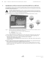
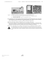
BCnet Sectional Control Panel
Extension
BCE216-3LG
User Manual
©©by
byLabor
MEP -Strauss
Gefahrenmeldetechnik
Sicherungsanlagenbau
GmbH.Ges.m.b.H.
Pockau Wien
Assembly - Connection - Commissioning
Subject to change without notice
2
User Manual BCE216-3LG
Contents
1
1.1
1.2
Introduction . . . . . . . . . . . . . . . . . . . . . . . . . . . . . . . . . . . . . . . . . . . . . . . . . . . . . . . . . . . . . . . . . . . . . . . . . . . . 3
General . . . . . . . . . . . . . . . . . . . . . . . . . . . . . . . . . . . . . . . . . . . . . . . . . . . . . . . . . . . . . . . . . . . . . . . . . . . . . . . . 3
Scope of delivery . . . . . . . . . . . . . . . . . . . . . . . . . . . . . . . . . . . . . . . . . . . . . . . . . . . . . . . . . . . . . . . . . . . . . . . 3
2
Installation in a BCnet Sectional Control Panel BC216-2 or BC216-3 . . . . . . . . . . . . . . . . . 4
3
3.1
3.2
3.2.1
3.3
Connection . . . . . . . . . . . . . . . . . . . . . . . . . . . . . . . . . . . . . . . . . . . . . . . . . . . . . . . . . . . . . . . . . . . . . . . . . . . . . .
Connection of the 24V supply and the loop cables . . . . . . . . . . . . . . . . . . . . . . . . . . . . . . . . . . . . . .
Connection of the GSSnet line . . . . . . . . . . . . . . . . . . . . . . . . . . . . . . . . . . . . . . . . . . . . . . . . . . . . . . . . . .
GSSnet line for a BCnet Sectional Control Panel BC216-2 with installed BCnet
Sectional Control Panel Extension BCE216-3LG . . . . . . . . . . . . . . . . . . . . . . . . . . . . . . . . . . . . . .
GSSnet lines for a BCnet Sectional Control Panel BC216-2 or BC216-3 with installed BCnet Sectional Control Panel Extension BCE216-3LG, which is embedded in a Fire Detection Control Panel BCnet216 . . . . . . . . . . . . . . . . . . . . . . . . . . . . . . . . . . . . . .
Connection of the BCnet redundant alarm line . . . . . . . . . . . . . . . . . . . . . . . . . . . . . . . . . . . . . . . . . .
4
4.1
4.2
4.3
Commissioning . . . . . . . . . . . . . . . . . . . . . . . . . . . . . . . . . . . . . . . . . . . . . . . . . . . . . . . . . . . . . . . . . . . . . . . . . . 9
Firmware version . . . . . . . . . . . . . . . . . . . . . . . . . . . . . . . . . . . . . . . . . . . . . . . . . . . . . . . . . . . . . . . . . . . . . . . 9
Parameter setup . . . . . . . . . . . . . . . . . . . . . . . . . . . . . . . . . . . . . . . . . . . . . . . . . . . . . . . . . . . . . . . . . . . . . . . . 9
Status displays . . . . . . . . . . . . . . . . . . . . . . . . . . . . . . . . . . . . . . . . . . . . . . . . . . . . . . . . . . . . . . . . . . . . . . . . 10
5
Specifications . . . . . . . . . . . . . . . . . . . . . . . . . . . . . . . . . . . . . . . . . . . . . . . . . . . . . . . . . . . . . . . . . . . . . . . . . . 11
3.2.2
6
6
7
7
7
8
All rights reserved. Under the copyright laws, no part of this manual or of the software may be multiplied, copied, disseminated, transferred by phototechnical means, reproduced, translated, or reduced to any electronic medium or machine-readable form, in whole or in part, without the prior written consent of Labor Strauss Sicherungsanlagenbau Ges.m.b.H., Vienna.
The information written in this User Manual has been worked out with the highest care. Neither juridical responsibility nor any kind of liability is taken for
eventually remaining incorrect information. Labor Strauss Sicherungsanlagenbau Ges.m.b.H. reserves the right to change information without notice and
thereby does not take any liability. The pointing out of possible errors in the manual will be gratefully accepted by the authors.
All brand names and product names used in this manual are trade names, service marks, trademarks, or registered trademarks of their respective owners.
B
HB216LGE.SAM / 0342 / AN9161237
ZN5248/11/2
User Manual BCE216-3LG
1
Chapter 1 • Introduction
3
Introduction
The BCnet Sectional Control Panel Extension BCE216-3LG is designed as a compact processing unit
capable of managing 2 loops with System Sensor/500 or Apollo/Discovery protocol. The implementation in a Fire Detection Control Panel BCnet216 is made with the installation of the Extension in a BCnet
Sectional Control Panel BC216-2 or BC216-3 and its connection to the GSSnet wiring via the GSSnet
interface embedded on the Extension.
The 24V supply of the BCnet Sectional Control Panel Extension is taken over by the respective BCnet
Sectional Control Panel in which it has been installed; the Extension has no power supply unit or battery charging unit of its own.
1.1
General
The present User Manual of the BCnet Sectional Control Panel Extension is to be regarded as an addition to the User Manual Series BC216 / Part B. It provides the competent installer with the additional information necessary for the installation of the Extension in a BCnet Sectional Control Panel BC216-2
or BC216-3 and for the connection to the BCnet Sectional Control Panel and to the GSSnet wiring.
The determinations, remarks and explanations stated in the User Manuals of Series BC216 as well as in
the User Manual PARSOFT-2 will not be repeated in the present document! It is therefore indispensable that you familiarize yourself with the contents of these manuals before starting installation, connection and commissioning jobs.
1.2
Scope of delivery
The BCnet Sectional Control Panel Extension BCE216-3LG consists of the following parts:
Loop Gateway Board BCB216-3LG pre-mounted on carrier plate,
24VDC connection cable,
4-pole cable for the GSSnet connection of the Extension with the GSSnet terminals of the Network
Interface NIF5-1 of a BCnet Sectional Control Panel BC216-2 or BC216-3,
hexagon swiveling bolts and further assembly material.
The extension is supplied 100% function-tested. Please check the delivery for completeness and transport damage before installing the equipment.
HB216LGE.SAM / 0342 / AN9161237
ZN5248/11/3
B
4
2
Chapter 2 • Installation in a BCnet Sectional Control Panel BC216-2 or BC216-3
User Manual BCE216-3LG
Installation in a BCnet Sectional Control Panel BC216-2 or BC216-3
All installation work must only be carried out with the respective BCnet Sectional Control Panel in the
de-energized state. Mains power must be switched off and locked to prevent switching on and the standby batteries must be disconnected.
Attention with MOS components! The MOS components employed in the device can be destroyed
by static loads with the device opened. Prior to and during the work carried out on the printed circuit
boards it is necessary to reliably discharge static charges of the body by contacting an earth-connected
metallic part (e.g., the earth-connected Control Panel case).
Remove the case cover according to the instructions in User Manual Series BC216 / Part B.
Figure 1:
Mounting bolts for the installation of the BCnet Sectional Control Panel Extension BCE216-3LG in a
BCnet Sectional Control Panel BC216-2 or BC216-3.
a1 ... hexagon swiveling bolt screwed on hexagon lengthening bolt
a2 ... hexagon bolt
a3 ... hexagon bolt with plastic washer
Further explanations: see the text below.
Remove (and keep for later use) both M3 screws on the right upper and right lower edge of the Power Unit NTB216-1 and install the supplied hexagon swiveling bolts with the lengthening bolts
underneath instead (figure 1/a1). You have to fasten the bolts so tight that
- the Power Unit is fixed sufficiently and
- in swiveled state, the swiveling part of the hexagon bolts form a right angle with the right edge line
of the Power Unit.
Remove (and keep for later use) the remaining M3 screws, which have to be replaced with hexagon
bolts (see figure 2/B), and install the supplied hexagon bolts instead.
If no printed circuit board has been installed on the place where a hexagon bolt has to be screwed,
you have to insert one of the supplied plastic washers underneath the hexagon bolt for level compensation (see figure 1/a3).
B
HB216LGE.SAM / 0342 / AN9161237
ZN5248/11/4
User Manual BCE216-3LG
Figure 2:
Chapter 2 • Installation in a BCnet Sectional Control Panel BC216-2 or BC216-3
5
Installation of the BCnet Sectional Control Panel Extension BCE216-3LG
A ... carrier plate with Loop Gateway Board assembled on the swiveling parts of the
hexagon swiveling bolts
B ... carrier plate fixed with five M3 screws (indicated as circles)
Assemble the carrier plate together with the Loop Gateway Board with the M3 screws removed beforehand (figure 2/A) on both hexagon swiveling bolts (figure 1/a1). Check the smooth working of
the swiveling construction; if necessary, slightly readjust the hexagon bolts.
Fix the carrier plate with the remaining M3 screws according to figure 2/B.
Proceed now with all necessary connection jobs (see from page 6 in Chapter 3: "Connection" and
from page 9 in Chapter 4: "Commissioning"), but keep the mains power switched off and the standby batteries disconnected until all connection jobs have been finished and examined.
Close the Control Panel case according to the instructions in User Manual Series BC216 / Part B.
It is indispensable for the case of the Control Panel to be earthed in operation! For this purpose connect the Control Panel case with the equipotential busbar connection of the local electrical installation. Ensure that protective earth is connected to the earth connection terminal on the bottom part of the
case.
HB216LGE.SAM / 0342 / AN9161237
ZN5248/11/5
B
6
3
Chapter 3 • Connection
User Manual BCE216-3LG
Connection
This chapter generally describes the connection of the usual components of a fire detection system to
the BCnet Sectional Control Panel Extension BCE216-3LG.
Observe the notes stated in the chapter "Connection" of User Manual Series BC216 / Part B! All connection jobs must only be carried out with the respective BCnet Sectional Control Panel in the de-energized state. Mains power must be switched off and locked to prevent switching on and the
stand-by batteries must be disconnected.
The cabling of all connections of the BCnet Sectional Control Panel Extension must be carried out so
that swiveling of the Extension is also possible with all cables connected. Form a slackness loop with
the connection cables on the point of rotation of the Extension BCE216-3LG and fix all cables with
cable binders.
Figure 3:
Position of the connection cables and the slackness loop
A ... power supply cable
B ... loop cables
C ... GSSnet cable
The printed circuit board position of the fuses, connectors, light emitting diodes and other devices mentioned in the following connection schemes are indicated from page 10 in Chapter 4.3: "Status
displays".
3.1
Connection of the 24V supply and the loop cables
The connection cable needed for the connection of the 24V supply is delivered with the BCnet Sectional Control Panel Extension BCE216-3LG. Use the red wires for the positive voltage connection and
the black wires for earth.
+
BCE216-3LG
T2,5A
Si1
1 2 3 4
Loop1
Loop2
L+ LS 1 2 3 4
L+ LS 1 2 3 4
+ _
3 4
F0,8A
Si5
+24V
NTB216-1
Figure 4:
Connection of the 24V supply and the loop cables
terminal 1 + 2 of the loop connections: loop start
terminal 3 + 4 of the loop connections: loop end
If only one of both loops of the Extension shall be used, the respective terminals of the second loop remain unoccupied.
B
HB216LGE.SAM / 0342 / AN9161237
ZN5248/11/6
User Manual BCE216-3LG
Chapter 3 • Connection
7
If shielded cables are used for the loop wiring, you have to attach the shield of only one side of the
circular wiring to the shield terminal "S" of the respective loop connection. Please note the statements
concerning shielded loop cables made in User Manual BC216 / Part B!
The loop connections L+/L- must not be interchanged. It is indispensable that the 2-core line starts on
terminals 1 and 2 and ends on terminals 3 and 4 of the same terminal group as shown in figure 4! The
lines of different loops must not be interconnected anywhere!
3.2
Connection of the GSSnet line
Basically the GSSnet line has to be wired so that the GSSnet output of one GSSnet member (displayed
as ⇓ in the following figure) is connected with the GSSnet input of the next GSSnet member (displayed
as ⇑). Thereby, the GSSnet line forms a closed circle.
3.2.1
GSSnet line for a BCnet Sectional Control Panel BC216-2 with installed BCnet Sectional Control
Panel Extension BCE216-3LG
This device combination forms the smallest Fire Detection Control Panel BCnet216 possible. In this
constellation the GSSnet network entirely remains within the case of the BCnet Sectional Control Panel
BC216-2. The BCnet Sectional Control Panel BC216-2 functions as main operating unit of this device
combination.
BC216-2
BCE216-3LG
GSSnet-Anschlüsse
GSSnet-Terminals
S1 1 2 3 4 S2
S1 1 2 3 4 S2
Figure 5:
GSSnet line between the BCnet Sectional Control Panel BC216-2 and the installed BCnet Sectional
Control Panel Extension BCE216-3LG
The arrows ⇓ and ⇑ show the standard communication direction of the data transfer in the GSSnet.
The GSSnet connection cable for this application is supplied with the BCE216-3LG. Due to the short
length and the fact that the GSSnet line is not led out of the Control Panel case, an unshielded GSSnet
cable may be used.
3.2.2
GSSnet lines for a BCnet Sectional Control Panel BC216-2 or BC216-3 with installed BCnet
Sectional Control Panel Extension BCE216-3LG, which is embedded in a Fire Detection Control
Panel BCnet216
In this constellation, the device combination of a BCnet Sectional Control Panel BC216-2 or BC216-3
and a BCnet Sectional Control Panel Extension BCE216-3LG is by itself again part of a larger Fire Detection Control Panel BCnet216.
HB216LGE.SAM / 0342 / AN9161237
ZN5248/11/7
B
8
Chapter 3 • Connection
User Manual BCE216-3LG
BC216-2, -3
BCE216-3LG
S1 1 2 3 4 S2
Figure 6:
GSSnet-Anschlüsse
GSSnet-Terminals
S1 1 2 3 4 S2
BCnet Sectional Control Panel BC216-2 or BC216-3 with installed BCnet Sectional Control Panel
Extension BCE216-3LG, included in a Fire Detection Control Panel BCnet216.
The arrows ⇓ and ⇑ show the standard communication direction of the data transfer in the GSSnet.
The supplied unshielded cable may be used for the GSSnet line between the BC216-2 or BC216-3 and
the installed BCE216-3LG (see also from page 7 in Chapter 3.2.1: "GSSnet line for a BCnet Sectional
Control Panel BC216-2 with installed BCnet Sectional Control Panel Extension BCE216-3LG"). For
the GSSnet lines leading outside to the remaining BCnet Sectional Control Panels, the use of category 5
computer network cable is inevitable. Observe the correct connection of the shields of the network
cable (see User Manual Series BC216 / Part B).
3.3
Connection of the BCnet redundant alarm line
A potential-separated semiconductor switch with integrated serial resistor is provided on the BCnet
Sectional Control Panel Extension BCE216-3LG for activating the redundant alarm function.
BC216-2, -3
A
B
5 6 7 8
16 17
1)...Depending on the outfit of the BCnet Sectional Control Panel, either the contact of the alarm relay of the Power Unit
NTB216-1 or the contact of the relay HM1 on the Fire Brigade Interface FWI2-1.
Figure 7:
Connection of the BCnet redundant alarm line to the BCnet Sectional Control Panel Extension
BCE216-3LG
A ... BCnet Sectional Control Panel to which the transmitting device to the fire brigade is connected
B ... BCnet Sectional Control Panel with installed extension BCE216-3LG
The semiconductor switch acting on terminals 16 and 17 is polarity dependent. It has to be connected to
the Network Redundant Alarm Converter NNU5-1, which is installed in the BCnet Sectional Control
Panel to which the transmitting device to the fire brigade is connected, in exactly the illustrated way.
Convince yourself during commissioning of the Fire Detection Control Panel that also the redundant
alarm function works correctly!
Upon alarm of a detector connected to the BCE216-3LG, the voltage on the terminals 16 and 17 decreases from approximately 10V to approximately 2V (at 24V supply voltage); successively, the
alarm criteria (= 0V) is put out on terminal 4 of the NNU5-1.
B
HB216LGE.SAM / 0342 / AN9161237
ZN5248/11/8
User Manual BCE216-3LG
4
Chapter 4 • Commissioning
9
Commissioning
Prior to commissioning of the Control Panel, follow the checklist below and check the following points
in correspondence to the existing Control Panel structure:
Is the supply voltage of the Extension properly connected?
Are the incoming and the outgoing network cable properly connected?
Is the network cable as a whole laid as a circle without branch-offs?
Are the shielding wires of the incoming and the outgoing network cables isolated from each other
and connected to the correct terminals?
Is the network redundant alarm line properly connected?
Are the loops properly connected?
Are all addresses of the devices connected to the loop set correctly?
Are all detectors in normal condition?
Check once again the earth-connection of the Control Panel case: The cover and bottom part must be
electrically interconnected during operation.
Check if all mounting screws of the inserted boards are securely tightened. This is particularly decisive for the effectiveness of the EMC measures taken on the boards.
Proceed commissioning according to the steps described in User Manual Series BC216 / Part B.
4.1
Firmware version
The same firmware version must be installed in the BCnet Sectional Control Panel Extension
BCE216-3LG as is in all other Sectional Control Panels of the Fire Detection Control Panel BCnet216.
This is valid also if the Control Panel exists of only one BC216-2 and a BCE216-3LG installed therein.
If the firmware versions do not match, you have to adjust the firmware of the Extension to the firmware
version of the remaining BCnet Sectional Control Panels. To install a new firmware version, plug a Serial Interface Module SIM216-1 to the connector ST2 of the BCE216-3LG (see figure 8), screw it on
tightly and then transfer the new firmware via PC and PARSOFT-2 to the BCE216-3LG.
The BCnet Sectional Control Panel Extension BCE216-3LG is only operative with a firmware starting PL149Vx.15!
Alternatively, it can be useful to equip the existing BCnet Sectional Control Panels with the firmware
version which is installed in the BCE216-3LG - or to equip the existing Sectional Control Panels and
the Extension with the latest firmware version.
The procedure for the transmission of a firmware from the PC to the Control Panel is described in User
Manual PARSOFT-2.
For the first firmware update the BCnet Sectional Control Panel Extension must be handled like a
stand-alone Control Panel BC216-1. If the BCnet Sectional Control Panel Extension is already part of
a BCnet216, updates of the firmware are executed for all Sectional Control Panels together from the
main operating unit of the BCnet216.
The firmware version is indicated on the packing of the Extension. You can also read out the current
firmware version of the Extension via PARSOFT-2 (see User Manual PARSOFT-2).
4.2
Parameter setup
The BCnet Sectional Control Panel Extension is supplied without works settings. Thus you have to set
up the necessary configuration by individual parameterization during commissioning. You proceed parameterization via a PC and Parameter Setup Software PARSOFT-2 on the main operating unit of the
ready-wired Fire Detection Control Panel BCnet216 (see User Manual Series BC216 / Part C and User
Manual PARSOFT-2).
HB216LGE.SAM / 0342 / AN9161237
ZN5248/11/9
B
10
4.3
Chapter 4 • Commissioning
User Manual BCE216-3LG
Status displays
Two LEDs (D16 and D27) are available on the BCnet Sectional Control Panel Extension BCE216-3LG
which provide - in addition to the displays of the respective Sectional Control Panel or of the main operating unit - a status display.
Figure 8: Survey of the components of the printed circuit board of the BCnet Sectional Control Panel
Extension BCE216-3LG
D16, D27 . . . light emitting diodes for status display
TA1 . . . . . . . . RESET button
JP1 . . . . . . . . . short circuit connector for initializing the firmware update
ST2 . . . . . . . . . connector for attaching a Serial Interface Module SIM216-1
Si1 . . . . . . . . . fuse for the supply voltage
The light emitting diodes display the following conditions:
Light emitting diode D16 (green):
illuminated: the BCE216-3LG works normally
flashing:
the BCE216-3LG is in redundant operating mode
The processor system works only restrictedly, the GSSnet data line is not supported, the
two loops are - provided they are not themselves impaired by the fault - entirely supported; a possible alarm is proceeded via the redundant alarm output.
This condition is displayed as member fault on the connected BCnet Sectional Control
Panels with display and operating unit
dark:
the BCE216-3LG is either de-energized or in the condition "system fault"
Depending on the cause of the fault, the BCE216-3LG is either completely out of
function or it attempts to maintain a redundant operation of the two loops; a possible
alarm is proceeded via the redundant alarm output.
This condition is displayed as member fault on the connected BCnet Sectional Control
Panels with display and operating unit
Light emitting diode D27 (red):
flickering: data is received via the GSSnet
dark:
either no data is received via the GSSnet or the BCE216-3LG is de-energized
B
HB216LGE.SAM / 0342 / AN9161237
ZN5248/11/10
User Manual BCE216-3LG
5
Chapter 5 • Specifications
11
Specifications
Please also refer to the specifications and other notes provided in User Manual Series BC216 / Part B.
Supply voltage
21-30VDC (from the BCnet Sectional Control Panel)
Power consumption at 24V (w/o detectors, modules) typ. 140mA
Number of loops
Number of detector zones per loop
Total number of detector zones of both loops
Number of detectors, modules per loop
System Sensor/500
Apollo/Discovery
Loop quiescent current
Loop total current (detectors, modules, sirens etc.)
Loop quiescent voltage
Loop line
Line resistance
Line capacity
Connection type
Wire cross section
max. 198 elements (99 detectors + 99 modules)
max. 126 elements
typ. 300µA per connected detector or module
max. 300mA (at reduced line resistance)
typ. 26V (Apollo) or 29V (System Sensor)
2-core, shielded or unshielded
max. 50Ω per core
max. 400nF
screw terminals
max. 2.5mm² (single wire)
GSSnet connection
Cable length between two GSSnet members
Connection type
Wire cross section
RS485, galvanically separated
max. 1200m (category 5 network cable)
screw terminals
max. 2.5mm² (single wire)
Ambient temperature
Relative humidity of air
Dimensions l × w × h
Weight incl. carrier plate
-5°C to +50°C
95% (non-condensing)
248 × 222 × 28 (mm)
approx. 675g
HB216LGE.SAM / 0342 / AN9161237
ZN5248/11/11
B
2
max. 128
max. 144