1
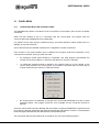
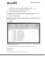
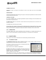
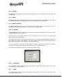
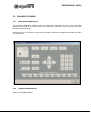
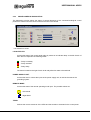
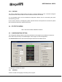
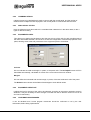
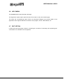
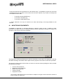
ALGORITHMIC SYSTEM
AGE41
COMMISSIONING
VERSION 1.1
MAR/05
USER MANUAL AGE41
CONTENTS.
1
THE START-UP PROGRAM. ................................................................................... 3
2
MAIN MENU.............................................................................................................. 4
2.1
PANEL MENU. ............................................................................................................................................5
2.1.1
CONNECTION WITH THE CONTROL PANEL. .....................................................................5
2.1.2
DISCONNECTION WITH THE CONTROL PANEL. ...............................................................6
2.1.3
RESET THE CONTROL PANEL. ............................................................................................6
2.1.4
REPORTS. ..............................................................................................................................6
2.1.5
CLEAR EVENTS. ....................................................................................................................7
2.2
CHANNEL MENU. ......................................................................................................................................7
2.2.1
EQUIPMENTS RANGE. ..........................................................................................................7
2.2.2
EXPORT. .................................................................................................................................8
2.2.3
RESET.....................................................................................................................................8
2.2.4
RESET OUTPUTS...................................................................................................................8
2.2.5
R OUTPUT. .............................................................................................................................8
2.2.6
– PREVIOUS. ..........................................................................................................................8
2.2.7
+ NEXT. ...................................................................................................................................8
2.3
DIAGNOSTICS MENU...............................................................................................................................9
2.3.1
KEYBOARD DIAGNOSTICS...................................................................................................9
2.3.2
CHANNEL DIAGNOSTICS......................................................................................................9
2.3.3
MISCELLANEOUS DIAGNOSTICS. .....................................................................................10
2.3.4
FACTORY..............................................................................................................................11
2.4
STATISTICS MENU. ................................................................................................................................11
2.5
CONFIGURATION OPTION. ..................................................................................................................11
2.5.1
GENERAL..............................................................................................................................11
2.5.2
COMMUNICATIONS. ............................................................................................................12
2.5.3
ANALOGICAL LEVELS. ........................................................................................................12
2.5.4
EQUIPMENTS AREA. ...........................................................................................................12
2.5.5
EQUIPMENT AREA FONT....................................................................................................12
2.5.6
CONFIRMATION MESSAGES..............................................................................................12
2.6
HELP MENU..............................................................................................................................................13
2.7
EXIT OPTION............................................................................................................................................13
3
TOOLBAR............................................................................................................... 14
4
EQUIPMENT PANEL. ............................................................................................. 15
4.1
MONITORING EQUIPMENTS................................................................................................................16
5
STATUS LINE......................................................................................................... 18
6
TROUBLESHOOTING. ........................................................................................... 19
Ae-man-804-0.0 v1.1
2
AGUILERA ELECTRONICA
USER MANUAL AGE41
1 THE START-UP PROGRAM.
The purpose of this program is to facilitate the commissioning and maintenance of the installations
based on the analogical control panels AE/SA-C2, AE/SA-C8, AE/SA-C23H and AE/SA-C83H.
In this respect it allows us:
To determine what items of equipment are connected to a control panel
•
•
•
•
•
•
To check that these items work correctly.
To act on the outputs of these items.
To export the structure of the channels to files that the AGE42 customiser will be able to read
later.
To obtain information of the incidents that occur in the installation.
To monitor the general maneuver of the control panel, by means of diagnostics.
To reboot and download the statistical information stored in the control panel.
In brief, the program allows the state of an installation to be checked without needing to have the
control panels personalized.
Ae-man-804-0.0 v1.1
3
AGUILERA ELECTRONICA
USER MANUAL AGE41
2 MAIN MENU.
The main menu provides access to the different functions of the program, which are organized in the
following way:
•
o
Control Panel.
o
Connect.
o
Disconnect.
o
Reboot.
o
Listings.
o
Delete incidents.
o
Channel.
o
Range of equipment.
o
Export.
o
Reboot.
o
Restore outputs.
o
Output R.
o
Preceding.
o
Following.
o
Diagnostics.
o
Keyboard.
o
Channels.
o
Miscellaneous.
o
Factory.
o
Statistics.
o
Download.
o
Reboot.
Configuration.
o
Help.
o
Content.
o
About Start-up.
o
Exit.
Ae-man-804-0.0 v1.1
4
AGUILERA ELECTRONICA
USER MANUAL AGE41
2.1
PANEL MENU.
2.1.1
CONNECTION WITH THE CONTROL PANEL.
The Connect option allows a connection to be set up with the control panel, when we are not already
connected.
When the user decides to set up a connection with the control panel, the program uses the
communications port established in the configuration.
If a problem occurs when trying to initialize this port, we will be allowed to select another port in a
dialogue to retry the maneuver.
In this case the new port selected is preset in the configuration for later connections.
Once access to the communications port is obtained, the program performs the detection of the
control panel connected. Three (3) cases can arise:
•
An analogical control panel AE/SA-C2 is detected. The fixed program automatically the
number of line control cards at 1, that which will allow us to monitor 2 channels.
•
An AE/SA-C8 analogical panel is detected. The program asks us for the number of line
control cards present in the control panel. The number of channels that we will be able to
monitor will be twice the number of cards we indicate.
•
No control panel is not detected, or the type of the control panel detected is not any of those
mentioned above. The program issues an error message and the connection process is
aborted.
Once the control panel has been detected and the number of channels established to which there will
be access, the program selects the first channel automatically and begins to monitor it. The equipment
panel will begin to be filled with the data that the control panel reports.
The connection with the control panel can conclude for any one of the following reasons:
Ae-man-804-0.0 v1.1
5
AGUILERA ELECTRONICA
USER MANUAL AGE41
•
•
•
2.1.2
At the request of the user, when he decides to conclude the connection.
At the request of the user, when he decides to close the program while connected.
When communication is lost with the analogical control panel.
DISCONNECTION WITH THE CONTROL PANEL.
The Disconnect option allows the current connection with the control panel to be concluded, if any.
We will be requested for confirmation beforehand, if so indicated in the configuration.
2.1.3
RESET THE CONTROL PANEL.
The Reset option forces the control panel to resend the information of all its equipment, the same as
is done when setting up the connection. We will be requested for confirmation beforehand, if so
indicated in the configuration.
2.1.4
REPORTS.
The Reports option opens a dialogue in which we can generate reports of equipment, levels and
incidents for one or more channels.
This dialogue allows the different reports that the program can generate to be managed.
It is divided in 4 zones.
TYPE SELECTOR.
It allows the type of report to be selected that we want to generate.
Ae-man-804-0.0 v1.1
6
AGUILERA ELECTRONICA
USER MANUAL AGE41
CHANNEL SELECTOR.
It allows the scope of the report to be defined. For this we can select one or all of the available
channels.
PREVIEW ZONE.
It shows the reports that we are producing. Every time a new report is generated, its content is erased,
so that the previous report is lost.
CONTROL BUTTONS.
By clicking the Report button, the program generates the report according to the active selectors and
downloads it to the preview zone.
The Save button allows us to send the current content from the preview zone to a text file in the
location we indicate.
The Finish button closes the reports window.
The information that is used to produce a report is obtained from the current connection, if any, or from
the last connection carried out in the session if we are disconnected. Whenever a new connection is
set up, all the information on equipment, levels and incidents is rebooted, in other words it is lost.
2.1.5
CLEAR EVENTS.
The Clear events option reboots (eliminates) all the information on incidents stored during the
session. We will be requested for confirmation beforehand, if so indicated in the configuration.
2.2
CHANNEL MENU.
All the options of this menu are executed on the channel being monitored at the time.
2.2.1
EQUIPMENTS RANGE.
The Equipments range option opens a dialogue in which we will be able to define the range of
equipment which the control panel should poll for its status.
The range of a channel is the set of items of equipment with which
the panel attempts to communicate.
Each channel can have a different range defined.
By default, when setting up a connection, the range of items of all
the channels covers the 125 possible items. Once all the items are
installed and their numbering verified, we can redefine these
ranges, to speed up communications.
When defining a new range in the selected channel, the changes made are reflected immediately in
the items panel. The new range is kept until it is redefined or until the current connection is concluded.
Ae-man-804-0.0 v1.1
7
AGUILERA ELECTRONICA
USER MANUAL AGE41
2.2.2
EXPORT.
The Export option allows the channel to be downloaded to a file (*.cnl) that the customiser will be able
to import later.
2.2.3
RESET.
The Reset option forces the control panel to resend us the information of all the items of the channel.
We will be requested for confirmation beforehand, if so indicated in the configuration.
2.2.4
RESET OUTPUTS.
The Reset outputs option forces the reset of all the channel outputs and synoptics. We will be
requested for confirmation beforehand, if so indicated in the configuration.
2.2.5
R OUTPUT.
The R Output option opens a dialogue that allows a timed test to be defined for the R output of all the
analogical detectors of the channel.
This test allows us to visually check the correct maneuver of the R output for all the analogical
detectors of the channel selected.
The program will request us for a delay time, and once this is entered, a timed activation sequence of
the R output will begin in each detector. The delay indicates the time that each R output remains
active before being restored and passing to the following detector.
If we try to initiate an R output test while another is already under way, the program will request
confirmation to conclude it beforehand, since both cannot be run simultaneously.
The progress of the test will be shown in the status line while it lasts.
2.2.6
– PREVIOUS.
The “- Previous” option passes to monitor the preceding channel of the control panel. You can also
run this option by pressing the key “-“.
2.2.7
+ NEXT.
The “+ Next” option passes to monitor the following channel of the control panel. You can also run this
option by pressing the key “+”.
Ae-man-804-0.0 v1.1
8
AGUILERA ELECTRONICA
USER MANUAL AGE41
2.3
2.3.1
DIAGNOSTICS MENU.
KEYBOARD DIAGNOSTICS.
The keyboard diagnostics window shows an image that represents the front of the connected
analogical control panel, and it allows the correct maneuver of all the keys to be checked, as well as
that of the access level key.
Pressing any key on the panel, or when the key position is altered, the diagnostics window will reflect
it in visual terms.
2.3.2
CHANNEL DIAGNOSTICS.
ONLY FOR 2-WIRE PANELS.
Ae-man-804-0.0 v1.1
9
AGUILERA ELECTRONICA
USER MANUAL AGE41
2.3.3
MISCELLANEOUS DIAGNOSTICS.
The diagnostics window allows the status of several elements of the connected analogical control
panel to be checked and the correct maneuver thereof to be verified.
It is divided in 4 zones.
LOCAL RELAYS.
It shows the state of the control panel relays by means of an indicator lamp on the left of each of
them that can represent the following states:
- Relay in standby.
- Relay actuated.
- Relay faulty.
The button located to the right of each local relay allows its state to be switched.
POWER SUPPLY UNIT.
It shows the level in volts at the inputs of the power supply unit, as well as the state of the
grounding system.
REMOTE MODE.
It shows the state of the remote operating mode input. The possible values are:
- DAY Mode.
- Night Mode.
TESTS.
It allows the correct maneuver of the LEDs and the sounder to be tested in the control panel.
Ae-man-804-0.0 v1.1
10
AGUILERA ELECTRONICA
USER MANUAL AGE41
2.3.4
FACTORY.
The factory diagnostics window allows the state of several elements of the connected analogical
control panel to be checked and the correct maneuver thereof to be verified.
It is an expanded version of the miscellaneous diagnostics window, and it is used during the panel
manufacturing process.
For its correct maneuver, this diagnosis system requires that the control panel be connected to special
test hardware developed by Aguilera Electrónica.
2.4
STATISTICS MENU.
ONLY FOR THE 2-WIRE CONTROL PANELS
2.5
CONFIGURATION OPTION.
The configuration dialogue allows maneuver parameters of the program to be defined, the values of
which will be kept until they are modified again, even though we close the application.
The Predetermined button reboots all the dialogue fields with their default values.
This dialogue is divided in 6 zones.
2.5.1
GENERAL.
It allows to select the language of handling of the program.
Ae-man-804-0.0 v1.1
11
AGUILERA ELECTRONICA
USER MANUAL AGE41
2.5.2
COMMUNICATIONS.
It allows the port to be defined that is used to connect with the control panel, and the number of
retries and the multiplier thereof employed in the control panel to communicate with the items.
2.5.3
ANALOGICAL LEVELS.
Here we define the level above which it is considered that a detector is in the alarm state, for the 3
types of detector existing.
2.5.4
EQUIPMENTS AREA.
This allows us to define the background and the text colours of the cells for each possible state of
the items associated therewith, as well as to access the configuration of advanced properties of the
panel, allowing some advanced parameters of the equipment panel to be defined:
Cell size.
We can indicate the width and height, in pixels, of the panel cells. The Self-adjust button will fill in
these data automatically, calculated on a basis of the current size of the main window.
Margins.
We can define the horizontal and vertical margin, in pixels, of the text inside each cell of the panel.
The Default button reboots all the fields of the dialogue to their default values.
2.5.5
EQUIPMENT AREA FONT.
It allows the font for the text of the cells to be selected. According to the screen resolution preset in
Windows, it may be necessary to select a larger or smaller font size so that the cell text is not cut off
and can be read clearly.
2.5.6
CONFIRMATION MESSAGES.
It can be decided here if some program maneuvers should be confirmed or not by the user
beforehand, before being implemented.
Ae-man-804-0.0 v1.1
12
AGUILERA ELECTRONICA
USER MANUAL AGE41
2.6
HELP MENU.
The Contents option opens the help main page.
The Algorithmic System option opens the help for the same on the main contents page.
The About the commissioning option shows an informative dialogue with several details of the
application and of Aguilera Electrónica: Names of the program, version, Web address, etc.
2.7
EXIT OPTION.
It closes the start-up program in March, concluding the connection if necessary and requesting prior
confirmation if so indicated in the configuration.
Ae-man-804-0.0 v1.1
13
AGUILERA ELECTRONICA
USER MANUAL AGE41
3
TOOLBAR.
It contains a series of buttons with icons that provide shortcuts to the functions most frequently used.
Button What it does
If we are not connected, it tries to set up a connection. Otherwise, the connection is
concluded.
It reboots the control panel.
It reboots the current channel.
It restores the outputs and synoptics of the current channel.
It selects channel 1.
It selects channel 2.
It selects channel 3.
It selects channel 4.
It selects channel 5.
It selects channel 6.
It selects channel 7.
It selects channel 8.
It opens the help index.
It closes the Start-up program.
The buttons to Reboot panel, Reboot channel and Restore outputs will only be available during the
connection, the same as their corresponding menu options.
The channel selectors will also only be available during the connection, and depending additionally on
the associated channel being present in the control panel, according to its number of line control
cards.
If, for example, we connect to an AE/SA-C8 panel with 3 line control cards, the first 6 selectors will be
enabled and the last 2 not (3 cards = 6 channels).
Ae-man-804-0.0 v1.1
14
AGUILERA ELECTRONICA
USER MANUAL AGE41
4 EQUIPMENT PANEL.
This is a matrix of 16 rows by 8 columns, in which the items of the monitored channel are shown when
we are connected.
Each cell (*) of the matrix corresponds to an item of equipment, and it shows us the number, type and
status of the same.
(*) The matrix has 16 x 8 = 128 cells, and one channel admits a maximum of 125 items. Therefore the
last 3 cells have no use and will always be empty.
ITEM NUMBER.
A number between 1 and 125 is shown in the left part of the cell, which indicates the position of the
item in the channel.
TYPE OF ITEM.
A reference is shown in the right part of the cell, which indicates the type of item detected in that
position.
In the positions in which no item responds, no reference is shown: we will only see the item number.
If instead of a reference we see the text "[MULTIPLE]", it means that there is a conflict of multiple
items in this channel address.
MULTIPLE ITEMS.
ONLY FOR THE 2-WIRE CONTROL PANELS.
If two or more items of a channel are coded with the same address, a conflicting situation is
produced that the line control is able to detect and report to the Start-up program.
So that this situation is always correctly detected, the addresses of the items should not be
changed with the system hot. In the event of having to do so, we will have to reboot the
channel or channels involved so that the program requests the panel again for recent
information on the types of item detected.
STATUS OF THE ITEM.
The colour used to show the number and the type of equipment in the cell informs us of its
status, according to the code that was defined in the configuration dialogue.
Each of cells of the matrix can be selected with the cursor movement keys or by clicking on it with the
mouse.
Ae-man-804-0.0 v1.1
15
AGUILERA ELECTRONICA
USER MANUAL AGE41
Three (3) maneuvers can be carried out on this selected cell (*), accessible by means of a menu that
is deployed with the right button of the mouse over the cell in question or by means of the keys that
are indicated in each case:
-
To monitor the item (ENTER key).
To convert to null (DEL key).
To convert to valid (INSERT key).
(*) These maneuvers can only be carried out on items that belong to the range defined for the
channel.
4.1
MONITORING EQUIPMENTS.
To monitor an equipment, a monitoring dialogue is opened in which we see, in addition to other
information, the state of the item in detail and we also have the possibility of acting on its outputs and
synoptics in the cases in which this is possible.
The Equipment monitoring windows give real time information on the state of an equipment , and they
also allow switching of the state of their outputs and/or synoptics in the cases in which this is possible.
The structure of the top part of the window is common for all the monitoring dialogues, and it provides
the following information:
•
•
•
•
•
Picture of the equipment.
Reference of the equipment.
Name of the equipment.
Channel number.
Equipment number.
The content of the bottom part of the window is subject to the type of item monitored: number of
inputs, number of outputs, etc.
Ae-man-804-0.0 v1.1
16
AGUILERA ELECTRONICA
USER MANUAL AGE41
In general, the following rules are followed:
The inputs are shown by means of two texts: one that describes the input and
another that indicates its state. The latter will also appear collared, depending on
the state of the input.
The state of the outputs and the synoptics are shown by means of an indicator to
the left of the text of the same. The possible states are:
- Output or synoptic in standby.
- Output or synoptic actuated.
The button located to the right of the outputs/synoptics allows their state to be
switched.
Other informative elements can appear: analogical levels, etc.
A monitoring window can be closed for any of the following reasons:
•
•
•
•
At the request of the user, by means of the Close button or the ESCAPE key.
If it is detected that the type of item has changed that occupies that position in the
channel.
If the item stops communicating with the control panel.
If the connection with the control panel is lost.
The maneuver of converting an equipment to null forces the type of item in the selected cell to null,
and has the purpose of creating gaps in the channel to be clarified, visually, that in a certain position
there really is no item present, and not that there is an item that is not responding.
The maneuver of converting to valid is the reverse of the preceding one, and it is only applicable
when the item of the selected cell is null. In this case, the type of item is forced to "None" so that if
there is an item in that position that responds correctly to the control panel, in few seconds the cell will
be updated with the type of item detected.
Ae-man-804-0.0 v1.1
17
AGUILERA ELECTRONICA
USER MANUAL AGE41
5
STATUS LINE.
It informs us of the state of some parameters of the current connection.
It is divided in 5 zones:
CHANNEL.
It indicates the number of the selected channel.
EVENTS.
It shows the number of events that have taken place in the selected channel, as well as the
total number of events (the sum of all the channels).
RANGE.
It shows the defined range of items for the selected channel.
PROGRESS OF THE R OUTPUT TEST.
If there is a test of the R output in course, it shows the number of the channel involved, as well
as the number of the item under test at the moment.
EQUIPMENTS SELECTED.
It informs of the number of the items corresponding to the cell selected in the panel. If the item
is valid, it also shows its reference and a brief descriptive text of the item type.
If no connection is set up, all the segments of the status line will appear empty.
Ae-man-804-0.0 v1.1
18
AGUILERA ELECTRONICA
USER MANUAL AGE41
6 TROUBLESHOOTING.
The messages that are shown below appear if errors occur when running the program.
If you still cannot resolve the problem, note down the error code in brackets, the additional information
that is provided (filenames, other messages, etc.), and contact Aguilera Electrónica.
[100]: Error in file.
[101]: The field cannot be empty.
[102] : Erroneous value. Valid range = [MINIMUM .. MAXIMUM].
[103]: The initial item cannot come after the final item.
[104]: You cannot monitor an item that does not communicate.
[105]: The type of item has changed.
[106]: The item has stopped communicating with the control panel.
[107]: There is no listing to save.
[108]: The port [NUMBER PORT] cannot be opened.
[109]: Cannot connect with the control panel.
[110]: Control panel type not supported.
[111]: The number of control panel cards could not be fixed.
[112]: Parameters could not be fixed in the control panel.
[113]: The connection has been lost with the control panel.
Ae-man-804-0.0 v1.1
19
AGUILERA ELECTRONICA
NORTHEAST BRANCH OFFICE
YOUR NEAREST SUPPORT AND SUPPLY POINT
HEAD OFFICES
C/ Julián Camarillo, 26 – 2ª Planta – 28037 Madrid – Tel: 91 754 55 11 – Fax: 91 754 50 98
GAS TREATMENT FACTORY
Av. Alfonso Peña Boeuf, 6. Pol. Ind. Fin de Semana – 28022 Madrid – Tel: 91 754 55 11 – Fax: 91 329 58 20
NORTHEAST BRANCH OFFICE
C/ Rafael de Casanovas, 7 y 9.- SANT ADRIA DEL BESOS – 08930 Barcelona
Tel: 93 381 08 04 – Fax: 93 381 07 58
NORTHWEST BRANCH OFFICE
C/ José Luis Bugallal Marchesi, 9, 1ºB – 15008 A Coruña – Tel: 98 114 02 42 – Fax: 98 114 24 62
SOUTH BRANCH OFFICE
Av. San Francisco Javier,9. Edificio Sevilla II, 2ª Planta. Módulo 7 - 41018 Sevilla
Tel: 95 465 65 88 – Fax: 95 465 71 71
CANARY ISLAND BRANCH OFFICE
C/ Sao Paolo, 17, 2ª Planta. Oficina 3-2-15. Urb. Ind. El Sebadal – 35008 Las Palmas de Gran Canarias
Tel: 928 24 45 80 – Fax: 928 24 65 72
www.aguileraelectronica.es
e-mail: [email protected]