1
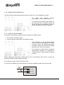
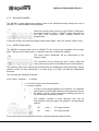
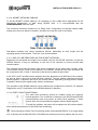
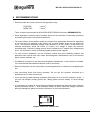
ALGORITHMIC PANEL
AE/SA-C1
INSTALLATION GUIDE
VERSION 1.0
SEP/11
INSTALLATION GUIDE AE/SA-C1
TABLE OF CONTENTS
PAGE
1
INTRODUCTION....................................................................................................... 5
1.1
1.2
1.3
1.4
2
CONTENTS. MATERIAL INCLUDED IN THE PACK. ............................................... 7
2.1
2.2
3
AIM OF THE GUIDE. ...........................................................................................................5
OBSERVATIONS. ..............................................................................................................5
WARNINGS AND PRECAUTIONS. .........................................................................................5
APPROVALS. ....................................................................................................................5
CHECKING THE PANEL. .....................................................................................................7
MATERIAL........................................................................................................................7
INSTALLATION......................................................................................................... 9
3.1 PANEL LOCATION. ............................................................................................................9
3.1.1 Dimensions and attachment points. .........................................................................9
3.1.2 Cabinet attachement..............................................................................................11
3.1.3 Removal of the base plate. ....................................................................................13
3.1.4 Removal of the power source. ...............................................................................13
3.2 PARTS OF THE PANEL.....................................................................................................13
3.2.1 Front plate. ............................................................................................................13
3.2.2 Base plate. ............................................................................................................13
3.2.3 Power source. .......................................................................................................13
3.2.4 Backup batteries....................................................................................................13
3.3 CONNECTIONS TO EXTERNAL CIRCUITS. ..........................................................................14
3.3.1 230V mains power.................................................................................................14
3.3.2 Batteries. ...............................................................................................................16
3.3.3 24V Auxiliary power output. ...................................................................................17
3.3.4 remote Disconnection. ...........................................................................................18
3.3.5 Evacuation sounder...............................................................................................18
3.3.6 General relays. ......................................................................................................19
3.3.7 Day/night modes....................................................................................................20
3.3.8 Detection loops......................................................................................................20
3.3.9 RS-232 and RS-485 Communication ports. ...........................................................21
3.3.10
AE2NET network cabling....................................................................................22
3.3.11
End of line resistors on the AE2NET network. ....................................................22
3.3.12
Earth fault monitoring. ........................................................................................22
4
RECOMMENDATIONS ........................................................................................... 23
5
PUTTING THE PANEL INTO SERVICE.................................................................. 25
5.1 CPU MICROSWITCH CONFIGURATION. .............................................................................25
5.2 STARTING UP THE FACILITY. ............................................................................................27
5.2.1 lenguaje.................................................................................................................28
5.2.2 Led test. ................................................................................................................28
5.2.3 Clock setup............................................................................................................28
5.2.4 Startup mode.........................................................................................................29
Ae-man-851-0.0 v1.0
3
AGUILERA ELECTRONICA
INSTALLATION GUIDE AE/SA-C1
5.2.5 Network diagnostics. ............................................................................................. 31
5.3 VERIFICATION OF THE AE2NET NETWORK’S OPERATION. ................................................ 32
5.3.1 Synchronisation..................................................................................................... 32
5.3.2 At rest. .................................................................................................................. 32
5.3.3 Active. ................................................................................................................... 33
5.3.4 Fault resetting. ...................................................................................................... 34
5.3.5 Equipment programming mode. ............................................................................ 34
5.4 STARTUP USING A PC WITH AGE41 SOFTWARE. ............................................................. 35
5.5 CUSTOMISATION OF THE FACILITY. .................................................................................. 36
6
CONSUMPTION (BATTERY CALCULATION). ...................................................... 37
6.1 PROCEDURE FOR BATTERY CALCULATION. ...................................................................... 37
6.1.1 Duration. ............................................................................................................... 37
6.1.2 Capacity calculation. ............................................................................................. 37
7
MAINTENANCE...................................................................................................... 39
7.1.1
7.1.2
8
Periodical operations............................................................................................. 39
Service life of main components............................................................................ 39
SPECIFICATIONS. ................................................................................................. 41
INSTALLATION REGISTRATION FORM. .................................................................... 45
Ae-man-851-0.0 v1.0
4
AGUILERA ELECTRONICA
INSTALLATION GUIDE AE/SA-C1
1
INTRODUCTION.
1.1
AIM OF THE GUIDE.
The aim of this guide is to provide the user with all the descriptions of recommended
procedures and technical details in order to install and start up the AE/SA-C1 Algorithmic Fire
Detection Control Panel.
The procedures described in this guide include advice and warnings so that the user adopts
methodical, safe working practices during installation and startup.
1.2
OBSERVATIONS.
•
•
1.3
The following guide is only valid for the connection and startup of the AE/SA-C1
panel. For other panel models, check the appropriate guide.
The manufacturer reserves the right to change, modify or correct the information
without prior notification.
WARNINGS AND PRECAUTIONS.
The installer of the panel and devices that make up the Fire Detection System must be
authorised and trained in both handling of the panel and the current legislation.
Before connecting any devices, check that the panel’s power supply is disconnected.
The user should read this guide and understand its contents before undertaking any tasks
related to the AE/SA-C1 Algorithmic Panel. If you have any doubts about any aspects covered
by the guide, check with the supplier before beginning installation and startup.
1.4
APPROVALS.
The control panel has been designed in accordance with:
Standards EN54-2 and EN54-4, in terms of both compulsory functions and some optional
functions that have certain requirements.
EU Electromagnetic Compatibility Directive 2004/108/EC.
EU Low Voltage Compatibility Directive 2006/106/EC.
Some of the panel’s functions can be set up to make it more effective, increasing the device’s
possibilities and performance. These are not covered by standard EN54, and therefore, if used,
would not comply with this standard.
When it is possible that a connection or configuration that does not comply with the regulations
can be carried out, this will be indicated, with a brief explanation of the requirements set out in
standard EN54.
Ae-man-851-0.0 v1.0
5
AGUILERA ELECTRONICA
INSTALLATION GUIDE AE/SA-C1
Aguilera Electrónica S.L.
C/Julián Camarillo 26 - 28037 MADRID - SPAIN
10
0099/CPD/A74/0159
AE/SA-C1 ALGORITHMIC FIRE DETECTION CONTROL PANEL
EN 54-2:1997/A1:2006
Control and communication device for fire detection and alarm systems for buildings.
EN54-4:1997/A2:2006
Power supply device for fire detection and alarm systems for buildings.
Optional functions with requirements:
•
Output for fire alarm devices
•
Dependencies on more than one alarm signal. Type-C dependency
•
Point failure signals
•
Total loss of power supply
•
Disconnection of addressable points
Technical data: see the documents provided by the manufacturer.
• Installation Guide. Document Ae-man-851-0-0
• User Guide. Document Ae-man-803-0.0
Ae-man-851-0.0 v1.0
6
AGUILERA ELECTRONICA
INSTALLATION GUIDE AE/SA-C1
2 CONTENTS. MATERIAL INCLUDED IN THE PACK.
2.1
CHECKING THE PANEL.
It is important to carry out a visual inspection to see that the equipment supplied has not
suffered any damage, before starting to install it. If you observe any problems, IT SHOULD NOT
be installed; please contact the supplier.
2.2
MATERIAL.
The box contains the panel and the following supplementary material:
1.
2.
3.
4.
Installation Guide: This guide. Ae-man-851-0.0
User guide: Ae-man-803-0.0
Cable kit for backup batteries with terminal protector included.
Set of keys for the front plate’s access level selector.
Ae-man-851-0.0 v1.0
7
AGUILERA ELECTRONICA
INSTALLATION GUIDE AE/SA-C1
Ae-man-851-0.0 v1.0
8
AGUILERA ELECTRONICA
INSTALLATION GUIDE AE/SA-C1
3 INSTALLATION.
3.1
PANEL LOCATION.
The Control Panel should be installed in a suitable place, in a protected place where it can be
observed, and which meets the following requirements:
•
•
•
•
•
•
The room temperature is between +5ºC and +35ºC at all times.
The relative humidity is between 5% and 90%.
The panel is to be mounted on a wall in such a way that the screen is clearly visible and
the operating keys can be accessed easily. Its height from the floor should be selected
so that the LCD screen is at eye height (at approximately 1.5 m).
The panel should not be situated in a place exposed to high humidity levels.
The panel should not be situated in places exposed to vibration or collision.
The panel should be situated in a place that allows free access to the internal devices
and the wire connections.
So that the device works correctly, it is important to respect the distances stated in order to
have suitable ventilation and to stop the equipment heating excessively.
3.1.1
DIMENSIONS AND ATTACHMENT POINTS.
The panel is housed in a metal cabinet that is 280 mm high X 320 mm wide X 123 mm deep.
It is recommended that free space of at least 100 mm be left around the cabinet to allow proper
ventilation.
The dimensions are shown in the following diagram:
Ae-man-851-0.0 v1.0
9
AGUILERA ELECTRONICA
INSTALLATION GUIDE AE/SA-C1
26.0 mm
103.0 mm
20.0 mm
123.0 mm
103.0 mm
322.0 mm
274.0 mm
CONNECTION
BOARD
BATTERY 12VDC
MAX. 7Ah
BATTERY 12VDC
MAX. 7Ah
103.0 mm
20.0 mm
Ae-man-851-0.0 v1.0
10
AGUILERA ELECTRONICA
INSTALLATION GUIDE AE/SA-C1
3.1.2
CABINET ATTACHEMENT.
The AE/SA-C1 Panel can weigh more than 9.5Kg. with the batteries installed. When
attaching the cabinet to the wall, use appropriate attachment elements, and strengthen the wall
if necessary.
To open the panel, remove the screw on the right side from the cabinet.
Prepare the holes needed for the wires to enter:
•
If the wires are to enter from the top or the bottom, open holes by striking the perforated
opening, taking care not to hit outside the perforated area. Only open as many holes as
you will require.
•
If the wires are to enter through the back, remove the back panel and use cutting shears
to cut through the panel’s side supports.
CUT
PANEL FOR
REAR ENTRY
OF WIRES
If you need to make any holes in the cabinet, follow the instructions in section 3.1.3 for
removing the circuit printed on the base plate and 3.1.4 for removing the power source, so that
these are not damaged.
Once all the holes have been made, remove all the metal filings.
Attach the panel cabinet to the wall in a suitable place, using the three existing 6 mm-diameter
holes, one at the top, and two at the very bottom. The cabinet should be attached at a height
that allows users to see the LCD and visual signals and use the controls.
The following diagram shows the dimensions for attaching the cabinet:
Ae-man-851-0.0 v1.0
11
AGUILERA ELECTRONICA
INSTALLATION GUIDE AE/SA-C1
322.0 mm
160.5 mm
20.0 mm
274.0 mm
209.0 mm
41.0 mm
81.0 mm
Ae-man-851-0.0 v1.0
160.0 mm
12
81.0 mm
AGUILERA ELECTRONICA
INSTALLATION GUIDE AE/SA-C1
3.1.3
REMOVAL OF THE BASE PLATE.
The base plate is attached to the cabinet with 7 attachment points, an M4 screw and nut and a
lock washer, which ensures that the printed circuit is properly earthed.
The power connections and batteries are removable, while the facility’s other wires pass
through fixed screw terminals, and so it is necessary to disconnect them.
To remove the base plate from the cabinet, the detection panel must not have any mains
electricity supply, and the batteries must be disconnected, so that there is no supply voltage.
3.1.4
REMOVAL OF THE POWER SOURCE.
The power source is attached to the base plate with 4 M3 screws with nut and a lock washer,
ensuring a good earth connection.
To remove the power source from the cabinet, the detection panel must not have any mains
electricity supply, and the batteries must be disconnected, ensuring that there is no supply
voltage.
3.2
PARTS OF THE PANEL.
3.2.1
FRONT PLATE.
Allows viewing and monitoring of the system’s alarms. Includes the keypad and the CPU.
3.2.2
BASE PLATE.
This circuit has the connections among the different elements of the panel and the facility.
It is composed of different parts:
•
•
•
•
•
•
•
•
Connection with the CPU.
Voltage regulators, battery charger and fuses.
CN1 socket for the line control card.
General relays.
Fuses.
Screw terminals for the facility’s wires.
Sockets for the RS-232 and RS-485 ports.
Integrated AE/SA-CTL line control card, able to control 1 detection loop with 125 devices
(detectors, buttons, input modules, switching modules, etc.).
3.2.3
POWER SOURCE.
Transforms the mains voltage of 230V AC into 28V DC to power the panel and the facility.
3.2.4
BACKUP BATTERIES.
These provide the facility with power if there is a mains electricity failure.
Ae-man-851-0.0 v1.0
13
AGUILERA ELECTRONICA
INSTALLATION GUIDE AE/SA-C1
3.3
CONNECTIONS TO EXTERNAL CIRCUITS.
The wires must be checked and tested before connecting the panel and before connecting the
terminals, ensuring that each wire is attached to the pertinent terminal, to avoid damaging the
equipment.
3.3.1
230V MAINS POWER
Before making any connections, ensure there is no voltage in the wires, switching the
power off at the appropriate switchboard.
The AE/SA-C1 panel requires 230V AC, 50Hz.
The 230V AC conduction and wiring should remain separate from the panel’s other wires.
The hole on the far right should be used for the power wires to pass through.
A cable gland that is appropriate for the wire type should be used.
The connection is made in fuse-protected bushings, in the following way:
•
•
•
The live wire (brown) should be connected to the L terminal.
The neutral wire (blue or black) should be connected to the N terminal.
The earth wire (yellow - green) should be connected to the T terminal.
Ae-man-851-0.0 v1.0
14
AGUILERA ELECTRONICA
INSTALLATION GUIDE AE/SA-C1
BASE
PLATE
N
2A 250V~
L
FUS
The fire control device’s power must have an independent residual current device and an
independent protection fuse of 230V AC / 5A or more. The power wires must have a cross
section of no less than 0.75 mm2.
The output of the power supply is attached to the base plate using socket J4, protected with
fuse F2, for a maximum current of 2A.
To hold the wires, use two screw terminals attached to the holes created for this purpose on the
right of the base plate.
Ae-man-851-0.0 v1.0
15
AGUILERA ELECTRONICA
INSTALLATION GUIDE AE/SA-C1
3.3.2
BATTERIES.
The battery capacity should be calculated taking into account the system’s power
requirements. See section 6
The panel cabinet has room for two 12V batteries with 7Ah capacity.
The batteries should be installed last, once all the facility’s wires are connected, thus facilitating
access to the cabinet’s interior and the base plate’s sockets.
The batteries should be placed in the space created for this purpose, which should not be taken
up with wires or auxiliary elements.
POSITIVE
BATTERY 12V
MAX. 7Ah
POSITIVE
NEGATIVE
BATTERY 12V
MAX. 7Ah
The cabinet has a connecting wire for the batteries that is joined to the base plate. The red
socket (positive) should by connected to the positive terminal of battery 1, and the black
connecter (negative) to the negative terminal of battery 2.
The batteries are connected in series, and it is important to put a jumper wire between them.
Using the short wire supplied, join the negative terminal of battery 1 with battery 2’s positive
terminal.
Once the battery connection has been made, protect each of the terminals with the
protectors supplied on the wire.
The battery wire should not be connected to the base plate until the connection of both batteries
has been carried out, in order to avoid possible short circuits or earthing upon contact with a
metal part of the cabinet.
Ae-man-851-0.0 v1.0
16
AGUILERA ELECTRONICA
INSTALLATION GUIDE AE/SA-C1
Once the battery connection has been
completed, the polarised board-mounted
socket should be put in J18.
The batteries’ power is protected by fuse
F3 with a maximum current of 3A.
If the battery voltage is less than 16V (batteries are disconnected or very flat), the battery
recharge circuit disconnects, and a battery failure is indicated.
3.3.3
24V AUXILIARY POWER OUTPUT.
The device has a 24V polarised auxiliary
output in socket J17.
This output is protected with fuse F1 of 1A.
Before making the connection, check that
the line is not making a short circuit, or
there are protection diodes with the
polarity reversed in coil relays, fire door
retainers, etc.
When the connections are made, check the polarity is correct. The + and – poles should be
connected to the right terminals.
Ae-man-851-0.0 v1.0
17
AGUILERA ELECTRONICA
INSTALLATION GUIDE AE/SA-C1
3.3.4
REMOTE DISCONNECTION.
The device has a remote disconnection input in socket J16, via a voltage-free contact.
To
make
the
device’s
remote
disconnection, join terminals E and N.
The remote input and the main switch on
the base plate are in parallel, and so the
device will remain disconnected if either of
the two switches is in the OFF position.
3.3.5
EVACUATION SOUNDER.
The facility’s evacuation sounder can be connected in 2 different ways:
•
•
In the Local Evacuation output.
In remote devices connected in the detection loops.
The connection in the Local Evacuation
output is made on the base plate in socket
J15 with 2 wires. The different evacuation
sounders or bells are connected in parallel
and with a 2K7 end of line resistor.
The sounders or bells that are connected
should have a polarity or, if necessary, a
1N4001 diode or similar should be placed
in series.
Before making the connection, check that the line is not making a short circuit, or there are
protection diodes with the polarity reversed.
The maximum output current is limited to 0.5A.
To see the line diagram for remote devices, check the installation guide of the device used.
END OF
LINE
POSITIVE
2K7
NEGATIVE
SOUNDER OR BELL
Ae-man-851-0.0 v1.0
18
AGUILERA ELECTRONICA
INSTALLATION GUIDE AE/SA-C1
3.3.6
GENERAL RELAYS.
The AE/SA-C2 device includes three general relays with output through voltage-free contacts:
•
•
•
Alarm.
Pre-alarm.
Fault.
For each relay, we have contacts of the following kinds:
normally open NA, common C and normally closed NC.
The relays are activated at the same time as the front plate’s
light, when the panel is in one of these states.
The fault relay is normally energised, and so, if the panel’s power supply is cut, it also sends the
fault signal, according to EN54-2.
Relay activation is supervised, with information shown on the panel of any possible operational
anomaly.
Each relay’s contacts are limited to a through current of 2A at 30Vdc. For greater through
currents or for alternating currents, the connection should be created using a relay that is
independent of the panel.
TERMINALS
JP12
JP13
Jp14
NC
C
NA
PANEL
NC: NORMALLY CLOSED
C: COMMON
NA: NORMALLY OPEN
AUXILIARY POWER
SUPPLY
+
-
+
+
DIODES 1N4001 OR EQUIVALENT
RELAY
NC
C
NA
Ae-man-851-0.0 v1.0
19
AGUILERA ELECTRONICA
INSTALLATION GUIDE AE/SA-C1
3.3.7
DAY/NIGHT MODES.
The AE/SA-C1 panel allows the operating mode to be directed remotely through the use of
terminal J11, made available for this purpose.
When this remote input is set up on the Facility Customiser,
the panel operates in “DAY” or “NIGHT” mode, depending on
this input, and automatic mode changes cannot be
programmed.
If the input is open, the panel’s operating mode will be “Night”, and if it is closed, it will be “Day”.
3.3.8
DETECTION LOOPS.
The AE/SA-C1 series panels have an AE/SA-CTL line control card integrated into the base
plate. This line control card governs 1 detection loop with a 125-device capacity.
The loops’ device distribution will be determined by the
facility’s needs.
The connection can be carried out with 2 wires, which will
carry power for the devices and bidirectional communications.
The detection loop has 2 outputs with terminals that are independent and protected by internal
isolation circuits, to allow connection in a closed loop, or an open one with two independent
branches.
The terminals are assigned as follows:
JP10: CAN-1: Channel 1 - 2 outputs
•
•
+: +24 volts of power and communications.
- : Common negative.
In order for the internal isolators to be effective, it is important
that at least one AE/SA-AB isolation module has been put into
the facility, so that it can be sectorised, isolating the point of
the facility where the problem exists.
The isolators included in each detection loop can be
disconnected, with the jumper wire placed in the appropriate
selector.
S5
Loop 1
JP1 upper terminal
S6
Loop 1
JP1 lower terminal
For the connection of the algorithmic devices, read the pertinent technical sheet.
Ae-man-851-0.0 v1.0
20
AGUILERA ELECTRONICA
INSTALLATION GUIDE AE/SA-C1
The cross section measurements for loop wires are to be as follows:
1.5 mm2
1.5 mm2
POSITIVE:
NEGATIVE:
It is recommended that tubing designated as appropriate by AGUILERA ELECTRONICA be
used.
3.3.9
RS-232 AND RS-485 COMMUNICATION PORTS.
The AE/SA-C1 panel incorporates 3 series ports for communication with other devices, or to
carry out integration with other systems, although some of them have a specific use.
The COM1 and COM2 ports can be configured as RS-232 or RS485 ports, although one of them must be configured as RS-232 at
9600 bps to allow the customisation dump. Normally, this port is
used simultaneously to connect a printer, leaving the other port free
for the integration of systems.
The selection of port type is carried out during customisation of the facility. When the panel is
not customised, the configuration of these ports is RS-232 at 9600bps.
The COM1 port has a 6-pin MicroMatch connector, to be used with the AE/SA-TCP Interface
and allow TCP/IP connectivity.
The connections from the RS-232 ports to a PC or a printer are done using a null-modem cable
with DB-9 female connector, with the following pin assignation:
•
•
•
Pin 2
Pin 3
Pin 5
RxD
TxD
Common negative.
The COM4 port is of the RS-485 type and is reserved for the AE2NET network, for the
connection of other panels, repeaters and control rooms.
The COM4 port is only available in the model AE/SA-C1RS panel
The connections of the RS-485 ports are marked with the following terminal assignation:
•
•
•
Ae-man-851-0.0 v1.0
+ Communications positive.
- Communications negative.
C Common.
21
AGUILERA ELECTRONICA
INSTALLATION GUIDE AE/SA-C1
3.3.10 AE2NET NETWORK CABLING.
To do the AE2NET network cabling, it is necessary to use a cable that is appropriate for the
high-speed transmission of data along RS-485 lines. It is recommended that the
AE/MANG485R0H cable be used.
The connexion should be carried out in a “Daisy chain” configuration, so that the network cable
always goes from one device to another, and there are only two ends in the facility.
Star-based networks can cause operational failures, depending on their length and the
operating speed of the network. Their use is not recommended.
3.3.11 END OF LINE RESISTORS ON THE AE2NET NETWORK.
Depending on the speed and length of the cables used for the RS-485 networks, as with the
AE2Net network, it may be necessary to use end of line resistors to ensure smooth data
communication.
The resistors should have the same value as the impedance of the cable used, normally 120Ω.
There should only be 2 end of line resistors in the network, located at each end, and these will
be connected to the +C and –C terminals of the devices located at those ends.
In the CPU, the S7 and S8 selector switches allow the placement of a 220Ω end of line resistor,
as well as lower value pull-up and pull-down resistors. The two selector switches should be
placed together. In practice, the end of line resistor can be adjusted by putting another resistor
in parallel, observing the signal quality with an oscilloscope.
The operation of the AE2Net network is to be checked, as is explained in section 5.2.5, Network
Diagnostics, and 5.3 Verification of the AE2Net Network’s Operation.
3.3.12 EARTH FAULT MONITORING.
The earth fault monitoring should be enabled during the system’s
normal operation. The connection of devices in the RS-232 and RS-485
communications ports may cause an Earth Fault indication, if those
devices have the communications negative and the Earth together.
To avoid this problem, the panel will incorporate the S2 selector switch,
which allows disconnection of the Earth Fault monitoring.
Disconnecting the Earth Fault monitoring means that standard EN54-2 is no longer being
met. If devices with isolated RS-232 or RS-485 ports are being used, this problem will not occur.
Ae-man-851-0.0 v1.0
22
AGUILERA ELECTRONICA
INSTALLATION GUIDE AE/SA-C1
4 RECOMMENDATIONS
• Recommended wire cross section for the algorithmic loop:
1.5 mm2
1.5 mm2
POSITIVE:
NEGATIVE:
There is cable recommended by AGUILERA ELECTRONICA reference AE/MANG2RF30.
• Some algorithmic modules require auxiliary power for the execution of switching operations
or powering the loops of conventional detectors.
• The cross section of the auxiliary power line should have appropriate dimensions depending
on the current to be supplied to the facility and on what voltage drops can be allowed to
occur. The minimum operating voltage of the modules is 18 Vdc, which is monitored in the
modules themselves, which will inform of a fault if the voltage is below the minimum
operating value. Check the voltage at each loop’s furthest point. If, despite this, voltage drops
occur, you will have to resort to installing supplementary power supplies.
• To carry out the installation, use an individual conduit and avoid installing modules and
detectors near sources that may create electromagnetic disturbances such as fluorescent
lights, motors, switches, etc.
• If installation is planned to be near electromagnetic disturbances, or this cannot be avoided,
it is recommended that shielded cable be used for the facility.
• Remove the power from the loop before connecting detectors or modules or manipulating the
line.
• Use connecting boxes with screw terminals. Do not use the modules’ terminals as a
distribution box to make connections.
• If you are going to add switching operations that require a lot of current (retainers, sirens,...)
you can use another auxiliary power line, adding power sources nearby, to avoid voltage
drops.
• It is necessary to protect all the switching operations equipped with inductors (door retainers,
electro-pneumatic valves,...) with protection diodes to avoid undesired voltage recoveries
that may damage the panel and cause interference in the communications.
+
++
DIODES 1N4001 OR EQUIVALENT
Ae-man-851-0.0 v1.0
23
AGUILERA ELECTRONICA
INSTALLATION GUIDE AE/SA-C1
• Try not to install detectors near air conditioning outlets, since a current of clean air will stop
smoke coming into contact with them, and so they will not be as effective in case of fire. They
should not be installed either in any vaults or openings in ceilings. These places are liable to
the formation of air chambers that may keep smoke from entering, particularly in the case of
slow fires.
• All the algorithmic modules should be codified with a number according to their
customisation. This codification can be done by allocating a number from 1 to 125 to each
one using the AE/SA-PRG programmer or putting the AE/SA-C2 panel into codification
mode, with only the module to be codified connected to Channel 1.
• Before connecting the module to the algorithmic loop, check that it has been codified
correctly. If a number of devices are codified with the same number in the same loop, then
they will not function correctly.
• Each algorithmic point is customised with the name of the device it controls, the device’s type
of operation and the place where it is installed.
• The outlet points are programmed so that they execute the switching operation when the
parameters are changed in one or more places and customisation is done using the name of
the switching operation it carries out.
• The alarm, fault, disconnection, rest and other event statuses are determined by the panel;
the panel does this by comparing the parameters it receives with those established for each
device.
Ae-man-851-0.0 v1.0
24
AGUILERA ELECTRONICA
INSTALLATION GUIDE AE/SA-C1
5 PUTTING THE PANEL INTO SERVICE.
5.1
CPU MICROSWITCH CONFIGURATION.
The AE/SA-C2 panel of the Algorithmic System has an eight-position microswitch or DIL switch
whose purpose is to configure certain aspects of how these positions function.
As a general rule, and unless expressly stated otherwise, the microswitch positions should only
be changed with the panel switched off. When the panel is switched on again, the changes
made to the microswitch will take effect.
DILSWITCH
FRONT PANEL
Positions 1-5.
These five switches determine the panel’s network addresses.
The address is configured in binary. The OFF position corresponds to a ‘1’ and the ON position
of the switch to a ‘0’.
The valid range of addresses is from 1 to 31 inclusive.
Ae-man-851-0.0 v1.0
25
AGUILERA ELECTRONICA
INSTALLATION GUIDE AE/SA-C1
Positions 6 and 7.
Configures the communication speed for the AE2NET network.
6
ON
OFF
ON
OFF
7
ON
ON
OFF
OFF
Speed
312 Kbps
156 Kbps
78 Kbps
39 Kbps
All the devices included on the AE2NET network, panels and remote control terminals,
should be running the same communication speed.
Position 8.
This switch is used to cause an overall delete of the panel’s customisation.
When the panel is switched on with this position activated (OFF), the panel shows a message
on its screen notifying that the customisation will be deleted and asking for confirmation from
the user.
If the user confirms the action be pressing the <YES> key, the panel deletes all the
customisation stored and begins to operate without customisation.
If the user cancels the confirmation using the <NO> key, the panel will begin to operate
normally using the current customisation, if this exists.
The panel awaits confirmation by the user for an indefinite time. The panel will not begin
operating normally until the user confirms or rejects the option to delete the customisation.
The confirmation message itself recommends that the user to return the switch to its normal rest
position (ON) before continuing. If this is not done, the next time the panel restarts, the same
process will begin again, with the risk that the customisation is deleted by accident.
Ae-man-851-0.0 v1.0
26
AGUILERA ELECTRONICA
INSTALLATION GUIDE AE/SA-C1
5.2
STARTING UP THE FACILITY.
When the AE/SA-C1 panel is connected and there is a power supply, from the mains voltage
and/or batteries, and the service switch is in the ON position, the following screen will appear:
FIRE DETECTION ALGORITHM SYSTEM
FIRE
POWER
SYSTEM/CPU
FAULT
PRE-ALARM
SUPPLY
FAULT
FAULT
DAY MODE
DISABLEMENT
NIGHT MODE
1
TEST
ZONES STATUS
FAULT
FIRE
ACCESS
LEVEL
DISABLED
ON TEST
aguilera
æ electronica
2
1
MUTE
LOCAL
SOUNDERS
3
DEF
4
5
6
GHI
JKL
MNO
MENU
ACCEPT
DELAYED
MODE
2
ABC
RESET
7
8
9
PQRS
TUV
WXYZ
YES
0
NOT
OUTPUTS PROGRAMMABLE KEYS
S1
S2
S3
S4
S5
S6
S7
S8
S9
S10
As long as the panel has not been customised with the facility’s information, it will show this
message on the screen, showing the date and time, the panel model and software version and
the configuration of the serial ports.
Pressing the “MENU” key of the panel’s front plate, the menu will appear with the following
options available:
Menu sin personalizacion
1. Lenguaje
2. Prueba de leds
3. Puesta en hora
4. Modo puesta en marcha
5. Diagnostico de red
6. Modo codificacion
The menu options are selected with the arrows, and by accepting with the “YES” key or
pressing the pertinent option number.
Ae-man-851-0.0 v1.0
27
AGUILERA ELECTRONICA
INSTALLATION GUIDE AE/SA-C1
5.2.1
LENGUAJE
Select the lenguage, eg 2 English.
The English menu is:
Non-customized menu
1. Lenguage
2. LED test
3. Clock setup
4. Start-up mode
5. Network diagnostic
6. Equip. Programming mode
5.2.2
LED TEST.
A test of all the lights on the panel’s front plate is carried out; they are activated for 2 s.
The display shows the Control Panel model and the version of the CPU’s software, and of the
integrated AE/SA-CTL line control card.
Testing leds
AE/SA-C1
Wait a moment please...
The version of the AE/SA-CTL line control cards software is only shown if the panel is
customised.
5.2.3
CLOCK SETUP.
It is possible to set the date and time of the clock so that the panel shows the real time.
CLOCK SETUP
Date: 01-01-2011
Enter day of the month
The information is entered directly with the number keys, and the field value shown can be
accepted using the “YES” key.
Ae-man-851-0.0 v1.0
28
AGUILERA ELECTRONICA
INSTALLATION GUIDE AE/SA-C1
CLOCK SETUP
Date: 01-01-2011
Time: 17:24:17
Enter current hour in 24-hour format
It is very important that the correct date and time are shown, since incidents are filed in histories
with the date and time the panel had when the incident occurred.
5.2.4
STARTUP MODE.
To enter this operating mode, it is necessary for the access level key to be in position 2.
This mode allows the devices connected to each of the channels, and their general state, to be
checked. This state may not coincide with its real state in normal working mode, depending on
the programming carried out on that point in the facility’s customisation.
For example, an input module may appear on Alarm, because one of the inputs is “closed”,
which is the rest state of the connected sensor, but in the startup mode the rest state when the
inputs are “open” is considered.
When the user enters the local Startup mode, it asks confirmation, showing the following
screen:
CONFIRMATION
Do you want to initiate start-up mode?
PRESS <YES> OR <NOT>
Once accepted, the screen shows the information about the different devices recognised on
each channel, with the following format:
-----------------------------------------------------------------------------------------------------------------------------Channel
: 1
Type
: <XXXXXXX>
Equipment : 1
Status : Not respond
1..8: Channel Cursor: Equip. Menu: End
The first four lines show one character for each possible device detected on the channel (125
devices in total).
The character shown indicates the state of the device, as follows:
Ae-man-851-0.0 v1.0
29
AGUILERA ELECTRONICA
INSTALLATION GUIDE AE/SA-C1
‘-‘
A dash indicates that the device is not communicating at that time.
‘R’
The device is responding correctly and, furthermore, is at rest.
‘A’
The device is responding appropriately, but is in alarm state. In the input
modules, it is stated that the state of one of the inputs is closed.
‘V’
The device is responding appropriately, but is showing a fault.
‘M’
Two or more devices are responding at the same time. They have the same
device number allocated.
The following lines show detailed information about the currently selected device:
Channel
States the number of the current channel.
Selection of the current channel is done using the numerical keys “1” and
“2”
Equipment States the number of the current equipment. The possible range is
[1..125].
Device selection is done using the four cursor keys.
Type
Shows the commercial reference number of the current device.
If, at the current address, no devices have responded, the label:
‘<XXXXXXX>’ is shown.
Status
Shows, in an expanded way, the last known state of the current device,
indicated by the character stated above. The possibilities are:
- ‘Not communicating’,
- ‘Rest,
- ‘Alarm’,
- ‘Fault’ and,
- ‘Multiple dev…’
Using the AGE41 software we can carry out the startup from a laptop computer, with much
more information and control over the facility. See section 5.4
A representation of a channel with devices working would look something like this:
RRRRRRRRRRRRRRRRRRRRRRVVVRRRRRRRR
RR-RR-VVRRRRRRRRRRRRRRRRRRRRRRRR-------------------------------------------------------------Channel
: 1
Type
: AE/SA-OP
Equipment : 24
Status : Fault
1..8: Channel Cursor: Equip. Menu: End
Using the numerical keys “1” and “2” it is possible to select the channel we want to view.
With the cursor keys, we can select the device to be inspected, going to the left, right, up and
down.
By pressing the “Menu” key we exit the local startup mode, with confirmation being asked
before we leave it.
Ae-man-851-0.0 v1.0
30
AGUILERA ELECTRONICA
INSTALLATION GUIDE AE/SA-C1
5.2.5
NETWORK DIAGNOSTICS.
Network diagnostics is a special operating mode, designed to check that the AE2NET network
is functioning correctly.
It can only be run correctly on the AE/SA-C2RS panels, since these have the hardware needed
to work connected to the AE2NET network.
This operating mode should only be run on one of the facility’s panels or relays connected to the
network.
To enter the network diagnostics mode, confirmation is requested, and the following screen is
shown:
CONFIRMATION
Do you want to initiate the network
diagnostic mode?
PRESS <YES> OR <NOT>
If “YES” is entered, the panel carries out a reset and shows the following information on screen:
Address
Speed
: 2
: 312
Fault
:
Next node:
Det.Recon:
Gen.Recon:
1:5435
3:5441
0
3
0
0
The meaning of the fields shown is the following:
Address
States the network address currently set up on the panel.
Speed
Shows the speed in Kbps. This could be:
- 312
- 156
- 78
- 39
Fault
If the panel cannot access the network due to a fault, this field shows
the number identifying the cause of the fault, and this corresponds to
the number of times the yellow LED DL1 of the CPU lights up.
- 0 no fault.
- 1 wrong address.
- 2 hardware diagnostic error.
- 3 duplicated network address.
- 4 there are no other nodes on the network.
Ae-man-851-0.0 v1.0
31
AGUILERA ELECTRONICA
INSTALLATION GUIDE AE/SA-C1
Next node
States the address of the next node.
The next node is the node after the panel itself, and is the one that
receives the “transmit invitations” from the panel.
Det.Recon
States the number of reconfigurations detected on the network.
The normal thing is that this counter increases every time a node
enters or leaves the network, and not always.
If reconfigurations occur without nodes entering or leaving the
network, it is because the network has a problem.
Gen.Recon.
This is a counter like the last one, but in this case it only counts the
reconfigurations generates by the panel itself.
If the panel is the only node present on the network, it is normal for
this counter to go up one unit approximately every second.
In any other case, it indicates the presence of a problem on the
network.
Counters
The right of the screen shows the number of messages received by
the panel for each node present on the network.
In normal circumstances, in the absence of events in the facility, each
counter increases approximately one unit per second, and so all the
counters should show similar values.
Pressing the “Reset” key restarts the diagnostic mode completely, and the initial screen is
shown with the counters at 0 and without any information from other nodes.
The diagnostic mode must be terminated manually, pressing the “Menu” key and confirming the
action. The panel resets itself, and the normal operating mode begins.
5.3
VERIFICATION OF THE AE2NET NETWORK’S OPERATION.
All faults related with the operation of the network are exclusively indicated by the red fault LED.
Network faults are not printed out, do not put other facility zones into fault status, do not activate
the general fault LED, etc.
The amber LED is located on the interior face of the panel’s CPU plate, beside the green
activity LED.
This LED is in one of the following states at all times:
5.3.1
SYNCHRONISATION.
The initialisation of the panel can last up to 27 seconds. During this time, the red fault LED
blinks rapidly.
If, during initialisation, the panel detects any faults, it waits a certain length of time depending on
its network address (between 30 and 60 s.) and then tries to initialise the network again.
5.3.2
AT REST.
In this state, the LED stays off.
Ae-man-851-0.0 v1.0
32
AGUILERA ELECTRONICA
INSTALLATION GUIDE AE/SA-C1
This state indicates that the panel forms part of a network, and no anomalies have been
detected in this network’s operation.
It could be the case that the panel is part of the network but cannot communicate with all the
devices that make up that network, and so its operation should be checked with the “Network
Diagnostics.”
5.3.3
ACTIVE.
In this case, the LED blinks a number, ‘N’, of times and stays off for 1 second. Then it once
again blinks ‘N’ times and goes off for a second again. The number of blinks indicates the cause
of the fault.
The following causes may be involved:
5.3.3.1 Wrong direction.
Number of blinks: 1
The panel’s current customisation indicates that it should form part of a network, but the
configured network address on the DIL switch is incorrect. This address should fall within the
range [1...31].
5.3.3.2 Error in hardware diagnostics.
Number of blinks: 2
During initialisation of the network environment, the hardware that is responsible for carrying out
the network functions has not responded satisfactorily to the diagnostics routine.
Check that the integrated circuit is assembles on the CPU plate.
5.3.3.3 Duplicated network address.
Number of blinks: 3
During initialisation of the network environment, the panel has detected another node with the
same address. Since, in an AE2Net network, there cannot coexist two nodes with the same
direction, the panel does not join the network.
5.3.3.4 There are no other nodes on the network.
Number of blinks: 4
The panel does not detect other nodes on the network. This fault condition can be completely
normal since, at the end of the day, one node has to be the first to be incorporated onto the
network. This fault light will automatically switch off when other nodes are incorporated onto the
network.
However, this fault may indicate that there are certain problems with the network cabling, in
which case it is necessary to check it carefully.
Ae-man-851-0.0 v1.0
33
AGUILERA ELECTRONICA
INSTALLATION GUIDE AE/SA-C1
5.3.4
FAULT RESETTING.
Except in the last case described, network faults do not reset themselves automatically.
The best way to approach this is to switch off the panel, solve the problem indicated, switch on
the panel again and check that the problem has been solved, watching to see whether the red
fault LED stays off at all times.
In the case of a fault because there are no other nodes on the network, this will automatically
switch off when the panel detects the incorporation of another node onto the network.
5.3.5
EQUIPMENT PROGRAMMING MODE.
This mode allows the codification of the algorithmic devices, allocating an address number, and
codification of the operating mode of the state LED as evidence of functioning, allowing it to
blink periodically, or not, to indicate that the devices are operational.
The codification is carried out on the device connected in Channel 1, and so it is very
important that only one device is connected at any one time, in a socket prepared for this,
and with the facility’s loop disconnected, since all the devices connected in the loop will take the
number programmed, and so different devices will be detected, since there will be several with
the same number.
To enter codification mode, confirmation is requested, by means of the following screens:
CONFIRMATION
WARNING:Please, consult the user manual
before programming equipment.
Do you want to initiate equipment
programming mode’
PRESS <YES> OR <NOT>
CONFIRMATION
Programming must be done equipment by
equipment.
Do you have more than one equipment
connected in channel 1 of this panel?
PRESS <YES> OR <NOT>
Once accepted, the following screen is shown:
EQUIPMENT PROGRAMMING MODE
Equipment type: <Not respond>
CURRENT Address: --- Blinking: -NEW
Address: 0
Blinking: YES
<0..9> Address
<CURSORS> Blinking
<MENU> End
<YES> Program
<NO> Delete
Ae-man-851-0.0 v1.0
34
AGUILERA ELECTRONICA
INSTALLATION GUIDE AE/SA-C1
When a device is connected, we are shown its time and programming. All devices are supplied
with prior programming, which has been used in the manufacture process to check that it works
correctly.
EQUIPMENT PROGRAMMING MODE
Equipment type: AE/SA-T
CURRENT Address: 12
Blinking: YES
NEW
Address: 1
Blinking: YES
<0..9> Address
<CURSORS> Blinking
<MENU> End
<YES> Program
<NO> Delete
Using the numerical keys, we can change the number to be programmed, with a range 1 to 125.
By pressing the “NO” key, we delete this field, setting it at 0.
We can change the operating mode of the blink using the cursor keys.
By pressing the “YES” key we proceed with the recording of data on the device, which is read
once again and shown in the CURRENT field. The address shown in the NEW field goes up by
1, allowing the recording of consecutive addresses in this way, without having to enter the data
continually.
EQUIPMENT PROGRAMMING MODE
Equipment type: AE/SA-T
CURRENT Address: 1
Blinking: YES
NEW
Address: 2
Blinking: YES
<0..9> Address
<CURSORS> Blinking
<MENU> End
<YES> Program
<NO> Delete
The codification mode has to be ended manually, pressing the “MENU” key and confirming the
action. The panel resets itself, and the normal operating mode begins.
5.4
STARTUP USING A PC WITH AGE41 SOFTWARE.
Using the AGE41 Startup software, and through any of the RS-232 serial ports with a nullmodem cable, it is possible to access the panel’s control centre from a computer in order to
start up the facility.
The information supplied is much more complete than in local mode, allowing:
•
•
•
•
•
•
Indication of analogue detector level.
Individual state of each of the device’s points.
Action on outputs, including the detector action indicators.
Historical list of events.
Data capture for customisation purposes, etc.
Operating diagnostics.
To obtain the AGE41 Startup software, please contact the Aguilera Electrónica Sale
Department.
Ae-man-851-0.0 v1.0
35
AGUILERA ELECTRONICA
INSTALLATION GUIDE AE/SA-C1
5.5
CUSTOMISATION OF THE FACILITY.
Initially, the panel does not have any installation programming, and the following message is
shown on screen:
NON
CUSTOMIZED
COM1: 38400 COM2:9600
Tue
01-11-11
17:53:23
AE/SA-C1
V2.6
COM4:312Kbps
The bottom line of the display shows the configurations of the different communication ports
available in the panel, in order to send the customisation.
The General Fault indicator and the fault relay remain active.
It is crucial for the panel to be customised with the facility’s data for it to be fully operative.
Once this is done, access will be available to all the panel’s functions, and the connected
devices will be recognised, giving information about incidents that happen in the installation.
Using the “AGE42 Facility customisation” software, all the facility’s parameters are defined, with
the devices included and their operational state. Once the programming has been verified, it
can be sent to the panel through one of the RS-232 ports with a null-modem cable, or through
the AE2NET network.
When the panel is customised, and the entire facility is at rest, the following information is
shown on screen:
Tue
Tue
01-11-11
17:53:23
AE/SA-C1
AE/SA-C1
V2.6
V2.6
Both the logo and the name of the facility can be customised.
As long as the panel has not been customised, the facility will not be operative.
Ae-man-851-0.0 v1.0
36
AGUILERA ELECTRONICA
INSTALLATION GUIDE AE/SA-C1
6 CONSUMPTION (BATTERY CALCULATION).
Battery capacity must be organised to allow autonomy of at least 24 hours at rest and ½ hour in
alarm state.
The panel has a power source that provides a maximum current of 2.4A.
Check that the total current consumption at rest and in the alarm state does not exceed this
limit. If the current needed is more than that provided by the panel, it will be necessary to supply
auxiliary power sources.
Check the service life characteristics of the batteries in section 7.1.2
6.1
PROCEDURE FOR BATTERY CALCULATION.
The UNE standards state that the system must have two power sources. This is normally
provided by using power directly from the buildings mains electricity supply, and using a group
of batteries connected to a charger on the panel, which would start to operate if the main power
supply failed.
6.1.1
DURATION.
According to standard UNE 23007/14:1996 the emergency power supply capacity in case of a
power failure should meet the demands set out in table 4.
CONDITIONS
At all times
There is a remote or local observation service, with a 24hour repair guarantee.
There are on-site spares and personnel and an
emergency generator.
6.1.2
AT REST
72 hours
ALARM
30 min.
24 hours
30 min.
4 hours
30 min.
CAPACITY CALCULATION.
For this calculation, we use the formula:
Cmin = ( A1 x t1 + A2 x t2) ampere-hours,
where:
• t1 and t2 are the operating times at rest and in alarm state respectively.
• A1 and A2 are the system consumptions in amperes at rest and in alarm state
respectively.
Also, an extra 25% must be added due to battery aging, so the total capacity will be:
1.25 x Cmin.
Ae-man-851-0.0 v1.0
37
AGUILERA ELECTRONICA
INSTALLATION GUIDE AE/SA-C1
For the calculation of A1, add up the consumptions of all the elements included in the detection
system, and to find A2, calculate the consumptions in alarm state of all the elements that
intervene at this time.
Algorithmic Loop
CONSUMPTION
AT REST
Units
AE/SA-C1 CPU
mA
Total
CONSUMPTION
ALARM
mA
155
205
1.1
1.7
1.7
1.1
1.7
1.7
1.0
1.0
1.0
1.0
1.13
1.25
1.1
2.7
1.85
1.02
1.0
1.25
1.25
3.6
4.2
4.2
20
20
20
3.8
1.3
1.3
1.3
1.2
1.3
1.7
2.8
1.9
21.7
1.3
1.3
1.3
Total
Auxiliary Power
CONSUMPTION
AT REST
mA
Total
CONSUMPTION
ALARM
mA
Algorithmic Devices
AE/SA-TV Heat Detector
AE/SA-OP Optical Detector
AE/SA-OPT Optical-Heat Detector
AE/SA-TZ Heat Detector with Buzzer
AE/SA-OPZ Optical Detector with Buzzer
AE/SA-OTZ Optical-Heat Detector with Buzzer
AE/SA-P Press-button
AE/SA-M Master Module
AE/SA-MDL Master Module
AE/SA-MC5 Master Module
AE/SA-2E Module 2 Digital Inputs
AE/SA-8E Module 8 Digital Inputs
AE/SA-2SV Module 2 Observed Outputs
AE/SA-2S Module 2 Relay Outputs
AE/SA-SE Operation Module with Confirmation
AE/SA-32S 32-Output Module
AE/SA-SIF Interior Siren with Light
AE/SA-PX Extinction Panel
AE/SA-IFA Power Source Interface
17
17
17
44
44
44
13
28
0
60
0
0
0
0
0
0
60
60
85
85
70
70
0
0
0
30
180
360
20
45
300
0
0
0
0
0
0
95
65
35
Auxiliary Devices
AE/V-B6
AE/V-SB
AE/V-SF
AE/V-AS
AE/V-ASF
AE/V-AF
AE/V-R2435
AE/V-R2435S
AE/V-R2440
AE/V-R2440S
AE/V-R2460
AE/V-R2460S
AE/V-RP
AE/V-RS
AE/V-RSL
TOTALS
A11
A21
A12
A22
If the auxiliary power is taken from the panel itself, it is necessary to take the following into
consideration:
A1 = A11+A12 and A2 = A21+A22
Ae-man-851-0.0 v1.0
38
AGUILERA ELECTRONICA
Total
INSTALLATION GUIDE AE/SA-C1
7 MAINTENANCE.
It is necessary to create a logbook according to the recommendations of standard EN54 Part
14. This book must be used and kept up to date for recording events, as stated below.
7.1.1
PERIODICAL OPERATIONS.
To ensure that the system is fully operative, and to comply with the requirements of EN54
Part14, the following recommendations should be carried out periodically:
•
Daily. Check that the panel indicates normal operation. If any faults are indicated, check
that it has been recorded in the logbook and that appropriate measures have been
taken, for example, informing the maintenance company.
•
Weekly. Check at least one sensor or press-button to confirm that the panel and the
acoustic alarms are working. Test one zone and, if possible, a device; these should be
changed for the next test. Keep a record of the device and zone checked each week.
Register and notify the appropriate parties of any problems.
•
Quarterly. The person responsible must ensure that competent personnel check the
system every three months. This must involve:
•
•
•
•
•
•
7.1.2
Checking the logbook entries and the measures taken.
Checking the batteries at rest and the charger’s voltage.
Test at least one device in each zone to check the panel’s functions.
Checking the acoustic alarms and any connections to a remote centre, central
station, etc.
Making a visual inspection of the facility to see if there are any alterations or
obstructions, and writing a test certificate.
Yearly. The person responsible must ensure that, in addition to the quarterly checks, all
the system’s devices are tested and a visual inspection of the wiring and equipment is
made.
SERVICE LIFE OF MAIN COMPONENTS.
The batteries must be replaced at least once every four years.
The batteries must be disposed of following the manufacturer’s recommendations and any local
regulations.
Ae-man-851-0.0 v1.0
39
AGUILERA ELECTRONICA
INSTALLATION GUIDE AE/SA-C1
Ae-man-851-0.0 v1.0
40
AGUILERA ELECTRONICA
INSTALLATION GUIDE AE/SA-C1
8 SPECIFICATIONS.
AE/SA-C1 Panel Specifications.
Cabinet:
- Dimensions:
-
Width: 320 mm.
Height: 280 mm.
Depth: 123 mm.
Sheet metal AP 011
RAL9002
Material:
Colour:
Weight:
- Without batteries
- With two 12V/7Ah batteries
4.5 Kg
9.5 Kg
Operational range:
- Temperature
- Relative Humidity
0° to 49°C
85% with no condensation.
Power supply:
- Mains voltage
- Maximum power consumed:
- Power supply voltage:
- Maximum current supplied
- Protection
- Recommended wire:
230 V ac 50Hz
75 W
28.2 V dc
2.4 A
2A Fuse
H05 VV-F 3 X 1.5mm2
Batteries:
- Battery type:
- Capacity in cabinet:
- Battery charger voltage:
- Maximum current for battery charger:
- Protection
Rechargeable sealed lead-acid.
Two 12V/7Ah batteries
27.3 V dc
0.35 A
3A fuse (for working with batteries)
Auxiliary power output:
- Voltage
- Maximum current of auxiliary output:
- Protection
27.2 V dc
1A
1A fuse
Algorithmic detection loop:
- Connections
- In-loop power voltage
- Maximum current per loop
- Protection
Ae-man-851-0.0 v1.0
2 * 1.5mm (AE/MANG2RF30).
27.2 V dc
0.5A
Software protection.
Hardware protection at 0.5A
PTC protection at 2A.
41
AGUILERA ELECTRONICA
INSTALLATION GUIDE AE/SA-C1
Indicators:
- Graphic display
- Lights
-
240 * 64 pixels, back-lit
Service
System Fault
Power Supply Fault
Day Mode
Night Mode
Pre-alarm
Alarm
Fault
Disconnection
Test
Local Evacuation (Alarm and fault)
Delay
Operation Sequences (10 indicators)
Continuous in alarm state
Intermittent in fault state
Acoustic indicator
Operating Keys
- Zone state
- Numerical keys
- Cursors
- Access level 1 functions
- Access level 2 functions
- Operations sequences
alarm, fault, disconnection, test.
keys 0...9, Si, No.
up, down, left, right, menu.
local evacuation, delay
silence buzzer, replacement, rearm
10 keys, configurable in customisation
Capacity:
- No. Analogue loops
- No. AE/SA-CTL analogue cards
- No. of devices per analogue loop
- No. of devices on the panel in total
- No. of points in the facility in total
- No. of sectors in the panel in total
- No. of zones per sector
- No. of zones on the panel in total
- Analogue loop’s maximum distance
- Storage
1 loop
1 integrated into base plate
125 maximum
125 devices
1,000 points
250 sectors
125 zones
1,024 zones
1,200 metres
Non-volatile Flash memory.
Customisable texts
- Zones
- Sectors
- Operation sequences
- Risks
- Causes of incidents or events
- Customisable logo text
- Customisable logo graphic
- Node name (panel network)
32 characters
32 characters
32 characters
10 characters
16 characters
25 characters
144 * 56 pixels, 2 colours, BMP format
10 characters
Ae-man-851-0.0 v1.0
42
AGUILERA ELECTRONICA
INSTALLATION GUIDE AE/SA-C1
Incident history
- Memory type
- No. of incidents stored
- Date and time of incidence
- Presentation
- Incident search by date
Non-volatile RAM
> 4,000 incidents
Real-time clock
Screen or printer
Complete
Alarms
Faults
Disconnections
Tests
Messages
Access levels (according to EN54-2):
- Level 1
- Level 2
- Level 3
- Active level reminder time
Free access
User password or access code.
User access code
60s, configurable in customisation.
Operations
- No. operation sequences in facility
- No. operations per sequence
- No. of trigger condition sequences
- No. de sub-conditions per condition
- Possible actions in sequences
General relays:
- Alarm Relay
- Pre-alarm Relay
- Fault Relay
Voltage-free contacts NC, C and NO
Voltage-free contacts NC, C and NO
Voltage-free contacts NC, C and NO.
activated at rest according to EN54-2
General evacuation
- Output voltage
-
rest – 7.2 V dc (can vary depending on the
load)
activated 27.2 V dc
observed with R.F.L. de 2K7.
PTC 0.5 A
Supervision
Protection
Remote action inputs:
- Disconnection
-
Remote disconnection of the panel.
Activated by closed contact.
Day/Night, activated by open/closed contact
Configurable in customisation.
Operating mode
Ae-man-851-0.0 v1.0
240 sequences
250 operations
250 conditions
32 sub-conditions
Activate / Replace Outputs
Activate / Replace Sequences
Rearm, Replacement and Silencing the
Panel
43
AGUILERA ELECTRONICA
INSTALLATION GUIDE AE/SA-C1
Communications ports
- Port 1
-
Port 2
-
Port 3
-
Port 4
Printer
-
RS-232 or RS-485 Configurable in
customisation.
RS-232 or RS-485 Configurable in
customisation.
RS-485 for internal use, communication with
AE/SA-CTL cards
RS-485 for use with AE2NET network.
Configurable in customisation.
Series connection of dot matrix printer to ports 1 or 2 configured as RS-232.
Possibility of printing the time as an operational test.
Configuration
Speed:
2,400, 4,800, 9,600 or 19,200
bauds.
No. of bits:
8
Parity:
none
Stop bits:
1
Certificate:
Aguilera Electrónica S.L.
C/Julián Camarillo 26 - 28037 MADRID - SPAIN
10
0099/CPD/A74/0159
AE/SA-C1 ALGORITHMIC FIRE DETECTION PANEL
EN 54-2:1997/A1:2006
Control and communication device for fire detection and alarm systems for buildings.
EN54-4:1997/A2:2006
Power supply device for fire detection and alarm systems for buildings.
Optional functions with requirements:
•
Output for fire alarm devices
•
Dependencies on more than one alarm signal. Type-C dependency
•
Point failure signals
•
Total loss of power supply
•
Disconnection of addressable points
Technical data: see the documents provided by the manufacturer.
• Installation Guide. Document Ae-man-851-0-0
• User Guide. Document Ae-man-803-0.0
Ae-man-851-0.0 v1.0
44
AGUILERA ELECTRONICA
INSTALLATION GUIDE AE/SA-C1
INSTALLATION REGISTRATION FORM.
DATE:_________________________
NAME (PROPERTY):________________________________________________________
ADDRESS:________________________________________________________________
TELEPHONE NO.:_____________________
PERSON RESPONSIBLE:___________________________________DATE:___________
PERSON RESPONSIBLE:___________________________________DATE:___________
PERSON RESPONSIBLE:___________________________________DATE:___________
PERSON RESPONSIBLE:___________________________________DATE:___________
___________________________________________________________________________
INSTALLING COMPANY:_______________________________________________________
TECHNICIAN RESPONSIBLE: __________________________________________________
TELEPHONE NO.:____________________________________________________________
___________________________________________________________________________
MAINTENANCE COMPANY:____________________________________________________
MAINTENANCE CONTRACT No.: _______________________________________________
TELEPHONE NO:_____________________________________________________________
VALID UNTIL:________________________________________________________________
Ae-man-851-0.0 v1.0
45
AGUILERA ELECTRONICA
INSTALLATION GUIDE AE/SA-C1
INCIDENT RECORD
DATE
Ae-man-851-0.0 v1.0
TIME
INCIDENT
46
ACTION
SIGNATURE
AGUILERA ELECTRONICA
YOUR NEAREST POINT OF ASSISTANCE AND SUPPLY
CENTRAL OFFICE
C/ Julián Camarillo, 26 – 2ª Planta – 28037 Madrid – Tel: 91 754 55 11 – Fax: 91 754 50 98
GAS PROCESSING PLANT
Av. Alfonso Peña Boeuf, 6. Pol. Ind. Fin de Semana – 28022 Madrid – Tel: 91 754 55 11 – Fax: 91 329 58 20
NORTHEAST OFFICE
C/ Rafael de Casanovas, 7 y 9 – SANT ADRIA DEL BESOS – 08930 Barcelona
Tel: 93 381 08 04 – Fax: 93 381 07 58
NORTHWEST OFFICE
C/ José Luis Bugallal Marchesi, 9 – 15008 – A Coruña – Tel: 98 114 02 42 – Fax: 98 114 24 62
SOUTH OFFICE
Edificio METROPOL 3 – C/ Industria, 5 3ª Planta Mod.17
Parque Industrial y de Servicios del Aljarafe (P.I.S.A.) – 41927 – Mairena del Aljarafe – Seville
Tel: 95 465 65 88 – Fax: 95 465 71 71
CANARIES OFFICE
C/ Sao Paolo, 17, 2ª Planta. Oficina 3-2-15. Urb. Ind. El Sebadal – 35008 Las Palmas de Gran Canaria
Tel: 928 24 45 80 – Fax: 928 24 65 72
http://www.aguilera.es
e-mail: [email protected]