1
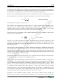
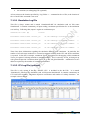
i TUFLOW AD USER MANUAL BUILD 2010-10-AD Contents TUFLOW AD User Manual GIS Based 2D/1D Advection Dispersion Modelling 2010 (Build 2010-10-AD) TUFLOW AD USER MANUAL BUILD 2010-10-AD i www.TUFLOW.com www.TUFLOW.com/forum [email protected] How to Use This Manual Chapters Table of Contents List of Figures List of Tables Appendices .tcf File Commands .adcf File Commands Glossary & Notation Contents i Contents Contents i About This Manual i About This Manual ii How to Use This Manual ii Chapters iii Table of Contents iv Appendices vi List of Figures vii List of Tables viii Glossary & Notation ix The image on the front cover is from an example multiple square harbour simulation that demonstrates the 2D and 1D simulation capabilities of TUFLOW AD TUFLOW AD USER MANUAL BUILD 2010-10-AD About This Manual ii About This Manual This is a user manual for the TUFLOW AD model, when it is called by TUFLOW.exe. TUFLOW AD relies on third party software to provide the interface between the user and the engine. These software packages are typically a text editor (e.g. UltraEdit), GIS platform (e.g. MapInfo), 3D surface modelling software (e.g. Vertical Mapper) and result viewing packages (e.g. SMS). Please refer to the user documentation or help of the third party software you have chosen to use in addition to this manual. This manual focuses predominantly on the TUFLOW AD model, and the user is referred to the TUFLOW and ESTRY manual for guidance on these hydrodynamic engines. It is assumed that the user is familiar with TUFLOW and has read the TUFLOW manual. How to Use This Manual This manual is designed for both hardcopy and digital usage. It was created using Microsoft Word 2003, and has not been tested in its digital mode in other platforms. Section, table and figure references are hyperlinked (hold down the Ctrl key and click on the Section, Table or Figure number in the text to move to the relevant page). Similarly, text file commands are hyperlinked and are easily accessed through the lists at the end of the manual (e.g. see .adcf File Commands). To quickly go to the end of the manual press Ctrl End. There are also command hyperlinks in the text (normally blue and underlined). Command text can be copied and pasted into the text files to ensure correct spelling. Some useful keys to navigate backwards and forwards are Alt Left / Right arrow to go backwards / forwards to the last locations. The Web Toolbar „Back‟ and „Forward‟ buttons can also be used to navigate. Ctrl Home returns to the front page. Any constructive suggestions are welcome (mailto:[email protected]). TUFLOW AD USER MANUAL BUILD 2010-10-AD Chapters iii Chapters 1 INTRODUCTION 1-1 2 OVERVIEW 2-1 3 THE MODELLING PROCESS 3-1 4 DATA INPUT 4-1 5 RUNNING TUFLOW 5-1 6 MODEL DEVELOPMENT 6-1 7 DATA OUTPUT 7-1 8 REFERENCES 8-1 TUFLOW AD USER MANUAL BUILD 2010-10-AD Table of Contents iv Table of Contents 1 2 INTRODUCTION 1.1 Overview 1-2 1.2 Solution Method 1-2 1.3 Constituent Transformation 1-4 1.4 Dispersion Formulation 1-4 1.5 Atmospheric Exchange Simulation 1-5 1.6 Planned Development 1-5 OVERVIEW Software Structure 2-2 2.2 Data Input 2-2 2.2.1 Structure 2-2 2.2.2 Suggested Folder Structure 2-3 2.2.3 File Types and Naming Conventions 2-4 2.2.4 GIS Input File Types and Naming Conventions 2-6 2.3 Performing Simulations 2-6 2.4 Data Output 2-6 2.4.1 Text files (Section 7.1.2) 2-6 2.4.2 Result Files (Section 7.2.1) 2-7 Limitations and Recommendations THE MODELLING PROCESS 2-7 3-1 3.1 Data Input Requirements 3-2 3.2 Calibration and Sensitivity 3-2 3.3 Model Resolution 3-2 3.3.1 3.4 4 2-1 2.1 2.5 3 1-1 2D Cell Size Computational Timestep DATA INPUT 3-2 3-3 4-1 4.1 Control Files – Rules and Notation 4-2 4.2 Simulation Control File 4-3 4.2.1 TUFLOW AD Control File (.adcf File) 4-3 4.2.2 Run Time and Output Controls 4-4 TUFLOW AD USER MANUAL BUILD 2010-10-AD Table of Contents v 4.3 GIS Layers 4-4 4.4 2D Geometries 4-5 4.4.1 5 6 7 4-5 4.5 1D Geometries 4-5 4.6 Specification of Constituent Properties 4-5 4.7 Boundary Conditions 4-8 4.7.1 Boundary Condition (BC) Database 4.7.2 BC Database Example 4-8 4-10 4.8 Initial Conditions 4-12 4.9 Minimum Dispersion Coefficient (Dw) 4-13 4.10 Meteorological Forcing Data 4-13 4.11 UltraEdit 4-13 RUNNING TUFLOW 5-1 5.1 Installing a Dongle 5-2 5.2 TUFLOW.exe and .dll Files 5-2 5.3 Using TUFLOW AD Via Third Party Software 5-2 MODEL DEVELOPMENT 6-1 6.1 Example Models 6-2 6.2 Setting up a New Model 6-2 DATA OUTPUT 7.1 7.2 7-1 General 7-2 7.1.1 Console (DOS) Window Display 7-2 7.1.2 TUFLOW AD Log Files 7-2 7.1.2.1 Simulation Log File 7-3 7.1.2.2 CFL Log File (optional) 7-3 7.1.2.3 Mass Log File (optional) 7-4 7.1.2.4 Iteration Log File (optional) 7-5 2D Domains 7.2.1 8 Multiple 2D Domains SMS (Map) Output (.dat or .xmdf Files) REFERENCES TUFLOW AD USER MANUAL BUILD 2010-10-AD 7-5 7-5 8-1 Appendices vi Appendices Appendix A A.1 Appendix B B.1 .tcf File Commands A-1 Control File Command (.tcf) A-2 .adcf File Commands B-1 AD Control File Commands (.adcf) B-2 TUFLOW AD USER MANUAL BUILD 2010-10-AD List of Figures vii List of Figures Figure 2-1 TUFLOW and TUFLOW AD Relationship and Data Input and Output Structure 2-3 TUFLOW AD USER MANUAL BUILD 2010-10-AD List of Tables viii List of Tables Table 2.1 Recommended Sub-Folder Structure 2-4 Table 2.2 List of Most Commonly Used File Types 2-5 Table 2.3 GIS Input Data Layers and Recommended Prefixes 2-6 Table 4.1 Reserved Characters – Text Files 4-2 Table 4.2 Notation Used in Command Documentation – Text Files 4-3 Table 4.3 TUFLOW AD Interpretation of MIF Objects 4-4 Table 4.4 Global Database Keyword Descriptions 4-5 Table 4.5 BC Database Keyword Descriptions 4-8 Table 4.6 2D Initial Conditions (2d_ad_ic) Attribute Descriptions 4-12 Table 4.7 2D Minimum Dispersion Coefficient (2d_ad_md) Attribute Descriptions 4-13 2D Metrological Spatial Coverage (2d_ad_met) Attribute Descriptions 4-13 Table 4.8 Table 7.1 _ADcfl.csv File Columns 7-4 Table 7.2 _ADmass.csv File Columns 7-5 TUFLOW AD USER MANUAL BUILD 2010-10-AD Glossary & Notation ix Glossary & Notation AD Advection dispersion. attribute Data attached to a GIS object. For example, a minimum dispersion coefficient is attached to a polygon using a column of Float type data. Build The TUFLOW Build number is in the format of year-month-xx where xx is two letters starting at AA then AB, AC, etc for each new build for that month. The Build number is written to the first line in the .elf and .tlf log files so that it is clear what version of the software was used to simulate the model. The first Build was 2009-01-AA. cell Square shaped computational element in a 2D domain. centroid The centroid of a region or polygon. CFL Courant–Friedrichs–Lewy condition. A stability criterion for explicit numerical schemes that sets the number of substeps TUFLOW AD executes within a single TUFLOW timestep. command Instruction in a file. constituent A water quality species to be simulated in TUFLOW AD. control file Text file containing a series of commands (instructions) that control how a simulation proceeds. The only control file in the AD module is the .adcf file. dispersion coefficient A coefficient applied to the diffusion terms of the conservation equation that increases or decreases the rate of spread of a constituent in response to ambient velocities and spatial gradients in constituent concentrations. It represents mixing that occurs in reality as a result of processes (e.g. sub-grid scale) that cannot be resolved in a numerical model. GIS Geographic Information System that can import/export files in MIF/MID format. grid The mesh of square cells that make up a TUFLOW model. layer A GIS data layer (referred to as a “table” in MapInfo). mif/mid MapInfo Industry standard GIS import/export format. SMS Surface Water Modelling Software distributed by Aquaveo (www.aquaveo.com) for viewing TUFLOW results. TUFLOW AD USER MANUAL BUILD 2010-10-AD 1-1 Introduction 1 Introduction Section Contents 1 INTRODUCTION 1-1 1.1 Overview 1-2 1.2 Solution Method 1-2 1.3 Constituent Transformation 1-4 1.4 Dispersion Formulation 1-4 1.5 Atmospheric Exchange Simulation 1-5 1.6 Planned Development 1-5 TUFLOW AD USER MANUAL BUILD 2010-10-AD 1-2 Introduction 1.1 Overview TUFLOW AD is an extension of the TUFLOW (and ESTRY) hydrodynamic engines. It is a computer program for simulating depth-averaged, two and one-dimensional constituent fate and transport. An example of such a constituent might include salinity. Both dissolved and particulate constituents can be simulated. TUFLOW AD takes depth and velocity fields computed by the TUFLOW and ESTRY engines and uses this information, together with initial and boundary conditions, to simulate the advection and dispersion of constituents. TUFLOW AD is specifically oriented towards such analyses in systems including coastal waters, estuaries, rivers, floodplains and urban areas. At present, it can handle 1D elements embedded into a single 2D domain within TUFLOW as SX connections. TUFLOW AD has been compiled to support all precisions and platforms used by TUFLOW, with a tailored dll for each, specifically: Windows 32 bit operating system single precision (TUFLOW_AD_iSP_w32.dll); Windows 32 bit operating system double precision (TUFLOW_AD_iDP_w32.dll); Windows 64 bit operating system single precision (TUFLOW_AD_iSP_w64.dll); Windows 64 bit operating system double precision (TUFLOW_AD_iDP_w64.dll); 1.2 Solution Method The TUFLOW AD 2D advection solution algorithm is based on the ULTIMATE QUICKEST method of Leonard (1991), Leonard & Niknafs (1991) and Leonard et al. (1993). It solves the full twodimensional, depth averaged, constituent conservation equation, including sink terms such as settling (for particulate species) and decay. The continuity equation is used to ensure conservation of mass, as described in Wu & Falconer (2000). The scheme also includes representation of mixing due to subgrid-scale turbulence and vertical shear via the dispersion formulation provided in Falconer et al. (2005). The 2-D representation of the conservation equation is provided by the following partial differential equation for an in-plan Cartesian coordinate frame of reference: (u ) (v ) = S + + Dx Dy t x y x x y y (2D Conservation) where = Dissolved constituent concentrat ion u and v = Depth averaged velocity components in X and Y directions x and y = Distance in X and Y directions t = Time D x , D y , D z = Turbulent diffusion coefficent s in the x, y and z directions S Source terms TUFLOW AD USER MANUAL BUILD 2010-10-AD 1-3 Introduction The terms of the conservation equation can be attributed to different physical phenomena. These are (in order from left to right) the rate of change of concentration in time, the transport of constituent due to the presence of concentration and velocity gradients (the advective terms) and turbulent diffusion due to irreversible mixing processes. The source terms (S) include settling and decay. Wu & Falconer (2000) demonstrated the need for an additional source term on the right hand side of the above equation to ensure mass conservation, this being Sa (with vertical velocities omitted): u Sa x v y (Mass Conservation) The meaning of the symbols is as per the above. The TUFLOW AD computational procedure used is an explicit scheme based on Leonard (1991). This contrasts to the TUFLOW engine, which employs an implicit scheme. As such, TUFLOW AD is generally subject to stricter stability constraints than the hydrodynamic engine. As such, the TUFLOW AD calculation takes the form of three steps within each timestep. The first step involves calculation of the Courant-Friedrichs-Lewy (CFL) condition at all wet cells, where the CFL in 1 dimension is: CFL u t x (CFL Condition) where u (or v) is fluid velocity and t and x are the timestep and grid scale, respectively. This condition is typically required to be less than 1.0 (additive for both X and Y directions) and has a broad physical interpretation requiring that the distance fluid is advected in one timestep (ut) is less than one grid cell (x). The second step is the computation of a similar condition for the diffusive lengthscale (related to the Peclet number) that ensures that dispersion also does not cause instability at any grid cell. The CFL and dispersion dimensionless numbers are then added and the maximum sum at any given location within a timestep is used to compute the number of sub-stepping iterations required by TUFLOW AD to remain stable within one TUFLOW timestep. The third step within each TUFLOW timestep is to execute the advection dispersion calculations for the required number of iterations, with a modified (smaller) t. The original ULTIMATE QUICKEST solution method has been enhanced and improved as applied in TUFLOW AD. For example, TUFLOW AD also employs adaptive computational stencil expansion where it identifies sharp constituent concentration gradients (Leonard & Niknafs, 1991). Where possible (i.e. away from boundaries and dry cells) and required, the ULTIMATE QUICKEST stencil is expanded from the standard third order scheme to a ninth order scheme, only on principle computational axes. Cross terms greater than third order are not included. If insufficient wet cells exist to switch to ninth order, then seventh and fifth order schemes are progressively tested (with commensurately decreasing stencils) until all required wet cells are located. Application of the ULTIMATE limiter (Leonard, 1991) has been found to induce steady flow anisotropy when extended to multi-dimensional problems and the numerical cross terms associated TUFLOW AD USER MANUAL BUILD 2010-10-AD 1-4 Introduction with additional dimensions are included in calculations. Wu & Falconer (2000) developed a modification to the ULTIMATE limiter that reduces this anisotropy, and this has been applied within the TUFLOW AD computational engine. 1.3 Constituent Transformation In addition to pure advection and dispersion, constituents simulated within TUFLOW AD are modified by transient boundary conditions, and optional settling and decay processes (with the latter being specifically developed to accommodate simulation of particulate material such as total nutrients). Boundary conditions can be set to vary in time for each constituent, and can be applied to all TUFLOW boundaries that set water levels and flows (either user-specified or computed), such as HT or QT. TUFLOW AD also supports SA inflow boundaries, where flows and concentrations are used to compute mass loads that are delivered to the model domain, mixed with ambient water and then resultant concentrations computed, prior to execution of the advection routines. Settling of constituents to simulate removal of particulate matter from the water column has been included in the engine as a simple linear process. Once settled, constituents do not re-enter the computational domain. TUFLOW AD also supports the decay of individual species (if positive decay rates are specified) and employs first order rate equations to do so. These equations draw on user defined decay rates. Up to twenty individual constituents can be simulated within TUFLOW AD. 1.4 Dispersion Formulation TUFLOW AD applies the dispersion formulation described by Falconer et al. (2005). This formulation computes dispersion in the X and Y directions (Dxx and Dyy respectively, to suit the Cartesian computational grid) from user specification of longitudinal and transverse dispersion coefficients Dl and Dt, respectively. Specifically, Dxx and Dyy are computed dynamically at each grid cell and timestep as follows: D D xx yy DlU 2 DtV 2 H g VC s 2 2 DlV DtU H TUFLOW AD USER MANUAL BUILD 2010-10-AD VC s +D w (X Direction Dispersion) +D w (Y Direction Dispersion) g 1-5 Introduction where D = User specified longitudinal dispersion coefficien t l D = User specified transverse dispersion coefficien t t U and V = Depth averaged velocity components in X and Y directions H = Water depth g = Gravitational accelerati on Vs = Velocity magnitude C Chezy coefficien t D User specified lower bound dispersion coefficien t w The value of Dw can be specified as constant or spatially variant as required. 1.5 Atmospheric Exchange Simulation As of release 2010-10-AD, full atmospheric exchange is simulated within TUFLOW AD. This exchange allows for active simulation of water temperature within TUFLOW AD, in response to open and inflow boundary forcing, and atmospheric interactions. The water temperature simulation framework adopted in TUFLOW AD requires specification of five (5) meteorological quantities: Incoming shortwave radiation (W/m2); Downwards longwave radiation (W/m2); Air temperature (oC); Relative humidity (0-1); and Wind speed (m/s). These can be specified at any timestep and linear interpolation is applied across all. TUFLOW AD also supports application of spatially variant meteorological forcing in these constituents across the 2D domain. This is achieved by the user specifying any number of regions across the domain, each of which has an association with a separate five-quantity meteorological data suite. 1.6 Planned Development The current version of TUFLOW AD (build 2010-10-AD) can be used to simulate constituent fate and transport in two- and (relatively simple) one-dimensional TUFLOW-ESTRY models. Future development items include (in no particular order): Full water quality simulation. frameworks; Explicit one dimensional simulation of constituents within HX connections. At present SX connections are supported via a simple mass transfer approach from structure entrance to exit. Embedded HX lines are not supported at present; TUFLOW AD USER MANUAL BUILD 2010-10-AD This item will most likely draw on existing tools and Introduction 1-6 Support for CN connections of 1D structures; Support for spatial variation of Dl and Dt; Simulation of constituent interactions (e.g. inter-related decay functions); Support for multiple 2D domains; Inclusion of restart file generation capabilities; and Execution of TUFLOW AD in isolation, without the need to compute hydraulics if they already exist. In general, these works are planned over 2011 and 2012, and will be included in upgrades and/or releases as appropriate. TUFLOW AD USER MANUAL BUILD 2010-10-AD 2-1 Overview 2 Overview Section Contents 2 OVERVIEW 2-1 2.1 Software Structure 2-2 2.2 Data Input 2-2 2.2.1 Structure 2-2 2.2.2 Suggested Folder Structure 2-3 2.2.3 File Types and Naming Conventions 2-4 2.2.4 GIS Input File Types and Naming Conventions 2-6 2.3 Performing Simulations 2-6 2.4 Data Output 2-6 2.5 2.4.1 Text files (Section 7.1.2) 2-6 2.4.2 Result Files (Section 7.2.1) 2-7 Limitations and Recommendations TUFLOW AD USER MANUAL BUILD 2010-10-AD 2-7 Overview 2.1 2-2 Software Structure TUFLOW AD is a computational engine that uses hydraulic information computed by TUFLOW on a timestep by timestep basis to simulate constituent fate and transport. Like TUFLOW, it does not have its own graphical user interface, but utilises GIS and other software for the creation, manipulation and viewing of data. These software platforms are: A GIS that can import/export .mif/.mid files (MapInfo Interchange Format files); 3D surface modelling software (e.g. Vertical Mapper) for importing 3D surfaces of model results into high quality reporting packages; SMS (Surfacewater Modelling System – www.aquaveo.com) or WaterRIDE (www.waterride.net) for the viewing of results and creation of animations; A text editor such as UltraEdit; and Spreadsheet software such as Microsoft Excel. 2.2 Data Input 2.2.1 Structure Figure 2-1 illustrates the data input and output structure, and the relationship between TUFLOW and TUFLOW AD. Text files are used for controlling TUFLOW AD simulations and simulation parameters. In general, the required inputs for TUFLOW AD are considerably simpler than for TUFLOW and this is primarily because all bathymetric, boundary condition location and 1D/2D network information is passed from TUFLOW to TUFLOW AD, avoiding the need for users to respecify this information within the AD module. The figure also demonstrates the relationship between TUFLOW and TUFLOW AD in that (at this time) TUFLOW AD is called by TUFLOW as a dynamically linked library (dll) at every complete timestep. TUFLOW AD USER MANUAL BUILD 2010-10-AD 2-3 Overview DTM GIS GIS Topography Boundary TimeSeries Data (Spreadsheet) Simulation Control (Text File) Input Data T U F L O W 2D Grid Location Boundary TimeSeries Data 1D & 2D Boundaries Simulation Control Map Data (SMS Formatted) Time-Series Data (Spreadsheet) Check Files (Stability & Mass Conservation) T U F L O W A D Optional Dispersion Data Map Data (SMS Formatted) High Quality Mapping High Quality Mapping Spatial Analyses Spatial Analyses (eg. Flood Damages) (eg. Median Contours) Output Data Figure 2-1 Input Data 2D/1D Links GIS Formatted Data Check Files (GIS & Text Files) (Text Files) Land Use (Materials) Map 1D Network Domains Optional Initial Conditions (Spreadsheet) Output Data TUFLOW and TUFLOW AD Relationship and Data Input and Output Structure 2.2.2 Suggested Folder Structure Table 2.1 presents the recommended set of sub-folders to be set up for a 2D/1D TUFLOW and TUFLOW AD model. It is an extension of that suggested in the TUFLOW manual. Any folder structure may be used, however, it is strongly recommended that a system similar to that below be adopted. For large modelling jobs with many scenarios and simulations, a more complex folder structure may be warranted, but should be based on that below. Note: Files are located relative to the file they are referred from. For example, the path and filename of a file referred to in AD Global Database is sourced relative to the AD Global Database, not the .adcf or .tcf file; Whilst TUFLOW AD accepts spaces in filenames and paths, other software may have issues with spaces. It is therefore recommended that spaces are not used in the simulation path and filename. Underscores are useful replacements; and Filenames and extensions are not case sensitive. TUFLOW AD USER MANUAL BUILD 2010-10-AD 2-4 Overview Table 2.1 Recommended Sub-Folder Structure Sub-Folder Description Locate folders below on the system network under a folder named “tuflow” in the project folder (e.g. J:\Project12345\tuflow). These folders should be backed up regularly bc_dbase Boundary condition database(s) and time-series data for TUFLOW (1D and 2D) and TUFLOW AD (2D) domains. model .tgc, .tbc, .tmf and other TUFLOW model data files, except for the GIS layers which are located in the model\mi folder (see below). No TUFLOW AD files are required here model\mi GIS layers that are inputs to the TUFLOW (2D and 1D) and TUFLOW AD (2D) model domains. Also GIS workspaces. These are only used for TUFLOW AD if spatially variable initial conditions and/or minimum dispersion coefficients are used. runs runs\log TUFLOW (.tcf or .ecf) and TUFLOW AD (.adcf) simulation control files. TUFLOW log files (.tlf or .elf and _messages.mif files) and TUFLOW AD log files (.adlf, _ADmass.csv and _ADcfl.csv) (use the TUFLOW Log Folder command) For large models the folders below can be located on a local hard drive under a folder “tuflow” under the project folder (e.g. C:\Project12345\tuflow) These folders do not need to be backed up regularly as the data they contain is reproducible results The result files (use the TUFLOW Output Folder command). check TUFLOW GIS and other check files to carry out quality control checks (use the TUFLOW Write Check Files command). Not used for TUFLOW AD at time of release. 2.2.3 File Types and Naming Conventions For TUFLOW AD, files are generally classified as: Control Files; Data Input Files (including databases); and Data Output Files. Control files are used for directing inputs to the simulation. The style of input is free form commands. Data input files are primarily comma-delimited files generated using spreadsheet software. If needed, GIS files can also be read as appropriate, although these are not required to execute TUFLOW AD. Data output files are primarily map output in SMS formats, text files and comma-delimited files (see Section 7). The most common TUFLOW AD file types and their extensions are listed in Table 2.2. TUFLOW AD USER MANUAL BUILD 2010-10-AD 2-5 Overview Table 2.2 List of Most Commonly Used File Types File Extension Description Format Control Files TUFLOW AD .adcf Simulation Control Called by the .tcf file (AD Control File). Controls the Text data input and output for an AD simulation. Mandatory. File Data Input Comma Delimited .csv Files These files are used for: Text Global data bases that capture constituent details; Boundary condition databases that itemise and cross reference boundary condition source tables; and Boundary condition source tables themselves. All are opened and saved using spreadsheet software such as Microsoft Excel. GIS MIF/MID Files .mif MapInfo‟s industry standard GIS data exchange format. .mid The .mif file contains the attribute data definitions and Text the geographic data of the objects. The .mid file contains the attribute data. Used for input of initial conditions or for specifying spatially variant dispersion characteristics. Optional, depending on level of sophistication within the AD model construction. The .mid files are of similar format to .csv files, so they can be opened by Excel or other spreadsheet software. Data Output (see Section 7) SMS Super File .sup SMS super file containing the various files and other (written by commands that make up the output from a single TUFLOW) simulation. Opening this file in SMS opens the Text TUFLOW .2dm file and the primary .dat files, including both TUFLOW and TUFLOW AD results. SMS Data File .dat SMS generic formatted simulation results file. TUFLOW AD output is written using the .dat format. TUFLOW AD USER MANUAL BUILD 2010-10-AD Binary 2-6 Overview 2.2.4 GIS Input File Types and Naming Conventions It is recommended that the prefixes described in Table 2.3 be adhered to for 2D GIS layers, where used. This greatly enhances the data management efficiency and, importantly, makes it much easier for another modeller or reviewer to quickly interpret the model. This approach is also consistent with that of TUFLOW. Table 2.3 GIS Input Data Layers and Recommended Prefixes GIS Data Type Suggested Description File Prefix Refer to Section 2D Domain GIS Layers 2D AD Initial Conditions 2d_ad_ic_ Layer containing polygon(s) defining the spatial 4.8 distribution of initial conditions for a given constituent. Optional. 2D AD Minimum 2d_ad_md_ Dispersion Coefficient Layer containing polygon(s) defining the spatial 4.9 distribution of minimum dispersion coefficients (D w) for a given constituent. Optional. 2D AD Meteorological 2d_ad_met_ Data Layer containing polygon(s) defining the spatial 4.10 distribution of applied five-quantity meteorological data sets. One polygon can be applied to the entire domain if required. Specification of this file in the AD Control File triggers water temperature simulation. Optional. 2.3 Performing Simulations TUFLOW AD simulations are started by running a TUFLOW simulation with the key command AD Control File. The presence or absence of this command determines whether TUFLOW calls the AD module or not, respectively. 2.4 Data Output TUFLOW AD produces a range of outputs as presented below. Output is structured into two categories: Text files for checking and quality control of models. Result files containing 2D results. 2.4.1 Text files (Section 7.1.2) These files are produced so that modellers and reviewers can readily check the model set up and integrity. The files take the following forms: TUFLOW AD USER MANUAL BUILD 2010-10-AD Overview A log file describing the model construction process and execution; A file listing all CFL data for each timestep; and A file listing total constituent masses at each timestep 2-7 2.4.2 Result Files (Section 7.2.1) Result files contain the computed spatial and temporal evolution of simulated constituents as SMS formatted files, both in .dat and .xmdf format as required. These files are binary. 2.5 Limitations and Recommendations TUFLOW AD is designed to model dissolved and particulate constituent advection and dispersion in coastal waters, estuaries, rivers, and floodplains. This is achieved through solution of the 2D transport equation using a variant of the ULTIMATE QUICKEST scheme first devised by Leonard (1991). Limitations to note include: 1 Simulation of constituents through 1D SX connections is currently only on a mass balance basis. That is, it is assumed that the concentration of a constituent exiting an SX connection is the same as that at the entrance to the connection at the same timestep. This approach conserves mass to the limit that these inflows and outflows are approximately equal and that the transit time through the SX connection is small compared to the timescale at which constituent concentrations vary at the upstream end of the SX connection. As such, only relatively „short‟ SX connections (using this timescale definition) should be simulated in the present release; 2 The dispersion scheme adopted by TUFLOW AD (Falconer et al. 2005) is such as to allow use of literature values for Dl and Dt. Users adopting literature values for these coefficients, however, should do so with extreme caution as they are known to vary widely, and by up to several orders of magnitude. It is always preferable to use monitoring data to calibrate advection dispersion models (TUFLOW AD included) and this should be done whenever and wherever possible. If no such data is available, then literature values can be used for Dl and Dt, however results need to be appropriately caveated, and TUFLOW AD predictions (as for any AD model) should be seen as qualitative or indicative at best. 3 Modelling predictions should also be cross checked with desktop calculations where possible. For example, this might include a hand calculation of expected salt masses in a given tidal system, with comparison made to TUFLOW AD text outputs. 4 TUFLOW AD allows for specification and computation of large dispersion coefficients, and with the automatic substepping implementation it should generally remain stable. However, specification of large (i.e. greater than approximately 100-500) dispersion coefficients may lead to results that are not physically real or defensible. As such, (in conjunction with 2 and 3 above) results should always be sanity checked and correlated with measurements. Relying on uncalibrated model predictions is not recommended. TUFLOW AD USER MANUAL BUILD 2010-10-AD 3-1 The Modelling Process 3 The Modelling Process Section Contents 3 THE MODELLING PROCESS 3-1 3.1 Data Input Requirements 3-2 3.2 Calibration and Sensitivity 3-2 3.3 Model Resolution 3-2 3.3.1 3.4 2D Cell Size Computational Timestep TUFLOW AD USER MANUAL BUILD 2010-10-AD 3-2 3-3 The Modelling Process 3.1 3-2 Data Input Requirements The minimum measured or literature data requirements for setting up a TUFLOW AD model are: 1 A properly constructed and stable TUFLOW hydraulic model (as detailed in Section 3.3 of the TUFLOW manual); 2 Boundary conditions for constituent concentrations (e.g. ocean salinities, catchment inflow pollutant concentrations, meteorological forcing etc.); Initial conditions, dispersion coefficients, settling and decay rates will all be set to zero if not specified to be otherwise. If no filename for a GIS layer specifying the distribution of meteorological data sets across the domain then water temperature will not be simulated. Preferable (and recommended) data requirements include: 1 Water quality calibration information as timeseries data at points. This is particularly important for dispersion coefficient calibration; 2 Spatially variant initial conditions; 3 Particulate matter settling rates (if any); 4 Dissolved species decay/transformation rates (if any); and 5 Spatially variant meteorological forcing data. 3.2 Calibration and Sensitivity Advection dispersion models are usually calibrated against water quality observations. For example, salinity recovery data can be used to calibrate and validate models, with longitudinal and transverse dispersion coefficients being the primary free variables. Dissolved and/or particulate constituents can then be simulated using the derived dispersion coefficients, and can include use of settling and/or decay rates as needed. Ideally, models should be calibrated for conditions similar to those under investigation (e.g. a catchment inflow to an estuary) although this is not always possible, particularly when data is limited. In these situations, sensitivity analyses could be carried out by increasing and decreasing calibration variables, but this not a preferred approach due to the large variability in the literature with respect to acceptable dispersion coefficients. 3.3 Model Resolution 3.3.1 2D Cell Size The cell sizes of 2D domains need to be sufficiently small to reproduce advection dispersion behaviour. It is worth noting that, in general, the larger the cell size is with respect to the scale of mixing processes, the greater potential there is for numerical dispersion to play a role in the model execution process. Even though TUFLOW AD has in-built measures to reduce these effects, it is TUFLOW AD USER MANUAL BUILD 2010-10-AD The Modelling Process 3-3 advisable to make sure that 2D cells are appropriately sized to minimise this effect, without seriously compromising simulation efficiency. 3.4 Computational Timestep The selection of the timestep is important for the success of a model in that the run time is directly proportional to the number of timesteps required to calculate model behaviour for the required time period. Notwithstanding this, TUFLOW AD automatically substeps with respect to TUFLOW on the basis of maintaining both advective and dispersive stability (see Section 1.2) so the selection of timestep should be focused on ensuring hydraulic stability, as AD stability should follow, providing reasonable dispersion coefficients are set. TUFLOW AD USER MANUAL BUILD 2010-10-AD 4-1 Data Input 4 Data Input Section Contents 4 DATA INPUT 4-1 4.1 Control Files – Rules and Notation 4-2 4.2 Simulation Control File 4-3 4.2.1 TUFLOW AD Control File (.adcf File) 4-3 4.2.2 Run Time and Output Controls 4-4 4.3 GIS Layers 4-4 4.4 2D Geometries 4-5 4.4.1 Multiple 2D Domains 4-5 4.5 1D Geometries 4-5 4.6 Specification of Constituent Properties 4-5 4.7 Boundary Conditions 4-8 4.7.1 Boundary Condition (BC) Database 4.7.2 BC Database Example 4-8 4-10 4.8 Initial Conditions 4-12 4.9 Minimum Dispersion Coefficient (Dw) 4-13 4.10 Meteorological Forcing Data 4-13 4.11 UltraEdit 4-13 TUFLOW AD USER MANUAL BUILD 2010-10-AD 4-2 Data Input 4.1 Control Files – Rules and Notation Like the TUFLOW control file (.tcf) the TUFLOW AD control file (.adcf extension) is a keyword driven text file. The commands are entered free form, based on the rules described below. Comments may be entered at any line or after a command. The commands are listed in the index in Appendix B. An example of a command is: AD GLOBAL DATABASE == ..\bc_dbase\2d_ad_globaldbase_run1.csv ! Simulation variables which sets the simulation global parameters and their properties. The text to the right of the “!” is treated as a comment and not used by TUFLOW AD when interpreting the line. The style of input is flexible bar a few rules. The rules are: A few characters are reserved for special purposes as described in Table 4.1 and Only one command can occur on a single line. Table 4.1 Reserved Characters – Text Files Reserved Character(s) Description “#” or “!” A “#” or “!” causes the rest of the line from that point on to be ignored. Useful for “commenting-out” unwanted commands, and for modelling documentation. == A “==” following a command indicates the start of the parameter(s) for the command. The notation used to document commands and valid parameter values are presented in Table 4.2. TUFLOW AD USER MANUAL BUILD 2010-10-AD 4-3 Data Input Table 4.2 Notation Used in Command Documentation – Text Files Documentation Notation Description < … > Greater than and less than symbols are used to indicate a variable parameter. For example, the commonly used <file> example is described below. <file> Is a filename (can include an absolute or relative path, or a URL/UNC path). Examples are: 2d_ad_ic_Run1.mif (must be co-located with global database file) ..\model\2d_ad_ic_Run1.mif (this is a relative path – the “..” indicates to move up a level) P:\jb99\tuflow\model\2d_ad_ic_Run1.mif (this is an absolute path) \\wbm\catchments\jb99\tuflow\model\2d_ad_ic_Run1.mif (this is a URL or UNC path) spaces Spaces can occur in commands and parameter options. If a space occurs in a command, it is only one (1) space, not two or more spaces in succession. Spaces can occur in file and path names. 4.2 Simulation Control File 4.2.1 TUFLOW AD Control File (.adcf File) The TUFLOW AD Control File or .adcf file points to the two mandatory files required for AD model execution. It is the top of the tree for the AD model and is called directly from TUFLOW via the .tcf (AD Control File command). The two files the .adcf file must reference are: one global database file using the AD Global Database command; and one boundary database file using the AD BC Database command. No other commands are required in the adcf file. In UltraEdit, the commands and comments can be colour coded for easier viewing (see Section 4.11). # This is an example of an .adcf file ! Comments are shown after a "!" or "#" character. ! Blank lines are ignored. Commands are not case sensitive. AD GLOBAL DATABASE == ..\bc_dbase\2d_ad_globaldatabase_Demo1.csv !global AD BC DATABASE == ..\bc_dbase\2d_ad_dbase_Demo1.csv !boundaries Appendix B lists and describes these commands and their parameters. TUFLOW AD USER MANUAL BUILD 2010-10-AD 4-4 Data Input 4.2.2 Run Time and Output Controls Both run time and output controls are set within the TUFLOW .tcf and the parameters specified there apply also to the AD simulation. Section 4.2.2 of the TUFOW manual describes these parameters. 4.3 GIS Layers GIS data layers are transferred into TUFLOW AD using the MapInfo data exchange MIF/MID format. This format is documented and in text (ASCII) form, making it easy to transfer GIS data. It is also available for import and export from most mainstream CAD/GIS platforms. As per TUFLOW, all GIS layers imported to TUFLOW AD must be in the same geographic projection. Only polygon data is read by TUFLOW AD, where this data specifies regions for initial conditions (Section 4.8) and/or minimum dispersion coefficients (Section 4.9) and/or the spatial distribution of meteorological data (Section 4.10). All are specified in the Global Database file (Section 4.6). GIS data is interpreted by TULFOW AD in the same manner as TUFLOW. Section 4.3 of the TUFLOW manual describes this interpretation. Table 4.3 repeats an abridged version, as applied to TUFLOW AD. Table 4.3 TUFLOW AD Interpretation of MIF Objects Object Type TUFLOW Interpretation Used Objects Region (polygon) Either effects any 2D cell or cell mid-side/corner (e.g. Zpt) that falls within the region. If the command is modifying a whole 2D cell, it uses the cell‟s centre to determine whether the cell falls inside or outside of the region. If the cell‟s centre, mid-side or corner lies exactly on the region perimeter, uncertain outcomes may occur. Holes within regions are accepted. Unused (Ignored) Objects Point Ignored. Line (straight line) Ignored. Pline Ignored. (line with one or more segments) Arc Ignored. Collections Ignored. Ellipse Ignored. Multiple (Combined) Objects Ignored. none Ignored. These most commonly occur when a line of attribute data is added that is not associated with an object. In MapInfo, this occurs when a line of data is added to a Browser Window. TUFLOW AD USER MANUAL BUILD 2010-10-AD 4-5 Data Input Roundrect (Rounded Rectangle) Ignored. Rect (Rectangle) Ignored. Text Ignored. 4.4 2D Geometries All 2D domain information is specified with TUFLOW (.tgc) and sent to TUFLOW AD as required. No additional geometry information is required or read by TUFLOW AD. 4.4.1 Multiple 2D Domains Multiple 2D domains are not currently supported by TUFLOW AD. 4.5 1D Geometries All 1D information (at current release only SX data) is read and processed by TUFLOW and ESTRY and required information passed to TUFLOW AD. TUFLOW AD does not require or read any further 1D data. TULFOW AD does not presently simulate HX, CN, 1D channels or embedded/linked 1D networks. 4.6 Specification of Constituent Properties Constituent properties are specified in the Global Database file, which is identified in the .adcf file using the AD Global Database command. This database file has a set structure, in much the same way as TUFLOW boundary database files, and can be created in software such as Microsoft Excel. The number of constituents simulated by TUFLOW AD is simply the number of non-commented line entries in this file (excepting the header data). Constituents can be removed from the simulation by prefacing rows in the global database file with the „!‟ or „#‟ character. The maximum number of constituents TUFLOW AD can simulate is 20. The global database file must be .csv (comma delimited) formatted. The first row must contain the predefined keywords (in order) as listed in Table 4.4, separated by commas. Subsequent rows contain constituent data. Table 4.4 Global Database Keyword Descriptions Keyword Name Description The name of a constituent. This might be „TN‟ or „Salinity‟ (without the inverted commas). The Name field is limited to 40 characters and must be alphanumeric characters only. Mandatory. Heat Name The path and name of the GIS .mif layer (2d_ad_met_) containing the polygon(s) describing the meteorological data spatial distribution across the model. This file must contain at least one polygon, and other objects are ignored. The existence of this file and path prompts TUFLOW AD to automatically simulate water TUFLOW AD USER MANUAL BUILD 2010-10-AD 4-6 Data Input Keyword Description temperature. If this path to a GIS .mif layer is specified, then the layer must comprise of polygons with a two attributes. The first attribute must be of type Character with a field size of 100. This field entry is the user defined name of the area covered by the polygon. It is used by TUFLOW AD to match the spatial coverage with csv records of the five (5) meteorological inputs data sets required to complete atmospheric heat exchange calculations. TUFLOW AD will check that all five records exist that match each polygon name, with the key in the input timeseries file being this attribute value concatenated with each of the five meteorological forcing data sets via a double underscore. Precise requirements are provided in Table 4.5. The second attribute for each polygon is of type Character with a field size of 3. This field is either blank or populated with an „S‟. If the latter is true then the timeseries associated with the polygon will be interpolated with a cubic spline. If the field is blank then linear interpolation is used. Linear interpolation is recommended. Decay Rate The decay rate (k) of the constituent in units of day-1. This value is used in a first order decay calculations at each timestep, i.e. C (t ) C0e kt where: C(t) is constituent concentration at time t C0 is a reference concentration k is the decay rate specified here; and t is time If no decay is required, then either enter 0 or leave the field blank. Settling Rate The settling rate of the constituent in units of m.day-1. This value is used in a simple mass balance calculation that removes the constituent from the water column based on this rate. If no settling is required, then either enter 0 or leave the field blank. Longitudinal The value Dl for the constituent, as per Section 1.4. Allowing such variation Dispersion between constituents permits simultaneous simulation of multiple constituents with Coefficient varying dispersion properties. This is useful at the model calibration stage when a range of dispersion coefficients can be tested within one simulation to ascertain the best match to monitoring data. This feature can also be used in sensitivity testing. Notwithstanding this, this value should not be varied from constituent to constituent once the AD model is calibrated. If the field is blank or set to zero, then longitudinal dispersion is switched off. Transverse The value Dt for the constituent, as per Section 1.4. Allowing such variation can be TUFLOW AD USER MANUAL BUILD 2010-10-AD 4-7 Data Input Keyword Description Dispersion exploited in the same manner as described above for longitudinal dispersion. This Coefficient value should not be varied from constituent to constituent once the AD model is calibrated. If the field is blank or set to zero, then transverse dispersion is switched off. Initial Condition This can be set to either a single number or a path reference to a GIS .mif layer (2d_ad_ic_). If the former is specified, then that value is applied uniformly to all wet cells at initialisation. If a path to a GIS .mif layer is specified, then the layer must comprise of (only) polygons with a single attribute. The attribute must be of type Float. The field name is not used by TUFLOW AD, so can be set to a label that is meaningful to the user. The polygon data, with spatially varying attributes of initial concentration is applied to wet cells at simulation initiation. Wet cells not covered by any polygon in the specified .mif layer are set to a concentration of zero. If the field is left blank, then a concentration of zero is applied to all cells. Minimum This is only used if the constituent being simulated is water temperature (as activated by specifying the location of the GIS mif layer of coverage polygons – see Heat Name description above). This field sets the minimum computed water temperature at each timestep. This is useful for avoiding unrealistic temperature predictions in very shallow waters. Maximum This is only used if the constituent being simulated is water temperature (as activated by specifying the location of the GIS mif layer of coverage polygons – see Heat Name description above). This field sets the maximum computed water temperature at each timestep. This is useful for avoiding unrealistic temperature predictions in very shallow waters. Minimum This sets the value of Dw as per Section 1.4. It can be set to either a single number Dispersion or a path reference to a GIS .mif layer. If the former is specified, then that value is applied uniformly to all wet cells at each timestep. If a path to a GIS .mif layer is specified, then the layer must comprise of (only) polygons with a single attribute. The attribute must be of type Float. The field name is not used by TUFLOW AD, so can be set to a label that is meaningful to the user. The polygon data, with spatially varying values of D w is applied to wet cells at each timestep. Wet cells not covered by any polygon in the specified .mif layer will have Dw set to zero. This field cannot be left blank. If a minimum dispersion of zero is required, then 0.0 must be entered in this field. End of file read errors will result if this field is left blank. An example global database file is provided in the demonstration models. TUFLOW AD USER MANUAL BUILD 2010-10-AD 4-8 Data Input 4.7 Boundary Conditions TUFLOW AD uses the same approach as TUFLOW to setting up boundary conditions in that two types of files are required: A boundary condition database; and Boundary condition data files (i.e. timeseries). Like TUFLOW, TUFLOW AD also uses comma delimited format for both these file types. TUFLOW AD does not require specification of any geographical information regarding the location of non-meteorological boundary conditions. All such required data is passed from TUFLOW to TUFLOW AD for TUFLOW boundary types HT, QT, HS, HQ, QC, VC, VT, and SA. SX data is passed as needed. 4.7.1 Boundary Condition (BC) Database A boundary condition (BC) database is set up using spreadsheet software such as Microsoft Excel. It must be .csv (comma delimited) formatted and is identified in the .adcf file (see AD BC Database). The database contains a list of files and attribute names to search for within those files. The attribute names are then used to extract the desired boundary condition data. The AD BC database is structured in the same way as a TUFLOW BC database in that it must contain a header line with subsequent rows of information. The header line must contain the keywords Name, Source, Column 1, Column 2, Add Col 1, Mult Col 2, Add Col 2, Column 3, Column 4 in that order, with meanings as per Table 4.5. Table 4.5 BC Database Keyword Descriptions Keyword Name Description The name of a BC data set. It consists of two concatenated elements as follows: First: This must be the same „Name‟ attribute used in any of the following GIS input files if they are specified: o the GIS 2d_bc layer(s) specified in TUFLOW. This is third attribute in the 2d_bc layer and follows „Type‟ and „Flags‟. It may contain spaces, but must not contain commas. It is not case sensitive; and/or o the GIS 2d_sa_ layer(s) specified in TUFLOW. This is only attribute in the 2d_sa layer. It may contain spaces, but must not contain commas. It is not case sensitive; and/or o the GIS 2d_ad_met_ layer specified in TUFLOW AD. This is first attribute in the 2d_ad_met_ layer. See Table 4.8. It may contain spaces, but must not contain commas. It is not case sensitive. TUFLOW AD USER MANUAL BUILD 2010-10-AD 4-9 Data Input Keyword Description Second: This must be the name of the appropriate constituent for which the boundary condition is being specified (either constituent concentration or meteorological data). o If a constituent concentration boundary is specified (to match a 2d_bc_ or 2d_sa_ „Name‟ field specification), then this second concatenated element must be the same name as one of those constituents specified in the AD Global Database „Name‟ field. o If a meteorological forcing data set is specified (to match a 2d_ad_met_ polygon „Name‟ field specification), then this second concatenated element must be one of the five (5) mandatory meteorological data sets required to drive the water temperature and atmospheric exchange calculations. These are pre-specified unique names as follows: o AT; RH; WS; SW; and LW. These correspond to (respectively): Air temperature (C); Relative humidity (0 to 1); Wind speed (m/s); Short wave radiation (incoming, W/m2); and Longwave radiation (downwards, W/m2). These two elements are joined by a double underscore, regardless of whether the names have been sourced from 2d_bc_, 2d_sa_ or 2d_ad_met_ inputs. For example, if only 2d_bc_ boundaries are specified and “M” 2d_bc boundary condition objects specified in TUFLOW, and “N” constituents to be simulated by TUFLOW AD, then M*N entries are required in the AD BC Database. An example is Ocean__Salinity, where the TUFLOW 2d_bc file has a polyline with Name attribute “Ocean” and the AD Global Database has a variable called “Salinity” listed. Alternatively, if Only water temperature was simulated, and there were “M” 2d_bc_ boundary condition objects specified in TUFLOW; and “P” 2d_ad_met_ polygons specified across the domain, there would be M*1 + P*5 entries required in the AD BC Database. If one of the meteorological boundary polygons was named “East”, then there would be five row entries with the value in this field being East__AT, East__RH, East__WS, East__SW and East__LW.. TUFLOW AD USER MANUAL BUILD 2010-10-AD 4-10 Data Input Keyword Description Mandatory (water temperature simulation is optional). Source The file from which to extract the BC data. It must be a .csv file. Paths are relative to the AD Global Database. Mandatory. Column 1 The name of the first column of data (time values) in the .csv Source File. Mandatory. Column 2 The name of the column of data in the .csv Source File. Values in this column are concentrations or temperatures, depending on the BC set applied. These are applied to cells corresponding to the appropriate locations of all types of BCs specified in TUFLOW 2d_bc GIS layers. These specified concentrations/temperatures override any other computed concentrations/temperatures at the boundary locations. Contrasting to the above are SA boundaries, where the specified concentration/temperature in the timeseries data is multiplied by the inflow corresponding to that concentration/temperature (as passed to TUFLOW AD from TUFLOW) and the mass/heat load over the SA polygon computed. This mass/heat load is then added to the mass/heat of constituent within the wet computational cells within the SA polygon, and mass/heat conservation used to compute a new resultant ambient concentration/temperature. The exception to the above specification of concentrations or temperatures (whether they be used to override computed values at boundaries or multiplied by flows in the case of SA polygon simulation) is in the case of meteorological forcing. In that case, the five (5) meteorological data sets have the units specified above in the Name row of this table. Mandatory. Add Col 1 Not used. Leave Blank. Mult Col 2 Not used. Leave Blank. Add Col 2 Not used. Leave Blank. Column 3 Not used. Leave Blank. Column 4 Not used. Leave Blank. 4.7.2 BC Database Example The Excel spreadsheet below illustrates a simple example of an AD BC database set up in a worksheet that is exported as a .csv file for use by TUFLOW AD. Two polyline 2d_bc_boundaries have been specified via GIS in TUFLOW (with Name fields “North” and “South”) and two constituents have been specified in the AD Global Database (with Name fields “Tracer_01” and “Temperature”). One polygon 2d_sa_ inflow boundary has been specified via GIS in TUFLOW (with Name field “Central”), and two meteorological polygons have been specified via GIS in TUFLOW AD as a 2d_ad_met_ file (with Name fields “Upper” and “Lower”). Two 2d_bc_ boundaries, one 2d_sa TUFLOW AD USER MANUAL BUILD 2010-10-AD Data Input 4-11 boundary and the simulation of two constituents including water temperature across two meteorological zones thus requires 2*2 + 1*2 + 2*5 = 16 entries in the BC database file. The Demo2_WT.csv file was created by saving the below as a .csv file from Excel. All values are temperatures (C), with the exception of the Time column, which has units of hours. The Demo2_SA.csv file was created by saving the below as a .csv file from Excel. Values in the C_T column are temperatures (C), and values in the C_Tr1 column are concentrations. The Time column has units of hours. The Demo2_met.csv file was created by saving the below as a .csv file from Excel. All values are in units specified in Table 4.5 (Name row), with the exception of the Time column, which has units of hours. TUFLOW AD USER MANUAL BUILD 2010-10-AD 4-12 Data Input The Demo2_Conc.csv file was created by saving the below as a .csv file from Excel. All values are in concentrations, with the exception of the Time column, which has units of hours. 4.8 Initial Conditions Initial conditions are specified for each constituent as either a constant value or spatially variant (see Table 4.4). The former is simply entered as a decimal (or integer) in the Initial Condition field of the AD Global Database. This value is applied to all wet cells at model initiation. The latter is applied by entering a relative (or absolute) file path to a GIS layer in the Initial Condition field of the AD Global Database. The GIS file has the attributes described in Table 4.6. Table 4.6 2D Initial Conditions (2d_ad_ic) Attribute Descriptions GIS Attribute Conc Description Type The initial condition concentration. Float As many polygons as needed can be included in this layer. Any wet cells not covered by these polygons will be initialised to a concentration (or water temperature) of zero. The naming convention prefix for this layer is 2d_ad_ic_. The objects must be polygons – rectangles, round rectangles etc. are not read by TUFLOW AD. The attribute name is not read by TUFLOW AD and can be anything meaningful to the user - “Conc” is used as an example above for clarity. “WaterTemp” could equally be used. TUFLOW AD USER MANUAL BUILD 2010-10-AD 4-13 Data Input 4.9 Minimum Dispersion Coefficient (Dw) Minimum dispersion coefficients are specified for each constituent as either a constant value or spatially variant (see Table 4.4). The former is simply entered as a decimal (or integer) in the Minimum Dispersion field of the AD Global Database. This value is applied to all wet cells at all timesteps. The latter is applied by entering a relative (or absolute) file path to a GIS layer in the Minimum Dispersion field of the AD Global Database. The GIS file has the attributes described in Table 4.7. Table 4.7 2D Minimum Dispersion Coefficient (2d_ad_md) Attribute Descriptions GIS Attribute MD Description Type Minimum dispersion coefficient. Float As many polygons as needed can be included in this layer. Any wet cells not covered by these polygons will be assigned a minimum dispersion coefficient of zero. The naming convention prefix for this layer is 2d_ad_md_. The objects must be polygons – rectangles, round rectangles etc. are not read by TUFLOW AD. The attribute name is not read by TUFLOW AD and can be anything meaningful to the user - “MD” is used as an example above for clarity. 4.10 Meteorological Forcing Data Meteorological data can be specified as spatially variant across the model domain. This is achieved by specifying a GIS mif layer containing at least one polygon. If no spatial variation is required then one polygon can be used to cover the entire domain, or if multiple spatially distinct meteorological data sets are available then each can be assigned to a polygon in the mif layer. The GIS file has the attributes described in Table 4.8. Table 4.8 2D Metrological Spatial Coverage (2d_ad_met) Attribute Descriptions GIS Attribute Name Description The name of the area covered by the meteorological polygon. Type Character (100) Flag A flag to designate use or otherwise of spline interpolation. Either „S‟ or blank. Blank forces TUFLOW AD to use linear temporal interpolation of input Character (3) meteorological data. Use of ‘S’ is not recommended. As many polygons as needed can be included in this layer. Any wet cells not covered by these polygons will not be assigned any meteorological data and atmospheric exchange will not be simulated for unassigned cells. It is the user‟s responsibility to ensure that all cells are covered appropriately. The naming convention prefix for this layer is 2d_ad_met_. The objects must be polygons – rectangles, round rectangles etc. are not read by TUFLOW AD. 4.11 UltraEdit UltraEdit (www.ultraedit.com) is recommended as the text editor for TUFLOW text files. UltraEdit has many excellent features, of which a few are noted here. TUFLOW AD USER MANUAL BUILD 2010-10-AD Data Input 1 4-14 A file “Wordfile.txt” is provided with TUFLOW in the UltraEdit folder. Replace the equivalent file in the UltraEdit installation folder (typically “C:\Program Files\UltraEdit”) with the one provided with TUFLOW. UltraEdit will now colour code TUFLOW, ESTRY and TUFLOW AD text files. (Note: If you have modified the UltraEdit Wordfile.txt file for your own purposes, you will have to merge the two files.) You can change the colours in UltraEdit via Advanced, Configuration, Syntax Highlighting menus. For more recent versions of UltraEdit, you may have to rename the “Wordfile.txt” provided to „tuflow.uew‟ and include it in the wordfiles directory that has other .uew files (such as „vbscript.uew‟). This directory may be something like C:\Program Files\IDM Computer Solutions\UltraEdit\wordfiles You will then need to delete all content from the „tuflow.uew‟ file except that relating to TUFLOW and ESTRY. This information starts at the line: “/L14"TUFLOW and ESTRY" Line Comment = “… You will also need to change the number after the leading L to be the number of files in the directory containing your .euw files (including the tuflow.uew file). The example above has thirteen other .euw files read by UltraEdit in the wordfiles directory, so the tuflow.euw file leading line was changed to start with /L14. On startup, UltraEdit reads all 14 files, and then offers the associated colour coding options in a drop down menu in Advanced > Configuration > Editor Display > Syntax Highlighting as per the below 2 UltraEdit has a very useful feature that allows opening of a file that is specified in the active text file. Place the pointer anywhere over the text of the file you wish to open and click the right mouse button. The top menu item on the pop-up menu will open the file. TUFLOW AD USER MANUAL BUILD 2010-10-AD 5-1 Running TUFLOW 5 Running TUFLOW Section Contents 5 RUNNING TUFLOW 5-1 5.1 Installing a Dongle 5-2 5.2 TUFLOW.exe and .dll Files 5-2 5.3 Using TUFLOW AD Via Third Party Software 5-2 TUFLOW AD USER MANUAL BUILD 2010-10-AD Running TUFLOW 5.1 5-2 Installing a Dongle Dongle installation instructions and operating rules are provided in the TUFLOW manual, and do not differ for TUFLOW AD. 5.2 TUFLOW.exe and .dll Files As of Build 2008-08-AA, TUFLOW executable code consists of five TUFLOW .exe/.dll files, and several system .dll files. The files are: TUFLOW.exe TUFLOW_LINK.dll TUFLOW_USER_DEFINED.dll TUFLOW_AD.dll TUFLOW_MORPHOLOGY.dll Several system .dll files. These are supplied as they may not exist on your computer – do not delete or relocate these .dlls – keep them with the TUFLOW. exe/.dll files. The TUFLOW_AD.dll file is the AD module. It is only called if the AD Control File command is present in the TUFLOW .tcf file, and the appropriate dongle is activated for the AD module. All .exe and .dll files must be placed in the same folder and kept together at all times. When replacing with a new build, archive the files by creating a folder of the same name as the Build ID (e.g. 2008-08AA), and place all files in this folder. 5.3 Using TUFLOW AD Via Third Party Software Construction of TUFLOW AD driver files is not yet supported through SMS or any other third party platforms. Works are underway to offer SMS capabilities. However, if the .tcf, .adcf and associated AD .csv files are present and properly constructed within the TUFLOW structure, then executing TUFLOW via third party interfaces will trigger execution of the AD module automatically (with an appropriately configured dongle). These files do not need a graphical user interface to generate, and can be constructed manually relatively easily. This is primarily because TUFLOW AD does not require provision of spatial information over and above that provided to it by TUFLOW. The only exception to this is if (optional) spatial information is required by TUFLOW AD (Sections 4.8 and 4.9). If this is the case then these will need to be generated in a GIS and included in the AD Global Database constituent descriptions. TUFLOW AD USER MANUAL BUILD 2010-10-AD 6-1 Model Development 6 Model Development Section Contents 6 MODEL DEVELOPMENT 6-1 6.1 Example Models 6-2 6.2 Setting up a New Model 6-2 TUFLOW AD USER MANUAL BUILD 2010-10-AD Model Development 6.1 6-2 Example Models Two example models are distributed with the TUFLOW AD release. The first model is designed to demonstrate the key features of TUFLOW AD and uses a hypothetical four-„harbour‟ domain to do so. This harbour domain is based loosely on that published by Wu & Falconer (2000). The second example is reflective of more real world conditions. A TUFLOW AD licence is required to execute these models. 6.2 Setting up a New Model The steps below describe the process for setting up a TUFLOW AD model. It is assumed that the user is familiar with TUFLOW and that the folder structure for TUFLOW has been setup with all required files. The user should run the TUFLOW model without the AD module first to make sure that it is appropriately configured and stable. Create a TUFLOW AD control file (.adcf) 1 Use a text editor to create an empty .adcf file and save it to the “runs” folder. Set up AD global database (.csv file) 2 Set up TUFLOW AD global database in the “bc dbase” folder (see Table 4.4). 3 In the .adcf file use AD Global Database to set the location of the global database as follows. AD Global Database == ..\bc dbase\my ad global dbase.csv Setup up the boundary condition tables (.csv file(s)) 4 Setup the boundary condition table(s) in the “bc dbase” folder (Section 4.7.2). Setup up the boundary condition database (.csv file) 5 Setup the boundary condition database in the “bc dbase” folder (Section 4.7.1) that references the tables set up in the previous step. 6 In the .adcf file use AD BC Database to set the location of the bc database as follows. AD BC Database == ..\bc dbase\my ad bc dbase.csv Setup up TUFLOW to activate the AD module (.tcf file) 7 In the .tcf file use the command AD Control File to set the location of the adcf and activate execution of the AD module as follows. AD Control File == ad_run.adcf Run the model 8 Run TUFLOW as normal. The AD module will be called and results files written as described in Section 7. TUFLOW AD USER MANUAL BUILD 2010-10-AD 7 Data Output Section Contents 7 DATA OUTPUT 7.1 7.2 7-1 General 7-2 7.1.1 Console (DOS) Window Display 7-2 7.1.2 TUFLOW AD Log Files 7-2 7.1.2.1 Simulation Log File 7-3 7.1.2.2 CFL Log File (optional) 7-3 7.1.2.3 Mass Log File (optional) 7-4 7.1.2.4 Iteration Log File (optional) 7-5 2D Domains 7.2.1 SMS (Map) Output (.dat or .xmdf Files) TUFLOW AD USER MANUAL BUILD 2010-10-AD 7-5 7-5 7.1 General 7.1.1 Console (DOS) Window Display TUFLOW AD displays a lot of information to the Console (DOS) Window during the data input stages. If there are data input problems, trace back through the Window buffer (no buffer is available on Windows 98) to establish where in the input data process the problem occurs. Alternatively, search the .adlf file. Once the simulation has started, the TUFLOW simulation status at each timestep is displayed. TUFLOW AD module writes to screen only when results files are written to disk as an additional line to the TUFLOW output as (for a constituent called „Tracer_X‟): Finished computing AD field for constituent: Tracer_X The Console Window appears as something similar to that shown below, where Temperature and Salinity have been simulated in the TUFLOW AD module. The colours, size and other attributes of the window can be changed as required. 7.1.2 TUFLOW AD Log Files TUFLOW AD text (i.e. not results) outputs are written to two log files in the location specified by „Output Folder‟ in the .tcf file (or the “runs” folder if this command is not used): A simulation log file; A CFL condition log file (optional); A mass balance log file (optional); and TUFLOW AD USER MANUAL BUILD 2010-10-AD An iterations (or substepping) file (optional). All are written to the location specified by „Log Folder == „ command in the .tcf file, or the location of the .tcf itself if this command is not used. 7.1.2.1 Simulation Log File This file is always written and is named „SimulationX.adlf‟ for simulation (and .tcf file) name SimulationX. It contains commentary of input reading, constituent specification etc. as the simulation sets itself up. Following that, output is regular at each timestep as: Simulation time (h) 0.0125 Finished constituent Tracer_01 at AD substep iteration number 1 Finished constituent Tracer_02 at AD substep iteration number 1 Finished constituent Tracer_02 at AD substep iteration number 2 Finished constituent Tracer_02 at AD substep iteration number 3 These lines show information regarding the simulation time for each constituent. In particular, the number of AD sub-steps needed to be executed to maintain stability under CFL and Peclet conditions is reported. In the above example, constituent Tracer_01 required no substepping, whilst constituent Tracer_02 required 3 substep iterations to maintain stability. This is caused by Tracer_02 being set up with greater dispersion coefficients than Tracer_01 in the AD global database. Additional rows are added as required by the number of constituents simulated. 7.1.2.2 CFL Log File (optional) This file is only written if the flag “WRITE CFL” is included in the adcf file. It is named „SimulationX_ADcfl.csv‟ for simulation (and .tcf file) name SimulationX. It contains commentary on CFL and Peclet numbers, maximum dispersion coefficients and number of substep iterations. An example is shown below. TUFLOW AD USER MANUAL BUILD 2010-10-AD Specifically, the column data is as per Table 7.1: Table 7.1 _ADcfl.csv File Columns Column time (h) Constituent Name Max_CFL_u Description The simulation time in hours. The name of the constituent as specified in the AD global database. The maximum CFL for u velocities anywhere in the computational domain at that timestep. Max_CFL_v The maximum CFL for v velocities anywhere in the computational domain at that timestep. Max_Peclet_u The maximum Peclet number for u dispersion anywhere in the computational domain at that timestep. Max_Peclet_v The maximum Peclet number for v dispersion anywhere in the computational domain at that timestep. Max_sum_u The maximum of the sum of CFL and Peclet numbers in the x (u) direction anywhere in the computational domain. Max_sum_v The maximum of the sum of CFL and Peclet numbers in the y (v) direction anywhere in the computational domain. Max_Disp_x The maximum dispersion coefficient in the x (u) direction anywhere in the computational domain. Max_Disp_y The maximum dispersion coefficient in the y (v) direction anywhere in the computational domain. Num_iterations The number of iterations required by TUFLOW AD to remain stable. This can vary from constituent to constituent if different dispersion coefficients are applied. 7.1.2.3 Mass Log File (optional) This file is only written if the flag “WRITE MASS” is included in the adcf file. It is named „SimulationX_ADmass.csv‟ for simulation (and .tcf file) name SimulationX. It contains commentary on mass conservation. An example is shown below. TUFLOW AD USER MANUAL BUILD 2010-10-AD Specifically, the column data is as per Table 7.2: Table 7.2 _ADmass.csv File Columns Column time (h) Constituent Name 1 Description The simulation time in hours. The total mass of that constituent in the computational domain. TUFLOW AD assumes that the constituent concentrations are specified in mg/L, and this number is then in tonnes of constituent. If the concentration is g/L, then this number should be multiplied by 1000 to be in units of tonnes. Constituent Name 2 As per constituent 1. Column repeated until all constituents have been accounted for 7.1.2.4 Iteration Log File (optional) This information is only written if the flag “WRITE ITERATIONS” is included in the adcf file. Information is written as additional data to the adlf (see Section 7.1.2.1) if this flag exists. If so, the following is written to the adlf at each timestep, for constituent Y at substep iteration Z: Finished constituent Y at AD substep iteration number Z 7.2 2D Domains 7.2.1 SMS (Map) Output (.dat or .xmdf Files) TUFLOW AD produces one of two (or both) output formats, and these are set in the tcf file by using the Map Output Format command. These are: SMS formatted (*.dat) output files. The .ALL.sup (SMS) file created by TUFLOW is altered by the AD module to load the .dat AD results files automatically. One .dat file is produced for each constituent listed in the AD global database, in that order. These can also be loaded directly into SMS using the .2dm file produced by TUFLOW as a geometry. An example of the data sets loaded by the .ALL.sup structure in SMS is shown below. XMDF formatted output file. This file format offers a range of advantageous features: TUFLOW AD USER MANUAL BUILD 2010-10-AD o All map output is in the one file (ie. all .dat files become one .xmdf file and this .xmdf file is the same as that produced by TUFLOW – i.e. all TUFLOW and AD data sets are written to the same file). o Much faster to access and instant load up when first opened due to an indexing system located in the file header. o Data are stored in a folder structure that software such as SMS can use to access the data. Specifically, the AD data sets within the TUFLOW .xmdf file are all included within a folder named “AD”. See image below as an example. o Data stored as either static or temporal (time) based. o Format is an industry standard and recognised by other software. Executable code available to write applications that access the data. Two existing TUFLOW tools are relevant to the post-processing of .dat files (if required). The TUFLOW utility TUFLOW_to_GIS can be used to convert these files to GIS files (*.asc) as per standard TUFLOW files. For example, the following command will create an ASCII grid at 5m resolution at time = 10 hrs from the file Demo2_TSS.dat TUFLOW_to_GIS.exe –asc –grid5 –k10 Demo2_TSS.dat Similarly, dat_to_dat.exe can be used to create a dat file at one timestep only, e.g. dat_to_dat.exe–k10 Demo2_TSS.dat The main reason not to use .xmdf files at this stage is these utility programs are not yet updated to work with .xmdf files. To output in the .xmdf format use Map Output Format == XMDF in the tcf. TUFLOW AD will automatically follow suit in output file format. TUFLOW AD USER MANUAL BUILD 2010-10-AD 8 References Falconer, R.A., Lin, B. and Kashefipour, S.M. (2005) Modelling Water Quality Processes in Estuaries Computational Fluid Dynamics: Applications in Environmental Hydraulics, Eds P.B. Bates, S.N. Lane and R.I. Furguson. John Wiley and Sons. Leonard, B.P. (1991) The ULTIMATE Conservative Difference Scheme Applied to Unsteady OneDimensional Advection Computer Methods in Applied Mechanics and Engineering 88:17-74. Leonard, B.P. and Niknafs, H.S. (1991) Cost-Effective Accurate Coarse-Grid Method for Highly Convective Multidimensional Unsterady Flows NASA Centre for Aerospace Information Report 91N21075. Leonard, B.P., MacVean, M.K. and Lock, A.P. (1993) Positivity-Preserving Numerical Schemes for Multidimensional Advection NASA Centre for Aerospace Information Report 93N27091. Wu, Y. and Falconer, R.A. (2000) A Mass Conservative 3-D Numerical Model for Predicting Solute Fluxes in Estuarine Waters Advances in Water Resources 23:531-543. TUFLOW AD USER MANUAL BUILD 2010-10-AD .tcf File Commands Appendix A .tcf File Commands AD Control File TUFLOW AD USER MANUAL BUILD 2010-10-AD A-1 .tcf File Commands A.1 A-2 Control File Command (.tcf) AD Control File == <.adcf_file> AD Control File == <.adcf_file> (Mandatory to trigger AD module) Triggers TUFLOW to execute AD simulation and specifies the TUFLOW AD control file name. Example: AD Control File == Demo1.adcf TUFLOW AD USER MANUAL BUILD 2010-10-AD A-2 .adcf File Commands Appendix B .adcf File Commands AD Global Database AD BC Database WRITE CFL WRITE MASS WRITE ITERATIONS TUFLOW AD USER MANUAL BUILD 2010-10-AD B-1 .adcf File Commands B.1 B-2 AD Control File Commands (.adcf) AD Global Database == <file> B-2 AD BC Database == <file> B-2 WRITE CFL B-2 WRITE MASS B-2 WRITE ITERATIONS B-2 AD Global Database == <file> Mandatory A pointer to a file containing constituent information (e.g. name and dispersion coefficients) – see Section 4.6. AD BC Database == <file> Mandatory A pointer to a file containing boundary database information (e.g. names of boundary files as mapped to GIS data sets read by TUFLOW) – see Section 4.7.2. WRITE CFL Optional A command to generate a cfl commentary output file. Useful for tracking potential instabilities. WRITE MASS Optional A command to generate a mass conservation commentary output file. WRITE ITERATIONS Optional A command to add further numerical iteration data to the ad log file output. TUFLOW AD USER MANUAL BUILD 2010-10-AD