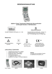
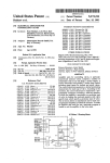
1
BioStim
Battery-supplied Floating End-stage
&
Battery Manager
User's Manual
SUPERTECH
Important notes
The battery pack is very sensitive! It will be destroyed on irreversible way, if the Endstage has been forgotten in Power ON position, and the battery pack is overdischarged, even in one time. You should take special care of this aspect.
The battery pack can not be overcharged, because the Battery Manager has got an
automatic charger, and conditioner circuitry. The Charging of Battery function of the
Battery Manager can be activated even for prolonged periods.
For the sake of the battery pack the Power ON switch should be turned on for the
necessary time periods only. But there is a very important aspect to keep in mind
always. The Power ON switch should be turned on before connecting the output
wires to the biological object! It is also necessary to disconnect the output of the Endstage from the biological object before turning the Power switch off! The reason, why
it is important is the following: this equipment is not a simple stimulus isolator unit,
but an isolated End-stage. It means, that the floating electronic sections (the
Constant Current, and the Constant Voltage Generators) are isolated from the other
circuits via 4 kV isolation security, and very small isolation capacity optocouplers, but
the isolated, floating sections are quite difficult electronic circuits. These circuits are
powered from 120 V supply voltage. During the switching on period (in a few
milliseconds of time window) these circuits are “standing up”. Similarly, in the
switching off period the voltages of these circuits are “demolished”. These circuits
are designed to work perfectly in normal operating conditions, but the switching on,
and switching off transients are not normal working periods. In these short time
intervals huge voltage transients (approximately 100 V in amplitude) voltage spikes
are appeared at the output connectors. These spikes make catastrophic electrical
shocks for the biological object.
The parts of the BioStim universal biological stimulator system
The BioStim system is divided into two functional parts. The time parameters are
generated by the fully digital BioStim Controller, and the analogue voltage and current
sources are implemented in the End-stages. The parts of the system are
manufactured as independent equipments. On one hand it results a more flexible and
variable system, because the similar parts (e.g. the End-stages) are compatible, and
they can be changed easily. On the other hand the divided system meets the special
experimental requirements much better, because the analogue End-stages can be
located close to the biological objects in the shielded environment, but the digital
BioStim Controller, can be placed anywhere else. BioStim Computer Interface is an
alternate of the BioStim Controller in special cases. You can find detailed descriptions
about each elements of the BioStim system in the appropriate manuals.
Battery-supplied Floating End-stage
It can be used for the most sophisticated, noise-sensitive microelectrode experiments
(for example multi-electrode, and patch clamp environments). It passes extremely
small, practically zero hum noise into the biological tissue. There is a Constant
Current Generator, and a Constant Voltage Generator built into this End-stage. The
output of the End-stage can be switched between Constant Current, and Constant
Voltage modes on-the-fly, during the experiment. It is a very useful feature, because
the first stimulating trials can be carried out in the secure Constant Voltage mode. If
the experiment is qualitatively working, the End-stage can be switched into Constant
Current mode, where the electric charge can be defined exactly. The only limitation
is, that the alternation from the Constant Current Generator to the Constant Voltage
Generator, or vice versa, must not be done during an active output pulse, only in the
pauses between the pulses. If you would do this action even so, than an unwanted
voltage, or current transient would be appeared at the output connectors (because
the momentary voltage, and current levels of the two generators are different in the
duration of the pulses, and they would be equalized through the biological object
connected to the output connectors). The Constant Voltage mode has got two
ranges: 10 V, and 100 V of full scale. The Constant Current mode has got two
ranges: 100 µA, and 10 mA of full scale. The output amplitude in the selected range
can be set using a 10-turn calibrated helical potmeter on the front panel. The
nonlinearity (total amplitude error) of the End-stage is less than 5%. This End-stage is
supplied from its built-in rechargeable battery pack. This model has got an additional
accessory, the Battery Manager unit, which is an automatic, and precision battery
charger, and conditioner equipment. The nominal voltage of the internal battery pack
is 120 V, and its nominal capacity is 170 mAh. With a new battery pack the average
operation time (the efficient working period between two charging actions) is
approximately 12 hours. If you take care of the battery pack, its lifetime will be two
years at least, if the End-stage is used every day, the battery pack is charged if
necessary, but the battery is never over-discharged. The Battery-supplied Floating
End-stage is optimized for that aspect, that it does not generate any electric noise,
because of its battery-powered scheme. According to this feature it can be placed
close to the experimental object anywhere, even in a seriously shielded environment.
Front panel controls
The middle switch at the top section is the selector of the working mode of the Endstage. It can be used to switch between the Constant Current, and Constant Voltage
modes. This switch can be alternated anytime during the pauses.
Left to the working mode switch there is the range selector of the Constant Current
Generator. The Constant Current mode has got two ranges: 100 µA, and 10 mA of
full scale. This switch is ignored, if the Constant Voltage mode is selected by the
working mode (middle) switch.
Right to the working mode switch there is the range selector of the Constant Voltage
Generator. The Constant Voltage mode has got two ranges: 10 V, and 100 V of full
scale. This switch is ignored, if the Constant Current mode is selected by the working
mode (middle) switch.
Most left at the bottom section there are the output connectors. These two
connectors are the floating output connectors of the End-stage. They are compatible
with the 4 mm banana jacks. Furthermore they have got isolated plastic screws to fix
simple wires up to 1 mm in diameter. Be careful! The output connectors are high
voltage connectors! They are especially dangerous to touch in the Constant Current
mode, because the compliance voltage (120 V) can be present here!
Next to the output connectors there is the output Polarity selector switch. The output
connectors are identical except their polarity. There are many experimental
arrangements, where the polarity of the stimuli has no importance. But if the polarity
is important, it can be changed easily with this switch. This switch can be alternated
anytime during the experiment.
In the middle at the bottom section there is the Control indicator LED. This is a dim,
red LED. It is used to indicate visually the presence of the digital pulses at the input
of the End-stage.
Next to the Control LED there is the Pulse Amplitude potmeter. The amplitude of the
output pulses (always in the selected range) can be set using this 10-turn calibrated
helical potmeter. If the scale of this potmeter shows 10.00 than the full scale value
of the actually selected range is passed to the output connectors. If the scale of this
potmeter shows 0.00 than zero value is passed to the output connectors.
Most right at the bottom section there is the Power ON switch. Never forget it in
switched on position for prolonged periods, because the internal battery pack will be
destroyed on irreversible way if you over-discharge it. There is no “power-on”
indicator LED on the Battery-supplied Floating End-stage, because the current
consumption of a LED is as high as the current requirement of the complete Endstage. By eliminating the LED the operation time (the efficient working period
between two charging actions) of the End-stage was increased efficiently. The Power
ON switch should be turned on before connecting the output wires to the biological
object. It is also necessary to disconnect the output of the End-stage from the
biological object before turning the Power switch off (see the Important notes
section, too).
The connectors at the back side
At the left side there is a 3-pole, high voltage connector. It is used to connect the
End-stage to the Battery Manager with a high-voltage cable. You should always use
the special cable provided by Supertech. Never touch the pins in the plugs of this
interconnecting cable, because high voltage is present at both of the ends of this
cable! The only safe position, if this cable is connected to both of the equipments.
Avoid to use other battery charger equipments than the Battery Manager, because
the internal battery pack has got special requirements to meet.
In the middle there is the Internal Floating Shield connector. It is compatible with the
4 mm banana jacks. Furthermore it has got an isolated plastic screw to fix a simple
wire up to 1 mm in diameter. Since the Battery-supplied Floating End-stage is
designed to work in a seriously shielded environment, it is essential to shield the
internal circuitry rigorously. The Internal Floating Shield connector is used for this
purpose. You should connect it to the common Ground point of the Faraday-cage.
The best point where it should be connected exactly can be found during the pilot
experiments, when the lab is set up at first time.
Above the Internal Floating Shield connector there is a switch, what can be used to
disconnect the Battery-supplied Floating End-stage from the Battery Manager. Usually
the Battery Manager does not generate hum noise, if its mains switch is turned off,
but under special circumstances (e.g. with extremely high impedance electrodes, or
with very high gain set in the amplifier) you can find hum noise in the Faraday-cage.
In such situations you can disconnect the End-stage, and the Battery Manager
completely (galvanically) with this switch.
At the right side there is the Isolated Control connector. It is used to connect the Endstage to the BioStim Controller, or to the BioStim Computer Interface. You should
always use the special cable provided by Supertech. Avoid to use other controllers
directly, except the BioStim Controller, or the BioStim Computer Interface. Any
external pattern generator equipment, or any output port bit of a data acquisition card
of a PC should be connected through the BioStim Controller, or through the BioStim
Computer Interface, on standard TTL levels, at their appropriate connectors.
Battery Manager
It is very important to keep in mind to take care of the battery pack always. The
battery pack is very sensitive. It can not be overcharged, because of the
sophisticated Battery Manager equipment. The only danger for the battery pack is, if
the End-stage is forgotten in switched on position for a prolonged period, and the
battery pack is over-discharged below the nominal lowest voltage. This action
destroys the battery pack. To reach the longest lifetime of the battery pack, it is the
best way to charge it fully, and discharge it fully, but not below the lowest voltage
level, what can be indicated by the Battery OK LED.
During active, stimulator usage of the Battery-supplied Floating End-stage (if its
Power switch is ON) the green mains switch of the Battery Manager should be
switched off, because its line frequency transformer generates a rude noise in the
shielded environment. The Battery Manager has been designed to support Charging of
Battery, and Checking of Battery operating modes. Its mains switch should be turned
on only in these two operating modes.
The Charging Current LED at the front of the Battery Manager is a visual indicator. Its
brightness is proportional to the actual charging current. It is always lighting a little
bit (in Charging of Battery function), even when the battery pack is charged
completely, because a small current is always provided for the battery pack against
its self-discharge.
The Battery OK LED at the front of the Battery Manager is an indicator driven by an
internal comparator circuitry. If you push the Battery Test button (in Checking of
Battery function), a dummy load of 20 mA is connected to the battery pack. This load
is higher, than the total current consumption of the End-stage. During the application
of this huge load current, the comparator checks the voltage of the battery pack. If
its voltage is higher, than the nominal lowest voltage, than the Battery OK LED is lit.
There is a drawing of interconnections of the Battery-supplied Floating End-stage, and
the Battery Manager in the Appendix.
There is a summary of the operating modes of the Battery-supplied Floating Endstage, and the Battery Manager in the Appendix.
Further development
Until now we have developed many different features for the Battery-supplied
Floating End-stage, as it is listed above. In spite of this, if you can not find the
appropriate function for your special task in our actual choice, and this function
seems to be interesting for other our customers, we will develop this function
especially for you. It is our method, how we improve the features of our equipment.
We collect all the notices and feedbacks of our customers, and we implement their
(may be your) knowledge into the features of BioStim.
Warranty
We give you full warranty service, including rest parts for the period of 3 years by
default. Longer warranty periods can also be defined and agreed (the actual
conditions should be discussed before placing the order).
The warranty is valid only in that case, if the End-stage is controlled by the BioStim
Controller, or by the BioStim Computer Interface.
The Battery-supplied Floating End-stage is supported with full warranty, except the
internal battery pack. Since the lifetime of the battery pack is a subject of the care of
the user, Supertech can not provide warranty for the battery pack.
International technical hotline by phone: (36) (20) 9234-386
Technical hotline by email: [email protected]
Mains
OPTIONALLY:
115V to 230V
AC Transformer
High voltage
Battery Manager
BioStim Controller, or
Pulse Output
Stimuli
BioStim
Computer Interface
BioStim
Battery-supplied
Floating End-stage
Biological
object
Interconnections of the Battery-supplied Floating End-stage,
and the Battery Manager
IMPORTANT! The Power ON switch should be turned on before connecting
the output wires to the biological object. It is also necessary to disconnect
the output of the End-stage from the biological object before turning the
Power switch off (see the Important notes section, too).
The most important operating mode selector is the Power ON switch of the Batterysupplied Floating End-stage. If it is in Power ON position, the End-stage is working. In this
situation (during stimulting actions) the battery pack can be accessed by the Battery
Manager, but the mains transformer of the Battery Manager is working, so a hum noise
may be generated. Even in Power OFF position of the End-stage, the Battery Manager can
access the battery pack, if the appropriate switch at the back side of the End-stage
allows it. The battery handling functions can be selected by the Check/Charger function
switch, and the mains switch of the Battery Manager. During Checking of Battery, and
Charging of Battery operating modes the mains switch of the Battery Manager should be
switched on. According to the actual positions of these switches, the following
operating modes can be selected:
Operating
Mode
Switch
positions
Switched OFF
End-stage Power OFF
Bat.Man. Mains OFF
Bat.Man. Charger
This is that mode, when the equipment is completely
switched off. If you do not want to use it, select this
mode to take care of the battery pack.
Operation
End-stage Power ON
(optionally: select
completely floating by
the back side switch)
Bat.Man. Mains OFF
This is the stimulating operation mode of the Endstage. In this mode the End-stage is working,
supplied by the battery pack. Never forget the
equipment in this mode, if you do not use it! If you
operate the equipment in this mode, it is sometimes
necessary to switch to Checking of Battery mode to
test the actual condition of the battery pack. The
position of the Check/Charger switch is not
important during Operation.
Charging
of Battery
End-stage Power OFF
Bat.Man. Mains ON
Bat.Man. Charger
If the battery pack is chargeable (it is not faulty), the
Charging Current LED indicator is shining. The
intensity of the LED's light is proportional to the
charging current. If the battery pack reaches the fully
charged state, the Charging Current LED is fading
away.
Checking
of Battery
End-stage Power OFF
Bat.Man. Mains ON
Bat.Man. Check
In this mode the battery test circuit is switched on. If
you push the Battery Test button, it switches a
strong load current (about 20 mA) to the battery
pack. The battery test circuit checks the battery pack
under this extra load. If the battery pack is in good
condition, the Battery OK LED is shining. If you can
not see a light from Battery OK LED in this situation,
please, stop any other activity, and select Charging
of Battery mode, because the battery pack is in
dangerous condition!
Description
Operating modes of the Battery-supplied Floating End-stage,
and the Battery Manager