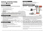
1
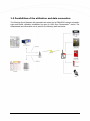
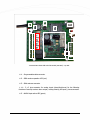
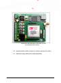
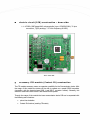
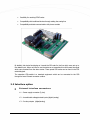
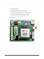
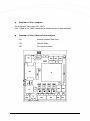
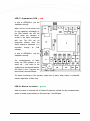
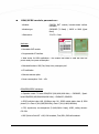
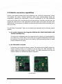
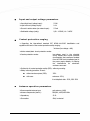
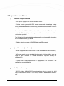
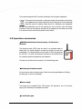
M2M Easy Communicator ® Technical specification _____________________________________ Rev: 1.1.6 2012-03-21 Document specification This document was made by the WM Rendszerház Kft. for the M2M Easy Communicator® device. This Technical Specification contains the description how to understanding of the structure and working theory of the device, furthermore the description of the installation and configuration steps are also included. Document category: Technical specification Product: M2M Easy Communicator Made by: Tóth Csaba, WM Rendszerház Kft. Contact: Email: [email protected] Validated by: Papp Zsolt Document version: REV 1.1.6 Pages: 33 Hardware version: REV 2.1 Bootloader version: REV 0v89 Firmware version: Document status: REV 1v592 Class: Public Made at: 2010. October 13. Last changes: 2012. March 21. Date of authorization: 2012. March 21. Final 2 Table of Contents 1. INTRODUCTION ........................................................................................... 5 1.1 Product Overview .................................................................................................................. 5 1.2 Application areas .................................................................................................................. 6 1.3 Possibilities of the utilization and data connection ................................................................... 6 1.4 Main features ...................................................................................................................... 7 2. DEVICE CONSTRUCTION .............................................................................. 11 2.1 Internal construction .......................................................................................................... 11 2.2 Interface connectors .......................................................................................................... 16 2.3 LED functionality ................................................................................................................. 19 2.4 Main components ............................................................................................................... 21 2.5 Module connection facilities ................................................................................................. 25 2.6 Technical specification and data .......................................................................................... 25 2.7 Operation conditions .......................................................................................................... 28 2.8 Optional accessories ........................................................................................................... 30 3. PARAMETER OPTIONS .................................................................................. 31 4. SUPPORT .................................................................................................... 32 5. LEGAL NOTICE ............................................................................................. 33 Chapter 1: Introduction Thank You for choosing the M2M Easy Communicator® device for your work. 1.1 Product overview The M2M Easy Communicator® is a reliable GSM/GPRS data transmitter device in compact size. The primary function of the device is the maintenance of the remote digital inputs and the setting of the remote digital outputs (logical). The data communication works through the cellular network. Furthermore, there is a special expansion panel to tune up the device able to forward the Contact ID signals of an alarm system or an alarm center towards to a remote monitoring center - with DTMF codes. Through the usage of the device it's supersede to use traditional analog phone line for signal transmission. When the analog phone line is already possessed this device can be a backup channel in case of GPRS network problems - its more secure to send the signals through separated lines. The M2M Easy Communicator® is properly suitable to connect with IP receiver to forward the information towards the dispatcher service provider. Through the widely supported functions and the reliable working of GSM/GPRS standards the device is highly applicable for assuring the communication background of monitoring systems on that way, that every type of sensors and various communication modules can be connected. The communicator is eligible for sending SMS messages as replies for the signal changes of the inputs or initiate a voice call or sending a pre-defined data package through the GPRS network. The outputs of the device can be controlled by SMS text messages. 4 The device is applicable for transmitting the alarm signals of alarm centers in CID format. The configuration is possible through SMS messages or with a PC. The communicator device passes the required data through the GPRS network to the remote monitoring center or the M2M server in Contact ID format. 1.2 Application areas TheM2M Easy Communicator® offers a complete solution to target areas where it's required to use a device which is easily configurable, cose-effective, and uses intelligent GSM/GPRS communication. The device through it's widely applicable properties can be offered for the following various areas: To collect the provided data from home safety security devices and transmitting them to the alarm center Where alert and monitoring tasks are required Elevator monitoring, maintenance tasks Elderly monitoring tasks Maintenance of digital outputs (SMS, Voice, GPRS) Remote controlling (SMS, Voice, GPRS) Transmitting the measurement data from metering devices (for ex. Water meter) through the device inputs General measurement- and data receiving and collection tasks - through the input interfaces Fire protection tasks (fire-, smoke signal transmission) Gate opening functions (remotely, call-based) Forwarding the data of further measurement instruments and the events of alarm devices through connecting further sensors (sending alerts, alarm codes, data) 5 1.3 Possibilities of the utilization and data connection The following figure illustrates with examples that which kind of GSM/GPRS network connection types and further utilization possibilities are open for M2M Easy Communicator® device. The collected data and information can be used for the following tasks and areas. 6 1.4 Main features Hardware functional characteristics : GPRS transmitter device electrical circuit option (optional: can be ordered with aluminium case) Outstanding capacity and high power RISC-based, ATMEL AVR® microcontroller (7.37 MHz, 8 MIPS) - for the operation system and for running the the stored programs from the microchip Widely supported memory areas: 32 kbyte flash program storage area 1 kbyte EEPROM memory for data storage 2 kbyte internal SRAM memory Supporting the independent provider solution and SIM-card usage - operation and full functionality from foreign country cellular network service provider area Support of cellular network data transmission standards GSM/GPRS data transfer Forwarding data, event and information through cellular network (measurement data, security events, industrial sensors' data or other provided signal or events) Operation status LEDs Dedicated RTC (Real Time Clock) chip for handling the real time Power Management function (wakes up the processor in defined intervals when a pre-defined event occurs) – in case of low-power supply design Integrated temperature sensor (inside the module) 7 Watchdog function Reduced power consumption (low energy consumption) Modular construction (base board (electric circuit) + Contact ID expansion module + other accessory modules) with board-to-board standard connection/switch mounting possibility: - CID module (phone line emulation, Contact ID functions, DTMF decoder – in case of analog line integration or when compatibility needs are required) Further arbitrary accessory modules can be choose: MBus (RS485, RS422) - industrial interface module Easy Battery - accumulator module I/O Expander - input/output expansion module Short RF (868MHz, ZigBee) module Assured high availability, reliable quality built-in components (ATMEL® AVR® processor, SIMCOM® module, etc.) Analog phone line connection option Configuration deletion possibility 4 digital inputs (for sensors) 2 digital outputs (for relays and alarm) Antenna connection facility Software characteristics : Reliable and fast, special system software (firmware) which were specially designed and developed for industrial application areas The software was implemented in several projects as a technical solution in production - wide-range of requirements were accomplished Network-support services and access of data protocols (TCP, UDP) 8 Handling of fixed or provider-given dynamical IP addresses Access and availability of remote monitoring and maintenance communication protocols (data transferring (TCP, UDP) in security, safety areas , Enigma, WM-Alarm protocols) Signal transmission for remote monitoring tasks Sending life signals Configurable internal Contact ID codes Standard industrial communication and programmable interfaces Serial port connection possibility: RJ11 (for applications, industrial usage and self developed programs) Network recovery function in case of connection failure - rebuilds the connection when cellular network hangs or cuts the device off or in case of network access problems Check and monitoring of network connection (continuously checks the availability of the cellular network) M2M server integration capability for redirection of data to a central place to collect and store them in safety - for further evaluation, etc. (storage in central database, visualization in web interface, graphic visual options, event management, remote access possibility, etc.) Management options on the WM-M2M® web interface Configuration definition file upload to the device (from PC) and configuration download options (from the device) 9 Software and parameter upload options : Confuiguration, Program upload • with Terminal utility (firmware upload through serial port (RJ11 conn.)) Software for loading the Parameter file • with DR-TERM application (Configuration file upload, parameter configuration (RS232 conn.)) Configuration options: Locally • through serial port • with DR-TERM application Remotely (with SMS text messages) • Yes 10 Chapter 2. Device construction The communicator device contains a high-performance RISC-based ATMEL processor to serve the available functions, which runs the required programs for the proper functioning of the device. The device was designed for receiving signals from various sensors or serve data from a external data collector device or make connection with a data center system - it's all possible through its' digital inputs and outputs. 2.1 Internal construction electric circuit (PCB) construction – top side: 1 – power supply connector (2-pins, Microfit standard connector) 2 – power supply presence LED (green) 3 – red/yellow operation LED (for the various program statuses) 4 – 4x digital inputs with two-way switch – for voltage or contact input selection (IN1..IN4), technically required for connecting sensors 5 – input operation LEDs (voltage/contact) - 4x, green 6 – 2x digital (logical/analog) output sor relay outputs (OUT1, OUT2) 7 – 2x digital relay output status LED (yellow) 8 – battery supply connector (optional with an extension module) 9 – SIM-holder 10 – CID-module mounted on the standard interface connector 11 N y Á 13 2 K 8 1 2 ( 15 C 11 9 3 12 I 13 D 16 f 4 5 4 e 10 l 14 é p í t 6 12 7 é 15 s s C Communicator device PCB with CID-module (mounted) – top side 11 – Programmable cable connector 12 – GSM modem operation LED (red) 13 – SMA antenna connector 14 – 3 x 2 pins connector for analog inputs (alarm/line/phone) for the following functions of security centers: alarm output / analog entering line input / phone connector 15 - ALARM input active LED (green) 12 17 16 Communicator device PCB without a CID-module – top side (the GSM/GPRS module is visible) 16 – standard interface modular connector (for example receiving a CID-module) 17 – GSM/GPRS module (SIMCOM SIM 300DZ/340DZ/900D) 13 electric circuit (PCB) construction – down side: 1 – ATMEL® RISC-based AVR® microcontroller (type: ATMEGA324PA, 32 pins connection, TQFP package, 7.37 MHz frequency/8 MIPS) 1 PCB – down side accessory CID-module (Contact ID) construction The CID module accessory means an expansion possibility for the Communicator device. With the usage of this module the device will be able to operate as a special GPRS transmitter (connection with the board-to-board B2B_1 and B2B_2 connector surface). Generally, this module is used when alarm center is also wired into the system. Through the usage of the module the base communicator device PSB can be expanded with the following extra functions: phone line simulation Contact ID functions (sending CID-codes) 14 Possibility for receiving DTMF codes Compatibility with traditional devices through setting the analog line Compatibility and data communication with phone centrals By default, this device functioning as it sends the CID-code for the line which were set up to the related input. When we’d like to use the device as a transmitter this will forward the signal which were received from the alarm center. These special CID codes can be found in the CID code table/pad. The extension CID-module is a standard equipment which can be connected to the PCB through its board-2-board connector surface. 2.2 Interface option External interface connectors : 1 – Power supply connector (2-pins) 2 – 4x switchable voltage/contact inputs (digital /analog) 3 – 2x relay outputs (digital/analog) 15 4 - SMA antenna connector 5 – Simulated phone-line connector (Phone signal) 6 – Incoming analog phone-line connector (Line signal - RJ11) 7 – Outgoing analog phone-line connector (Alarm signal) 8 – SIM holder 1 8 5 4 2 2 5 6 3 7 3 16 Kommuni 3 Communication capabilities: GSM standard data transmission Voice transmission GSM SMS Voice Wireless data transmission GPRS Internal interface connector line • Yes • Yes • Yes • Yes (SIMCOMM SIM300/340DZ/900D module) Debug • Yes Contact ID (CID) module MBus, RS485, RS422 (Industrial interface extension module) I/O Expander (IO expander module) ShortRF module (868 MHz, Zigbee) • Yes • Yes • Yes • Yes Review of the inputs The Communicator device has 4 inputs. Every of them can be separately configurable to operate as a voltage or contact input. This setup can be achieved with the input-switch(es) which is behind the input connector line(s) – SW1; SW2; SW3; SW4. The figure below shows that the two-way switch is in down/low-position (towards the LEDs), the input behave as a contact input. In the other case (up/top-position) this operates as a voltage input. In voltage-mode the input can be activated with 5-24V DC (digital, 1), in the other case its inactive (digital, 0). These inputs and its’ working mode can be also configured from the device software. 17 Review of the outputs The device has 2 relay output (CS11, CS12). 0,5A - 125VAC or 1A - 24VDC voltage can be switched through on these interfaces. Review of the internal connectors CS2: Antenna connector (SMA conn.) CS3: SIM-card holder CS6: RJ11 phone connector 18 CS7-CS8: IN1-IN4 inputs (voltage or contact) CS9-CS10: Standard surface connector for mounting expansion modules (like the Contact ID module) CS11-CS12: Outputs (for relay/switch), for example sabotage defence tasks CS13 : Power supply connector /GND +12V/ CS14, CS15, CS16: Alarm, Line and Phone connectors 2.3 LED funcionality Operation LEDs and statuses LED 1: GSM/GPRS status Device status LED status Symbol blinks quickly the device registered to the GSM network blinks slowly communication/call is active lights out the device is not yet registered to the GSM network or its’ registration is on the way (in process) ● LED 2-5: Inputs - green There are four LEDs for the four inputs with a green light. When the input is active (at the contact input the two poles are closed short; the voltage at the input > 5V DC) the current input has a LED which lights out. LED 6: Operation – yellow During GPRS connection this LED blinks. When the GPRS connection was successful, the LED lights continuously. The LED during the GPRS communication switch into blinking. 19 LED 7: Operation LED – red in case of LEDFIELD=0 (see the Installation manual): When you turn on the device until it’s not registering successfully on the GSM network this LED will blinks. When the operation is normal it will lights continuously with red. The LED can be temporarily blinking when the device receives a parameter or a command through an SMS message. in case of LEDFIELD=1 (see the Installation manual): The number/amount of blinks shows the GSM gradient in the actual cell – this refers to the gradient level, the intervals between the blinks is circa 3 seconds, the interval time is around 200msec. The device functioning in this operation mode when it starts. When there’s no successful network registration, it blinks once. LED 8: Alarm is active - green When the device is mounted with a Contact ID expansion module and the connected alarm system is actually communicating on the alarm input - the LED lights. 20 LED 9-10: Outputs - yellow There are two yellow LEDs for all the two outputs (each one has one attaching LED). When the output is active, the relay closes short the associated clip. The LED for the output will operate (lights out). LED 11: Power supply - green Indicates that the circuit is under power supply or not. When it lights the PCB is under 12V power supply. 2.4 Main components Microcontroller parameters: Technology: ATMEL megaAVR-based microcontroller (MCU) with RISC technology Type: ATmega324P, low-power and low consumption Interface type: 32-pins in TQFP package Frequency: 7.37 MHz (8 MIPS) Address: 8 bit Processor (CPU) attributes: 32 kbyte flash program storage memory area, 1 kbyte EEPROM, 2 kbyte internal SRAM Consumption: 2.7-5.5V, normal: 0.4mA, stand-by: 0.6µA, power down/off: 0.1µA Memory attribute(s) : External memory : 512 kbit EEPROM (optional) 21 GSM/GPRS modul e parameters: Module: SIMCOM SMT module, board-to-board surface connector Module type: SIM300DZ (Tri Band) / 340DZ or 900D (Quad Band) Dimensions: 33 x 33 x 3 mm Attributes: Mountable SMT module Programmable AT interface Ideal choice for M2M applications – the modem was made in small size with low power needs, low power consumption Extended functions: SMS, Fax, Data, Voice, emergency call CE certification External antenna option Power consumption: 3.4V – 4.5V GSM/GPRS/EGPRS attributes: Operation mode: Tri-band GSM/GPRS (900/1800/1900 MHz) – SIM300DZ / Quadband GSM/GPRS (850/900/1800/1900 MHz) – SIM340DZ / SIM900D GPRS multi-slot class 10/8 (85.6kbps max. DL), GPRS mobile station class B, GSM phase 2/2+: Class 4 (2W @ 850/900 MHz), Class 1 (1W @ 1800/1900MHz) CSD, asynchrone, non-transparent (2.4/4.8/9.6/14.4 kbps), USSD, coding schema: CS1-CS4 SMS (Point-to-Point MT + MO, Cell broadcast, Text /PDU, SMS cell broadcast 22 Fax (Group 3 Class 1) Data: PBCCH support Software attributes: Programming: SIMCom AT-commands, GSM 07.07 and 07.05. SIM Appl. TCP/IP stack, PPP-stack Audio (Codecs: Half rate (HR), Full rate (FR), Enhanced Full rate (EFR), Hands-free operation (Echo suppression)) Interfaces: status Audio: 2 x analog External antenna mounting option (50Ω) RTC backup serial/debug connection GPIO SIM 3V, 1.8V 23 2.5 Module connection capabilities There’re a few optional modules which can be attached to the M2M Easy Communicator® device. This operation also needs a software elaboration (which means program/software upload and configuration) regarding the requirements it could be implemented by the WM Rendszerház You’ve only one thing to do, to choose the way how (and what for) You’d like to use the device and describe that which sensors or other equipments You’d like to attach to the system. Our team at the WMR will help You and support Your decision to choose the ideal module and the to find best way to reach your needs. The M2M Easy Communicator® device can be attached and associated with the following optional modules: a.) no module connected (the integrated SIMCOM SIM 300DZ/340DZ/900D GSM module is available only) This option can be interesting when the analog phone line support is not recommended for your needs (for ex. DTMF codes). In this mode only the general mobile/cellular functions will be functioning. The device can work in this mode as a GSM gate-opening system (a special firmware needed for this mode). b.) the CID-module connected In this mode You’ll be able to forward or receive CID codes through the GRPS network to a remote monitoring service, or it’s possible to use the device as a GSM transmitter. The module supports the analog line backup function. The WMR recommends and offer this module to attach it as a standard and default configuration. The CID module 24 Accessory module detailed functions: Simulated analog line generating – through the device can communicate with an analog equipment/device through the GSM network Analog phone line connection possibility (it can be configured that the GSM line or the analog line will be the primary line) Analog phone line output for further equipments/devices For transmitting/forwarding the Contact ID signals of an alarm center/system through the analog phone line or GSM network c.) Other module connected with standard connector/interface You can choose other optional modules which can be attached with a standard connector/interface. The required specification can be found on the WM Rendszerház website. 2.6 Technical specification and data Mechanical structure Dimensions of the PCB: 76 x 92 x 20 mm Dimensions of the case/bay (optional): special ABP800 aluminum case, enclosed, black, 94 x 84 x 35mm Dimensions of the integrated module: SIMCOM SIM300DZ/SIM340DZ/SIM900D (33 x 33 x 3 mm) - ARM923EJ-S core processor Accessory module dimensions (opt.): Contact ID-module, 40 pins (47 x 52 x 18 mm) Weight: 210gr (PCB: 72gr, CID module: 20gr, case/house: 118gr), power supply adapter: ~71gr Fixation: the aluminium case can be fixed (with screws) on C-tracks 25 Physical and environmental requirements Operation temperature: - 20°C - + 55°C Storage temperature: - 40°C - + 85°C Relative humidity: 10% ~ 90% Storage humidity: 5% ~ 95% Certifications FCC, CE, MABISZ Power supply parameters Power supply - input: 100-240V, 50-60 Hz, 5-7mA current Power supply - output: 12V secunder output voltage, 80mA current load 12 V voltage is required for the proper operation of the device. The source voltage must insure minimum 80mA current on 12V voltage for the eligible operation. Current parameters – M2M Easy Communicator ® device Primer side: 230 V Power supply: 8-12 VDC (low voltage) Current (stand-by): 50 mA Current (average): 65mA (1800MHz, 1W), 75 mA (900MHz/2W) Current (max.): 130 mA (1800MHz, (900MHz/2W) 1W), 150 mA Power consumption/out capacity: ~0,5W (stand-by), ~1,7W (aver.), ~3,4 W(max.) 26 Input and output voltage parameters Input high level (voltage input): 5-24V input low level (voltage input): 0-1V Current in active status (as contact input): 5-7mA Switchable voltage (relay): 0,5A - 125VAC; 1A - 24VDC Contact protection ranging Regarding the international standard IEC 60364-4-41:2005 classification and regulations the level of the contact protection safety ranging: 3rd class (low voltage <16A) Active contact/elect. shock protection modes: Passive protection modes: low-voltage used in the electrical circuit, limited fault current powered circuit applied, the transformer isolated from the PCB circuit, duplicated seal in the power supply adapter, for filtering the interferences an aluminium enclosure was used Conformity of contact protection safety (ESP): without grounding Safety immunity/protection IP-level: without enclosure/case (PCB): IP20 with case: enclosure– IP54, front side/back side - IP50, PCB- IP20 Antenna operation parameters Recommended antenna type: pole antenna, (0dB) Antenna frequencies (stand.).: 850/900, 1800/1900 MHz Impedancy: 50 Ω Connection: SMA, horizontal 27 2.7 Operation conditions General requirements 230V power supply or 12V output of the alarm center Cellular provider given public GPRS network access and data package sending service with activated SIM-card (furthermore, private APN service activation when it’s needed) The scale and tariff of the APN service and the current data traffic units can be various for different mobile providers – get more information related to the conditions at the chosen provider). The SIM-card and the activated data package sending service availability insured by the WM Rendszerház Kft., by default. Cellular network connection (GSM/GPRS data) and GSM gradient. Special needs (optional) Power supply with lithium cell, 2 x 3.6V (in case of installation to special locations) APC power supply (in case of industrial environment or high availability, when the usage is highly important for further services like operation security or safeguarding) Special power supply requirements for supply device with thunderbolt- and overload/over current protection Configuration requirements RS232 serial or USBRS232 converter/adapter wire for connect the M2M Easy Communicator® device to a PC through the RJ11 adapter switch at deviceside 28 M2M Easy Communicator® device, CID module PC/Notebook with serial (RS232) or USB port Microsoft Windows operation system installation which is capable for running the DR-Term application Terminal tool DR-TERM application M2M Easy Communicator® firmware (system software) M2M Easy Communicator® configuration file (optional) Security regulations The device must be installed and configured related to the User manual. The enclosure/casing of the device cannot be removed, the device must not be modified or repaired by unauthorized persons. The IP immunity and contact protection is effective in case of proper usage only. Any fault or upcoming error during the software upload/refresh can lead to the device breakdown. When this situation happens call our specialists. Certifications The device compliance with the R&TTE 99/5/CE certification directives with the following standards and partly accomplish to the further standards and rules: ETSI EN 301 489-1, ETSI EN 301 489-7, ETSI EN 301 489-24 ETSI EN 301 511 ETSI EN 301 908-1, ETSI EN 301 908-2 ETSI EN 60950-1:2006 29 This product assigned with CE symbol according to the European regulations. This symbol on the product or packaging means that according to local laws and regulations this product should be not be disposed of in the household waste but sent for recycling. Please take it to a collection point designated by your local authorities once it has reached the end of its life, some will accept products for free. By recycling the product and its packaging in this manner you help to conserve the environment and protect human health. 2.8 Operation accessories ABP800 aluminium enclosure/casing – in black color, enclosed The electrical circuit (PCB) must be used in an enclosed metal or plastic case. It’s highly needed to protect the device from dust and precipitation. It’s recommended to use at least an IP50 casing/house for the PCB – we offer the aluminium enclosure to use which fits to the contact protection expectations and standards. The case can be fixed and mounted to a C-rail with fixing parts. Various gained antenna parts You can choose various antenna types. Check the product specification for finding the best type or ask our consultants. Power supply The device can be operated from 230V supply. It’s required to use a 12V power supply (500-1000mA) as an adapter converter. C-rail fixation part 30 3. Parameter options list of the main parameters which can be configurable in the device software interface: GPRS server settings: we can define the general parameters which are required for device and the GPRS access IP settings: the remote alarm/monitoring center IP settings, the communication ports and the connection type can be defined in the device software GPRS settings: Backup channel setting, life signals (sending), customer identification and life signal cycle/interval parameters Input settings: low and high values, input behaviour settings Output control settings, outputs, behaviour settings Operation timeout settings Signal sending for the inputs: input CID codes, events, zones, values, etc. SMS settings: messages, phone number settings Voice function enable and settings Alarm settings LED signal settings 31 4. Support If You have a technical question regarding the usage You can find us on the following contact possibilities: Email: [email protected] 32 5. Legal notice ©2012 WM Rendszerház Kft. The text of and illustrations presented in this document are under copyright. Copying, usage, replication or publication of the original document or its’ parts are possible with the agreement and permission of the WM Rendszerház Kft. only. The figures in this document are illustrations, those can be different from the real appearence. The WM Rendszerház Kft. doesn’t take any responsibility for text inaccuracy in this document. The presented information can be changed without any notice. The printed information in this document are informative only. For further details contact us. Warning Any fault or upcoming error during the software upload/refresh can lead to the device breakdown. When this situation happens call our specialists. 33