1
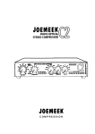
JOEMEEK TUBE CHANNEL
INSTRUCTIONS
The JOEMEEK TUBE CHANNEL VC2 is a development of historic tried and
tested circuits and designs from the 1960's to the present day, combined in a
single outboard rack unit by acknowledged leaders in analogue technology.
THE JOEMEEK TUBE CHANNEL - WHAT IT IS AND WHY
The JOEMEEK Tube Channel is the result of continuing experimental and
development work carried out over a 2 year period to incorporate the best of
historic design and tube technology as an extension of the development of the
other famous JOEMEEK products; the Stereo Compressor the Studio Channel
and the ProChannel.
It's best to think of the Tube Channel as four separate pieces of equipment:
1) The Microphone amplifier.
2) The Compressor.
3) The Enhancer.
4) The gain make-up.
VC2
1
The microphone amplifier takes the audio signals from any microphone
and amplifies them up to 'line' level; that is, from a few millivolts, up to
about a volt.
This function is not too difficult and the microphone amplifiers on normal
professional mixers do it quite well; BUT they cut costs and corners. The
JOEMEEK Tube Channel has an uncompromising old fashioned
approach, it uses a transformer at the input and two separate amplification stages
linked to provide lowest possible noise and distortion. By using the finest
components available for the purpose, and with proven high overload amplifier
design developed over many years, the performance is startlingly good.
The JOEMEEK Tube Channel is designed for the best capacitor microphones; it is
particularly good with the Neumann range, the AKG C3000 and C414, Microtech
Gefell, and Audio Technica.
Dynamic or ribbon microphones should be used with the phantom power turned
off, then full advantage can be taken of the extreme low noise performance of this
amplifier.
An unusual function switch is included on the rear panel for historic microphones;
this is an impedance conversion switch to optimise noise performance for elderly
ribbon and moving coil microphones which were designed to operate at 50 ohms.
Pressing in the 'hidden' switch, the impedance of the input is reduced to give an
improved transformer ratio for these microphones.
VOLUME
In normal use the JOEMEEK Tube Channel will work with any microphone and in
any audio environment. However, some capacitor microphones can produce
enormous output voltages when placed close to a loud sound source. To eliminate
any possibility of overload under these conditions, a 20dB pad switch is fitted.
NOISE
The combination of a good specially wound microphone transformer and 1996
spec. amplifiers makes the noise lower than other microphone amplifiers.
VC2
2
In practice, the only noise audible is the noise from the microphone itself (except the
characteristic tube noise in the line amplifiers).
PHASE SHIFT and QUALITY
It's Fletcher Company theory that 'big' sounds are only possible if the recording channel
keeps the response and phase of the lower frequencies flat and under control. To
achieve this, the JOEMEEK Tube Channel has an extended frequency range down
below 15Hz. This ensures that there are no sudden phase shifts in the low end. The
proof of the theory is that the sound from the Tube Channel is characteristically full
bodied and rounded in character.
Such extreme LF response can often bring its own problems so a 'subsonic' (High
Pass) filter can be switched in with a front panel push-button.
OVERLOAD MARGINS
In the mid 1970s Ted Fletcher designed a range of mixers specifically for use by the
Independent Broadcasting Authority and the BBC. One of the specification clauses
insisted on by them was an extreme overload margin in the microphone amplifier. The
reason was that although momentary overloads (transients) are not audible, they have
an effect on perceived quality. A high overload margin amplifier just sounds better.
Nowadays, many of these notions have been forgotten and 'quality' electronics is
getting rarer and rarer. But the JOEMEEK Tube Channel applies these professional
rules and achieves a clean transparent sound.
Line level inputs are plugged into the JOEMEEK Tube Channel via an XLR connector.
The line input is electronically floating balanced using the 'Superbal' electronic circuit
designed by Ted Fletcher in the mid 70's. The circuit gives excellent rejection of
electrical interference and produces an accurate line level signal.
PHASE
A push button is provided on the front panel to reverse the phase of all audio signals
(mic and line).
VC2
3
BALANCED AND UNBALANCED
The JOEMEEK Tube Channel is designed to be used in the best larger
studios where most (if not all) interconnections are 'balanced'. Balanced
operation means that the audio is carried on two wires working in opposite
phase. Then should any interference appear on the 'line', it will be
effectively cancelled out. Both of the main inputs (Microphone and Line) and the line
output are accurately balanced to get best advantage from true balanced operation; but
unbalanced operation (for line level signals) will NOT degrade the performance unless
very long cables are used (above 50 metres).
OPERATING THE MICROPHONE AMPLIFIER.
Press in the 'MIC/LINE' switch, (in for MIC and out for LINE). Turn the INPUT GAIN
knob down to minimum then, If you are using a capacitor microphone, plug in the
microphone, then switch on the phantom power by pressing in the 'Phantom' switch.
(Do it in that order).
NOTE. The phantom power supply takes several minutes to reach its working voltage.
Remember to switch on at least 5 minutes before using the microphone.
CAUTION. When using phantom power, DO NOT USE UNBALANCED
MICROPHONES. It will damage (magnetise) the input transformer.
Turn up the INPUT GAIN until sound registers on the VU meter (VU switch in). Do not
let the VU needle hit the end stop too hard or overload may possibly happen. The meter
electronics has been adjusted so that it is normal for the needle to move in the red area.
OVERLOAD MARGIN AND THE VU. METER
For steady tones, the '0' on the VU meter corresponds to approximately 0dBu (Where
0dBu is 0.775v RMS on the line output with the output control set at '0')
This setting of '0' is to allow for the considerable under-read that occurs with all VU
meters with music signals. It is normal for the peaks of signals to go to +10dBu while
the VU meter reads only '0'.
In practice, when the VU meter is peaking at or just above '0' the music signal will be
well within normal limits and will have a significant overload margin.
VC2
4
Even with the needle hitting the end stop, the signal will not be distorted;
although the overload margin will be reduced. (The VU meter is connected before the
output gain control)
THE JOEMEEK Tube Channel COMPRESSOR.
And now for the part of the JOEMEEK Tube Channel that gives it character;
THE COMPRESSOR.
The compressor is a photoelectric device where the sound triggers light emitting diodes
which in turn control the resistance of a photo sensitive resistor. This form of
compression used to be common in the 60's and 70's but has been superseded by so
called 'improved' voltage controlled amplifiers.
The advantages of the older system are that distortion is virtually nil, noise is extremely
low while overload margin is extremely good. The disadvantages are that the design is
more difficult to produce cheaply and, according to those who judge equipment by
specifications and not by listening, the older design is less flexible in operation and
more difficult to use (!)
Using 1990's electronics for the control circuitry, Ted Fletcher has recreated the
compressed sound of the 60's; a sound that was unlikely ever to be heard again.
Totally unlike a modern compressor, it can pull voices forward, help with internal mix
balance, and add 'presence' to the sound as well as controlling recording volume levels.
But its main and unique attribute is its ability to produce the characteristic 60's
compressed exciting sound without losing the transient sparkles that are such a feature
of good digital recording.
THE COMPRESSOR; TECHNICALLY.
To get the best use out of the compressor it is necessary to understand the
basic physics and what it is designed to do.
A LIMITER is a device which stops the output of a signal path going above
a predetermined level.
VC2
5
A COMPRESSOR is a device which reduces the dynamic range of
programme material.
WHAT IS A COMPRESSOR?
A perfect compressor is an amplifier where the input/output ratio is constant: So using a
2:1 compressor, increasing the input by 2dB gives a corresponding 1dB increase in the
output. Early compressors which used variable mu thermionic tubes or photoelectric
devices only approximated true compression over a limited range. They had a soft
'threshold' where compression started and held to a predictable ratio up to a certain
level, then they returned to a more linear amplification allowing transients through. This
is in stark contrast to modern VCA compressor/limiters where designers latched onto
the idea that a compressor should be entirely linear in its compression characteristic
(regardless of the sound produced) and thought it 'sensible' to combine the functions of
compressor and limiter to 'stonewall' any and all signals above a certain level.
The musical effect is that VCA compressors sound muddy and flat, while the historic
compressors sound lively and retain sparkle.
But all compressors change the sound to some extent. The JOEMEEK Tube Channel
compressor adds 'punch' and 'bite' without the dull muddiness of all others.
USING THE COMPRESSOR.
A compressor IN/OUT switch is fitted. When this switch is pressed the LED indicator
alongside switches off in preparation for a red "compression" signal.
To USE the compressor, set the COMPRESSION control to somewhere near full up.
Set ATTACK to minimum (full anticlock) and RELEASE to halfway. Switch the VU meter
to "COMP. METER" (switch out).
If there is sufficient audio signal from the input amplifiers, the meter will start to indicate
compression by the needle moving downwards. The compressor should now be
working and ears can take over the adjustments.
VC2
6
The amount of compression in use can be seen from the VU meter; but also the
flickering red LED is fitted to show the depth of compression;-this is particularly useful
during a busy session!
STEREO LINKING
On some units only a stereo link socket (phono socket) is fitted to the rear panel. To link
two units fit a screened single phono to phono cable between the two link sockets. This
will link the two compression sidechains BUT DOES NOT GUARANTEE ACCURATE
GAIN REDUCTION between the two channels. The reason for this is that the
photoelectric compressor relies on the linearity of selected light dependent resistor cells
which are never exactly the same. It is likely that stereo matching of within 1dB can be
achieved with any two units but this cannot be guaranteed. When using the units as
stereo pairs, make sure that the settings on the two units are the same.
CONTROL EXPLANATIONS
'COMPRESSION' simply adds gain to the compression sidechain and so increases
compression. In simple terms this changes the 'threshold' of the compression although
with this compressor the 'threshold' is not clearly defined; the compression starts very
gradually and the compression ratio changes radically with programme content and
amplitude. For practical purposes, winding up the compression control increases the
amount of compression. In use, all controls are interrelated.
'SLOPE' This switch controls the ratio of compression. In practice, 'COMP 2 is very
gentle compression while COMP 1 can give 'pumping' effects. It is advisable to keep
compression to a minimum during recording. The most effective way of using
compression is during the mixdown process.
VC2
7
'ATTACK' sets the time that the compressor takes to act. At minimum
(fastest) it is possible to make it 'overshoot' on some percussive programme
material: This means that the compression electronics are driven hard
before the gain has been controlled by the light cells. The cells catch up and
overcompress momentarily giving a tiny dip immediately following the start of
the 'note'. This is best demonstrated when recording drums. With Slope set to COMP 1,
and attack and release to fastest. Used sparingly this can contribute to musical drive.
Slower attacks are used where the compression needs to be less obvious.
'RELEASE' sets the time during which the path gain returns to normal after
compression. Generally, the longer the time, the less obvious is the compression.
AMOUNTS OF COMPRESSION
There can be no rule as to the correct amount of compression for any particular
programme material. Compression (particularly the JOEMEEK compressor) is a
creative effect for the producer. In rock music, it is possible to use considerable
amounts of compression (10dB or more) and still for the effect to be slight, in classical
recording, conventional compression is frowned upon but the JOEMEEK compressor
can be used to great effect if handled gently.
COMPRESSION PROBLEMS
1) Got signal going through but no compression.
Is the compressor switched in?
Is there enough signal? A high signal is required to make the compressor operate. Have you turned the
COMPRESSION control high enough? The normal place for the compression control is near or at full up.
2) It's noisy.
The compressor itself is extremely quiet, but by definition compressors raise the level of quiet passages;
this also means that if there is noise in the microphone channel (in the audio signal that is being
amplified), there will be more noise on the compressed signal. It's a compromise.
3) It distorts.
VC2
8
No it doesn't! Distortion inside the compressor is virtually impossible, however it is possible that the
microphone amplifier is set with too much gain; turn down the COMPRESSION control and readjust the
microphone amplifier gain.
VC2
9
4) I can't make the compression gentle enough!
It takes practice. The setting of the Attack control close to fastest is quite critical, as is the
compression control.
WHAT IS AN ENHANCER?
An enhancer (or exciter) adds a particular type of sparkle to sounds, particularly voices.
It appears to create brightness from sounds that were 'flat'.
The enhancer in the JOEMEEK Tube Channel (in common with the other JOEMEEK
enhancers) works by picking off the higher frequency part of the sound, compressing
and dynamically altering it, filtering off the original sound and remixing the resulting
harmonics back with the signal.
It adds high frequency sparkle, making singing voices sound more present and exciting
without some of the other hissy effects you get from simply turning up the HF equaliser.
It is the supreme 'suck-it-and-see' device. Used properly it can create beautiful sounds.
Overused it can be horrible.
USING THE ENHANCER.
Once a signal is going through the Tube Channel, press the 'ENHANCE' push-button
(which changes the 'en' LED from green to red), turn up the 'DRIVE' control until the
Enhance LED just starts to change colour or brighten on peak sounds.
Turn up the ENHANCE control until the sharpening of the sound is obvious, then adjust
the 'Q' control and the 'DRIVE' control to get the required effect.
Like the Compress control, the ENHANCE control just adds the enhancement so if it is
turned to minimum there is no effect.
Once the effect is audible, experiment with the three controls to get the desired sound,
the controls are very much interdependent and musically related.
'DRIVE' affects the depth and 'tone' of the enhancement.
RESONANCE or 'Q' affects the length of the high frequency harmonic after the syllable
that created it.
CAUTION. If in any doubt at all, leave enhancement till the mixdown; its easy to put on
but impossible to take off!
VC2
10
NOISE IN THE ENHANCER
Under many normal conditions of use, the enhancer has the effect of
amplifying selected narrow frequency bands in the upper mid range. The
danger is always to overuse the enhancer: This has the effect that any noise
sounds particularly 'scratchy'. The problem is that the existence of these
frequencies is common in quality
recording. The effect can be reduced to almost nothing with careful use of the drive and
enhance controls; but it does take practice.
THE TUBE (THE MAKE-UP AMPLIFIER)
The photoelectric compressor attenuates (reduces the volume of) the audio signal. This
gain loss has to be made up in an amplifier. Normally this amplifier is solid state and
adds no noise or distortion of any sort. In the JOEMEEK Tube Channel the amplifier
used is a thermionic tube. This old technology is used to produce a particular sort of
'warm' sound that is a product of the way thermionic tubes work.
TUBE DISTORTION
All amplifiers produce distortion of some sort. Modern solid state circuits have
effectively eliminated distortion down to such low levels that they are very difficult to
detect. However, such distortions that are left are basically 'third order', these are
distortions that impose microscopic additions to the sound in an unmusical way; that is
the distortion products are not musically related to the original audio signal.
Unfortunately for electronics designers, the human ear is extremely good at noticing
these very low levels of distortion and recognising them as ‘unpleasant'. This is why all
early 'transistor' radios had such a bad reputation for sounding nasty.
But not all audio distortion is unpleasant; the tiny distortions produced by thermionic
valves (or tubes) is basically second order distortion, harmonically related to the audio
signal and pleasant to listen to. So what little distortion is produced by a well designed
tube amplifier is good to listen to and actually enhances the 'quality' of the sound;
although when it is measured on sophisticated test equipment, it will actually show a
higher harmonic distortion figure!
VC2
11
The tube make up amplifier in the JOEMEEK Tube Channel has been optimised to
produce minimal noise and distortion, but the remainder distortion in the system is
second order and this is one of the reasons that the sound of the Tube Channel is warm
and pleasant.
TUBE NOISE
The characteristic sound of the noise produced by a tube amplifier is very unlike the
noise in a solid state amplifier. The frequency spectrum is different and this contributes
psychoacoustically to the 'warm' sound of the Tube Channel.
USING THE INS AND OUTS
MICROPHONE.
The microphone input is an XLR connector. The microphone used should be balanced
200 ohm impedance (or 50 ohm impedance; impedance select switch).
Connections are;
•
Pin 1 is ground or screen.
•
Pin 2 is positive phase or 'hot'
•
Pin 3 is negative phase (or ground for unbalanced).
To avoid impulsive 'clonks' and the possibility of causing magnetising in the microphone
input transformer, plug in capacitor microphones before turning on the phantom power.
LINE INPUT.
The line input is a high impedance floating balanced input suitable for any line level
audio signal. The line input is disabled when 'mic' is selected by the mic/line switch and
vice-versa.
INSERT POINT.
This is used to insert another effect or outboard equipment into the Tube Channel. The
microphone/line amplifier output appears on the tip of the 1/4 inch jack socket, the 'ring'
is the return input. When no jack is inserted, the socket is 'normalled' (internally linked).
MIX INPUT.
This is an auxiliary 1/4 inch jack unbalanced line level input which mixes with the
normal mic or line. This input is immediately before the compressor.
VC2
12
OUTPUTS
A single 1/4 inch jack socket provides high level balanced line output.
The two XLR output sockets are balanced low impedance, and are resistor
buffered from each other. The 'HIGH LEVEL' output is low impedance
balanced output at zero level. The 'LOW LEVEL' output is 200 ohm
impedance microphone level (-40dB).
Connections are;
•
Pin 1 is ground or screen.
•
Pin 2 is positive phase or 'hot'
•
Pin 3 is negative phase (or ground for unbalanced).
Output balancing is achieved electronically and these outputs behave in a similar way
to transformers.
POWER
Mains input is 230/110V AC via the IEC socket. The socket has an integral fuse holder
with a spare fuse fitted. Rotation of the fuse holder selects alternative AC voltage.
VC2
13
TECHNICAL SPECIFICATION.
MICROPHONE INPUT.
•
•
•
•
•
•
•
XLR Input 3Kohm and 800 ohm (switchable to suit 200 ohm and 50 ohm microphones).
Transformer balanced and floating. Switchable 48V phantom power.
Input level from -80dB to 0dB (20dB pad switch)
Push button 200/50 ohm source switch (on rear panel).
Push button MIC/LINE switch.
Push button 20dB pad switch.
Push button 48V phantom supply switch with LED indicator.
LINE INPUTS.
•
•
XLR 10K impedance floating balanced.
Mix input unbalanced 10K impedance.
OVERLOAD MARGIN.
•
30dB on Mic and Line inputs in normal operation.
GAIN.
•
•
•
•
Line in -6dB to 24dB
Mic in 15dBto 68dB
Insert gain 0dB
Mix in gain 0dB
NOISE.
•
•
Line in 80dB below operating level
Mic in 125.5dB below input at 50dB gain 20Hz to 20KHz.
HARMONIC DISTORTION.
•
Generally within 0.05% rising to approx. 0.14% at 4dB above nominal output level. 2nd harmonic
predominant.
AMPLITUDE FREQUENCY RESPONSE
•
•
•
Line in 10Hz to 15KHz within 0.5dB
Mic in 10Hz to 15KHz within 1dB
High pass filter 3dB down at 25Hz, 12dB per octave.
PHASE REVERSE.
•
Push button phase reverse switch and LED indicator; reverses phase of all signals.
FILTER.
•
Push button high pass filter switch (andindicator) operates at 25Hz at 12dB per octave.
VC2
14
INSERT.
•
Push putton insert switch (and indicator)allows comparison of inserted outboard
equipment.
OUTPUTS
•
•
•
•
XLR High level balanced 50 ohm +4dBu for 0VU (variable)
Max. output unbalanced approx. +22dBu, balanced +26dBu.
XLR Low level balanced 200 ohm -40dBu
Insert, Tip and Ring jack socket. 400 ohm -10dBu output, 22K ohm input.
COMPRESSOR
•
•
•
•
•
Photoresistive servo operated with 2 stage tube amplifier.
Ratio 1 approx. 5 to 1 (ratio switch)
Ratio 2 approx. 3 to 1
Attack time 1mS min. 7mS max. (variable).
Release time 200mS min 3S max. (variable).
ENHANCER
•
Performance details not released.
POWER
•
•
•
Approx. 15 Watts.
IEC socket for power cable.
Reversible fuse holder for 230VAC and 110VAC power input.
HOUSING
•
•
•
21) rack mounting totally enclosed steel case.
depth approx.
350mm.
weight
2.5Kgs.
WARRANTY.
In the unlikely case of a breakdown, please return the unit in its original packing through
the supplier. The unit will be attended to immediately and returned to your supplier. If
any breakdown occurs (excluding physical mistreatment) within 12 months of purchase
no charge will be made.
DECLARATION OF CONFORMITY.
This analogue audio processing equipment conforms to the standards and
requirements of the European Economic Community.
The EC Harmonised standards that have been applied are;
a) Electrical equipment (safety) Regulations 1994 (S.I. 1994/3260)
b) Electromagnetic Compatibility Directive (89/336/EEC) incorporating (S.I.
1992/2372)
1998
VC2
Distribution by JOEMEEK Distribution
Phone : +44 (0)1626 333948
Fax: +44 (0)1626 333157
15
Worldwide distribution by:
JOEMEEK Distribution,
Quay House,
Quay Road,
Newton Abbot,
Devon. TQ12 2BU.
ENGLAND.
Tel:
+44 1626 333948
Fax:
+44 1626 333157
email: [email protected]
www.joemeek-uk.com
VC2
16