1
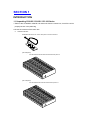
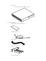
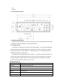
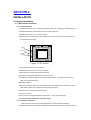
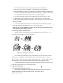
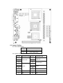
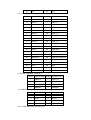
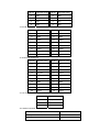
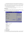
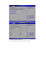
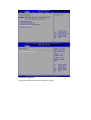
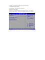
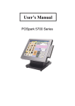
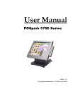
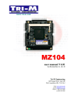
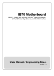
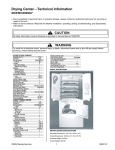
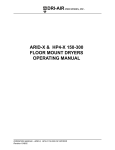
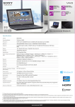
CS & CD Series
User’s Manual
Installation Guide Revision JU21
Contents
SECTION 1 INTRODUCTION
1.1 Unpacking CS-00B / CS-10B / CD-10S Series
1.2 Description
1.3 Features
1.3.1 Graphic
1.3.2 HDD
1.3.3 Ethernet
1.3.4 I/O connectivity – ICH4
1.3.5 I/O Shield Connector
1.3.6 Hardware Monitoring
1.3.7 Power-On Off
1.4 Specifications
1.5 Mechanical Dimensions
SECTION 2 INSTALLATIONS
2.1 System Installation
2.1.1 Motherboard Installation
2.1.1.1 CPU Installation
2.1.1.2 HeatPipe Installation
2.1.1.3 Memory Module Installation
2.1.1.4 Setting Jumpers and DIP Switches
2.1.2 Chassis Installation
2.1.2.1 Motherboard Mounting Installation
2.1.2.2 HardDisk / DVD Dive Installation
2.1.2.3 PCI Riser Card Iinstallation(for CD-10B only)
2.2 Board layout
2.3 Jumper Setting
Section 3 BIOS SETUP
3.1 BIOS Instructions
3.2 Main Menu
3,3 Advanced Menu
3.3.1 Configure advanced CPU settings
3.3.2 Configure Win627THF Super IO Chipset
3.3.3 Hardware Health Event Monitoring
3.3.4 ACPI Configuration
3.3.5 USB Configuration
3.3.1 Chassis Installation
3.3.1 Chassis Installation
3,4 Boot Menu
3,5 Security Menu
3,6 Power Menu
3,7 Exit Menu
3.7.1 Save Change and Exit
3.7.2 Discard Change and Exit
SECTION 1
INTRODUCTION
1.1 Unpacking CS-00B / CS-10B / CD-10S Series
1.Take out the CS-00B/CS-10B/CD-10S series unit from the carton box, check if the unit is
properly secure in the pearl bag
2.Check the contents of the carton box:
a.
Chassis main box
–
Embedded 90W DC-to-DC 19V-to-ATX power conversion board x1
–
(CS-00B option):
–
–
CS-00B chassis without DVD-slot-reserved front panel x1
(CS-10B option):
–
CS-10B chassis with DVD-slot-reserved front panel x1
–
(CD-10S option):
–
b.
CD-10S chassis with DVD-slot-reserved front panel x1
Chassis accessory box
–
120W AC-to-DC(AC110/220V to DC19V) adaptor x1
–
AC110/220V power cord x1
–
ATX power cord x1
–
Heatpipe(Intel / VIA ) x1
–
(CS-10B/CD-10S option):
R
R
–
–
c.
DVD Back Panel connector with 2 screws x1
Part bag x1
1.
Screws for 3.5”HDD(6-32*5) x4
2.
Screws for 2.5”HDD(M3*5) x4
3.
Screws for DVD(M2*3) x4
4.
Screws for motherboard(M3*5) x4
5.
Heatsink for northBridge x1
6.
Plastic fan fixators for VIA motherboard x2
7.
Plastic fillets x3
8.
Plastic fillet fixator x2
9.
Heat sink compound injector x1
10.
Heat sink sticker x1
Industrial motherboard PWI-8552 box
–
Industrial Motherboard PWI-8552 x1
–
ATA-33/66 HDD bus cable x2
–
Com port cable(for RS-232) x1
–
Back IO-Shield x1
–
Fan/Heatpipe fixing screwsets(screws and nuts) x4
–
Driver CD x1
1.2 Description
The CS-00B / CS-10B series combine the high performance and exceptional value of
IntelR 855GME chipset with a full-featured, new generation, industrial motherboard, housed in
sleek and stream-lined Chassis CS-00B / CS-10B. IntelR advanced 855GME chipset support
socket 478-pins Intel Pentium-M/Celeron-M processor of 1.3GHz and up to 2.0GHz(DothanTM
Core), that memory base on the FSB 400MHz operation supports DDR SDRAM interface.
The PWI-8552 system memory size can be up to 1GB DDR memory, with onboard one 10/100
RJ45 ethernet connector, Audio Line-out and one COM ports. Because the PWI-8552 with four
USB2.0 ports on the rear panel and two internal USB2.0 ports. They are for high-end
applications
The I/O Controller Hub(ICH4) employs the IntelR Accelerated Hub Architecture to make a
direct connection from the graphic and memory, the IDE controllers(ATA/33 or ATA/66), six
USB ports that are supported USB1.1/2.0 standard meets the performance, stability and
reliability requirements.
As for its chassis CS-00B / CS-10B, the 00B series is designed for 3.5” HDD and the
10series is designed for both 2.5”HDD and DVD player/burner.
This Mini system is well supported with the WindowsR 98/2000/XP/NT and LinuxR
operation system.
1.3 Features
1.3.1 Graphic
DVI interface is especially for digit video output
1.3.2 HDD
2 SATA connector
2 ATA IDE connectors
1.3.3 Ethernet
10/100 RJ45 x1
1.3.4 I/O connectivity – ICH4
6 hi-speed USB 2.0DVI interface
7.1 channel(Realtek 850) with S/PDIF RCA connector
DB9 RS-232 / RS-485 Pin Header
6-pin SIR / ASKIR
S-Video
YPbPr RCA connector
PCI
Mini PCI
1.3.5 I/O Shield Connector
1.3.6 Hardware Monitoring
Hardfware monitoring allows you to monitor various aspects of your system operations and status .
The features include CPU temperature, voltage and RPM of fan.
1.3.7 Power-On Off
The board has a single 20-pins connector for ATX power supplies. For ATX power supplies that
support the Remote On/Off feature(Watch Dog Support), this should be connected to the systems
front panel for system Power On / Off button.
The systems power
On / Off button should be a
momentary button that is normally open.
The board has been designed with “Soft Off” functions. You can turn off the system from one of
two sources: The first is the front panel Power On / Off
the putton, and the other is the “Soft Off”
function(coming from the M/B onboard circuit controller) that can be controlled by the operating
R
R
system such as Windows 98 / 2000 / XP / NT or Linux
1.4 Specifications
Form Factor
Mini-ITX ( 170mm x 170mm)
Processor
Intel Pentium-M/ Celeron-M
Chipset
855GME + ICH4
Memory
Max. 1GB DDR333 DIMMx1
Ethernet
10/100 RJ45 x1
IEEE 1394
IEEE 1394 x 1
VGA
DVI-I X 1
TV-out
S-Video (connector) x 1; RCAx1
USB support
USB 2.0 x 6 (Pin Head X 2; Connector X 4)
SPDIF
SPDIF coaxial RCA Connector x 1
Bus Expansion
PCI X 1, Mini PCI
Serial Ports
DB9 RS-232/ RS485 X 2/ Pin Header (BIOS Select)
GPIOs
4in/ 4out, TTL level pin header
IDE Support
Dual IDE , 4 drive support, Ultra DMA 33 / 66
SATA
SATA connector X 2
Audio
7.1 channel (Realtek 850) S/PDIF RCA connector x 1, Stereo Out, Line
Out, Mic In, Line In via stacked audio jacks x 1
IrDA
6-pin SIR/ ASKIR (BIOS Select)
LEDs & Switches
Reset switch;Power & HDD LEDs via ATX enclosure compatible
interface
Power Management ACPI 1.1; Power button support; no individual device control
Power Input
ATX Power connector x1
Speaker
Pin Header
Operating
0 to 50°C
Temperature
Relative Humidity
5% to 90% non-condensing
Watch DOG Support Yes
I/O shield
Standard I/O
1.5 Mechanical Dimensions
170mm
170mm
SECTION 2
INSTALLATION
2.1 System Installation
2.1.1 Motherboard Installation
2.1.1.1 CPU Installation
1.Check and confirm that you are going to install correctly CPU type and pin numbers(Figure 1)
2.Take the screwdriver and releasing screw-nut of the socket 478
3.Rotate mark of screw-nut to face the “OPEN”
4.Align the pins of the CPU against the pinholes of the socket 478. Be sure to pay attention to
the orientation of the CPU
OPEN
SCREW NUT
CLOSED
Figure 1:CPU Socket
5. Push down the CPU into the socket 478
6.Rotate mark of screw-nut to face the “CLOSED”
7.Place the CPU cooling fan atop the CPU surface
8.Push down the opposite side of the ZIF clip and hook it
9.Connect the cooling fan cable to the socket as shown below.
Be careful not to place the
cable on the CPU cooling fan
Removing a CPU
1.Before removing the CPU, turn off the system power; then wait for about 20 minutes until the
heat radiation plate of the cooling fan and the CPU cools down
2.Rotate mark of screw-nut to face the “OPEN”
3.To remove the CPU
NOTE: The CPU and the heat radiation plate are hot. They may cause burns
To remove the CPU, reverse the installation steps
2.1.1.2 HeatPipe Installation
Make sure that good contact is made between the processors and the heatpipe.
Insuffucuent contact, incorrect types of heatpipe or thermal compound used or improper amount
of thermal compound applied on the CPU die can cause the processors to overheat, which may
crash the system.
Figure 2:HeatPipe Installation
2.1.1.3 Memory Module Installation
Figure 3 display the notch marks and what they should look like on your DIMM memory
module. DIMM have 184-pins and two notches, that will match with the onboard DIMM socket.
DIMM modules are installed by placing the chip firmly into the socket at a 90-degree angle and
pressing straight down(figure 4) until it fits tightly into the DIMM socket
Figure 3:DIMM Memory and 184-pins Socket
Pull it
Pull it
Figure 4:Memory Installation
Carefully follow the steps below in order to install the DIMMs:
1. To avoid generating static electricity and damaging the DIMM, ground yourself by touching a
grounded metal surface or using a ground scrap before you touch the DIMM
2. Do not touch the connector of the DIMM.
Dirt residue may cause a malfunction
3. Hold the DIMM with its notch to the front side of the motherboard and insert it completely into
the socket.
A DIMM should be inserted into the inner socket first. Suiding the hole at each
end of the DIMM over the retaining post at each end of the DIMM socket
4. If you install two DIMMs, install the second DIMM using the same procedure as above
5. If DIMM does not go in smoothly, do not force it. Pull it all the way out and try again
6. Make sure the DIMM is properly installed and looked by the tabs on both sides of the socket
Removing a DIMM
To remove the DIMM, use your fingers or a small screwdriver to carefully push away the
plastic tabs that secure the DIMM at each end.
Lift it out of the socket.
Make sure you store the DIMM in an anti-static bag and must be populated the same size
and manufactory of the memory modules
2.1.1.4 Setting Jumpers and DIP Switches
There are jumpers and DIP-switches on the Embedded Board of the motherboard. You
can set the jumpers to make the necessary operations.
Figure 5:Jumper Connector
For any three-pins jumpers(figure 5), the jumper setting is 1-2 when the jumper connects
pin1 and pin2. The setting is 2-3 when pin2 and pin3 are connected and so on. You see a
number “1” and a “3” printed on the circuit board to identify these pins.
And also, there is a second
way of indication – one of the lines surrounding jumpers is thick, which indicates pin NO.1.
To remove a jumper from one position to another, use needle-nose pliers or tweezers to pull
the pin cap off the pins and move it to the desired position.
2.1.2 Chassis Installation
2.1.2.1 Motherboard Mounting Installation
After finishing the installation of motherboard, what we have to do next is to mount the
installed motherboard onto chassis CS-00B / CS-10B. Steps are as follows:
1.Open the lid of chassis
2.Install the back I/O shield of motherboard first; please insert it onto the chassis back open frame
3.Place the installed motherboard to align with the screw holes on the chassis floor; once mounted,
then screw the motherboard’s 4 cornors onto chassis.
Be aware: during placing the motherboard onto chassis, the installed heatpipe could be a
obstacle for that. Try some pushing and pulling to set the heatpipe to its correct
notching position
2.1.2.2 HardDisk / DVD Dive Installation:
1.Uninstall the harddisk rack from the chassis
2.Mount the HDD / DVD Drive:
– (CS-00B/CD-10S option): only 3.5”HDD can be installed
i. Take out the 3.5” HDD left and right brackets from accessory pack
ii. Screw them to the HDD brace
iii. Mount the HDD to that screwed bracket on the brace
iv. Screwdrive the HDD with the proper attached screws
v. Connect the IDE cable to 3.5”HDD
vi. Connect the big 4P power cable to to 3.5”HDD
– (CS-10B/CD-10S option): 2.5”HDD and DVD drive can be installed
[2.5”HDD]:
i.
Uninstall HDD brace from chassis
ii.
Screw the 2.5” HDD onto back(lower) side of the brace
iii. Mount the 44pin-to-40pin connecting adaptor to 2.5”HDD
iv. Connect the IDE cable to that connecting adaptor
v.
Connect the big 4P power cable to that connecting adaptor
[DVD drive]:
i.
Screw the DVD Drive onto the front(upper) side of the brace
ii.
Mount the DVD back panel to DVD drive
iii. Connect the IDE cable to that back panel
iv. Connect the small 4P power cable to that back panel
v. Re-install HDD brace back to its original chassis position
3.Connect the HDD/DVD drive IDE cable to individual motherboard IDE slot
2.1.2.3 PCI Riser Card Iinstallation(for CD-10B only)
1.remove the chassis back PCI fixing screw
2.plug in the PCI card into the one of the 2 PCI slot on that PCI riser card
3.fix the PCI card onto the chassis back open slot(reserved for PCI card installation)
4.screw the PCI fixing screw again to stabilize the PCI card
.
2.2 Board layout
.
2.3 Jumper Setting
JP2: Clear CMOS Setup
JP2
DESCRIPTION
1-2
Normal Operation (Default)
2-3
Clear CMOS Setup
J19: System Panel Connectors
PIN NO.
DESCRIPTION
1
3
PIN NO.
2
Power LED
6
7
8
Buzzer
HDD LED
4
5
9
DESCRIPTION
10
Power Button
Reset
11
12
13
14
N/A
15
N/A
16
N/A
17
N/A
18
N/A
19
N/A
20
N/A
J13, J12: Primary/ Secondary IDE Interface Connector
PIN NO.
DESCRIPTION
PIN NO.
DESCRIPTION
1
RESET#
2
GROUND
3
DATA 7
4
DATA 8
5
DATA 6
6
DATA 9
7
DATA 5
8
DATA 10
9
DATA 4
10
DATA 11
11
DATA 3
12
DATA 12
13
DATA 2
14
DATA 13
15
DATA 1
16
DATA 14
17
DATA 0
18
DATA 15
19
GROUND
20
N/C
21
IDE DRQ
22
GROUND
23
IOW#
24
GROUND
25
IOR#
26
GROUND
27
IDE CHRDY
28
GROUND
29
IDE DACK
30
GROUND–DEFAULT
31
INTERRUPT
32
N/C
33
SA1
34
N/C
35
SA0
36
SA2
37
HDC CS0#
38
HDC CS1#
39
HDD ACTIVE#
40
GROUND
J11A/J15B: USB PART Connector
PIN NO. DESCRIPTION PIN NO. DESCRIPTION
1
USBVCC1
1
USBVCC2
2
D1F-
2
D2F-
3
D1F+
3
D2F+
4
USBGND1
4
USBGND2
J14: USB Connector
PIN NO. DESCRIPTION PIN NO. DESCRIPTION
1
USBVCC
1
GND
2
DATA4-
2
DATA5+
3
DATA4+
3
DATA5-
4
GND
4
USBVCC
J15A: 100M-LAN RJ45 PART Connector
PIN NO.
DESCRIPTION
PIN NO.
DESCRIPTION
1
TX+
6
N/C
2
TX-
7
RX-
3
RX+
8
N/C
4
N/C
9
N/C
J10/J11B: 1394 PART Connector
PIN NO. DESCRIPTION
PIN NO. DESCRIPTION
1
12V
1
12V
2
GND
2
GND
3
TPB1-
3
TPB0-
4
TPB1+
4
TPB0+
5
TPA1-
5
TPA0-
6
TPA1+
6
TPA0+
7
Chassis GND
7
Chassis GND
8
Chassis GND
8
Chassis GND
J5: ATX Power Connector
PIN NO. DESCRIPTION
PIN NO. DESCRIPTION
11
NC
1
NC
12
-12V
2
NC
13
GND
3
GND
14
PS_ON
4
VCC5
15
GND
5
GND
16
GND
6
VCC5
17
GND
7
GND
18
NC
8
NC
19
VCC5
9
5VSB
20
VCC5
10
VCC5
J1/ J2: Fan Connector
PIN NO.
DESCRIPTION
1
Fan Speed Detect
2
+12V
3
GND
J24: Audio Connector
Center/Subwoofer Speaker Out : ORANGE
LINE IN: BLUE
Rear Speaker Out : BLACK
LINE OUT: GREEN
Side Speaker Out : GRAY
MIC IN: PINK
J4: IR
PIN NO. DESCRIPTION
PIN NO. DESCRIPTION
1
VCC5
2
IRTX
3
CIR
4
IRRX
5
GND
COM1: Serial Port Connector (2*5-10pin 2mm Header)
PIN NO. DESCRIPTION
PIN NO. DESCRIPTION
1
DCD
6
CTS
2
DSR
7
DTR
3
RX
8
RI
4
RTS
9
GND
5
TX
10
GND
COM2: Serial Port Connector (2*7-14pin 2mm Header)
PIN NO. DESCRIPTION
PIN NO. DESCRIPTION
1
DCD
8
RI
2
DSR
9
GND
3
RX
10
GND
4
RTS
11
TX+
5
TX
12
TX-
6
CTS
13
RX+
7
DTR
14
RX-
J30: Audio Connector
PIN NO. DESCRIPTION
PIN NO. DESCRIPTION
1
LINE IN R
2
LINE IN R(J24 JUMPER)
3
LINE IN L
4
LINE IN L(J24 JUMPER)
5
Gnd
6
Gnd
7
LINE OUT R
8
LINE OUT R(J24 JUMPER)
9
LINE OUT L
10
LINE OUT L(J24 JUMPER)
11
GND
12
GND
13
Front MIC1
14
Front MIC2
SECTION 3
BIOS SETUP
3.1 BIOS Instructions
AMI;s ROM BIOS provides a built-in Setup program, which allows user to modify the basic
system configuration and hardware parameters. The modified data will be stored in a battery-backed
CMOS, so that data will be retained even when the power is turned off. In general, the information
saved in the CMOS RAM will stay unchanged unless there is a configuration change in the system,
such as hard drive replacement or a device is added.
It is possible for the CMOS battery to fail, this will cause data loss in the CMOS only.
If this
does happen you will need to reconfigure your BIOS settings.
3.2 Main Menu
Once you enter the AMI’s BIOS COMS Setup Utility, the Main Menu will appear on the screen.
The Main Menu gives you the overview information of current hardware and device. Use the arrow keys
to select among the items and press <Enter> to accept and enter the sub-menu.
AMIBIOS:
Version/date/ID of this BIOS built
Processor:
Working CPU speed/Type
System Memory:
System memory size
System Time:
Adjust to correct time
System Date:
Adjust to correct date
3.3 Advanced Menu
This feature allows you to configure your system for basic operation. You have the opportunity
to select the system’s default speed, boot-up sequence, keyboard operation, shadowing and security.
CPU Configuration:
Configure CPU feature
SuperIO Configuration:
Configure serial port feature
Hardware Health Configuration:
Configure CPU/system working situation feature
ACPI Configuration:
Configure system power management feature
3.3.1 Configure advanced CPU settings:
Display CPU more detailed information and configure CPU special feature
3.3.2 Configure Win627THF Super IO Chipset:
Configure serial port transportation method for RS2323/485/422 and COM port feature
3.3.3 Hardware Health Event Monitoring:
Monitor CPU/system temperature, CPU fan speed, and CPU voltage
3.3.4 ACPI Configuration:
Configuration ACPI advanced power management setting
3.3.5 USB Configuration:
USB port type(1.1/2.0) selection and port number selection
3.4 Boot Menu
This feature allows you to set which device bootable. The system searches all possible
locations for an operation system if it fails to find one in the devices specified under the first, second, and
third boot device.
3.5 Security Menu
This feature allows you to set either supervisor or user password, or both of then. The
difference between are:
Change Supervisor Password: can enter and change the options of the setup menus
Change User Password: just only enter but do not have the right to change the options of the
setup menus. When you select this function, the following message will appear at the center of the
screen to assist you increasing a password
3.6 Power Menu
The power menus allows you to configure you system to most effectively ave energy while
operating in a manner consistent with your own style of computer use
3.7 Exit Menu
3.7.1 Save Change and Exit:
Pressing <Enter> on this item asks for confirmation:
Save to CMOS and Exit (Y/N)? Y
Pressing “Y” stores the selections made in the menus in CMOS – a special section of
memory that stays on after you turn your system off. The next time you boot your
computer, the BIOS configures your system according to the Setup selections stored
in CMOS.
After saving the values the system is restarted again.
3.7.2 Discard Change and Exit:
Pressing <Enter> on this item asks for confirmation:
Quit without saving (Y/N)?
This allows you to exit Setup without stroing CMOS any change. The previous
selections remain in effect. This exits the Setuputility and restarts your computer