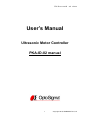
1
UPS-K10-11002B
3rd edition
User’s Manual
Ultrasonic Motor Controller
PKA-ID-02 manual
1
Copyright 2014, SIGMAKOKI Co.,Ltd.
UPS-K10-11002B
3rd edition
Notes regarding these materials
・ These materials are intended as a reference to assist our customers in the use of
the SIGMAKOKI CO., LTD. Product best suited to the customer’s application; they
do not convey any license under any intellectual property rights, or any other rights,
belonging to SIGMAKOKI CO., LTD. or a third party.
・ SIGMAKOKI CO., LTD. assumes no responsibility for any damage, or infringement
of any third-party’s rights, originating in the use of any product data, diagram, charts,
programs, or algorithms contained in these materials.
・ All information contained in these materials, including product data, diagrams,
charts, programs and algorithms represents information on products at the time of
publication of these materials, and are subject to change by SIGMAKOKI CO.,LTD.
without notice due to product improvements or other reasons.
・ When using any or all of the information contained in these materials, including
product data, diagrams, charts, programs, and algorithm, please be sure to evaluate
all information and products. SIGMAKOKI CO., LTD. assumes no responsibility for
any damage, liability or other loss resulting from the information contained herein.
・ SIGMAKOKI CO., LTD. products are not designed or manufactured for use in
equipment or system that is used under circumstances in which human life is
potentially at stake. SIGMAKOKI CO., LTD. products cannot be used for any
specific purposes, such as apparatus or systems for transportation, vehicular,
medical, aerospace, nuclear, or undersea repeater use.
・ The prior written approval of SIGMAKOKI CO., LTD. is necessary to reprint or
reproduce in whole or in part these materials.
・ If these products or technologies are subject to the Japanese export control
restrictions, they must be exported under a license Japanese government and
cannot be imported into a country other than the approved destination.
Any diversion or re-export contrary to the export control laws and regulations of
Japan and/ or the country of destination is prohibited.
2
Copyright 2014, SIGMAKOKI Co.,Ltd.
UPS-K10-11002B
3rd edition
Contents
For Your Safety __________________________________________________________ 4
Chapter 1
Before you begin___________________________________________ 5
1.Package contents ________________________________________________________ 5
2.Overview ________________________________________________________________ 5
3.Name of each part and function _________________________________________ 5
Chapter 2
Connection and Setting __________________________________ 7
4.PKA-ID-02 connection procedure________________________________________ 7
5.PKA-ID-02 Setting ______________________________________________________ 8
Chapter 3
PKA-ID-02 operation _____________________________________ 9
6. Controlling the ultrasonic motor (PKA series) by manual operation. ___ 9
7. Ultrasonic motor (PKA series) control by PC. ___________________________ 9
Chapter 4 Specification ________________________________________________ 13
8. Specification ___________________________________________________________ 13
9. Connector Pin Number ________________________________________________ 14
10. Outer dimension _____________________________________________________ 14
3
Copyright 2014, SIGMAKOKI Co.,Ltd.
UPS-K10-11002B
3rd edition
For Your Safety
● Before using this product, read this manual and all warnings or cautions in the documentation provided.
● Only Factory Authorized Personnel should be changes and/or adjust the parts of controller.
The Symbols Used in This Manual
!
WARNING
!
CAUTION
This symbol marks warnings that should be read and used to
This symbol indicates where caution should be used to avoid
prevent serious injury or death.
possible injury to yourself or others, or damage to property.
This symbol indicates where caution should be used to avoid possible injury to yourself or others, or damage to property.
Disclaimer of Liability
① SIGMAKOKI CO., LTD. does not accept liability for damages resulting from the use of this product or the inability to use this product.
② SIGMAKOKI CO., LTD. does not accept liability for damages resulting from the use of this product that deviates from that described in
the manual.
③ SIGMAKOKI CO., LTD. does not accept liability for damages resulting from the use of this product in extraordinary conditions,
including fi re, earthquakes, and other acts of God, action by any third party, other accidents, and deliberate or accidental misuse.
④ If the equipment is used in a manner not specifi ed by the SIGMAKOKI CO., LTD., the protection provided by the equipment may be
impaired.
!
!
WARNING
● Do not use this product in the presence of flammable gas, explosives,
CAUTION
●Because some electrical change remains after the power has been cut, do
or corrosive substances, in areas exposed to high levels of moisture or
not touch the input or output terminals for ten seconds after the product
humidity, in poorly ventilated areas, or near flammable materials.
has been turned off.
●Do not connect or check the product while the power is on.
●When connecting peripherals to the product, adjust the product's initial
●Installation and connection should be performed only by a qualified
setting (parameter settings) to suit the peripheral.
technician.
●Turn off the power before connecting the product to other devices.
●Do not bend, pull, damage, or modify the power or connecting cables.
Connection should be performed following the connection diagram.
●Do not touch the products internal parts.
●Before turning the equipment on (or when beginning operations), be
●Connect the earth terminal to ground.
sure that you can turn the power off immediately in the event that an
●Should the product overheat, or should you notice an unusual smell, heat,
abnormality should occur.
or unusual noises coming from the product, turn off the power immediately.
●Do not turn on the power in the event that it has received a strong physical
shock as the result of a fall or other accident.
●Do not touch the stage while operation.
●Use dry clothes only for cleaning the equipment.
●Do not leave the product in an enclosed area or in areas in which it would
be exposed to direct sunlight or vibration.
●Do not touch the product when your hands are wet.
4
Copyright 2014, SIGMAKOKI Co.,Ltd.
UPS-K10-11002B
Chapter 1
3rd edition
Before you begin
1.Package contents
Before you use this controller, check if your package includes all the items listed below. It is convenient to
check in the boxes: If your package does not include all the items, or items are
damaged, please contact us.
□PKA-ID-02 Controller
□Manual
The edition in memory switch of PKA-ID-02 controller can be done by sample software (SG Sample or
SG Commander). SG Sample and SG Commander is available for download from our website.
URL : http://www.sigma-koki.com
2.Overview
This controller is used for driving ultrasonic motor (PKA series).
With the connection with user PC through RS232C interface, user can send a simple command to control
ultrasonic motor (PKA series). Beside by PC, user can control manually by JOG switch as well.
3.Name of each part and function
3-1.Name of each part
⑥Axis1 connector
③JOG1 switch
⑦Axis2 connector
④JOG2 switch
①POWER LED
⑤SPDSEL switch
⑧Earth terminal
②RS232C connector
5
⑨Power terminal
Copyright 2014, SIGMAKOKI Co.,Ltd.
UPS-K10-11002B
3rd edition
3-2.Each part function
①POWER LED
:Light up in green when powered
②RS232C connector
:A control by PC through RS232C interface
③JOG1 switch
:Manual control to ultrasonic motor (PKA series) axis 1
④JOG2 switch
:Manual control to ultrasonic motor (PKA series) axis 2
⑤SPDSEL switch
:Switching speed for manual operation.
⑥Axis1 connector
:Connector for connection to ultrasonic motor (PKA series) axis 1
⑦Axis2 connector
:Connector for connection to ultrasonic motor (PKA series) axis 2
⑧Earth terminal
:Should be grounded properly in your environment
Caution
⑨Power terminal
Grounding properly in your environment is a must.
:Supply power by (DC+24V,2A)
Make sure to set up and wire the cable supplying DC+24V and GND to the PKA-ID-02 so
that the maximum length of cable is not longer than 2m.
6
Copyright 2014, SIGMAKOKI Co.,Ltd.
UPS-K10-11002B
Chapter 2
3rd edition
Connection and Setting
4.PKA-ID-02 connection procedure
4-1. Connecting Ultrasonic motor (PKA series) to PKA-ID-02 controller.
① Checking PKA-ID-02 controller power off.
② Connecting 1 axis of the ultrasonic motor (PKA series) to Axis1 of PKA-ID-02 as the axis number 1
and Connecting 2 axis of the ultrasonic motor (PKA series) to Axis 2 of PKA-ID-02 as the axis number
2.
4-2. Connecting PKA-ID-02 to PC
The connection between PKA-ID-02 and PC is RS232C interface.
RS232C interface communication setting of PKA-ID-02 at PC side is shown as below.
Setting items
Setting contents
Baud rate
38400bps
Delimit
CR+LF
Parity
None
Data bit
8bit
Stop bit
1bit
Flow control
Hardware (RTS/CTS)
Connection of PKA-ID-02 to PC
① Checking PKA-ID-02 controller power off.
② RS232C cable is a D-sub9 pin straight (male)/(female) inch screw cable. (Genuine cable:
RS232C/STR)
③ Connecting to RS232C interface connector of PKA-ID-02 with male
connector of RS232C cable.
Female connector of RS232C cable is uses to connect to PC.
Caution
All the cable connection must be done in the status of power off.
4-3. Power on
Turning PKA-ID-02 controller power on.
Supplying power (DC24V) to power supply terminal.
POWER LED at front panel will light up after power on.
※Caution: The incorrect connection in power supply polarity may cause the malfunction.
7
Copyright 2014, SIGMAKOKI Co.,Ltd.
UPS-K10-11002B
3rd edition
5.PKA-ID-02 Setting
5-1. Memory switch setting
All setting of PKA-ID-02 is done by Memory switch.
The edition of memory switch is done by sample software (SG Sample or SG Commander).
SG
Sample
and
SG
Commander
is
available
for
download
at
Sigma-Koki
website
(http://www.sigma-koki.com).
5-2. Content of Memory switch
Memory switch consists of 4 items as below.
No.
Memory switch
Range of setting
Default value
Content
1
FREQ
40~200
167
Pulse frequency [kHz] of axis 1
2
FREQ2
40~200
167
Pulse frequency [kHz] of axis 2
3
DEGREE
1~179
150
Pulse phase shift of axis 1 [°]
4
DEGREE2
1~179
150
Pulse phase shift of axis 2 [°]
※The setting of this value must be referred to the ultrasonic motor (PKA series).
5-3. Memory switch setting
1、2)FREQ
Setting pulse frequency of all axes.
[Range of setting]
40~200[kHz]
※The setting of this value must be referred to the ultrasonic motor (PKA series).
3、4)DEGREE
Setting of pulse phase shift of each axis
[Range of setting]
1~179[°]
※The setting of this value must be referred to the ultrasonic motor (PKA series).
8
Copyright 2014, SIGMAKOKI Co.,Ltd.
UPS-K10-11002B
Chapter 3
3rd edition
PKA-ID-02 operation
6. Controlling the ultrasonic motor (PKA series) by manual operation.
User can simply do a manual operation to ultrasonic motor (PKA series) by 『JOG switch』 at front panel.
・JOG1 Switch
Turning JOG1 toward + side to operate a movement of ultrasonic motor (PKA series) axis 1 to +
direction.
Turning JOG1 toward - side to operate a movement of ultrasonic motor (PKA series) axis 1 to direction.
・JOG2 switch
Turning JOG2 toward + side to operate a movement of ultrasonic motor (PKA series) axis 2 to +
direction.
Turning JOG2 toward - side to operate a movement of ultrasonic motor (PKA series) axis 2 to direction.
・SPDSEL switch
Switching speed for manual operation.
HI side: Coarse motion
LOW side: Fine motion
7. Ultrasonic motor (PKA series) control by PC.
User can control the ultrasonic motor (PKA series) by command (string) from PC.
7-1. Command list
Commands used with PKA-ID-02 controller shown as below.
Command
String
Content
Absolute travel by pulse number setting
A:
Set an absolute travel by pulse number
Relative travel by pulse number setting
M:
Set a relative travel by pulse number
Drive command
G:
Start moving
Return to logical origin
N:
Return to logical origin
Stop
L:
Stop moving
Logical origin setting
R:
Reset the coordinate
Status
Q:
Response by the status of current position
Status2
!:
Response by B(Busy)/R(Ready)
Internal information
?:
Response by the internal information
Step-pulse setting
S:
Set a speed of JOG switch at SPDSEL LOW side
9
Copyright 2014, SIGMAKOKI Co.,Ltd.
UPS-K10-11002B
3rd edition
7-2. Command format
PC and communication protocol can make one response format toward one command only.
Command string :
Response string
:
Received
Sent
Response string will show 『OK』 when command string was received normally, but response string will
show 『NG』 when command string was not received properly.
Note: confirmation command (Q:、!:、?:) will be responded by data, instead of 『OK』.
7-3. Command detail
(1)A command (Command for setting absolute travel by pulse number)
・Description
This command is to specify traveling axis, direction, absolute coordinate number (pulse number). The
command must be followed by a drive (G) command.
・Command format
A:nmPx
・Parameter
n :1, 2 or W
1 represents axis 1
2 represents axis 2
W represents axis both axis 1 and axis 2
m :+ or -
+ represents + direction
- represents - direction
x :Absolute coordinate number
Range of pulse setting 0~999999
Example)
A:W+P1000+P3000
Move axis 1 to position of +1000 pulse and move axis2 to
position of +3000 pulse.
G:
Start moving
(2) M command (Set number of pulses for relative travel)
・Description
This command is to specify travel axis, direction, relative travel number (pulse number). The command
must be followed by a drive (G) command.
・Command format
M:nmPx
・Parameter
n:1, 2 or W
1 represents axis 1
2 represents axis 2
W represents axis both axis 1 and axis 2
10
Copyright 2014, SIGMAKOKI Co.,Ltd.
UPS-K10-11002B
m:+ or -
3rd edition
+ represents + direction
- represents - direction
x:Relative travel number
Range of pulse setting 0~999999
Example)
M:1+P1000
Move axis 1 to + direction by 1000 pulse
G:
Start moving
(3) G Command (Drive command)
・Description
Start driving the ultrasonic motor (PKA series). The command must be applied after A and M command.
・Command format
G:
Start moving
(4) N Command (Return to logical origin)
・Description
Return to the ultrasonic motor to the logical origin (0 pulse position).
・Command format
N:1
Return axis 1 to logical origin
N:2
Return axis 2 to logical origin
N:W
Return both axis 1 and axis 2 to logical origin
(5) L command (Stop moving)
・Description
Stop moving of ultrasonic motor (PKA series).
・Command format
L:1
Stop moving of axis 1
L:2
Stop moving of axis 2
L:W
Stop moving of both axis 1 and axis 2
L:E
Stop moving of both axis 1 and axis 2
(6) R command (Logical origin setting)
・Description
Reset coordinate and memorize the current position as a logical origin (0 pulse position).
・Command format
R:1
Set the logical origin of axis 1
R:2
Set the logical origin of axis 2
R:W
Set the logical origin of both axis 1 and axis 2
11
Copyright 2014, SIGMAKOKI Co.,Ltd.
UPS-K10-11002B
3rd edition
(7) Q command (Checking status command)
・Description
A response by the current position status of ultrasonic motor (PKA series) from PKA-ID-02 controller.
・Command format
Q:
・Responded data format
Coordinate number of axis 1, Coordinate number of axis 2 , ACK1, ACK2, ACK3
Coordinate number of axis 1
Coordinate number of current position of axis 1 (pulse number)
Coordinate number of axis 2
Coordinate number of current position of axis 2 (pulse number)
ACK1
X command error
K command received normally
ACK2
Ignore
ACK3
B
busy status
L, Q, ! command can be received.
R
Ready status
All commands can be received.
※Coordinate number for each axis has a fixed length of ten digits, including symbols. (symbols
are left-aligned and coordinate numbers right-aligned).
Example)
Q:
-
Checking status
1000,
2000,K,K,R
Returned data
Coordinate number of axis 1 : -1000 pulse and Coordinate number of axis 2 : 2000 pulse
Command received normally Ready status
(8) ! command (Checking status command 2)
・Description
A response of stage status from PKA-ID-02 controller with (ACK3 of Q command)
・Command format
!:
・Responded data format
B
busy status
L, Q, ! command can be received.
R
Ready status
All commands can be received.
(9) ? command (Checking internal information)
・Description
A response of internal information of PKA-ID-02
・Command format
?:N
Checking system name
?:V
Checking version
12
Copyright 2014, SIGMAKOKI Co.,Ltd.
UPS-K10-11002B
3rd edition
(10) S command (Step-pulse setting)
・Description
Set a speed of JOG switch at SPDSEL LOW side of PKA-ID-02
・Command format
S:1
1 step is 5pulse
S:2
1 step is 15pulse
S:3
1 step is 50pulse
S:4
1 step is 100pulse
※Power on value is S:1
Chapter 4 Specification
8. Specification
(1) General specification
Power requirement
DC24V
Power consumption
1.8A
Operation temperature
5~40℃
Storage temperature
-20~60℃
Altitude
up to 2000m
Indoor use only
Installation category
Ⅱ
Pollution degree
2
Ambient humidity
20~80% (no condensation)
Outer dimension
50W×142D×100H [mm] (Excluding extrusion)
Weight
0.53 ㎏
(2) Performance
Controlling axis
2 axis
Interface
RS232C interface
Communication parameter
・Baud rate
38400bps
・Data bit
8bit
・Parity
None
・Stop bit
1bit
・Flow control
Hardware (RTS/CTS)
・Delimiters
CR+LF
(3) Fast transient/Burst noise EN61000-4-4 (2004)
(4) Electrostatic discharge
Level 2
EN61000-4-2 (1995) +A1 (1998) +A2 (2001) Level 2
13
Copyright 2014, SIGMAKOKI Co.,Ltd.
UPS-K10-11002B
3rd edition
9. Connector Pin Number
9-1.Axis1 and Axis2 connector
No.
Name
No.
Name
1
A pulse output +
4
B pulse output -
2
A pulse output -
5
-
3
B pulse output +
6
-
Connector : HR10G-7R-6S (made by Hirose Electric Co., Ltd.)
9-2.RS232C connector
No.
Name
No.
Name
1
-
6
DTR
2
TxD
7
CTS
3
RxD
8
RTS
4
DSR
9
-
5
SG
Connector : XM3B-0922-132 (made by OMRON Corporation)
10. Outer dimension
14
Copyright 2014, SIGMAKOKI Co.,Ltd.
UPS-K10-11002B
3rd edition
SIGMAKOKI CO., LTD.
http://www.sigma-koki.com
Tokyo Head Office SIGMAKOKI
Tokyo Head office 1-19-9, Midori ,Sumida-ku,
Tokyo, 130-0021, JAPAN
TEL +81-3-5638-8228 FAX +81-3-5638-6550 E-mail:[email protected]
Osaka Branch
4-9-28 Nishi-Nakajima, Yodogawa-ku, Osaka 532-0011, JAPAN
TEL+81-6-6307-4835 FAX+81-6-6307-4834
Kyushu Sales office
3-17 Hie-machi, Hakata-ku, Fukuoka 812-0014
TEL+81-92-481-4300 FAX+81-92-481-4310
Technology Center
1-1Yatsukaho,Hakusan-shi, Ishikawa 924-0838, JAPAN
15
Copyright 2014, SIGMAKOKI Co.,Ltd.