1
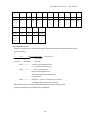
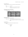
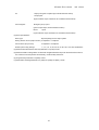
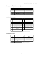
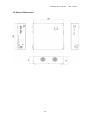
SC12201-K10-10002A
User’s Manual
Two-axis Stage Controller
SHOT-702
1
2nd edition
SC12201-K10-10002A
2nd edition
Notes regarding these materials
・ These materials are intended as a reference to assist our customers in the use of
the SIGMAKOKI CO., LTD. Product best suited to the customer’s application; they
do not convey any license under any intellectual property rights, or any other rights,
belonging to SIGMAKOKI CO., LTD. or a third party.
・ SIGMAKOKI CO., LTD. assumes no responsibility for any damage, or infringement
of any third-party’s rights, originating in the use of any product data, diagram, charts,
programs, or algorithms contained in these materials.
・ All information contained in these materials, including product data, diagrams,
charts, programs and algorithms represents information on products at the time of
publication of these materials, and are subject to change by SIGMAKOKI CO.,LTD.
without notice due to product improvements or other reasons.
・ When using any or all of the information contained in these materials, including
product data, diagrams, charts, programs, and algorithm, please be sure to evaluate
all information and products. SIGMAKOKI CO., LTD. assumes no responsibility for
any damage, liability or other loss resulting from the information contained herein.
・ SIGMAKOKI CO., LTD. products are not designed or manufactured for use in
equipment or system that is used under circumstances in which human life is
potentially at stake. SIGMAKOKI CO., LTD. products cannot be used for any
specific purposes, such as apparatus or systems for transportation, vehicular,
medical, aerospace, nuclear, or undersea repeater use.
・ The prior written approval of SIGMAKOKI CO., LTD. is necessary to reprint or
reproduce in whole or in part these materials.
・ If these products or technologies are subject to the Japanese export control
restrictions, they must be exported under a license Japanese government and
cannot be imported into a country other than the approved destination.
Any diversion or re-export contrary to the export control laws and regulations of
Japan and/ or the country of destination is prohibited.
2
SC12201-K10-10002A
2nd edition
Contents
For Your Safety ........................................................................................................... 4
Chapter 1: Before You Begin .............................................................................. 6
1.Package Contents..................................................................................................... 6
2. Overview.................................................................................................................... 6
3. The SHOT-702 System .......................................................................................... 7
4. Parts of the SHOT-702........................................................................................... 7
Chapter 2: Basic Operations ............................................................................... 9
5.SHOT-702 Connection procedure ........................................................................ 9
6.SHOT-702 Setting.................................................................................................. 10
Chapter 3: Using SHOT-702 to position Motorized Stages ............. 17
7.Using Computer to position Motorized Stages ............................................... 17
8.Using I/O signal ...................................................................................................... 24
9. Using peripheral device to Position Motorized Stages ............................... 25
Chapter 4 : Specification ..................................................................................... 26
10. Specification ......................................................................................................... 26
11. Connector Pin Numbers and Signals ............................................................ 28
12. Exterior Dimensions .......................................................................................... 30
3
SC12201-K10-10002A
2nd edition
For Your Safety
Before using this product, read this manual and all warnings or cautions in the documentation provided.
Only Factory Authorized Personnel should be changes and/or adjust the parts of controller.
The Symbols Used in This Manual
!
WARNING
!
CAUTION
This symbol marks warnings that should be read
This symbol indicates where caution should be used
and used to prevent serious injury or death.
to avoid possible injury to yourself or others, or
damage to property.
The above indications are used together with the following symbols to indicate the exact nature of the
warning or caution.
Examples of Symbols Accompanying Warnings and Cautions
△Symbols enclosed in a triangle indicate warnings and cautions. The exact nature of
the warning or caution is indicated by the symbol inside (the symbol at left indicates
risk of electrocution).
○Symbols enclosed in a circle mark indicate prohibitions(actions that must not be
performed).The exact nature of the prohibition is indicates by the symbol inside or
next to the circle mark (the symbol at left indicates that the product must not be
disassembled).
●Symbols inside a black circle mark actions that must be performed to ensure safety.
The exact nature of the action that must be performed is indicated by the symbol
inside (the symbol at left is used in cases in which the AC adapter must be unplugged
to ensure safety).
Symbols on the product
The symbol mark on the product calls your attention. Please refer to the manual, in the case that you
operate the part of the symbol mark on the product.
!
This symbol labeled on the portion calls your attention.
4
SC12201-K10-10002A
2nd edition
Disclaimer of Liability
①
SIGMAKOKI CO., LTD. does not accept liability for damages resulting from the use of this product or
the inability to use this product.
②
SIGMAKOKI CO., LTD. does not accept liability for damages resulting from the use of this product that
deviates from that described in the manual.
③
SIGMAKOKI CO., LTD. does not accept liability for damages resulting from the use of this product in
extraordinary conditions, including fire, earthquakes, and other acts of God, action by any third party,
other accidents, and deliberate or accidental misuse.
④
If the equipment is used in a manner not specified by the SIGMAKOKI CO., LTD., the protection
provided by the equipment may be impaired.
!
WARNING
● Do not use this product in the presence of flammable gas, explosives, or corrosive substances, in areas
exposed to high levels of moisture or humidity, in poorly ventilated areas, or near flammable materials.
● Do not connect or check the product while the power is on.
● Installation and connection should be performed only by a qualified technician.
● Do not bend, pull, damage, or modify the power or connecting cables.
● Do not touch the products internal parts.
● Connect the earth terminal to ground.
● Should the product overheat, or should you notice an unusual smell, heat, or unusual noises coming from
the product, turn off the power immediately.
● Do not turn on the power in the event that it has received a strong physical shock as the result of a fall or
other accident.
● Do not touch the stage while operation.
● Use dry clothes only for cleaning the equipment.
5
SC12201-K10-10002A
2nd edition
Chapter 1: Before You Begin
1.Package Contents
Purchasers of the Stage Controller should find that the package contains the items listed below. Check
the package contents using the following checklist. Contact your retailer as soon as possible in the event
that you should find that any item is missing or damaged.
□SHOT-702 Stage Controller
:1
□User’s Manual (This Manual)
:1
□AC Power Cable
:1
About the setting of the Memory Switch of this controller, you can set it by sample software.
You can download sample programs from our web page.
For the details of the samples, see the manual of each program.
View our home page
http://www.sigma-koki.com/
2. Overview
This controller is two axes stage controller, which has drivers for five-phase stepping motor.
Because this controller has a microstep driver built-in, the smooth movement in high resolving power is
possible.
When the SHOT-702 is connected to an ordinary personal computer via an RS232C interface, the
stage can be accurately moved to the desired position by simple commands sent from the PC.
In addition, manual operation is possible facility by connecting JOYSTICK (an optional product).
6
SC12201-K10-10002A
2nd edition
3. The SHOT-702 System
4. Parts of the SHOT-702
SHOT-702 Front Panel
③ Stage driving connector
④ Stage driving connector
(first axis)
(second axis)
②POWER LED
①Power switch
SHOT-702 Rear Panel
⑧AC connector
⑦RS232C connector
⑥connector for joy stick
7
⑤I/O connector
SC12201-K10-10002A
2nd edition
Functions:
①Power switch
:The product is on when the switch is set to ON. Set the switch to
OFF to turn the product off.
②POWER LED
: Lights up when powered.
③,④Stage driving connector
:Connect to the motorized stage of your choice. Supports up to
two axes.
⑤I/O connector
: The connector accepts a cable for sending and receiving I/O
and control signals to form an external device. It can also be
used to drive motorized stages remotely or to start programmed
operations.
⑥Connector for joy stick
: This connector is used to connect JS-300 or JB-400 or JD-100.
⑦RS232C connector
:This connector is used when the device is controlled from the
computer via an RS232C interface.
⑧AC connector
: This is where you connect the supplied 2.3meter power cable.
● USABLE DETACHABLE POWER CORDS
Type
Connecter
Cord
Attachment plug cap
AC100-120V
Use the detachable power cord set attached to the product only.
AC200-240V
IEC C-22
Type SJT, No16 AWG Min.
NEMA6-15P
Rated 7A, 250V
3-Conductors
Tandem blade
UL, CSA Approved
(Single phased;2-current carrying &
Rated 7A,250V
ground)
UL, CSA Approved
UL, CSA Approved
Cable length of above Power Supply cord shall be shorter than 4.5m.
8
SC12201-K10-10002A
2nd edition
Chapter 2: Basic Operations
5.SHOT-702 Connection procedure
5-1.Connecting to Motorized Stages
First, connect SHOT-702 to the motorized stages.
②
Please confirm the power switch of the SHOT-702 is turning off.
② Connect a standard cable (D15RP-CA/D15D15A-CA/DMINIS-CA/DBCS-15/DMINIH-CA) to the
connector of the motorized stage.
③Connect the stage to be controlled as the first axis to the STAGE1 connector of the SHOT-702
controller. Also connect the stage controlled as the second axis to the STAGE2 connector.
5-2.Connecting to PC and peripheral device
Connect SHOT-702 to PC and peripherals (JS-300/JB-400/JD-100).
RS232C interface is used for the connection between the PC and SHOT-702.
The RS232C interface communication parameter of the SHOT-702 is described below. Please set the
configurations of the PC side according to the following table.
Parameter
Descriptions
Baud rate
38400bps
Delimiters
CR+LF
Parity
None
Data bits
8bit
Stop bit
1bit
Flow control
Hardware (RTS/CTS) or none (Default value is Hardware)
①Please confirm the power switch of the SHOT-702 is turning off.
②Use a genuine cable RS232C/STR, or 9-pin, D-SUB straight cable with male/female ends using
inch screw threads.
③Insert the male connector of communications cable in to the RS232C connector on the SHOT-702.
Insert the female end into the serial port on your PC.
Please connect peripheral device according to the procedure from ④ to ⑥ if you use it.
④Please use a special cable MDR14-CA for the connection of peripheral device.
⑤The one side of MDR14-CA is connected with the connector of the peripheral device.
⑥The connector on the other side of MDR14-CA is connected with the JOYSTICK connector of
SHOT-702.
5-3.Connecting Power Cable
Connect the supplied power cable to the AC connector on the rear panel of SHOT-702 to plug the
cable into an outlet. (Ensure that it is grounded.)
9
SC12201-K10-10002A
2nd edition
6.SHOT-702 Setting
Adjust the drive (RUN/STOP) current and memory switch of controller for each of the connected
motorized stages.
6-1.Setting the drive current
Set current values supplied from SHOT-702 to stages. Turn a RUN current volume, provided on the top
of the unit, to adjust RUN current corresponding to the stages to use. Use a STOP current volume to set a
ratio to RUN current according to your conditions for the case where the current down function works.
You can make each current adjustment for first axis or second axis independently.
Note that for the STOP current, adjustment is available not for current values, but for a ratio (%) to the
RUN current.
Note: Generally the ratio of the STOP current to the RUN current is approx. 50%.
SHOT-702 Top view
Current volumes
Volume (Expansion)
RUN current setting (Factory-set to 0.75)
Volume No.
0
1
2
3
4
5
6
Run current [A/phase]
0
0.17
0.35
0.66
0.75
0.9
1.1
STOP current settings (Factory-set to 50%)
Volume No.
0
1
2
3
4
5
6
Stop current (%)
0
10
21
35
50
60
68
6-2. Setting Memory Switch
SHOT-702’s various settings are set with Memory Switch.
The setting change of Memory Switch is set with the sample software (SGSample/ SGCommander).
Please download SGSample/SGCommander from homepage (http://www.sigma-koki.com).
10
SC12201-K10-10002A
2nd edition
6-3.Memory Switch List
The memory switch has 44 setting items in all. Please set a necessary item.
No
Memory switch setting
Range/ options
Default value
1
Speed SEL
1~4
1
2
Speed 1(S)
1~500000
100
3
Speed 1(F)
1~500000
1000
4
Speed 1(R)
1~1000
200
5
Speed 2(S)
1~500000
500
6
Speed 2(F)
1~500000
5000
7
Speed 2(R)
1~1000
200
8
Speed 3(S)
1~500000
750
9
Speed 3(F)
1~500000
7500
10
Speed 3(R)
1~1000
200
11
Speed 4(S)
1~500000
1000
12
Speed 4(F)
1~500000
10000
13
Speed 4(R)
1~1000
200
14
COMM/ACK
MAIN/SUB
MAIN
15
Stage1 Unit
PULSE/MICRO/DEG
PULSE
16
Stage2 Unit
PULSE/MICRO/DEG
PULSE
17
Divide1
1/2/4/5/8/10/20/25/40/50/80/100/125/200/250
2
18
Divide2
1/2/4/5/8/10/20/25/40/50/80/100/125/200/250
2
19
Base Rate1
1~1000
20
20
Base Rate2
1~1000
20
21
L sensor Level1
Normal Open/Normal Close
NM CLOSE
22
L sensor Level2
Normal Open/Normal Close
NM CLOSE
23
O sensor Level1
Normal Open/Normal Close
NM OPEN
24
O sensor Level2
Normal Open/Normal Close
NM OPEN
25
N sensor Level1
Normal Open/Normal Close
NM OPEN
26
N sensor Level2
Normal Open/Normal Close
NM OPEN
27
Move1
POS/NEG
POS
28
Move2
POS/NEG
POS
29
ORG1 SEL
MINI/MARK/NORM/CENTER/OFF
MINI
30
ORG2 SEL
MINI/MARK/NORM/CENTER/OFF
MINI
31
ORG1 Speed(S)
1~500000
500
32
ORG1 Speed(F)
1~500000
5000
33
ORG1 Speed(R)
1~1000
200
11
SC12201-K10-10002A
2nd edition
34
ORG2 Speed(S)
1~500000
500
35
ORG2 Speed(F)
1~500000
5000
36
ORG2 Speed(R)
1~1000
200
37
ORG1 Pulse2
0~32000
0
38
ORG2 Pulse2
0~32000
0
39
Acceleration1
Linear/S Curve
S Curve
40
Acceleration2
Linear/S Curve
S Curve
41
EMG Excitation1
On/Off
On
42
EMG Excitation2
On/Off
On
43
OUT Level
Normal High/Normal Low
NM High
44
Flow Control
On/Off
On
6-4.Memory Switch Settings in Detail
The numbers in each heading indicate the number of the memory switch setting item for the SHOT-702
1) SPEED SEL: Speed selection
Choose the initial speed setting used at power on.
[Options] 1 to 4
2~13) SPEED 1 to 4 (S) (F) (R): Speed settings
Set the travel speed of stage (minimum S, maximum F, and acceleration/deceleration time R)
[Options] S
: 1 to 500000PPS
F
: 1 to 500000PPS
R
: 1 to 1000ms
Note: The minimum speed (S) must be less than or equal to the maximum speed (F).
14) COM/ACK: Choose the communication protocol used when communicating with the computer.
Specify whether the controller will return OK/NG in response to command signals sent from the
computer in HOST (COMPUTER) mode.
[Options] MAIN
SUB
: New system (return OK/NG when using interface)
:Old system (do not return OK/NG when using interface)
15) STAGE1 UNIT: Select the units used for display (first axis)
16) STAGE2 UNIT: Select the units used for display (second axis)
Choose the units used to display position coordinates of peripheral device (JS-300/JB-400).
No need to set the units in case that there is no using of peripheral device (JS-300/JB-400).
[Options] PULSE
: Displays number of pulses
MICRO
: Displays number of micro [μm]
DEG
: Display number of degree [°]
12
SC12201-K10-10002A
2nd edition
17) Divide1: Select number of steps for 1
18) Divide2: Select number of steps for 2
[Options] 1,2,4,5,8,10,20,25,40,50,80,100,125,200,250
Number of steps = Divide = BASE RATE (in 0.1µm steps)/ (10 X travel per pulse (in µm))
19) BASE RATE1: Travel per pulse at the base (full) step for the first axis
20) BASE RATE2: Travel per pulse at the base (full) step for the second axis
Input the travel per pulse at the base (full) step for each axis. (MICRO: in 0.1-µm steps, DEG: in
0.001-degree steps)
[Options] At a setting of PULSE: Disabled
At a setting of MICRO: 1 to 1000 (0.1µm to 100µm)
At a setting of DEG: 1 to 1000 (0.001 degrees to 1 degree)
<Settings example> BASERATE = 40 for a directly motorized stage with screw lead of 2mm
Stage
XYZ linear stage
Screw lead
0.5mm
1mm
2mm
Base step angles
Travel per
pulse at
Rotation stage
6mm
10mm
-
0.72°
1μm
2μm
4μm
12μm
20μm
0.005°
10
20
40
120
200
5
base step
BASE RATE
21) L sensor Level1: Specify the input logic for the first-axis limit sensor
22) L sensor Level2: Specify the input logic for the second-axis limit sensor
Select the conditions (input logic) for the limit sensor for each axis.
[Options]
NORMAL OPEN: Normal open (switches ON from default value of OFF
when limit sensor is detected)
NORMAL CLOSE: Normal close (switches OFF from the default value of
ON when limit sensor is detected)
Motorized stages that support normal closed method: OSMS/ HPS/ HDS/ SGSP/ TSDM /TAMM/
GOHTM series.
23) O sensor Level1: Specify the input logic for the first-axis ORG sensor
24) O sensor Level2: Specify the input logic for the second-axis ORG sensor
Select the conditions (input logic) for the ORG sensor for each axis.
[Options]
NORMAL OPEN: Normal open (switches ON from default value of OFF
when limit sensor is detected)
NORMAL CLOSE: Normal close (switches OFF from the default value of
ON when limit sensor is detected)
Motorized stages that support normal open method: OSMS/HPS/HDS/TAMM/GOHTM series.
13
SC12201-K10-10002A
2nd edition
25) N sensor Level1: Specify the input logic for the first-axis NEAR sensor
26) N sensor Level2: Specify the input logic for the second-axis NEAR sensor
Select the conditions (input logic) for the NEAR sensor for each axis.
[Options]
NORMAL OPEN: Normal open (switches ON from default value of OFF
when limit sensor is detected)
NORMAL CLOSE: Normal close (switches OFF from the default value of
ON when limit sensor is detected)
27) Move1: Direction of travel for first axis
28) Move2: Direction of travel for second axis
Select the + direction for each axis
[Options]
POS: Positive (forward) rotation
NEG: Negative (reverse) rotation
29) ORG1 SEL: Specify method used for return to first axis origin
30) ORG2 SEL: Specify method used for return to second axis origin
[Option]
MINI
:MINI method
MARK
:MARK method
NORMAL :Standard method
CENTER :Median point detection method
OFF
:Not return origin
・MINI method
CW sensor
ORG SPEED(F) CW(-)
CW LS detection
ORG SPEED(F) CCW(+)
Move 1000 pulse
ORG SPEED(S) CW(-)
CW LS detection
ORG SPEED(F) CCW(+)
Move ORG offset pulse
・MARK method
ORG sensor
ORG SPPED(F)
NEAR sensor
CW sensor
CW(-)
CW LS detection
1/10
ORG SPEED(S)
ORG SPEED (S)
CCW(+)
CCW (+)
N sensor detection
O sensor detection
14
SC12201-K10-10002A
2nd edition
・standard method
NEAR sensor
ORG sensor
N sensor detection
ORG SPEED(S)
CW(-)
1/10 ORG SPEED(S)
CW(-)
O sensor detection
・median point detection method
CCW(CW) sensor
CW(CCW) sensor
ORG SPEED(F) CW(-)
CW LS detection
ORG SPEED (S) CCW (+)
ORG SPEED(S) CW(-)
ORG SPEED(F) CCW(+)
ORG SPEED(S) CW(-)
Move 1000 pulse
CW LS detection
CCW LS detection
Move 1000 pulse
ORG SPEED(S) CCW(+)
CCW LS detection
ORG SPEED(F) CW(-)
Move middle of
CW/CCW LS
Middle of LS
31)~
~36) ORG1/2 SPEED (S)(F)(R): Specify speed when returning to origin
Set the travel speed of stage (minimum S, maximum F, and acceleration/deceleration time R)
When returning to the mechanical origin for the stage on each axis.
[Options] S: 1 to 500000PPS
F: 1 to 500000PPS
R: 1 to 1000ms
Note: The minimum speed (S) must be less than or equal to the maximum speed (F).
15
SC12201-K10-10002A
2nd edition
37) ORG1 Pulse2: Set ORG offset of the first axis when MINI method set
38) ORG2 Pulse2: Set ORG offset of the second axis when MINI method set
Set the travel (number of pulses) of ORG offset of each axis when MINI method set.
Default value is 0.
[Option]
Division × 500 pulse move
0 to 32000 (unit:1=100pulse)
39) Acceleration1: Set the speed-acceleration profile of the first axis
40) Acceleration2: Set the speed-acceleration profile of the first axis
[Options] Linear
S Curve
:trapezoidal control
:S curve control
41) EMG Excitation1: Set the excitation ON/OFF of the first axis when the emergency stop
42) EMG Excitation2: Set the excitation ON/OFF of the second axis when the emergency stop
[Options] ON
OFF
:Excitation
:Free motor
43) TRG Level: Logical settings for trigger output
Set the output signal level of I/O function.
[Option]
Normal High: When outputting signal, it becomes LOW.
Normal Low: When outputting signal, it becomes HI.
44) Flow Control: Flow control selection
Specify whether the controller will do flow control in RS232C communication.
[Option]
ON: Hardware (RTS/CTS)
OFF: None
16
SC12201-K10-10002A
2nd edition
Chapter 3: Using SHOT-702 to position Motorized Stages
7.Using Computer to position Motorized Stages
The controller can be connected to a computer using an RS232C interface. Motorized stages can then
be precisely controlled by commands (strings) transmitted from the computer.
7-1. List of Commands
The following is a list of available commands:
Command
String
Details
Return to mechanical origin
H:
Detect mechanical origin
Set number of pulses for
M:
Axis of movement, direction, number of
relative movement
Set number of pulses for
pulses
A:
Absolute coordinates
Jog command
J:
Move at minimum speed (S)
Drive command
G:
Start
Stop command
L:
Stop
Set electronic (logical) origin
R:
Set the electronic (logical) origin to the
absolute movement
current position
Speed settings
D:
Set S, F and R
ORG speed setting
V:
Set S, F and R of ORG
Free motor
C:
Excitation ON/OFF
Switch number of steps
S:
Switch number of steps
Status1
Q:
Return current position etc.
Status2
!:
Return B(busy)/R(ready)
Internal information
?:
Check internal information
Output
O:
Output to I/O connector
Input
I:
Input from I/O connector
17
SC12201-K10-10002A
2nd edition
7-2. Command Format
The communications protocol used between the controller and the computer depends on the memory
switch COMM/ACK.
1. When COMM/ACK is set to MAIN (new system):
A protocol is used in which one response is issued for each command.
Command string ………… receive
Response string ………… sent
The response string when a command is received normally is “OK,’’ that when the command was not
received, “NG.’’ In some cases, for example in response to confirmation commands, data will be
returned instead of “OK.’’ Commands should only be sent after checking the internal status of the
controller.
2. When COMM/ACK is set to SUB (old system):
A protocol is used in which the controller does not respond to each command. Data will however be
returned in response to some commands, such as confirmation commands.
To determine whether or not a command was received normally, use the Q command to check status.
7-3.Commamd in Detail
(1) H command: Return to mechanical origin
Features: This command is used to detect the mechanical origin for a stage and set that position as the
origin. Once the mechanical origin has been detected, the value displayed will be 0. The stage will move
at the speed specified in the ORG1 (2) SPEED (S, F, R) memory switches.
H: 1
Detect the mechanical origin for the first axis.
H: 2
Detect the mechanical origin for the second axis.
H: W
Detect the mechanical origin for the first and second axes.
(2) M command: Set number of pulses for relative travel
Features: This command is to specify the axis of travel, direction, and the travel (number of pulses).
This command must always be followed by a drive (G) command. Travel is by means of
acceleration/deceleration driving. The distance traveled is specified in pulses.
M: 1+P1000
Travel 1000 pulses in the + direction on the first axis
G:
M: 2- P 10000
Travel 10000 pulses in the - direction on the second axis
G:
M: W+P500-P200 Travel 500 pulses in the + direction on the first axis and 200 pulses in the G:
direction on the second axis
18
SC12201-K10-10002A
2nd edition
(3) A command: Set number of pulses for absolute travel
Features: This command is to specify the axis of travel, direction, and the travel (number of pulses).
This command must always be followed by a drive (G) command. Travel is by means of
acceleration/deceleration driving.
The distance traveled is specified in the number of pulses depending on the control method. This
command also returns the axis to the electrical (logical) origin.
A: 1-P2000
Travel to the 2000 pulse position in the - direction on the first axis.
G:
A: 2+P30000
Travel to the 30000 pulse position in the + direction on the second axis.
G:
A: W+P1000-P2000
G:
Travel to the 1000 pulse position in the + direction on the first axis and
the 2000 pulse position in the - direction on the second axis
(4) J command: JOG
Features: This command drives stages continuously (at a constant speed) at the starting speed (S).
This command must always be followed by a drive (G) command.
J:1+
move in the + direction on the first axis.
G:
J:2-
move in the - direction on the second axis.
G:
J:W-+
move in the - direction on the first axis and in the + direction on the second axis
G:
(5) G command: Drive
Features: When a drive command is issued, the stage starts moving, moves the specified number of
pulses, and then stops. The G command is used after M, A, and J commands.
G:
Drive
G
Drive
(6) L command: Decelerate and stop
Features: When this command is executed, the stage decelerates and stops.
L:1
First axis decelerates and stops
L:2
Second axis decelerates and stops
L:W
First- and second-axis decelerate and stop
19
SC12201-K10-10002A
2nd edition
(7) L: E command: Emergency stop
Features: This command stops all stages immediately, whatever the conditions.
L:E
Stop first and second axes immediately
(8) R command: Set electronic (logical) origin
Features: This command is used to set electronic (logical) origin to the current position of each axis.
R:1
Set the electronic (logical) origin for the first axis
R:2
Set the electronic (logical) origin for the second axis
R:W
Set the electronic (logical) origins for the first- and second-axis
(9) D command: Speed settings
Features: The minimum speed (S), maximum speed (F), and acceleration/deceleration time (R) are set
according to the SPEED SEL memory switches when the power is turned on. This command allows you
to change these initial settings.
The following options are available:
Minimum speed(S)
1~500000PPS
Maximum speed (F)
1~500000PPS
Acceleration/deceleration time (R)
1~1000mS
Note that the minimum speed (S) must be less than or equal to the maximum speed (F).
D:1S100F1000R50
Adjust speed settings for the first axis (S=100PPS/F=1000PPS/
R=50ms)
D:2S1000F5000R200
Adjust speed settings for the second axis (S=1000PPS/F=5000PPS/
R=200ms)
D:WS100F1000R200S100F1000R200
First-axis speed settings
Adjust speed settings for the first- and second-axis
Second-axis speed settings
20
SC12201-K10-10002A
2nd edition
(10) V command: ORG speed settings
Features: ORG speed (minimum speed (S), maximum speed (F), and acceleration/deceleration time (R))
is set according to the SPEED SEL memory switches when the power is turned on. This command allows
you to change these initial settings.
The following options are available:
Minimum speed(S)
1~500000PPS
Maximum speed (F)
1~500000PPS
Acceleration/deceleration time (R)
1~1000mS
Note that the minimum speed (S) must be less than or equal to the maximum speed (F).
V:1S100F1000R50
Adjust ORG speed settings for the first axis (S=100PPS/F=1000PPS/
R=50ms)
V:2S1000F5000R200
Adjust ORG speed settings for the second axis (S=1000PPS/F=5000PPS
/R=200ms)
V:WS100F1000R200S100F1000R200
First-axis speed settings
Adjust speed settings for the first- and second-axis
Second-axis speed settings
(11) C command: Free/ hold motor (Excitation ON/OFF)
Features: This command is used to excite the motor or to turn excitation off, making it possible to move
(rotate) stages manually.
The options available are 0: free motor, and 1: excitation (hold motor).
C:10
Free first-axis motor
C:21
Excite (hold) second-axis motor
C:W1
Excite (hold) both the first- and second-axis motors
(12) S command: Changing the number of steps
Features: Use this command to change motor step angle (number of steps). Select one of the following
15 step angles built into the driver. First specify an axis, then set the value.
S: 180 Divides the step angle of the first axis into 80 angles.
S: 280 Divides the step angle of the second axis into 80 angles.
If the base step (full step) angle is to 0.72 degrees, the stepping motor makes one full turn every 500
pulses. The motor is said to have a minimum resolution of 0.72 degrees (if the motor moves 10 mm for
each turn, minimum resolution=10 mm ÷ 500 pulses=20μm). You can change the minimum resolution
by dividing the motor step angle (1/2=0.36°).
21
SC12201-K10-10002A
Number of
2nd edition
1
2
4
5
8
10
20
25
40
50
80
Step angle
0.72°
0.36°
0.18°
0.144°
0.09°
0.072°
0.036°
0.0288°
0.018°
0.0144°
0.009°
Number of
500
1000
2000
2500
4000
5000
10000
12500
20000
25000
40000
100
125
200
250
Step angle
0.0072°
0.00576°
0.0036°
0.00288°
Number of
50000
62500
100000
125000
steps
pulses per
full turn
Number of
steps
pulses per
full turn
(13) Q command: Status 1
Features: On receipt of this command, the controller returns the coordinates for each axis and the current
state of each stage.
Q:
-
100,-
200,ACK1,ACK2,ACK3 …… Data returned
First-axis
Second-axis
Three-character
coordinates
coordinates
string data
ACK1 ・・・・・・・・・
X:Command or parameter errors.
K :Command received normally.
ACK2 ・・・・・・・・・
L :First axis stopped at LS
M:Second axis stopped at LS
W:First and second axes stopped at LS
K :Normal stop
ACK3 ・・・・・・・・・
B:(BUSY) L, Q ,and ! commands can be received
R:(READY) all commands can be received
※Coordinate values for each axis have a fixed length of ten digits, including symbols
(Symbols are left-aligned, coordinates values right-aligned).
22
SC12201-K10-10002A
2nd edition
(14) ! command: Status 2
Features: On receipt of this command, the controller returns the stage operating status.
!:
ACK3 ・・・・・・・・・
Data returned
ACK3 ・・・・・・・・・
B:(BUSY) L, Q, ! , and P commands can be received
R:(READY) all commands can be received
(15) ? command: Request for internal information
Features: This command returns controller settings.
?: [Parameter] [AXIS]
Parameter
Data returned
Examples
V
Version numbers
V1.00
P
Travel per pulse
1.00,1.00
S
Division
2,2
D
Travel speed
S100F1000R200
B
ORG speed
S500F5000R200
(16) O command: Output
Features: This command changes the output status.
[Option]
O:0
Set the output signal to Normal level (Default value: High)
O:1
Output signal (Default value: Signal will be Low level when outputting
signal )
(17) I command: input
Features: This command checks the input status. Signal level is active low.
[Option]
I:
0 or 1 …Data returned
0: negative
1: active
23
SC12201-K10-10002A
2nd edition
8.Using I/O signal
SHOT-702 has following I/O signal functions.
Output-1 point
Emergency stop input-1 point
Busy signal output-1 point
Input-1 point (photo-coupler input)
①Output
This is output port. Output signal can be controlled by O command.
Output logic is switchable by memory switch. Default value is normal HI.
②Busy signal output
Outputting signal when motorized stages moving.
Busy signal level is switchable by memory switch. Default value is normal HI.
③Input
This is input port. Input signal can be checked by I command.
Input logic is active low.
④EMG STOP input
EMG STOP is photo-coupler input (8-2).
EMG STOP turns on when the current passes in TLP281 by EMG STOP terminal being connected to
ground. PC or peripheral device can't move Motorized stages when EMG STOP signal turns on.
If EMG STOP signal turn off, motorized stages can move again. However, controller is necessary to
turn on the power supply again because it enters the state that cannot be operated due to the
communication fault when there are communication statements from PC while EMG STOP turns on.
8-1 OUT/BUSY_OUT circuit
8-2 IN/EMG_STOP circuit
24
SC12201-K10-10002A
2nd edition
9. Using peripheral device to Position Motorized Stages
The controller can be connected to a peripheral device (JS-300/JB-400/JD-100). Motorized stages can
then be manual controlled and displayed the position coordinates for each axis by peripheral device.
For the details, see the User’s manual of peripheral device (JS-300/JB-400/JD-100).
25
SC12201-K10-10002A
2nd edition
Chapter 4 : Specification
10. Specification
1) General specifications
Power source
AC 100-240V
Consumption
70VA
Operating temperature
5 to 40℃
Storage temperature
-20 to 60℃
Altitude
up to 2000m
50/60Hz
Indoor use only
Installation category
Ⅱ
Pollution degree
2
Ambient humidity
20 to 80%RH (no condensation)
External dimensions
260W x280D x70H (excluding projections)
Weight
2.8 kg
(2) Performance
Controlling axis
2 axis
Maximum driving speed (F) 1 to 500kPPS
Minimum driving speed (S)
1 to 500kPPS
Acceleration/deceleration time (R)
Sensor input
1 to 1000ms
Origin sensor/proximity sensor/CW (-) limit/CCW (+) limit
(Memory switches can be used to change input logic for sensors.)
Method of return to origin
MINI method/MARK method/Standard method
Median point detection method/Not return origin
(You can change method of ORG by Memory Switch)
Interface
RS232C interface
Communication Parameters
- Baud rate 38400
- Data bits 8 bits
- Parity None
- Stop bit 1 bit
- Flow control Hardware
- Delimiters CR+LF
26
SC12201-K10-10002A
I/O
2nd edition
1 input point (photo-coupler input, internal resistance 390Ω)
1 output point
(Open-collector output, maximum use conditions DC24V 50mA)
Control signals
Emergency stop-1 point
(photo-coupler input, internal resistance 390Ω)
BUSY
1 point
(Open-collector output, maximum use conditions DC24V 50mA)
(3) Driver Specifications
Driver type
Bi-polar pentagon micro-steps system
Driving electric current (output current) 0.1A/phase to 1.1A/phase
Current down (stop current)
0.1A/phase to 0.7A/phase
Division (micro-step) settings
1, 2, 4, 5, 8, 10, 20, 25, 40, 50, 80, 100, 125, 200, 250 divisions
(4) Electrical fast transmit/burst immunity EN61000-4-4 (2004) Level2
(5) Electrical isolation voltage When AC1kV 60Hz is applied between the power terminal and the case for
one minute at room temperature and humidity, no abnormality shall occur.
(6) Surge immunity EN61000-4-5 (2006) Level2
(7) Electrostatic discharge EN61000-4-2 (1995)+A1 (1998)+A2 (2001) Level2.
27
SC12201-K10-10002A
11. Connector Pin Numbers and Signals
11-1.I/O Connector Signals
No.
Name
No.
Name
1
OUT
5
-
2
Busy
6
GND
3
IN
7
+5V
4
EMG STOP
8
-
HR212-10RA-8SDL (72) (HIROSE products) used
11-2. STAGE1,2 Connector
No.
Name
No.
Name
1
Blue: motor wiring
9
-
2
Red: motor wiring
10
-
3
Orange: motor wiring
11
LS (+): limit detection on +
4
Green: motor wiring
12
LS (-): limit detection on-
5
Black: motor wiring
13
GND: common sensor
6
GND: common sensor
14
NEAR: proximity detection
7
ORG: mechanical origin
15
+24V: sensor power supply
detection
8
+24V: sensor power supply
Female XM2F-1510 connector (OMRON products) used
11-3. RS232C Connector
No.
Name
No.
Name
1
-
6
DTR
2
TxD
7
CTS
3
RxD
8
RTS
4
DSR
9
-
5
SG
XM3B-0922-132 connector (OMRON products) used
28
2nd edition
SC12201-K10-10002A
11-4. JOYSTICK Connector
No.
Name
No.
Name
1
GND
9
+5V
2
+5V
10
RXD-
3
RXD+
11
TXD-
4
TXD+
12
CONNECT
5
STOP
13
-
6
-
14
-
7
-
8
GND
10214-52A2PL (Sumitomo 3M products) used
29
2nd edition
SC12201-K10-10002A
12. Exterior Dimensions
30
2nd edition
SC12201-K10-10002A
2nd edition
SIGMAKOKI CO., LTD.
Tokyo Head Office
SIGMAKOKI Tokyo Head office 19-9, Midori 1 chome, Sumida-ku, Tokyo 130-0021, JAPAN
Tel:+81-3-5638-8228 Fax:+81-3-5638-6550 e-mail: [email protected]
Technology center 1-1 Yatsukaho, Hakusan-shi, Ishikawa, 924-0838, Japan
31