1
Model 3502
Optical Chopper
User’s Manual
1
Declaration of Conformity
We declare that the accompanying product, identified with the
mark, complies with
requirements of the Electromagnetic Compatibility Directive, 2004/108/EC and the Low Voltage
Directive 2006/95/EC.
Model Number: 3502
Year mark affixed: 2014
Type of Equipment:
Electrical equipment for measurement, control, and laboratory use in industrial locations.
Manufacturer:
Newport Corporation
1791 Deere Avenue
Irvine, CA 92606
Standards Applied:
Compliance was demonstrated to the following standards to the extent applicable:
BS EN61326-1: 2006 “Electrical equipment for measurement, control and laboratory use
– EMC requirements”.
BS EN 61010-1:2010, “Safety requirements for electrical equipment for measurement,
control and laboratory use”.
Malcolm Minty
Site General Manager, New Focus
Newport Corporation
1791 Deere Ave, Irvine, CA92606 USA
2
Warranty
New Focus warrants that this product will be free from defects in material and workmanship and
will comply with New Focus’s published specifications at the time of sale for a period of one
year from the date of shipment. If found to be defective during the warranty period, we will
either repair or replace the product at our discretion.
To exercise this warranty, write or call your local New Focus office or representative, or contact
Newport headquarters in Irvine, California. You will be promptly assisted and given return
instructions. Send the product, freight prepaid, to the indicated service facility. We will make
repairs and return the instrument, freight prepaid. Repaired products are warranted for the
remainder of the original warranty period or 90 days, whichever first occurs.
Limitation of Warranty
The above warranties do not apply to products which have been repaired or modified without
New Focus’s written approval, or products subjected to unusual physical, thermal or electrical
stress; improper installation; misuse; abuse; accident or negligence in use, storage, transportation
or handling. This warranty also does not apply to fuses, batteries, or damage from battery
leakage.
This warranty is in lieu of all other warranties, expressed or implied, including any implied
warranty of merchantability or fitness for a particular use. New Focus shall not be liable for any
indirect, special, or consequential damages resulting from the purchase or use of its products.
First printing 2014
© 2014 by New Focus, Santa Clara, CA. All rights reserved. No part of this manual may be
reproduced or copied without the prior written approval of New Focus.
This manual has been provided for information only and product specifications are subject to
change without notice. Any changes will be reflected in future printings.
New Focus
3635 Peterson Way
Santa Clara, CA, 95054
USA
Part No. 90068136 Rev A
3
Confidentiality & Proprietary Rights
Reservation of Title
The New Focus Programs and all materials furnished or produced in connection with them
("Related Materials") contain trade secrets of New Focus and are for use only in the manner
expressly permitted. New Focus claims and reserves all rights and benefits afforded under law in
the Programs provided by New Focus.
New Focus shall retain full ownership of Intellectual Property Rights in and to all development,
process, align or assembly technologies developed and other derivative work that may be
developed by New Focus. Customer shall not challenge, or cause any third party to challenge
the rights of New Focus.
Preservation of Secrecy and Confidentiality and Restrictions to Access
Customer shall protect the New Focus Programs and Related Materials as trade secrets of New
Focus, and shall devote its best efforts to ensure that all its personnel protect the New Focus
Programs as trade secrets of New Focus. Customer shall not at any time disclose New Focus's
trade secrets to any other person, firm, organization, or employee that does not need (consistent
with Customer's right of use hereunder) to obtain access to the New Focus Programs and Related
Materials. These restrictions shall not apply to information (1) generally known to the public or
obtainable from public sources; (2) readily apparent from the keyboard operations, visual
display, or output reports of the Programs; (3) previously in the possession of Customer or
subsequently developed or acquired without reliance on the New Focus Programs; or (4)
approved by New Focus for release without restriction.
Trademarks
The New Focus logo and name are registered trademarks of Newport Corporation in Mexico,
Israel, Singapore, the European Union, Taiwan, Hong Kong, China, Japan, Korea, Canada,
Australia, and the United States.
4
Contents
Declaration of Conformity ............................................................................................ 1
Warranty ....................................................................................................................... 2
Limitation of Warranty ................................................................................................. 2
Confidentiality & Proprietary Rights ............................................................................ 3
Contents ........................................................................................................................ 4
Figures........................................................................................................................... 7
1
Safety Precautions
1.1
1.2
1.3
Definitions and Symbols ..................................................................................... 8
1.1.1
General Warning or Caution ....................................................................... 8
1.1.2
Electrical Shock .......................................................................................... 8
1.1.3
European Union CE Mark .......................................................................... 9
1.1.4
On................................................................................................................ 9
1.1.5
Off ............................................................................................................... 9
1.1.6
Waste Electrical and Electronic Equipment (WEEE) ................................. 9
1.1.7
Control of Hazardous Substances ............................................................. 10
Warnings and Cautions ..................................................................................... 10
1.2.1
General Warnings ..................................................................................... 10
1.2.2
General Cautions ....................................................................................... 10
Location of Labels and Warnings ..................................................................... 12
1.3.1
2
Model 3502 Optical Chopper Controller Rear Panel ................................ 12
General Information
2.1
8
13
System Overview .............................................................................................. 13
2.1.1
Key Product Features: ............................................................................... 13
2.2
Scope of this Manual ........................................................................................ 13
2.3
Unpacking and Inspection ................................................................................ 14
2.3.1
2.4
What is included ....................................................................................... 14
Environmental Operation Requirement ............................................................ 15
2.4.1
Operating Limits ....................................................................................... 15
2.4.2
Weight and Dimensions ............................................................................ 15
5
3
Using the Chopper
3.1
How the Model 3502 Optical Chopper Works ................................................. 16
3.2
Mounting the Unit ............................................................................................. 17
3.2.1
Chopper Head ........................................................................................... 17
3.2.2
Chopper Motor .......................................................................................... 19
3.2.3
Mounting a Wheel..................................................................................... 19
3.2.4
Mounting the Wheel Cover ....................................................................... 21
3.3
Rack Mount Option .......................................................................................... 22
3.4
Initial Setup ....................................................................................................... 22
3.5
3.4.1
Power ........................................................................................................ 23
3.4.2
Connecting the Chopper Head to the Chopper Controller ........................ 23
3.4.3
Connecting the Chopper Controller to a Computer via USB ................... 23
Operation .......................................................................................................... 23
3.5.1
3.6
4
6
Front Panel Operation ............................................................................... 24
Back Panel Operation ....................................................................................... 30
Computer Interfacing
32
4.1
Introduction ....................................................................................................... 32
4.2
Using the Graphical User Interface (GUI) ........................................................ 32
4.2.1
5
16
A Quick Start: How to Use the ‘New Focus Chopper Application’ ......... 33
4.3
USB Communication ........................................................................................ 34
4.4
Command Index and Conventions .................................................................... 34
4.5
Command Description ...................................................................................... 36
Troubleshooting
43
5.1
Normal Startup Operation ................................................................................. 43
5.2
Symptoms and Steps to Follow ........................................................................ 43
Specifications
45
6.1
Chopping Frequency ......................................................................................... 45
6.2
Internal Synthesizer .......................................................................................... 45
6.3
Reference Input ................................................................................................. 45
6.4
Reference Output .............................................................................................. 46
6.5
Phase Shifter ..................................................................................................... 46
6
7
6.6
Harmonic Locking ............................................................................................ 46
6.7
External Voltage Control .................................................................................. 46
6.8
General .............................................................................................................. 46
Maintenance and Service
47
7.1
Enclosure Cleaning ........................................................................................... 47
7.2
Technical Support ............................................................................................. 47
7.3
Technical Support Contacts .............................................................................. 47
7.4
Service .............................................................................................................. 48
7.5
Warranty ........................................................................................................... 48
7
Figures
Figure 1: Exclamation symbol. .......................................................................... 8
Figure 2: Electrical Shock symbol. .................................................................... 8
Figure 3: CE mark.............................................................................................. 9
Figure 4: ON symbol. ........................................................................................ 9
Figure 5: OFF symbol. ....................................................................................... 9
Figure 6: WEEE Directive symbol. ................................................................... 9
Figure 7: RoHS Compliant symbol. ................................................................ 10
Figure 8: Warning, Certification, and Information Label. ............................... 12
Figure 9: Functional block diagram for Model 3502 Optical Chopper. .......... 17
Figure 10: Model 3502 Optical Chopper Head with wheel cover installed. ... 18
Figure 11: Dimensions of Model 3502 Optical Chopper Head. ...................... 19
Figure 12: Chopper wheels. ............................................................................. 20
Figure 13:
Rack Mount Kit for Model 3502 Optical Chopper ....................... 22
Figure 14:
Model 3502 Optical Chopper Controller front panel. ................... 24
Figure 15:
Model 3502 Optical Chopper Controller back panel. ................... 30
Figure 16:
Model 3502 Optical Chopper Application window. ..................... 33
8
Safety Precautions
1
1.1
Definitions and Symbols
The following terms and symbols are used in this manual.
1.1.1
General Warning or Caution
Figure 1:
Exclamation symbol.
The Exclamation symbol in the figure above appears in Warning and Caution
tables throughout this manual. This symbol indicates that you should read the
associated documentation to determine the nature of any potential hazards and
any actions that should be taken against these hazards.
1.1.2
Electrical Shock
Figure 2:
Electrical Shock symbol.
The Electrical Shock symbol in the figure above appears throughout this
manual. It indicates a hazard arising from dangerous voltage. Any mishandling
could result in irreparable damage to the equipment, and personal injury or
death.
9
1.1.3
European Union CE Mark
Figure 3:
CE mark.
The presence of the CE Mark on New Focus equipment means that this
instrument has been designed, tested and certified compliant to all applicable
European Union (CE) regulations and recommendations.
1.1.4
On
Figure 4:
ON symbol.
The symbol in the figure above represents a power switch position on the Model
3502 Optical Chopper Controller. This symbol represents a Power On
condition.
1.1.5
Off
Figure 5:
OFF symbol.
The symbol in the figure above represents a power switch position on the Model
3502 Optical Chopper Controller. This symbol represents a Power Off
condition.
1.1.6
Waste Electrical and Electronic Equipment (WEEE)
Figure 6:
WEEE Directive symbol.
This symbol on the product or its packaging indicates that the product must not
be disposed with regular waste. It is the user’s responsibility to dispose of waste
equipment marked with the WEEE Directive Symbol according to local laws.
The separate collection and recycling of WEEE waste at the time of disposal
will help conserve natural resources and ensure that it is recycled or disposed of
10
in a manner that protects human health and the environment. For information
about where the user can drop off WEEE waste for recycling, please contact
your local New Focus representative.
1.1.7
Control of Hazardous Substances
Figure 7:
RoHS Compliant symbol.
This label indicates product compliance with the EU Directive 2002/95/EC that
restricts the content of six particular hazardous substances.
1.2
1.2.1
Warnings and Cautions
General Warnings
Observe these general warnings when operating or servicing this equipment:
1.2.2
Thoroughly read and understand this User’s Manual.
Heed all warnings on the unit and in the operating instructions.
Use this equipment indoors only.
The external input power to this equipment can be up to 240 VAC.
Please follow this User’s Manual for proper use or installation of this
instrument.
Disconnect power before cleaning the equipment. Do not use liquid or
aerosol cleaners; use only a damp lint-free cloth.
Lockout all electrical power sources before servicing the equipment.
There are no user-replaceable fuses in this equipment. The user must
ensure that appropriate current-limiting protection is provided by the
external AC power line.
Do not operate this equipment in an explosive or flammable atmosphere.
Use only the New Focus-supplied mains power cord with the external
AC supply. Use of under-rated power cords may cause property
damage.
General Cautions
Observe these cautions when operating this equipment:
Thoroughly read and understand this User’s Manual.
11
If this equipment is used in a manner not specified in this manual, the
protection provided by this equipment may be impaired.
Do not block ventilation openings.
Use only the specified replacement parts.
Follow precautions for static sensitive devices when handling this
equipment.
This product should only be powered as described in the manual.
There are no user-serviceable parts inside the Model 3502 Optical
Chopper Controller or motor head.
WARNING
If this equipment is used in a manner not specified in this manual, the
protection provided by this equipment may be impaired.
WARNING
This instrument is intended for use by qualified personnel who recognize
thermal, shock, or laser hazards and are familiar with safety precautions
required to avoid possible injury. Read this User’s Manual thoroughly
before attempting to use the Model 3502 Optical Chopper!
CAUTION
The Model 3502 Optical Chopper is designed to be safe when operated
under Normal Environmental Conditions as defined in EN61010-1:2010.
Operation under harsher environmental conditions can result in severe
injury.
The Model 3502 Optical Chopper is intended for use in an industrial
laboratory environment. Use of this product in other environments, such
as residential, may result in electromagnetic compatibility difficulties due
to conducted as well as radiated disturbances.
12
1.3
1.3.1
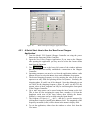
Location of Labels and Warnings
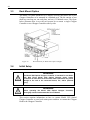
Model 3502 Optical Chopper Controller Rear Panel
Figure 8:
Warning, Certification, and Information Label.
13
General Information
2
2.1
System Overview
The Model 3502 Optical Chopper is used to introduce a periodic interruption of
a light path in an optical experiment resulting in an amplitude modulation,
which is useful for many small optical signal detection schemes. The modulation
frequency can be controlled from 4 Hz to 10.65 kHz. Full control is available
through the Model 3502 Optical Chopper Controller’s front panel. In addition,
the Chopper Controller can be programmed over a USB communication
interface to set and measure the modulation frequency, adjust the interruption
phase, and perform all other operations available through the front panel.
2.1.1
Key Product Features:
A number of advanced features make the Model 3502 Optical Chopper an
excellent choice for many applications:
2.2
Extremely low jitter noise across entire range of chopping frequencies
Windows-based graphical user interface (GUI)
User-written software control
LabVIEWTM and C# examples
Scope of this Manual
Carefully read this User’s Manual before using the 3502 Optical Chopper.
Be especially careful to observe the warnings and cautions throughout this
manual. If any operating instructions are not clear, please contact New Focus.
This instruction manual contains the necessary information for operation and
maintenance of the Model 3502 Optical Chopper, as well as information for
troubleshooting and obtaining service if necessary.
14
2.3
Unpacking and Inspection
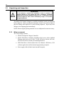
WARNING
Do not attempt to operate this equipment if there is evidence of
shipping damage or you suspect the unit is damaged. Damaged
equipment may present additional hazards to you. Contact New Focus
technical support for advice before attempting to plug in and operate
damaged equipment.
The Model 3502 Optical Chopper is carefully assembled, tested, and inspected
before shipment. Upon receiving this instrument, check for any obvious signs of
physical damage that might have occurred during shipment. Report any such
damage to the shipping agent immediately.
NOTE: Retain original packing materials in case reshipment becomes necessary.
2.3.1
What is included
The 3502 package contents:
Model 3502 Optical Chopper Controller.
Model 3502 Motor Assembly (including wheel cover) with a shielded
Ethernet cable and a set of 2-slot, 7/5-slot, 42/30-slot, 60-slot, 60/2-slot,
and 100-slot wheels, and lab post mounting hardware.
USB Flash Drive which contains this User Manual, USB driver, GUI
software application and documented programming examples.
Power supply cables (North American and European).
15
Environmental Operation Requirement
2.4
2.4.1
Operating Limits
Parameter
Voltage Requirements
Minimum
100V/50-60Hz
Maximum
240V/50-60Hz
25 Watts
100-240 VAC
50-60 Hz
Electrical Ratings
Operating temperature
10 °C (≤ 90% humidity, noncondensing)
40 °C (≤ 90 % humidity,
non-condensing)
Storage temperature
0 °C (≤ 85% humidity, noncondensing)
50 °C (≤ 85 % humidity,
non-condensing)
Relative Humidity (storage)
≤ 85%
Altitude
< 3000 meters (10000 feet)
Environment, Use
Indoor Use Only
Pollution Degree
2
*Operating outside the operating limits may damage the unit.
2.4.2
Weight and Dimensions
Net Weight
5.7 lb. (Chopper Head assembly included)
Controller
Dimensions
4.0 in x 8.5 in x 11.0 in
(H x W x L)
16
Using the Chopper
3
3.1
How the Model 3502 Optical Chopper Works
The Model 3502 Optical Chopper is designed to interrupt light paths in optical
experiments at frequencies from 4 Hz to 10.65 kHz. Both single- and dual-beam
experiments can be performed across a broad range of chopping frequencies.
The Chopper has a crystal-controlled frequency synthesizer that serves as an
internal reference frequency for locking the Chopper to a particular chopping
frequency. Reference frequencies can also be provided through the Sync In BNC
connection to allow the Chopper to lock to an external source.
Several measures ensure that jitter and drift of the chopping frequency is
reduced to a minimum. Precision photo-etched wheels are mounted on a high
quality DC motor. The Model 3502 Optical Chopper Head has a photo-sensor
for monitoring the chopping frequency of the outer part of the wheel. The
Chopper Controller then actively stabilizes the motor speed to match the desired
chopping frequency. This technique minimizes phase noise at the chopping
frequency and provides for long-term stable chopping with minimal frequency
drift.
Figure 9 shows a block diagram of the Model 3502 Optical Chopper system.
Programmable divide/multiply circuitry allows for harmonic or subharmonic
locking of the Chopper to the reference frequency. In addition, the phase of the
chopping frequency may be varied over a -180 to +179 degree range with
respect to the reference frequency. A variety of TTL-level outputs are available
for use in triggering lock-in amplifiers, oscilloscopes, photon counters, or
boxcar averagers.
The chopping frequency, as well as a number of other operating parameters, can
be viewed on the front panel display. Easy-to-use cursor keys provide easy
adjustment of operating parameters. From the front panel the user can store and
recall up to nine instrument setups. A USB 2.0 interface provides remote
operation of all instrument functions.
The Chopper Head can be mounted on a 1/2”-diameter post or bolted directly to
a standard optical bench. The Model 3502 Optical Chopper is supplied with six
Chopper wheels and a wheel cover. The Model 3510 Rack Mount Kit, sold
separately, enables the Chopper Controller to be mounted in a rack.
17
Figure 9:
3.2
3.2.1
Functional block diagram for Model 3502 Optical Chopper.
Mounting the Unit
Chopper Head
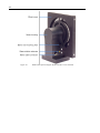
The Model 3502 Optical Chopper Head (Figure 10 and Figure 11) may be
secured to standard optical benches using ¼”-20 or M6 bolts. The bolts pass
through the mounting plate perpendicular to the plane of the optical bench. This
mounting method provides the advantage of allowing the wheel to be rotated by
loosening the ¼”-20 set screws on the side of the motor mount. Do not overtighten the set screws.
The Model 3502 Optical Chopper head may also be mounted on standard ½”
optical bench rods. First, loosen the two ¼”-20 set screws. (These secure the
head to the mounting plate by compressing on the dowel.) Remove the dowel
and mounting plate assembly. Insert the ¼”-20 knob (supplied with the
Chopper) into the base of the head. This knob is inserted into the same hole
occupied by the dowel. Slide the motor mount onto the ½” optical bench rod and
hand- tighten the knob. Do not over-tighten.
18
Figure 10:
Model 3502 Optical Chopper Head with wheel cover installed.
19
Figure 11:
3.2.2
Dimensions of Model 3502 Optical Chopper Head. Dimensions in inches (mm).
Chopper Motor
The operating life of the Chopper motor is limited. Long-term use of the motor
at high speed will result in faster wear and a shorter lifetime. Contact New
Focus for details about replacing the motor, if this becomes necessary.
3.2.3
Mounting a Wheel
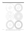
Six wheels are shipped with Model 3502 Optical Chopper, shown in Figure 12
below. To install or change a wheel first power off the Chopper Controller.
Secure the chopping head to a work surface. Remove the four 4-40 screws that
secure the retaining cap over the wheel, while taking care not to bend the wheel
on the optical pickup. Install the replacement wheel, retaining cap, and 4-40
screws. Do not over-tighten the screws. Please note that if a wheel is bent during
the installation/removal process, it can be very difficult to straighten again. This
may degrade the stability of operation of the Model 3502 Optical Chopper
system, and a replacement wheel may be required.
20
Figure 12:
Chopper wheels. Top row: 2-slot and 60/2-slot wheels. Middle row:7/5-slot and 42/30-slot wheels.
Bottom row: 60-slot and 100-slot wheels. All wheels are 4.50” (114.3 mm) O.D.
21
WARNING
The moving wheel may inflict injury. The operator should ensure the
safety of personnel who may be exposed to this hazard.
3.2.4
Mounting the Wheel Cover
WARNING
The wheel cover is provided for safety and its installation is
encouraged. The Chopper wheel can cause injury if it is touched while
rotating. This is especially critical if you find yourself reaching into
your optical set-up with the lights off. You may want to use the
Chopper wheel cover to reduce the chance of injury.
The wheel cover attaches to the Chopper Head with four screws. The wheel
cover is made of 0.031” (0.80 mm) aluminum with an anti-reflective black
anodized coating. Two concentric slots, etched in both faces of the cover, allow
apertures of various sizes according to the table below. The wheel cover
dimensions are 5” x 5” x 0.5”.
Largest Beam Diameter
Wheel Type
Inner Cover Slot
Outer Cover Slot
2-slot
0.295” (7.50 mm)
0.394” (10.00 mm)
60/2-slot
0.295” (7.50 mm)
0.107” (2.71 mm)
7/5-slot
0.295” (7.50 mm)
0.394” (10.00 mm)
42/30-slot
0.135” (3.44 mm)
0.138” (3.51 mm)
60-slot
-
0.107” (2.71 mm)
100-slot
-
0.064” (1.62 mm)
The wheel cover is also provided to reduce the generation of stray light that
could interfere with your measurements. The Chopper head uses an IR sensor to
detect Chopper wheel motion. The source in this sensor emits light of
approximate wavelength 950 nm. The wheel cover will greatly reduce the
amount of sensor-radiated stray IR light picked up by your experiment detector.
To install the wheel cover, first install a wheel on the Chopper hub. Then, slide
the wheel cover over the wheel. Please note that it can require some force to
separate the wheel cover’s mounting flanges far enough to fit over the motor
housing. Once the mounting flanges are lowered past the motor, align one of the
four flange holes with a threaded hole in the motor base and loosely attach the
cover to the base with one of the 4-40 x 3/8” mounting screws. Loosely fasten
the three remaining screws. Tighten the four screws after they are installed.
22
3.3
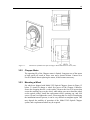
Rack Mount Option
The Model 3510 Rack Mount Kit is a Chopper accessory that allows one or two
Chopper Controllers to be mounted in a standard rack. The kit consists of two
short ears, one long ear, one rack plate, and six 6-32 flathead screws. The figure
below illustrates how to use the rack mount kit to mount a single Chopper
Controller or two Chopper Controllers side-by-side.
Figure 13:
3.4
Rack Mount Kit for Model 3502 Optical Chopper
Initial Setup
WARNING
The Model 3502 Optical Chopper Controller is intended for use ONLY
with New Focus Model 3502 Optical Chopper motor heads.
Connection of other devices to the unit’s motor connectors may cause
damage to the unit or the connected device, fire, and/or personal
injury.
WARNING
Before operating the Model 3502 Optical Chopper
thoroughly read and understand this User’s Manual!
Controller,
This section contains information on how to connect Model 3502 Optical
Chopper Controller to your local mains power and how to connect the Chopper
Head to the Chopper Controller.
23
3.4.1
Power
Make sure that that power switch is in the OFF position. Connect the male end
of the provided AC power cable to the mains supply. Connect the female end to
the three-pronged input receptacle on the back of the Chopper Controller.
WARNING
To avoid electric shock, connect the instrument to building earthground, 3-prong receptacles by using the supplied power cord only.
Failure to observe this precaution can result in damage to the product,
fire, severe injury, or death.
WARNING
Do not position this product in such a manner that would make it
difficult to disconnect the power cord.
WARNING
Position the equipment so that access to the mains ON/OFF switch is
readily available. In the event of a hazard, press the grey Power switch
on the lower right of the front panel to the OFF position to turn power
OFF to the internal electronics and fully disconnect the power cord of
the Controller from mains power.
3.4.2
Connecting the Chopper Head to the Chopper Controller
Make sure that the power switch is in the OFF position. Connect the Chopper
Head to the Controller with the provided standard shielded Ethernet cable by
plugging the smaller modular connector of the cable into the Chopper Head and
the larger connector into the MOTOR input on the rear panel of the Chopper
Controller.
3.4.3
Connecting the Chopper Controller to a Computer via USB
The Model 3502 Optical Chopper Controller can be connected to a computer
with a standard USB-A to USB-B cable for computer control and
communication.
3.5
Operation
When the unit is turned on the unit performs a series of internal verifications, the
word PASS is briefly displayed on the 5-digit LED numeric display, and it
shows its driving frequency setpoint. The unit is then ready to operate the
Chopper Head.
24
3.5.1
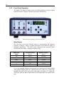
Front Panel Operation
The Model 3502 Optical Chopper can be operated manually by keying in control
functions from the Chopper Controller front panel shown below.
Figure 14:
Model 3502 Optical Chopper Controller front panel.
Wheel Button
The User may select from different wheels to accommodate the chopping
frequency of interest. Single- or double-slot wheels are provided for single- or
dual-path experiments. The table below summarizes the provided wheel
selection and each wheel’s chopping frequency range.
Wheel Type
Lowest Frequency
Highest Frequency
(slots)
(Fouter)
(Fouter)
100
200 Hz
10.65 kHz
60
120 Hz
6.40 kHz
42/30
84 Hz
4.48 kHz
7/5
14 Hz
746 Hz
2
4 Hz
213 Hz
60/2
See text
See text
Fouter is the chopping frequency as measured by an optical pick-up on the Model
3502 Optical Chopper Head. If a wheel has two sets of slots, Fouter refers to the
chopping frequency of the slots on the outer edge of the wheel. To change the
wheel type, push the Wheel button until the LED lights under the desired wheel
type.
25
For setups requiring very low chopping frequencies and high stability the 60/2slot wheel may be used. There is no wheel setting for this particular wheel on
the front panel—the 60-slot wheel setting must be selected. The actual chopping
frequency will differ from that displayed on the front panel by a factor of 2/60 =
1/30. For example, in NORMAL mode with the internal synthesizer set to 120 Hz
and with the 60-slot wheel setting selected, the actual chopping frequency
through the 2-slot segment of the wheel will be (1/30)·120 = 4 Hz.
Sync Button
The user may synchronize the chopping frequency to the Chopper's internal
synthesizer (INT), the rising edge (EXT+) or falling edge (EXT-) of an externallysupplied signal on Sync In. The motor’s rotational speed may be controlled
directly by applying a negative voltage to the Vext input.
When INT is selected, the signals available on the OUT 1 and OUT 2 outputs (see
the following section on the Mode button) on the back panel are phase-locked to
the internal synthesizer. When using the INT setting, a signal applied to Sync In
has no effect on the device’s operation.
When an external signal is used, either with EXT+ or EXT-, the signals available
on the OUT 1 and OUT 2 outputs are instead phase-locked to the external signal.
In EXT+ and EXT- modes the output from Synth Out (described below) is not
locked to, and does not have the same frequency as, the external signal and
remains at the frequency setpoint set on the front panel.
When Vext is selected, the user may drive the motor directly with an analog
voltage (-10 V to 0 V) applied at Vext on the back panel. When using Vext or INT, a
signal applied to the Sync In input has no effect on the Chopper. In this setting,
the signals available on OUT 1 and OUT 2 are frequency- and phase-locked to the
chopping frequency measured using the photo-interrupt on the Chopper Head,
Fouter. Note that these signals will therefore only be as stable as the externallycontrolled chopping frequency.
To change the Sync source, press the Sync button until the LED under the
desired Sync source lights.
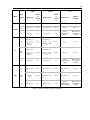
Mode Button
The Mode button allows the User to change the frequency that Fouter will lock to
in addition to the reference signals available at OUT 1 and OUT 2 (rear panel).
The table below gives the locking frequency of Fouter and the reference signals
available at OUT 1 and OUT 2, for each Mode setting.
In the table, the following definitions are used:
Fsync: frequency of the Sync source
Fouter: chopping frequency of outer slots as measured by IR sensor
Finner: chopping frequency of the inner slots; for single-slot wheels Fouter
is the chopping frequency, and Finner is undefined.
26
Mode Setting
Fouter locked to
OUT 1
OUT 2
H/S
(H/S)FSync
(H/S)Fsync
[H/(7S)]Fsync
+/-
Fsync
Fouter – Finner
Fouter + Finner
Normal
Fsync
5Fsync
Finner
Table 1: Chopping frequency and outputs vs. mode setting.
For all wheels with a dual slot pattern (except for the 60/2-slot wheel), Fouter =
7/5·Finner. Therefore, Fouter – Finner = 2/7·Fsync and Fouter + Finner = 12/7·Fsync.
When the Sync setting is Vext, the reference signals available at OUT 1 and OUT 2
are generated with respect to the measured chopping signal Fouter.
Please see Table 2 on page 29 for a complete reference of output signals
according to Mode selection.
To change the Mode, push the Mode key until the LED under the desired
selection lights up.
Sync In
A TTL signal applied to the Sync In input will be used as a frequency and phase
reference in EXT+ and EXT- modes. TTL pulses can be used to trigger the
Chopper Controller as long as they are longer than 1 s.
Synth Out
The signal provided by the internal synthesizer is available on this output.
F Outer
The signal from the optical pick-up on the Chopper Head is available on this
output as a TTL signal.
Set Button
The Set button selects which instrument parameter you can modify using the
cursor keys. Press Set until the LED lights under the desired parameter: FREQ,
PHASE, H, S, RECALL, or STORE. Each of these parameters is described below.
The up arrow and down arrow keys will then change the parameter value. In
some cases, the left arrow and right arrow keys select the significant digit to be
modified.
Set: FREQ
The user may set the internal synthesizer frequency depending on the Sync
source selected. When EXT-, EXT+ or Vext sync has been selected, the frequency
may range from 4.00 Hz to 99.9 kHz.
27
When the INT setting is selected for the Sync source, the synthesizer frequency
will be restricted to the working range of the particular chopping wheel. In H/S
mode this range will be modified by the user-specified values of H and S
according to:
Fmax = (S/H)·Fouter, highest,
and
Fmin = (S/H)·Fouter, lowest.
The internal synthesizer frequency may be set to three significant digits. The
significant digit to be modified may be selected by the left and right arrow keys.
The magnitude of the digit may be changed with the up and down arrow keys. If
the display overflows or underflows, the display will change between the Hz/kHz
LEDs and move the decimal point to maintain three significant digits of
resolution.
Set: PHASE
The phase delay may be set from -180.0° to +179.0°. The phase shift is always
with respect to Fouter. In NORMAL and +/- modes, Fouter = Fsync. In H/S mode Fouter
= (H/S)·Fsync.
When the phase adjustment is active, the DEG LED will be lit. The left and right
arrow keys can be used to select the significant digit to modify, and this digit
will blink. The up and down arrow keys can be used to change the magnitude of
the digit.
Set: H and S
In H/S mode the user may lock the Chopper to a harmonic of the sync frequency.
H is set to the harmonic of interest. Use the up arrow and down arrow keys to set
H to an integer value from 1 to 15.
The user may lock the Chopper to a subharmonic of the sync frequency. S is set
to the subharmonic of interest. Use the up arrow and down arrow keys to set S to
an integer value from 1 to 15.
S and H may be set in any combination.
Set: STORE
The user may store an instrument setup in one of two ways. First, the control
unit will retain the control settings when the power is removed. When power is
restored, the instrument will recall the last control settings used.
Second, the user may utilize one of nine programmable instrument set-ups. To
store an instrument setup press the Set button until STORE is lit. Then, use the
up and down arrow keys to assign the instrument setup number, 1-9. Press the
left or right arrow key to store the instrument’s settings. Location 0 is reserved
for the factory default settings (see the Default Settings section below).
28
Set: RECALL
The user may recall an instrument setup in one of two ways. Firstly, on power
up, the instrument will recall the last control settings used.
Secondly, a previously stored setup can be recalled by pressing the Set button
until the RECALL LED is lit. The up and down arrow keys are used to select the
instrument setup number, again, ranging from 0 to 9. Press the left or right
arrow key to recall the displayed instrument setup. The display will blink when
the recall process is complete. Location 0 is reserved for the factory default
settings.
Set: Default Settings
Location 0 is reserved for the factory default settings: Wheel is set to 42/30, Sync
is set to INT, Mode is set to NORMAL, and the internal synthesizer frequency is set
to 84 Hz.
Measure Button
The Measure button is used to select which frequency measurement (Fsync, Fouter,
OUT 1 or OUT 2) is displayed on the front panel. The instrument will continue to
measure and update the display until another function key is pressed. To change
the parameter to be measured, press the Measure button until the LED lights
under the desired parameter.
UNLCK LED
The red UNLCK LED indicates when the Chopper is not synchronized to an
internal or external sync frequency. In addition, the UNLCK LED will blink
when an external sync frequency exceeds the limits for a particular wheel.
USB LED
The USB LED lights when the Chopper Controller is connected to a computer.
29
OUT 1
Mode
Phase
Sync
Source
OUT 2
Output Freq.
is
locked
Fouter
Phase
Output Freq.
to
is
locked
Output Freq.
Phase is
locked to
to
Int
5·(Int. Fsync)
Int. Fsync
(5/7)·(Int. Fsync)
Int. Fsync
Int. Fsync
Int. Fsync
Ext+,
Ext-
5·(Ext. Fsync)
Ext. Fsync
(5/7)·(Ext. Fsync)
Ext. Fsync
Ext. Fsync
Ext. Fsync
Vext
5·(Fouter)
Fouter
(5/7)·( Fouter)
Fouter
Freq. is
controlled by ext.
voltage.
Motor phase is
not controlled
internally.
Int. Fsync
Int. Fsync
Int. Fsync
1
Normal
(2/7)·(Int. Fsync)
Int
i.e. Fouter - Finner
with Fouter =
(7/5)·Finner
(12/7)·(Int. Fsync)
Int. Fsync
(2/7)·(Ext. Fsync)
+/-
(12/7)·(Ext. Fsync)
1
Ext+,
Ext-
i.e. Fouter - Finner
with Fouter =
(7/5)·Finner
Ext. Fsync
i.e. Fouter + Finner
with Fouter = (7/5)·
Finner
Ext. Fsync
Ext. Fsync
Ext. Fsync
Vext
(2/7)·(Fouter)
Fouter
(12/7)·( Fouter)
Fouter
Freq. is
controlled by ext.
voltage.
Motor phase is
not controlled
internally.
Int
(H/S)·(Int. Fsync)
Int. Fsync
(H/7S)·(Int. Fsync)
Int. Fsync
(H/S)·(Int. Fsync)
Int. Fsync
Ext+,
Ext-
(H/S)·(Ext.
Fsync)
Ext. Fsync
(H/7S)·(Ext. Fsync)
Ext. Fsync
(H/S)·(Ext. Fsync)
Ext. Fsync
Vext
(H/S)·(Fouter)
Fouter
(H/7S)·( Fouter)
Fouter
Freq. is
controlled by
external voltage.
Motor phase is
not controlled
internally.
1
H/S
i.e. Fouter + Finner
with Fouter = (7/5)·
Finner
Table 2: Summary of Modes, Settings and Outputs.
30
3.6
Back Panel Operation
The back panel of 3502 Optical Chopper Controller provides the functions
operation described below.
Figure 15:
Model 3502 Optical Chopper Controller back panel.
CAUTION
Do not block the rear panel of the Controller. Ensure a minimum
clearance of 30” for adequate ventilation of the device. Blocking the
normal convective airflow around the unit, or thermally insulating the
unit, can result in severe injury, damage to the product, and/or fire.
OUT 1
The function of the OUT 1 output depends on the instrument’s operating mode.
In H/S mode, the instrument provides a TTL-level signal at frequency
(H/S)·Fsync. In +/- mode the frequency at OUT 1 is Fouter - Finner, and in NORMAL
mode the frequency is 5·Fouter. This information is also summarized in Table 2
on page 29.
OUT 2
The function of the OUT 2 output depends on the instrument’s operating mode.
In H/S mode, the instrument provides the user with a TTL-level signal at
frequency [H/(7·S)] ·Fsync. In +/- mode the frequency at OUT 2 is Fouter+Finner.
In NORMAL mode the frequency is Finner. This information is also summarized in
Table 2 on page 29.
Vext
The Vext BNC input connector can be used to supply an external 0 to -10 V DC
voltage. When the Sync setting is Vext, the user may drive the Chopper motor
directly with this input DC voltage. In this case, 0 to -10 V DC corresponds to 0
to 100% of the highest motor speed, respectively.
31
MOTOR socket
The input marked MOTOR on the rear panel is used to connect the 3502 Optical
Chopper Head to the Chopper Controller with the shielded Ethernet cable
provided.
USB 2.0
The USB-B input port is used in connecting the Chopper Controller to a host
computer system. This allows the instrument to be controlled remotely via USB
interface.
Power Entry Module
The AC power is connected at the power entry module on the rear panel. The
power module has been chosen for global operation, and North American and
European power cords are supplied.
Motor Cable
The cable that connects the Chopper Controller to the Chopper Head is a sixconductor shielded Ethernet cable. Connect the cable from the connector on the
side of the Chopper Head to the MOTOR connector on the back panel of the
Chopper Controller. The instrument has been tested with cable lengths up to 25
feet, but the Chopper is supplied with a shorter cable.
32
Computer Interfacing
4
4.1
Introduction
The Model 3502 Optical Chopper can be controlled remotely over the USB 2.0
interface either via an intuitive, Windows-based Graphical User Interface (GUI)
application or via commands sent from a host PC.
Before connecting the instrument to the USB interface the user should install the
application included on the flash drive that accompanies the Model 3502 Optical
Chopper. The installer will install not only the GUI application, but also the
appropriate USB drivers and programming examples (LabVIEW and C#), and
supporting documentation. Please consult the ‘Readme Chopper Application.pdf’
document on the flash drive for installation instructions and a list of the files that
are installed. This document also addresses important considerations when
installing the software on 32-bit or 64-bit operating systems.
Although the user can choose a custom installation directory, the default
location is under ‘Program Files\New Focus\New Focus Chopper Application\’. Three
sub-directories are installed here: ‘Bin’, containing the New Focus Chopper
Application and supporting files; ‘Docs’, containing documentation of the GUI
Application, the programming examples and the Newport USB library API
documentation; and ‘Samples’, containing C# and LabVIEW examples to get
you started with remote operation of the Model 3502 Optical Chopper. Please
note that these examples are provided for reference only.
The latest GUI application version and supporting files can always be found on
the Model 3502 Optical Chopper’s product page at newport.com.
4.2
Using the Graphical User Interface (GUI)
The GUI allows full control of the Model 3502 Optical Chopper’s front panel
functions (save for turning the Controller On/Off). Below is a screenshot of the
‘3502 Optical Chopper Application’ GUI window.
33
Figure 16:
4.2.1
Model 3502 Optical Chopper Application window.
A Quick Start: How to Use the ‘New Focus Chopper
Application’
1. Turn the Model 3502 Optical Chopper Controller on using the power
button on the front panel of the Controller.
2. Open the New Focus Chopper Application. If you turn on the Chopper
after opening the application you may need to select the Connect menu
item from the File menu.
3. The
icon at the lower left corner of the window indicates
that the GUI has successfully established a connection to the Chopper
Controller.
4. Operating parameters can now be set from the application window: radio
buttons are used to select the Wheel, Sync mode, and Mode of operation.
5. The desired chopping frequency is set by entering the value in Hz in the
topmost text entry field and pressing the Set Freq button. Similarly, the
chopping phase, H, and S can all be changed. Note that although you can
set values for the chopping frequency, phase, H, and S via the GUI, the
present values of these setpoints can only be read through the front panel
of the Chopper Controller.
6. Up to nine setup states can be stored using the Store button on the left.
This is done by first assigning the setup state a number (1-9) from the
dropdown menu next to the Store button, then clicking the button.
Similarly, a setup state can be recalled using the Recall button.
7. The frequency of Sync In, Fouter, OUT 1, and OUT 2 can be measured by
clicking their respective button in the Measure field. The magnitude of the
frequency measured (in Hz) will be shown in the numeric display field.
8. To exit the application, either close the window or select ‘Exit’ from the
‘File’ menu.
34
4.3
USB Communication
To control the Model 3502 Optical Chopper remotely without using the GUI
application, commands can be issued directly over USB using the Newport USB
library. The API is described in detail in the document ‘Chopper USB Libraries
API User’s Manual.pdf’. This file is installed in the ‘Docs’ folder. After consulting
this document, the best way to become acquainted with the procedure for
controlling the Model 3502 Optical Chopper programmatically is to review the
provided C# and LabVIEW examples.
4.4
Command Index and Conventions
In the brief command index below and detailed command descriptions that
follow in the next subsection several conventions are used.
Some commands may be used to set and query an operating parameter. For
example, the PHS command can be used to set the chopping phase (PHS900) or
to read the value of the phase (PHS?). If a command allows querying, it will be
followed by a ‘?’. If a command is not a query, there will be no response from
the Chopper Controller.
A bracket pair ‘[ ]’ indicates that the command accepts a data value. Data ranges
are given in parentheses ‘( )’. Do not use a decimal point or comma in data
passed to the Chopper Controller this way. For example, to set the chopping
frequency to 1.23 kHz, send the command OSC123000. To set the phase to -90
degrees, send the command PHS-90. Note that data returned from the Controller
will have decimal points included.
Multiple commands on a single line must be separated by a semicolon ‘;’.
Table 3 below summarizes all commands.
35
Measures a given frequency.
FR*?
HAR[ ]?
IDN?
1 = Fsync, 2 = Fouter, 3 = OUT 1, 4 = OUT 2.
Sets the harmonic multiplier H (1 - 15).
Identification query. Returns “NEW FOCUS 3502 CHOPPER
<Firmware version> <Firmware date>, SN<Serial Number>”.
Duplicates the action of pressing a front panel key:
KEY*
MEM*
0 = Right arrow, 1 = Down arrow, 2 = Up arrow, 3 = Left arrow,
4 = Set, 5 = Measure, 6 = Mode, 7 = Sync, 8 = Wheel.
Accesses instrument set-up memory. 0 = Store, 1 = Recall. Use with
STO and RCL commands.
MOD*?
Selects the instrument mode. 0 = H/S, 1 = +/-, 2 = NORMAL.
OSC[ ]?
Sets the internal synthesizer frequency to three significant digits. (4.00
Hz to 99.9 kHz in EXT+/EXT- mode; range automatically limited in INT
mode).
PHS[ ]?
Sets the phase delay (-180.0 to +179.0).
RCL[ ]?
Selects instrument set-up for recall (0 - 9). 0 - factory default set-up.
Use with MEM1 command.
SET*
Selects the parameter modified by the arrow keys: 0 - Synth frequency,
1 - Phase, 2 - Harmonic multiplier, 3 - Subharmonic divisor, 4 - Recall
set-up, 5 - Store set-up
STO[ ]?
Selects instrument set-up for storage (1-9). Use with MEM command.
SUB[ ]?
Sets subharmonic divide ratio S (= 1 - 15).
SYN[ ]?
Selects the source of the sync frequency. 0 = Vext, 1 = EXT+, 2 = EXT-, 3
= INT.
WHL*?
Selects the wheel. 0 = 60 slot wheel, 1 = 42/30 slot wheel, 2 = 7/5 slot
wheel, 3 = 2 slot wheel, 4 = 100 slot wheel.
Table 3: Summary of computer control commands.
36
4.5
Command Description
FR*?
Description
Frequency query.
Syntax
FR*?
Remarks
The FR* command is used to query the following frequencies
associated with the Measure key on the Chopper front panel: Fsync,
Fouter, OUT 1, and OUT 2. Data is returned in Hz.
FR1?
FR2?
FR3?
FR4?
Example
Query Fsync
Query Fouter
Query frequency of OUT 1
Query frequency of OUT 2
The chopping frequency is 1.23 kHz, and the Chopper is in
NORMAL mode.
FR3?
FR36150.0
Query.
Response. The frequency at OUT 1 is
6.15 kHz.
HAR[ ]?
Description
Set and query H.
Syntax
HAR[ ]?
Remarks
The HAR command sets and queries the harmonic multiplier H,
which is used in H/S mode. The data may range from 1 to 15.
Example
HAR2
HAR?
HAR2
Command. Sets H to 2.
Query.
Response. H is currently set to 2.
37
IDN?
Description
Identification query.
Syntax
IDN?
Remarks
Returns the following string identifying the Chopper: "NEW
FOCUS 3502 CHOPPER <Firmware version> <Firmware date>,
SN<Serial Number>".
Example
IDN?
NEW FOCUS
3502
CHOPPER
1.16
5/05/14,
SNP0004
Query.
Response. The firmware version is 1.16,
the firmware date is 5/05/14, and the
serial number of the unit is P0004.
KEY?
Description
Duplicates the action of pushing a front panel button.
Syntax
KEY?
Remarks
The KEY command duplicates the action of pushing one of the 9
black front panel buttons. The nine options are as follows:
KEY0
KEY1
KEY2
KEY3
KEY4
KEY5
KEY6
KEY7
KEY8
Right arrow
Down arrow
Up arrow
Left arrow
Set
Measure
Mode
Sync
Wheel
38
MEM?
Description
Store and recall instrumental set-ups.
Syntax
MEM?
Remarks
The MEM command, along with the STO and RCL commands, is
used to store and recall one of the 9 instrumental set-ups. After
selecting which instrument set-up number to use (1 through 9)
using the STO command, MEM0 will store the current instrument
set-up. After selecting which instrument set-up to recall using the
RCL command, MEM1 recalls the selected set-up.
Example
STO5
MEM0
RCL1
MEM1
Selects location #5 for setup storage
Saves setup in location #5
Selects location #1 setup recall
Recalls setup in location #1
MOD*?
Description
Select and query the mode of operation.
Syntax
MOD*?
Remarks
The MOD command allows the user to query the Chopper’s
operating mode and to set the Chopper operating mode as follows:
MOD0
MOD1
MOD2
H/S
+/NORMAL
MOD2
Command. Operating mode set to
NORMAL.
Query.
Response. Operating mode is NORMAL.
Example
MOD?
MOD2
39
OSC[ ]?
Description
Set and query the synthesizer frequency.
Syntax
OSC[ ]?
Remarks
The OSC command sets and queries the internal synthesizer. In INT
Sync mode setting the synthesizer frequency will set the chopping
frequency. In INT Sync mode the data supplied by the OSC
command is limited by the Chopper wheel minimum and
maximum chopping frequencies. In the other modes of operation,
the data may range from 4.00 to 99.9 kHz. Only three digits of
resolution are available. The data is entered in Hz, and no decimal
point should be included.
Example
OSC54300
OSC?
OSC543.00
Command. Sets the internal synthesizer to
543 Hz.
Query.
Response. The internal synthesizer’s
frequency is set to 543 Hz.
PHS[ ]?
Description
Set and query the phase delay.
Syntax
PHS[ ]?
Remarks
The PHS command sets and queries the phase shifter. The data
may range from -180.0 to +179.0 degrees. Do not use a decimal
point in the data.
Example
PHS-1234
PHS?
PHS-123.4
PHS222
Command. Set the phase shift to -123.4
degrees.
Query.
Response. The phase shift is set to -123.4
degrees.
Command. Set the phase shift to 22.2
degrees.
40
RCL[ ]?
Description
Selects instrument set-up for recall.
Syntax
RCL[ ]?
Remarks
The RCL command will select a formerly stored instrument set-up.
The RCL? query will return the recall set-up number. The data
may range between 0 and 9. Recall of set-up “0” will restore the
Model 3502 Optical Chopper to factory default settings. RCL is
used with MEM1 to recall the instrument set-up.
Example
RCL0
MEM1
RCL4
RCL?
RCL4
MEM1
Command. Select factory default setup for
recall.
Command. Recalls factory default setup.
Command. Select location #4 for setup
recall.
Query.
Response. The active location for recall is
location #4.
Command. Recalls setup in location #4.
SET*
Description
Selects the parameters to be modified by the arrow keys.
Syntax
SET*
Remarks
The SET command selects which parameter is activated so that it
can be changed by the arrow keys.
SET0
SET1
SET2
SET3
SET4
SET5
Synthesizer frequency
Phase
H
S
Recall
Store
41
STO[ ]?
Description
Selects instrument set-up for storage.
Syntax
STO[ ]?
Remarks
The STO command selects the instrument set-up number in which
to store the current Chopper set-up. The STO? query will return
the selected instrument set up number. The data may range from 1
to 9. STO is used with MEMO to store the instrument set-up.
Example
STO9
STO?
STO9
MEM0
Command. Select location #9 for setup
storage.
Query.
Response. Location #9 is selected for
setup recall.
Command. Recalls setup #9.
SUB[ ]?
Description
Set and query S.
Syntax
SUB[ ]?
Remarks
The SUB command sets and queries S, the subharmonic divide
ratio which is used in H/S mode. The data may range from 1 to 15.
Example
SUB7
SUB?
SUB7
Command. Set subharmonic divide ratio
to 7.
Query.
Response. Subharmonic divide ratio is 7.
42
SYN[ ]?
Description
Set and query the source used for synchronization.
Syntax
SYN[ ]?
Remarks
The SYN command sets and queries the frequency source used for
synchronization.
SYN0
SYN1
SYN2
SYN3
SYN?
Vext
Ext+
ExtINT
Query
SYN3
SYN?
SYN3
Command. Set sync source to INT.
Query.
Response. Sync source is set to INT.
Example
WHL[ ]?
Description
Set and query the type of chopping wheel being used.
Syntax
WHL[ ]?
Remarks
The WHL command sets and queries the type of chopping wheel
that is being used:
WHL0
WHL1
WHL2
WHL3
WHL4
WHL?
60-slot wheel
42/30-slot wheel
7/5-slot wheel
2-slot wheel
100-slot wheel
Query wheel type
WHL1
WHL?
WHL1
Command. Select the 42/30-slot wheel.
Query.
Response. Selected wheel is the 42/30slot wheel.
Example
43
Troubleshooting
5
CAUTION
There are no user serviceable parts inside the Model 3502 Optical
Chopper Controller or Motor Head. Work performed by persons not
authorized by New Focus will void the warranty.
5.1
Normal Startup Operation
When the Chopper Controller is properly connected to the power mains and a
Chopper Head, and is turned on, the front panel LEDs will blink and the display
will show PASS before recalling the last Chopper Controller set up. The motor
should begin turning and come to speed within about one minute.
5.2
Symptoms and Steps to Follow
If nothing happens:
Check that the power cord is connected to the Chopper Controller.
Check that the Chopper Head is connected to the Chopper Controller. Do not
connect the Chopper Head when the Chopper Control unit is powered on.
Fails test at start up:
Please contact New Focus for service.
Motor fails to turn:
With power removed from the control unit, check that the wheel is free to turn
without obstructions. Also, this condition may be caused by a broken shielded
Ethernet cable between the Chopper Controller and the Chopper Head.
Substitution of a known functional shielded Ethernet cable is the best solution.
Motor spins down and stops when sync frequency is changed:
The Chopper Controller will stop driving the motor in the Chopper Head if an
externally-supplied sync frequency is outside the range of the chopping
frequencies allowed for a given wheel setting. Verify that this external signal is
of the correct frequency.
44
Synchronization to an external signal is unreliable:
Verify that the pulse width of the external trigger pulse is at least 1 μs long. Use
an oscilloscope with a high impedance input to monitor the external signal while
it is connected to the Chopper Controller. The input signal should have valid
TTL voltage levels.
Motor oscillates wildly:
Recall the factory default settings. This will place the instrument into known
conditions. If the oscillation stops, then the signal supplied via Sync In may have
been unstable. Verify the stability of the input signal with an oscilloscope or
frequency counter. The frequency of the signal on Sync In may have been
outside of operating limits which are determined by the operating Mode, H, S,
and the Wheel setting. Refer to the entry on the FREQ setting in Section 3.5.1 on
page 24 for more details.
Observe the signal at Fouter on an oscilloscope. If the cable or optical sensor is
damaged, the signal will remain high or low. If this is the case, replace the cable
between the Chopper Controller and the Chopper Head.
Check for the correct wheel setting on the front panel.
45
Specifications
6
Chopping Frequency
6.1
Please note that specifications are subject to change without notice.
6.2
Jitter (s p-p, typical)
Min. Freq.
Max. Freq.
Wheel
(Fouter)
(Fouter)
@ Min.
Freq.
@ Max.
Freq.
100
60
42/30
7/5
2
200 Hz
120 Hz
84 Hz
14 Hz
4 Hz
10.65 KHz
6.40 KHz
4.48 KHz
746 Hz
213 Hz
200
150
150
1000
2000
5
3
5
15
50
Internal Synthesizer
Stability
100 ppm after one hour warm-up.
Drift
Less than 10 ppm/°C.
Accuracy
< 1/5 of least significant digit.
Resolution
4.00 Hz - 99.9 kHz, 3 significant digits.
Range limits (INT)
Upper: [Highest wheel frequency]·S/H.
Lower: [Lowest wheel frequency]·S/H.
Range limits (EXT)
6.3
4.00 Hz – 99.9 kHz
Reference Input
Sync In
TTL-level pulse, with same frequency limits as internal
oscillator.
Pulse width ≥ 1 μs.
46
6.4
Reference Output
Sync Out
TTL level square wave, may be used as free-running
oscillator when using EXT+, EXT- or Vext Sync setting.
Fouter
TTL-level square wave at the chopping frequency.
OUT 1
TTL level pulse:
5·Fouter in NORMAL mode
Fouter - Finner in +/- mode
(H/S)·Fouter in H/S mode.
OUT 2
TTL level pulse:
Finner in NORMAL mode
Fouter + Finner in +/- mode
[H/(7·S)]·Fsync in H/S mode.
6.5
6.6
Phase Shifter
Range:
-180.0° to +179.0°
Resolution:
0.1°, increasing to 0.25° at 6.4 kHz.
Harmonic Locking
Subharmonic (S):
1 – 15
Harmonic (H):
1 – 15
Note: S and H may be set in any combination.
6.7
External Voltage Control
0 to -10.0 V DC for 0 to 100% of maximum chopping frequency.
6.8
General
Net Weight:
5.7 pounds (Chopper Head assembly included)
Power Input:
100-240 VAC, 50-60 Hz.
47
Maintenance and Service
7
7.1
Enclosure Cleaning
Before cleaning the enclosure of the Model 3502 Optical Chopper Controller,
the power cord must be disconnected from the wall socket and from the unit.
The source enclosure should only be cleaned with a mild soapy water solution
applied to a damp lint-free cloth. Do not use an acetone or alcohol solution; this
will damage the finish of the enclosure.
7.2
Technical Support
Information and advice about the operation of any New Focus product is
available from our technical support engineers.
Hours:
8:00–5:00 PST, M-F (excluding holidays)
Toll Free:
1-866-NUFOCUS (1-866-683-6287)
(from the USA & Canada only)
Phone:
(408) 284-6808
Support is also available via email:
Email:
[email protected]
We typically respond within one business day.
7.3
Technical Support Contacts
North America
New Focus
3635 Peterson Way
Santa Clara, CA 95054
Telephone: (866) 683-6287
Telephone: (408) 919-1500
48
Europe
Newport/MICRO-CONTROLE S.A.
Zone Industrielle
45340 Beaune la Rolande, FRANCE
Telephone: (33) 02 38 40 51 56
Asia
Newport Opto-Electronics Technologies
中国 上海市 爱都路 253号 第3号楼 3层 C部位, 邮编 200131
253 Aidu Road, Bld #3, Flr 3, Sec C, Shanghai 200131, China
Telephone: +86-21-5046 2300
Fax: +86-21-5046 2323
7.4
Service
Your Model 3502 Optical Chopper Controller and Chopper Head have been
designed to provide years of trouble-free operation. Virtually no maintenance is
required except for ensuring that the unit is not damaged, contaminated, or used
in an unsafe manner.
Obtaining Service
The Model 3502 Optical Chopper Controller and Chopper Head contain no user
serviceable parts. To obtain information regarding factory service, contact New
Focus. Please have the following information available:
Instrument model number (on the rear panel).
Instrument serial number (on the rear panel).
Description of the problem.
If the instrument is to be returned to New Focus, you will be given a Return
Material Authorization (RMA) number, which you should reference in your
shipping documents.
7.5
Warranty
New Focus, a Newport Corporation company, guarantees its products to be free
of defects for one year from the date of shipment. This is in lieu of all other
guarantees, expressed or implied, and does not cover incidental or consequential
loss.
49
Note that the life of the motor is limited. Long-term high-speed use of the motor
will result in faster wear and a shorter lifetime. Because of this limited lifetime,
the Chopper Head has a 90 day warranty, while all other parts have a one year
warranty.