1
F-RCL Series
Manual Angled Ribbon Fiber Cleaver
User’s Manual
2
Warranty
Newport Corporation warrants that this product will be free from defects in
material and workmanship and will comply with Newport’s published
specifications at the time of sale for a period of one year from date of
shipment. If found to be defective during the warranty period, the product
will either be repaired or replaced at Newport's option.
To exercise this warranty, write or call your local Newport office or
representative, or contact Newport headquarters in Irvine, California. You
will be given prompt assistance and return instructions. Send the product,
freight prepaid, to the indicated service facility. Repairs will be made and the
instrument returned freight prepaid. Repaired products are warranted for the
remainder of the original warranty period or 90 days, whichever first occurs.
Limitation of Warranty
The above warranties do not apply to products which have been repaired or
modified without Newport’s written approval, or products subjected to
unusual physical, thermal or electrical stress, improper installation, misuse,
abuse, accident or negligence in use, storage, transportation or handling. This
warranty also does not apply to Diamond blades, fuses, batteries, or damage
from battery leakage.
THIS WARRANTY IS IN LIEU OF ALL OTHER WARRANTIES,
EXPRESSED OR IMPLIED, INCLUDING ANY IMPLIED WARRANTY
OF MERCHANTABILITY OR FITNESS FOR A PARTICULAR USE.
NEWPORT CORPORATION SHALL NOT BE LIABLE FOR ANY
INDIRECT, SPECIAL, OR CONSEQUENTIAL DAMAGES RESULTING
FROM THE PURCHASE OR USE OF ITS PRODUCTS.
First printing 2007
© 2007 by Newport Corporation, Irvine, CA. All rights reserved. No part of
this manual may be reproduced or copied without the prior written approval
of Newport Corporation.
This manual has been provided for information only and product
specifications are subject to change without notice. Any change will be
reflected in future printings.
Newport Corporation
1791 Deere Avenue
Irvine, CA, 92606
USA
Part No. 45455-01, Rev. A
3
Confidentiality & Proprietary Rights
Reservation of Title:
The Newport programs and all materials furnished or produced in connection
with them ("Related Materials") contain trade secrets of Newport and are for
use only in the manner expressly permitted. Newport claims and reserves all
rights and benefits afforded under law in the Programs provided by Newport
Corporation.
Newport shall retain full ownership of Intellectual Property Rights in and to
all development, process, align or assembly technologies developed and other
derivative work that may be developed by Newport. Customer shall not
challenge, or cause any third party to challenge the rights of Newport.
Preservation of Secrecy and Confidentiality and Restrictions to Access:
Customer shall protect the Newport Programs and Related Materials as trade
secrets of Newport, and shall devote its best efforts to ensure that all its
personnel protect the Newport Programs as trade secrets of Newport
Corporation. Customer shall not at any time disclose Newport's trade secrets
to any other person, firm, organization, or employee that does not need
(consistent with Customer's right of use hereunder) to obtain access to the
Newport Programs and Related Materials. These restrictions shall not apply
to information (1) generally known to the public or obtainable from public
sources; (2) readily apparent from the keyboard operations, visual display, or
output reports of the Programs; 3) previously in the possession of Customer
or subsequently developed or acquired without reliance on the Newport
Programs; or (4) approved by Newport for release without restriction.
Service Information
This section contains information regarding factory service for the source.
The user should not attempt any maintenance or service of the system or
optional equipment beyond the procedures outlined in this manual. Any
problem that cannot be resolved should be referred to Newport Corporation.
4
Technical Support Contacts
North America & Asia
Europe
Newport Corporation Service Dept.
Newport/Micro-Controle S.A.
1791 Deere Ave.
Zone Industrielle
Irvine, CA 92606
45340 Beaune la Rolande, FRANCE
Telephone: (949) 253-1694
Telephone: (33) 02 38 40 51 49
Telephone: (800) 222-6440 x31694
Asia
Newport Opto-Electronics
Technologies
中国 上海市 爱都路 253号 第3号楼 3层
C部位, 邮编 200131
253 Aidu Road, Bld #3, Flr 3, Sec C,
Shanghai 200131, China
Telephone: +86-21-5046 2300
Fax: +86-21-5046 2323
Newport Corporation Calling Procedure
If there are any defects in material or workmanship or a failure to meet
specifications, promptly notify Newport's Returns Department by calling 1-800-2226440 or by visiting our website at www.newport.com/returns within the warranty
period to obtain a Return Material Authorization Number (RMA#). Return the
product to Newport Corporation, freight prepaid, clearly marked with the RMA# and
we will either repair or replace it at our discretion. Newport is not responsible for
damage occurring in transit and is not obligated to accept products returned without
an RMA#. E-mail: [email protected]
When calling Newport Corporation, please provide the customer care representative
with the following information:
•
•
•
Your Contact Information
Serial number or original order number
Description of problem (i.e., hardware or software)
To help our Technical Support Representatives diagnose your problem, please note the
following conditions:
•
•
•
•
•
Is the system used for manufacturing or research and development?
What was the state of the system right before the problem?
Have you seen this problem before? If so, how often?
Can the system continue to operate with this problem? Or is the system nonoperational?
Can you identify anything that was different before this problem occurred?
5
1.1
Contents
Warranty
2
Technical Support Contacts
4
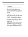
1.1
1.2
1.3
1.4
1.5
1.6
2
Contents........................................................................................ 5
Introduction .................................................................................. 6
1.2.1 Angled Cleaving................................................................6
1.2.2 Angled Cleaving of Fiber Ribbons....................................6
Unpacking..................................................................................... 7
Installation .................................................................................... 7
Operating Principles ..................................................................... 8
1.5.1 Window Stripping .............................................................9
1.5.2 Clamping .........................................................................12
1.5.3 Cleaving...........................................................................13
1.5.4 Cleave Angle ...................................................................13
1.5.5 Adjustments.....................................................................14
1.5.6 Cleave Variability............................................................14
Maintenance ............................................................................... 15
1.6.1 Diamond Blade................................................................15
1.6.2 Shape of Cleaved Ends....................................................16
Factory Service Information
2.1
17
Service Form .............................................................................. 17
6
1.2
1.2.1
Introduction
Angled Cleaving
o Many applications in optical telecommunications, such as
pigtailing optical fiber to lasers, detectors or other optical
components require minimal optical noise.
o When the cleaved end face is angled away from the
perpendicular in the region of the fiber's core, any backreflected light is not transmitted down the optical fiber and so
does not contribute to optical noise. An 8° angle is sufficient
to reduce the collected light to around -60dB for a single
mode fiber.
1.2.2
Angled Cleaving of Fiber Ribbons
o The F-RCL Series Angled Ribbon Cleaving System is
designed to angle cleave multiple fibers in a ribbon. Angled
cleaved ribbon fibers are required to reduce back-reflections
in ribbon fibers which interface with arrays of photonic
components. It uses a patented technique of shearing the
optical fiber prior to cleaving giving a smooth angle cleaved
end.
o The F-RCL-8-4F cleaves fiber ribbons of up to 4 fibers with 8°
angles across the cores of 125µm single mode fibers coated
with encapsulation up to 1200µm wide with preset cleave
lengths of 5-15mm.
o The F-RCL-8-8F cleaves fiber ribbons of up to 8 fibers with 8°
angles across the cores of 125µm single mode fibers coated
with encapsulation up to 2200µm wide with preset cleave
lengths of 5-15mm.
o Newport also carries the F-CLX-8-3 and the F-CLX-0-3 which
produce, respectively, 8° angled and perpendicular cleaves
on the end of single fibers.
7
1.3
Unpacking
The F-RCL Series Angled Ribbon Cleaving System includes the following
components:
•
F-RCL Cleaving Tool, including two fiber clips (one attached to tool and one
removable).
•
The cleaving tool is held in a carry case.
•
The ribbon fiber must be window stripped prior to cleaving using a thermal
stripping tool. The following tool is recommended: JR-5 Thermal Stripping
Tool (manufactured by Sumitomo Electric) plus power supply
o Optionally, a stripping rig is available which can be used with
the JR-5 to obtain superior quality window-stripped ribbon
fiber
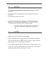
1.4
Installation
•
Unpack the various components from their packaging.
•
Remove small rubber sleeve which protects the diamond blade during shipping.
Check diamond blade is clean. NOTE: Use lint-free paper or rubber to clean the
diamond blade but never touch the diamond with metal
•
Turn on thermal stripper and allow it to warm up for 15 minutes, ensuring that unit
does not turn off by raising and lowering the lid every 5 minutes. Use the highest
temperature setting so that the stripper is warm to touch.
8
1.5
Operating Principles
Angled cleaving uses the following steps:
1. Window-strip fiber ribbon
2. Clamp stripped fibers at two positions
3. Deflect the clamped fibers laterally using an anvil to give:
•
Tension, because the fiber is stretched by the anvil
•
Shear, because the fibers are bent between the edge of the anvil and the
edge of the clamp
4. Scratch the tensioned and sheared fiber(s) using a diamond blade. The blade
moves at a tangential angle to reduce cutting stresses.
o All of the fibers in the ribbon must be clamped independent of each
other so that they can be tensioned and sheared independently.
The cleaving system achieves this by window-stripping the ribbon
using a thermal stripper. The coating is removed in the cleave area,
leaving coated ribbon on both sides of the stripped area of the
fibers.
o The fibers are then deflected by an anvil, giving both tension and
shear. Cleaving occurs when initiation scratches are introduced in
the tensioned and sheared fiber(s) using a diamond blade.
9
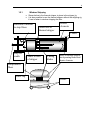
1.5.1
Window Stripping
o Shown below is the thermal stripper in place in the stripper jig.
o It is also possible to use the thermal stripper without the stripping rig
if care is taken in window stripping the fiber.
Direction of motion
to strip fibers
Slider bars of
thermal stripper
Heater
elements
Cradle
Stop for
cradle
Slider section
of stripper
Cutting
blades
Body of thermal stripper
incorporating blades and
heater elements
Encapsulated
fibers
Fiber clip
Cradle
10
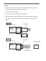
First strip
•
Place the ribbon fiber in the removable Oxford ribbon fiber clip so that a length of
20mm of coating protrudes beyond the end of the clip:
•
Close slider on thermal stripper
•
Place fiber in clip in thermal stripper and close both lids
•
Fully strip exposed coating by pressing down on both sides of stripper and pulling
apart slider. A high closing force is required to ensure that the coating strips off
cleanly.
BEFORE
Clip lid
Body of clip
AFTER
Clip lid
Coated fiber
20mm
Coated fiber
Stripped coating
Stripped fibers
11
Second (window) strip
• Reposition stripped fiber in clip so that approximately 30mm of ribbon fiber protrudes
from the clip, including about 13mm of remaining coating (assuming a final cleave
length of 10mm)
13mm
•
Replace clip in stripper (slider closed)
•
Place stripper (and clip with fiber) in stretching rig.
•
Operate the stripper by pulling the slider of the stripper as far as possible so that it
hits the end of the operating rig (if used) - a distance of about 10-12mm. When
stripping, squeeze top and bottom together to ensure coating is cut and stripped
•
Remove clip from stripper and rig
•
Remove coating sleeve from stripping tool and close top and stretcher
Window stripped
fibers
Coating glove
12
o
o
Window stripped fibers
The 90°C temperature of the stripper breaks the bond between the coating
and the fibers, but after cooling, the bond between the partially-stripped
coating glove and the fibers is partly reformed. Therefore, the fibers in the
ribbon can be clamped by clamping the coating glove. When the
unstripped portion of the coating is also clamped, the fibers can be
tensioned, sheared and cleaved.
For a desired 10mm cleave length, the window-stripped portion of the
fibers should about 13mm long. For a 7mm cleave length the stripped
portion should be about 10mm long.
Possible problems with window stripped fibers
1. Problem: The coating does not move as a tube
Solution: The coating is not hot enough so leave longer for the stripper
to heat up or use easy-strip coated fiber.
2. Problem: The coating slips out of the clip and does not strip
Solution: The clamping force of the clip is not high enough, so press
down on both parts of stripper to ensure closing force on clip
3. Problem: The coating buckles the fiber in second strip
Solution: During stripping pull the slider of the stripper parallel to the
axis of the fibers, i.e. along the rails of the jig
Summary
o The window-stripped fiber ribbon should be stripped neatly and all
fibers should be straight with no buckling.
1.5.2
Clamping
o
o
The window stripped fiber in the movable clip is placed in the cleaver. The
right-hand, fixed clip is open to accept the fiber.
The movable clip is magnetically driven against a stop and the coating
glove enters the fixed clip. Close the fixed clip so that the stripped fiber is
clamped at two points and the fixed clip clamps on the coating glove.
Possible problems with clamping stripped fibers
1. Problem: The fibers are not straight between the clamps
Solution: Window stripped fibers are not straight. Cut off the coating
glove and repeat
13
1.5.3
o
o
o
o
Cleaving
Close the top of the cleaver, pushing down on the green handle. The
green handle closes the top half of the cleaver (black anodized portion)
which also carries the anvil.
The anvil contacts the fiber, displacing it by about 0.75mm, until the top
half of the cleaver (and the anvil) reaches a stop against a silver M3
screw.
Continue to push down on the green handle.
The blade moves at a glancing angle until it touches the deflected fibers.
Because the fibers are deflected by the anvil and therefore tensioned, the
scratched fibers cleave, cleaving at an angle because of the shear. A
slight noise is heard (and felt) as the fibers cleave. All of the fibers cleave
at approximately the same time.
Cleaving principles
o
The correct amount of tension (approximately 2N in each fiber) is required
to achieve a good quality cleave. The tension is achieved by deflecting
the fibers with the anvil. A set cleave length (given by the position of the
clamp stop) therefore requires a set deflection of the fibers by the anvil to
achieve an optimum tension but the amount the fiber is deflected also
determines the cleave angle. Each tool is factory-set to produce a set
cleave length and a set cleave angle. The user can only carry out only a
small adjustment of cleave length.
1.5.4
o
Cleave Angle
The cleave angle is preset in the factory to give an 8° cleave across each
fiber core.
Removing the cleaved fibers
o
Release the green handle and the top of the tool will open automatically.
o
Remove the movable clip from the cleaver and release the cleaved fibers
from the clip.
o
Open the fixed clip to reveal the coating glove and 4 off-cut fibers.
Remove with tweezers.
o
NOTE: Do not touch the diamond with metal tweezers.
14
1.5.5
Adjustments
Cleave Length
o
The cleave length is set by the distance between the end of the coating
and the diamond blade. When the stripped fiber is transferred to the
cleaver in the movable clip, the cleave length is set by the distance
between the end of the coating (dependent on manufacturer of stripper)
and the diamond blade.
o The cleave length is preset in the factory. Cleave lengths in the
range of 5-15mm can be set. The movable clip is magnetically
driven against a metal stop (6mm in diameter with a screwdriver slot
on top).
1.5.6
Cleave Variability
•
The F-RCL-8-4F and F-RCL-8-8F have a variation in end angle of
up to +/-1° for each fiber in the fiber ribbon.
•
The variation of length of cleaved fiber ends within the fiber ribbon
is around 25µm.
15
1.6
Maintenance
o The cleavers should be kept clean and free of dust and fiber
off-cuts at all times. The cleaver should be transported in its
carrying case.
o All stripped fibers should be cleaned with an alcohol wipe
prior to insertion into the cleaver to prevent dirt accumulating
under the clamping surfaces which may break fibers.
o The diamond blade wears with time. A maintenance
schedule should be agreed with the operators in advance and
the blade should be changed after a certain number of
cleaves have been carried out or a certain amount of time
has elapsed.
o Caution: Any hard or contaminated cleaning implement may
damage the sharp edge of the diamond blade.
1.6.1
Diamond Blade
o The cleaver is not designed to have an adjustable blade. The
blade scratches the 4 fibers over a length of 1mm and
because the length of the blade is only 1.6mm, no
significantly adjustment can be made. Therefore the
hexagonal screw on the front of the body of the cleaver
should not be used to change the position of the blade.
16
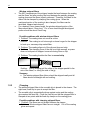
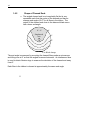
1.6.2
Shape of Cleaved Ends
o The angled cleaved end is not completely flat but is very
repeatable such that the centre of the cleaved end has an
average end angle of 8.0o for all fibers in the ribbon. The
region of the cleaved end close to the diamond blade score
has a lower end angle.
8° - 9°
Singlemode
core
8°
6°
4°
2°
Blade damage
The end angle is measured by mounting the cleaved fibers under a microscope
and tilting over at 8° so that the angled cores are horizontal. An interference lens
is used to obtain Newton rings to measure the deviation of the cleaved end away
from 8°.
Each fiber in the ribbon is cleaved at approximately the same end angle
0
17
2
0 Factory Service Information
2.1
Service Form
Newport Corporation
U.S.A. Office: 800-222-6440
FAX: 949/253-1479
Name_________________________________
Return Authorization # _________________________
(Please obtain RA# prior to return of item)
Company ___________________________________________________________________________
Address ______________________________
Date _______________________________________
Country _______________________________
Phone Number _______________________________
P.O. Number ___________________________
FAX Number _________________________________
Item(s) Being Returned:
Model # _______________________________
Serial # _____________________________________
Description __________________________________________________________________________
___________________________________________________________________________________
___________________________________________________________________________________
___________________________________________________________________________________
___________________________________________________________________________________
___________________________________________________________________________________
Reason for return of goods (please list any specific problems):
___________________________________________________________________________________
___________________________________________________________________________________
___________________________________________________________________________________
___________________________________________________________________________________
___________________________________________________________________________________
___________________________________________________________________________________
___________________________________________________________________________________
___________________________________________________________________________________
___________________________________________________________________________________
Notes: ______________________________________________________________________________
18
___________________________________________________________________________________
___________________________________________________________________________________
___________________________________________________________________________________
___________________________________________________________________________________
___________________________________________________________________________________
___________________________________________________________________________________
___________________________________________________________________________________
___________________________________________________________________________________
___________________________________________________________________________________
___________________________________________________________________________________
___________________________________________________________________________________
___________________________________________________________________________________
___________________________________________________________________________________
___________________________________________________________________________________
___________________________________________________________________________________
___________________________________________________________________________________
___________________________________________________________________________________
___________________________________________________________________________________
___________________________________________________________________________________
___________________________________________________________________________________
___________________________________________________________________________________
___________________________________________________________________________________
___________________________________________________________________________________
___________________________________________________________________________________
___________________________________________________________________________________
___________________________________________________________________________________
___________________________________________________________________________________
___________________________________________________________________________________
___________________________________________________________________________________
___________________________________________________________________________________
___________________________________________________________________________________
___________________________________________________________________________________
___________________________________________________________________________________
___________________________________________________________________________________
___________________________________________________________________________________
___________________________________________________________________________________
19