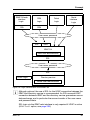
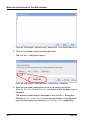
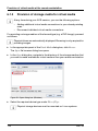
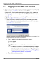
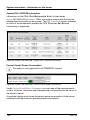
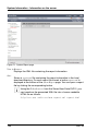
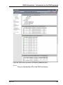
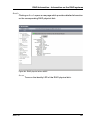
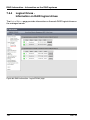
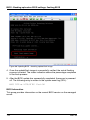
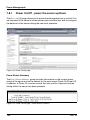
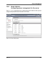
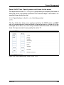
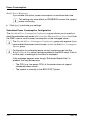
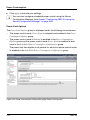
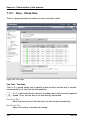
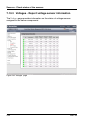
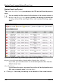
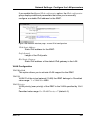
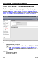
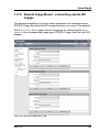
1
User Guide - English FUJITSU Software ServerView Suite Remote Management iRMC S4 - integrated Remote Management Controller Edition August 2015 Comments… Suggestions… Corrections… The User Documentation Department would like to know your opinion of this manual. Your feedback helps us optimize our documentation to suit your individual needs. Feel free to send us your comments by e-mail to [email protected]. Certified documentation according to DIN EN ISO 9001:2008 To ensure a consistently high quality standard and user-friendliness, this documentation was created to meet the regulations of a quality management system which complies with the requirements of the standard DIN EN ISO 9001:2008. cognitas. Gesellschaft für Technik-Dokumentation mbH www.cognitas.de Copyright and Trademarks Copyright © 2015 Fujitsu Technology Solutions GmbH. All rights reserved. Delivery subject to availability; right of technical modifications reserved. All hardware and software names used are trademarks of their respective manufacturers. Contents 1 Preface . . . . . . . . . . . . . . . . . . . . . . . . . . . . . 13 1.1 Purpose and target groups of the manual . . . . . . . . . . 15 1.2 Functions of the iRMC S4 (overview) . . . . . . . . . . . . . 16 1.3 User interfaces of the iRMC S4 . . . . . . . . . . . . . . . . 23 1.4 Font panel LEDs controlled by the iRMC 1.5 Communication protocols used by the iRMC 1.6 IPMI - technical background . . . . . . . . . . . . . . . . . . 26 1.7 DCMI (Data Center Management Interface) 1.8 Changes since the previous versions of the manual . . . . 34 1.9 ServerView Suite link collection . . . . . . . . . . . . . . . . 35 1.10 Documentation for ServerView Suite . . . . . . . . . . . . . 36 1.11 Notational conventions 2 Logging on to the iRMC S4 for the first time . . . . . . . . . 39 2.1 Requirements . . . . . . . . . . . . . . . . . . . . . . . . . . 39 2.2 iRMC S4 factory defaults 2.3 Logging into the iRMC S4 web interface . . . . . . . . . . . 41 3 Configuring the iRMC S4 3.1 3.1.1 3.1.1.1 3.1.1.2 Configuring the LAN interface of the iRMC S4 . . . . . . . Prerequisites . . . . . . . . . . . . . . . . . . . . . . . . . . Connected to the correct LAN port? . . . . . . . . . . . . Interaction between the IP addresses of the iRMC and the system . . . . . . . . . . . . . . . . . . . . . . . . . . . Access from a different subnet . . . . . . . . . . . . . . . Configuring the LAN interface: Configuration tools . . . . . . Configuring the LAN interface using the UEFI setup utility . . Testing the LAN interface . . . . . . . . . . . . . . . . . . . 3.1.1.3 3.1.2 3.1.3 3.1.4 iRMC S4 . . . . . . . . . . 24 . . . . . . . . 25 . . . . . . . . . 33 . . . . . . . . . . . . . . . . . . . . 37 . . . . . . . . . . . . . . . . . . . 40 . . . . . . . . . . . . . . . . . . . 43 . 43 . 44 . 44 . . . . . 45 45 45 46 47 3.2 3.2.1 3.2.2 Configuring text console redirection via LAN using the UEFI setup utility . . . . . . . . . . . . . . . . . . . . . . . . . . . 48 Configuring text console redirection for the iRMC S4 . . . . . . . 49 Using console redirection while the operating system is running . 51 3.3 3.3.1 3.3.2 Configuring and using the serial interface of the iRMC S4 . . 53 Configuring the serial interface using of the iRMC S4 . . . . . . 53 Using the Remote Manager (Serial) interface . . . . . . . . . . 55 3.4 3.4.1 3.4.2 3.4.3 Configuring the iRMC S4 over the iRMC S4 web interface Configuring the LAN parameters . . . . . . . . . . . . . . . Configuring alerting . . . . . . . . . . . . . . . . . . . . . . Configuring text console redirection . . . . . . . . . . . . . 4 User management for the iRMC S4 . . . . . . . . . . . . . . . 59 4.1 User management concept for the iRMC 4.2 User permissions . . . . . . . . . . . . . . . . . . . . . . . . 62 4.3 4.3.1 4.3.3.4 Local user management for the iRMC S4 . . . . . . . . . . . 64 Local user management using the iRMC S4 web interface . . . . . . . . . . . . . . . . . . . . . . 64 Local user management via the Server Configuration Manager . 65 SSHv2 public key authentication for iRMC S4 users . . . . . . . 66 Creating public and private SSHv2 keys . . . . . . . . . . . 67 Loading the public SSHv2 key onto the iRMC from a file . . . 71 Configuring PuTTY and the OpenSSH client for using the public SSHv2 key . . . . . . . . . . . . . . . . . . . . . . . . . . 73 Example: Public SSHv2 key . . . . . . . . . . . . . . . . . . 78 5 Advanced Video Redirection (AVR) 5.1 Requirements: Check the AVR settings . . . . . . . . . . . . 80 5.2 5.2.1 5.2.2 5.2.3 5.2.4 5.2.5 5.2.6 Using AVR via a Java Applet . . . AVR window . . . . . . . . . . . . Using a low bandwidth . . . . . . . Parallel AVR sessions . . . . . . . "Local Monitor Off Control" function Redirecting the keyboard . . . . . . Redirecting the mouse . . . . . . . 4.3.2 4.3.3 4.3.3.1 4.3.3.2 4.3.3.3 . . . . . . . . 56 56 57 57 . . . . . . . . . . . 60 . . . . . . . . . . . . . . 79 . . . . . . . . . . . . . . . . . . . . . . . . . . . . . . . . . . . . . . . . . . . . . . . . . . . . . . . . . . . . . . . . . . . . . . . . . . . . . . . . . . . . . . . . . . . . . . . . . . . . . . . . . 82 82 83 83 86 87 89 iRMC S4 5.2.7 5.2.7.1 5.2.7.2 5.2.7.3 5.2.7.4 5.2.7.5 5.2.7.6 5.2.7.7 5.2.7.8 5.2.7.9 Menus and toolbar of the AVR window Video menu . . . . . . . . . . . . AVR window - Keyboard menu . . . AVR window - Mouse menu . . . . AVR window - Options menu . . . . AVR window - Media menu . . . . AVR window - Power Control menu AVR window - Active Users menu . AVR window - Help menu . . . . . AVR Tool bar . . . . . . . . . . . . 5.3 Using AVR via HTML5 . . . . . . . . . . . . . . . . . . . . . 109 6 Virtual Media Wizard . . . . . . . . . . . . . . . . . . . . . . 111 6.1 6.1.1 6.1.2 6.1.3 6.1.4 Provision of virtual media at the remote workstation Starting Virtual Media wizard . . . . . . . . . . . . . . Virtual Media dialog box . . . . . . . . . . . . . . . . . Provision of storage media for virtual media . . . . . . . Clearing Virtual Media connections . . . . . . . . . . . 7 iRMC web interface . . . . . . . . . . . . . . . . . . . . . . . 121 7.1 Logging into the iRMC web interface . . . . . . . . . . . . . 122 7.2 Required user permissions . . . . . . . . . . . . . . . . . . 124 7.3 Structure of the user interface 7.4 7.4.1 System Information - Information on the server System Overview - General information on the server . . . . . . . . System Component Information - Information on the server components . . . . . . AIS Connect - Configuring and using AIS Connect System Report . . . . . . . . . . . . . . . . . . . CPU Utilization History . . . . . . . . . . . . . . Network Inventory . . . . . . . . . . . . . . . . . Driver Monitor . . . . . . . . . . . . . . . . . . . 7.4.2 7.4.3 7.4.4 7.4.5 7.4.6 7.4.7 iRMC S4 . . . . . . . . . . . . . . . . . . . . . . . . . . . . . . . . . . . . . . . . . . . . . . . . . . . . . . . . . . . . . . . . . . . . . . . . . . . . . . . . . . . . . . . . . . . . . . . . . . . . . . . . . . . . . . . . . . . . . . . . . . . . . . . . . . . . . . . . . . . . . . . . . . . . . . 90 91 94 99 100 102 102 105 105 106 112 113 114 116 119 . . . . . . . . . . . . . . . . 130 . . . . . . . 133 . . . . . . . 134 . . . . . . . . . . . . . . . . . . . . . . . . . . . . . . . . . . . . . . . . . . 139 142 147 149 151 152 7.5 7.5.1 7.5.2 7.5.3 7.5.4 7.6 7.6.1 7.6.1.1 7.6.1.2 7.6.2 7.7 7.7.1 7.7.2 7.7.3 7.7.4 7.7.5 7.7.6 7.8 7.8.1 7.8.2 7.8.3 7.9 7.9.1 7.9.2 7.9.3 RAID Information - Information on the RAID systems . . . . . . . . . . . . . . 153 RAID Controller - Information on RAID controllers and associated batteries . . . . . . . . . . . . . . . . . . . . . . . . . . . . . 154 Enclosures - Information on RAID enclosures . . . . . . . . . 156 Physical Disks - Information on RAID physical disks . . . . . . 160 Logical Drives - Information on RAID logical drives . . . . . . . . . . . . . . . 162 BIOS - Backing up/restore BIOS settings, flashing BIOS . . 164 Backup/Restoration - Saving/Restoring BIOS single parameter settings to/from a file . . . . . . . . . . . . . . . . . . . . . . 164 Backup BIOS Single Parameters in ServerView® WinSCU XML format . . . . . . . . . . . . . . . . . . . . . . . . . . . . 165 Restoration BIOS Single Parameters in ServerView® WinSCU XML format . . . . . . . . . . . . . . . . . . . . . . . . . 166 BIOS - Updating BIOS via "upload from file" or via TFTP . . . 168 iRMC S4 - Information, firmware and certificates . . . . . . iRMC S4 Information - Information on the iRMC . . . . . . . . iRMC S4 Time - Time options for the iRMC S4 . . . . . . . . . Save Configuration - Save iRMC S4 Firmware Settings . . . . . . . . . . . . . . . Certificate Upload - Load the DSA/RSA Certificate and private DSA/RSA Key . . . . . . . . . . . . . . . . . . . . . . . . . . Generate a self-signed Certificate - Generate self-signed RSA Certificate . . . . . . . . . . . . . iRMC S4 Firmware Update . . . . . . . . . . . . . . . . . . . 173 174 178 181 183 190 192 Power Management . . . . . . . . . . . . . . . . . . . . . . 197 Power On/Off - power the server up/down . . . . . . . . . . . 198 Power Options - Configuring power management for the server . . . . . . . . . 203 Power Supply Info - Power supply and IDPROM data for the FRU components . . . . . . . . . . . . . . . . . . . . . . . . . . 206 Power Consumption . . . . . . . . . . . . . . . . . . . . . 207 Power Consumption Configuration - Configure power consumption of the server . . . . . . . . . . . . . . . . . . . . . . . . . . . . 208 Current Power Consumption - Show the current power consumption . . . . . . . . . . . . . 214 Power History - Show server power consumption . . . . . . . . . . . . . . . . 215 iRMC S4 7.10 7.10.1 7.10.2 7.10.3 7.10.4 7.10.5 7.11 7.11.1 7.11.2 7.11.3 7.11.4 Sensors - Check status of the sensors . . . . . . . . . . . . 219 Fans - Check fans . . . . . . . . . . . . . . . . . . . . . . . . 220 Temperature - Report the temperature of the server components . . 222 Voltages - Report voltage sensor information . . . . . . . . . . 224 Power Supply - Check power supply . . . . . . . . . . . . . . 225 Component Status - Check status of the server components . . . . . . . . . . . . . 227 System Event Log and Internal Event Log . . . . . . . . . . System Event Log Content - Show information on the SEL and the SEL entries . . . . . . . Internal Event Log - Show information on the internal event log and the associated entries . . . . . . . . . . . . . . . . . . . . . . . . . . . . . . System Event Log Configuration - Configure IPMI SEL and internal event log . . . . . . . . . . . Syslog Configuration - configure syslog forwarding for SEL and internal event log . . . . . . . . . . . . . . . . . . . . . . . . 231 232 235 238 241 7.12 Server Management Information - Configuring the server settings . . . . . . . . . . . . . . . . 245 7.13 Network Settings - Configure the LAN parameters . . . . . . . . . . Network Interface Settings - Configure Ethernet settings on the iRMC . . . . . . Ports and Network Services - Configuring ports and network services . . . . . . . Proxy Settings - Configuring proxy settings . . . . . DNS Configuration - Configuring DNS for the iRMC SNMP Generic Configuration . . . . . . . . . . . . 7.13.1 7.13.2 7.13.3 7.13.4 7.13.5 7.14 7.14.1 7.14.2 . . . . . . 250 . . . . . . 251 . . . . . . . . . . . . . . . . . . . . 258 262 264 268 Alerting - Configure alerting . . . . . . . . . . . . . . . . . . 270 SNMP Trap Alerting - Configure SNMP trap alerting . . . . . . . . . . . . . . . . . . 271 Email Alerting - Configure email alerting . . . . . . . . . . . . 273 7.15 User Management . . . . . . . . . . . . . . . . . . . . . . 7.15.1 iRMC S4 User - local user management on the iRMC . . . . 7.15.1.1 New User Configuration - Configuring a new user . . . . . 7.15.1.2 User “<name>” Configuration - User configuration (details) iRMC S4 . . . . . . . . 280 280 282 283 Directory Service Configuration (LDAP) - Configuring the directory service at the iRMC . . . . . . . . . 294 7.15.2.1 Standard LDAP groups with authorization settings on the iRMC S4 . . . . . . . . . . . . . . . . . . . . . . . . . . . 297 7.15.2.2 Configuring iRMC for Microsoft Active Directory . . . . . . 302 7.15.2.3 Configuring iRMC for Novell eDirectory / OpenLDAP / OpenDS / Open DJ . . . . . . . . . . . . . . . . . . . . . . . . . . . 307 7.15.3 Centralized Authentication Service (CAS) Configuration - Configuring the CAS Service . . . . . . . . . . . . . . . . . . . . . . . . 313 7.15.2 7.16 7.16.1 Console Redirection - Redirecting the console . . . . . . . 319 BIOS Text Console - Configure and start text console redirection . . . . . . . . . . 319 7.16.1.1 BIOS Console Redirection Options - Configure text console redirection . . . . . . . . . . . . . . 320 7.16.1.2 Text console redirection while the operating system is running . 322 7.16.2 Advanced Video Redirection - Start Advanced Video Redirection (AVR) . . . . . . . . . . . . 324 7.17 7.17.1 7.17.2 Virtual Media . . . . . . . . . . . . . . . . . . . . . . . . . . 332 Virtual Media Options - Configuring virtual media options . . . 333 Remote Image Mount - connecting remote ISO images . . . . 335 7.18 7.18.1 7.18.2 7.18.3 7.18.4 7.18.5 Lifecycle Management . . . . . . . . . . . . . . . . . . . Update Settings - Configuring general eLCM update settings Online Update - Configuring the eLCM online update . . . . Offline Update - Configuring the eLCM offline update . . . . Custom Image - Handling custom images . . . . . . . . . . PrimeCollect - Health management . . . . . . . . . . . . . 8 iRMC S4 via Telnet/SSH (Remote Manager) . . . . . . . . . . . . . . . . . . . . . . . 359 8.1 Requirements on the managed server . . . . . . . . . . . . 360 8.2 Operating Remote Manager . . . . . . . . . . . . . . . . . . 361 8.3 Overview of menus . . . . . . . . . . . . . . . . . . . . . . 362 8.4 Logging in . . . . . . . . . . . . . . . . . . . . . . . . . . . 365 8.5 Main menu of the Remote Manager . . . . . . . . . . . . . 367 8.6 Required user permissions . . . . . . . . . . . . . . . . . . 369 . . . . . . 339 340 341 346 352 356 iRMC S4 8.7 Change the password . . . . . . . . . . . . . . . . . . . . . 371 8.8 System Information - Information on the managed server . . . . . . . . . . . . . . 371 8.9 Power Management 8.10 Enclosure Information - System event log and status of the sensors . . . . . . . . . 374 8.11 Service processor - IP parameters, identification LED and iRMC S4 reset . . . . . . . . . . . . . . . . . . . . . . . . . . 378 8.12 RAID Management . . . . . . . . . . . . . . . . . . . . . . . 379 8.13 Console Redirection (EMS/SAC) - Start text console redirection . . . . . . . . . . . . . . . . . 380 8.14 Start a Command Line shell... - Start a SMASH CLP shell . . . . . . . . . . . . . . . . . . . 380 8.15 Console Logging - Redirect message output to the text console (serial) . . . . . . . . . . . . . . . . . . . . . . . . . . . . . . 381 8.16 Command Line Protocol (CLP) . . . . . . . . . . . . . . . . 383 9 Configuring iRMC S4 using the Server Configuration Manager 387 9.1 Calling the Server Configuration Manager from the ServerView Installation Manager . . . . . . . . . . . . . . . . . . . . . . 389 9.2 Calling the Server Configuration Manager from the Windows Start menu . . . . . . . . . . . . . . . . . . . . . . . . . . . 389 9.3 Calling the Server Configuration Manager from the Operations Manager . . . . . . . . . . . . . . . . . . . . . . . . . . . . . 391 10 Firmware update . . . . . . . . . . . . . . . . . . . . . . . . 395 10.1 iRMC S4 firmware (overview) . . . . . . . . . . . . . . . . . 396 10.2 Setting up the USB memory stick . . . . . . . . . . . . . . . 398 10.3 10.3.1 10.3.2 Updating firmware images . . . . . . . . . . . . . . . . . . . 401 Update via the iRMC web interface . . . . . . . . . . . . . . . 401 Update using the ServerView Update Manager . . . . . . . . . 402 iRMC S4 . . . . . . . . . . . . . . . . . . . . . . 373 10.3.3 10.3.4 10.3.5 Online update using ServerView Update Manager Express or ASP 402 Update using the operating system flash tools . . . . . . . . . 403 Update via the FlashDisk menu . . . . . . . . . . . . . . . . . 405 10.4 Emergency flash . . . . . . . . . . . . . . . . . . . . . . . . 407 10.5 Flash tools . . . . . . . . . . . . . . . . . . . . . . . . . . . 408 11 Remote installation of the operating system via iRMC S4 . 413 11.1 Installing the operating system via iRMC S4 - general procedure 414 11.2 Connecting a storage medium as Virtual Media . . . . . . . 416 11.3 Booting the managed server from ServerView Suite DVD 1 and configuring it with the Installation Manager . . . . . . . . . 418 11.4 11.4.1 11.4.2 Installing the operating system on the managed server after configuration . . . . . . . . . . . . . . . . . . . . . . . . . . 421 Installing Windows on the managed server after configuration . 421 Installing Linux on the managed server after configuration . . . 423 12 Appendix . . . . . . . . . . . . . . . . . . . . . . . . . . . . 425 12.1 IPMI OEM Commands supported by the iRMC 12.1.1 Overview . . . . . . . . . . . . . . . . . . . . . 12.1.2 Description of the IPMI OEM commands . . . . . 12.1.2.1 Description format . . . . . . . . . . . . . . . 12.1.2.2 SCCI-compliant Power On/Off commands . . 12.1.2.3 SCCI-compliant communication commands . 12.1.2.4 SCCI-compliant signaling command . . . . . 12.1.2.5 Firmware-specific commands . . . . . . . . . 12.1.2.6 BIOS-specific commands . . . . . . . . . . . 12.1.2.7 iRMC S4-specific commands . . . . . . . . . . . . . . . . . . . . . . . . . . . . . . . . . . . . . . . . . . . . . . . . . . . . . . . . . . . . . . . . . . . . . . . . . . . . . . . 425 425 427 427 428 433 435 436 440 442 12.2 Configuring the iRMC via SCCI and scripted configuration 452 12.2.1 iRMC configuration data . . . . . . . . . . . . . . . . . . . . 452 12.2.1.1 Overview . . . . . . . . . . . . . . . . . . . . . . . . . . 452 12.2.1.2 SCCI file format . . . . . . . . . . . . . . . . . . . . . . . 454 12.2.1.3 Restrictions . . . . . . . . . . . . . . . . . . . . . . . . . 458 12.2.1.4 Exporting / importing configuration data from / on the iRMC S4 459 iRMC S4 12.2.2 Scripted configuration of the iRMC . . . . . . . . . . . . 12.2.2.1 List of SCCI commands supported by the iRMC . . . . 12.2.2.2 Scripting with cURL . . . . . . . . . . . . . . . . . . 12.2.2.3 Scripting with Visual Basic (VB) Script . . . . . . . . . 12.2.2.4 Scripting with Python . . . . . . . . . . . . . . . . . . 12.2.2.5 Generating encrypted passwords with iRMC_PWD.exe 12.3 12.3.1 12.3.1.1 12.3.1.2 12.3.2 12.3.2.1 12.3.2.2 12.3.2.3 12.3.2.4 12.3.2.5 12.3.2.6 12.3.2.7 12.3.2.8 12.3.2.9 12.3.2.10 12.3.2.11 12.3.2.12 12.3.2.13 12.3.2.14 12.3.2.15 12.3.2.16 iRMC S4 . . . . . . . . . . . . . . . . . . 460 460 461 462 463 464 iRMC system report . . . . . . . . . . . . . . . . . . . . . . Scripted download and automatic evaluation of the iRMC report 467 Scripting with cURL . . . . . . . . . . . . . . . . . . . . . Scripting with Visual Basic . . . . . . . . . . . . . . . . . . Information Sections . . . . . . . . . . . . . . . . . . . . . . . List of supported System Report sections in the XML . . . . Summary section . . . . . . . . . . . . . . . . . . . . . . . BIOS . . . . . . . . . . . . . . . . . . . . . . . . . . . . . Processor . . . . . . . . . . . . . . . . . . . . . . . . . . Memory . . . . . . . . . . . . . . . . . . . . . . . . . . . Fans . . . . . . . . . . . . . . . . . . . . . . . . . . . . . Temperature . . . . . . . . . . . . . . . . . . . . . . . . . Power Supplies . . . . . . . . . . . . . . . . . . . . . . . . Voltages . . . . . . . . . . . . . . . . . . . . . . . . . . . IDPROMS . . . . . . . . . . . . . . . . . . . . . . . . . . SensorDataRecords . . . . . . . . . . . . . . . . . . . . . PCIDevices . . . . . . . . . . . . . . . . . . . . . . . . . . SystemEventLog . . . . . . . . . . . . . . . . . . . . . . . InternalEventLog . . . . . . . . . . . . . . . . . . . . . . . BootStatus . . . . . . . . . . . . . . . . . . . . . . . . . . ManagementControllers . . . . . . . . . . . . . . . . . . . 467 . . 467 468 469 469 469 470 471 471 472 472 473 473 474 474 474 474 475 475 476 1 Preface Modern server systems are becoming increasingly complex. The requirements with respect to the management of such systems are growing accordingly. In response to this development, a number of vendors founded the “Intelligent Platform Management Interface” (IPMI) initiative with the objective of defining a standardized, abstract, message-based interface between the central system controller (Baseboard Management Controller - BMC) and intelligent hardware for platform management. For further details on IPMI, please refer to section "IPMI - technical background" on page 26. The integrated Remote Management Controller iRMC represents a BMC with integrated LAN connection and extended functionality. In this way, the iRMC offers comprehensive control over PRIMERGY servers, irrespective of the system status. In particular, the iRMC allows for out-of-band management (Lights Out Management, LOM) of PRIMERGY servers. Out-of-band management uses of a dedicated management channel that enables a system administrator to monitor and manage servers via remote control regardless of whether the server is powered on. Figure 1: iRMC S4 on the system board of a PRIMERGY server iRMC S4 13 Preface As an autonomous system on the system board of a modern PRIMERGY server, the iRMC has its own operating system, its own web server, separate user management and independent alert management. The iRMC remains powered up even when the server is in stand-by mode. Beyond making it possible to manage a PRIMERGY server out-of-band, the enhanced functionality of the newest version of the iRMC, which comes with an integrated SD card, allows for comprehensive lifecycle management of a PRIMERGY server. As life cycle management is largely integrated ("embedded") in and entirely controlled by the iRMC, it is called "embedded Life Cycle Management (eLCM)". Some eLCM functions require the iRMC to communicate and cooperate with the ServerView Agentless Service running on the managed server. Communicating with the ServerView Agentless Service also provides the iRMC S4 with additional in-band information. This manual describes how to configure the iRMC and the various user interfaces available. 14 iRMC S4 Purpose and target groups of the manual 1.1 Purpose and target groups of the manual This manual is aimed at system administrators, network administrators, and service staff who have a sound knowledge of hardware and software. It provides basic information on the technology behind IPMI and deals with the following aspects in detail: ● Logging on to the iRMC ● Configuring the iRMC ● User management on the iRMC ● Advanced Video Redirection via iRMC ● Virtual Media via iRMC ● iRMC web interface ● Telnet/SSH-based interface (Remote Manager) of the iRMC ● Configuring the iRMC with the Server Configuration Manager ● Updating the firmware ● Remote installation of the operating system via iRMC ● Appendix IPMI OEM Commands – IPMI OEM Commands – Configuring the iRMC via SCCI and scripted configuration Service If you have any further questions on remote management for PRIMERGY servers, contact the service and support partners responsible for you. Other information http://www.ts.fujitsu.com iRMC S4 15 Functions of the iRMC S4 1.2 Functions of the iRMC S4 (overview) The iRMC supports a wide range of functions that are provided by default. With Advanced Video Redirection (AVR) and Virtual Media, the iRMC also provides two additional advanced features for the remote management of PRIMERGY servers. To use AVR, virtual Media and embedded Lifecycle Management (eLCM), you require a valid license key, which can be purchased separately. Standard functions of the iRMC S4 ● Browser access The iRMC features its own web server which can be accessed by the management station from a standard web browser. ● Security (SSL, SSH) Secure access to the Web server and secure graphical console redirection including mouse and keyboard can be provided over HTTPS/SSL. An encrypted connection protected using SSH mechanisms can be set up to access the iRMC using the Remote Manager. The Remote Manager is an alphanumeric user interface for the iRMC. ● ServerView Integration The ServerView agents detect the iRMC and automatically assign it to the relevant server. This means that it is possible to start the iRMC web interface and text console redirection using the ServerView Remote Management Front end directly from ServerView Operations Manager. Communication between the iRMC and the ServerView Agentless Service (as of ServerView Operations Manager 7.0) allows for enhanced out-ofband management of PRIMERGY servers. ● Power management Irrespective of the status of the system, you have the following options for powering the managed server up or down from the remote workstation – using the iRMC web interface – using the Remote Manager and the command line interface (CLP) – with a script. 16 iRMC S4 Functions of the iRMC S4 ● Power consumption control The iRMC allows comprehensive power consumption control on the managed server. In addition, you can specify the mode (minimum power consumption or maximum performance) that the iRMC uses to control power consumption on the managed server. You can switch between these modes as required. ● Customer Self Service (CSS) Summary tables for the server components, sensors and the power supply on the iRMC web interface provide information in a separate column as to whether the server component affected is a CSS component or not. In addition, error list of the system event log (SEL) shows for every event whether it has been triggered by a CSS component. ● Text console redirection You can start a Telnet/SSH session to the iRMC from the ServerView Remote Management Front end. This calls the Remote Manager, via which you can start a text console redirection session. ● Basic functions of a BMC The iRMC supports the basic functions of a BMC such as voltage monitoring, event logging and recovery control. ● “Headless” system operation The managed server does not require a mouse, monitor or keyboard to be connected. The benefits of this include lower costs, far simpler cabling in the rack and increased security. ● Identification LED To facilitate identification of the system, for instance if it is installed in a fully populated rack, you can activate the identification LED from the iRMC web interface. ● Global error LED A global error LED informs you of the status of the managed system at all times and at the same time shows the CSS (Customer Self Service) status. ● Power LED The power LED informs you whether the server is currently switched on or off. iRMC S4 17 Functions of the iRMC S4 ● S5 LED The S5 LED informs you on the power status of the server. ● CIM support The iRMC supports CIM-XML, WS-Man, and SMASH CLP (System Management Architecture for Server Hardware Command Line Protocol). ● LAN On some systems, the LAN interface of the fitted system NIC (Network Interface Card) on the server is reserved for the management LAN. On other systems, you have the option of configuring this LAN interface to – reserve it for the management LAN – set it up for shared operation with the system or – make it completely available to the system. The ports marked with a wrench symbol are assigned to the iRMC (see figure 7 on page 44). ● Network Bonding Network bonding for the iRMC is designed for redundancy in the event of Ethernet network adapter failures. Thus, iRMC network management traffic is protected from loss of service which occurs due to failure of a single physical link. The iRMC supports the active-backup mode, i. e. one port is active until the link fails, then the other port takes over the MAC and becomes active. ● SNMPv1/v2c/v3 support You can configure an SNMP service on the iRMC which supports SNMPv1/v2c/v3 GET requests on SNMP SC2 MIB (Sc2.mib), SNMP MIB2, SNMP OS.MIB, and SNMP STATUS.MIB. When the SNMP service is enabled, information on devices such as fans, temperature sensors etc. are available via the SNMP protocol and can be viewed on any system running an SNMP Manager. ● Command line interface (CLP) In addition to the Remote Manager, the iRMC also supports SMASH CLP as standardized by the DMTF (Distributed Management Task Force). 18 iRMC S4 Functions of the iRMC S4 ● Simple configuration - interactive or script-based The following tools are available for configuring the iRMC: – iRMC web interface – Server Configuration Manager – UEFI BIOS Setup It is also possible to carry out configuration with the Server Configuration Manager or IPMIVIEW using scripts. This means that it is possible to configure the iRMC when the server is first configured via ServerView Installation Manager. It is also possible to configure a large number of servers on the basis of scripts. ● Support for the LocalView service panel If PRIMERGY servers are equipped with a ServerView local service panel, this module allows you to determine what module is faulty and whether you can replace the faulty module yourself. ● Local user management The iRMC has its own user management function which allows up to 16 users to be created with passwords and to be assigned various rights depending on the user groups they belong to. ● Global user management using a directory service The global user IDs for the iRMC are stored centrally in the directory service's directory. This makes it possible to manage the user identifications on a central server. They can therefore be used by all the iRMCs that are connected to this server in the network. The following directory services are currently supported for iRMC user management: – – – – ● Microsoft® Active Directory Novell® eDirectory OpenLDAP OpenDS CAS-based single sign-on (SSO) authentication The iRMC supports Centralized Authentication Service (CAS) configuration, which allows you to configure the iRMC web interface for CAS-based single sign-on (SSO) authentication. iRMC S4 19 Functions of the iRMC S4 The first time a user logs in to an application (e.g. the iRMC web interface) within the SSO domain of the CAS service, they are prompted for their credentials by the CAS-specific login screen. Once they have been successfully authenticated by the CAS service, the user is granted access to the iRMC web interface as well as to any other service within the SSO domain without being prompted for login credentials again. ● DNS / DHCP The iRMC provides support for automatic network configuration. It has a default name and DHCP support is set by default so that the iRMC S4 gets its IP address from the DHCP server. The iRMC name is registered by the Domain Name System (DNS). Up to five DNS servers are supported. If DNS/DHCP is not available, the iRMC also supports static IP addresses. ● Power supply The iRMC is powered by the standby supply of the system. ● Alert management The alert management facility of the iRMC provides the following options for forwarding alerts (alerting): – Platform Event Traps (PET) are sent via SNMP. – Direct alerting by email. In addition, the iRMC provides the ServerView agents with all the relevant information. ● Read, filter and save the system event log (SEL). You can view, save and delete the contents of the SEL – by using the iRMC web interface or – by using the Telnet/SSH-based interface (Remote Manager) of the iRMC S4. ● Read, filter and save the internal event log (iEL). You can view, save and delete the contents of the iEL – by using the iRMC web interface or – by using the Telnet/SSH-based interface (Remote Manager) of the iRMC S4. 20 iRMC S4 Functions of the iRMC S4 ● UEFI support Unified Extensible Firmware Interface (UEFI) is a specification for a software program that connects a computer's firmware to its operating system. UEFI has a firmware validation process, called secure boot. Secure boot defines how platform firmware manages security certificates, validation of firmware, and a definition of the interface (protocol) between firmware and the operating system. Extended functionality of the iRMC S4 Alongside the standard functionality, the iRMC also supports the Advanced Video Redirection, Virtual Media functions, and embedded Lifecycle Management (eLCM). ● Advanced Video Redirection (AVR) The iRMC supports Advanced Video Redirection which offers the following benefits: – Operation over a standard web browser. No additional software needs to be installed in the management station other than the Java Runtime Environment. – System-independent graphical and text console redirection (including mouse and keyboard). – Remote access for boot monitoring, BIOS administration and operation of the operating system. – AVR supports up to two simultaneous “virtual connections” for working on a server from a different location. It also reduces the load on the network by using hardware and video compression. – Local monitor-off support: It is possible to power down the local screen of the managed PRIMERGY server during an AVR session in order to prevent unauthorized persons from observing user input and actions carried out on the local server screen during the AVR session. – Low bandwidth In the case of a reduced data transfer rate, you can configure a lower bandwidth (bits per pixel, bpp) in terms of color depth for your current AVR session. iRMC S4 21 Functions of the iRMC S4 ● Virtual Media The Virtual Media functionality makes a “virtual” drive available which is physically located on a remote workstation or made available centrally on the network using the Remote Image Mount functionality. The “virtual” drives available with Virtual Media are simply managed in much the same way as local drives and offer the following options: – – – – Read and write data. Boot from Virtual Media. Install drivers and small applications. Update BIOS from remote workstation. (BIOS update via USB) Virtual Media supports the following device types to provide a “virtual drive” on the remote workstation: – – – – – – – – CD ROM DVD ROM Memory stick Floppy image CD ISO image DVD ISO image Physical Harddisk Drive HDD ISO image The Remote Image Mount functionality provides ISO images centrally on a network share in the form of a “virtual drive”. ● Embedded Lifecycle Management (eLCM) The embedded Lifecycle Management (eLCM) solution allows you to control lifecycle management of PRIMERGY servers with a few mouse clicks centrally from the iRMC web interface without the need of handling with physical devices. eLCM comprises the following functions: – eLCM update management – eLCM image management (Custom Image) – eLCM health management (PrimeCollect) For details see the manual "ServerView embedded Lifecycle Management (eLCM)". 22 iRMC S4 Communication interfaces of the iRMC S4 1.3 User interfaces of the iRMC S4 The iRMC provides the following communication interfaces: ● iRMC S4 web interface (web interface) The connection to the iRMC web server is established over a standard web browser (e.g. Microsoft Internet Explorer, Mozilla Firefox). Among other things, the web interface of the iRMC provides you with access to all system information and data from the sensors such as fan speeds, voltages, etc. You can also configure text-based console redirection and start graphical console redirection (Advanced Video Redirection, AVR). In addition, administrators can fully configure the iRMC over the web interface. Secure access to the iRMC web server can be provided with HTTPS/SSL. Operation of the iRMC over the web interface is described in chapter "iRMC web interface" on page 121. ● Remote Manager: Text-based Telnet/SSH interface via LAN You can call the Remote Manager – from the ServerView Remote Management Frontend, – directly from a Telnet/SSH client. The alphanumeric user interface of the Remote Manager provides you with access to system and sensor information, power management functions and the error event log. In addition, you can launch text console redirection or a SMASH CLP shell. If you call the Remote Manager over SSH (Secure Shell), the connection between the Remote Manager and the managed server is encrypted. Operation of the iRMC using the Remote Manager is described in chapter "iRMC S4 via Telnet/SSH (Remote Manager)" on page 359. ● Remote Manager (Serial): Text-based serial interface over Serial 1 The Remote Manager (serial) interface is identical to the Remote Manager interface. iRMC S4 23 Communication interfaces of the iRMC S4 1.4 Font panel LEDs controlled by the iRMC The iRMC controls the status LEDs which are located on the front panel of the server. The LEDs and the layout of how they are arranged differ depending on the server type. Status LEDs on the front panel (Nexperience design): Status of the Server LED on the Server S5 LED (green) Power LED (green) AC-OFF off off S5 (shutdown) on off S0 (power on) off on S3 (sleep mode) off blinking with 1Hz (BIOS controlled) iRMC not ready on blinking with 0,5 Hz (iRMC controlled) Power-on Delay on on Status LEDs on the front panel (legacy design): 24 Status of the Server Power LED on the Server AC-OFF off S5 (shutdown) orange S0 (power on) green S3 (sleep state) blinking green with 1Hz (BIOS controlled) iRMC not ready blinking alternately in orange/green with 1 Hz (iRMC controlled) Power-on Delay yellow iRMC S4 Communication protocols used by the iRMC S4 1.5 Communication protocols used by the iRMC The communication protocols and ports used by the iRMC are shown in table 1. Remote side of the connection Communication iRMC side of the direction connection (port no. / protocol) 623/UDP 623/UDP 80/TCP 80/TCP 443/TCP 443/TCP 3172/TCP 3172/TCP SSH 22/TCP 22/TCP SNMP (general mess.) 161/UDP 161/UDP SNMP Trap LDAP RMCP Configurable Enabled by default no yes yes yes yes yes yes no yes yes no no 162/UDP no yes 389/TCP/UDP yes no 389/TCP/UDP 636/TCP/UDP yes no 636/TCP/UDP Email / SMTP 25/TCP yes no 25/TCP CIM 5988/CIM-XML 5989/CIM-XML 80/WS-MAN 80/WS-MAN HTTP port HTTPs port Telnet LDAP SSL Table 1: Communication protocols and ports used by the iRMC iRMC S4 25 IPMI - technical background 1.6 IPMI - technical background The iRMC makes the BMC functions available over the IPMI interface. Intelligent Platform Management The “Intelligent Platform Management” initiative is a response to the increasing complexity of modern server systems. A number of manufacturers have joined this initiative in order to come up with a new solution for monitoring these server systems. The term “Intelligent Platform Management” expresses the core aspect of this approach to the solution: Functions for monitoring and recovery of systems are implemented directly in the hardware and firmware for platform management. Objective The objective was to define a standardized, abstract and message-based interface between the central system controller (Baseboard Management Controller - BMC) and intelligent platform management hardware. The standardization committees combined the central characteristics of various platform management modules into standardized descriptions. Definition The IPMI specification defines: “IPMI is a hardware level interface specification that is ‘management software neutral’ providing monitoring and control functions that can be exposed through standard management software interfaces such as DMI, WMI, CIM, SNMP, etc. As a hardware level interface, it sits at the bottom of a typical management software stack” [see section "IPMI and other management standards" on page 27]. Advantage The IPMI specifications ensure the independence of functions for inventory, logging, recovery and monitoring of a system by the system processor, BIOS or operating system. This means that a system can still be involved in platform management when it is shut down and turned off. 26 iRMC S4 IPMI - technical background IPMI and other management standards IPMI is best used in conjunction with system management software running under the relevant operating system. Integration of the IPMI functionality into the management functionality offered by a management application and the operating system results in a powerful platform management environment. An overview of the relationship between IPMI and the management software stack is shown by figure 2: Figure 2: IPMI in the management software stack (source: IPMI specification, see section "References" on page 33) IPMI, IPMB and ICMB The IPMI initiative resulted in three central standards: – IPMI. Intelligent Platform Management Interface Specification describes the higher-level architecture, the current commands, event formats, data packets and properties that are used in IPMI-based systems. – IPMB. Intelligent Platform Management Bus is an I2C based (write only) bus, which provides a standardized connection between various modules in a common housing. IPMB can also be used as a standardized interface for remote management modules. iRMC S4 27 IPMI - technical background – ICMB. Intelligent Chassis Management Bus (Not currently implemented in the ServerView remote management environment.) provides a standardized interface for exchange of platform management information and for control across systems. ICMB is designed in such a way that it can be implemented with a device that is connected to the IPMB. IPMI implementation The core element of an IPMI implementation is the Baseboard Management Controller (BMC). The BMC performs the following tasks: – The BMC organizes the interface between the system management software and the platform management hardware. – It provides autonomous functions for monitoring, event logging and recovery control. – The BMC acts as a gateway between the system management software and IPMB. IPMI allows platform management to be extended: Additional management controllers can be connected via the IPMB. The IPMB is an I2C based serial bus, which runs between the main modules of the system. It is used for communication with and between the management controllers. With the support of multiple management controllers, IPMI provides a scalable architecture: A complex server system can use multiple controllers for monitoring different subsystems, e.g. power supplies, hot swap RAID drive modules etc. In addition, IPMI provides ‘low level’ I2C commands, which can be accessed via a management controller connected to the IPMB on 'unintelligent' I2C modules that cannot process IPMI commands. An overview of the fundamental elements of an IPMI implementation is available in figure 3 on page 29. 28 iRMC S4 IPMI - technical background Figure 3: IPMI block diagram (source: IPMI specification, see section "References" on page 33) iRMC S4 29 IPMI - technical background IPMI and “in band” and “out of band” management In the field of system management, a distinction is made between “in-band” and “out-of-band” management: – The term “in-band” management is used when the operating system is running on the managed server. – The term “out-of-band” management is used when the operating system is not running on the managed server, for instance if the hardware is faulty. As different interfaces are available in an environment with IPMI compatible systems, you can manage IPMI compatible systems either “in band” or “out of band”. IPMI-over-LAN “IPMI-over-LAN” is the current name for the specification of the LAN interface in the IPMI standard. This specification stipulates how IPMI messages can be sent to or from the BMC of a managed system - encapsulated in RMCP (Remote Management Control Protocol) data packets. These RMCP data packets are transferred via an Ethernet LAN connection using the UDP (User Datagram Protocol) under IPv4 (Internet Protocol Version 4). The RMCP protocol has been specified to support the management of system statuses in which the operating system is not running. The RMCP is a simple inquiry/response protocol. The interface for such a connection is provided on an onboard LAN controller assigned to the BMC. I The interface can only be provided by an on-board LAN controller, not by an inserted LAN card. 30 iRMC S4 IPMI - technical background Of the two ports that RCMP uses under UDP, the BMC communicates with the LAN controller via port 623 (primary RMCP Port). Figure 4: BMC and LAN controller Serial Over LAN interface (SOL) “Serial Over LAN” is an interface compliant with the IPMI V2.0 standard, which controls transfer of serial data over a LAN connection. In particular, SOL specifies the packet formats and protocols for transferring serial data streams over a LAN between the serial controller on the managed computer and a remote workstation. SOL is based on the IPMI-over-LAN specification. In order to establish an SOL connection, a remote management application first initiates an IPMI-over-LAN session with the BMC. After this has been done, the SOL services can be activated from the remote workstation. The data traffic between the serial controller and the remote workstation is handled over the same IPMI session as the IPMI commands. As soon as an SOL connection has been established, data transfer between the serial controller and the remote workstation is carried out as follows: – Transfer from the serial controller to the remote workstation: The data stream issued by the serial controller is partitioned by the BMC, packaged and then sent to the remote workstation over the LAN. – Transfer from the remote workstation to the serial controller: BMC unpacks the characters contained in the packages sent by the remote workstation and forwards them to the serial controller as a character stream. iRMC S4 31 IPMI - technical background Figure 5: BMC and SOL The SOL character data is then exchanged between the BMC of the managed system and the remote workstation as SOL messages. The SOL messages are encapsulated in RMCP+ data packets and transferred in UDP datagrams over an Ethernet LAN connection using IPv4 (Internet Protocol Version 4). The RMCP+ protocol is based on the RMCP protocol, but includes extensions for encryption, authentication, etc. Serial over LAN permits “headless” management by console redirection by both the BIOS and the operating system of the managed server. High-cost concentrator solutions are not required. Channel concept under IPMI ‘Channels’ provide the mechanisms with which IPMI messages are routed to the BMC via various connection carriers. Up to nine channels can be supported. The system interface and the primary IPMB are fixed. The other seven channels are available for the implementation. Channels can be either ‘session based’ or ‘sessionless’. The ‘session’ concept has two meanings: It is either a concept for user authentication (see the section "User identifications" on page 33) or a concept for routing multiple IPMI message streams via a single channel. Examples of ‘session based’ channels are LAN channels or serial / modem channels. Examples of ‘sessionless’ channels are the system interface and the IPMB. 32 iRMC S4 Data Center Management Interface (DCMI) User identifications For ‘session based’ channels (see the section "Channel concept under IPMI" on page 32), a user login is necessary. By contrast, the ‘sessionless’ channels have no user authentication. Under IPMI, the user configuration is channel specific. Thus, users can have different privileges depending on whether they are accessing the BMC via the LAN channel or the serial channel. References Information about the IPMI standards can be found on the Internet: http://developer.intel.com/design/servers/ipmi/index.htm 1.7 DCMI (Data Center Management Interface) The iRMC supports the DCMI (Data Center Management Interface) protocol, which is compliant with the IPMI V2.0 standard. DCMI has been designed to improve manageability and energy efficiency of server systems that are deployed in large data centers. To meet the hardware management requirements of servers within data centers, DCMI supports, among others, the following key features: – – – – – Inventory functions (server identification) Power Management and power monitoring Power consumption monitoring and control Event logging Temperature monitoring Detailed information about DCMI can be found on the DCMI home page: http://www.intel.com/technology/product/DCMI iRMC S4 33 Changes compared with the previous version 1.8 Changes since the previous versions of the manual This manual refers to the iRMC S4 firmware version 8.0 and replaces the following online manual: “iRMC - integrated Remote Management Controller”, April 2015 edition. The manual includes the following updates: ● iRMC web interface: – New redirection function via HTML5 parallel to the Java based redirection – New HP SIM integration – CIM support With the Common Information Model (CIM), relationship information (what's connected to what) can be used to help trace the source and status of problems. ● Extended SNMP support ● RESTful API REST (REpresentational State Transfer) is an architectural style, and an approach to communications that is often used in the development of Web services. When Web services use REST architecture, they are called RESTful APIs (Application Programming Interfaces) or REST APIs. REST architecture involves reading a designated Web page that contains an XML file. 34 iRMC S4 Changes compared with the previous version 1.9 ServerView Suite link collection Via the link collection, Fujitsu Technology Solutions provides you with numerous downloads and further information on the ServerView Suite and PRIMERGY servers. For ServerView Suite, links are offered on the following topics: ● Forum ● Service Desk ● Manuals ● Product information ● Security information ● Software downloads ● Training I The downloads include the following: – Current software versions for the ServerView Suite as well as additional Readme files. – Information files and update sets for system software components (BIOS, firmware, drivers, ServerView agents and ServerView update agents) for updating the PRIMERGY servers via ServerView Update Manager or for locally updating individual servers via ServerView Update Manager Express. – The current versions of all documentation on the ServerView Suite. You can retrieve the downloads free of charge from the Fujitsu Technology Solutions Web server. For PRIMERGY servers, links are offered on the following topics: ● Service Desk ● Manuals ● Product information ● Spare parts catalogue iRMC S4 35 Documentation for the ServerView Suite Access to the link collection You can reach the link collection of the ServerView Suite in various ways: 1. Via ServerView Operations Manager. Ê Select Help – Links on the start page or on the menu bar. This opens the start page of the ServerView link collection. 2. Via the start page of the online documentation for the ServerView Suite on the Fujitsu Technology Solutions manual server. I You access the start page of the online documentation via the following link: http://manuals.ts.fujitsu.com Ê In the selection list on the left, select x86 Servers. Ê On the right, click PRIMERGY ServerView Links under Selected documents. This opens the start page of the ServerView link collection. 3. Via the ServerView Suite DVD 2. Ê In the start window of the ServerView Suite DVD 2, select the option Select ServerView Software Products. Ê Click Start. This takes you to the page with the software products of the ServerView Suite. Ê On the menu bar select Links. This opens the start page of the ServerView link collection. 1.10 Documentation for ServerView Suite The documentation for the ServerView Suite can be downloaded free of charge from the Internet. You will find the online documentation at http://manuals.ts.fujitsu.com under the link x86 servers. 36 iRMC S4 Notational conventions 1.11 Notational conventions The meanings of the symbols used in this manual are as follows: V Warning I This symbol is used to draw attention to risks which may represent a health hazard or which may lead to data loss or damage to the hardware. This symbol is used to highlight important information and tips. Ê This symbol indicates an action which you must carry out. Text in italics In running text, commands, menu items, and the names of buttons, options, files and paths are shown in italics. <text> Indicates variables which must be replaced by current values. Monospaced font Output from the system is shown in monospaced font. Monospaced font Commands to be entered at the keyboard are Bold monospaced font shown in bold, monospaced font. [square brackets] Indicate optional entries. {braces} Indicate a list of alternatives separated by “|”. [Keyboard] [symbols] Keys are shown as they appear on the keyboard. If uppercase characters are to be entered explicitly, this is indicated for instance by [SHIFT] - [A] for A. If two keys are to be pressed simultaneously, this is indicated by a hyphen between the two keyboard symbols. Table 2: Notational conventions If reference is made to passages elsewhere in this manual, the title of the chapter or section is named and the page number given refers to the start of the section. iRMC S4 37 2 Logging on to the iRMC S4 for the first time The factory default settings of the iRMC allow you to log in to the iRMC S4 for the first time without the need for any configuration activities. 2.1 Requirements On the remote workstation: – Windows: Internet Explorer as of Version 10.x. Linux: Mozilla Firefox 3.x. – For console redirection: Sun Java Virtual Machine Version 1.6 or higher. In your network: – You must have a DHCP server in your network. – If you want to log in with a symbolic name rather than an IP address at the iRMC web interface, the DHCP server in your network must be configured for dynamic DNS. – DNS must be configured. Otherwise you must ask for the IP address. iRMC S4 39 iRMC S4 factory defaults 2.2 iRMC S4 factory defaults The firmware of the iRMC provides a default administrator ID and a default DHCP name for the iRMC. Default administrator ID: Administrator ID: admin Password: admin I Both the administrator ID and the password are case-sensitive. For reasons of security, it is recommended that you create a new administrator account once you have logged in, and then delete the default administrator account or at least change the password for the account (see section "User Management" on page 280). Default DHCP name of the iRMC S4 The default DHCP name of the iRMC uses the following pattern: IRMC<SerialNumber> I The serial number corresponds to the last 3 bytes of the MAC address of the iRMC. You can take the MAC address of the iRMC from the label on your PRIMERGY server. After you have logged in, the MAC address of the iRMC can be found as a read-only entry above the fields on the page Network Interface (see page 251). 40 iRMC S4 Logging into the iRMC S4 web interface 2.3 Logging into the iRMC S4 web interface Ê Open a web browser on the remote workstation and enter the DNS name or IP address of the iRMC. I You can take the DNS name of the iRMC from the label on your PRIMERGY server. The following login prompt appears: Figure 6: Login prompt for the iRMC S4 web interface I If the login prompt does not appear, check the LAN connection (see section "Testing the LAN interface" on page 47). Ê Type in the data for the default administrator account. User name: admin Password: admin Ê Click OK to confirm your entries. The iRMC web interface opens showing the System Information page (see page 133). iRMC S4 41 3 Configuring the iRMC S4 The following tools are available for configuring the iRMC: – UEFI setup utility (see page 46) – iRMC web interface (see page 121) – Server Configuration Manager (see page 387) This chapter provides you with information about the following topics: – Configuring the LAN interface of the iRMC using the UEFI setup utility (see page 46). – Configuring text console redirection via LAN using the UEFI setup utility (see page 48). – Configuring the serial interface of the iRMC UEFI setup utility (see page 53). – Configuring the iRMC over the web interface (for an overview, see page 56). 3.1 Configuring the LAN interface of the iRMC S4 This section describes: – Requirements for configuring the LAN interface – Configuring the LAN interface in the UEFI setup utility – Testing the LAN interface I "Spanning Tree" tree for the connection of the iRMC must be deactivated (e.g. Port Fast=enabled; Fast Forwarding=enabled). iRMC S4 43 Configuring the LAN interface of the iRMC S4 3.1.1 Prerequisites Note the following requirements with respect to configuring the IP address: – The LAN cable must be connected to the correct port. (see section "Connected to the correct LAN port?" on page 44). – Interaction between the IP addresses of the iRMC and the system (see the section "Interaction between the IP addresses of the iRMC and the system" on page 45). 3.1.1.1 Connected to the correct LAN port? The interface for a LAN connection is provided on an onboard LAN controller assigned to the iRMC (see also figure 4 on page 31). Depending on the server type, the system board of a PRIMERGY server provides two or three LAN interfaces. The ports marked with a wrench symbol are assigned to the iRMC (in figure 7, for example, these are port 1 and the top left-hand port). I Check that the LAN cable is connected to the correct port. Depending on the type of PRIMERGY server, different ports may be marked with the wrench symbol. Dedicated Service / Management LAN (port exclusively for the iRMC S4; with the iRMC S4 a LAN speed up to 1000 MBit/s is available, depending on the server hardware.) (1) (2) Shared LAN (iRMC S4 and system) LAN (port exclusively for the system) Figure 7: Ports for the iRMC S4 (indicated by wrench symbol) 44 iRMC S4 Configuring the LAN interface of the iRMC S4 3.1.1.2 Interaction between the IP addresses of the iRMC and the system The LAN controller of the PRIMERGY server requires a separate IP address for the iRMC in order to ensure that data packets are reliably transferred to the iRMC (and not to the operating system). The IP address of the iRMC must be different from that of the system (operating system). 3.1.1.3 Access from a different subnet If the remote workstation accesses the iRMC of the managed server from a different subnet and DHCP is not used, you must configure the gateway. 3.1.2 Configuring the LAN interface: Configuration tools You can configure the iRMC’s LAN interface in a number of ways: Depending on the type of the PRIMERGY server – using the UEFI setup utility (see page 46), – iRMC web interface (see section "Network Settings - Configure the LAN parameters" on page 250), – using the Server Configuration Manager (see chapter "Configuring iRMC S4 using the Server Configuration Manager" on page 387). iRMC S4 45 Configuring the LAN interface of the iRMC S4 3.1.3 Configuring the LAN interface using the UEFI setup utility You can configure the iRMC’s LAN interface using the UEFI setup utility: Ê Call the UEFI setup utility of the managed server. Do this by pressing [F2] while the server is booting. Ê Call the iRMC LAN parameter configuration menu: Server Mgmt – iRMC LAN Parameters Configuration Figure 8: iRMC LAN Parameters Configuration Menu 46 iRMC S4 Configuring the LAN interface of the iRMC S4 Ê Configure the following settings: Management LAN Set the value to Enabled. Management LAN Port The Management setting is recommended. I For details on configuring the remaining settings see section "Network Settings - Configure the LAN parameters" on page 250 and/or refer to the manual "BIOS (Aptio) Setup Utility" manual corresponding to your server. Ê Save the settings. Ê If you want to use console redirection on the iRMC, continue with section "Configuring text console redirection for the iRMC S4" on page 49. If you do not want to use text console redirection on the iRMC, exit the UEFI setup and continue with the next section "Testing the LAN interface". 3.1.4 Testing the LAN interface You can test the LAN interface as follows: Ê Use a web browser to attempt to log into the iRMC web interface. If no login prompt appears, it is probable that the LAN interface is not working. Ê Test the connection to the iRMC with a ping command. iRMC S4 47 Configuring text console redirection via LAN 3.2 Configuring text console redirection via LAN using the UEFI setup utility Text console redirection will be available depending on the configuration of text console redirection and on the operating system of the server – either for the duration of the BIOS POST phase only or – beyond the BIOS POST phase while the operating system is running. This section describes: – Configuration of text console redirection via LAN using the UEFI setup utility. – Special requirements of the operating system used that you need to take account of if you also want to use console redirection while the operating system is running. I You can also configure text console redirection via LAN using the iRMC S4 web interface (see section "BIOS Text Console - Configure and start text console redirection" on page 319). 48 iRMC S4 Configuring text console redirection via LAN 3.2.1 Configuring text console redirection for the iRMC S4 Ê Call the UEFI setup utility of the managed server. Do this by pressing [F2] while the server is booting. Ê Call the Server Mgmt menu: Figure 9: Server Mgmt Menu Ê Make the following settings: Serial Multiplexer Set the value to iRMC. iRMC S4 49 Configuring text console redirection via LAN Ê Call the Console Redirection menu: Figure 10: Console Redirection menu Ê Make the following settings in the Console Redirection menu: Console Redirection Set the value to Serial 1. In this case, the terminal uses the first serial interface. Baud Rate Specify the baud rate. Protocol Leave this setting unchanged. (The setting depends on the terminal type used.) Flow Control The setting depends on the terminal type used. The settings must be the same on both terminal and managed server. Exiting the UEFI setup utility Ê Save your settings and exit the UEFI setup utility. Ê Continue with section "Testing the LAN interface" on page 47. 50 iRMC S4 Configuring text console redirection via LAN 3.2.2 Using console redirection while the operating system is running Depending on the operating system used on the managed server, you can continue to use console redirection after the BIOS POST phase. Windows Server 2008 / 2012 I If activated during Windows installation, console redirection is thereby automatically configured. If console redirection is activated after Windows installation has completed, you must configure console redirection manually. Windows Server 2008 / 2012 handles console redirection automatically after the POST phase. No further settings are necessary. While the operating system is booting, the Windows Server SAC console is transferred: Figure 11: Windows Server SAC console Linux You must configure a Linux operating system in such a way that it handles console redirection after the POST phase. Once it has been configured, you have unrestricted access from the remote workstation. iRMC S4 51 Configuring text console redirection via LAN Settings required The settings may differ between program versions. I You should check the version of your operating system. If the version is different from the versions for which the settings are described below, please refer to the documentation of your operating system. SuSE and RedHat Add the following line to the end of the file /etc/inittab: xx:12345:respawn:/sbin/agetty <baud-rate> ttyS0 RedHat Insert the following kernel boot parameter in the file /etc/grub.conf: console=ttyS0,<baud-rate> console=tty0 SuSE Insert the following kernel boot parameter in the file /boot/grub/menu.lst: console=ttyS0,<baud-rate> console=tty0 52 iRMC S4 Configuring and using the serial interface of the iRMC S4 3.3 Configuring and using the serial interface of the iRMC S4 The serial interface of the iRMC allows you to use the terminal application Remote Manager (Serial) over a null modem cable (see section "Using the Remote Manager (Serial) interface" on page 55). 3.3.1 Configuring the serial interface using of the iRMC S4 Ê Call the UEFI setup utility of the managed server. Do this by pressing [F2] while the server is booting. Ê Call the Server Mgmt menu: Figure 12: Server Mgmt menu Ê Configure the following settings: Serial Multiplexer Set the value to iRMC. iRMC S4 53 Configuring and using the serial interface of the iRMC S4 Ê Call the Serial Port 1 Configuration menu to configure the serial port: Advanced – Super IO Configuration – Serial Port 1 Configuration: Figure 13: Serial Port 1 Configuration menu Ê Configure the following settings: Serial Port Set the value to Enabled. Device Settings Displays the base I/O address and the interrupt used to access the corresponding serial port, e.g. IO=2F8h; IRQ=3. Accept the value pair proposed. Exiting the UEFI setup utility Ê Save your settings and exit the UEFI setup utility. Ê Continue with section "Testing the LAN interface" on page 47. 54 iRMC S4 Configuring and using the serial interface of the iRMC S4 3.3.2 Using the Remote Manager (Serial) interface If you connect a computer over a null modem cable and start a terminal program (VT100+) on this computer, you can access the Remote Manager (Serial) terminal program. The Remote Manager (Serial) interface is identical to the Remote Manager interface (see chapter "iRMC S4 via Telnet/SSH (Remote Manager)" on page 359). Prerequisites On the managed server: The Serial Multiplexer BIOS setting must be configured on the iRMC (see section "Configuring the serial interface using of the iRMC S4" on page 53). Terminal program (VT100+): Configure the following port settings for the terminal program: Bits per second Set the value to 38400. Data bits Set the value to 8. Parity Set the value to None. Stop bits Set the value to 1. Flow Control Set the value to None. iRMC S4 55 Configuring the iRMC S4 over the iRMC S4 web interface 3.4 Configuring the iRMC S4 over the iRMC S4 web interface Ê Start the iRMC web interface (see section "Logging into the iRMC web interface" on page 122). 3.4.1 Configuring the LAN parameters Ê In the navigation area, click Network Settings (see section "Network Settings - Configure the LAN parameters" on page 250). Configuring the LAN settings Ê Configure the LAN settings on the Network Interface page. See the section "Network Interface Settings - Configure Ethernet settings on the iRMC" on page 251 for the settings required. Configuring ports and network services Ê Configure the ports and network services on the Ports and Network Services page. See the section "Ports and Network Services - Configuring ports and network services" on page 258 for the settings required. Configuring DHCP/DNS (Dynamic DNS) Ê Configure the DHCP and DNS settings in the DNS Configuration page. See the section "DNS Configuration - Configuring DNS for the iRMC" on page 264 for the settings required. 56 iRMC S4 Configuring the iRMC S4 over the iRMC S4 web interface 3.4.2 Configuring alerting The pages for configuring alerting are grouped in the navigation area under Alerting (see section "Alerting - Configure alerting" on page 270). Configuring alert forwarding over SNMP Ê In the navigation area, click SNMP Traps. The SNMP Traps page appears. Ê Configure SNMP trap forwarding. See the section "SNMP Trap Alerting Configure SNMP trap alerting" on page 271 for the settings required. Configuring email notification (email alerting) Ê In the navigation area, click Email. The Email Alerting page appears. Ê Configure email alerting. See the section "Email Alerting - Configure email alerting" on page 273 for the settings required. 3.4.3 Configuring text console redirection Ê Configure text console redirection in the BIOS Text Console window. See the section "BIOS Text Console - Configure and start text console redirection" on page 319 for the settings required. iRMC S4 57 Configuring the iRMC S4 over the iRMC S4 web interface 58 iRMC S4 4 User management for the iRMC S4 User management for the iRMC uses two different types of user identifications: – Local user identifications are stored locally in the iRMC’s non-volatile storage and are managed via the iRMC user interfaces. – Global user identifications are stored in the central data store of a directory service and are managed via this directory service’s interfaces. The following directory services are currently supported for global iRMC S4 user management: – – – – Microsoft® Active Directory Novell® eDirectory OpenLDAP OpenDJ This chapter provides information on the following topics: – User management concept for the iRMC – User permissions – Local user management on the iRMC I For detailed information on the global user management using the individual directory services, please refer to the "User Management in ServerView" manual. iRMC S4 59 Concept 4.1 User management concept for the iRMC User management for the iRMC permits the parallel administration of local and global user identifications. When validating the authentication data (user name, password) which users enter when logging in to one of the iRMC interfaces, iRMC proceeds as follows (see also figure 14 on page 61): 1. The iRMC compares the user name and password with the locally stored user identifications: ● If the user is authenticated successfully by iRMC (user name and password are valid) then the user can log in. ● Otherwise, the iRMC continues the verification with step 2. 2. The iRMC authenticates itself at the directory service via LDAP with a user name and password. Depending on its LDAP configuration settings, the iRMC continues as follows: ● If ServerView-specific LDAP groups with authorization settings in the SVS structure on the LDAP server are used, the iRMC determines the user’s permissions by using an LDAP query and checks whether the user is authorized to work on the iRMC. Characteristics: – Extension of the directory server structure required. – Privileges / permissions are configured centrally on the directory server. ● If LDAP standard groups are used with authorization settings deposited locally on the iRMC, the iRMC proceeds as follows: 1. The iRMC uses an LDAP query to determine which standard LDAP group on the directory server the user belongs to. 2. The iRMC checks whether a user group with this name is also configured locally on the iRMC. If this applies, the iRMC determines the user’s permissions by means of this local group. Characteristics: – No extension of the directory server structure required. – Privileges / permissions are configured separately on each iRMC. 60 iRMC S4 Concept iRMC S4 web interface Login SSH Login SSL SSH Telnet Login Serial interface Login User name, password SSL SSH iRMC S4 local user identifications SSL User name, password SSL LDAP login Directory service Global user identifications Figure 14: Login authentication via the iRMC S4 I Although optional, the use of SSL for the LDAP connection between the iRMC and directory service is recommended. An SSL-secured LDAP connection between iRMC and the directory service guarantees secure data exchange, and in particular the secure transfer of the user name and password data. SSL login via the iRMC web interface is only required if LDAP is active (LDAP enable option, see page 295). iRMC S4 61 User permissions 4.2 User permissions The iRMC distinguishes between two mutually complementary types of user permissions: – Channel-specific privileges (via assignment to channel-specific permission groups) – Permissions to use special iRMC functions I The privileges and permissions required for the use of the individual iRMC functions are described – for the iRMC-web interface, on page 124, – for the Remote Manager, on page 369. Channel-specific privileges (channel-specific permission groups) The iRMC assigns each user identification to one of the following four channelspecific permission groups: – – – – User Operator Administrator OEM Since iRMC assigns these permissions on a channel-specific basis, users can have different permissions, depending on whether they access the iRMC over the LAN interface or the serial interface. The scope of permissions granted increases from User (lowest permission level) through Operator and Administrator up to OEM (highest permission level). I The permission groups correspond to the IPMI privilege level. Certain permissions (e. g. for Power Management) are associated with these groups or privilege levels. I Adding the iRMC to the ServerView Operations Manager server list requires LAN channel privilege Administrator or OEM (see the manual "ServerView Operations Manager"). 62 iRMC S4 User permissions Permissions to use special iRMC S4 functions In addition to the channel-specific permissions, you can also individually assign users the following permissions: – Configure User Accounts Permission to configure local user identifications – Configure iRMC Settings Permission to configure the iRMC settings. – Video Redirection Enabled Permission to use Advanced Video Redirection (AVR) in “View Only” and “Full Control” mode – Remote Storage Enabled Permission to use the Virtual Media functionality Preconfigured user ID The firmware of the iRMC provides a default administrator ID for the iRMC which possesses all permissions: Administrator ID: admin Password: admin I Both the administrator ID and the password are case-sensitive in the case of local users. It is urgently recommended that you create a new administrator account as soon as possible once you have logged in, and then delete the default administrator account or at least change the password for the account (see section "User Management" on page 280). iRMC S4 63 Local user management for the iRMC S4 4.3 Local user management for the iRMC S4 The iRMC possesses its own local user management. Up to 16 users to be configured with passwords and be assigned various rights depending on the user groups they belong to. The user identifications are stored in the iRMC S4’s local, non-volatile storage. The following options are available for user management on the iRMC: – User management via the web interface – User management via the Server Configuration Manager 4.3.1 Local user management using the iRMC S4 web interface I User management on the iRMC requires Configure User Accounts permission. You can view a list of configured users under the web interface. You can also configure new users, change the configuration of existing users and remove users from the list. Ê Start the iRMC web interface (see section "Logging into the iRMC web interface" on page 122). Showing the list of configured users Ê In the navigation area, click the User Management - iRMC S4 User function. The User Management page opens containing a list of configured users (see page 281). Here, you can delete users and call the page for configuring new users. This page is described in section "User Management" on page 280. 64 iRMC S4 Local user management for the iRMC S4 Configuring new users Ê On the User Management page, click the New User button. The New User Configuration page opens. This page allows you to configure the basic settings for the new user. This page is described in section "New User Configuration - Configuring a new user" on page 282. Modifying the configuration of a user Ê On the User Management page, click the name of the user whose configuration parameters you want to change. The User “<name>” Configuration page opens showing the settings for the selected user. Here, you can change the configuration parameters for the new user. This page is described in section "User “<name>” Configuration User configuration (details)" on page 283. Deleting users Ê On the User Management page, click on the Delete button in the same line as the user to be deleted. 4.3.2 Local user management via the Server Configuration Manager I Prerequisite: The current ServerView agents must be installed on the managed server. I User management on the iRMC requires Configure User Accounts permission. User management via the Server Configuration Manager largely conforms to user management using the iRMC web interface. In chapter "Configuring iRMC S4 using the Server Configuration Manager" on page 387 is described how to start the Server Configuration Manager. For details on the individual Configuration Manager dialogs, please refer to the online help of the Server Configuration Manager. iRMC S4 65 Local user management for the iRMC S4 4.3.3 SSHv2 public key authentication for iRMC S4 users In addition to authentication by means of a user name and password, the iRMC S4 also supports SSHv2-based public key authentication using pairs of public and private keys for local users. To implement SSHv2 public key authentication, the SSHv2 key of an iRMC user is uploaded to the iRMC S4 and the iRMC user uses their private key with the program PuTTY or the OpenSSH client program ssh, for example. The iRMC supports the following types of public keys: – SSH DSS (minimum requirement) – SSH RSA (recommended) The public SSHv2 keys that you upload to the iRMC can be available either in RFC4716 format or in OpenSSH format (see page 78). Public key authentication In outline, public key authentication of a user on the iRMC happens as follows: The user who wishes to log into the iRMC creates the key pair: – The private key is read-protected and remains on the user's computer. – The user (or administrator) uploads the public key to the iRMC. If the configuration allows this, the user can now log into the iRMC extremely securely and without the need to enter a password. The user is only responsible for keeping their private key secret. The following steps are necessary to set up private key authentication. They are described in the subsequent sections: 1. Creating the public and private SSHv2 keys with the program PuTTYgen or ssh-keygen and saving them in separate files (see page 67). 2. Loading the public SSHv2 key onto the iRMC from a file (see page 71). 3. Configuring the program PuTTY or ssh for SSHv2 access to the iRMC (see page 73). 66 iRMC S4 Local user management for the iRMC S4 4.3.3.1 Creating public and private SSHv2 keys You can create public and private SSHv2 keys – with the program PuTTYgen or – with the OpenSSH client program ssh-keygen. Creating the public and private SSHv2 keys with PuTTYgen Proceed as follows: Ê Start PuTTYgen on your Windows computer. The following window appears when PuTTYgen is started: Figure 15: PuTTYgen: Creating new private and public SSHv2 keys Ê Under Parameters, select the key type SSH-2RSA and click Generate to start generation of the keys. The progress of the generation operation is then displayed under Key (see figure 16 on page 68). iRMC S4 67 Local user management for the iRMC S4 Figure 16: PuTTYgen: Creating a new key pair (progress bar). Ê Move the mouse pointer over the blank area of the progress display to increase the randomness of the generated keys. When the keys have been generated, PuTTYgen displays the key and the fingerprint of the public SSHv2 key: Figure 17: PuTTYgen: Creating a new private SSHv2 key (progress bar). Ê Click Save public key to save the public SSHv2 key to a file. You can upload the public key to the iRMC from this file (see page 71). Ê Click Save private key to save the private SSHv2 key to a file for use with PuTTY (see page 73). 68 iRMC S4 Local user management for the iRMC S4 Creating the public and private SSHv2 keys with ssh-keygen I If it is not already pre-installed in the Linux distribution you are using, you can obtain OpenSSH from http://www.openssh.org. You will find a detailed description of the operands in the OpenSSH OpenSSH manual pages under http://www.openssh.org/manual.html Proceed as follows: Ê Call ssh-keygen to generate an RSA key pair: ssh-keygen -t rsa ssh-keygen logs the progress of the key generation operation. ssh-keygen queries the user for the file name under which the private key is to be stored and for the passphrase for the private key. ssh-keygen stores the resulting private and public SSHv2 keys in separate files and displays the fingerprint of the public key. Example: Generating an RSA key pair with ssh -keygen 1 2 3 4 5 iRMC S4 69 Local user management for the iRMC S4 Explanation: 1. ssh-keygen requests the file name under which the SSHv2 key is to be saved. If you press [Enter] to confirm without entering a file name, ssh-keygen uses the default file name id_rsa. 2. ssh-keygen requests you to enter a passphrase (and to confirm it) that is used to encrypt the private key. If you press [Enter] to confirm without entering a passphrase, ssh-keygen does not use a passphrase. 3. ssh-keygen informs the user that the newly generated private SSHv2 key has been saved in the file /.ssh/id_rsa. 4. ssh-keygen informs the user that the newly generated public SSHv2 key has been saved in the file /.ssh/id_rsa.pub. 5. ssh-keygen displays the fingerprint of the public SSHv2 key and the local login to which the public key belongs. 70 iRMC S4 Local user management for the iRMC S4 4.3.3.2 Loading the public SSHv2 key onto the iRMC from a file Proceed as follows: Ê Under the iRMC web interface, open the detailed view for the required browser (in this case user3) iRMC S4 User Management page: (1) (2) Figure 18: iRMC web interface: Loading the public SSHv2 key onto the iRMC Ê Click Browse in the group User SSHv2 public key upload from file (1) and navigate to the file containing the required public key (2). Ê Click Upload to load the public key onto the iRMC. After the key has been successfully uploaded, the iRMC displays the key fingerprint in the group User SSHv2 public key upload from file: iRMC S4 71 Local user management for the iRMC S4 Key type Key length MD5 fingerprint of the saved key Figure 19: Display of the key fingerprint I For reasons of security, make sure that the fingerprint shown here matches that shown in PuTTYgen (see figure 17 on page 68) under Key fingerprint. 72 iRMC S4 Local user management for the iRMC S4 4.3.3.3 Configuring PuTTY and the OpenSSH client for using the public SSHv2 key Configuring PuTTY for using the public SSHv2 key The PuTTY program allows you to set up a public-key-authenticated connection to the iRMC and log in either under your user name or using the auto-login mechanism. PuTTY handles the authentication protocol automatically on the basis of the public/private SSHv2 key pair previously generated. Proceed as follows: Ê Start PuTTY on your Windows computer. The following window appears when PuTTY is started: Figure 20: PuTTY: Selecting and loading an SSH session Ê Select a saved SSH session or create a new SSH session for the iRMC S4 for which you want to use the SSHv2 key. iRMC S4 73 Local user management for the iRMC S4 Ê Click Load to load the selected SSH session. This opens the following window: Figure 21: PuTTY: Loading an SSH session Ê Choose SSH - Auth to configure the SSH authentication options. This opens the following window (see figure 22 on page 75). 74 iRMC S4 Local user management for the iRMC S4 Figure 22: Configuring the SSH authentication options Ê Select the file containing the private key that you want to use with the iRMC S4. I Please note: At this point, you require the private key (see page 68) and not the public key that you loaded onto the iRMC. iRMC S4 75 Local user management for the iRMC S4 I Under Connection - Data, you can additionally specify a user name for automatic login onto the iRMC. Figure 23: PuTTY: Specifying the user name for automatically logging into the iRMC Configuring the OpenSSH client program ssh for using the public SSHv2 key You establish an SSHv2-protected connection to the iRMC using the OpenSSH client program ssh. You can log in either under your current local login or under a different login. I The login must have been configured as a local login on the iRMC and the associated SSHv2 key must have been loaded on the iRMC S4. ssh reads its configuration options in order from the following sources: 1. Command line arguments that you specify when calling ssh: 2. User-specific configuration file ($HOME/.ssh/config) 76 iRMC S4 Local user management for the iRMC S4 I Although this file contains no security-critical information, read/write permission should only be granted to the owner. Access should be denied to all other users. 3. System-wide configuration file (/etc/ssh/ssh_config) This file contains default values for configuration parameters – if there is no user-specific configuration file or – if the relevant parameters are not specified in the user-specific configuration file. The value found first applies for each option. I You will find detailed information on the configuration of ssh and on its operands on the manual pages for OpenSSH under http://www.openssh.org/manual.html Proceed as follows: Ê Start ssh, to log in to the iRMC under SSHv2-authentication: ssh -l [<user>] <iRMC_S4> or ssh [<user>@]<iRMC_S4> <user> User name under which you want to log into the iRMC. If you do not specify <user>, ssh uses the user name under which you are logged into your local computer to log you in to iRMC. <iRMC_S4> iRMC name or IP address of the iRMC you want to log into. Example: SSHv2-authenticated login on the iRMC For the following ssh- call, it is assumed that ssh-keygen has been used to generate a public/private RSA key pair as described under "Example: Generating an RSA key pair with ssh -keygen" on page 69 and that the public key User1/.ssh/id_rsa.pub has been loaded onto the iRMC for an iRMC user user4 (see page 71). You can then log in from your local computer under $HOME/User1 as follows on the iRMC "RX300_S82-iRMC" using the login user4: ssh user4@RX300_S82-iRMC iRMC S4 77 Local user management for the iRMC S4 4.3.3.4 Example: Public SSHv2 key The following shows the same public SSHv2 key in both RFC4716 format and in OpenSSH format. Public SSHv2 key in RFC4716 format ---- BEGIN SSH2 PUBLIC KEY ---- Comment: "rsa-key-20090401" AAAAB3NzaC1yc2EAAAABJQAAAIBScBsgP9B74qNa9+w8Ccv3kDVVu2boKCGLv4hx v6+AUFrF6sYdGey1QQ7MkwSeax3NmoZBkvkR9hNfZSqxkPCkd//LyUil9US5/9Ar JxjlhXUzlPPVzuBtPaRB7+bISTJVMUorNwrcN48b6AAoYBhKC4AOtOP1OGsfc+F pGJ2iw== ---- END SSH2 PUBLIC KEY ---- Public SSHv2 key in OpenSSH format ssh-rsa AAAAB3NzaC1yc2EAAAABJQAAAIBScBsgP9B74qNa9+w8Ccv3kDVVu2boKCGLv4hx v6+AUFrF6sYdGey1QQ7MkwSeax3NmoZBkvkR9hNfZSqxkPCkd//LyUil9US5/9Ar JxjlhXUzlPPVzuBtPaRB7+bISTJVMUorNwrcN48b6AAoYBhKC4AOtOP1OGwsfc+F pGJ2iw== rsa-key-20090401 78 iRMC S4 5 Advanced Video Redirection (AVR) I A valid KVM license key is required to use the Advanced Video Redirection function. I Java caching must not be disabled. Otherwise AVR cannot be started. (Java caching is enabled by default). Advanced Video Redirection (AVR) allows you to control the mouse and keyboard of the managed server from your remote workstation and to show the current graphical and text output from the managed server. I The AVR Java applet allows you to use the Virtual Media function (see chapter "Virtual Media Wizard" on page 111). This chapter provides information on the following topics: – Checking the AVR settings – Using AVR via a Java applet – Using AVR via HTML5 iRMC S4 79 Prerequisites 5.1 Requirements: Check the AVR settings Check the following important settings before using AVR: Graphics mode settings on the managed server AVR supports the following graphics modes: Resolution Refresh rates [in Hz] Maximum color depth [bits] 640 x 480 (VGA) 60; 75; 85 32 800 x 600 (SVGA) 56; 60; 72; 75; 85 32 1024 x 768 (XGA) 60; 70; 75; 85 1152 x 864 60; 70; 75 32 32 1280 x 1024 (UXGA) 60; 70; 75; 85 16 1280 x 1024 (UXGA) 60 24 1600 x 1200 (UXGA) 60; 65 16 1680 x 1050 60 16 1920 x 1080 60 16 1920 x 1200 60 16 Table 3: Supported display settings I Only VESA-compliant graphics modes are supported. 80 iRMC S4 Prerequisites Supported text mode The iRMC supports the following common text modes: – – – – 40 x 25 80 x 25 80 x 43 80 x 50 Refer to the Help system for your operating system for information on the display settings. Keyboard settings If the keyboard language settings on the remote workstation are different from those on the managed server, AVR keyboard language settings have to be same as on the managed server. I Mapping is possible between the following languages: – – – – – – – – – – – – – – – – – – – Auto Detect (default value) English (United States) English (United Kingdom) French French (Belgium) German (Germany) German (Switzerland) Japanese Spanish Italian Danish Finnish Norwegian (Norway) Portuguese (Portugal) Swedish Dutch (Netherland) Dutch (Belgium) Turkish - F Turkish - Q Not all keys can be mapped. If one key doesn’t work, please use the Softkeyboard (see page 88). iRMC S4 81 Using AVR 5.2 Using AVR via a Java Applet You have the following options to start AVR: Ê Click the Start Video Redirection (Java Web Start) button on the Advanced Video Redirection (AVR) page of the iRMC web interface (see page 324) or, if displayed, Ê Click the Video Redirection (JWS) link in the tree structure of the iRMC web interface. The Advanced Video Redirection window (AVR window) opens, showing you the display on the managed server. 5.2.1 AVR window Menu bar Tool bar AVR view Special keys Figure 24: Advanced Video Redirection (AVR) window 82 iRMC S4 Using AVR The AVR window also contains the following elements: ● AVR menu bar provides access to the individual AVR menus (see page 90). ● The AVR tool bar provides direct access to a variety of AVR tools allowing you, among others, to stop/resume your AVR session, use the Virtual Media function, record your AVS session and use hotkeys (see page 87). ● The zoom tool bar allows you to stageless enlarge or reduce the AVR view (see page 106). ● The integrated special keys in right bottom of the AVR window allow you to use Windows keys or special key combinations which are not sent by AVR if you press them on your own keyboard (see page 87). 5.2.2 Using a low bandwidth In the case of a reduced data transfer rate, you can configure a lower bandwidth (bits per pixel, bpp) in terms of color depth for your current AVR session. 5.2.3 Parallel AVR sessions AVR can be used by up to two user sessions simultaneously. The AVR session started first is initially in Full access mode and has full control over the server. Starting a second AVR session while a previous one is still active When an AVR session2 is started while a previous AVR session1 is still active and in Full access mode, the procedure is as described below. – In the AVR window of session 1, the Virtual Console Sharing Privileges dialog box opens which counts down from 30 seconds: Figure 25: Virtual Console Sharing Privileges dialog box - Give Permission to ... iRMC S4 83 Using AVR Allow Virtual Console Session 2 is switched to Full access mode. Session 1 is switched Partial access (only Video) mode. I Virtual media connections of session1 are cleared. Allow only Video Session 2 is switched to Partial access (only Video) mode. In this mode, you can only passively observe keyboard and mouse operation of the server. Only the Video and Active Users functions can be used. Session 1 remains in Full access mode. Deny Access Session 2 is denied access and closed. Session1 remains in Full access mode. I If the counter expires before session 1 has confirmed with OK, session 2 is switched to Full access mode. Session1 is switched to Partial access (only Video) mode. Requesting "Full access" when two AVR sessions are currently active If two AVR sessions are currently active and session 1 is the one that is not in Full access mode, user 1 of session 1 can request Full access by clicking Request Full Permission in the Options menu of the AVR window (see page 101). In this case, user 2 of the concurrent AVR session 2 is prompted to grant AVR session 1 Full access: Figure 26: Virtual Console Sharing Privileges dialog box - Give Permission to user <user>... This dialog box, which counts down from 28 seconds, offers for selection the following options, which can be enabled by clicking OK: 84 iRMC S4 Using AVR Allow Virtual Console AVR session 1 is granted Full access. In AVR session 1, this is indicated as follows: Figure 27: INFORMATION dialog box - "Full access" granted Allow only Video AVR session 1remains in partial Partial access mode (default). In AVR session 1, this is indicated as follows: Figure 28: INFORMATION dialog box - "Partial access" granted Exiting the "Full access" session If two AVR sessions are currently active and you exit the one that is in Full access mode, the following dialog box opens, asking you to select the next master session (i.e. the session with Full access). Figure 29: Virtual Console Sharing Privileges dialog box - Select the next Master Session iRMC S4 85 Using AVR This dialog box, which counts down from 10 seconds, offers for selection the user of the other session: – If you select this option, the other session will switch to Full access mode. – If you deselect this option, the other session will remain in Partial access (only Video) mode. – If the counter expires before you have confirmed with OK, the other session will remain in Partial access (only Video) mode. 5.2.4 "Local Monitor Off Control" function The Local Monitor Off Control function of the iRMC allows you to power down the local monitor of the managed server for the duration of your AVR session. In this way, you ensure that the inputs you make and the actions you perform on the local monitor on the server using AVR cannot be seen. The identification LED flashes to indicate "Local Monitor Off" mode on the server. You configure the Local Monitor Off Control function on the Advanced Video Redirection page of the iRMC web interface (see page 324). On the Advanced Video Redirection page, you can also configure that the local monitor is always switched off automatically whenever a new AVR session is started. After you have configured the system appropriately, you can switch the local monitor of the server on and off from the remote workstation by alternatively using the AVR Video menu by clicking the second icon from the right in the tool bar. I The local monitor is always switched on and cannot be switched if the Local Monitor Off Control option (see page 328) is disabled. The current status of the local monitor is indicated the AVR Video menu and displayed via the second icon from the right in the AVR Tool bar (see section "AVR Tool bar" on page 106): Indicates that the local monitor is locked (switched off), i.e. actions performed on the AVR console cannot be seen on the monitor of the managed server. Clicking this button will unlock the monitor of the managed server and change icon color to green. 86 iRMC S4 Using AVR Indicates that the monitor of the managed server is unlocked (switched on), i.e. actions performed on the AVR console can be seen on the monitor of the managed server. Clicking this button will lock the monitor of the managed server and change icon color to read. If the Local Monitor Off Control option (see page 328) is disabled, the monitor status cannot be switched. 5.2.5 Redirecting the keyboard Keyboard redirection only works when the focus is on the AVR window. Ê If keyboard redirection appears not to be working, simply click on the AVR window. Ê If the keyboard does not respond, check that the AVR window is not in viewonly mode. How to switch to full-control mode is described on page 84. Special key combinations AVR passes all normal key combinations to the server. Special keys such as Windows keys are not sent. Some special key combinations such as [ALT] + [F4] cannot be sent, because they are interrupted by the client’s operating system. In such cases, you should use the integrated special keys or the hotkeys defined by yourself or the virtual keyboard. Full keyboard support The Full keyboard support feature allows you to use, via SoftKeyboard, all function keys of the managed server’s physical keyboard. Integrated special keys In the lower right of the AVR window, you will find a bar containing the special keys. These keys are implemented as “sticky keys”, i.e. they remain pressed (indicated by a red label) when you click them and only return to their normal position when you click them again. Using the integrated special keys, you can, for instance, use special key combinations which are not sent by AVR if you press them on your own keyboard. iRMC S4 87 Using AVR Figure 30: AVR window - integrated special keys [LALT] Left Alt(ernate) key (corresponds to the [Alt] key on your keyboard). [LCTRL] Left CTRL key (corresponds to the left [Ctrl] key on your keyboard). [RAlt] Right Alt(ernate) key / Alt(ernate) Graphic key (corresponds to the [Alt Gr] key on your keyboard). [RCTRL] Right CTRL key (corresponds to the right [Ctrl] key on your keyboard). [Num] Num Key. Activates/deactivates the numeric keys on the right of your keyboard (corresponds to the [Num] key on your keyboard). [Caps] Caps Lock key (corresponds to the [Caps Lock] key on your keyboard). [Scroll] Scroll key (corresponds to the [Scroll ] key on your keyboard). SoftKeyboard (virtual keyboard) The SoftKeyboard (also known as virtual keyboard, see figure 31) provides you with a functional representation of the keyboard. All key combinations are available when you use the SoftKeyboard. This means that you can use the SoftKeyboard as a fully functional replacement for a real keyboard. You activate the SoftKeyboard in the AVR window from the Keyboard menu (see page 91). 88 iRMC S4 Using AVR Figure 31: SoftKeyboard (keyboard layout: English (US)) Secure Keyboard If you are connected to the iRMC web interface over an HTTP connection, your keystrokes and mouse clicks can be configured to be encrypted in real time before transferred to the managed server (see section "AVR window - Options menu" on page 100). 5.2.6 Redirecting the mouse The mouse pointer on the managed server is moved synchronously with the mouse on the remote workstation. You configure the mouse redirection settings in the AVR window under Mouse Mode in the Mouse menu (see page 99). I The settings for the mouse pointer synchronization are supported only for the operating system which runs the managed server. If the software which controls the mouse is active, sometimes the mouse pointer cannot be synchronized. iRMC S4 89 Menu bar and tool bar of the AVR window 5.2.7 Menus and toolbar of the AVR window The menu bar of the AVR window contains the following menus: – The Video menu allows you to configure the AVR settings and to control the AVR (see page 91). – The Keyboard menu allows you to enable a SoftKeyBoard and select the Keyboard language. Beyond that, the Keyboard menu allows you to handle special keys when redirecting the keyboards (see page 94). – The Mouse menu allows you to configure your mouse settings (see page 99). – The Options menu allows you to enable/disable keyboard encryption, resize window size to fit your needs, and set the language (German/English/Japanese) in which the menus and dialog boxes of the AVR window are to be shown (see page 100). Additionally, the Options menu allows you to request full permission (Full access mode) if your AVR session is the one of two currently active AVR sessions which runs in Restricted access mode. – The Media menu allows you to use the Virtual Media function (see page 102). – The Power Control menu allows you to power the managed server on and off, and to configure the behavior of the server during the next boot operation (see page 102). – The Active Users menu displays the currently active AVR sessions (see page 105). – The Help menu allows you to display information on the version of the currently running KVM Remote Console Utility as well as information on the managed server (see page 105). The icons of the AVR toolbar provide direct access to frequently used AVR functions. 90 iRMC S4 Menu bar and tool bar of the AVR window 5.2.7.1 Video menu The Video menu allows you to configure the AVR settings and to control the AVR. Figure 32: AVR window - Video menu You can select the following functions in the Video menu: Pause Redirection Pauses AVR and freezes the AVR view. The AVR view remains frozen until AVR is resumed. Resume Redirection Resumes AVR and refreshes the AVR view. Refresh Video Refreshes the AVR view. Turn ON Host Display Switches on the local monitor of the managed server depending on whether this option is selected/deselected. I This function is disabled in the following cases, even if the local monitor is switched off: – you are in view-only mode, – A high-resolution graphics mode is set on the managed server (see table 3 on page 80). Local monitor <status> display: Local Monitor always off iRMC S4 91 Menu bar and tool bar of the AVR window Turn OFF Host Display Switches off the local monitor of the managed server depending on whether this option is selected/deselected. I If you are in view-only mode, this function is disabled, even if the local monitor is switched off. Low Bandwidth Mode In the case of a reduced data transfer rate, you can configure here a lower bandwidth (bits per pixel, bpp) in terms of color depth for your all AVR sessions at the same iRMC. Normal Default. No lower bandwidth. 8 bpp 8 bpp color depth (256 colors). 8 bpp B&W 8 bpp black&white depth (256 levels of gray). 16 bpp 16 bpp color depth (65 536 colors). Capture Screen Makes a screenshot of the AVR view and opens a file browser that allows you to store the related CapturedScreen.jpeg file in any directory of your work station or on a network share. I The same functionality is also available via the Advanced Video Redirection page of the iRMC Web interface (see "Creating an ASR screenshot" on page 325). Full Screen Enables/disables Fullscreen mode. I This option is only enabled if screen resolution on the remote workstation equals screen resolution on the managed server. 92 iRMC S4 Menu bar and tool bar of the AVR window Start Video Creates a video recording the events that are displayed on the monitor at the managed server. I This button is disabled in the following cases: – You have not yet configured the video settings under the Settings option (see below). – A video recording is currently running. Stop Video Stops video recording. This option is only enabled when a video recording session is currently running. Settings Opens the Video Record dialog box, allowing you to configure the settings required for recording a video. Figure 33: Video record settings Video Length Duration of the video (in seconds). Browse Opens a browser dialog allowing you to navigate to a directory on your computer or on a network share where the video should be stored. Video to be Saved Shows the directory you have selected via Browse. iRMC S4 93 Menu bar and tool bar of the AVR window Normalized video resolution to 1024x768 In this case, a separate video file will be created for each resolution change on the monitor of the managed server. If this option is enabled, a normalized video resolution of 1024x768 is applied to the overall video output, regardless of the actual video resolution on the monitor of the managed server. This may reduce video quality. OK Activates your settings and closes the dialog box. The Start Video button is now enabled. Cancel Closes the dialog box without activating your settings. Exit Terminates your own AVR session. 5.2.7.2 AVR window - Keyboard menu The Keyboard menu allows you to handle special keys when redirecting the keyboard (see section "Redirecting the keyboard" on page 87.) Figure 34: AVR window -Keyboard menu 94 iRMC S4 Menu bar and tool bar of the AVR window You can select the following functions in the Keyboard menu: Hold Right Ctrl Key Holds right [Ctrl] key pressed. Hold Right Alt Key Holds right [Alt] key pressed. Hold Left Ctrl Key Holds left [Ctrl] key pressed. Hold Left Alt key Holds left [Alt] key pressed. Left Windows Key Holds down left Windows key if Hold Down is enabled. Otherwise, Press and Release is applied. Right Windows Key Holds down right Windows key if Hold Down is enabled. Otherwise, Press and Release is applied. Ctrl+Alt+Del Applies the key combination [Ctrl] + [Alt] + [Del]. Context Menu Opens the appropriate context menu of the application or the operating system running on the managed server. Hot Keys Allows you to define and apply your own hotkeys. To apply an already defined hotkey, proceed as follows: 1. Click Hot Keys. I To define hotkeys you can also use the hotkey icon in the AVR Tool bar (see section "AVR Tool bar" on page 106). 2. In the list of the already defined hotkeys, which is displayed below the Add Hot Key item, click the desired hotkey. To define a new hotkey, proceed as follows: 1. Click Hot Keys – Add Hot Key. The User Defined Macros dialog box opens, which displays the already defined user defined macros (here: A, B): iRMC S4 95 Menu bar and tool bar of the AVR window Figure 35: AVR window - Keyboard menu - Add Hot Key - User Defined Macros (1) 2. Click Add to define a new user defined macro. The Add Macro dialog box opens: N+E+W Figure 36: AVR window - Keyboard menu - Add Hot Key - Add Macro 3. Enter your favored combination of up to six keys by using the Windows, Tab, Alt+F4, and Print Screen buttons and/or the keys of your keyboard. The entered combination is displayed in the Add Macro dialog box. Clicking on Clear All or Clear, you can remove all keys or the rightmost key from the display by clicking on Clear All or Clear, respectively. 96 iRMC S4 Menu bar and tool bar of the AVR window 4. Click OK to activate the new hotkey. The new hot key is now displayed in the User Defined Macros dialog box: N+E+W Figure 37: AVR window - Keyboard menu - Add Hot Key - User Defined Macros (2) 5. To remove a hotkey, select the corresponding entry ("B" in the example shown in figure 37 on page 97) and click Delete. 6. Click Close to close the User Defined Macros dialog box Host Physical Keyboard Language used on the keyboard of the managed server. The following options are available: – – – – – – – – – – – – – iRMC S4 Auto Detect (default value) English (United States) English (United Kingdom) French French (Belgium) German (Germany) German (Switzerland) Japanese Spanish Italian Danish Finnish Norwegian (Norway) 97 Menu bar and tool bar of the AVR window – – – – – – Portuguese (Portugal) Swedish Dutch (Netherland) Dutch (Belgium) Turkish - F Turkish - Q If you select AutoDetect, the AVR assumes that keyboard language is the same on the managed Server and the remote workstation. SoftKeyboard Displays the SoftKeyboard (virtual keyboard). To display the SoftKeyboard in your preferred language, proceed as follows: 1. Move the mouse pointer on SoftKeyboard item. A list of the available SoftKeyboard languages is shown. 2. Select your preferred language from the list. The SoftKeyboard is displayed for the selected language: Figure 38: AVR window - Keyboard menu - SoftKeyboard Full Keyboard Support If enabled, allows you to use, via SoftKeyboard, all function keys of the managed server’s physical keyboard. 98 iRMC S4 Menu bar and tool bar of the AVR window 5.2.7.3 AVR window - Mouse menu The Mouse menu allows you to configure the settings for redirecting the mouse. Figure 39: AVR window - Mouse menu You can select the following functions in the Mouse menu: Show mouse cursor Displays/hides the mouse pointer of your remote workstation when using the AVR. Mouse Calibration Used for calibrating the relative mouse mode. This option is only enabled if Mouse Mode - Relative Mouse Mode has been selected. I In relative mouse mode, the mouse pointer of the managed server follows the mouse pointer of the remote workstation in a decelerated manner. Show Host Cursor Shows an additional mouse pointer additional to the mouse pointer of the managed server. I If hardware acceleration of the mouse pointer is set to the maximal value and the Matrox G200e driver is installed, the hardware mouse pointer of the iRMC is activated. Only one mouse pointer is normally displayed in this mode. In this case, the Show Host Cursor option can be used to display a second mouse pointer which refers to the managed server. iRMC S4 99 Menu bar and tool bar of the AVR window Mouse Mode Specifies the mouse mode (Absolute mouse mode, Relative mouse mode, or Hide mouse mode). In Hide mouse mode, the mouse pointer of the remote workstation is not displayed. I Default setting: Absolute mouse mode. Please do always use the Absolute mouse mode. Only in case of an older operating system (e.g. RedHat 4) the Absolute mouse mode might not work. I For the LSI WEBBIOS, the Hide mouse mode (Relative) must be used. 5.2.7.4 AVR window - Options menu The Options menu allows you to enable/disable keyboard/mouse encryption, resize window size to fit your needs, and set the language in which the menus and dialog boxes of the AVR window are to be shown. Figure 40: AVR window - Options menu You can select the following functions in the Options menu: Keyboard/Mouse Encryption Enables/disables keyboard/mouse encryption i.e. your keystrokes and mouse clicks will be encrypted in real time before being transferred to the managed server. I This option is not offered for selection if you are connected to the iRMC web interface over an HTTPS connection. In this case, all communication between the iRMC web interface and managed server is SSL encrypted. 100 iRMC S4 Menu bar and tool bar of the AVR window Window Size Specifies whether the size of the AVR window is to be shown in its actual size or adapted to the resolution of local monitor of the managed server or to the monitor resolution on the remote workstation. Actual Size AVR window is expanded to full monitor size. Fit to Client Resolution This option is only enabled if screen resolution on the remote workstation is lower than or equal to screen resolution on the managed server. I If screen resolution on the remote workstation and on the managed server are identical, the Full Screen Icon in the AVR Tool bar is enabled (see section "AVR Tool bar" on page 106). Fit to Client Resolution If screen resolution on the remote workstation is higher than screen resolution on the managed server, the AVR window is automatically adjusted. I This is the normal working environment. GUI Languages Specifies the language in which the menus and dialog boxes of the AVR window are to be shown (German, English, Japanese). I The selection preset with the GUI language that configured for the iRMC web interface from which the AVR session was started. Prompts the user of the concurrent AVR session to grant you Full access. Depending on this user’s decision, you will be granted Full access or remain in Partial access mode. Request Full Permission I This option is only offered for selection if two AVR sessions are currently active and your session is the one that is not in Full access mode. iRMC S4 101 Menu bar and tool bar of the AVR window Prompts the user of the concurrent AVR session to grant you Full access. Depending on this user’s decision, you will be granted Full access or remain in Partial access mode. For details, see "Requesting "Full access" when two AVR sessions are currently active" on page 84. 5.2.7.5 AVR window - Media menu Via the Media you can start the Virtual Media wizard. The Virtual Media wizard allows you to attach or detach media on the remote workstation as virtual media devices (see chapter "Virtual Media Wizard" on page 111) Figure 41: AVR window - Media menu Virtual Media Wizard... Click Virtual Media Wizard... to start the Virtual Media wizard allowing you to attach or detach media on the remote workstation as virtual media devices (see chapter "Virtual Media Wizard" on page 111). 5.2.7.6 AVR window - Power Control menu The Power Control menu allows you to power the server up/down or to reboot the server. Beyond that, you can configure the behavior of the server during the next boot operation. 102 iRMC S4 Menu bar and tool bar of the AVR window Figure 42: AVR window - Power Control menu Power On Switches the server on. Immediate Power Off Powers the server down, regardless of the status of the operating system. Power Cycle Powers the server down completely and then powers it up again after a configured period. You can configure this time in the Power Cycle Delay field of the ASR&R Options group (see page 246). Press Power Button Depending on the operating system installed and the action configured, you can trigger various actions by briefly pressing the power-off button. These actions could be shutting down the computer or switching it to standby mode. Immediate Reset Completely restarts the server (cold start), regardless of the status of the operating system. Pulse NMI Initiates a non-maskable interrupt (NMI). A NMI is a processor interrupt that cannot be ignored by standard interrupt masking techniques in the system. iRMC S4 103 Menu bar and tool bar of the AVR window Graceful Reset (Reboot) Graceful shutdown and reboot. This option is only available if ServerView agents are installed and signed onto the iRMC as “Connected”. Graceful Power Off (Shutdown) Graceful shutdown and power off. This option is only available if ServerView agents are installed and signed onto the iRMC as “Connected”. Set Boot Options Clicking this item opens the Set Boot Options dialog box which allows you to configure the behavior of the system the next time it is booted. Figure 43: Power Options menu - Set Boot Options Boot Device Selector Storage medium you wish to boot from. The following options are available: – No Change: The system is booted from the same storage medium as previously. – PXE/iSCSI: The system is booted from PXE/iSCSI over the network. – Hard Drive: The system is booted from hard disk. – CDROM/DVD: The system is booted from CD /DVD. – Floppy: The system is booted from floppy disk. – Bios Setup: The system enters BIOS setup when booting. Boot Type Determines the boot mode in which the system will be started at the next boot. Depending on the server operating system, the following options are available for selection: 104 iRMC S4 Menu bar and tool bar of the AVR window PC compatible (legacy) The system is booted in legacy BIOS-compatibility mode. Extensible Firmware Interface Boot (EFI) The system is booted in UEFI boot mode (only on 64-bit operating systems). Next Boot Only The configured settings apply to the next boot only. 5.2.7.7 AVR window - Active Users menu The Active Users menu shows the users currently using the AVR. The green bullet indicates your own session. Figure 44: AVR window - Active Users menu 5.2.7.8 AVR window - Help menu Beyond showing general information on JViewer, the Help menu displays in the Server Information dialog box the information defined under System Information in the System Overview page of iRMC web interface (see section "System Overview - General information on the server" on page 134). iRMC S4 105 Menu bar and tool bar of the AVR window Figure 45: AVR window - Help menu 5.2.7.9 AVR Tool bar The icons of the AVR toolbar provide direct access to frequently used AVR functions. When moving your mouse pointer on an icon, you often receive assistance in the form of tool tips. I In Partial access (only Video) mode only the Video and Active Users icons can be used. Figure 46: AVR window - Preferences menu 106 iRMC S4 Menu bar and tool bar of the AVR window If Video Redirection is executed in the Num Lock On mode on the server side, the client side also turns to Num Lock ON. The following list shows the icons in the ServerList window and their meanings: Resumes AVR and refreshes the AVR view. Pauses AVR and freezes the AVR view. The AVR view remains frozen until AVR is resumed. Enables/disables fullscreen mode. Indicates whether (green) or not (red) a hard disk/USB redirection is established for this AVR session. Clicking the icon starts the Virtual Media wizard (see chapter "Virtual Media Wizard" on page 111). Indicates whether (green) or not (red) a floppy redirection is established for this AVR session. Clicking the icon starts the Virtual Media wizard (see chapter "Virtual Media Wizard" on page 111). Indicates whether (green) or not (red) a CD/DVD redirection is established for this AVR session. Clicking the icon starts the Virtual Media wizard (see chapter "Virtual Media Wizard" on page 111). Indicates whether (green) or not (grayed out) the mouse pointer of the remote workstation is visible in the AVR window. Clicking the icon allows you to switch between the two modes. Displays the SoftKeyboard (see section "AVR window - Keyboard menu" on page 94 for details). Depending on whether video settings have already been configured: Starts video recording or opens the Video Record dialog box for configuring video settings (see section "Video menu" on page 91 for details). Displays the list of available hotkeys To apply a hotkey, click the related item. See section "AVR window - Keyboard menu" on page 94 for details on defining hotkeys. The zoom tool bar allows you to stageless enlarge or reduce the AVR view. Table 4: Icons in the ServerList windows iRMC S4 107 Menu bar and tool bar of the AVR window Displays for each currently active AVR session the iRMC user who has started the AVR session and the IP address of the remote workstation from which the AVR session was started. If Local Monitor Off Control has been enabled in the AVR page of the iRMC web interface, this toggle button allows you to switch between the following states: Indicates that the monitor of the managed server is unlocked, i.e. actions performed on the AVR console can be seen on the monitor of the managed server. Clicking this button will lock the monitor of the managed server. Indicates that the monitor of the managed server is locked, i.e. actions performed on the AVR console cannot be seen on the monitor of the managed server. Clicking this button will unlock the monitor of the managed server. This toggle button allows you to power the managed server on and off: Indicates that the managed server is currently powered on. Clicking this button starts a confirmation dialog for powering the managed server off (immediate power off). Indicates that the managed server is currently powered off. Clicking this button starts a confirmation dialog for powering the managed server on. Table 4: Icons in the ServerList windows 108 iRMC S4 Menu bar and tool bar of the AVR window 5.3 Using AVR via HTML5 You have the following options to start AVR: Ê Click the Start Video Redirection (HTML5) button on the Advanced Video Redirection (AVR) page of the iRMC web interface (see page 324) or, if displayed, Ê Click the Video Redirection (HTML5) link in the tree structure of the iRMC web interface. The default browser opens, showing you the display on the managed server. Figure 47: Default Browser displaying AVR redirection using HTML5 The HTML5 page is divided into several groups: KVM settings In this group you can handle the redirection via HTML5. Server IP IP address of the server the iRMC resides on. iRMC S4 109 Menu bar and tool bar of the AVR window Keyboard Layout Defines, how the keystrokes on the physical keyboard are interpreted. You have two options: – English (US) – German Stop KVM Stops the video redirection. Ctrl&Alt&Del Executes Ctrl&Alt&Del on the server. Record Video Records the redirected session. Media Redirection In this group you can to attach or detach media on the remote workstation as virtual media devices.? CD Image Displays the selected ISO image. Browse Opens a dialog to navigate to the directory of the storage medium that you want to make available as virtual medium from your remote workstation. Start Media Redirection Starts media redirection and connects the provided storage medium as Virtual Media. Supported Browsers The HTML5 redirection function is supported by the following browsers: – Microsoft Internet Explorer as of version 11 – Modzilla Firefox as of version 32 110 iRMC S4 6 Virtual Media Wizard I A valid virtual media (VM) license key is required to use the Virtual Media Wizard. The Virtual Media Wizard makes available to the managed server a “virtual” drive the source of which you provide on a remote workstation. The virtual media connection between the managed server and the remote workstation is established using the AVR Java applet. Depending on the settings made in the Virtual Media Options page, you can connect up to 12 virtual media in total and choose between the following types: – Physical Floppies and/or Floppy Images (up to 4) – Physical CD/DVDs and/or CD/DVD ISO Images (up to 4 in total) – HardDisk drives and/or HardDisk/USB images (up to 4 in total) It is not necessary that the remote media are physically located on the remote workstation. They can also be located on any network share accessible from this remote workstation. Figure 48: Virtual media provided via a remote connection iRMC S4 111 Provision of virtual media at the remote workstation 6.1 Provision of virtual media at the remote workstation If you provide the source for a virtual drive on the remote workstation then the virtual functionality supports the following device types: – – – – Floppy CD ISO image DVD ISO image CD, DVD I Optical storage media (CD, DVD) are automatically displayed (offered for selection). I Devices connected as virtual media are recognized as the USB connected devices by the iRMC. They cannot be used if no USB connection is available (e.g. no USB driver exists). You can use the virtual drive to install an operating system on your PRIMERGY server from the remote workstation (see chapter "Remote installation of the operating system via iRMC S4" on page 413). This section provides information on the following topics: ● Starting the Virtual Media wizard ● Handling virtual media via the Virtual Media dialog box – Providing storage media for the Virtual Media session – Connecting storage media as virtual media – Clearing Virtual Media connections 112 iRMC S4 Provision of virtual media at the remote workstation 6.1.1 Starting Virtual Media wizard You start the Virtual Media wizard by using the AVR Java applet (see section "Advanced Video Redirection - Start Advanced Video Redirection (AVR)" on page 324). Ê Start the iRMC web interface (see section "Logging into the iRMC web interface" on page 122). Ê Open the Advanced Video Redirection page and click on the Start Video Redirection (Java Web-Start) to start Advanced Video Redirection (see section "Advanced Video Redirection - Start Advanced Video Redirection (AVR)" on page 324). This opens the AVR window. Ê In the menu bar in the AVR window, choose: Media - Virtual Media Wizard... or click one of the three Virtual Media icons in the tool bar. Figure 49: AVR window - Media - Virtual Media Wizard... The Virtual Media dialog box opens. iRMC S4 113 Provision of virtual media at the remote workstation 6.1.2 Virtual Media dialog box Depending on the settings made in the Virtual Media page of iRMC web interface, the Virtual Media dialog box displays from 0 up to 4 panels for each of the following three media types: ● Floppy Key-Media (Floppy Images). Default: No Floppy Key-Medium is displayed. ● CD/DVD Media ISO images. – CD/DVD Media ISO images – CD/DVD drives (i.e. physical CD/DVD) Default: 2 CD/DVD Media ISO images are displayed. ● Hard disk/USB Key Media – Hard disk/USB Key images – Physical drive (fixed drive) Default: 1 Hard disk/USB Key Medium is displayed. I Physical storage devices must be mounted on Linux systems. 114 iRMC S4 Provision of virtual media at the remote workstation Figure 50: Virtual Media dialog box The Status panel informs on both the storage media which are currently available for virtual media connections and the storage media which are currently connected as virtual storage media. iRMC S4 115 Provision of virtual media at the remote workstation 6.1.3 Provision of storage media for virtual media I At any time during your AVR session, you can the following options: – Adding additional virtual media connections to your already existing ones. – Disconnect individual virtual media connections. For providing a storage medium of the favored type (e.g. a DVD Image), proceed as follows: I Physical drives are automatically displayed. Browsing is only required for providing images. Ê In the appropriate panel of the Vitual Media dialog box, click Browse. The Open file browser dialog box opens. Ê In the Open dialog box, navigate to the directory of the storage medium that you want to make available as virtual medium from your remote workstation. Figure 51: Open dialog box (Windows) Ê Select the required device type under Files of Type. I Physical storage devices must be mounted on Linux systems. 116 iRMC S4 Provision of virtual media at the remote workstation Ê Specify the storage medium you wish to connect as a virtual medium under File Name: – In the case of an ISO image (ISO/NRG image), enter the file name. Alternatively, click on the file name in the Explorer. – In the case of a drive, enter the name of the drive, e.g. – “D” for drive D (Windows) – /dev/... (Linux) Ê Click Open to confirm your selection. The selected storage medium is made available as a virtual medium and displayed in the corresponding panel of the Virtual Media dialog box. Display in the “Storage Devices” dialog (Windows) Figure 52: Virtual Media dialog box: The provided storage medium is displayed. Ê Click the corresponding Connect... button to connect the provided storage medium as Virtual Media. The selected storage medium is made available as a virtual medium and displayed in the corresponding panel of the Virtual Media dialog box. iRMC S4 117 Provision of virtual media at the remote workstation Display in the “Storage Devices” dialog (Windows) Figure 53: Virtual Media dialog box: The provided storage medium is displayed. 118 iRMC S4 Provision of virtual media at the remote workstation 6.1.4 Clearing Virtual Media connections I A Virtual connection is automatically released in the following cases: – The AVR session is disconnected. – The AVR session which established the virtual media connection changes into "read-only" mode due to a successful "Full Access" request of a second AVR session. – The settings configured in the Virtual Media Options page are changed (see page 333). Ê Open the Virtual Media dialog (see section "Starting Virtual Media wizard" on page 113). Ê “Safely remove” the storage device, i.e. ensure that no more applications/programs are accessing the storage media. Ê To clear a Virtual Media connection, click the corresponding Disconnect button. iRMC S4 119 7 iRMC web interface The iRMC not only has its own operating system, but also acts as a web server, providing its own interface. You can choose whether to show the menus and dialog boxes of the iRMC web interface in German, English or Japanese. When you enter values in the web interface, you often receive assistance in the form of tool tips. I Third Party Licenses can be seen by clicking the Third Party Licenses link in the navigation bar of the web interface (see page 130). iRMC S4 121 Logging into the iRMC web interface 7.1 Logging into the iRMC web interface Ê Open a web browser on the remote workstation and enter the (configured) DNS name (see page 264) or IP address of the iRMC. Different login screens appear depending on whether LDAP access to a directory service has been configured for the iRMC (LDAP Enabled option, see page 295): I If no login screen appears, check the LAN connection (see section "Testing the LAN interface" on page 47). – LDAP access to the directory service is not configured for the iRMC (LDAP Enabled option is not activated) and Always use SSL Login option (see page 295) is not activated: Figure 54: Login screen for the iRMC web interface (LDAP access not configured and the “Always use SSL login” option is not selected) Ê Type in the data for the default administrator account. User name: admin Password: admin I Both the User name and the Password are case-sensitive. For reasons of security, it is recommended that you create a new administrator account once you have logged in, and then delete the default administrator account or at least change the password for the account (see "User “<name>” Configuration - User configuration (details)" on page 283). Ê Click OK to confirm your entries. 122 iRMC S4 Logging into the iRMC web interface – LDAP access to the directory service is configured for the iRMC (LDAP Enabled option is activated) or Always use SSL Login option is activated): Figure 55: Login screen for the iRMC web interface (LDAP access configured) I The user name and password are always SSL-protected when they are transmitted. If you activate the Secure (SSL) option, all communication between the web browser and the iRMC is carried out over HTTPS. Ê Type in the data for the default administrator account. User name: admin Password: admin I For reasons of security, it is recommended that you create a new administrator account once you have logged in, and then delete the default administrator account or at least change the password for the account (see "User “<name>” Configuration - User configuration (details)" on page 283). Ê Click Login to confirm your entries. The web interface opens showing the System Information page (see page 133). iRMC S4 123 Required user permissions 7.2 Required user permissions The following table 5 provides an overview of the permissions which are required in order to use the individual functions available at the iRMC web interface. X X X Remote Storage Enabled X X Video Redirection Enabled X X Configure iRMC Settings X Switch identification LED on/off. Required iRMC -specific permission Configure User Accounts User Open the System Overview page. OEM Operator Permitted with IPMI privilege level Administrator Functions in the iRMC web interface System Information Set Asset Tag Configuration. Edit Operating System Informations. X 1) X Open the System Components page. X X X X View SPD Data. X X X X Open/edit the AIS Connect page. X X Open/edit the SystemReport page. X X Open the Network Inventory page. X X X X Open/edit the Driver Monitorpage. X X X X X X X X X X X X X Reset Memory Error Counter. RAID Information Open the RAID Controller page.2) Open the Physical Discs page.2) Identify RAID physical disk (Locate View Physical Drives page.2) button).2) Table 5: Permissions to use special the iRMC web interface 124 iRMC S4 Required user permissions X X X X Edit Backup/Restoration of BIOS Single Param. Settings1) X X X X X X Open the iRMC S4 Information page. X X Reboot iRMC S4. X X Remote Storage Enabled X Video Redirection Enabled User X X Configure iRMC Settings Operator X Open the Backup/Restoration of BIOS Single Parameter Settings page.1) Required iRMC -specific permission Configure User Accounts Administrator Permitted with IPMI privilege level OEM Functions in the iRMC web interface BIOS Open the BIOS Update Settings page.1) Perform BIOS update 1) iRMC Load license key onto the iRMC. X Set Miscellaneous Options. X Open the Save iRMC S4 Time page. X X X X Change iRMC Time Options. X Open the Save iRMC S4 FW Settings page. X Select Include User Settings. X Select all other Settings. X X Import iRMC settings in WinSCU XML format. X Open/edit the Certificate Upload page. X X Open/edit the Generate a self-signed RSA Cert. page. X Open iRMC S4 Firmware Update page. X X Set firmware selector. X X Perform Firmware Update from File. X X Update firmware via TFTP (iRMC S4 TFTP Settings). X X X X Table 5: Permissions to use special the iRMC web interface iRMC S4 125 Required user permissions X X X X X X X Remote Storage Enabled X Video Redirection Enabled User X Configure iRMC Settings Operator X Required iRMC -specific permission Configure User Accounts Administrator Permitted with IPMI privilege level OEM Functions in the iRMC web interface Power Management Open Power On/Off page. Modify Boot Options. X Use Power Control. Open/edit the Power Options page. X Open Power Supply Info page. X Power Consumption Open/edit Power Consumption Configuration page. X Open Current Power Consumption page. 2) X Open/edit Power Consumption History page. 2) X Sensors Open Fans page. X X X X Start fan test (Fan Test group). X X X X Set Fan Check Time (Fan Test group). X Select individual Fans (System Fans group). X Set Fan Fail Action / Delay Time. X Open Temperature page. X X X X Define action on critical temperature. X Open Voltages page. X X X X Open Power Supply page. X X X X X X X X Configure power supply redundancy. X Open Component Status page. Event Log Table 5: Permissions to use special the iRMC web interface 126 iRMC S4 Required user permissions X X X X Save event log (SEL). X X X X Define the severity for the display of SEL entries. X X X X Open Internal Event Log Content page. X X Clear the internal event log (iEL). X X Save event log (iEL). X X Define the severity for the display of SEL entries. X X Open Event Log Configuration page. X X X X Modify Default Web Interface display filtering. X Change SEL Mode. X Change Helpdesk Information. Remote Storage Enabled X X Video Redirection Enabled User X Clear the system event log (SEL). Configure iRMC Settings Operator Open System Event Log Content page. Required iRMC -specific permission Configure User Accounts Administrator Permitted with IPMI privilege level OEM Functions in the iRMC web interface X Server Management Open/edit Server Management Info. page. X Network Settings Open/edit the Network Interface page. X Open/edit the Ports and Netw. Services page. X Open/edit DNS Configuration page. X Open/edit SNMP Configuration page X Table 5: Permissions to use special the iRMC web interface iRMC S4 127 Required user permissions Remote Storage Enabled Video Redirection Enabled Configure iRMC Settings Required iRMC -specific permission Configure User Accounts User Operator Administrator Permitted with IPMI privilege level OEM Functions in the iRMC web interface Alerting Open/edit SNMP TRAP Alerting page. X Open/edit the Email Alerting page. X User Management Open/edit the iRMC S4 User page. X Open/edit the Directory Service Config. page. X Open CAS Configuration page. X Edit CAS Generic Configuration. X X Edit CAS User Privilege and Permissions X Console Redirection Open the BIOS Text Console page. X X X X X X X X Modify the BIOS Console Redirection Options. Start Text Console Redirection. X Open/edit the Advanced Video Redirection page. X X Virtual Media Open/edit the Virtual Media page.2) Open/edit the Remote Image Mount page.2) Open/edit the Media Options page.2) X X X X X X X X X X X X X X X Lifecycle Management Open/edit the Update Settings page.2) Open/edit the Online Update page. 2) Open/edit the Offline Update page.2) Open/edit the Custom Image page.2) X X X X X X X X X X X X Table 5: Permissions to use special the iRMC web interface 128 iRMC S4 Required user permissions Remote Storage Enabled Video Redirection Enabled Configure iRMC Settings Required iRMC -specific permission Configure User Accounts X User X Operator Administrator Open/edit the PrimeCollect page.2) Permitted with IPMI privilege level OEM Functions in the iRMC web interface X 1) Action is only possible if no agents are running. 2) Feature is not available on all systems. Table 5: Permissions to use special the iRMC web interface iRMC S4 129 Structure of the user interface 7.3 Structure of the user interface The iRMC web interface is structured as follows: Selected function Interface language selector Navigation area Title bar Logout button Working area "Third Party Licenses Information" link Figure 56: Structure of the iRMC web interface 130 iRMC S4 Structure of the user interface Choosing the language for the iRMC web interface On the right of the black bar above the work area, you will find a flag icon. Click this icon to choose the language (German / English / Japanese) used to display the navigation area, menus and dialog boxes of the web interface. Navigation area The navigation area contains the menu tree structure whose nodes combine the links to the individual iRMC functions arranged on a task basis. When you click one of these links, the link is enabled and the work area for that function is displayed showing any output, dialog boxes, options, links and buttons. Below the links to the individual iRMC functions, you will find the links Logout and Refresh: ● Logout allows you to terminate the iRMC session after you have confirmed this in a dialog box. Different login screens appear after the session has been closed depending on whether LDAP access to a directory service has been configured for the iRMC (LDAP Enabled option, see page 295): – If LDAP access to the directory service is not configured for the iRMC (LDAP Enabled is not activated) and then Always use SSL login option (see page 295) is deactivated, the following login screen appears: Figure 57: Login page (after logging out) Click Login to open the login screen of the web interface (see figure 54 on page 122). This allows you to log in again if you wish. iRMC S4 131 Structure of the user interface – If LDAP access to the directory service is configured for the iRMC (LDAP Enabled option is activated) or the Always use SSL login option (see page 295) is deactivated, the appropriate login screen appears (see figure 55 on page 123). ● Click Refresh to refresh the contents of the iRMC web interface. I Alternatively, you can configure the interface to automatically update the contents periodically (see "Enable Auto Refresh" on page 260). 132 iRMC S4 System Information - Information on the server 7.4 System Information - Information on the server The System Information entry contains the links to the following pages: – "System Overview - General information on the server" on page 134 – "System Component Information - Information on the server components" on page 139 – "AIS Connect - Configuring and using AIS Connect" on page 142 – "System Report" on page 147 – "Network Inventory" on page 151 – "Driver Monitor" on page 152 iRMC S4 133 System Information - Information on the server 7.4.1 System Overview - General information on the server The System Overview page provides information on – – – – – – the system status, asset tag configuration system (general information) the operating system of the managed server, system FRUs (Field Replaceable Units) / IDPROM. current overall power consumption of the managed server In addition, the System Overview page allows you to enter a customer-specific asset tag for the managed server. Figure 58: System Overview page 134 iRMC S4 System Information - Information on the server System Status The status of the global error LED, the CSS LED and the identification LED are shown under System Status. You can also switch the PRIMERGY identification LED on and off. Figure 59: System Overview page - System Status Power LED Power status of the server. The following statuses are possible: – On: “Power ON” (green) – Off: “Power OFF” (orange) Error LED Informs about the server‘s Global Error LED: Status Info (iRMC) Global Error LED on the Server Overall system status off does not light up. No critical event. on lights red. Prefailure event for a non CSS component. blinking flashes red. Critical event. CSS LED Informs about the server’s CSS (Customer Self Service) LED: Status Info (iRMC) CSS LED on the Server Overall system status off does not light up. The server is operational. on lights orange. Prefailure event for a CSS component. blinking flashes orange. Defective CSS component. iRMC S4 135 System Information - Information on the server Identify LED Server identifier. The following statuses are possible: – On (blue) – Off (grey) Turn On/Turn Off Click Turn On / Turn Off to toggle the PRIMERGY identification LED on and off. Asset Tag Configuration Under Asset Tag Configuration, you can enter a customer-specific asset tag for the managed server. I The customer-specific asset tag allows you to assign the server an inventory number or other identifier of your choice. With Windows-based systems, this customer-specific asset tag is provided automatically by the WMI (Windows Management Instrumentation). It can then be evaluated by in-house tools or used for integration in enterprise management systems (such as CA Unicenter). Figure 60: System Overview page - Asset Tag Configuration System Asset Tag You can enter the asset tag here. Ê Click Apply to accept the asset tag. 136 iRMC S4 System Information - Information on the server System Information System Information lists information on the managed server. Figure 61: System Overview page - System Information Operating System Information Operating System Information lists information on the operating system of the managed server and whether the ServerView agents are available or the managed server ServerView Agentless Service are available on the managed server. Figure 62: System Overview page - Operating System Information I If neither a ServerView agent nor the ServerView Agentless Service is running, you can edit all fields of the Operating System Information group, otherwise these fields are not editable. If the ServerView agents are running, all values are set by the ServerView agents. The values can be manually adjusted, but only inband. If the ServerView Agentless Service is running, the values are set except the values for System Location and System Contact, which cannot be accessed by the ServerView Agentless Service. The values for System Location and System Contact can be set manually. iRMC S4 137 System Information - Information on the server System FRU / IDPROM Information Information on the FRUs (Field Replaceable Units) is listed under System FRU/IDPROM Information. FRUs are system components that can be released and removed from the system. The CSS Component column indicates for each of the components whether the CSS (Customer Self Service) functionality is supported. Figure 63: System Overview page - System FRU / IDPROM Information Current Overall Power Consumption I This option is not supported for all PRIMERGY servers. Figure 64: System Overview page - Current Overall Power Consumption Under Current Overall Power Consumption you can see all the measurements current, minimum, maximum and average power consumption for the server in the current interval. A graphical display also shows the current power consumption of the server compared with the maximum possible power consumption. 138 iRMC S4 System Information - Information on the server 7.4.2 System Component Information - Information on the server components The System Component Information page provides information on the CPU and the main memory modules. The CSS Component column indicates for each of the components whether the CSS (Customer Self Service) functionality is supported. The following status icons indicate the possible statuses of the system components: OK: Component status is okay. Component slot is empty. Warning: The status of the component has deteriorated. Fault: The component has a fault. Table 6: Status of the system component iRMC S4 139 System Information - Information on the server Figure 65: System Component Information page I On PRIMERGY servers with support for TPM (Trusted Platform Module), this page indicates whether TPM is enabled or disabled. System CPU Information This group provides information on the status, IDs, CSS capability, performance etc. of the CPU(s) in the managed PRIMERGY server. 140 iRMC S4 System Information - Information on the server System Memory Information This group provides information on the status, IDs, CSS capability and performance of the main memory modules in the managed PRIMERGY server. Select Here you can select individual memory modules to which the action you select under Please select memory action from list is to be applied. Select all Selects all memory modules. Deselect all Cancels your selection. Please select memory action from list This list, which is only displayed in case of an error, allows you to select an action to be applied to the selected memory modules. The following actions are offered for selection: Reset Error Counter Resets the error counter. I In the case of an iRMC or ServerBlade, it is no longer necessary to explicitly reset the error counter because new modules are detected automatically with the error counter set to 0. Enable Module Enables the memory module. Apply to the selected modules Applies the selected action to the selected memory modules. View SPD Data / No SPD Data Clicking the toggle button View SPD Data / No SPD Data shows or hides vendor-specific details (Serial Presence Detect (SPD) data) for the individual memory components. The SPD data for a memory component is stored in an EEPROM integrated in the component and serves to allow the BIOS to automatically detect this memory component (RAM, DIMM). iRMC S4 141 System Information - Information on the server 7.4.3 AIS Connect - Configuring and using AIS Connect The AIS Connect page allows you to configure the embedded AIS Connect functionality of the iRMC. AIS Connect (AutoImmuneSystems©) enables a PRIMERGY server to be remotely monitored and in some cases also be controlled by the Service System of Fujitsu Technology Solutions where a service technician will control the further workflow. AIS Connect functionality includes: – Enabling the iRMC embedded AIS agent to send auto-calls to the Technical Support of Fujitsu Technology Solutions. – Allowing the Technical Support of Fujitsu Technology Solutions to retrieve PrimeCollect archives from the iRMC. – Allowing the Technical Support of Fujitsu Technology Solutions to retrieve System Report data from the iRMC. – Allowing the Technical Support of Fujitsu Technology Solutions to connect to the iRMC web interface of the iRMC. I Sending PrimeCollect archives requires a valid eLCM license key (see "License Key" on page 176). AIS Connect establishes a connection between the embedded AIS Connect client (AIS agent) running on the iRMC and the Service System of Fujitsu Technology Solutions. This connection, which allows a technician to connect from remote to the iRMC even if the iRMC is not accessible directly via LAN, is used for transferring system information (PrimeCollect Archives, System Reports etc.) in case of an error. Embedded AIS Connect can work in two different modes: – Warranty Mode In Warranty Mode, the only function of AIS Connect is to contact the Enterprise Environment (Service System) on a daily basis and to send data created by Prime Collect only on the user’s demand. – Contract Mode In Contract Mode, AIS Connect reports any issues occurring when the server is operational.It also sends PrimeCollect report and SystemReport along with the alarm data. 142 iRMC S4 System Information - Information on the server I Warranty Mode is the default. Only the technicians managing the enterprise environment can change the Warranty Mode to Contract Mode. This requires to set up a connection. The handling of the embedded AIS Connect feature of the iRMC is described below. For more detailed information on the embedded AIS functionality, please refer to the manual "ServerView embedded Lifecycle Management (eLCM)". I Alternatively, you can download and automatically evaluate the generated XML file by using a cURL or Visual Basic script (see section "Scripted download and automatic evaluation of the iRMC report" on page 467). Figure 66: AIS Connect page iRMC S4 143 System Information - Information on the server AIS Connect Status The AIS Connect Status group provides status information on the embedded AIS agent. The value "PRIMERGY iRMC EMBEDDED AGENT" for Asset Model is fix for all PRIMERGY servers. Relation indicates the mode in which AIS Connect is currently working (Warranty Mode or Contract Mode). The remaining values displayed in the AIS Connect Status group depend on the actions started and values configured in the AIS Connect page. Figure 67: AIS Connect page - AIS Connect Status AIS Connect Management The AIS Connect Management group allows you to enable/disable AIS Connect. If AIS Connect currently is in Contract Mode, you also have the option to switch the embedded AIS Connect agent to the Service Mode, in which the agent ignores all hardware-triggered alarms. Figure 68: AIS Connect page - AIS Connect Management Enable AIS Connect / Disable AIS Connect Enables / disables AIS Connect. Enable Service Mode / Disable Service Mode Enables / disables the Service Mode. Send Analysis Files Now Sends the AIS Connect analysis file to the Technical Support of Fujitsu Technology Solutions. 144 iRMC S4 System Information - Information on the server AIS Connect Configuration The AIS Connect Configuration group allows you to configure your AIS Connect settings. Figure 69: AIS Connect page - AIS Connect Configuration Use Proxy Here you can select whether an HTTP proxy server should be used. You can configure the proxy server settings in the Network Settings group on the Proxy Settings page (see section "Proxy Settings - Configuring proxy settings" on page 262). Country AIS Connect RP country. Apply Activate your settings. I Clicking Apply saves your settings to the persistent memory of the iRMC. Your settings are therefore available after a page refresh or after the iRMC web interface was closed and opened again or in case of a power loss. Test Connection Tests the connection to the Service System of Fujitsu Technology Solutions. iRMC S4 145 System Information - Information on the server AIS Connect Remote Session The AIS Connect Remote Session group allows you to do the following: – Enabling or disabling the policy for the remote session. – Disconnecting any remote session. – Forcing the embedded AIS Connect agent to immediately poll. This is useful for getting a quick response when you are in Warranty Mode. Figure 70: AIS Connect page - AIS Connect Configuration Allow Remote Sessions / Deny Remote Sessions Allows / denies a remote session by enabling / disabling the policy for the remote session. Disconnect Remote Sessions Disconnects a remote session if there is any. Force Poll Forces the embedded AIS Connect agent to immediately poll. 146 iRMC S4 System Information - Information on the server 7.4.4 System Report The System Report page provides information on service incidents concerning server hardware/software directly out-of-band from the iRMC. Information is provided on the following items: – – – – – – – – – – – – BIOS Processor Memory Temperature sensors Power supplies Voltage sensors IDPROMS PCI devices System Event Log Internal Event Log Boot status Management controllers I Alternatively, you can download and automatically evaluate the generated XML file by using a cURL or Visual Basic script (see section "Scripted download and automatic evaluation of the iRMC report" on page 467). iRMC S4 147 System Information - Information on the server Figure 71: System Report page View in Browser Displays the XML file containing the report information. Save Stores a report.xml file containing the report information in the local download directory. For each report file stored, a button report.xml is displayed at the bottom of the Sytem Report page. You can open a report file by clicking the corresponding button. I Using the PcSysScan.exe from the ServerView Suite DVD 2, you can transform the generated XML file into a human readable HTML file as follows: PcSysScan.exe -xmltransform report.xml report.html 148 iRMC S4 System Information - Information on the server 7.4.5 CPU Utilization History CPU Utilization provides data facilitating analysis of overall CPU usage for a selected time range. The collected data are displayed in a chart which includes maximum, minimum and average values of CPU load for single sample and for all samples in the full range of selected time scope. CPU Utilization collects real data samples only when host system is on. When the host is off data is simulated (fake samples of value 0 are generated every 30 seconds). CPU Utilization is only accessible for systems on which Node Manager supports CUPS functionality (NM_SENS_CORE_CPUS). Figure 72: CPU Utilization History page CPU Utilization History Options In the CPU Utilization History Options group you can modify the settings for the chart display. CPU Monitoring Units Unit of the CPU usage iRMC S4 149 System Information - Information on the server CPU History period Time range between one hour and five years, that you can select. Samples for one hour, twelve hours and one day are temporary and are not stored. Samples for one week, two weeks, one month, one year and five years are stored in flash memory (file-based). Samples for one week, two weeks and one month are stored every hour. Samples for one year and five year periods are stored with one day resolution. Enable CPU monitoring Activates the monitoring in the defined time range. Apply Applies the selected options. Delete History Deletes the collected data. CPU History Chart Displays the data collected in a chart with the unit on the x-axis and the time range on the y-axis. Save History Opens a dialog to select the directory where to store the collected data. 150 iRMC S4 System Information - Information on the server 7.4.6 Network Inventory The Network Inventory page provides information on the Ethernet ports of the iRMC. Figure 73: Network Inventory page iRMC S4 151 System Information - Information on the server 7.4.7 Driver Monitor The Driver Monitor page provides status information on the drivers installed on your system. Figure 74: Driver Monitor page Driver Monitor Status Displays the driver monitoring summary status. Monitored Components Displays the monitored driver components. Reset Resets of the status of all driver components. 152 iRMC S4 RAID Information - Information on the RAID systems RAID Information - Information on the RAID systems 7.5 I The RAID Information entry and the related pages are only displayed if the following requirements are met: – Out of-band enabled RAID Controllers are available on the managed server – The server is powered on, and the system is currently not in the BIOS POST phase. The RAID Information entry contains the links to the following pages: – "RAID Controller - Information on RAID controllers and associated batteries" on page 154 – "Physical Disks - Information on RAID physical disks" on page 160 – "Physical Disks - Information on RAID physical disks" on page 160 – "Logical Drives - Information on RAID logical drives" on page 162 I These pages, which are described in detail below, only display information on RAID systems. For managing RAID systems, ServerView RAID is still needed. iRMC S4 153 RAID Information - Information on the RAID systems 7.5.1 RAID Controller - Information on RAID controllers and associated batteries For each RAID controller on the managed server, the RAID Controller page provides information on the RAID controller and the status of the associated battery. Figure 75: RAID Information - Controllers page 154 iRMC S4 RAID Information - Information on the RAID systems Details Clicking on Details opens a new page which provides detailed information on the RAID controller / Battery. Figure 76: RAID controller details iRMC S4 155 RAID Information - Information on the RAID systems 7.5.2 Enclosures - Information on RAID enclosures The RAID enclosures information page provides information on each RAID enclosure on the managed server. RAID enclosure: ETERNUS JX40 Figure 77: RAID Information - RAID enclosures page (ETERNUS JX40) 156 iRMC S4 RAID Information - Information on the RAID systems Details Clicking on Details opens a new page which provides detailed information on the corresponding RAID enclosure. Figure 78: RAID enclosures details (ETERNUS JX40information) Locate Turns on the identify LED of the RAID enclosure. iRMC S4 157 RAID Information - Information on the RAID systems RAID enclosure: ETERNUS JX60 Figure 79: RAID Information - RAID enclosures page (ETERNUS JX60) Details Clicking on Details opens a new page which provides detailed information on the corresponding RAID enclosure. 158 iRMC S4 RAID Information - Information on the RAID systems Figure 80: RAID enclosures details (ETERNUS JX60information) Locate Turns on the identify LED of the RAID enclosure. iRMC S4 159 RAID Information - Information on the RAID systems 7.5.3 Physical Disks - Information on RAID physical disks The Physical Disks page provides information on each RAID physical disk on the managed server. Figure 81: RAID Information - Physical Disks page 160 iRMC S4 RAID Information - Information on the RAID systems Details Clicking on Details opens a new page which provides detailed information on the corresponding RAID physical disk. Figure 82: RAID physical disks details Locate Turns on the identify LED of the RAID physical disk. iRMC S4 161 RAID Information - Information on the RAID systems 7.5.4 Logical Drives - Information on RAID logical drives The Logical Drives page provides information on the each RAID logical drives on the managed server. Figure 83: RAID Information - Logical Drives page 162 iRMC S4 RAID Information - Information on the RAID systems Details Clicking on Details opens a new page which provides detailed information on the corresponding RAID logical drive. Figure 84: Logical Drives Details Locate Turns on the identify LED of the RAID physical disk on which the logical drive resides. iRMC S4 163 BIOS - Backing up/restore BIOS settings, flashing BIOS 7.6 BIOS - Backing up/restore BIOS settings, flashing BIOS The BIOS entry contains the links to the following pages: – "Backup/Restoration - Saving/Restoring BIOS single parameter settings to/from a file" on page 164 – "BIOS - Updating BIOS via "upload from file" or via TFTP" on page 168 I These pages are only displayed if the BIOS of the managed server supports the corresponding feature requirements. 7.6.1 Backup/Restoration - Saving/Restoring BIOS single parameter settings to/from a file The Backup/Restoration of BIOS Single Parameter Settings page provides you with the following options: – Back up single BIOS parameters in ServerView® WinSCU XML format and save the backup to a file. – Restore single BIOS parameter settings in ServerView® WinSCU XML format from a file. Figure 85: Backup/Restoration of BIOS Single Parameter Settings page 164 iRMC S4 BIOS - Backing up/restore BIOS settings, flashing BIOS 7.6.1.1 Backup BIOS Single Parameters in ServerView® WinSCU XML format The Backup BIOS Single Parameters in ServerView® WinSCU XML format group allows you to back up single BIOS parameter settings in ServerView® WinSCU XML format and to save the backup to a file. Figure 86: Backup BIOS Single Parameters in ServerView® WinSCU XML format Backup Status Only displayed if a backup is currently in process or has been completed: Displays the status of the current backup process. Successful completion is indicated by "Operation Successful". You can clear the status display by clicking the Clear Status button, which is only available if a status is currently displayed. Backup Filename This input field is disabled ("grayed out") by default. Initially, it displays the file name that is dynamically generated by the iRMC. Edit Filename Enables the Backup Filename field, thus allowing you to enter a file name (.pre) of your choice. Save Filename Saves the edited file name, which, starting from now, will be the name displayed by default in the Backup Filename field. iRMC S4 165 BIOS - Backing up/restore BIOS settings, flashing BIOS Request BIOS Parameter Backup Initiates a backup of single BIOS parameter settings in ServerView® WinSCU XML format. The backup (with the name specified in the Backup Filename field) is stored locally on the iRMC . Once the backup process has started, the current process status is displayed under Backup Status. I Notes on the backup process: – During the backup process, all buttons and input fields are disabled. – If powered off, the managed server will be automatically powered on. – If the server is powered on, a reboot is required. Otherwise, the backup process will remain in state "Boot Pending". – The managed server is powered off after the backup has completed. Save Backup to File Only displayed when a backup of single BIOS parameters in ServerView® WinSCU XML format is available in the local store of the iRMC: Opens a browser dialog allowing you to save the iRMC -local copy of the BIOS backup data to a file (<name -of-your-choice>.pre). Clear Status Only available if a status is currently displayed under Backup Status: Clears the status information indicated under Backup Status. 7.6.1.2 Restoration BIOS Single Parameters in ServerView® WinSCU XML format The Restoration BIOS Single Parameters in ServerView® WinSCU XML format group allows you to restore single BIOS parameter settings from a restoration file in ServerView® WinSCU XML format. 166 iRMC S4 BIOS - Backing up/restore BIOS settings, flashing BIOS Figure 87: Restoration BIOS Single Parameters in ServerView® WinSCU XML format Restoration Status The Restoration Status is only displayed if a restoration is currently in process or has been completed: Displays the status of the current restoration process. Successful completion is indicated by "Operation successful". You can clear the status display by clicking the Clear Status button, which is only available if a status is currently displayed. Restoration File Clicking Browse opens a browser dialog allowing you to navigate to a file (.pre) containing a backup of single BIOS parameters in the ServerView® WinSCU XML format. Upload Initiates the restoration of single BIOS parameter settings based on the file specified in the Restoration File field. Once the restoration process has started, the current process status is indicated under Restoration Status. I Notes on the restoration process: – During the restoration process, all buttons and input fields are disabled. – If powered off, the managed server will automatically be powered on. – If the managed server is powered on, the server is to be rebooted. Otherwise the restoration process will remain in state "Boot Pending". – The managed server is powered off after the restoration has completed. Clear Status Only available if a status is currently indicated under Restoration Status: Clears the status information indicated under Restoration Status. iRMC S4 167 BIOS - Backing up/restore BIOS settings, flashing BIOS 7.6.2 BIOS - Updating BIOS via "upload from file" or via TFTP The BIOS Update Settings page provides information on the current BIOS version on the managed server and allows you to update the BIOS via "upload from file" or via TFTP. I You will find the appropriate BIOS image for your PRIMERGY server on ServerView Suite DVD 2 or you can download it under http://support.ts.fujitsu.com/com/support/downloads.html. Figure 88: BIOS Update Settings page Updating (flashing) the BIOS - course of events and important notes The following overview applies for both updating the BIOS via "upload from file" and updating the BIOS via TFTP. I Details on how to initiate the steps described in this overview are described below in this section. I During the complete update process, the current update status is indicated in the BIOS Update Settings page. 168 iRMC S4 BIOS - Backing up/restore BIOS settings, flashing BIOS Figure 89: Updating BIOS - (TFTP) download successfully finished Updating the BIOS comprises the following steps: 1. In the first step, you download the update file. After the update file has been downloaded, the following occurs: – If the server is powered off, the server will be automatically powered on to initiate the flash process. – If the server is already powered on, you must restart the server to initiate the flash process. V CAUTION! If a BIOS update is currently in progress, do not power-off or restart the server. 2. Subsequently, flash data is transferred to memory. The status display will indicate when the transfer has successfully completed. 3. Before the actual flashing process is started, the flash/update image is checked. iRMC S4 169 BIOS - Backing up/restore BIOS settings, flashing BIOS Figure 90: Updating BIOS - checking update/flash image 4. Once the update/flash image is successfully verified, the actual flashing process is started. The status indication shows the percentage completion of the flash process. 5. After the BIOS update has successfully completed, the server is powered off. The following entry is written to the system event log (SEL): BIOS TFTP or HTTP/HTTPS flash OK BIOS Information This group provides information on the current BIOS version on the managed server. 170 iRMC S4 BIOS - Backing up/restore BIOS settings, flashing BIOS BIOS Upload from File The BIOS Upload from File group allows you to perform an online update of the BIOS on the managed server. To do this, you must provide the current BIOS image in a file. Figure 91: BIOS Update Settings page - BIOS Update from File Update File File in which the BIOS image is stored. Browse Opens a file browser that allows you to navigate to the update file. Apply Activates your settings and to start flashing the BIOS. V CAUTION! If a BIOS update is currently in progress, do not power-off or restart the server. iRMC S4 171 BIOS - Backing up/restore BIOS settings, flashing BIOS BIOS TFTP Update Settings The BIOS TFTP Update Settings group allows you to perform an online update of the BIOS on the managed server. To do this, you must provide the current BIOS image in a file on a TFTP server. The BIOS is flashed when TFTP is started. Figure 92: BIOS Update Settings page - BIOS TFTP Update Settings TFTP Server IP address or DNS name of the TFTP server on which the file with the BIOS image is stored. Update File File in which the BIOS image is stored. Apply Activates your settings. TFTP Test Tests the connection to the TFTP server. TFTP Start Downloads the file containing the BIOS image from the TFTP server and to start flashing the BIOS. V CAUTION! If a BIOS update is currently in progress, do not power-off or restart the server. 172 iRMC S4 iRMC S4 - Information, firmware and certificates 7.7 iRMC S4 - Information, firmware and certificates The iRMC S4 entry contains the links to the following pages: – "iRMC S4 Information - Information on the iRMC" on page 174 – "iRMC S4 Time - Time options for the iRMC S4" on page 178 – "Save Configuration - Save iRMC S4 Firmware Settings" on page 181 – "Certificate Upload - Load the DSA/RSA Certificate and private DSA/RSA Key" on page 183. – "Generate a self-signed Certificate - Generate self-signed RSA Certificate" on page 190 – "iRMC S4 Firmware Update" on page 192 iRMC S4 173 iRMC S4 - Information, firmware and certificates 7.7.1 iRMC S4 Information - Information on the iRMC The iRMC S4 Information page provides you with the following options: – View information on the firmware and the SDRR version of the iRMC, set the firmware selector and load a firmware image and restart the iRMC. – View information on the active iRMC sessions. – Load license key onto the iRMC. – Make settings for the layout of the web interface. Figure 93: iRMC S4 Information page 174 iRMC S4 iRMC S4 - Information, firmware and certificates Running Firmware Under Running Firmware, you can view information on the firmware and the SDRR version of the iRMC and restart the iRMC. Figure 94: iRMC S4 Information page - Firmware Information and iRMC reboot Reboot iRMC S4 Reboots the iRMC. I The Reboot iRMC S4 button is disabled during the BIOS POST phase of the managed server. Active Session Information The Active Session Information group shows all the currently active iRMC sessions. Figure 95: iRMC S4 Information page - Active Session Information iRMC S4 175 iRMC S4 - Information, firmware and certificates License Key The License Key group allows you to load a license key onto the iRMC. Figure 96: iRMC S4 Information page - License Key I You require a valid license key to be able to use the iRMC functions Advanced Video Redirection (see page 324), Virtual Media (see page 332), and Lifecycle Management (see page 339). The license key for Lifecycle Management is always purchased together with the iRMC SD card. You can purchase the license key. The license key for Lifecycle Management is always purchased together with the iRMC SD card Upload When you click this button, the license key specified in the input field is loaded onto the iRMC. Miscellaneous iRMC S4 Options The Miscellaneous iRMC S4 Options group allows you to make settings for the layout of the iRMC web interface. Figure 97: iRMC Information page - Miscellaneous Options 176 iRMC S4 iRMC S4 - Information, firmware and certificates Default Language Specifies the language (German / English / Japanese) that is set as default the next time the iRMC web interface is called. Temperature Units Specifies the unit used for displaying temperature values at the iRMC web interface (degrees Celsius / degrees Fahrenheit). This setting applies for the current session and is preset the next time the iRMC web interface is called. Color Schema Specifies the color scheme for displaying the iRMC web interface. This setting applies for the current session and is preset the next time the iRMC web interface is called. Show Video Redirection (Java Web Start) in Navigation Adds the Video Redirction (JWS) link to the navigation area. This allows you to directly start video redirection (Java Web Start) (see "Video Redirection - Starting AVR using Java" on page 329). Show ’Logout’ in Navigation This option is only available if the iRMC information page is displayed in the StyleguideVersion 2.2 color scheme. Adds the Logout link to the navigation area. This allows you to logout via the navigation area. Enable ’Automatic Apply’ All settings are enabled at the moment they are set. The Apply buttons within the individual pages of the iRMC are hidden until the Enable Automatic Apply option is deselected again. Apply Applies the selected option. iRMC S4 177 iRMC S4 - Information, firmware and certificates 7.7.2 iRMC S4 Time - Time options for the iRMC S4 The iRMC S4 Time page allows you to configure the time settings for the iRMC . Figure 98: iRMC S4 Time page 178 iRMC S4 iRMC S4 - Information, firmware and certificates iRMC S4 Time Options The iRMC S4 Time Options group allows you to configure the time settings for the iRMC. Figure 99: iRMC S4 Time page - iRMC Time Options Time Mode Here you can select whether the iRMC gets its time settings form the managed server or from an NTP server. System RTC The iRMC gets its time from the system clock of the managed server. NTP Server The iRMC uses the Network Time Protocol (NTP) to synchronize its own time to an NTP server, which serves as reference time source. If you enable this option, an additional group, the NTP (Network Time Protocol) Configuration group, is shown allowing you to configure the required NTP settings (see below). RTC Mode Here you can select whether, starting from now, iRMC time will be shown in UTC (Universal Time Coordinated) format or in Local Time format. UTC (Universal Time Coordinated) iRMC time will be shown in UTC (Universal Time Coordinated) format. Localtime iRMC time will be shown in Local Time format. iRMC S4 179 iRMC S4 - Information, firmware and certificates Time Zone Configuration In this group you can configure the time zone corresponding to the location where the PRIMERGY server is located. Time Zone List of time zones Apply Applies the selected settings. NTP (Network Time Protocol) Configuration The NTP (Network Time Protocol) Configuration group allows you to configure the required NTP settings if the NTP Server option has been enabled in the iRMC S4 Time Options group. Figure 100: iRMC S4 Time page - NTP Configuration NTP Server 1 IP address or DNS name of the primary NTP server. NTP Server 2 IP address or DNS name of the secondary NTP server. Time Zone Configure the Time Zone corresponding to the location where the PRIMERGY server is located. Apply Activates the settings of this group. 180 iRMC S4 iRMC S4 - Information, firmware and certificates 7.7.3 Save Configuration - Save iRMC S4 Firmware Settings The Save iRMC S4 Firmware Settings page allows you to save the current firmware settings and a number of other settings for the iRMC in a file. Additionally, you can load the firmware settings onto the iRMC again. I If you want to save the user settings (Include User Settings), you require Configure User Accounts permission. In all other cases, Configure iRMC S4 settings permission is sufficient. Figure 101: Save iRMC S4 Firmware Settings page Save iRMC S4 firmware settings... The data is exported from the iRMC in logical sections, each corresponding to a selected option. The option All other Firmware settings causes the firmware to export all current ConfigSpace values that have not already been exported together with another section. New implemented values are automatically exported with newer firmware versions. iRMC S4 181 iRMC S4 - Information, firmware and certificates Save Click Save to save the selected settings. Save All Click Save All to save all the settings. Import iRMC S4 Firmware settings in ServerView® WinSCU XML format from file Config File Configuration file (default: iRMC_S4_settings.bin) in the ServerView® WinSCU XML format from which you want to load the firmware settings onto the iRMC. Browse Opens a file browser that allows you to navigate to the configuration file. Upload Uploads the firmware setting in selected file. 182 iRMC S4 iRMC S4 - Information, firmware and certificates 7.7.4 Certificate Upload - Load the DSA/RSA Certificate and private DSA/RSA Key The Certificate Upload page allows you to load a signed X.509 DSA/RSA certificate from a Certificate Authority (CA) and/or your private DSA/RSA key) onto the iRMC. I The iRMC is supplied with a predefined server certificate (default certificate). If you want to access the iRMC over secure SSL/TLS connections, it is recommended that you replace the certificate with one signed by a Certificate Authority (CA) as soon as possible. I Input format of the X.509 DSA/RSA certificate and the private DSA/RSA key: The X.509 DSA/RSA certificate and the RSA/DSA must both be available in PEM-encoded format (ASCII/Base64). iRMC S4 183 iRMC S4 - Information, firmware and certificates Figure 102: Certificate Upload page 184 iRMC S4 iRMC S4 - Information, firmware and certificates Displaying the currently valid (CA) DSA/RSA certificate Ê In the group Certificate Information and Restore, click View Certificate to show the currently valid certificate. Ê In the group Certificate Information and Restore, click View CA Certificate to show the currently valid CA certificate. Figure 103: Certificate Upload page - display of the currently valid certificate iRMC S4 185 iRMC S4 - Information, firmware and certificates Restoring the default certificate/CA certificate Ê In the group Certificate Information and Restore, click Default Certificate to restore the default certificate delivered with the firmware after you have confirmed that you wish to do so. Ê In the group Certificate Information and Restore, click Default CA Certificate to restore the default CA certificate delivered with the firmware after you have confirmed that you wish to do so. Figure 104: Certificate Upload page - Restoring the default CA certificate 186 iRMC S4 iRMC S4 - Information, firmware and certificates Loading a CA certificate from a local file Use the CA Certificate upload from file group to load a CA certificate from a local file. Figure 105: Loading a CA certificate from a local file Proceed as follows: Ê Save the CA certificate in a local file on the managed server. Ê Specify this file under CA Certificate File by clicking the associated Browse... button and navigating to the file containing the CA certificate. Ê Click Upload to load the certificate and/or the private key onto the iRMC. I When you upload the certificate and/or private key, all the existing HTTPS connections are closed and the HTTPS server is automatically restarted. This process can take up to 30 seconds. No explicit reset of the iRMC is required. Ê Click View CA Certificate to make sure that the certificate has been loaded successfully. iRMC S4 187 iRMC S4 - Information, firmware and certificates Loading the DSA/RSA certificate and private DSA/RSA key from local files You do this using the group SSL Certificate and DSA/RSA private key upload from file. I The private key and the certificate must be loaded on the iRMC at the same time. Figure 106: Loading the DSA/RSA certificate/private DSA/RSA key from local files Proceed as follows: Ê Save the X.509 DSA/RSA certificate and the private DSA/RSA key in corresponding local files on the managed server. Ê Specify the files Private Key File and Certificate File by clicking on the associated Browse button and navigating to the file which contains the private key or the certificate. Ê Click Upload to load the certificate and the private key onto the iRMC. I When you upload the certificate and private key, all the existing HTTPS connections are closed and the HTTPS server is automatically restarted. This process can take up to 30 seconds. No explicit reset of the iRMC is required. Ê Click View Certificate to make sure that the certificate has been loaded successfully. 188 iRMC S4 iRMC S4 - Information, firmware and certificates Entering the DSA/RSA certificate/private DSARSA key directly You do this using the group SSL DSA/RSA certificate or DSA/RSA private upload via copy & paste. I Do not use this method to load a root certificate onto the iRMC. Always load a root certificate using a file (see page 188). Figure 107: Entering the DSA/RSA certificate/private DSARSA key directly Proceed as follows: Ê Copy the X.509 DSA certificate or the private DSA key to the input area. I You cannot simultaneously enter the certificate and key for the same upload. Ê Click Upload to load the certificate or the private key onto the iRMC. Ê Use the Remote Manager to reset the iRMC (see section "Service processor - IP parameters, identification LED and iRMC S4 reset" on page 378). I This is necessary in order to make a certificate or private key loaded onto the iRMC valid. Ê Click View Certificate to make sure that the certificate has been loaded successfully. iRMC S4 189 iRMC S4 - Information, firmware and certificates 7.7.5 Generate a self-signed Certificate - Generate self-signed RSA Certificate You can create a self-signed certificate using the Generate a self-signed Certificate page. Figure 108: Generate a self-signed RSA Certificate page 190 iRMC S4 iRMC S4 - Information, firmware and certificates Certificate Information and Restore The Certificate Information and Restore group allows you to view the currently valid DSA/RSA certificate and/or restore the default RSA/DSA certificate. View Certificate You can view the currently valid DSA/RSA certificate using this button. Default Certificate You can use this button to restore the default certificate delivered with the firmware after you have confirmed that you wish to do so. Certificate Creation Proceed as follows to create a self-signed certificate: Ê Enter the requisite details under Certificate Creation. Ê Click Create to create the certificate. I When generating the new certificate, all the existing HTTPS connections are closed and the HTTPS server is automatically restarted. This can take up to five minutes depending on the key length. No explicit reset of the iRMC is required. iRMC S4 191 iRMC S4 - Information, firmware and certificates 7.7.6 iRMC S4 Firmware Update The iRMC S4 Firmware Update page allows you to update the iRMC firmware online. To do this, you must provide the current firmware image either locally on a remote workstation or on a TFTP server. Here you can also see information on the iRMC firmware and set the firmware selector. Figure 109: iRMC S4 Firmware Update page 192 iRMC S4 iRMC S4 - Information, firmware and certificates Firmware Image Information Under Firmware Image Information, you can view information on the firmware version and the SDRR version of the iRMC and set the firmware selector. Figure 110: iRMC S4 Firmware Update - Firmware Information Firmware Selector You use the firmware selector to specify which firmware image is to be activated the next time the iRMC is rebooted. You have the following options: – Auto - FW Image with highest FW version The firmware image with the most recent version is selected automatically. – Low FW Image The low firmware image is selected. – High FW Image The high firmware image is selected. – Select FW Image with oldest FW version The firmware image with the oldest version is selected. – Select most recently programmed FW The most recently updated firmware image is selected. – Select least recently programmed FW The least recently updated firmware image is selected. Apply Sets the firmware selector to the option you have set under Firmware Selector. iRMC S4 193 iRMC S4 - Information, firmware and certificates Firmware Update from File The Firmware Update from File group allows you to update the iRMC firmware online. To do this, you must provide the current firmware image in a file on a remote workstation. You will find the appropriate firmware image for your PRIMERGY server on ServerView Suite DVD 2 or you can download it under http://support.ts.fujitsu.com/com/support/downloads.html. Figure 111: iRMC S4 Firmware Update page - Firmware Update from File Flash Selector Specify what iRMC firmware is to be updated. You have the following options: – Auto - inactive firmware The inactive firmware is automatically selected. – Low Firmware Image The low firmware image (firmware image 1) is selected. – High Firmware Image The high firmware image (firmware image 2) is selected. 194 iRMC S4 iRMC S4 - Information, firmware and certificates Update file File in which the firmware image is stored. I Only complete firmware images comprising a firmware version and a SDRR version can be updated (e.g. RX30S8_07.01F_sdr03.47.bin). Browse Opens a file browser that allows you to navigate to the update file. Apply Activates your settings and starts updating the iRMC firmware. iRMC S4 TFTP Settings The iRMC S4 TFTP Settings group allows you to update the iRMC firmware online. To do this, you must provide the current firmware image in a file on a TFTP server. You will find the appropriate firmware image for your PRIMERGY server on ServerView Suite DVD 2 or you can download it under http://support.ts.fujitsu.com/com/support/downloads.html. Figure 112: iRMC S4 Firmware Update page - iRMC S4 TFTP Settings TFTP Server IP address or DNS name of the TFTP server on which the file with the firmware image is stored. Update file File in which the firmware image is stored. I Only complete firmware image can be updated (e.g. RX30S8_07.01F_sdr03.47.bin). iRMC S4 195 iRMC S4 - Information, firmware and certificates Flash Selector Specify what iRMC firmware is to be updated. You have the following options: – Auto - inactive firmware The inactive firmware is automatically selected. – Low Firmware Image The low firmware image (firmware image 1) is selected. – High Firmware Image The high firmware image (firmware image 2) is selected. Apply Activates your settings. TFTP Test Tests the connection to the TFTP server. TFTP Start Downloads the file containing the firmware image from the TFTP server and starts updating the iRMC firmware. 196 iRMC S4 Power Management 7.8 Power Management The Power Management entry contains the links to the power management pages for your PRIMERGY server: – "Power On/Off - power the server up/down" on page 198. – "Power Options - Configuring power management for the server" on page 203. – "Power Supply Info - Power supply and IDPROM data for the FRU components" on page 206. iRMC S4 197 Power Management 7.8.1 Power On/Off - power the server up/down The Power On/Off page allows you to power the managed server on and off. You are informed of the server’s current power status and are also able to configure the behavior of the server during the next boot operation. Figure 113: Power On/Off page Power Status Summary The Power Status Summary group provides information on the current power status of the server and on the causes for the most recent Power On/Power Off. In addition, a Power On counter records the total months, days and minutes during which the server has been powered. Figure 114: Power On/Off page - Power Status Summary 198 iRMC S4 Power Management Boot Options The Boot Options group allows you to configure the behavior of the system each time it is booted. You can set whether the BIOS is to interrupt the boot process for the system if errors occur during the POST phase. I The options set here only apply to the next boot operation. After this, the default mechanism applies again. Figure 115: Power Management - Boot Options page Error Halt Settings Specifies the desired BIOS behavior. Continue Continue the boot process if errors occur during the POST phase. Halt on errors Interrupt the boot process if errors occur during the POST phase. Boot Device Selector Storage medium you wish to boot from. The following options are available: – No change: The system is booted from the same storage medium as previously. – PXE/iSCSI: The system is booted from PXE/iSCSI over the network. – Harddrive: The system is booted from hard disk. – CDROM/DVD: The system is booted from CD /DVD. – Floppy: The system is booted from floppy disk. – BIOS Setup: The system enters BIOS setup when booting. iRMC S4 199 Power Management Boot Type Determines the boot mode in which the system will be started at the next boot. Depending on the server operating system, the following options are available for selection: PC compatible (legacy) The system is booted in legacy BIOS-compatibility mode. Extensible Firmware Interface Boot (EFI) The system is booted in UEFI boot mode (only on 64-bit operating systems). Next Boot only Settings apply to the next boot only. Ê Click Apply to activate your settings. 200 iRMC S4 Power Management Power Control - powering the server up and down/rebooting the server The Power Control group allows you to power the server up/down or to reboot the server. Figure 116: Power On/Off page, Restart (server is powered up) Figure 117: Power On/Off page, Restart (server is powered down) Power On Switches the server on. Immediate Power Off Powers the server down, regardless of the status of the operating system. Immediate Reset Completely restarts the server (cold start), regardless of the status of the operating system. Pulse NMI Initiates a non-maskable interrupt (NMI). A NMI is a processor interrupt that cannot be ignored by standard interrupt masking techniques in the system. Press Power Button Depending on the operating system installed and the action configured, you can trigger various actions by briefly pressing the power-off button. These actions could be shutting down the computer or switching it to standby mode or sleep mode. iRMC S4 201 Power Management Power Cycle Powers the server down completely and then powers it up again after a configured period. You can configure this time in the Power Cycle Delay field of the ASR&R Options group (see page 246). Graceful Power Off (Shutdown) Graceful shutdown and power off. This option is only available if ServerView agents are installed and signed onto the iRMC as “Connected”. Graceful Reset (Reboot) Graceful shutdown and reboot. This option is only available if ServerView agents are installed and signed onto the iRMC as “Connected”. Ê Click Apply to start the required action. 202 iRMC S4 Power Management 7.8.2 Power Options - Configuring power management for the server The Power Options page allows you to define the server’s behavior after a power outage and specify the server’s power on/off times. Figure 118: Power Options page iRMC S4 203 Power Management Power Restore Policy - Specify behavior of the server after a power outage The Power Restore Policy group allows you to specify the server’s power management behavior after a power outage. Figure 119: Power Options page, Power Restore Policy Always power off The server always remains powered down after a power outage. Always power on The server is always powered up again after a power outage. Restore to powered state prior to power loss The power up/down status of the server is restored to the status prior to the power outage. Ê Click Apply to activate your settings. The configured action will be performed after a power outage. 204 iRMC S4 Power Management Power On/Off Time - Specify power on/off times for the server The input fields of the Power On/Off Time group allow you to specify the times at which the server is powered up/down for the individual days of the week or for specified times during the day. I Specifications in the Everyday field take priority! The Trap fields also allow you to configure whether the iRMC sends an SNMP trap to the management console before a planned power-on / power-off of the managed server and, if so, how many minutes before the event this should be done. No traps are sent if you specify the value “0”. Figure 120: Power Options page, Power On/Off Time iRMC S4 205 Power Management 7.8.3 Power Supply Info - Power supply and IDPROM data for the FRU components The Power Supply Info page provides you with information on the power supply specifications and the IDPROM data of the FRUs of the server. The CSS Component column indicates for each of the components whether the CSS (Customer Self Service) functionality is supported. Figure 121: Power Supply Info page 206 iRMC S4 Power Consumption 7.9 Power Consumption The Power Consumption entry contains the links to the pages for monitoring and controlling the power consumption of the managed server: – "Power Consumption Configuration - Configure power consumption of the server" on page 208. – "Power Options - Configuring power management for the server" on page 203. (Not shown on all servers with iRMC.) – "Power History - Show server power consumption" on page 215 (Not shown on all servers with iRMC.) iRMC S4 207 Power Consumption 7.9.1 Power Consumption Configuration - Configure power consumption of the server The Power Consumption Configuration page allows you to specify the mode the iRMC uses to control the power consumption of your PRIMERGY server. Figure 122: Power Consumption Configuration page I Prerequisite: The following requirements must be met in order to configure power consumption control: – The managed PRIMERGY server must support this feature. – The Enhanced Speed Step or the Processor Power Management option must be enabled in the Advanced Menu of the BIOS setup. I If you set the “Power Limit” power control mode in the Power Consumption Options group or in the Scheduled Power Consumption Configuration, the Power Limit Options group is also displayed (see page 210). 208 iRMC S4 Power Consumption Power Consumption Options The Power Consumption Options group allows you to select the power control mode and specify whether the power consumption should be monitored over time. Power Control Mode Mode for controlling the power consumption of the managed server: – O/S controlled: Power Consumption is controlled by the operating system of the managed server. – Minimum Power: The iRMC controls the server to achieve the lowest possible power consumption. In this event, performance is not always ideal. – Scheduled: The iRMC controls power consumption in accordance with a schedule (see "Scheduled Power Consumption Configuration" on page 210). – Power Limit: The Power Limit Options group is displayed (see "Power Limit Options" on page 212). Power Monitoring Units Unit of electrical power used to display power consumption: – Watt – BTU/h (British Thermal Unit/hour, 1 BTU/h corresponds to 0.293 Watt). iRMC S4 209 Power Consumption Enable Power Monitoring If you enable this option, power consumption is monitored over time. I This setting only takes effect on PRIMERGY servers that support power monitoring. Ê Click Apply to activate your settings. Scheduled Power Consumption Configuration The Scheduled Power Consumption Configuration group allows you to specify in detail the schedules and modes (O/S controlled, Minimum Power, Power Limit) that the iRMC uses to control power consumption on the managed server. I The Scheduled Power Consumption Configuration group only appears if you have enabled the power control mode scheduled in the Power Consumption Options group. I Configuration for scheduled power control mode assumes that the Enhanced Speed Step option has been enabled in the BIOS setup. If this is not the case, a message to this effect is displayed. If this message appears even though “Enhanced Speed Step” is enabled, this may be because: – The CPU (e.g. low-power CPU) of the server does not support scheduled power control. – The system is currently in the BIOS POST phase. 210 iRMC S4 Power Consumption Figure 123: Power Consumption Configuration page (scheduled) Time 1 Time [hh:ss] at which the iRMC starts power control as defined in Mode 1 on the relevant day of the week. Time 2 Time [hh:ss] at which the iRMC starts power control as defined in Mode 2 on the relevant day of the week. Mode 1 Power consumption mode used by the iRMC for power control as of Time 1 on the relevant day of the week. Mode 2 Power consumption mode used by the iRMC for power control as of Time 2 on the relevant day of the week. I Set Time 1 < Time 2, otherwise the power control mode specified under Mode 2 will only be activated at Time 2 on the relevant day of the following week. I Specifications in the Everyday field take priority. iRMC S4 211 Power Consumption Ê Click Apply to activate your settings. I You can also configure scheduled power control using the Server Configuration Manager (see chapter "Configuring iRMC S4 using the Server Configuration Manager" on page 387). Power Limit Options The Power Limit Options group is displayed under the following circumstances: – The power control mode Power Limit is selected and enabled in the Power Consumption Options group. – The power control mode Scheduled is enabled in the Power Consumption Options group and the power control mode Power Limit is enabled at least once in the Scheduled Power Consumption Configuration group. The power limit then applies to all periods for which this power control mode is enabled in the Scheduled Power Consumption Configuration group. Figure 124: Power Consumption Configuration page (Power Limit Options) 212 iRMC S4 Power Consumption Power Limit Maximum power consumption (in Watts). When this is reached, the action defined in the Action Reaching Power Limit field is performed. When the threshold is exceeded, a warning message is written to the iRMC S4 SEL ("CPU Throttlink activated by Power Capping"). Target for Power Regulation The iRMC attempts to adjust the power consumption to this value which is to be specified as a percentage of the maximum power consumption specified in the Power Limit field. Tolerance Time Before Action Period (in minutes) the Power Limit needs to be exceeded. Not until then the action specified in the Action Reaching Power Limit field will be performed. Action Reaching Power Limit Action to be performed when the PowerLimit was exceeded for at least the period specified in the Tolerance Time Before Action field. Continue No action is performed. Graceful Power Off (Shutdown) Shut down the system "gracefully" and power it down. I This option is only supported if ServerView agents are installed and signed onto the iRMC as “Connected”. Immediate Power Off The server is immediately powered down irrespective of the status of the operating system. Enable dynamic Power Control The power limit is controlled dynamically. If this option is enabled, the iRMC lowers power consumption of the server as soon as the Power Limit is exceeded. The iRMC attempts to adjust power consumption to the level specified in the Target for Power Regulation field. iRMC S4 213 Power Consumption 7.9.2 Current Power Consumption - Show the current power consumption I This view is not supported by all PRIMERGY servers with iRMC. The Current Power Consumption page shows the current power consumption of the system components and of the overall system. Figure 125: Current Power Consumption page 214 iRMC S4 Power Consumption 7.9.3 Power History - Show server power consumption The Power Consumption History page charts the power consumption of your PRIMERGY server. I This page is not shown on all PRIMERGY servers with iRMC. Figure 126: Power Consumption History page iRMC S4 215 Power Consumption Current Power Consumption I This option is not supported for all PRIMERGY servers. Under Current Power Consumption you can see all the measurements for the server power consumption in the current interval: current, minimum, maximum and average power consumption. A graphical display also shows the current power consumption of the server compared with the maximum possible power consumption. Figure 127: Power Consumption History - Current Power Consumption Power History Options You specify the parameters for displaying the power consumption under Power History Options. Figure 128: Power Consumption History - Power History Options Power Monitoring Units Electrical power units: – Watt – BTU/h (British Thermal Unit/hour, 1 BTU/h corresponds to 0.293 Watt). 216 iRMC S4 Power Consumption Power History Period Period for which the power consumption is charted. The following intervals can be selected: 1 hour Default. Measurements for the last hour (60 values). Since one measurement is generated every minute, this shows all the measurements of the last hour. 12 hours Measurements for the last 12 hours. One measurement is shown for each five-minute period (every 5th measurement, 144 values in all). 1 day Measurements for the last 24 hours. One measurement is shown for each 10-minute period (every 10th measurement, 144 values in all). 1 week The measurements for the last week. One measurement per hour is shown (every 60th measurement, 168 values in all). 2 weeks The measurements for the last month. One measurement is shown for each period of approx four hours (every 120th measurement, 168 values in all). 1 month The measurements for the last 6 months. One measurement is shown for each period of approx one day (every 240th measurement, 180 values in all). 1 year Measurements for the last 12 months. One measurement is shown for each two-day period (every 2880th measurement, 180 values in all). 5 years Measurements for the last 5 years. One measurement is shown for each two-day period (every 2880th measurement, 180 values in all). iRMC S4 217 Power Consumption Enable Power Monitoring Specifies whether power monitoring is to be carried out. Power Monitoring is enabled by default. I This setting only applies to PRIMERGY servers that support consumption logging. Ê Click Apply to activate your settings. Ê Click Delete History to delete the displayed data. Power History Chart Power History Chart shows the power consumption of the managed server over time in the form of a graph (using the settings made under Power History Options). The difference between the actual power consumption and the power consumption displayed in the power history chart may amount to about 20%. Figure 129: Power Consumption History - Power History Chart 218 iRMC S4 Sensors - Check status of the sensors 7.10 Sensors - Check status of the sensors The “Sensors” entry provides you with pages which allow you to check the statuses of sensors of the managed server: – "Fans - Check fans" on page 220. – "Temperature - Report the temperature of the server components" on page 222. – "Voltages - Report voltage sensor information" on page 224. – "Power Supply - Check power supply" on page 225. – "Component Status - Check status of the server components" on page 227. To facilitate checking the status, the sensor status is not only shown in the form of the current value, but also using a color code and a status icon: Black (font color)/ The measured value is within the normal operational value range. Orange (font color)/ The measured value has exceeded the warning threshold. System operation is not yet jeopardized. Red (font color)/ The measured value has exceeded the critical threshold. System operation may be jeopardized and there is a risk of loss of data integrity. Table 7: Status of the sensors iRMC S4 219 Sensors - Check status of the sensors 7.10.1 Fans - Check fans The Fans page provides information on fans and their status. Figure 130: Fans page Fan Test - Test fans The Fan Test group allows you to specify a time at which the fan test is started automatically or to start the fan test explicitly. I Fan Test performs the fan test with a speed near to the currently required speed. Thus, the fan test is not acoustically noticeable. Fan Check Time Enter the time at which the fan test is to be started automatically. Disable Fan Test Select this option to disable fan testing. 220 iRMC S4 Sensors - Check status of the sensors Ê Click Apply to activate your settings. Ê Click Start Fan Test to start the fan test explicitly. System Fans - Specify server behavior in the event that a fan fails The System Fans group provides you with information on the status of the fans. You can use the options or buttons to select individual fans or all the fans and specify whether the server should be shut down after a specified number of seconds if this fan fails. Select all Selects all fans. Deselect all All selections are cancelled. Ê Select the fans for which you wish to define the behavior in the event of a fault. Ê Define the behavior in the event of a fault using the list at the bottom of the work area: – Choose continue if the server is not to be shut down if the selected fans fail. – Choose Shutdown and Power-off if the server is to be shut down and powered down if the selected fans fail. If you choose this option, you must also specify the time in seconds between failure of the fan and shutdown of the server (Shutdown Delay) in the field to the right of the list. I Shutdown and Power-off will be executed in case of a fan failure regardless of whether ServerView agents are running on the managed server. I In the case of redundant fans, shutdown is only initiated if more than one fan is faulty and Shutdown and Power-off is also set for these fans. Ê Click Apply to the selected Fans to activate your settings for the selected fans. If in the BIOS Setup the fans of the managed node are set to high speed, a note informs about this setting. iRMC S4 221 Sensors - Check status of the sensors 7.10.2 Temperature - Report the temperature of the server components The Temperature page provides information on the status of the temperature sensors which measure the temperature at the server components, such as the CPU and the Memory Module and the ambient temperature. Figure 131: Temperature page You can use the options or buttons to select individual temperature sensors or all the temperature sensors and specify whether the server is to be shut down if the critical temperature is reached at the selected sensors. 222 iRMC S4 Sensors - Check status of the sensors Select all Selects all temperature sensors. Deselect all All selections are cancelled. Ê Select the sensors for which you wish to define the behavior in the event that the critical temperature is reached. Ê Define the behavior in the event that the critical temperature is reached using the list at the bottom of the work area: – Choose continue if the server is not to be shut down if the critical temperature is reached at the selected sensors. – Choose Shutdown and Power-off if the server is to be shut down and powered down if the critical temperature is reached at the selected sensors. I Shutdown and Power-off is executed when the critical temperature is reached, regardless of whether ServerView agents are running on the managed server. Ê Click Apply to the selected Sensors to activate your settings for the selected temperature sensors. iRMC S4 223 Sensors - Check status of the sensors 7.10.3 Voltages - Report voltage sensor information The Voltages page provides information on the status of voltage sensors assigned to the server components. Figure 132: Voltages page 224 iRMC S4 Sensors - Check status of the sensors 7.10.4 Power Supply - Check power supply The Power Supply page provides information on the power supplied from the power supply units. For some server types, the Power Supply page also allows you to configure power supply redundancy settings. Figure 133: Power Supply page iRMC S4 225 Sensors - Check status of the sensors Supported for iRMC S4 Power Supply Redundancy Configuration I This functionality can only be configured on systems with more the two PSUs The Power Supply Redundancy Configuration group allows you to set the redundancy mode for the managed server. It depends on the servers capabilities which options are actually available. PSU Redundancy 1 + 1 Spare PSU System operation is guaranteed for 1 PSU fail in the case of 2 PSUs in total. PSU Redundancy 2+ 1 Spare PSU System operation is guaranteed for 1 PSU fail in the case of 3 PSUs in total. PSU Redundancy 3+ 1 Spare PSU System operation is guaranteed for 1 PSU fail in the case of 4 PSUs in total. AC Redundancy 2 + 2 (2 AC sources) 2 of the 4 PSUs are each connected to a separate AC source. This ensures that the system can continue operation even if a power line or a single PSU fails. AC Redundancy 1 + 1 (2 AC sources) Each PSU (of 2 PSUs in total) is connected to a separate AC source. This ensures that the system can continue operation even if a power line or a single PSU fails. 226 iRMC S4 Sensors - Check status of the sensors 7.10.5 Component Status - Check status of the server components The Component Status page provides information on the status of the server components. The CSS Component column indicates for each of the components whether the CSS (Customer Self Service) functionality is supported. When the server chassis is opened, components with an LED can be easily identified by clicking the corresponding Identify button in the Components Status page. Figure 134: Component Status page iRMC S4 227 Sensors - Check status of the sensors Identify Lights-up the LED that is attached to the related sever component. The LED’s label turns to Identify Off. A green LED symbol instead of the status icon is shown in the leftmost column of the Component Status page. I If a server component has no LED, the Identify button is grayedout and labeled No LED. Identify Off Lights-off the LED that is attached to the related sever component. The LED’s label turns to Identify. The green LED symbol in the leftmost column of the Component Status page disappears and the status symbol is shown again. Entries with Designation "iRMC", "Agent", "BIOS", or "VIOM" Entries with the Designation "iRMC", "Agent", "BIOS", or "VIOM" indicate that the iRMC, the agent, the BIOS, or VIOM has detected an error. It does not mean that the iRMC, the agent, the BIOS, or VIOM itself is defective. Entries with Designation "HDD" and "HDD<n>, PCIeSSD<n>, agentless HDD monitoring ("out-of-band" HDD monitoring) Entries with the Designation "HDD" or "HDD<n>", or "PCIsSSD<n>" (with n = 0, 1, 2, ...) indicate the statuses of Hard Disk Drives (HDD) or Solid State Disks (SSD): – HDD/SSD component status is only displayed if ServerView RAID is installed. – The entry with Designation "HDD" indicates the overall HDD status of the server by summarizing the statuses of the individual HDDs. – The overall HDD status of the server is read and reported to the iRMC by the ServerView agents and the ServerView RAID Manager. – An entry with Designation "HDD<n>" or "PCIeSSD<n>" (with n = 0, 1, 2, ...) indicates the status of an individual HDD or SSD. 228 iRMC S4 Sensors - Check status of the sensors I Please note: – The iRMC supports this feature only if the backplane supports this feature. – This feature is deactivated if "RAID Information" is enabled. – This feature is only supported if the managed PRIMERGY server supports the "agentless HDD monitoring" function (also known as "out-of-band HDD monitoring"). If these requirements are met, the HDD<n> status of each individual HDD and the "PCIeSSD<n>" status of each SSD is reported directly to the iRMC i.e. without using the ServerView agents. Figure 135: Status display for individual HDDs and SSDs iRMC S4 229 Sensors - Check status of the sensors I The precise entries displayed in the Component Status Sensor Information table, therefore, depend on the server state and whether the server supports "agentless HDD monitoring": – The entry with Designation "HDD" only shows a status in the Signal Status column if the ServerView agents and the ServerView RAID Manager are installed and running on the managed server. Otherwise, "N/A" (not available) is displayed in the Signal Status column instead. – HDD or SSD Component Status is not shown. – Status Prefail is not supported for all HDDs or SSDs. – The entries with Designation "HDD<n> or "PCIeSSD<n>" (with n = 0, 1, 2, ...) are only displayed if the managed server supports "agentless HDD monitoring". 230 iRMC S4 System Event Log and Internal Event Log 7.11 System Event Log and Internal Event Log The Event Log entry in the navigation area contains the links to the pages for viewing and configuring the IPMI event log (system event log, SEL) and the iRMC internal event log. An additional page allows you to configure syslog forwarding which forwards the entries of the SEL and/or the internal event log to dedicated syslog servers. The following pages are available: – "System Event Log Content - Show information on the SEL and the SEL entries" on page 232. The internal event log contains entries providing information on audit events (logon events, AVR connection events, etc.) and additional information (e.g. IPv6 related information and LDAP user names). – "Internal Event Log - Show information on the internal event log and the associated entries" on page 235. The IPMI SEL contains entries providing information on events like operating system boots / shutdowns, fan failures, and iRMC firmware flashes. – "System Event Log Configuration - Configure IPMI SEL and internal event log" on page 238. – "Syslog Configuration - configure syslog forwarding for SEL and internal event log" on page 241. Colored icons are assigned to the various event / error categories to improve clarity: Critical Major Minor Informational Customer Self Service (CSS) event Table 8: System event log / internal event log content - error categories iRMC S4 231 System Event Log and Internal Event Log 7.11.1 System Event Log Content - Show information on the SEL and the SEL entries The System Event Log Content page provides information on the IPMI SEL and displays the SEL entries. The IPMI SEL contains entries providing information on events like operating system boots / shutdowns, fan failures, and iRMC firmware flashes. The CSS Event column indicates for each of the events whether the event was triggered by a CSS (Customer Self Service) component. Figure 136: System Event Log Content page 232 iRMC S4 System Event Log and Internal Event Log System Event Log Information The System Event Log Information group informs you of the number of entries in the IPMI SEL. It also indicates the time when the last entries were added or deleted. Figure 137: System Event Log Content page, System Event Log Information Clear Event Log Clears all entries from the IPMI SEL. Save Event Log Downloads the file iRMC S4_EventLog.sel, which contains the IPMI SEL entries. iRMC S4 233 System Event Log and Internal Event Log System Event Log Content The System Event Log Content group displays the SEL entries filtered by severity class. I You can modify the filter criteria for the duration of the current session in the System Event Log Content group. However, the settings you make here are only valid until the next logout. After that, the default settings apply again. Figure 138: System Event Log Content page, System Event Log Content Display Critical, Display Major, Display Minor, Display Info, CSS only If you wish, you can choose one or more severity levels other than the default values here. Show Resolutions If you choose this option, a proposal for solution will be displayed for each SEL entry of severity level Critical or Major. Ê Click Apply to activate your settings for the duration of the current session. 234 iRMC S4 System Event Log and Internal Event Log 7.11.2 Internal Event Log - Show information on the internal event log and the associated entries The Internal Event Log Information page provides information on the internal event log and displays the associated entries. The internal event log comprises audit events (login events, AVR connection events, etc.) and additional information (e.g. IPv6 related information and LDAP user names). Figure 139: InternalEvent Log Content page iRMC S4 235 System Event Log and Internal Event Log Internal Event Log Information The Internal Event Log Information group informs you of the number of entries in the internal event log. It also indicates the time when the last entries were added or deleted. Figure 140: System Event Log Content page, System Event Log Information Clear Internal Event Log Click Clear Internal Event Log to clear all the entries in the internal event log. Save Internal Event Log After you have clicked Save Internal Event Log, the iRMC allows you to download the file iRMC S4_InternalEventLog.sel which contains the entries of the internal event log. 236 iRMC S4 System Event Log and Internal Event Log Internal Event Log Content The Internal Event Log Content group displays the internal event log entries filtered by severity class. I You can modify the filter criteria for the duration of the current session in the Internal Event Log Content group. However, the settings you make here are only valid until the next logout. After that, the default settings apply again. Figure 141: System Event Log Content page, System Event Log Content Display Critical, Display Major, Display Minor, Display Info If you wish, you can choose one or more severity levels other than the default values here. Ê Click Apply to activate your settings for the duration of the current session. iRMC S4 237 System Event Log and Internal Event Log 7.11.3 System Event Log Configuration - Configure IPMI SEL and internal event log On the System Event Log Configuration page, you can configure the IPMI system event log (SEL) and the internal event log. You can configure for each of the event logs – the entries which are displayed by default on the System Event Log Content page (see page 232) and on the Internal Event Log Information page (see page 235), respectively. – whether IPMI SEL and internal event log are organized as a ring buffer or a linear buffer. Figure 142: Event Log Configuration page 238 iRMC S4 System Event Log and Internal Event Log Default System Event Log display filtering In this group you can configure which entries are displayed by default. Display Critical, Display Major, Display Minor, Display Info, CSS only Here you select one or more severity levels for which event log entries should be displayed by default on the on the System Event Log Content page (see page 232). Show Resolutions If you choose this option, the cause of the entry and a proposal for resolution will be displayed for each SEL entry of severity level Critical, Major, or Minor. Ring Buffer The event log is organized as a ring buffer. Linear Buffer The event log is organized as a linear buffer. When the linear event log has been completely filled, it is not possible to add any further entries. Apply Activates your settings. Default Internal Eventlog display filtering Display Critical, Display Major, Display Minor, Display Info Here you select one or more severity levels for which event log entries should be displayed by default on the on the Internal Event Log Content page (see page 235). Ring Buffer The event log is organized as a ring buffer. Linear Buffer The event log is organized as a linear buffer. When the linear event log has been completely filled, it is not possible to add any further entries Apply Activates your settings. iRMC S4 239 System Event Log and Internal Event Log Helpdesk Information Figure 143: Helpdesk Information Help desk String used to display the Help Desk Apply Activates your settings. Add Service Notice In the text field of the Add Service Notice group you can enter a service notice which will be stored in the Internal Event Log of the iRMC. Figure 144: Helpdesk Information Apply Activates your settings. 240 iRMC S4 System Event Log and Internal Event Log 7.11.4 Syslog Configuration - configure syslog forwarding for SEL and internal event log On the Syslog Configuration page, you can configure syslog forwarding which forwards the events (entries) of SEL and/or the internal event log to dedicated syslog servers. Figure 145: Syslog Configuration page iRMC S4 241 System Event Log and Internal Event Log Syslog forwarding options The Syslog forwarding options group allows you to enable/disable syslog forwarding. Figure 146: Syslog Configuration page - Syslog Forwarding Options Event forwarding through Syslog Enabled Enables/disables the forwarding of the events of SEL and/or internal event log to up to three syslog server configured below. Syslog server addresses The Syslog server addresses group allows you to configure the parameters for up to three syslog servers. Figure 147: Syslog Configuration page - Syslog server addresses Server 1 / 2 / 3 IP address or DNS name of the respective syslog Server. Server 1 / 2 / 3 Port Input port at which syslog Server 1 / 2 / 3 receives the forwarded events. 242 iRMC S4 System Event Log and Internal Event Log Protocol Protocol (TCP or UDP) used for transferring the events to the corresponding syslog server. IEL Events of the internal event log are to be forwarded to the corresponding syslog server. SEL Events of the System Event Log (SEL) are to be forwarded to the corresponding syslog server. Syslog filtering options The Syslog filtering options group allows you to filter the forwarded events by various criteria. Figure 148: Syslog Configuration page - Syslog filtering options - Basic settings Figure 149: Syslog Configuration page - Syslog filtering options - Extended settings iRMC S4 243 System Event Log and Internal Event Log Filtering scope Determines the filtering granularity. Basic Basic filtering which does not distinguish between the individual server components, special events, etc. Message severity INFORMATIONAL, MINOR, MAJOR, CRITICAL Here you select one or more severity levels for which event log entries should be forwarded to syslog (see page 235). Extended Filtering can be configured separately for each the following component-level or system-specific event types: Fan Sensors, Temperature Sensors, Critical Hardware Errors, System Hang, POST Errors, Security, System Status, Disk Drivers & Controllers, Network Interface, Remote Management, System Power, Memory, and Other. For each event type, the following options are available: None No event is forwarded. Critical Only events with status Critical are forwarded. Warning Only events with status Critical or Warning are forwarded. All All events are forwarded. Ê Click Apply to activate your settings. 244 iRMC S4 Server Management Information - Configuring the server settings 7.12 Server Management Information - Configuring the server settings The Server Management Information page allows you to configure the following settings on the server: – ASR&R (automatic server reconfiguration and restart) settings for the server (see page 246) – Watchdog settings (see page 247) – Format in which the iRMC device will return UUID information (see page 249) Figure 150: Server Management Information page iRMC S4 245 Server Management Information - Configuring the server settings ASR&R Options - Configure ASR&R settings The ASR&R Options group allows you to configure the ASR&R (automatic server reconfiguration and restart) settings for the server. I The settings made on the ASR&R Options group become active the next time the managed server is started. Figure 151: Server Management Information page, ASR&R Options ASR&R Boot Delay (1 - 30) Delay time (in minutes) before the server restarts (1-30 minutes). Retry counter Max (0 - 7) Maximum number of restart attempts that should be permitted for the server after a critical error (up to 7). Retry counter (0 - Max) Number of restart attempts that a server should attempt after a critical error (maximum value is the value set under Retry counter Max). BIOS Recovery Flash Enables/disables the BIOS recovery flash bit: – Enabled The next time the system is booted, the BIOS is automatically flashed. – Disabled The next time the system is booted, the BIOS is not automatically flashed. 246 iRMC S4 Server Management Information - Configuring the server settings I The Enabled setting is of value if the operating system no longer boots after the firmware has been updated. A BIOS recovery flash is then performed automatically the next time the system is booted from the DOS floppy (or a DOS floppy image). After a BIOS recovery flash has been performed successfully, reset the BIOS Recovery Flash bit to disabled. Prevent Power On on Critical Temperature If enabled, prevents the server from being powered on in case of critical temperature occurrence. Power Cycle Delay (0 - 15) Time (in seconds) between powering down and powering up during a power cycle. Ê Click Apply to save your settings. The configured settings are saved and the actions which have been configured are performed in the appropriate circumstances. Watchdog Settings - Configure software watchdog and boot watchdog The Watchdog Settings group allows you configure the software watchdog and the boot watchdog. I The settings made on the ASR&R Options group become active the next time the managed server is started. Figure 152: Server Management Information page - Watchdog Settings The software watchdog monitors the activities of systems using the ServerView agents. The software watchdog is activated when the ServerView agents and the operating system have been completely initialized. The ServerView agents contact the iRMC at defined intervals. If no more messages are received from a ServerView agent, it is assumed that the system is no longer functioning correctly. You can specify an action to be performed if this happens. iRMC S4 247 Server Management Information - Configuring the server settings The boot watchdog monitors the phase between startup of the system and the time at which the ServerView agents become available. If the ServerView agents do not establish a connection to the iRMC of the server within a specified time, it is assumed that the boot process has not been successful. You can specify an action to be performed if this happens. Proceed as follows: Ê Check or uncheck the option(s) under Enabled for the Software Watchdog and/or Boot Watchdog. Ê If you have activated either of these options, you can configure the following settings after Software Watchdog and/or Boot Watchdog: Continue No action is performed when the watchdog has expired, i.e. the server continues to run. An entry is made in the event log. Reset The server management software triggers a system reset. Power Cycle The server is powered down and immediately powered up again. Ê As appropriate, enter the time (in minutes) after which this action is to be performed following after timeout delay. I The boot watchdog must wait until the system has been started. You therefore have to specify a sufficient period for after timeout delay (1 100). Ê Click Apply button. The configured settings are saved and the actions which have been configured are performed in the appropriate circumstances. 248 iRMC S4 Server Management Information - Configuring the server settings HP System Insight Manager (HP SIM) Integration Options In this group you enable or disable HP SIM integration. Figure 153: Page Server Management Information - SIM Integration Enabled Enables or disables HP SIM integration. Ê Click Apply to activate your settings. System UUID Options The System UUID Options group allows you to configure the format in which the iRMC device will return UUID information. Figure 154: Page Server Management Information - System UUID Options Get System UUID Response Format Format in which the iRMC device will return UUID information. IPMI Specification compatible System GUID Response Format is compatible to the IPMI Specification. SMBIOS 2.6 Specification compatible System GUID Response Format is compatible to the System Management BIOS (SMBIOS) Reference Specification. Ê Click Apply to activate your settings. iRMC S4 249 Network Settings - Configure the LAN parameters 7.13 Network Settings - Configure the LAN parameters The Network Settings entry brings together the links to the pages you use to configure the LAN parameters of the iRMC: – "Network Interface Settings - Configure Ethernet settings on the iRMC" on page 251. – "Ports and Network Services - Configuring ports and network services" on page 258. – "Proxy Settings - Configuring proxy settings" on page 262. – "DNS Configuration - Configuring DNS for the iRMC" on page 264. – "SNMP Generic Configuration" on page 268. 250 iRMC S4 Network Settings - Configure the LAN parameters 7.13.1 Network Interface Settings - Configure Ethernet settings on the iRMC The Network Interface page allows you to view and change the Ethernet settings for the iRMC. Figure 155: Network Interface page iRMC S4 251 Network Settings - Configure the LAN parameters V CAUTION! Contact the network administrator responsible for the system before you change the Ethernet settings. If you make illegal Ethernet settings for the iRMC, you will only be able to access the iRMC using special configuration software, the serial interface or via the BIOS. I Only users with the Configure iRMC S4 Settings permission are allowed to edit Ethernet settings (see chapter "User management for the iRMC S4" on page 59). Network Interface Settings MAC Address The MAC address of the iRMC is displayed here. LAN Speed I This option is disabled/ not visible if network bonding is enabled. LAN speed. The following options are available: – – – – – – Auto Negotiation 1000 MBit/s Full Duplex (depending on the server hardware) 100 MBit/s Full Duplex 100 MBit/s Half Duplex 10 MBit/s Full Duplex 10 MBit/s Half Duplex If Auto Negotiation is selected, the onboard LAN controller assigned to the iRMC autonomously determines the correct transfer speed and duplex method for the network port it is connected to. Max. Transmission Unit (MTU) Maximum packet size (in bytes) of the TCP/IP data packages that will be accepted by the TCP/IP connection. (Default: 3000 Bytes). 252 iRMC S4 Network Settings - Configure the LAN parameters LAN Port I This option is disabled / not visible if network bonding is enabled. The LAN interface of the installed system NIC (network interface card) can be set up – as shared LAN for shared operation with the system or – as a service LAN for exclusive use as a management LAN. Bonding Enabled Enables / disables network bonding for the iRMC. Network bonding for the iRMC is designed for redundancy in the event of Ethernet network adapter failures. Thus, iRMC network management traffic is protected from loss of service which occurs due to failure of a single physical link. The iRMC only supports the active-backup mode, i. e. one port is active until the link fails, then the other port takes over the MAC and becomes active. I If bonding is enabled, the Active Port the LAN Speed and LAN Port options are disabled / not visible. I For iRMC network bonding, the involved LAN switches should be located within the same network. Beyond that, iRMC network bonding does not require a special switch configuration. I Please note: Even if enabled, Network bonding is suspended when the Front LAN becomes active. The Front LAN port is activated and can be accessed by the predefined IP address 192.168.1.1. In the event this situation occurs, a corresponding note will be displayed in the web interface. Bonding settings can nevertheless be configured and modified. The settings will be effective once the front LAN is deactivated („link down"), i.e the bonding mode will be activated again depending on the currently configured bonding settings. iRMC S4 253 Network Settings - Configure the LAN parameters The following figure outlines how network bonding works: 1 2 Figure 156: IP bonding enabled 1. Once bonding is activated, the currently used LAN port (here: Management LAN) becomes the active port, which is now displayed in the Active Port field. The second LAN port (here: onboard shared LAN) becomes the backup port. 2. If the currently active port (here: Management LAN) fails ("link down"), the second port (here: onboard shared LAN) becomes active. 254 iRMC S4 Network Settings - Configure the LAN parameters I Restrictions: Blade servers do not support network bonding mode for the iRMC . They use an automatic failover mechanism between two shared LAN ports to ensure redundant network feature. IPv4 Enabled IPv4 addressing is always enabled for the iRMC and cannot be disabled. IPv6 Enabled Enables/disables IPv6 addressing for the iRMC. If IPv6 addressing is enabled, the IPv6 configuration group will be displayed (see below). You cannot disable IPv6 addressing if the iRMC is currently accessed via IPv6. IPv4 configuration The IPv4 configuration group allows you to configure the IPv4 settings for the iRMC. IP Address IPv4 address of the iRMC in the LAN. This address is different from the IP address of the managed server. I If you are working with a static address (DHCP Enable option not activated) then you can enter this here. Otherwise (if the DHCP Enable option is activated), the iRMC only uses the field to display the address. Subnet Mask Subnet mask of the iRMC in the LAN. Gateway IPv4 address of the default gateway in the LAN. DHCP Enabled If you activate this option, the iRMC gets its LAN settings from a DHCP server on the network. I Do not activate the DHCP option if no DHCP server is available on the network. If you activate the DHCP option and there is no DHCP server available on the network, the iRMC goes into a search loop (i.e. it continues searching for a DHCP server until it finds one). iRMC S4 255 Network Settings - Configure the LAN parameters The (configured) iRMC can be registered with a DNS server by an appropriately configured DHCP server (see section "DNS Configuration - Configuring DNS for the iRMC" on page 264). IPv6 configuration The IPv6 configuration group allows you to automatically or manually configure an IPv6 address for the iRMC: Figure 157: Network Interface page - manual IPv6 configuration disabled Manual IPv6 configuration This option is disabled by default If Manual IPv6 configuration is disabled, Stateless Autoconfiguration or Stateful Address Configuration is used to automatically configure a routable IPv6 address for the iRMC: – Stateless Autoconfiguration: Stateless Autoconfiguration uses the Link Local Address, which is always assigned automatically to the iRMC, and enables the iRMC to generate its own IPv6 address. – Stateful Address Configuration With Stateful Address Configuration, the iRMC obtains its IPv6 address from a DHCP server. 256 iRMC S4 Network Settings - Configure the LAN parameters If you enable the Manual IPv6 configuration option, the IPv6 configuration group displays additional parameters that allow you to manually configure a routable IPv6 address for the iRMC. Figure 158: Network Interface page - manual IPv6 configuration IPv6 Static Address Static IPv6 address for the iRMC. Prefix Length Length of the IPv6 prefix. IPv6 Static Gateway Static IPv6 address of the default IPv6 gateway in the LAN. VLAN Configuration VLAN Enabled This option allows you to activate VLAN support for the iRMC. VLAN Id VLAN ID of the virtual network (VLAN) the iRMC belongs to. Permitted value range: 1 Î VLAN Id Î 4094. VLAN Priority VLAN priority (user priority) of the iRMC in the VLAN specified by VLAN Id. Permitted value range: 0 Î VLAN Priority Î 7 (default: 0). iRMC S4 257 Network Settings - Configure the LAN parameters 7.13.2 Ports and Network Services - Configuring ports and network services The Ports and Network Services page allows you to view and modify the configuration settings for ports and network services. Figure 159: Ports and Network Services page I Configuration is not supported for ports where the input fields are deactivated in the iRMC web interface. 258 iRMC S4 Network Settings - Configure the LAN parameters Ports for web-based access Session Timeout Period of inactivity (in seconds) after which the session is automatically closed. The login page of the iRMC web interface then appears, and you can log in again as required (see page 122). I Your session will not automatically be closed if it is inactive when the time specified in Session Timeout has elapsed if you enter a value for the refresh interval which is less than the Session Timeout in the Refresh every ... seconds field. HTTP Port HTTP port of the iRMC Default port number: 80 Configurable: yes Enabled by default: yes Communication direction: inbound and outbound HTTPS Port HTTPS (HTTP Secure) port of the iRMC Default port number: 443 Configurable: yes Enabled by default: yes Communication direction: inbound and outbound Force HTTPS If you enable the Force HTTPS option, users can only establish a secure connection to the iRMC on the HTTPS port specified in the entry field. If you disable the Force HTTPS option, users can establish a non-secure connection to the iRMC on the HTTP port specified in the entry field. I If the SSL certificate has expired, a message to this effect is issued in the browser. Enable SSLv3 Allows an HTTPS session using SSL V3. Enable TLS 1.0 Allows an HTTPS session using TLS V1.0. Enable TLS 1.1 Allows an HTTPS session using TLS V1.1. Enable TLS 1.2 Allows an HTTPS session using TLS V1.2. iRMC S4 259 Network Settings - Configure the LAN parameters Enable Auto Refresh If you activate this option, the contents of the iRMC web interface are automatically refreshed periodically. Specify the refresh interval in the Refresh every ... seconds field. Reresh every ... seconds Length (in seconds) of the interval for automatically refreshing the iRMC web interface. I If you enter a value for the refresh interval which is less than the Session Timeout (see page 259), your session will not automatically be closed when the time specified in Session Timeout has elapsed in the event of inactivity. Ports for text-based access Telnet Port Telnet port of the iRMC Default port number: 3172 Configurable: yes Enabled by default: no Communication direction: inbound and outbound Session Drop Time Period of inactivity (in minutes) after which a Telnet / SSH connection is automatically cleared. SSH Port SSH (Secure Shell) port of the iRMC Default port number: 22 Configurable: yes Enabled by default: yes Communication direction: inbound and outbound Telnet Enabled If you enable the Telnet Enabled option, users can establish a connection to the iRMC on the Telnet port specified in the corresponding entry field. SSH Enabled If you enable the SSH Enabled option, users can establish a connection to the iRMC on the SSH port specified in the corresponding entry field. 260 iRMC S4 Network Settings - Configure the LAN parameters IPMI over LAN “IPMI-over-LAN” is the specification of the LAN interface in the IPMI standard. This specification stipulates how IPMI messages can be sent to or from the iRMC - encapsuCIM lated in RMCP (Remote Management Control Protocol) data packets. These RMCP data packets are transferred via an Ethernet LAN connection using UDP under IPv4 or IPv6. RCMP supports the management of system statuses in systems without running operating system. The interface for such a connection is provided on the integrated LAN controller of the iRMC. IPMI over LAN enabled This option is enabled by default. Allows you to disable the IPMI over LAN feature. CIM The Common Information Model (CIM) is a standardized, hierarchical, objectoriented data model which ensures a uniform representation of the managed resources. CIM enabled This option is enabled by default. Allows you to disable the CIM protocol. Ê Click Apply to store the configured settings. iRMC S4 261 Network Settings - Configure the LAN parameters 7.13.3 Proxy Settings - Configuring proxy settings The Proxy Settings page allows you to configure the settings for a proxy server which can be optionally used for establishing the connection to an update repository (see section "Update Settings - Configuring general eLCM update settings" on page 340) and/or for establishing an AIS Connect connection (see section "AIS Connect - Configuring and using AIS Connect" on page 142). Figure 160: Proxy Settings page Proxy Server IP address of the Proxy server I You can activate the Domain Name System (DNS) for the iRMC (see "DNS Configuration - Configuring DNS for the iRMC" on page 264). You can then use a symbolic name instead of the IP address. Proxy Port Port of the proxy service. Default port number: 81 262 iRMC S4 Network Settings - Configure the LAN parameters Proxy User User name for authentication on the proxy server. Password Password for authentication on the proxy server. Confirm Password Confirm the password entered. Ê Click Apply to activate your settings. iRMC S4 263 Network Settings - Configure the LAN parameters 7.13.4 DNS Configuration - Configuring DNS for the iRMC The DNS Configuration page allows you to activate the Domain Name System (DNS) for the iRMC and to configure a host name for the iRMC. Figure 161: DNS Configuration page 264 iRMC S4 Network Settings - Configure the LAN parameters DNS Settings The DNS Settings group allows you to activate the Domain Name System (DNS) for the iRMC. This makes it possible to use symbolic DNS names instead of IP addresses for configuring the iRMC. Figure 162: DNS Configuration page - DNS Settings DNS Enabled Enables/disables DNS for the iRMC. Obtain DNS configuration from DHCP If you activate this option, the IP addresses of the DNS servers are obtained automatically from the DHCP server. In this event, up to three DNS servers are supported. If you do not enable this setting, you can enter up to three DNS server addresses manually under DNS-Server 1 - DNS-Server 3. DNS Domain If the option Obtain DNS configuration from DHCP is disabled, specify the name of the default domain for requests to the DNS server(s). DNS Search Path List of (partially qualified) domain names, separated by one or more space characters. The DNS search list can have a maximum length of 256 characters. The DNS Search Path field is used to specify the domains to be searched when looking up a host name that does not have a domain-name component. DNS Server 1 .. 3 If the Obtain DNS configuration from DHCP option is disabled, you can enter the names of up to five DNS servers here. iRMC S4 265 Network Settings - Configure the LAN parameters DNS Retries Number of DNS retries. DNS Timeout Timeout (in seconds) for a DNS response. Ê Click Apply to store the configured settings. DNS Name The DNS Name group allows you to configure a host name for the iRMC and thus use “dynamic DNS”. Dynamic DNS allows DHCP servers to autonomously pass on the IP address and system name of a network component to DNS servers to facilitate identification. Figure 163: DNS Configuration page - DNS Name Register DHCP Address in DNS via DHCP Server This option is disabled if IPv6 addressing is used. Enables/disables the transfer of the DHCP name to the DHCP server for the iRMC and the DNS registration via DHCP server. Register full domain name (FQDN) via DHCP server in DNS This option is disabled if IPv6 addressing is used. Enables/disables the transfer of the FQDN (Fully Qualified Domain Name) to the DHCP server for the iRMC and the DNS registration via DHCP server. DNS Update Enabled Enables/disables update of DNS records via Dynamic DNS. I Only insecure DNS is supported. 266 iRMC S4 Network Settings - Configure the LAN parameters Use iRMC S4 name instead of server hostname The iRMC name specified in the iRMC S4 Name entry field is used for the iRMC instead of the server name. Add Serial Number The last 3 bytes of the MAC address of the iRMC are appended to the DHCP name of the iRMC. Add Extension The extension specified in the Extension entry field is appended to the DHCP name of the iRMC. iRMC S4 name iRMC name passed to DHCP for the iRMC in place of the server name. Depending on the related options, the iRMC name is used as part of the DNS name. Extension Name extension for the iRMC. DNS name Shows the configured DNS name for the iRMC. Ê Click Apply to store the configured settings. iRMC S4 267 Network Settings - Configure the LAN parameters 7.13.5 SNMP Generic Configuration The SNMP Generic Configuration page allows you to configure an SNMP service on the iRMC which supports SNMP v1/v2c and SNMPv3 on the following SNMP MIBs: – SNMP MIB-2 – SNMP STATUS.MIB – SNMP OS.MIB – SNMP SC2.MIB – SNMP RAID.MIB When the SNMP service is enabled, information provided by these MIBs can be used by any system running an SNMP Manager. SNMPv3 provides a higher level of security than SNMPv1 or SNMPv2c. Figure 164: SNMP Configuration page SNMP Enabled Enables SNMP service on the iRMC. SNMP Port Port on which the SNMP service is listening (normally UDP 161). 268 iRMC S4 Network Settings - Configure the LAN parameters SNMP Protocol SNMP protocol version to be used. For each user, you can configure if a user is allowed to use SNMP, see section "iRMC S4 User - local user management on the iRMC" on page 280. All (SNMPv1/v2c/v3) The SNMP service is available for all SNMP protocol versions (SNMP v1/v2c/v3). SNMPv3 only Only SNMPv3 is available. The following two options are only displayed if All (SNMPv1/v2c/v3) has been selected under SNMP Protocol. SNMPv1/v2c Community Community string in case of SNMP v1/v2c. I The community string may contain the following characters: A-Z,a-z,0-9(*/:,_?=-@&)%! Space characters and \ are not allowed. In SNMP terminology, a "community" denotes a group comprising one or more management platforms. Every community is identified by a community string. The community string is a non-encrypted component of every SNMP request and identifies the sender of the request as a member of the community concerned. Thus, authorization for a SNMP GET request is controlled with this community string. The community string makes a simple authentication mechanism available in SNMP. I Since the community string is sent in non-encrypted form with the SNMP message, it is always at a risk of being used without authorization. This can be problematic for using SNMP with security in mind. On the other hand, most communities use the preset community string "public" in any case. SNMPv1/v2c Permission Permission for the SNMP community. Currently, only "read only" is supported (fixed preset value). Ê Click Apply to store the configured settings. iRMC S4 269 Alerting - Configure alerting 7.14 Alerting - Configure alerting The Alerting entry contains the links to the pages you use to configure alerting for the iRMC: – "SNMP Trap Alerting - Configure SNMP trap alerting" on page 271. – "Email Alerting - Configure email alerting" on page 273. 270 iRMC S4 Alerting - Configure alerting 7.14.1 SNMP Trap Alerting - Configure SNMP trap alerting The SNMP Trap Alerting page allows you to view and configure the settings for SNMP trap alerting. Traps are sent regardless if SNMP is enabled or not. They are sent via net-snmp interface to support SNMPv1 / V2c and SNMPv3 traps. Forwarding of SNMP traps to up to seven SNMP servers is supported. For each user, you can configure if a user is allowed to use SNMP, see section "iRMC S4 User - local user management on the iRMC" on page 280 Figure 165: SNMP Trap Alerting page SNMP Community Name of the SNMP community. Ê Click Apply to accept the community name. SNMP user Preconfigured SNMPv3 user for SNMPv3 trap destination iRMC S4 271 Alerting - Configure alerting engineID The engineID is used for sending SNMPv3 traps. The engineID can be changed in compliance with RFC3411. The ID needs to be unique across the set of communicating SNMPv3 Agents and Managers. The rules for an engineID are as follows: – It must be at least five octets in length and may not be longer than 32 octets. Each octet can contain a value from 0 up to 255 (Hexadecimal: 0x00 up to 0xff). – An SNMP engineID must not be set to all 0s or 255s (Hexadecimal: 0xff). – If an engineID starts with a 0 it must be 12 octets long. – For each engineID there must be a createUser directive in the SNMP trap receiver configuration. SNMP Server1 .. SNMP Server7 (trap destinations) DNS names or IP addresses of the servers that belong to this community and are to be configured as Trap Destinations. SNMP protocol version to be used for receiving traps. Ê Click Apply to activate the SNMP server as a trap destination. Ê Click Test to test the connection to the SNMP server. Ê Click Apply All to activate all the settings if appropriate. 272 iRMC S4 Alerting - Configure alerting 7.14.2 Email Alerting - Configure email alerting The Email Alerting page allows you to configure the settings for email alerting. I Configuration of two mail servers is supported. Email alerting can be specified individually for each user (see section "User “<name>” Configuration - User configuration (details)" on page 283). Figure 166: Email Alerting page iRMC S4 273 Alerting - Configure alerting Global Email Paging Configuration - Configure global email settings The Global Email Paging Configuration group allows you to configure the global email settings. Figure 167: Email Alerting page, Global Email Configuration Email Alerting Enable Activate this option. SMTP Retries (0 - 7) Number of SMTP retries. SMTP Retry Delay (0 - 255) Time (in seconds) between SMTP retries. SMTP Response Timeout Timeout (in seconds) for an SMTP response. Ê Click Apply to activate your settings. Primary SMTP Server Configuration - Configure primary mail server The Primary SMTP Server Configuration group allows you to configure the primary server (SMTP server). Figure 168: Email Alerting page, Primary SMTP Server Configuration 274 iRMC S4 Alerting - Configure alerting SMTP Server IP address of the primary mail server I You can activate the Domain Name System (DNS) for the iRMC (see "DNS Configuration - Configuring DNS for the iRMC" on page 264). You can then use a symbolic name instead of the IP address. SMTP Port SMTP port of the mail server Auth Type Authentication type for connecting the iRMC to the mail server: – None No authentication for the connection. – SMTP AUTH (RFC 2554) Authentication according to RFC 2554: SMTP Service Extension for Authentication. In this case, the following information is required: Auth User Name User name for authentication on the mail server Auth Password Password for authentication on the mail server Confirm Password Confirm the password entered. Send FQDN with EHLO/HELO Enables/disables sending the FDQN with EHLO/HELO. Secure (SSL) Depending on the configured network port the iRMC will directly establish an SSL connection (SMTPS legacy port 465) or check for the presence of the STARTTLS keyword (any other configured network port): – If STARTTLS is present in the response from the SMTP server the iRMC switches to TLS on the existing network connection. – If STARTTLS is not present, the mail will be sent unencrypted over the existing connection. Email is sent SSL encrypted. iRMC S4 275 Alerting - Configure alerting Verify SSL Certificate The SSL certificate from the SMTP server is verified against the stored CA certificate in the iRMC (e.g. the SMTP server certificate has to be issued/signed by this CA). Ê Click Apply to activate your settings. Secondary SMTP Server Configuration - Configure secondary mail server The Secondary SMTP Server Configuration group allows you to configure the secondary server (SMTP server). Figure 169: Email Alerting page - Secondary SMTP Server Configuration SMTP Server IP address of the secondary mail server I You can activate the Domain Name System (DNS) for the iRMC (see "DNS Configuration - Configuring DNS for the iRMC" on page 264). You can then use a symbolic name instead of the IP address. SMTP Port SMTP port of the mail server Auth Type Authentication type for connecting the iRMC to the mail server: – None No authentication for the connection. – SMTP AUTH (RFC 2554) Authentication according to RFC 2554: SMTP Service Extension for Authentication. In this case, the following information is required: 276 iRMC S4 Alerting - Configure alerting Auth User Name User name for authentication on the mail server Auth Password Password for authentication on the mail server Confirm Password Confirm the password entered. Send FQDN with EHLO/HELO Enables/disables sending the FDQN with EHLO/HELO. Secure (SSL) Email is sent SSL encrypted. Verify SSL Certificate SSL certificate is verified. Ê Click Apply to activate your settings. iRMC S4 277 Alerting - Configure alerting Mail Format dependent Configuration - Configure mail-format-dependent settings The Mail Format dependent Configuration group allows you to configure the mailformat-dependent settings. You specify the mail format for each user using the New User Configuration - User <Name> Configuration - Email Format Configuration page (see page 291). The following email formats are supported: – – – – Standard Fixed Subject ITS-Format SMS-Format Figure 170: Email Alerting page, Mail Format dependent Configuration Some entry fields are disabled depending on the mail format. From Sender identification iRMC. Active for all mail formats. I If the string entered here contains an “@”, the string is interpreted as a valid email address. Otherwise, “admin@<ip-address>” is used as the valid email address. Subject Fixed subject for the alert mails. Only active for the Fixed Subject mail format (see page 291). Message Type of message (email). Only active for the Fixed Subject mail format (see page 291). 278 iRMC S4 Alerting - Configure alerting Admin Name Name of the administrator responsible (optional). Only active for the ITS mail format (see page 291). Admin Phone Phone number of the administrator responsible (optional). Only active for the ITS mail format (see page 291). Country Code Two characters country code based on ISO 3166, ISO 3166 alpha 2. Customer Id Identifier for the customer. Server URL A URL under which the server is accessible under certain conditions. You have to enter the URL manually. Only active for the Standard mail format. Attach Screenshot to 'Critical O/S Stop' event email A screenshot generated automatically by the iRMC in case of a critical OS stop event is attached to the corresponding 'Critical O/S Stop' event email. I The generation of the screenshot may fail for various reasons (e.g. unsupported graphic mode). Thus, if no screenshot is available within 45 seconds at most, the email is sent without attachment. Ê Click Apply to store your settings. iRMC S4 279 User Management 7.15 User Management The User Management entry contains the links to the pages for local user management as well as for the configuration of the directory service for global user management (LDAP configuration): – "iRMC S4 User - local user management on the iRMC" on page 280. – "Directory Service Configuration (LDAP) - Configuring the directory service at the iRMC" on page 294. – "Centralized Authentication Service (CAS) Configuration - Configuring the CAS Service" on page 313. 7.15.1 iRMC S4 User - local user management on the iRMC The iRMC S4 User page contains a table showing all the configured users: Each line contains the data for one configured user. The user names are implemented in the form of links. Clicking on a user name opens the User “<name>” Configuration window (see page 283), in which you can view or modify the settings for this user. I User ID 1 (“null user”) is reserved for the standard and is therefore unavailable for user management on the iRMC. 280 iRMC S4 User Management Figure 171: User Management page Delete The table of configured users includes a Delete button after each user entry. Click this button to delete the associated user after confirming this choice. New User When you click this button, the New User Configuration page opens (see page 282). You can configure a new user here. iRMC S4 281 User Management 7.15.1.1 New User Configuration - Configuring a new user The New User Configuration page allows you to configure the basic settings for a new user. You will find explanations of the fields and selection lists on the New User Configuration page as of page 284 under the description of the User “<name>” Configuration page. In figure 172 you can see the configuration of a user with the name “User5”. Figure 172: User Management - New User Configuration page 282 iRMC S4 User Management 7.15.1.2 User “<name>” Configuration - User configuration (details) The User “<name>” Configuration page allows you to view, modify and extend the settings for a user. In figure 173 you can see the configuration of the user created in figure 172. I The user ID is shown in brackets after the user name. Figure 173: User Management - User “<name>” iRMC S4 283 User Management iRMC S4 User Information - Configuring user access data The iRMC S4 User Information group allows you to configure the access data for the user. Figure 174: User Management - User “<name>” Configuration page, User Information Name Enter the name of the user. I A valid user name must start with a letter. The remaining part of the name may only contain letters, digits, underscores, dashes, periods, and "at" signs (@). Blank characters are not allowed. I User names must be unique. Duplicate user names are not allowed. Password Enter the user password. I Enabling SNMPv3 for the user requires that the password configured for the user has a minimum length of 8 characters. Confirm Password Confirm the password by entering it again here. Description Enter a general description of the configured user here. Ê 284 Click Apply to activate your settings. iRMC S4 User Management IPMI Privileges / Permissions - Assigning user privileges The IPMI Privileges / Permissions group allows you to configure the channelspecific user privileges. Figure 175: User Management - User “<name>” Configuration page, Privilege / Permissions IPMI User Enabled If this option is disabled, the user will not be able to log on to the iRMC. LAN Channel Privilege Assign a privilege group for a LAN channel to the user here: – – – – User Operator Administrator OEM Refer to section "User permissions" on page 62 for information on the permissions associated with the privilege groups. Serial Channel Privilege Assign a privilege group for a serial channel to the user here: The same privilege groups are available as for LAN Channel Privilege. iRMC S4 285 User Management In addition to the channel-specific permissions, you can also individually assign users the following channel-independent permissions: Configure User Accounts Permission to configure local user access data. Configure iRMC S4 Settings Permission to configure the iRMC settings. Video Redirection Enabled Permission to use Advanced Video Redirection (AVR) in “View Only” and “Full Control” mode. Remote Storage Enabled Permission to use the Remote Storage functionality. User Shell (Text Access) Select the desired user shell here. The following options are available: – SMASH CLP See section "Start a Command Line shell... - Start a SMASH CLP shell" on page 380. – Remote Manager See chapter "iRMC S4 via Telnet/SSH (Remote Manager)" on page 359. – None Ê 286 Click Apply to activate your settings. iRMC S4 User Management SNMPv3 configuration The SNMPv3 configuration group allows you to configure the iRMC user for SNMPv3. Compared to SNMPv1/v2c, SNMPv3 provides a higher level of security by authenticating and encrypting the SNMP packets. I The parameters of the SNMPv3 configuration group are disabled (grayed out) if the SNMP enabled option in the SNMP Configuration page is disabled (see section "SNMP Generic Configuration" on page 268). I Enabling SNMPv3 for the user requires that the password configured for this user has a minimum length of 8 characters. I Although the SNMPv3 standard allows you to configure SNMPv3 "without authentication and without encryption (noAuthNoPriv)" or "with authentication but without encryption (authNoPriv)", the SNMPv3 configuration group only allows you to configure "with authentication and with encryption (authPriv)" for security reasons (see below). Figure 176: User Management - User “<name>” Configuration page, SNMPv3 configuration SNMPv3 enabled Enables SNMPv3 support for the user. Access privilege Access privilege of the user. Currently, readonly is fixed preset. Authentication Select the authentication protocol that SNMPv3 uses for authentication. SHA Secure hash algorithm (SHA) is used for authentication. MD5 Message-Digest Algorithm 5 (MD5) is used for authentication. iRMC S4 287 User Management Privacy Select the privacy protocol that SNMPv3 uses for encrypting the SNMPv3 traffic. DES Digital Encryption Standard is used for encrypting the SNMPv3 traffic. AES Advanced Encryption Standard (AES) 128-bit encryption is used for encrypting the SNMPv3 traffic. Ê Click Apply to activate your settings. User SSHv2 public key upload from file The User SSHv2 public Key upload from file group allows you to load a user SSHv2 public key from a local file. Figure 177: User Management - User “<name>” Configuration page, User SSHv2 public key upload from file Browse... Opens a file browser that allows you to navigate to the file containing the SSHv2 public key. Upload Loads the SSHv2 public key specified in the input field onto the iRMC. For further details on SSHv2 public key authentication for iRMC users see section "SSHv2 public key authentication for iRMC S4 users" on page 66. 288 iRMC S4 User Management S/MIME Certificate The S/MIME certificate upload from file group allows you to load an S/MIME certificate from a local file. I In conjunction with S/MIME, the iRMC only supports encryption. Signing is not supported. Figure 178: User Management - User “<name>” Configuration page, S/MIME certificate upload from file Browse... Opens a file browser that allows you to navigate to the file containing the SSHv2 public key. Upload Uploads the selected S/MIME certificate. After the S/MIME certificate has been uploaded, the S/MIME certificate upload from file group is displayed as follows: Figure 179: User Management - User “<name>” Configuration page, S/MIME certificate has been uploaded from file iRMC S4 289 User Management View Certificate Displays the S/MIME certificate until the next refresh cycle or manual refresh of the iRMC web interface. Figure 180: User Management - User “<name>” Configuration page, S/MIME certificate - View Certificate Delete Deletes the S/MIME certificate from the iRMC. 290 iRMC S4 User Management Email Configuration - Configure user-specific email settings The Email Configuration group allows you to configure the user-specific settings governing the email format. Figure 181: User Management - User “<name>” Configuration page, Email Configuration Email Enabled Specify whether the user is to be informed about system statuses by email. Encrypted Specify whether emails should be encrypted with S/MIME. Mail Format Depending on the selected email format, you can make a number of settings in the Email Alerting - Mail Format dependent Configuration group (see page 278). The following email formats are available: – – – – Standard Fixed Subject ITS-Format SMS-Format I Only generating emails with 160 characters maximum length, SMS-Format is the preferred email to SMS gateways solution. iRMC S4 291 User Management Preferred Mail Server Select the preferred mail server. You can choose one of the following options: – Automatic If the email cannot be sent successfully immediately, for instance because the preferred mail server is not available, the email is sent to the second mail server. – Primary Only the mail server which has been configured as the primary SMTP server (see page 274) is used as the preferred mail server. – Secondary Only the mail server which has been configured as the secondary SMTP server (see page 276) is used as the preferred mail server. I Errors sending email are recorded in the event log. Email Address Email address of recipient. Use extra SMS Email Subjects Only displayed if Mail Format: SMS-Format is enabled. If enabled, an SMS gateway provider specific email subject is used. SMS Email Subject (Only if Mail Format: SMS-Format is enabled) SMS gateway provider-specific Email subject. 292 iRMC S4 User Management Paging Severity Configuration Here you can configure system events about which an iRMC user is to be informed by email. I Every entry in the event log for the iRMC is assigned to a particular paging group. The following settings are available for each event group: None The notification function is deactivated for this paging group. Critical The iRMC notifies users by email if an entry in the system event log is reported as CRITICAL. Warning The iRMC notifies users by email if an entry in the system event log is reported as Minor or Major or Critical. All The iRMC notifies users of every event in this group which causes an entry to be made in the system event log. Ê Click Apply to activate your settings. iRMC S4 293 User Management 7.15.2 Directory Service Configuration (LDAP) - Configuring the directory service at the iRMC In order to perform global user management via a directory service (see the "User Management in ServerView" manual), you must configure the iRMC appropriately in the Directory Service Configuration page. I Currently, support for iRMC LDAP access is provided for the following directory services: Microsoft Active Directory, Novell eDirectory and Open LDAP. I The following characters are reserved as metacharacters for search strings in LDAP: *, \, &, |,!, =, <, >, ~,: You must therefore not use these characters as components of Relative Distinguished Names (RDN). Figure 182: Directory Service Configuration page (LDAP configuration) 294 iRMC S4 User Management LDAP Enabled This option specifies whether the iRMC can access a directory service via LDAP. Directory service access via LDAP is only possible if LDAP Enable has been activated. I If LDAP Enable is checked then the login information (see page 122) is always transferred with SSL encryption between the web browser and the iRMC. LDAP SSL Enabled If you check this option then data transfer between iRMC and the directory server is SSL encrypted. I LDAP SSL Enable has no influence on whether or not the iRMC web interface pages are SSL-protected on opening. I You should only activate LDAP SSL Enable if a domain controller certificate is installed. Disable Local Login If you activate this option then all the local iRMC user identifications are locked and only the user identifications managed by the directory service are valid. V CAUTION! If the option Disable Local Login is activated and the connection to the directory service fails then it is no longer possible to log in at the iRMC. Always use SSL Login I This option is only relevant if LDAP is deactivated. If you activate this option then the HTTP SSL-secured login page is always used even if LDAP is deactivated. Only if you do not activate Always use SSL Login and LDAP is deactivated is a mask secured via Digest Authentication Login used. iRMC S4 295 User Management Directory Server Type Type of directory server used: The following directory services are supported: – Active Directory: Microsoft Active Directory – Novell: Novell eDirectory – OpenLDAP: OpenLDAP – Open DS /Open DJ / Apache DS Authorization Type Authorization type used. ServerView LDAP Groups with Authorization Settings on LDAP Server ServerView-specific LDAP groups with authorization settings in the SVS structure on the LDAP server are used to determine user permissions (see manual "User Management in ServerView"). Standard LDAP Groups with Authorization Settings on iRMC No ServerView-specific SVS structure on the LDAP server is used. Instead, user authentication is checked by means of the standard LDAP group the user belongs to. iRMC-specific user permissions for this standard LDAP group must be configured locally on the iRMC. For this the Directory Service User Group Information group is displayed (see section "Standard LDAP groups with authorization settings on the iRMC S4" on page 297). I This method supports group nesting. Therefore, all iRMC specific user permissions which you assign to a standard LDAP group are automatically inherited by its nested groups. Ê Click Apply to activate your settings. Different input fields are provided, depending on the directory service you select: – For Active Directory, refer to section "Configuring iRMC for Microsoft Active Directory" on page 302. – For eDirectory, Open LDAP and OpenDS DJ, refer to section "Configuring iRMC for Novell eDirectory / OpenLDAP / OpenDS / Open DJ" on page 307. 296 iRMC S4 User Management 7.15.2.1 Standard LDAP groups with authorization settings on the iRMC S4 If Standard LDAP Groups with Authorization Settings on iRMC has been enabled in the Directory Service Configuration page, some additional settings are required which allow you to administer LDAP groups on the iRMC. These LDAP groups are used to define iRMC privileges and permissions for users who belong to standard LDAP groups on the directory server. Figure 183: Microsoft Active Directory: Directory Service User Group Information Delete Deletes the corresponding user group information. New Group Opens the New LDAP User Group group which allows you to define a new LDAP group the iRMC permissions for a new LDAP group: Figure 184: Microsoft Active Directory: New LDAP User Group LDAP User Group Name Name of the new LDAP user group iRMC S4 297 User Management User Shell (Text Access) Select the desired user shell here. The following options are available: – SMASH CLP See section "Start a Command Line shell... - Start a SMASH CLP shell" on page 380. – Remote Manager See chapter "iRMC S4 via Telnet/SSH (Remote Manager)" on page 359. – None LAN Channel Privilege Assign a privilege group for a LAN channel to the user here: – – – – User Operator Administrator OEM Refer to section "User permissions" on page 62 for information on the permissions associated with the privilege groups. Serial Channel Privilege Assign a privilege group for a serial channel to the user here: The same privilege groups are available as for LAN Channel Privilege. Configure User Accounts Permission to configure local user access data. Configure iRMC S4 Settings Permission to configure the iRMC settings. Video Redirection Enabled Permission to use Advanced Video Redirection (AVR) in “View Only” and “Full Control” mode. Remote Storage Enabled Permission to use the Virtual Media functionality. 298 iRMC S4 User Management <Name> Clicking a link in the Name column opens a new page allowing you to modify and/or supplement the configuration settings of the corresponding LDAP user group: Figure 185: Microsoft Active Directory: Directory Service User Group Information iRMC S4 299 User Management The Options of LDAP User Group Information and Privileges and Permissions for LDAP User Group are as described under the New Group option (see page 297). The options of Email Configuration for LDAP User Group are as follows: Figure 186: Microsoft Active Directory: Directory Service User Group Information Email Enabled Specify whether the user is to be informed about system statuses by email. Mail Format Depending on the selected email format, you can make a number of settings in the Email Alerting - Mail Format dependent Configuration group (see page 278). The following email formats are available: – Fixed Subject – ITS-Format – SMS-Format 300 iRMC S4 User Management Preferred Mail Server Select the preferred mail server. You can choose one of the following options: – Automatic If the email cannot be sent successfully immediately, for instance because the preferred mail server is not available, the email is sent to the second mail server. – Primary Only the mail server which has been configured as the primary SMTP server (see page 274) is used as the preferred mail server. – Secondary Only the mail server which has been configured as the secondary SMTP server (see page 276) is used as the preferred mail server. Errors sending email are recorded in the event log. Email Address Email address of recipient. I Email address must be configured for the user in the LDAP directory. Paging Severity Configuration Here you can configure system events about which an iRMC user is to be informed by email. Every entry in the event log for the iRMC is assigned to a particular paging group. The following settings are available for each event group: – None The notification function is deactivated for this paging group. – Critical The iRMC notifies users by email if an entry in the system event log is reported as CRITICAL. – Warning The iRMC notifies users by email if an entry in the system event log is reported as Minor or Major or Critical. iRMC S4 301 User Management – All The iRMC notifies users of every event in this group which causes an entry to be made in the system event log. Ê Click Apply to activate your settings. 7.15.2.2 Configuring iRMC for Microsoft Active Directory After you have confirmed the Active Directory you have chosen by clicking Apply, the following variant of the Directory Service Configuration page is shown: Figure 187: Directory Service Configuration: Specifications for Microsoft Active Directory I The entries shown as examples in figure 187 refer to the examples and figures shown in the "User Management in ServerView" manual. 302 iRMC S4 User Management Proceed as follows: Ê Complete your specifications in the Global Directory Service Configuration group: Figure 188: Global Directory Service Configuration: Specifications for Microsoft Active Directory Primary LDAP Server LDAP directory server that is to be used. LDAP Server IP address or DSN name of the primary LDAP server. LDAP Port LDAP port of the primary LDAP server. LDAP SSL Port Secure LDAP port of the primary LDAP server Backup LDAP Server LDAP directory server which is maintained as the backup server and used as the directory server if LDAP Server 1 fails. LDAP Server IP address or DSN name of the Backup LDAP server. LDAP Port LDAP port of the Backup LDAP server. LDAP SSL Port Secure LDAP port of the Backup LDAP server iRMC S4 303 User Management Domain Name Complete DNS path name of the directory server. Base DN Base DN is automatically derived from Domain Name. Groups directory as sub-tree from base DN Pathname of the organizational unit (OU) which as a subtree of Base DN (Group DN Context) contains the OUs SVS or iRMCgroups. Department name I This option is only displayed if the option ServerView LDAP Groups with Authorization Settings on LDAP Server has been enabled. The department name is used in the directory service in order to determine the user permissions and alert roles. A user may have different permissions for the department X server than for the department Y server. Ê Click Apply to activate your settings. Ê Configure the iRMC -local user groups data in the LDAP User Group Information group: I The LDAP User Group Information group is only displayed if the option Standard LDAP Groups with Authorization Settings on iRMC has been enabled. Figure 189: Microsoft Active Directory: LDAP User Group Information For details see section "Standard LDAP groups with authorization settings on the iRMC S4" on page 297. Ê Click Apply to activate your settings. 304 iRMC S4 User Management Ê Configure the LDAP access data in the Directory Service Access Configuration group: I The settings that you make here are required for alerting in connection with global user identifications. If alerting is not enabled, the settings in the Directory Service Access Configuration group are not significant. Figure 190: Microsoft Active Directory: Directory Service Access Configuration LDAP Auth User Name User name the iRMC uses to log onto the LDAP server. LDAP Auth Password Password the user specified under User Name uses to authenticate themselves on the LDAP server. Confirm Password Repeat the password you entered under LDAP Auth Password. Test LDAP Access Checks the access data to the LDAP directory server and shows the LDAP status as the result (see figure 191). I This test only checks the basic access data (“Is the LDAP server present?”, “Is the user configured?”), but does not fully authenticate the user. Figure 191: Microsoft Active Directory: Status of the connection to the LDAP server Ê Click Reset LDAP Status to reset the status display. iRMC S4 305 User Management Ê Click Apply to activate your settings. Ê Configure the settings for global email alerting in the Directory Service Email Alert Configuration group. Figure 192: Directory Service Email Alert Configuration LDAP Email Alert Enable Enables global email alerting. LDAP Alert Table Refresh [Hours] Defines the interval at which the email table is regularly updated (see the "User Management in ServerView" manual). I It is strongly recommended that you specify a value >0. A value of “0” means that the table is not updated regularly. Ê Click Apply to activate your settings. 306 iRMC S4 User Management 7.15.2.3 Configuring iRMC for Novell eDirectory / OpenLDAP / OpenDS / Open DJ After you have confirmed you choice of Novell or OpenLDAP by clicking Apply, the following variant of the Directory Service Configuration page is shown. I The Directory Service Configuration page has an identical structure for Novell eDirectory, OpenLDAP and OpenDS / OpenDJ. Figure 193: Global Directory Service Configuration: Specifications for Novell eDirectory / Open LDAP iRMC S4 307 User Management Proceed as follows: Ê Complete your specifications in the Global Directory Service Configuration group: Figure 194: Global Directory Service Configuration: Specifications for Novell eDirectory / Open LDAP / OpenDS / Open DJ Primary LDAP Server LDAP directory server that is to be used. LDAP Server IP address or DSN name of the primary LDAP server. LDAP Port LDAP port of the primary LDAP server. LDAP SSL Port Secure LDAP port of the primary LDAP server 308 iRMC S4 User Management Backup LDAP Server LDAP directory server which is maintained as the backup server and used as the directory server if LDAP Server 1 fails. LDAP Server IP address or DSN name of the Backup LDAP server. LDAP Port LDAP port of the Backup LDAP server. LDAP SSL Port Secure LDAP port of the Backup LDAP server Department Name I This option is only displayed if the option ServerView LDAP Groups with Authorization Settings on LDAP Server has been enabled. Department name. The directory service needs the department name in order to determine the user permissions. A user may have different permissions for the department X server than for the department Y server. Base DN The Base DN is the fully distinguished name of the eDirectory or Open LDAP server and represents the tree or subtree that contains the OU (Organizational Unit) SVS or iRMCgroups. This DN forms the starting point for LDAP searches. Groups directory as sub-tree from base DN Pathname of the OU which as a subtree of Base DN (Group DN Context) contains the OU SVS. User Search Context Starting point for searching Users. A User Search Context rule is evaluated when searching for iRMC users. It returns a valid LDAP distinguished name (DN) which serves as the base context for searching users. LDAP group scheme Scheme for an LDAP group. LDAP member scheme Scheme for an LDAP user. Ê Click Apply to activate your settings. iRMC S4 309 User Management Ê Configure the iRMC -local user groups data in the LDAP User Group Information group: I The LDAP User Group Information group is only displayed if the option Standard LDAP Groups with Authorization Settings on iRMC has been enabled. Figure 195: Microsoft Active Directory: LDAP User Group Information For details see section "Standard LDAP groups with authorization settings on the iRMC S4" on page 297. Ê Click Apply to activate your settings. Ê Configure the LDAP access data in the Directory Service Access Configuration group: Figure 196: Novell eDirectory / Open LDAP: Directory Service Access Configuration LDAP Auth Password Password the Principal User uses to authenticate themselves on the LDAP server. Confirm Password Repeat the password you entered under LDAP Auth Password. 310 iRMC S4 User Management Principal User DN Fully distinguished name, i.e. the full description of the object path and attributes of the generic iRMC user ID (principal user), under which the iRMC queries the permissions of the iRMC users from the LDAP server. Append Base DN to Principal User DN If you activate this option, you do not need to specify the Base DN under Principal User DN. In this event, the Base DN is used that you specified under Base DN in the Global Directory Service Configuration group. Bind DN Bind DN shows the principal user DN used for LDAP authentication. Enhanced User Login Enhanced flexibility when users log in. V CAUTION! Only activate this option if you are familiar with the LDAP syntax. If you inadvertently specify and activate an invalid search filter, users can only log in to the iRMC under a global login after the Enhanced User Login option has been deactivated. Figure 197: Enhanced User Login If you select Enhanced User Login and activate it with Apply, an additional field User Login Search Filter appears containing the standard login search filter "(&(objectclass=person)(cn=%s))". Figure 198: LDAP search filter for “Enhanced User Login” iRMC S4 311 User Management At login, the placeholder “%s” is replaced by the associated global login. You can modify the standard filter by specifying another attribute in place of “cn=”. All global logins are then permitted to log into the iRMC which meet the criteria of this search filter. Test LDAP Access Checks the access data to the LDAP directory server and shows the LDAP status as the result (see figure 191). I This test only checks the basic access data (“Is the LDAP server present?”, “Is the user configured?”), but does not fully authenticate the user. Figure 199: eDirectory / OpenLDAP: Status of the connection to the LDAP server Ê Click Reset LDAP Status to reset the status display. Ê Click Apply to activate your settings. Ê Configure the settings for global email alerting in the Directory Service Email Alert Configuration group. Figure 200: Directory Service Email Alert Configuration LDAP Email Alert Enable Enables global email alerting. LDAP Alert Table Refresh [Hours] Defines the interval at which the email table is regularly updated (see the "User Management in ServerView" manual). A value of “0” means that the table is not updated regularly. Ê Click Apply to activate your settings. 312 iRMC S4 User Management 7.15.3 Centralized Authentication Service (CAS) Configuration - Configuring the CAS Service I This view is not supported by all PRIMERGY servers with iRMC. SSO is only supported for accessing the iRMC via the web interface. SSO is not supported for accessing the iRMC via the Remote Manager (Telnet/SSH). The Centralized Authentication Service (CAS) Configuration page allows you to configure the iRMC web interface for CAS-based single sign-on (SSO) authentication. The first time a user logs in to an application within the SSO domain of the CAS service, they are prompted for their credentials by the CAS-specific login screen. Once they have been successfully authenticated by the CAS service, the user is granted access to the iRMC web interface as well as to any other service within the SSO domain without being prompted for login credentials again. Figure 201: Centralized Authentication Service (CAS) Configuration iRMC S4 313 User Management CAS Generic Configuration The CAS Generic Configuration group allows you to configure CAS access data. Figure 202: CAS Generic Configuration CAS Enabled Enables SSO using the CAS service that you specify in the CAS Generic Configuration group. Enable SSL/HTTPS All communication between the CAS service and the iRMC is SSL encrypted. Verify SSL Certificate The SSL Certificate of the CAS service is checked against the CA Certificate. 314 iRMC S4 User Management Always Display Login Page I If Always Display Login Page is disabled and the CAS service cannot be reached, type /login after the IP address of the iRMC in your browser’s navigation bar. Always displays the iRMC login page: Figure 203: Login page Figure 204: Login page - explicit authentication required This allows users to temporarily login at the iRMC with privileges and permissions that differ from the authorization profile defined under CAS User Privilege and Permissions (see page 317). A user may, for instance, currently be logged in to the CAS service under a user ID with the User privilege and now wants to perform an action requiring the Administrator privilege. The user can temporarily login at the iRMC under a user ID with the required privileges. However, the user cannot switch between both user IDs. The buttons iRMC Login and CAS Login work as follows: iRMC S4 Login Logs the user in to the iRMC web interface with the values specified for User name and Password. The CAS service is bypassed. iRMC S4 315 User Management CAS Login Logs the user in to the iRMC web interface via SSO: – If the user has not been authenticated by the CAS service yet: The user is redirected to the CAS service for authentication with the specified values for User name and Password. – If the user has already been authenticated by the CAS service: The user is logged in at the iRMC without being prompted for user name and password. CAS Network Port Port of the CAS service. Default port number: 3170 CAS Server DNS name of the CAS service. I It is absolutely necessary that all systems participating in the SSO domain reference the Central Management Station (CMS) via the same addressing representation. (An SSO Domain comprises all systems where authentication is performed using the same CAS service.) Thus, for example, if you have installed the ServerView Operations Manager by using the name "my-cms.my-domain", you must specify exactly the same name for configuring the CAS service for an iRMC. If, instead, you specify only "my-cms" or another IP address of my-cms, SSO will not be enabled between the two systems. CAS LoginURL Login URL of the CAS service. CAS Logout URL Logout URL of the CAS service. CAS Validate URL Validate URL of the CAS service. Assign permissions from Defines the iRMC privilege and permissions for users who are logged in to the iRMC via SSO: Local assigned permissions The privilege and permissions defined under CAS User Privileg and Permissions apply to the user. 316 iRMC S4 User Management Permissions retrieved via LDAP The authorization profile defined in the LDAP directory service applies to the user. I The Permissions retrieved via LDAP option is only available, if LDAP is enabled (see option "LDAP Enabled" on page 295). CAS User Privilege and Permissions The CAS User Privilege and Permissions group allows you to define the iRMC privileges and permissions a user is granted if they are logged in at the iRMC via SSO. I The CAS User Privilege and Permissions group is not displayed if you have selected Permissions retrieved via LDAP under Permissions assigned from in the CAS Generic Configuration group. Figure 205: CAS User Privilege and Permissions Privilege Assign a privilege group to the user here: – – – – User Operator Administrator OEM Refer to section "User permissions" on page 62 for information on the permissions associated with the privilege groups. In addition to the IPMI specific permissions, you can also individually assign users the following channel-independent permissions: Configure User Accounts Permission to configure local user access data. iRMC S4 317 User Management Configure iRMC S4 Settings Permission to configure the iRMC settings. Video Redirection Enabled Permission to use Advanced Video Redirection (AVR) in “View Only” and “Full Control” mode. Remote Storage Enabled Permission to use the Virtual Media functionality. 318 iRMC S4 Console Redirection - Redirecting the console 7.16 Console Redirection - Redirecting the console The following pages are available for console redirection: – "BIOS Text Console - Configure and start text console redirection" on page 319. – "Advanced Video Redirection - Start Advanced Video Redirection (AVR)" on page 324. 7.16.1 BIOS Text Console - Configure and start text console redirection The BIOS Text Console page allows you to configure and start text console redirection. I Text console redirection can also be configured in the BIOS (see section "Configuring text console redirection for the iRMC S4" on page 49). Figure 206: BIOS Text Console page iRMC S4 319 Console Redirection - Redirecting the console 7.16.1.1 BIOS Console Redirection Options - Configure text console redirection BIOS Console Redirection Options allows you to configure text console redirection. Figure 207: BIOS Text Console page - BIOS Console Redirection Options Console Redirection Enabled This option allows you to enable / disable console redirection. I The operating system can also permit text console redirection irrespective of the settings in the BIOS. Serial Port Baudrate The following baud rates can be set: 1200, 2400, 4800, 9600, 19200, 38400, 57600, 115200. Serial Port Flow Control The following settings are possible: None Flow control is disabled. XON/XOFF (Software) Flow control is handled by the software. CTS/RTS (Hardware) Flow control is handled by the hardware. Terminal Emulation The following terminal emulations are available: VT100 7Bit, VT100 8Bit, PC-ANSI 7Bit, PC-ANSI 8 Bit, VT100+, VT-UTF8 320 iRMC S4 Console Redirection - Redirecting the console Serial 1 Multiplexer Check the consistency of the multiplexer settings: – Serial: System – LAN: iRMC Ê Click Apply to activate your settings. iRMC S4 321 Console Redirection - Redirecting the console 7.16.1.2 Text console redirection while the operating system is running Depending on the operating system used on the managed server, you can continue to use console redirection after the BIOS / UEFI POST phase. DOS I Condition: The BIOS setting for console redirection mode must be set to Enhanced (see the section "BIOS Text Console - Configure and start text console redirection" on page 319). If the managed server starts the PRIMERGY ServerView Suite diagnosis software, you can operate PRIMERGY ServerView Suite diagnosis using console redirection. Windows Server 2008 / 2012 Windows Server 2008 / 2012 handles console redirection automatically after the POST phase. No further settings are necessary. While the operating system is booting, the Windows Server 2008 SAC console / Windows Server 2012 SAC console is transferred: Figure 208: Windows Server SAC console Linux You must configure a Linux operating system in such a way that it handles console redirection after the POST phase. Once it has been configured, you have complete remote access. 322 iRMC S4 Console Redirection - Redirecting the console Settings required The settings may differ between program versions. SuSe and RedHat Add the following line to the end of the file /etc/inittab: xx:12345:respawn:/sbin/agetty <baud-rate> ttyS0 RedHat Insert the following kernel boot parameter in the file /etc/grub.conf: console=ttyS0,<baud-rate> console=tty0 SuSE Insert the following kernel boot parameter in the file /boot/grub/menu.lst: console=ttyS0,<baud-rate> console=tty0 iRMC S4 323 Console Redirection - Redirecting the console 7.16.2 Advanced Video Redirection - Start Advanced Video Redirection (AVR) The Advanced Video Redirection page allows you to start graphical console redirection. The “Advanced Video Redirection” feature redirects graphical output from the managed server to the remote workstation and assigns keyboard and mouse input from the remote workstation to the managed server so that you can access the managed server from the remote workstation as if you were working locally. AVR can be used by two users simultaneously. One user has full control over the server (full-control mode) and the other can only passively observe keyboard and mouse operation of the server (view-only mode). I In order to use the iRMC function Advanced Video Redirection, you require a license key (see section "iRMC S4 Information - Information on the iRMC" on page 174). The AVR functionality is made available with a Java applet or via HTML5. I Important note: Java caching must not be disabled. Otherwise AVR cannot be started. (Java caching is enabled per default). Figure 209: Advanced Video Redirection page 324 iRMC S4 Console Redirection - Redirecting the console Creating an ASR screenshot The ASR Screenshot page allows you to – take a screenshot of the current VGA screen on the managed server (video screenshot) and store it in the firmware of the iRMC, – view the screenshot stored in the iRMC firmware, – delete the screenshot stored in the iRMC firmware, Figure 210: Creating an video screenshot I A video screenshot is automatically created in case of a SEL entry for "OS critical stop“. A maximum of one video screenshot is stored in the firmware of the iRMC, namely the most recently created screenshot. The following actions are available by clicking on one of the buttons displayed: View Screenshot (This only appears if a video screenshot has been stored.) The screenshot is shown in a separate browser window. Preview Screenshot (This only appears if a video screenshot has been stored.) A thumbnail of the screenshot is shown in the ASR Screenshot group. Make Screenshot Takes a new video screenshot. Delete Screenshot (This only appears if a video screenshot has been stored.) The video screenshot stored in the iRMC firmware is deleted after you have confirmed that you wish to do so. iRMC S4 325 Console Redirection - Redirecting the console AVR Active Session Table - Show current AVR sessions The AVR Active Session Table lists the currently active AVR sessions. If no AVR session is currently active then the AVR Active Session Table is not displayed. If two AVR Sessions are currently active, a Disconnect button is displayed for each Session. Figure 211: AVR Active Session Table - (two active AVR sessions) Disconnect If you click Disconnect, a confirmation dialog box appears in which you can close the AVR session to the left of the button. I You can only close AVR sessions of other users with the Disconnect button. To close your own session, choose Exit from the Extras menu in the AVR window (see page 91). 326 iRMC S4 Console Redirection - Redirecting the console Video Redirection Options I This function is not supported for all PRIMERGY servers. The Video Redirection Options group allows you to specify various options that apply for the duration of the AVR session. Figure 212: Video Redirection Options HTML5 Viewer Enabled When this option is enabled: – The button in the Video Redirection group changes from Start Video Redirection (Java Web-Start) to Start Video Redirection (HTML5). – The node Video Redirection (JWS) in the navigation tree changes to Video Redirection (HTML5). Both elements open a browser window containing the AVR via HTML5 interface. Default Mouse Mode Defines the default mouse mode (Absolute Mouse Mode, Relative Mouse Mode, or Other Mouse Mode). Depending on the server operating system, you must make the following settings: – Windows: Absolute mouse mode, Hide mouse mode (Relative) or Relative mouse mode – Linux: Absolute mouse mode, Hide mouse mode (Relative) or Relative mouse mode. I Default setting: Absolute mouse mode iRMC S4 327 Console Redirection - Redirecting the console Local Monitor Off Control I The current status of the local monitor is indicated the AVR Video menu and displayed via the second icon from the right in the AVR Tool bar (see section "AVR Tool bar" on page 106 Enables / disables the Local Monitor Off Control function of the iRMC. Enabled Enables the Local Monitor Off Control function. In full-access mode of an AVR session, you can switch the local monitor of the server on and off from the remote workstation. Disabled Disables the Local Monitor Off Control function, i.e. the local monitor is always switched on and cannot be switched off. Automatic Off when AVR is started I This option only takes effect if the Local Monitor Off Control function is enabled. If you enable the Automatic Off when AVR is started option, the local monitor is automatically switched off for the duration of the session when an AVR session is started. After the AVR session is closed, the local monitor is automatically switched on again if no concurrent session with enabled Local Monitor Off control is active. I Parallel AVR sessions: Even if you switch on the local monitor during your AVR session, the local monitor is automatically switched off again if a new, concurrent AVR session is started. The local monitor is switched on again automatically when all AVR sessions have been closed. AVR Title Title of your choice which will be displayed in the AVR title bar. I The following predefined variables can be used in the AVR title: %USER%, %BMC,_NAME%, %BMC_IP%, %CHASSIS_TYPE%, %SYSTEM_TYPE%, %SYSTEM_SERIAL%, %SYSTEM_NAME%, %SYSTEM_IP%, %SYSTEM_OS%, %ASSET_TAG% Current AVR Title Displays the AVR title which will be displayed in the AVR title bar. 328 iRMC S4 Console Redirection - Redirecting the console Ê Click Apply to activate your settings. Video Redirection - Starting AVR using Java You start AVR in the Video Redirection group. Figure 213: Advanced Video Redirection page - Local Monitor Ê Click Start Video Redirection (Java Web-Start) to start a second AVR session. The Java applet for Advanced Video Redirection is started. I For details on the AVR window, see chapter "Advanced Video Redirection (AVR)" on page 79. The two active AVR sessions are shown as follows on the Advanced Video Redirection page: Figure 214: AVR window with two active AVR sessions iRMC S4 329 Console Redirection - Redirecting the console Disconnect If you click Disconnect, a confirmation dialog box appears in which you can close the AVR session to the left of the button. I You can only close AVR sessions of other users with the Disconnect button. To close your own session, choose Exit from the Extras menu in the AVR window (see page 91). The following window appears if the managed server is powered down: Figure 215: AVR window when the server is powered down Video Redirection - Starting AVR using HTML5 You start AVR in the Video Redirection group. Figure 216: Advanced Video Redirection page - Starting Video Redirection 330 iRMC S4 Console Redirection - Redirecting the console Ê Click Start Video Redirection (HTML5) to start an AVR session. The default browser starts with the Advanced Video Redirection, see section "Using AVR via HTML5" on page 109. The active session is displayed in the AVR Active Sessions Table group. iRMC S4 331 Virtual Media 7.17 Virtual Media The Virtual Media feature provides the managed server with a “virtual” drive which is physically located elsewhere in the network. The source for the virtual drive can be a physical drive (floppy, disk drive, CD-ROM/DVD-ROM) or an ISO image (image file). I In order to use the iRMC function Virtual Media, you require a license key (see page 176). You can make the virtual media available as a physical drive or image file at the remote workstation (see page 112). The image file may also be a network drive (with drive letter, e.g. “D:” for drive D): The Virtual Media link contains links to the following pages: – "Virtual Media Options - Configuring virtual media options" on page 333. – "Remote Image Mount - connecting remote ISO images" on page 335. I This link is only displayed if Remote Image Mount support has been enabled in the Virtual Media Options page. 332 iRMC S4 Virtual Media 7.17.1 Virtual Media Options - Configuring virtual media options The Virtual Media Options page allows you to configure the options for the virtual media provided via the iRMC. Figure 217: Virtual Media Options page USB Attach Mode Attach mode of the virtual media. The following modes are offered for selection: Always Attach The virtual media is always attached to the server. Auto Attach The virtual media is attached to the server only when a virtual media session is started. Number of Floppy Devices Maximum number of Floppy devices that may be used in a Virtual Media session. 0 to 4 Floppy devices can be configured. Default: 0. Number of CD/DVD Devices Maximum number of CD/DVD devices that may be used in a Virtual Media session. 0 to 4 four CD/DVD devices can be configured. Default: 2. iRMC S4 333 Virtual Media Number of Harddisk Devices Maximum number of hard disk devices that may be used in a Virtual Media session. 0 to 4 four hard disk devices can be configured. Default: 1. Enable Remote Image Mount Enables / disables the Remote Image Mount, which makes it possible to host CD/DVD, Floppy, and hard disk ISO images on a server in the network. Activating the Enable Remote Image Mount option displays the additional Remote Image Mount link under Virtual Media in the navigation area. Clicking the Remote Image Mount link opens the Remote Image Mount page which contains the panels for configuring the Image Options of the corresponding image type (see page 335). Ê Click Apply to activate your settings. 334 iRMC S4 Virtual Media 7.17.2 Remote Image Mount - connecting remote ISO images The Remote Image Mount function makes available to the managed server CD/DVD, Floppy, and hard disk ISO images that host on a server in the network. The Remote Image Mount page contains the groups for configuring the Image Options of the corresponding image type (CD/DVD, Floppy, and hard disk ISO images). Figure 218: Remote Image Mount page iRMC S4 335 Virtual Media Remote CD/DVD Image Options / Remote Floppy Image Options / Remote Hard Disk Image Options These groups each allow you to configure the options for mounting the remote images of the corresponding type and to establish / clear the connect to the remote image. Additionally, you can restart the Remote Image Mount service (e.g.in case of a failure). Share Type Share type of the network share where the ISO images are located. The following modes are offered for selection: CIFS/SMB Common Interface File System Share type of the network share is CIFS SMB (Common Interface File System). NFS Network File System The virtual media is attached to the server only when a virtual media session is started. Server IP address or DNS name of the server hosting the remote images (remote image server for short). Share Name Name of the network share the remote image server belongs to. Image Name Name of / path to the remote image. User Name User name required for accessing the network share. Password Enter the password for the user. Confirm Password Reenter the password for confirmation. Domain Domain of the user. Apply Activates your settings. Connect Connects the remote image to the managed server. 336 iRMC S4 Virtual Media Disconnect Clears the remote image connection. Restart Service Restarts the Remote Image Mount service (e.g. in case of a failure). Connecting the remote image to the managed server Suppose you have configured the Remote CD/DVD Image Options as follows: Figure 219: Remote CD/DVD Image Options are configured To connect to the remote image to the managed server, proceed as follows: Ê Click Apply to activate your settings. Ê Click Connect. The Remote CD/DVD Image Options group is shown as follows, indicating that the remote image is now connected to the managed server: iRMC S4 337 Virtual Media Figure 220: Remote CD/DVD Image Options Ê To clear the connection to the remote image, click Disconnect. Ê To restart the Remote Image Mount service (e.g. in case of a failure), click Restart Service. 338 iRMC S4 Lifecycle Management 7.18 Lifecycle Management The embedded Lifecycle Management functionality (eLCM) of the iRMC allows you to configure and perform lifecycle management of a PRIMERGY server with a few mouse clicks centrally from the iRMC web interface without the need of handling physical devices. eLCM provided by the iRMC comprises the following functions: – eLCM update management – eLCM image management – eLCM health management I To use the eLCM functionality, you need a valid eLCM license key which is purchased together with the iRMC SD card. The SD card is used as the iRMC -related non-volatile mass data storage and is mounted in the iRMC -internal Linux file system. From the server side, files on the iRMC SD card may be read and written through the PCIe interface via HTI (High-speed Transfer Protocol). In particular, communication between the iRMC and the ServerView Agentless Service occurs via HTI. The Lifecycle Management link contains links to the following pages: – "Update Settings - Configuring general eLCM update settings" on page 340. – "Online Update - Configuring the eLCM online update" on page 341. – "Offline Update - Configuring the eLCM offline update" on page 346. – "Custom Image - Handling custom images" on page 352. – "PrimeCollect - Health management" on page 356. The iRMC supports an SD card for non-volatile mass data storage. The SD card is mounted in the iRMC -internal Linux file system. From the server side, files on the iRMC SD card may be read and written through the PCIe interface via HTI. I In order to use the iRMC function Lifecycle Management, you require a license key (see page 176). iRMC S4 339 Lifecycle Management 7.18.1 Update Settings - Configuring general eLCM update settings The Update Settings page allows you to configure the options for the eLCM update repository. Figure 221: Common Update Settings page Repository Location URL of the update repository used for the eLCM update. Default: https://support.ts.fujitsu.com Use Proxy Specifies whether a proxy server should be used. The proxy settings can be configured / changed in the Network Settings -Proxy Settings page (see page 262). Apply Settings Applies your settings. Default Repository Repository location is set to default (https://support.ts.fujitsu.com ). Test Repository Connection Tests the connection to the repository. 340 iRMC S4 Lifecycle Management 7.18.2 Online Update - Configuring the eLCM online update The Online Update page allows you to update BIOS and controller firmware while the server operating system is running. On Windows systems, it is also possible to update drivers supported by PSPs (PRIMERGY Support Packages, see the manual "Local System Update for PRIMERGY Server" for details). Figure 222: Online Update page Starting an online update always comprises the following steps: 1. Performing the update check. 2. Starting the online update process. Both steps, which are described in detail below, can be executed manually or scheduled. I Full Online update functionality is only available if the ServerView Agentless Service is running on the server operating system. Otherwise, only iRMC and/or BIOS firmware can be updated. The System Information group in the System Overview page informs you whether the ServerView Agentless service is available (see page 137). The ServerView Agentless Service provides driver and firmware inventory data and finally installs the component driver and firmware updates on the managed server while the system is up and running. iRMC S4 341 Lifecycle Management For a more detailed description, see the manual "ServerView embedded Lifecycle Management (eLCM)" Online Update - Configuring and starting the online update The Online Update group allows you to configure and start both the update check and the online update itself. I Update settings cannot be changed while an update is being executed. Figure 223: Online Update page - Online Update group Update Check Here you configure whether clicking Activate will start the update check immediately, at a fixed date, or periodically. immediate Starts the update check immediately. daily Starts the update check once a day at the specified time. weekly Starts the update check once a week at the specified day and time. monthly Starts the update check once a month at the specified day and time. yearly Starts the update check once a year at the specified date and time. once only Starts the update check at the specified date and time. 342 iRMC S4 Lifecycle Management never Never starts the update check. Once the update check process has successfully completed, the Available Updates list is displayed in the Online Update group. There, you can select/deselect the components which you want to be updated. I Updates displayed with Severity "essential" cannot be deselected. Figure 224: Online Update group - update check performed Start Update Process Here you configure whether clicking Activate will start the update process immediately, at a fixed date, or periodically. immediate Starts the update process immediately. after check Automatically starts an update process that directly follows an (immediately) initiated update check. daily Starts the update process once a day at the specified time. weekly Starts the update process once a week at the specified day and time. monthly Starts the update process once a month at the specified day and time. yearly Starts the update process once a year at the specified date and time. iRMC S4 343 Lifecycle Management once only Starts the update process at the specified date and time. never Never starts the update process. Activate Starts an update check and/or the online update according to the settings configured under Update Check and Start Update Process: Update Check Start Update Resulting behavior Process immediate after check Update check is started immediately, Subsequently, update process is automatically started. All available update components are installed. No user interaction. scheduled1 after check Scheduled update check. All available update components are installed. No user interaction. immediate never Update check is started immediately, Update process is not started automatically. scheduled1 never Scheduled update checks none of which is followed by an automatically started update process. never immediate Based on the result of a separately performed update check, the update process is started immediately. This allows you to explicitly select/deselect one or more of the components offered for selection by the former update check before starting the update process. never scheduled1 Based on the result of a separately performed update check, the update process is started immediately. This allows you to explicitly select/deselect one or more of the components offered for selection by the former update check before starting the update process. Table 9: Online update settings 1 daily, weekly, monthly, yearly, once only Cancel Cancels the update check. 344 iRMC S4 Lifecycle Management Online Update Logs The Online Update Logs group informs you if a log file of the online update is available, and, if this applies, allows you to store the log file. Figure 225: Online Update page - Online Update Logs Save Opens a confirmation dialog which offers to store the log file. The Save button is disabled if no log file is available. iRMC S4 345 Lifecycle Management 7.18.3 Offline Update - Configuring the eLCM offline update The Offline Update page allows you to update system components like network or storage controller firmware on the managed server. Additionally, you can install BIOS and iRMC firmware updates. An offline update is the method of choice if no Agentless Service is running on the managed server, or if the Agentless Service does not support the server operating system. The System Information group in the System Overview page informs you whether the ServerView Agentless Service is available on the server (see page 137). Figure 226: Offline Update page I Roughly speaking, the offline update comprises the following steps which are processed automatically: 1. The iRMC downloads all necessary files (in particular the eLCM offline update manager, which is a slim version of the ServerView Update Manager Express) and the local update repository onto the iRMC SD card. 2. The iRMC creates a bootable CD ROM image from these components and mounts it as a virtual CD ROM device. 346 iRMC S4 Lifecycle Management 3. The iRMC shuts down the managed server and reboots the system from the mounted CD ROM device. 4. The eLCM offline update manager, which is a slim version of the ServerView Update Manager Express, installs the firmware updates. For a more detailed description, see the manual "ServerView embedded Lifecycle Management (eLCM)". Starting an offline update always comprises the following steps: 1. Preparing the offline update. 2. Starting the offline update process. Both steps, which are described in detail below, can be executed manually or scheduled. Offline Update - preparing and starting the offline update The Offline Update group allows you to prepare and start the offline update process. I Update settings cannot be changed while an update is being executed. Figure 227: Offline Update page - Offline Update group iRMC S4 347 Lifecycle Management Prepare Offline Update Prepares the offline update. I Preparing the offline update includes the following activities which are automatically performed by the iRMC: – Downloading from the latest firmware update packages for system components, iRMC firmware and BIOS to the iRMC. – Creating a system-specific local copy of the Update-DVD.iso. Only components specific for the managed server are regarded. This ISO image also contains an XML-File that defines the tasks for the update process. This file is called UserProfile.xml. Here you configure whether clicking Activate will start preparing the offline update process immediately, automatically at a fixed date, or periodically. immediate Prepares the update immediately. daily Prepares the update once a day at the specified time. weekly Prepares the update once a week at the specified day and time. monthly Prepares the update process once a month at the specified day and time. yearly Prepares the update once a year at the specified date and time. once only Prepares the update at the specified date and time. never Never starts the update process. Start Update Process Here you configure whether clicking Activate will start the update check immediately, automatically at a fixed date, or periodically. immediate Starts the update process immediately. 348 iRMC S4 Lifecycle Management after preparation Automatically starts an update process that directly follows an (immediately) initiated update preparation. daily Starts the update process once a day at the specified time. weekly Starts the update process once a week at the specified day and time. monthly Starts the update process once a month at the specified day and time. yearly Starts the update process once a year at the specified date and time. once only Starts the update process at the specified date and time. never Never starts the update process. Include BIOS and iRMC Firmware Updates I This option affects the Prepare Offline update process. Specifies whether the UserProfile.xml includes/excludes the BIOS and iRMC Firmware tasks on prepare offline update. So the ISO image always contains the update files, but the update tasks are either included or excluded. iRMC S4 349 Lifecycle Management Activate Starts the preparation and/or the offline update according to the settings configured under Prepare Offline Update and Start Update Process: Prepare Offline update Start Update Resulting behavior Process1 immediate never Preparing the offline update is started immediately, Update process is not started automatically. immediate after preparation Preparing the offline update is started immediately, Subsequently, update process is automatically started. No user interaction. scheduled2 never Scheduled preparation of the offline update is started immediately, Update process is not started automatically. scheduled2 after preparation Scheduled preparation of the update in combination with subsequently started update process. All available update components are installed. No user interaction. never immediate The update process is started immediately. This requires that an update iso-image made available by a former update preparation is already available on the iRMC. never scheduled2 The update process is started in a scheduled manner. This requires that an update iso-image made available by a former update preparation is already available on the iRMC. Table 10: Offline update settings 1 2 After update process is started, the managed server is shut down. The eLCM Offline Update Manager is started and performs the update. daily, weekly, monthly, yearly, once only Cancel Cancels preparing / executing the offline update. Cancel only works as long as the download has not started. Once the download is started, the Cancel button is disabled. 350 iRMC S4 Lifecycle Management Offline Update Logs The Offline Update Logs group informs you if a log file related to the offline update is available, and, if this applies, allows you to store the log file. Figure 228: Online Update page - Online Update Logs Save Opens a confirmation dialog which offers to store the log file. The Save button is disabled if no log file is available. iRMC S4 351 Lifecycle Management 7.18.4 Custom Image - Handling custom images The Custom Image page allows you to specify a URL from which you can download ISO images onto the iRMC SD card. The download itself can be initiated manually or scheduled by a timer. The downloaded images are subsequently displayed for selection. Figure 229: Custom Image page Custom Image URL Here you can specify the URL from which ISO images should be downloaded onto the iRMC. Image Description Here you can enter a textual description of the image. 352 iRMC S4 Lifecycle Management Download Custom Image Here you configure whether clicking Activate will start downloading the custom image immediately, automatically at a fixed date, or periodically. immediate Downloads the custom image immediately. once only Downloads the custom image at the specified date and time. never Never downloads the custom image. Intended Boot Mode Specifies the initial intended boot mode that will be assigned to a newly downloaded ISO image. If you select an automatically triggered boot (e.g. “after download”, “daily”, “weekly”), this will be the used boot mode. In the Downloaded Ccustom Image list there is a new column named Intended boot mode. – PC compatible (legacy) – Extensible Firmware Interface Boot (EFI) Execute Custom Image Here you configure whether clicking Activate will start activating the custom image immediately, automatically at a fixed date, or periodically. after download Automatically executes the custom image automatically after an (immediately) initiated download. immediate Executes the custom image immediately. daily Executes the custom image once a day at the specified time. weekly Executes the custom image once a week at the specified day and time. monthly Executes the custom image once a month at the specified day and time. iRMC S4 353 Lifecycle Management yearly Executes the custom image once a year at the specified date and time. once only Executes the custom image at the specified date and time. never Never executes the custom image. Activate Starts the download and/or the execution of the selected custom image according to the settings configured under Download Custom Image and Execute Custom Image: Download Execute Resulting behavior Custom Image Custom Image immediate never Download of the custom image is started immediately. Custom image is not executed automatically. scheduled1 never Scheduled download of the custom image is enabled immediately. Custom image is not executed automatically. immediate after download Download of the custom image is started immediately. Subsequently, execution of the custom image is automatically started. No user interaction. scheduled1 after download Scheduled download of the custom image in combination with subsequent automatically started execution. No user interaction. never immediate Execution of the custom image is started immediately. This requires that a custom image is already available on the iRMC SD card and offered for selection. never scheduled1 Execution of the custom image is started in a scheduled manner. This requires that a custom image is already available on the iRMC SD card and offered for selection. Table 11: Custom image settings 1 354 daily, weekly, monthly, yearly, once only iRMC S4 Lifecycle Management Cancel Cancels preparing the download. Cancel only works as long as the download has not started. Once the download is started, the Cancel button is disabled. Delete Selected Image Deletes the selected image(s) from the iRMC SD card. Unmount Selected Image Unmounts the selected image. Custom Image Logs The Custom Image Logs group informs you if a log file related to the custom image is available, and, if this applies, allows you to store the log file. Figure 230: Online Update page - Online Update Logs Save Opens a confirmation dialog which offers to store the log file. The Save button is disabled if no log file is available. iRMC S4 355 Lifecycle Management 7.18.5 PrimeCollect - Health management The PrimeCollect page allows you to store several PrimeCollect archives on the iRMC SD card. Additionally, you can define one special “reference image” which will not be overwritten by the ring buffer principle. Out-of-band eLCM provided by the iRMC extends and enhances the standard PrimeCollect functionality and usability as follows: – Creating PrimeCollect archives automatically and scheduled. – Storing PrimeCollect archive files on the iRMC SD card. In particular, you can define one special “reference image” which will not be overwritten by the ring buffer principle. – Maintaining a history of PrimeCollect archives. – Transferring PrimeCollect archives to another server via management LAN or AIS Connect. – Downloading PrimeCollect archive to the local computer. PrimeCollect archive file creating is based on the communication between the iRMC and the ServerView Agentless Service. The System Information group in the System Overview page informs you whether the ServerView Agentless Service is available on the server (see page 137). Figure 231: PrimeCollect page - Schedule PrimeCollect archives 356 iRMC S4 Lifecycle Management Schedule PrimeCollect archives The Schedule PrimeCollect archives group allows you to configure archive creation and download. Figure 232: PrimeCollect page Status Displays the current status of the archive creation and update process. Perform archive creation & download Here you configure whether clicking Activate will start activating the custom image immediately, automatically at a fixed date, or periodically. immediate Performs archive creation and download immediately. daily Performs archive creation and download once a day at the specified time. weekly Performs archive creation and download once a week at the specified day and time. monthly Performs archive creation and download once a month at the specified day and time. yearly Performs archive creation and download once a year at the specified date. once only Performs archive creation and download at the specified date. never Never performs archive creation and download. iRMC S4 357 Lifecycle Management Activate / Deactivate Enables / disables the configuration: – Clicking Activate starts archive creation and download corresponding to the settings configured under Perform archive creation & download – Clicking Deactivate stops currently processed archive creation and download if the creation process has not started yet. PrimeCollect archives list The PrimeCollect archives list displays the list of available PrimeCollect archives. Figure 233: PrimeCollect page - PrimeCollect archives list Set as referenced Marks the currently selected archive as the reference archive. If the list contains only one archive, this archive will automatically serve as the reference archive. Delete Deletes the selected archive from the list. Download Opens a file browser dialog allowing you open or save the selected archive. 358 iRMC S4 8 iRMC S4 via Telnet/SSH (Remote Manager) A Telnet-based interface is available for the iRMC. This is known as the Remote Manager. You can call the Remote Manager over any Telnet/SSH client. The iRMC supports secure connections over SSH (Secure Shell). The Remote Manager interface is identical for Telnet and SSH connections. In principle, any Telnet/SSH client that interprets VT100 sequences can be used to access the iRMC. It is nevertheless recommended that the iRMC S4 web interface or the ServerView Remote Management Front end (referred to below simply as the Remote Management Front end) be used. This chapter describes operation of the iRMC from the Remote Manager and the various functions in detail. The end of the chapter also provides a brief overview of SMASH CLP. iRMC S4 359 Requirements on the managed server 8.1 Requirements on the managed server Access via Telnet must be activated for the iRMC (see the section "Ports and Network Services - Configuring ports and network services" on page 258). I Access via the Telnet protocol is deactivated by default for security reasons, as passwords are transmitted in plain text. I Since the ServerView Operations Manager does not know the value of the management port, the Remote Management Front end works with the default value. Since a connection is not automatically established when the Remote Management Front end is started, you can correct any nonstandard value for the management port after the Remote Management Front end has been started. 360 iRMC S4 Operating Remote Manager 8.2 Operating Remote Manager Operation of Remote view is described on the basis of the example in figure 234, which shows an excerpt from the main menu of the Remote Manager. Figure 234: Operating the Remote Manager Ê Select the required menu item by entering the number or letter which precedes the menu item, e.g. “c” for “Change password”. Functions that the user is not permitted to use are indicated by a dash (-) and functions that are not available are indicated by an asterisk (*). Ê Press [0] or the key combination [Ctrl] [D] to close the Remote Manager. An appropriate event will be written to the event log. iRMC S4 361 Overview of menus 8.3 Overview of menus The Remote Manager menu for the iRMC has the following structure: ● System Information – View Chassis Information – View Mainboard Information – View OS and SNMP Information – Set ASSET Tag ● Power Management – Immediate Power Off – Immediate Reset – Power Cycle – Power on – Graceful Power Off (Shutdown) – Graceful Reset (Reboot) – Raise NMI (via iRMC) ● Enclosure Information – System Eventlog – View System Eventlog (text, newest first) – View System Eventlog (text, oldest first) – Dump System Eventlog (raw, newest first) – Dump System Eventlog (raw, oldest first) – View System Eventlog Information – Clear System Eventlog 362 iRMC S4 Overview of menus – Internal Eventlog – View Internal Eventlog (text, newest last) – Dump Internal Eventlog (raw, newest last) – View Internal Eventlog Information – Clear Internal Eventlog – Change Internal Eventlog mode – Temperature – Voltages/Current – Fans – Power Supplies – Memory Sensor – Door Lock – CPU Sensors – Component Status (Lightpath) – List All Sensors ● Service Processor – Configure IP Parameters – List IP Parameters – Toggle Identify LED – Reset iRMC (Warm reset) – Reset iRMC (Cold reset) ● RAID Management – Controller information – Physical device information – Logical device information – Array configuration information – BBU status iRMC S4 363 Overview of menus ● Change password ● Console Redirection (EMS/SAC) ● Start a Command Line shell ● Console Logging 364 iRMC S4 Logging in 8.4 Logging in When connecting to the iRMC, you are required to enter your login credentials (user name and password). As soon as a connection to the iRMC S4 has been established, the main menu window of the Remote Manager (Telnet/SSH window) is displayed at the terminal client at the remote workstation. Depending on whether ServerView agents have already been started at some point on the system, the main window is shown with or without system information. I When logging in over an SSH connection: If the host key of the managed server is not yet registered at the remote workstation, the SSH client issues a security alert with suggestions on how to proceed. Figure 235: Remote Manager: Main menu window (with system information) iRMC S4 365 Logging in Figure 236: Remote Manager: Main menu window (without system information) The Remote Manager window contains information on the affected system. This information identifies the server and indicates its operating status (Power Status). Some details (e.g. the System Name) are only shown for servers and only if the server is configured appropriately. Ê In order to be able to use the Remote Manager, you must log in with a user name and a password. Then an appropriate event will be written to the Event log and the relevant main menu of the Remote Manager displayed (see section "Main menu of the Remote Manager" on page 367). You can terminate the login process at any time using [Ctrl][D]. 366 iRMC S4 Main menu of the Remote Manager 8.5 Main menu of the Remote Manager Figure 237: Remote Manager: Main menu The main menu of the Remote Manager provides the following functions: System Information... View information on the managed server and set the Asset Tag (see section "System Information Information on the managed server" on page 371). Power Management... Power the server up or down. (see section "Power Management" on page 373). Enclosure Information... Request information on the current system status, e.g. check error and event messages from the error log and event log (temperature, fan, etc.) (see section "Enclosure Information System event log and status of the sensors" on page 374). Table 12: Main menu of the Remote Manager iRMC S4 367 Main menu of the Remote Manager Service Processor... Configure the iRMC (e.g. update firmware or change IP address) (see section "Service processor - IP parameters, identification LED and iRMC S4 reset" on page 378). RAID Managerment.. Information on RAID controllers, physical and logical devices, array configuration and BBU status. (see section "RAID Management" on page 379). Change password Change the password (see section "Change the password" on page 371). Console Redirection (EMS/SAC) Text console redirection (see section "Console Redirection (EMS/SAC) - Start text console redirection" on page 380). Start a Command Line shell... Start a command line shell (see section "Start a Command Line shell... - Start a SMASH CLP shell" on page 380). Console Logging Redirect output of messages to the text console (see section "Console Logging Redirect message output to the text console (serial)" on page 381). Table 12: Main menu of the Remote Manager 368 iRMC S4 Required user permissions 8.6 Required user permissions In table 13 is given an overview of the user permissions which are required in order to use the individual Remote Manager functions. X View Chassis / Mainboard, / OS Information Set ASSET X Tag1) X Set System Name 1) Set System Operating System Remote Storage Enabled X Video Redirection Enabled X Configure iRMC Settings User X Required permission Configure User Accounts Operator View System Information... Administrator Permitted with IPMI privilege level OEM Remote Manager menu items X Information1) X Set System Description1) X 1) Set System Location Information (SNMP) X Set System Contact Information (SNMP)1) X Power Management... X X X View Enclosure Information X X X X System Eventlog - View/Dump System Eventlog X X X X System Eventlog - Clear System Eventlog X X X Internal Eventlog - View/Dump Internal Eventlog X X X X Internal Eventlog - Clear Internal Eventlog X X X X Sensor overviews (Temperature, Fans ...) X X X X X X X X View Service Processor... Service Processor... - List IP Parameters X Service Processor... - Configure IP Parameters X Table 13: Permissions to use the Remote Manager menus iRMC S4 369 Required user permissions X X X View RAID Management.2) X X View Controller information2) X X X X X X X X X X View physical device information2) View logical device information2) View array configuration View BBU status information2) 2) Remote Storage Enabled X X Video Redirection Enabled User X Service Proc. ... - Reset iRMC S4 (warm/cold reset) Configure iRMC Settings Operator Service Processor... - Toggle Identify LED Required permission Configure User Accounts Administrator Permitted with IPMI privilege level OEM Remote Manager menu items X Change Password Console Redirection (EMS/SAC) X X X Start a command Line shell... X X X Console Logging X X X X 1) 2) Action is only possible if no agents are running. System-dependent feature Table 13: Permissions to use the Remote Manager menus 370 iRMC S4 Change the password 8.7 Change the password The Change password menu item allows a user with the privilege Configure User Accounts (see page 62) to change their own password or the passwords of other users. 8.8 System Information - Information on the managed server The following menu appears if you choose System Information... from the main menu: Figure 238: Remote Manager: System Information menu The sub menu contains the following functions: View Chassis Information Information on the chassis of the managed server and its product data. View Mainboard Information Information on the main board of the managed server and its product data. View OS and SNMP Information Information on the operating system and the ServerView version of the managed server and on the SNMP settings. Table 14: System Information menu iRMC S4 371 System Information - Information on the managed server Set ASSET Tag Sets a customer-specific asset tag for the managed server. Table 14: System Information menu 372 iRMC S4 Power Management 8.9 Power Management The following menu appears if you choose Power Management... from the main menu: Figure 239: Remote Manager: Power Management menu The sub menu contains the following functions: Immediate Power Off Powers the server down, regardless of the status of the operating system. Immediate Reset Completely restarts the server (cold start), regardless of the status of the operating system. Power Cycle Powers the server down completely and then powers it up again after a configured period. Power On Switches the server on. Graceful Power Off (Shutdown) Graceful shutdown and power off. This menu item is only available if ServerView agents are installed and signed onto the iRMC S4 as “Connected”. Graceful Reset (Reboot) Graceful shutdown and reboot. This menu item is only available if ServerView agents are installed and signed onto the iRMC S4 as “Connected”. Table 15: Power Management menu iRMC S4 373 Enclosure Information 8.10 Enclosure Information - System event log and status of the sensors The following menu appears if you choose Enclosure Information... from the main menu: Figure 240: Remote Manager: Enclosure Information menu 374 iRMC S4 Enclosure Information The sub menu contains the following functions: System Eventlog Call the System Eventlog menu (see the section "System Eventlog" on page 376). Internal Eventlog Call the internal Eventlog menu (see the section "Internal Eventlog" on page 377). Temperature Display information on the temperature sensors and their status. Voltages/Current Display information on the voltage and current sensors and their status. Fans Display information on the fans and their status. Power Supplies Display information on the power supplies and their redundancy status. Door Lock Display information on whether the front panel or housing are open. Memory Sensors Display information on the memory statuses. CPU Sensors Localize the processors of the server. Component Status Display detailed information on all sensors that have a PRIMERGY diagnostic LED. List All Sensors Display detailed information on all sensors. Table 16: Enclosure Information menu iRMC S4 375 Enclosure Information System Eventlog The following menu appears if you select System Eventlog from the Enclosure Information... sub menu: Figure 241: Remote Manager: System Eventlog menu The sub menu contains the following functions: View System Eventlog (text, newest first) The contents of the System Event log are output to screen in a readable form and in chronological order (the most recent entry first). View System Eventlog (text, oldest first) The contents of the System Event log are output to screen in a readable form and in reverse chronological order (the oldest entry first). Dump System Eventlog The contents of the System Event log are dumped in (raw, newest first) chronological order (the most recent entry first). Dump System Eventlog The contents of the System Event log are dumped in (raw, oldest first) reverse chronological order (the oldest entry first). View System Eventlog Information Display information on the System Event log. Clear System Eventlog Clear the contents of the System Event log. Change System Eventlog mode Changes the buffer mode of the System Event Log from Ring Buffer mode to Linear Buffer mode and vice versa. Table 17: System Eventlog menu 376 iRMC S4 Enclosure Information Internal Eventlog The following menu appears if you select Internal Eventlog from the Enclosure Information... sub menu: Figure 242: Remote Manager: Internal Eventlog menu The sub menu contains the following functions: View Internal Eventlog The contents of the internal event log are output to (text, newest last) screen in a readable form and in reverse chronological order (the most recent entry last). Dump Internal Eventlog (raw, newest last ) The contents of the internal event log are dumped in reverse chronological order (the most recent entry last). View Internal Eventlog Display information on the internal event log. Information Clear Internal Eventlog Clear the contents of the internal event log. Change Internal Eventlog mode Changes the buffer mode of the internal event log from Ring Buffer mode to Linear Buffer mode and vice versa. Table 18: Internal Eventlog menu iRMC S4 377 Service Processor 8.11 Service processor - IP parameters, identification LED and iRMC S4 reset The following menu appears if you choose Service Processor... from the main menu: Figure 243: Remote Manager: Service Processor menu The sub menu contains the following functions: Configure IP Parameters Configure the IPv4 / IPv6 address settings of the iRMC in a guided dialog. Please refer to section "Network Interface Settings - Configure Ethernet settings on the iRMC" on page 251 for details in the individual settings. List IP Parameters Display the IP settings. Toggle Identify LED Switch the PRIMERGY identification LED on/off. Reset iRMC S4 (Warm reset) Reset the iRMC. The connection is closed. Only the interfaces are re-initialized. Reset iRMC S4 (Cold reset) Reset the iRMC. The connection is closed. The entire iRMC is re-initialized. Table 19: Service Processor menu I It is recommended that you reboot the server after a Reset iRMC S4 (Cold Reset) or Reset iRMC S4 (Warm Reset) (see page 201). 378 iRMC S4 Service Processor 8.12 RAID Management The following menu appears if you choose RAID Management... from the main menu: Figure 244: Remote Manager: Service Processor menu The sub menu contains the following functions: Controller Information Provides information on each RAID controller on the managed server. Physical Device Information Provides information on each RAID physical disk on the managed server. Logical Device Information Provides information on the each RAID logical drives on the managed server. Array configuration information Provides information on array configuration. BBU status Provides information on status of the battery backup units (BBU). Table 20: Service Processor menu iRMC S4 379 Console Redirection (EMS/SAC) 8.13 Console Redirection (EMS/SAC) - Start text console redirection You can start console redirection with the Console Redirection (EMS/SAC) item from the main menu. I Text-based console redirection only works over the LAN with Serial 1. If console redirection is also to be used while the operating system is running, the Serial 1 Multiplexer must be set to System. I Use the keyboard shortcut "<ESC>(" or "~." (tilde dot) to exit the text console. It is possible that only one of these options will work, depending on the type of PRIMERGY server used. 8.14 Start a Command Line shell... - Start a SMASH CLP shell Start a Command Line shell... in the main menu allows you to start a SMASH CLP shell. SMASH CLP stands for “Systems Management Architecture for Server Hardware Command Line Protocol”. This protocol permits a Telnet- or SSHbased connection between the management station and the managed server. For further details on SMASH CLP, please refer to section "Command Line Protocol (CLP)" on page 383. When you select (s) Start a Command Line shell... from the main menu, the following window appears: Figure 245: Remote Manager: Start a SMASH CLP shell... menu Ê Choose (1) Start a SMASH CLP shell... to start the SMASH CLP shell. 380 iRMC S4 Console Logging 8.15 Console Logging - Redirect message output to the text console (serial) The Console Logging item in the main menu allows you to redirect message output (logging) to the text console (serial interface). When you select (l) Console Logging from the main menu, the following window appears: Figure 246: Remote Manager: Console Logging menu The sub menu contains the following functions: Change Logging Run state Show and change the logging run state. For a more detailed description, see "Console Logging Run State Menu" on page 382 Clear Console Logging buffer Clear the console logging buffer. Replay Console (Fast mode) Show the console log (in fast mode) Replay Console (Continuous mode) Show the console log (in continuous mode) Table 21: Console Logging menu iRMC S4 381 Console Logging Console Logging Run State Menu Figure 247: Remote Manager: Console Logging Run State menu The Console Logging Run State Menu provides the following functions: Start Console Logging Start output of messages to the text console. Stop Console Logging Stop output of messages to the text console. Toggle to Text Mode Switch to text mode. All escape sequences are filtered out before messages are output to the console. Toggle to Normal Mode Switch to normal mode. In normal mode, only the following escape sequences are filtered out before messages are output to the console: <ESC>( <ESC>stop <ESC>Q <ESC>R<ESC>r<ESC>R <ESC>^ This means that color, pseudo-graphics, etc. can also be represented to a limited extent. Table 22: Console Logging Run State menu 382 iRMC S4 Command Line Protocol (CLP) 8.16 Command Line Protocol (CLP) The iRMC supports various text-based user interfaces, known as user shells, which can be configured differently for individual users. The System Management Architecture for Server Hardware (SMASH) initiative defines a number of specifications with the following objectives: – Provision of standardized interfaces for managing heterogeneous computer environments, – Provision of an architecture framework with uniform interfaces, hardware and software discovery, resource addressing and data models. You can find further information on SMASH under the following link: http://www.dmtf.org/standards/smash SMASH CLP syntax SMASH CLP specifies a common command line syntax and message protocol semantics for managing computers on the Internet and in enterprise and service provider environments. You can find detailed information on SMASH CLP in the DMTF document “Server Management Command Line Protocol Specification (SM CLP) DSP0214”. The general syntax of the CLP is as follows: <verb> [<options>] [<target>] [<properties>] <verb> Verbs specify the command or action to be executed. The list of verbs describes the following activities, for instance: – Establish (set) and retrieve (show) data, – Change the status of a target (reset, start, stop), – Manage the current session (cd, version, exit), – Return information on commands (help). In iRMC systems, the verb oemfujitsu also allows the use of special OEM commands. iRMC S4 383 Command Line Protocol (CLP) <options> Command options modify the action or the behavior of a verb. Options can immediately follow the verb in a command line and must always be introduced by a dash ("-"). Options allow you to, for instance, – define the output format, – permit recursive execution of a command, – display the version of a command or – request help. <target> <target> specifies the address or the path of the object to be manipulated by the command, i.e. the target of the command. This can be a single managed element such as a hard disk, a network adapter (Network Interface Card, NIC), or the management program (Management Assistance Program, MAP) itself. Targets can, however, also be services such as a transport service. Several managed elements which can be managed by the management program can be subsumed under a single <target>, for instance the entire system. Only one <target> may be specified for each command. <properties> <properties> describe the properties of the target of the command which are required to execute the command. Thus, <properties> identify the properties of the target’s class that are to be retrieved or modified by the command. User data in the CLP (overview) Data within the CLP is structured hierarchically. The command cd allows you to navigate within this structure. Hierarchy of the CLP commands An overview of the CLP command hierarchy is shown in table 23 on page 385. 384 iRMC S4 Command Line Protocol (CLP) Table 23: Hierarchy of the CLP commands iRMC S4 385 9 Configuring iRMC S4 using the Server Configuration Manager You can use the Server Configuration Manager to – configure power consumption control via iRMC on the managed server, – configure power supply redundancy via iRMC on the managed server, – configure AVR title, license key and other features on the iRMC, – configure iRMC time settings – configure iRMC for providing virtual media, – configure iRMC DNS registration, – configure iRMC DNS server, – configure iRMC Email alerting, – configure iRMC Email format settings – configure iRMC SNMP alerting, – configure local user management on the iRMC, – configure a directory server for the iRMC – configure the CAS service on the iRMC. I Requirements: The current ServerView agents must be installed on the managed server. The Server Configuration Manager functions can be accessed in the following ways: – Locally on managed servers using the ServerView Installation Manager. – Locally on managed Windows-based servers using the Windows Start menu. I This is only supported for servers on which the ServerView agents for Windows are installed. iRMC S4 387 Configuring via Server Configuration Manager – On the remote workstation using the graphical interface of the Operations Manager. I This is only supported for servers on which the ServerView agents for Windows are installed. This chapter in detail describes the various ways to call the Server Configuration Manager. I For details on the Configuration Manager dialog pages, please refer to the online help of the Server Configuration Manager. 388 iRMC S4 Configuring via Server Configuration Manager 9.1 Calling the Server Configuration Manager from the ServerView Installation Manager You can call the Server Configuration Manager from the ServerView Installation Manager (Installation Manager for short). Configuration via the Installation Manager is of significance when installing the server. The Installation Manager makes the Server Configuration Manager available both during preparation for installation and as a separate maintenance program. The Installation Manager is described in the manual “ServerView Installation Manager”. 9.2 Calling the Server Configuration Manager from the Windows Start menu On Windows-based servers, you can also call the Server Configuration Manager via the Windows Start menu. To do this, proceed as follows: Ê On the managed server, select: Start – All Programs – Fujitsu – ServerView – Agents – Configuration Tools – System Configuration. The System Configuration window opens: Figure 248: System Configuration window iRMC S4 389 Configuring via Server Configuration Manager Ê Accept the preset values. Ê Click OK. The tab view of the System Configuration window opens. You can scroll to the left and right through the tabs by clicking the arrows next to the tabs. Applying settings To apply the settings made in the individual tabs, proceed as follows for each tab: Ê Click the Apply button. Ê Click the Save Page button. The iRMC automatically reboots to activate the changed settings. 390 iRMC S4 Configuring via Server Configuration Manager 9.3 Calling the Server Configuration Manager from the Operations Manager The Server Configuration Manager dialog boxes for configuring the iRMC are also available from the graphical user interface of the Operations Manager. This allows you to configure the iRMC of the managed server from the remote workstation via a Web interface. Proceed as follows: Ê Start the Operations Manager (refer to the manual “ServerView Operations Manager”). The start window of the Operations Manager opens: Figure 249: Operations Manager: Start window iRMC S4 391 Configuring via Server Configuration Manager Ê Choose Server Configuration from the Administration menu of the Operations Manager start window. This opens the following window: Figure 250: Operations Manager: Server Configuration window - Server list (1) tab 392 iRMC S4 Configuring via Server Configuration Manager Ê In the hierarchy tree of the Server list tab, select the server to be configured. This opens the following window: Figure 251: Operations Manager: Server Configuration window - Server list (2) tab Ê On the right-hand side of the window, specify the details on the selected server and confirm your entries by clicking GO. The first dialog of the Server Configuration manager opens. iRMC S4 393 10 Firmware update This chapter provides you with information about the following topics: – iRMC S4 firmware (overview) – Creating a memory stick for updating the firmware – Updating firmware images – Emergency flash – flash tools V CAUTION! When updating / downgrading the firmware, note that the problem-free operation of the firmware can only be guaranteed if the runtime firmware and the SDR (Sensor Data Record) both belong to the same firmware release. I The current firmware versions are present on the ServerView Suite DVD 2 or can be downloaded manually from the Download section of the Fujitsu Technology Solutions web server. You can obtain the up-to-date version of the ServerView Suite DVD 2 at two-monthly intervals. I Besides the possibility of performing a firmware update, you can also downgrade the firmware to the previous version. I Before updating or downgrading the firmware, read the supplementary documentation supplied with the new firmware carefully (in particular the Readme files). iRMC S4 395 iRMC S4 firmware (overview) 10.1 iRMC S4 firmware (overview) The iRMC S4 uses two different firmware images. The two firmware images each are stored on a 32-MB EEPROM (Electrically Erasable Programmable Read-Only Memory): – Firmware image 1 (low FW image) – Firmware image 2 (high FW image) The firmware of the iRMC S4 is not executed in the EEPROM, but is instead loaded into SRAM memory on startup and executed there. This means that it is possible to update both active and inactive firmware images online, i.e. with the server operating system (Windows or Linux) running. I If an error occurs while loading the firmware from one of the images, the firmware is automatically loaded from the other image. I Information on the iRMC S4 firmware and EEPROM can be found – In the iRMC S4 web interface, page iRMC S4 Information (see page 173) or – Using the flash tool (see page 408). Active and passive firmware image One of the two firmware images is active (running) at any given time, while the other is inactive. The firmware image that is active depends on the so-called firmware selector (see page 397). 396 iRMC S4 iRMC S4 firmware (overview) Firmware selector The firmware selector specifies the iRMC S4 firmware to be executed. Every time the iRMC S4 is reset and restarted, the firmware selector is evaluated and processing branches to the corresponding firmware. The firmware selector can have the following values: 0 Firmware image containing the most recent firmware version 1 firmware image 1 2 firmware image 2 3 Firmware image containing the oldest firmware version 4 Firmware image most recently updated 5 Firmware image that has been updated least recently I Depending on the update variant used, the firmware selector is set differently after the update. You can query and explicitly set the firmware selector – On the iRMC S4 Information page of the iRMC S4 web interface (see "Running Firmware" on page 175) or – Using the flash tool (see page 408). iRMC S4 397 Setting up the USB memory stick 10.2 Setting up the USB memory stick I You do not need the USB memory stick if you update the firmware of the iRMC in one of the following ways: – Using the ServerView Update Manager – Using ServerView Update Manager Express or ASP – Using the iRMC web interface and TFTP server Proceed as follows: Ê Download the firmware iRMC Firmware Update for USB Stick from the Download section of the Fujitsu Technology Solutions web server to a directory on your computer. The ZIP archive FTS_<spec>.zip can be found in your download directory. (The <spec> part of the name provides information on the system type, system board, firmware/SDRR version etc.) The ZIP archive includes the following files: – USBImage.exe – iRMC_<Firmware-Version>.exe – iRMC_<Firmware-Version>.IMA Ê Connect the USB memory stick to your computer. Ê Start the file iRMC_<Firmware-Version>.exe or the file USBImage.exe. One of the following windows is opened depending on the file you call (see figure 252 on page 399): 398 iRMC S4 Setting up the USB memory stick Figure 252: Copying the image file to the USB memory stick (with iRMC_<Firmware version>.exe) Figure 253: Copying the image file to the USB memory stick (with USBImage.exe) I If you have called USBImag.exe, then under Image File:, you must explicitly specify the file iRMC_<Firmware-Version>.IMA. Ê Click Clear USB Device to delete the data from the USB memory stick. iRMC S4 399 Setting up the USB memory stick Ê Click Copy Image File to USB Device to copy the file BMC_<Firmware-Version>.IMA to the USB memory stick and extract it. V CAUTION! This action overwrites the content of the USB memory stick. When the copy operation is complete, the flash tools and image files are present on the USB memory stick. Figure 254: Image files and flash tool on the USB memory stick. 400 iRMC S4 Updating firmware images 10.3 Updating firmware images Since the iRMC S4 firmware executes in the SRAM memory of the iRMC S4, it is possible to update both active and inactive firmware images online, i.e. with the server operating system running. The following methods are available for updating the firmware images: – over the iRMC web interface – using the ServerView Update Manager – using ServerView Update Manager Express or ASP – Update using the operating system flash tools. I If a new version of the bootloader is available, both firmware images will be automatically flashed within the same update process. Downgrading the firmware to the previous version Besides the possibility of performing a firmware update, you can also downgrade the firmware to the previous version. The simplest way to downgrade the firmware is to store the previous-version firmware image as the inactive firmware image in the EEPROM of the iRMC S4. In this case, you only have to set the firmware selector to this previous-version image (see page 193) and subsequently restart the iRMC S4 to activate the firmware. I You can also downgrade the firmware by applying the methods described in the following sections. In these cases, you perform a firmware update based on the firmware of the previous version. Special requirements to perform the downgrade are pointed out separately in the following sections. 10.3.1 Update via the iRMC web interface The iRMC S4 Firmware Update page allows you to update the firmware of the iRMC by providing the firmware image either locally on the remote workstation, on a network share, or on a TFTP server (see section "iRMC S4 Firmware Update" on page 192). iRMC S4 401 Updating firmware images 10.3.2 Update using the ServerView Update Manager Using the ServerView Update Manager, you can start the update of the iRMC S4 firmware via a graphical user interface or via a command line interface (Windows and Linux). The ServerView Update Manager accesses the update data via its Update Repository on the ServerView Suite DVD 2 or on the management server. You update the update repository on the management server by means of the Download Manager or by performing a manual download from the Download section of the Fujitsu Technology Solutions web server. For more detailed information on firmware updates with the ServerView Update Manager, see the “ServerView Update Manager” manual. 10.3.3 Online update using ServerView Update Manager Express or ASP Under Windows and Linux operating systems, you can update the iRMC firmware either using the graphical user interface of ServerView Update Manager Express or by using the ASP (Autonomous Support Package) command interface. Under Windows, you can also start an ASP in the Windows Explorer by doubleclicking the corresponding ASP-*.exe file. I When downgrading the firmware, please note: – Downgrade via Update Manager Express: The firmware downgrade is only feasible in the Expert mode. In addition, the Downgrade option must be activated. – Downgrade via ASP: Windows You can perform the downgrade if you start the ASP by doubleclicking the corresponding *.exe file. When starting the ASP via the CLI, you must explicitly specify the Force=yes option. Linux You must explicitly specify option -f or option --force. For more detailed information on firmware updates with Update Manager Express and ASP, see the “Local System Update for PRIMERGY Servers” manual. 402 iRMC S4 Updating firmware images 10.3.4 Update using the operating system flash tools I An online update using the operating system flash tools is only performed as a recovery flash, i.e. no version check is performed. I Prerequisite: The flash tools and the files for the firmware update must be present in the file system of the managed server. You use one of the following flash tools, depending on the operating system you are running: DOS: flirmcs4 Windows: winflirmcs4 Prerequisite: The ServerView agents for the used Windows operation system (32/64 bit) must be running on the managed server. Windows (32 bit): w32flirmcs4 (No agents required.) Windows (64 bit): w64flirmcs4 (No agents required.) Linux: linflirmcs4 You call the flash tools in the Windows command line (flirmcs4, w32flirmcs4, w64flirmcs4, winflirmcs4) or at the Linux CLI (linflirmcs4). The syntax and operands for the flash tools are described in section "Flash tools" on page 408. iRMC S4 403 Updating firmware images Proceed as follows: I An online update using a USB memory stick is described below (see section "Setting up the USB memory stick" on page 398). Ê Connect the USB memory stick to the managed server. Ê In the Windows command line or the Linux Command Line Interface (CLI) switch to the drive corresponding to the USB memory stick. Ê Set the firmware selector to the value 4 by calling the flash tool with the parameter /s 4. E. g., in the Windows command line you enter: w32flirmcs4 /b 4 or w64flirmcs4 /b 4 Ê Start the update of the firmware and the SDR data by calling the flash tool with the corresponding update files. E. g., in the Windows command line you enter: w32flirmcs4 *.bin /i or w64flirmcs4 *.bin /i This flashes the new version into the inactive EEPROM. I Firmware and SDR are flashed from the same *.bin file. I If you call the flash tool with the parameter /wr, the updated firmware will automatically be activated once the flash has completed. In this case, it will not be necessary to reboot the iRMC. During the firmware update, the console informs you about the progress of the update operation. If an error occurs, the update operation is aborted and a corresponding return code is reported (see page 410). Ê Restart the managed server. This automatically activates the firmware image with the updated firmware. 404 iRMC S4 Updating firmware images 10.3.5 Update via the FlashDisk menu I For an update via the FlashDisk menu, you require a bootable USB memory stick (see section "Setting up the USB memory stick" on page 398). Proceed as follows: Ê Connect the USB memory stick to the managed server (directly or via remote storage). Ê Boot from the USB memory stick. After completion of the boot operation, the data in the USB memory stick is automatically copied to a RAM disk. The autoexec.bat file is then started automatically. The FlashDisk menu opens: Figure 255: FlashDisk menu I A firmware downgrade is only possible via recovery flash. iRMC S4 405 Updating firmware images Normal A normal flash is performed. During a normal flash operation, those areas of the EEPROM that contain the active firmware are checked to see whether they are up to date. If one of these areas is not up to date then the corresponding area for the inactive firmware is updated if it is not already up to date. Recovery _L A recovery flash for firmware image 1 (low firmware image) is carried out. In the case of a recovery flash, the flash is performed for all three areas of firmware image 1 without any version check. Recovery _U A recovery flash for firmware image 2 (high firmware image) is carried out. In the case of a recovery flash, the flash is performed for all three areas of firmware image 2 without any version check. Initial Both active and inactive firmware are flashed. Readme The Readme file is opened. Reboot An iRMC S4 warm start is performed. English / German Specify keyboard layout. German is set by default. Ê Start the required update variant by clicking on the corresponding button. During the firmware update, the console informs you about the progress of the update operation. If an error occurs, the update operation is aborted. A corresponding return code is reported (see page 410). Ê Once the update operation has been completed, click on Exit, to close the FlashDisk menu. Ê Remove the USB memory stick from the managed server. Ê Restart the managed server (e.g. with [Ctrl]+[Alt]+[Del]). 406 iRMC S4 Emergency flash 10.4 Emergency flash If the iRMC S4 firmware can no longer be executed, e. g. because the SDRs are not compatible with the system, then you can use the emergency mode to start the firmware running again. In emergency mode, the system automatically branches to the bootloader and is the ready for the firmware update. I Emergency mode is indicated by the error LED (global error LED) (red) and the identification LED (blue) flashing alternately. To switch the managed server to emergency mode and then update the iRMC S4's firmware, proceed as follows: Ê Disconnect the power supply connector. Ê Insert the connector in the socket again with the Identify key held down. The managed server is now in emergency mode. Ê Boot the server to DOS and use the recovery flash procedure to update the iRMC S4’s firmware. I If the firmware is not active then the boot operation may take up to 2 minutes to start. You can ignore the error message “iRMC S4 Controller Error” which the BIOS outputs during this period. iRMC S4 407 Flash tools 10.5 Flash tools I The flirmcs4, w64flirmcs4, and linflirmcs4 w32flirmcs4 differ only in respect of the name and the environment in which they are called. This means that the description below also applies to these tools. Instead of “w32flirmcs4”, you simply enter “flirmcs4”, “w64flirmcs4” or “linflirmcs4” as appropriate. Syntax w32flirmcs4 <filename> [<Option>]... I <Filename> without flash options: Update firmware (same as /u) Options /h or /? Show this Help Info /v Show the actual program version of ’w32flirmcs4’ /vNoDriverLoad Show the actual program version of ’w32flirmcs4’ /o Show the actual revisions of the firmware /1 Flash 1st EEPROM with version check /2 Flash 2nd EEPROM with version check /f1 Flash forced 1st EEPROM without version check /f2 Flash forced 2nd EEPROM without version check /fi Flash forced inactive EEPROM without version check /i Flash inactive EEPROM with version check /u Flash inactive EEPROM if new version is greater than active EEPROM /wr Initiate a warm reset of the firmware /s [0-2] Show/Set FW Upload Selector 0: Auto inactive image 1: Image 1, low firmware image 2: Image 2, high firmware image 408 iRMC S4 Flash tools /b [0-5] Show/Set FW Boot Selector 0: Auto select higher firmware version 1: Image 1, low firmware image 2: Image 2, high firmware image 3: Auto select lower firmware version 4: Auto select most recently programmed firmware 5: Auto select least recently programmed firmware /n No console output, no user entry necessary /noUserEntry No user entry necessary, but with console output /logError[file] Write errors to logfile, default: w32flirmcs4.logError /logOutput[file] Write each terminal output to logfile, default: w32flirmcs4.logOutput /logDebug[file] Write each internal debug output to logfile, default: w32flirmcs4.logDebug /ignore Flash the selected EEPROM without any checks (FW version, SDR ID) /d [0-99] [0-99] Additional debug output [verbose level] a) without verbose level: print whole debug output b) one verbose level: print debug output <= verbose level c) two verbose level: print debug output between 1st and 2nd verbose level /e Emulation test mode (no access to iRMC, for test only) /noExitOnError No exit and continue program after error (for test only) 99: No flash because EEPROM firmware is actual iRMC S4 409 Flash tools Return codes Value Meaning 00 No error, program successfully terminated. 01 Arguments missing or not correct. 02 Firmware upload selector value out of range (0-2). 03 Firmware boot selector value out of range (0-5). 04 Firmware image file missing. 05 Firmware image file could not be opened. 06 Communication with BMC not possible 07 Incorrect completion code of the IPMI command. 08 The system has no iRMC S4. 09 SDR ID of the system and the flash image file are not the same. 10 Cannot allocate memory buffer. 11 File transfer failed. 12 IPMI call failed (response data size is 0). 13 HTI interface is not available. 14 HTI interface detection failed (other detection error). 15 HTI interface detection failed (ScSBB2.sys driver not available). 16 Connecting to HTI failed. 17 Flash process failed. 18 Error completion code of [F5 0B Start TFTP Flash]: 0xCB. Data not present (TFTP Server could not provide the requested image file) 19 Error completion code of [F5 0B Start TFTP Flash]: 0xD3. Destination unavailable (TFTP Server is not reachable). 20 Unknown completion code of [F5 0B Start TFTP Flash]. 21 Wrong file size of the firmware image file. 22 Seek error with the firmware image file. 23 GetFullPathName failed. 24 Cannot load image because flash status is 0x04 (image download in progress). 25 Cannot load image because flash status is 0x08 (flash in progress). 26 Unexpected flash status of the iRMC before loading file. 27 Firmware image file does not exist. 28 Unexpected IPMI command response data size. Table 24: Return codes of the flash tools 410 iRMC S4 Flash tools Value Meaning 29 Unexpected return value from HTI function. 30 The operating system cannot run this application program. Table 24: Return codes of the flash tools iRMC S4 411 11 Remote installation of the operating system via iRMC S4 This chapter gives an overview on how you to use the ServerView Installation Manager (abbreviated to Installation Manager below) and the iRMC features "Advanced Video Redirection (AVR)" and "Virtual Media" to install the operating system on the managed server from the remote workstation. The chapter discusses the following specific topics: – General procedure for the remote installation of an operating system using storage media which are provided via the "Virtual Media" feature. In the following, storage media provided via the "Virtual Media" feature are referred to as virtual storage media for short. – Booting the managed server from the remote workstation using the ServerView Suite DVD 1 (Windows and Linux). – Installing Windows from the remote workstation after configuration on the managed server. – Installing Linux from the remote workstation after configuration on the managed server. The description focuses primarily on the handling of the virtual storage media. It is assumed that readers are familiar with the Installation Manager functionality (see the manual "ServerView Installation Manager"). I Prerequisites for the remote installation of the operating system via iRMC S4: – The iRMC’s LAN interface must be configured (see page 43). – The license key for the use of the iRMC functions “Advanced Video Redirection (AVR)” and “Virtual Media” must be installed (see page 176). iRMC S4 413 General procedure 11.1 Installing the operating system via iRMC S4 - general procedure For the Installation Manager, the remote installation of the operating system via iRMC represents a local configuration and installation of the operating system on the managed server which you perform from the remote workstation via the AVR window using virtual media. The following steps are required in order to perform an installation via the Installation Manager: 1. Connect the virtual storage medium (DVD or Installation Manager boot image) from which you want to boot as virtual storage medium. 2. Boot and configure the managed server via DVD or the Installation Manager boot image. 3. Use the Installation Manager at the remote workstation to install the operating system on the managed server. Installing Windows without the Installation Manager using the Windows installation CD/DVDs You can perform a remote installation of Windows via Virtual Media either using the Installation Manager or exclusively using the Windows installation CD/DVDs. The two procedures correspond in terms of the handling of the virtual storage media. However, you are advised to install Windows via the Installation Manager for the following reasons: – The Installation Manager itself identifies the required drivers and copies these to the system. – All the Installation Manager functions are available to you during installation. This means that you can, for example, configure the entire system including the server management settings. – Installations without the Installation Manager have to be controlled via the keyboard since the mouse cursor cannot be synchronized during the installation process. In contrast, if you install using the Installation Manager then all configuration and installation steps can be performed using the mouse. 414 iRMC S4 General procedure – If you install without the Installation Manager then all the settings required for mouse cursor synchronization must subsequently be performed manually. – Installation using the Installation Manager does not take significantly longer than installation using the operating system CD/DVDs. Installing Linux without the Installation Manager using the Linux installation CD/DVD If you know which drivers are required by the system then you can start the Linux installation by booting from the Linux installation CD/DVD. If the installation requires you to integrate drivers from the floppy disk then, before starting the installation, you must set up a virtual media connection. – to the storage medium (CD-ROM/DVD-ROM or ISO image) from which you want to boot and – if necessary to storage medium for driver installation. iRMC S4 415 Remote Storage connections 11.2 Connecting a storage medium as Virtual Media The Virtual Media functionality makes a “virtual” drive available which is located elsewhere in the network. The source for the virtual drive can be: – Physical drive or image file at the remote workstation. The image file may also be on a network drive (with drive letter, e.g. “D:” for drive D). – Image file provided centrally in the network via Remote Image Mount. For detailed information on the "virtual Media" feature, see chapter "Virtual Media Wizard" on page 111. Connecting a storage medium as virtual storage medium at the remote workstation Proceed as follows at the remote workstation to establish the virtual media connection: Ê Log into the iRMC web interface with Remote Storage Enabled permission (see page 122). Ê Open the Advanced Video Redirection (AVR) page and start the AVR (see page 324). Ê Start “Virtual Media” in the AVR window (see page 113). Ê Prepare the storage media as virtual storage media (see page 116): – If installation is performed via the Installation Manager: ServerView Suite DVD 1 or an Installation Manager boot image and optionally a formatted USB memory stick as a status backup medium. – If installation is performed from the vendor’s installation CD/DVD: Windows or Linux installation CD/DVD and optional drivers. I It is recommended that the ServerView Suite DVD 1 and the operating system installation CD/DVD are stored in a folder as an image file (ISO image) and that they are connected from there as virtual storage media or provided via Remote Image Mount. 416 iRMC S4 Remote Storage connections The prepared storage media are displayed in the Virtual Media dialog box. Figure 256: Storage Devices dialog box: ServerView Suite DVD 1 ISO image Ê Click Connect to connect the DVD ROM drive (DVD) or the Installation Manager boot image as virtual storage media. Connect the ISO image (image file) provided via Remote Image Mount You can use an image file provided via Remote Image Mount for booting from an Installation Manager boot image. For details on how to provide an image file via Remote Image Mount, see section "Remote Image Mount - connecting remote ISO images" on page 335: iRMC S4 417 Booting from DVD 1 11.3 Booting the managed server from ServerView Suite DVD 1 and configuring it with the Installation Manager Proceed as follows at the remote workstation: Ê Use the iRMC web interface to start up the managed server or reboot the server (see page 201). You can follow the progress of the boot process in the AVR window. During the managed server’s BIOS POST phase, virtual storage media are displayed as USB 2.0 devices. Virtual storage media are represented by the following entries in the BIOS boot sequence: – A (physical) floppy disk is represented by a separate entry “FTS RemoteStorage FD-(USB 2.0)”. – All other virtual storage device types are represented by the shared entry “CD-ROM DRIVE”. I If a local CD-ROM/DVD-ROM drive and a CD-ROM/DVD-ROM drive connected as virtual media are both present at the managed server then the managed server boots from the CD-ROM/DVDROM drive provided via Virtual Image. Ê Press [F2] while the server is booting. Ê In the UEFI set-up, open the menu Boot in which you can define the boot sequence. Ê Specify Boot Priority=1 (highest priority) for the ServerView Suite DVD 1 which is connected as virtual storage medium. Ê Save your settings and exit the UEFI setup. The managed server then boots from ServerView Suite DVD 1 which is connected as virtual storage. I If the system does not boot from the virtual storage medium (ServerView Suite DVD 1 or Installation Manager boot image): Ê Check whether the storage medium is displayed during the BIOS POST phase and connect the storage medium as a virtual medium if necessary. Ê Make sure that the correct boot sequence is specified. 418 iRMC S4 Booting from DVD 1 It takes about 5 minutes to boot from ServerView Suite DVD 1 via a virtual storage medium. The boot progress is indicated during the boot process. Once the boot process has completed, the Installation Manager startup displays a dialog box in which you are asked to select a medium for the status backup area (status backup medium). Ê Choose Standard mode as the Installation Manager mode. Ê Specify whether the configuration data is to be stored on a local replaceable data medium or on a network medium: I Please note that if you do not select any status backup option all the configuration data is lost when you reboot. Status backup medium I The backup medium must not be write-protected. A USB stick must already be connected to the USB port when the system is booted. If you fail to do this and wish to save the configuration file: Connect the USB stick now and reboot from ServerView Suite DVD 1. Ê Choose the option on local drive (floppy / USB stick). Ê Select the corresponding drive in the box to the right of this option. For more detailed information on creating Installation Manager status disks, see the manual “ServerView Installation Manager”. Connecting the status medium and/or the installation media via the network Ê Set up the required shares for this purpose. I If you are making a medium with a prepared configuration file and/or an installation medium available via the network, you have to choose this option. Depending on your infrastructure, you can either obtain a temporary IP address via DHCP or manually configure an IPv4 or IPv6 address for the current Installation Manager session. Ê Start the Installation Manager by clicking Continue. iRMC S4 419 Booting from DVD 1 Starting local deployment The Welcome screen appears when you start the Installation Manager: Figure 257: Installation Manager - Welcome screen Ê Click Deployment to start preparation of the local installation (deployment). To prepare the installation, the Installation Manager wizards take you through a sequence of configuration steps that gather specifications for configuring the system and for subsequent unattended installation of the operating system. I Configure the local CD ROM/DVD ROM drive of the managed server as the installation source. You can then also make the Windows installation CD/DVD available from the CD ROM/DVD ROM drive of the remote workstation if you connect it to the managed server as a virtual storage medium (see section "Installing Windows on the managed server after configuration" on page 421). Once you have completed configuration with the Installation Manager, the Installation Info dialog page for the Windows installation (see page 421) or for the Linux installation (see page 423) is displayed. This allows you to start the installation process. 420 iRMC S4 Installing the operating system 11.4 Installing the operating system on the managed server after configuration Once you have completed configuration, you should install the operating system on the managed server. 11.4.1 Installing Windows on the managed server after configuration After configuration has been completed, the Installation Manager displays the following dialog page: Figure 258: Installation Manager - Installation Info page If you have configured the local CD ROM/DVD ROM drive of the managed server as the installation source, proceed as follows at the remote workstation: Ê Clear your currently active virtual connections. For more detailed information on clearing virtual media connections, see page 119. iRMC S4 421 Installing the operating system Ê Remove ServerView Suite DVD 1 from the DVD ROM drive at the remote workstation. Ê Insert the Windows installation CD/DVD in this DVD ROM drive. I Close the application if autostart is active. Ê Connect the CD ROM/DVD ROM drive containing the Windows installation CD/DVD as virtual storage medium. In the Installation Info page of the Installation Manager, click Start installation. Ê All the installation files are copied to the managed server. The Installation Manager opens a confirmation dialog page when the copy operation is complete and prompts you to remove all the storage media from the removable media drives before the managed server is rebooted. I Before rebooting the system, you must in particular shut down all current virtual media connections. Ê To shut down all current virtual media connections, proceed as follows: Ê Start “Virtual Media” (see page 113). The Virtual Media dialog box is displayed with the currently connected virtual storage devices. Ê “Safely remove” the storage device, i.e. ensure that no more applications/programs are accessing the storage media. Ê Click all Disconnect... buttons to remove all the virtual storage connections. Ê On the confirmation dialog page, click Ok to reboot the managed server. Once the managed server has rebooted, you can monitor the entire installation by means of the AVR. 422 iRMC S4 Installing the operating system 11.4.2 Installing Linux on the managed server after configuration I The mouse can be used but not synchronized during Linux installation. I Whenever you change a virtual storage medium, you must remove the virtual media connection for the currently connected medium and then connect the new medium as a virtual storage medium. After configuration has been completed, the Installation Manager displays the following dialog page: Figure 259: Installation Manager - Installation Info If you have configured the local CD ROM/DVD ROM drive of the managed server as the installation source, proceed as follows at the remote workstation: Ê Clear your currently active virtual media connections. For more detailed information on clearing virtual media connections, see page 119. Ê Remove ServerView Suite DVD 1 from the DVD ROM drive at the remote workstation. iRMC S4 423 Installing the operating system Ê Insert the Linux installation CD/DVD in this DVD ROM drive. I Close the application if autostart is active. Ê Connect the CD ROM/DVD ROM drive containing the Linux installation CD/DVD as virtual storage medium. In the Installation Info page of the Installation Manager, click Start installation. Ê All the installation files are copied to the managed server. The Installation Manager opens a confirmation dialog page when the copy operation is complete and prompts you to remove all the storage media from the removable media drives before the managed server is rebooted. I Before rebooting the system, you must in particular shut down all current virtual media connections. Ê Before rebooting the system, shut down the current virtual media connections. To do this, proceed as follows: Ê Start “Virtual Media” (see page 113). The Virtual Media dialog box is displayed with the currently connected virtual media devices. Ê Click all Disconnect buttons to remove all the virtual media connections. Ê “Safely remove” the storage device, i.e. ensure that no more applications/programs are accessing the storage media. Ê On the confirmation dialog page, click Ok to reboot the managed server. Once the managed server has rebooted, you can monitor the entire installation by means of the AVR. 424 iRMC S4 12 Appendix The appendix provides you with information about the following topics: – "IPMI OEM Commands supported by the iRMC" on page 425 – "Configuring the iRMC via SCCI and scripted configuration" on page 452 12.1 IPMI OEM Commands supported by the iRMC This section describes a selection of OEM-specific IPMI commands supported by the iRMC S4. 12.1.1 Overview The following OEM-specific IPMI commands are supported by the iRMC: ● SCCI-compliant Power On/Off commands (SCCI: ServerView Common Command Interface) – 0115 Get Power On Source – 0116 Get Power Off Source – 011C Set Power Off Inhibit – 011D Get Power Off Inhibit – 0120 Set Next Power On Time ● SCCI-compliant communication commands – 0205 System OS Shutdown Request – 0206 System OS Shutdown Request and Reset – 0208 Agent Connect Status – 0209 Shutdown Request Canceled ● SCCI-compliant signaling commands – 1002 Write to System Display iRMC S4 425 IPMI OEM Commands supported by the iRMC Firmware-specific commands ● – 2004 Set Firmware Selector – 2005 Get Firmware Selector – C019 Get Remote Storage Connection – C01A Set Video Display on/off ● BIOS-specific command – F109 Get BIOS POST State – F115 Get CPU Info ● iRMC S4-specific commands – F510 Get System Status – F512 Get EEPROM Version Info – F542 Get HDD lightpath status (Component Status Signal Read) – F543 Get SEL entry long text – F545 Get SEL entry text – F5B0 Set Identify LED – F5B1 Get Identify LED – F5B3 Get Error LED – F5DF Set Nonvolatile Cfg Memory to Default Values – F5E0 Set Configuration Space to Default Values – F5F8 Delete User ID 426 iRMC S4 IPMI OEM Commands supported by the iRMC 12.1.2 Description of the IPMI OEM commands The following sections describe the individual OEM-specific IPMI commands. 12.1.2.1 Description format The OEM-specific IPMI commands contained in this chapter are described in the format used by the IPMI standard for describing IPMI commands. The IPMI standard describes the IPMI commands using command tables which list the input and output parameters for each command. You can find information on the IPMI standards on the Internet under: http://developer.intel.com/design/servers/ipmi/index.htm iRMC S4 427 IPMI OEM Commands supported by the iRMC 12.1.2.2 SCCI-compliant Power On/Off commands 01 15 - Get Power On Source This command returns the reason for the most recent Power On. The possible reasons are listed below. Request Data - B8 NetFnlLUN: OEM/Group - 01 Cmd : Command Group Communication 1:3 Response Data 428 IANA-Enterprise-Number FTS, LS byte first 15 - BC - 01 1 Completion Code 2:4 Power on Source 80 28 00 4 Command Specifier 80 28 00 IANA-Enterprise-Number FTS, LS byte first 3 01 Data Length 4 Power on Source: Cause of last power on Description 0x00 Software or command 0x01 Power switch (on the front panel or keyboard) 0x02 Automatic restart after power failure 0x03 Clock or timer (hardware RTC or software timer) 0x04 Automatic restart after fan failure shutdown 0x05 Automatic restart after critical temperature shutdown 0x08 Reboot after watchdog timeout 0x09 Remote on (modem RI line, SCSI termination power, LAN, chip card reader...) 0x0C Reboot after a CPU error 0x15 Reboot by hardware reset 0x16 Reboot after warm start 0x1A Powered on by a PCI Bus Power Management Event 0x1D Powered on by remote control via remote manager 0x1E Reboot/reset by remote control via remote manager iRMC S4 IPMI OEM Commands supported by the iRMC 01 16 - Get Power Off Source This command returns the reason for the most recent Power Off. The possible reasons are listed below. Request Data - B8 NetFnlLUN: OEM/Group - 01 Cmd : Command Group Communication 1:3 Response Data IANA-Enterprise-Number FTS, LS byte first 4 16 - BC - 01 1 Completion Code 2:4 Power off Source 80 28 00 Command Specifier 80 28 00 IANA-Enterprise-Number FTS, LS byte first 3 01 Data Length 4 Power off Source: Cause of last power off Description 0x00 Software (SWOFF, power off by command) 0x01 Power switch (on the front panel or keyboard) 0x02 AC power fail 0x03 Clock or timer (hardware RTC or software timer) 0x04 Fan failure 0x05 Critical temperature 0x08 Final power-off after repeated watchdog timeouts 0x0C Final power-off after repeated CPU errors 0x1D Powered off by remote control via remote manager iRMC S4 429 IPMI OEM Commands supported by the iRMC 01 1C - Set Power Off Inhibit This command sets the Power Off Inhibit flag, which temporarily suppresses any unfounded attempt to power down the server. If the Power Off Inhibit flag is set, the firmware saves the cause of any attempt to perform a “Power Off”, “Power Cycle” or restart of the server, but does not perform the action. The cause of the most recent attempt to perform a “Power Off”, “Power Cycle” or restart of the server is always saved at any given time. The stored action is only performed when the Power Off Inhibit flag is reset. The Power Off Inhibit flag is automatically reset after a power failure or when the reset button is pressed. The effect of the Power Off Inhibit flag is the same as that of the Dump flag used when creating a main memory dump. In this case, the initiator must set the flag before making the dump and reset it when the dump is complete. Request Data - B8 NetFn|LUN: OEM/Group - 01 Cmd : Command Group Communication 1:3 Command Specifier 5 00 Object ID 00 00 Value ID 8 01 9 Power Off Inhibit Flag: 0 no Inhibit, 1 Inhibit - BC - 01 1 Completion Code 2:4 430 IANA-Enterprise-Number FTS, LS Byte first 1C 6:7 Response Data 80 28 00 4 Data Length 80 28 00 IANA-Enterprise-Number FTS, LS Byte first iRMC S4 IPMI OEM Commands supported by the iRMC 01 1D - Get Power Off Inhibit This command gets the value of the Power Off Inhibit flag. For further details on the Power Off Inhibit flag, see the description of "01 1C - Set Power Off Inhibit" on page 430 Request Data - B8 NetFn|LUN: OEM/Group - 01 Cmd : Command Group Communication 1:3 Response Data IANA-Enterprise-Number FTS, LS Byte first 1D - BC - 01 1 Completion Code 2:4 iRMC S4 80 28 00 4 Command Specifier 80 28 00 IANA-Enterprise-Number FTS, LS Byte first 5 01 Response Data Length 6 Power Off Inhibit Flag: 0 no Inhibit, 1 Inhibit 431 IPMI OEM Commands supported by the iRMC 01 20 - Set Next Power On Time This command switches on a system at the given time independent of the stored On/Off times in the Configuration Space. I The command takes effect only once. You cancel a “Power On” time previously set with a 01 20 command by specifying the “Power On” time “0” in a subsequent 01 20 command. Request Data - B8 NetFnlLUN: OEM/Group - 01 Cmd : Command Group Communication 1:3 IANA-Enterprise-Number FTS, LS byte first 4 20 Command Specifier 5 00 Object ID 6:7 8 9:12 Response Data 80 28 00 00 00 Value ID 04 Data Length Time (LSB first) (see below) - BC - 01 1 Completion Code 2:4 80 28 00 IANA-Enterprise-Number FTS, LS byte first Time (LSB first) Time (UNIX-specific format) when the system switches on again. Time is NOT stored in non-volatile memory. Resolution is 1 minute. After the system has switched on, Time is set to 0 internally. If Time == 0, the system is not switched on. 432 iRMC S4 IPMI OEM Commands supported by the iRMC 12.1.2.3 SCCI-compliant communication commands I Die SCCI-compliant communication commands require that the Agent Service is running under the OS. To execute the commands, the iRMC S4 communicates with Agent which finally performs the action. 02 05 - System OS Shutdown Request This command initiates shutdown of the server’s operating system. Request Data - B8 NetFnlLUN: OEM/Group - 02 Cmd : Command Group Communication 1:3 Response Data 80 28 00 IANA-Enterprise-Number FTS, LS byte first 4 05 - BC - 02 1 Completion Code 2:4 Command Specifier 80 28 00 IANA-Enterprise-Number FTS, LS byte first 02 06 - System OS Shutdown Request and Reset This command initiates the shutdown of the server’s operating system and subsequently restarts the system. Request Data - B8 NetFnlLUN: OEM/Group - 02 Cmd : Command Group Communication 1:3 Response Data IANA-Enterprise-Number FTS, LS byte first 06 - BC - 02 1 Completion Code 2:4 iRMC S4 80 28 00 4 Command Specifier 80 28 00 IANA-Enterprise-Number FTS, LS byte first 433 IPMI OEM Commands supported by the iRMC 02 08 - Agent Connect Status This command checks whether the agent is active. Request Data - B8 NetFnlLUN: OEM/Group - 02 Cmd : Command Group Communication 1:3 Response Data 80 28 00 IANA-Enterprise-Number FTS, LS byte first 4 08 - BC - 02 1 Completion Code 2:4 Command Specifier 80 28 00 IANA-Enterprise-Number FTS, LS byte first 5 01 6 Connect Status: 00 = Connection lost, agent not connected. 01 = Connection re-established, agent connected. Data Length 02 09 Shutdown Request Cancelled This command cancels a shutdown request that has been issued. Request Data - B8 NetFnlLUN: OEM/Group - 02 Cmd : Command Group Communication 1:3 Response Data IANA-Enterprise-Number FTS, LS byte first 4 09 - BC - 02 1 Completion Code 2:4 434 80 28 00 Command Specifier 80 28 00 IANA-Enterprise-Number FTS, LS byte first iRMC S4 IPMI OEM Commands supported by the iRMC 12.1.2.4 SCCI-compliant signaling command 10 02 - Write to System Display This command is used to write characters to the LocalView display (if connected). Request Data - B8 NetFnlLUN: OEM/Group - 10 Cmd : Command Group Fan Test 1:3 5 Object Index: : Line on Display to write on. Command Specifier Value ID (not used) 8 Length Number of characters to write, incremented by one. (The string need not be null-terminated; characters exceeding the length of a display line are truncated.) 9 Attribute: 0 = Write String left aligned. 1 = Write String centered. 10:10+n Characters to write to the display; string need not be nullterminated. - BC - 10 1 Completion Code 2:4 iRMC S4 IANA-Enterprise-Number FTS, LS byte first 02 6:7 Response Data 80 28 00 4 80 28 00 IANA-Enterprise-Number FTS, LS byte first 435 IPMI OEM Commands supported by the iRMC 12.1.2.5 Firmware-specific commands 20 04 - Set Firmware Selector This command configures the firmware image of the iRMC which is to be active after a firmware reset. Request Data Response Data 436 - 20 NetFnlLUN: Firmware - 04 CMD : Command Group Firmware 1 Selector: 0 = Auto (Select firmware image with highest firmware version.) 1 = low firmware image 2 = high firmware image 3 = Auto oldest version (Select firmware image with oldest firmware version.) 4 = MRP (Select most recently programmed firmware.) 5 = LRP (Select least recently programmed firmware.) - 24 - 04 1 Completion Code iRMC S4 IPMI OEM Commands supported by the iRMC 20 05 - Get Firmware Selector This command returns the current firmware selector setting. Request Data Response Data iRMC S4 - 20 NetFnlLUN: Firmware - 05 CMD : Command Group Firmware - 24 - 05 1 Completion Code 2 Next Boot Selector: 0 = Auto (Select EEPROM with highest firmware version.) 1 = low EEPROM 2 = high EEPROM 3 = Auto oldest version (Select EEPROM oldest firmware version.) 4 = MRP (Select most recently programmed firmware.) 5 = LRP (Select least recently programmed firmware.) 3 Running Selector; tells which firmware is currently running: 1 = low EEPROM 2 = high EEPROM 437 IPMI OEM Commands supported by the iRMC C0 19 - Get Remote Storage Connection or Status Depending on the parameters passed, this command returns information on – whether any Remote Storage connections are available, – the status and type of any Remote Storage connection(s). If Request Data 1 is set to “1”, the command returns information as to whether storage media are connected as Remote Storage. Request Data Response Data 438 - C0 NetFnlLUN: OEM - 19 CMD : Command Group Firmware 1 01 2 00 3 00 - C4 - 19 1 Completion Code 2 01 3 00: No 01: Yes, connected 4 00 5 00 iRMC S4 IPMI OEM Commands supported by the iRMC If Request Data 1 is set to “2”, the command returns information on the status and type of any Remote Storage connection(s). Request Data Response Data - C0 NetFnlLUN: OEM - 19 CMD : Command Group Firmware 1 02 2 00 3 00 = Connection 0 01 = Connection 2 - C4 - 19 1 Completion Code 2 02 3 00 4 00 5 00 = Invalid / unknown 01 = idle 02 = Connection Attempt pending 03 = Connected 04 = Connection Attempts retries exhausted / failed 05 = Connection lost 06 = Disconnect pending 6 00 = Invalid / unknown 01 = Storage Server / IPMI 02 = Applet 03 = None / Not connected iRMC S4 439 IPMI OEM Commands supported by the iRMC C0 1A - Set Video Display On/Off This command allows you to switch the local console on or off. Request Data Response Data - C0 NetFnlLUN: OEM - 1A Cmd : Command Group Fan Test 1 00 = Set Video Display On 01 = Set Video display Off - C4 - 1A 1 Completion Code 12.1.2.6 BIOS-specific commands F1 09 - Get BIOS POST State This command provides information whether BIOS is in POST. Request Data - B8 NetFnlLUN: OEM/Group - F1 Cmd : Command Group BIOS 1:3 Response Data IANA-Enterprise-Number FTS, LS Byte first 09 - BC - F1 1 Completion Code 2:4 5 440 80 28 00 4 Command Specifier 80 28 00 IANA-Enterprise-Number FTS, LS Byte first [7:1] - reserved [0] - BIOS POST State : 0 = BIOS is not in POST 1 = BIOS is in POST iRMC S4 IPMI OEM Commands supported by the iRMC F1 15 - Get CPU Info This command returns CPU-internal information. The iRMC gets this information from the BIOS during the POST phase. Request Data 1:3 Response Data iRMC S4 B8 NetFnlLUN: OEM/Group F1 Cmd : Command Group BIOS 80 28 00 IANA-Enterprise-Number FTS, LS Byte first 4 15 Command Specifier 5 Socket Number (0-based) of the CPU - BC - F1 1 Completion Code: 01 = Unpopulated CPU Socket 2:4 80 28 00 5:6 CPU ID, LS Byte first 7 Platform ID 8 Brand ID IANA-Enterprise-Number FTS, LS Byte first 9:10 Maximal Core Speed of the CPU [MHz], LS Byte first 11:12 Intel Qickpath Interconnect in Mega Transactions per second, LS Byte first 13 T-Control Offset 14 T-Diode Offset 15 CPU data Spare 16:17 Record ID CPU Info SDR, LS Byte first 18:19 Record ID Fan Control SDR, LS Byte first 20:21 CPU ID High Word, LS Byte first (0 if none) 441 IPMI OEM Commands supported by the iRMC 12.1.2.7 iRMC S4-specific commands F5 10 - Get System Status This command returns a variety of internal information on the system such as the power state, error status, etc. Request Data - B8 NetFnlLUN: OEM/Group - F5 Cmd : Command Group Memory 1:3 4 5:8 Response Data 80 28 00 10 IANA-Enterprise-Number FTS, LS byte first Command Specifier Timestamp - BC - F5 1 Completion Code 2:4 80 28 00 IANA-Enterprise-Number FTS, LS byte first 5 System Status (For details see below.) 6 Signaling (For details see below.) 7 Notifications (For details see below.) 8 POST Code I The Timestamp is only relevant for evaluating the Notifications Byte. System Status Bit 7 - System ON Bit 6 Bit 5 Bit 4 - SEL entries available Bit 3 Bit 2 - Watchdog active Bit 1 - Agent connected Bit 0 - Post State 442 iRMC S4 IPMI OEM Commands supported by the iRMC Signaling Bit 7 - Localize LED Bit 6 Bit 5 Bit 4 Bit 3 - CSS LED Bit 2 - CSS LED Bit 1 - Global Error LED Bit 0 - Global Error LED Notifications Bit 7 - SEL Modified (New SEL Entry) Bit 6 - SEL Modified (SEL Cleared) Bit 5 - SDR Modified Bit 4 - Nonvolatile IPMI Variable Modified Bit 3 - ConfigSpace Modified Bit 2 Bit 1 Bit 0 - New Output on LocalView display iRMC S4 443 IPMI OEM Commands supported by the iRMC F5 12 - Get EEPROM Version Info This command returns information on the current versions (bootloader, firmware and SDR) stored in the EEPROM(s). Request Data - B8 NetFnlLUN: OEM/Group - F5 Cmd : Command Group Memory 1:3 Response Data IANA-Enterprise-Number FTS, LS byte first 4 12 5 EEPROM# 00=EEPROM 1; 01=EEPROM 2 - BC - F5 1 Completion Code 2:4 Command Specifier 80 28 00 IANA-Enterprise-Number FTS, LS byte first 5 Status 6 Major FW Revision Binary coded 7 Minor FW Revision BCD coded 8:10 00=Checksum Error Runtime FW, 01=OK Aux. FW Revision Binary coded (major/minor/res.) 11 Major FW Revision ASCII coded letter 12 Major SDRR Revision BCD coded 13 Minor SDRR Revision BCD coded 14 SDRR Revision Char. ASCII coded letter 15 SDRR-ID LSB binary coded 16 SDRR-ID MSB binary coded 17 Major Booter Revision Binary coded 18 Major Booter Revision BCD coded 19:20 444 80 28 00 Aux. Booter Revision Binary coded (major/minor) iRMC S4 IPMI OEM Commands supported by the iRMC F5 42 - Get HDD lightpath status (Component Status Signal Read) This command returns information on the state of a Hard Disk Drive (HDD) slot. Request Data - B8 NetFn|LUN: OEM/Group - F5 Cmd : Command Group iRMC 1:3 Response Data IANA-Enterprise-Number FTS, LS Byte first 42 5 Entity ID (Table 37-12 of IPMI 1.5 Spec.) of Component whose Status Signal is to be read. 6 Entity Instance (0-based) of Component whose Status Signal is to be read. 7 Sensor Type (Table 36-3 of IPMISpec.) of the Sensor which reports the Status of the Component to which the Status Signal is associated. (8) Option (optional) Bit 7:2 - Reserved Bit 1 :Completion Code 0x02 suppressed Bit 0 - 1 : Return ID String of Component Status Sensor Command Specifier - BC - F5 1 Completion Code: 01= Status Signal not available 02 = Component not present 2:4 80 28 00 IANA-Enterprise-Number FTS, LS Byte first 5 Signal Status: 00 = ok 01 = Identify 02 = Prefailure Warning 03 = Failure 6 CSS and Physical LED available: Bit 6:0 - 0= No physical LED available Bit 6:0 > 00 = Physical LED available, Single or Multiple Color, Code Bit 7 = 0: No CSS Component Bit 7 = 1: CSS Component (7) (8 .. m) iRMC S4 80 28 00 4 Length of ID String of Component Status Sensor (only present if Bit 0 in Request Byte 8 is set) Length of ID String of Component Status Sensor in ASCII chasracters (only present if Bit 0 in Request Byte 8 is set) 445 IPMI OEM Commands supported by the iRMC F5 43 - Get SEL entry long text This command translates a given SEL entry into long text. Request Data - B8 NetFn|LUN: OEM/Group - F5 Cmd : Command Group iRMC 1:3 4 5:6 Response Data 80 28 00 IANA-Enterprise-Number FTS, LS Byte first 43 Command Specifier Record ID of SEL record, LS Byte first 0x0000: get first record 0xFFFF: get last record 7 Offset in response SEL text 8 MaxResponseDataSize - BC - F5 1 Completion Code: 2:4 80 28 00 5:6 Next Record ID 7:8 Actual Record ID IANA-Enterprise-Number FTS, LS Byte first 9 Record type 10:13 Timestamp 14 Severity: Bit 7: Bit 6-4: Bit 3-0: 15 446 size of Converted SEL data (16:n) in response Data length 0 = No CSS component 1 = CSS component 000 = INFORMATIONAL 001 = MINOR 010 = MAJOR 011 = CRITICAL 1xx = Unknown’ reserved, read as 0000 of the whole text 16:n Converted SEL data n+1 String Terminator requested part (n = 16 + MaxResponseDataSize - 1) trailing '\0' character iRMC S4 IPMI OEM Commands supported by the iRMC F5 45 - Get SEL Entry Text This command translates a given System Event Log SEL entry into ASCII text. Request Data - B8 NetFnlLUN: OEM/Group - F5 Cmd : Command Group iRMC 1:3 4 5:6 Response Data 80 28 00 45 IANA-Enterprise-Number FTS, LS Byte first Command Specifier Record ID of SDR, LS Byte first - BC - F5 1 Completion Code 2:4 80 28 00 5:6 Next Record ID IANA-Enterprise-Number FTS, LS Byte first 7:8 Actual Record ID 9 Record type 10:13 Timestamp 14 Severity: Bit 7: Bit 6-4: Bit 3-0: 15 16:35 iRMC S4 0 = No CSS component 1 = CSS component 000 = INFORMATIONAL 001 = MINOR 010 = MAJOR 011 = CRITICAL 1xx = Unknown’ reserved, read as 0000 Data length Converted SEL data 447 IPMI OEM Commands supported by the iRMC F5 B0 - Set Identify LED This command allows you to switch the Identify LED (blue) of the server on and off. In addition, you can set and read the GPIOs that are directly connected to the Identify LED. I You can also switch the Identify LED on and off using the Identify switch on the server. Request Data - B8 NetFnlLUN: OEM/Group - F5 Cmd : Command Group BMC 1:3 Response Data 80 28 00 IANA-Enterprise-Number FTS, LS byte first 4 B0 5 Identify LED: 0: Identify LED off 1: Identify LED on - BC - F5 1 Completion Code 2:4 Command Specifier 80 28 00 IANA-Enterprise-Number FTS, LS byte first F5 B1 - Get Identify LED This command returns information on the status of the Identify LED (blue) of the server. Request Data - B8 NetFnlLUN: OEM/Group - F5 Cmd : Command Group BMC 1:3 Response Data IANA-Enterprise-Number FTS, LS byte first 4 B1 - BC - F5 1 Completion Code 2:4 5 448 80 28 00 Command Specifier 80 28 00 IANA-Enterprise-Number FTS, LS byte first State of Identify LED (only bit 0 is relevant) iRMC S4 IPMI OEM Commands supported by the iRMC F5 B3 - Get Error LED This command returns information on the status of the server’s Global Error LED (red) and CSS LED (yellow). The Global Error LED indicates the most serious error status of the components. The CSS LED indicates, whether the customer himself can rpair the fault. Request Data 1:3 Response Data B8 NetFnlLUN: OEM/Group F5 Cmd : Command Group BMC 80 28 00 IANA-Enterprise-Number FTS, LS byte first 4 B3 - BC - F5 1 Completion Code 2:4 5 Command Specifier 80 28 00 IANA-Enterprise-Number FTS, LS byte first State of Error LED: 0 : CSS off / GEL off 1 : CSS off / GEL on 2 : CSS off / GEL blink 3 : CSS on / GEL off 4 : CSS on / GEL on 5 : CSS on / GEL blink 6 : CSS blink / GEL off 7 : CSS blink / GEL on 8 : CSS blink / GEL blink iRMC S4 449 IPMI OEM Commands supported by the iRMC F5 DF - Reset Nonvolatile Cfg Variables to Default This command forces all non-volatile IPMI settings to be set to default values. Request Data - B8 NetFnlLUN: OEM/Group - F5 Cmd : Command Group BMC 1:3 4 5:8 Response Data 80 28 00 DF IANA-Enterprise-Number FTS, LS byte first Command Specifier 43 4C 52 AA = ’CLR’0xaa: Security Code - BC - F5 1 Completion Code 2:4 80 28 00 IANA-Enterprise-Number FTS, LS byte first F5 E0 - Reset ConfigSpace variables to default This command forces all Configuration Space variables to be set to default values. Request Data - B8 NetFnlLUN: OEM/Group - F5 Cmd : Command Group BMC 1:3 4 5:8 Response Data E0 IANA-Enterprise-Number FTS, LS byte first Command Specifier 43 4C 52 AA = ’CLR’0xaa: Security Code - BC - F5 1 Completion Code 2:4 450 80 28 00 80 28 00 IANA-Enterprise-Number FTS, LS byte first iRMC S4 IPMI OEM Commands supported by the iRMC F5 F8 - Delete User ID The system supports up to 16 users. This command allows individual iRMC S4 users to be deleted. V CAUTION! The system can no longer be managed if all iRMC users are deleted. Request Data 1:3 4 5:8 Response Data NetFnlLUN: OEM/Group F5 Cmd : Command Group BMC 80 28 00 F8 IANA-Enterprise-Number FTS, LS byte first Command Specifier User ID (1-16) - BC - F5 1 Completion Code 2:4 iRMC S4 B8 80 28 00 IANA-Enterprise-Number FTS, LS byte first 451 Configuring the iRMC via SCCI and scripted configuration 12.2 Configuring the iRMC via SCCI and scripted configuration This section provides information on the following topics: – How to use an SCCI (ServerView Common Command Interface) compliant interface for configuring the iRMC. – Scripted configuration of the iRMC 12.2.1 iRMC configuration data I Please note that the interface described below is mainly for remote configuration and is not an SCCI implementation. It only uses the SCCI command and configuration definitions and the SCCI file format. 12.2.1.1 Overview The iRMC stores internal configuration data in separate sections of its NVRAM (Non-volatile RAM): – FTS-specific ConfigSpace data, which is addressed by the firmware via an internal description or mapping table. – Original, manufacturer-specific OMD NVCFG data, which is accessed by offset definitions. Some configuration data from the original OMD NVCFG data is internally mapped by the firmware to be accessible via ConfigSpace access methods. For instance, DNS servers and DNS configuration of the iRMC can be accessed both via IPMI OEM LAN configuration parameters and via ConfigSpace. Both methods access the same low level data structures in the original NVCFG area. Non-iRMC-specific ServerView software components (e.g. the ServerView Agents or the Server Configuration Manager) in some cases also map standard IPMI related commands and configuration items, such as standard IPMI user configuration or IPv4 network configuration. This implements an abstraction level between the IPMI BMC layer and higher software levels. 452 iRMC S4 Configuring the iRMC via SCCI and scripted configuration The SCCI is a generic application programming interface (API) defined by Fujitsu for different Server Management Controller hardware as well as Server Management software (e.g. ServerView Agents). It can be easily extended to cover new commands or new configuration items. For an architectural overview of the SCCI, see the online help of the ServerView agents. The iRMC supports remote configuration and limited scripting via the /config URL in the iRMC S4. Benefits of remote iRMC configuration via web-based access Remote configuration of the iRMC via web-based access provides the following benefits: – Uses HTTP POST operation for uploading files onto the iRMC. No special tool is required. Any generic tool or scripting environments supporting authenticated HTTP POST operations can be used. Sample scripts can be found on the ServerView Suite DVD 2. – Uses built-in authentication and authorization methods of the iRMC Web server. – Supports HTTP 1.1 Basic and Digest authentication based on RFC 2617 with local iRMC user accounts. – Features optional built-in strong encryption with standard HTTPS-based access. – Can be used with global user accounts (managed by an LDAP directory service) and HTTP 1.1 Basic authentication. I If HTTP 1.1 Basic authentication is used, it is recommended that, for encryption and confidentiality reasons, you use the HTTPS protocol to protect the username/password combination. – Uses a configuration file format that is based on XML. You have the option to edit the file manually, or to export it from a reference installation or from the Server Configuration Manager. The configuration file can be re-used with other SCCI based installation methods (e.g. Server Configuration Manager). – Can be easily extended to new configuration items and new supported SCCI commands. iRMC S4 453 Configuring the iRMC via SCCI and scripted configuration 12.2.1.2 SCCI file format I The format of the XML configuration file (.pre) used is taken from the setup configuration help file that is installed together with the ServerView agents on Windows platforms. A copy of this description with iRMC S4specific notes is shown below. The configuration file is a based on XML syntax: – Each configuration setting consists of a simple XML fragment starting with a "<CMD>" tag. – The complete sequence of configuration settings is enclosed in a pair of tags "<CMDSEQ> and </CMDSEQ>". The following is an example of a typical command sequence comprising two configuration settings: <CMDSEQ> <CMD Context="SCCI" OC="ConfigSpace" OE="3800" OI="0" Type="SET"> <DATA Type="xsd::hexBinary" Len="1">04</DATA> <CMD Context="SCCI" OC="ConfigSpace" OE="3801" OI="0" Type="SET"> <DATA Type="xsd::hexBinary" Len="1">00</DATA> </CMD> </CMDSEQ> The Context parameter is used internally to select the provider of the operation. Currently, SCCI is the only supported provider. 454 iRMC S4 Configuring the iRMC via SCCI and scripted configuration Parameters of SCCI provider-specific commands The following SCCI-provider-specific commands are available: Operation Code (OC) Hex value or string specifying the command / operation code. I The iRMC only supports a limited set of SCCI commands. For a list of supported commands see table "SCCI commands supported by the iRMC" on page 460 Operation Code Extension (OE) Hex value for extended operation code. Default: OE=0 For ConfigSpace Read-/Write operations, this value defines the ConfigSpace ID. Object Index (OI) Hex value selecting an instance of an object. Default:OI=0" Operation Code Type (Type) For configuration settings, the values GET (read operation) and SET (write operation) are supported. Default: Type=GET I SET operations require data. For specifying the appropriate data type, use the Data (DATA) parameter described below. Cabinet Identifier (CA) Allows you to select an extension cabinet and use its cabinet ID number. I Do not use this parameter to request for the system cabinet! Data (DATA) If a SET parameter (write operation) is specified: Data type (Type parameter), and, in some cases, data length (LEN parameter) are required. Currently, the following data types are supported: – xsd::integer Integer value Example <DATA Type="xsd::integer">1234</DATA> iRMC S4 455 Configuring the iRMC via SCCI and scripted configuration – xsd::hexBinary Stream of bytes. Each byte is coded in two ASCII characters. Use the Len parameter as shown in the example below to specify the length of the stream (i.e. the number of bytes). I The data type xsd::hexBinary can be used without any restriction. The number of bytes used is determined by the Len parameter. Example A stream of four bytes 0x00 0x01 0x02 0x04 will be coded as the following ASCII stream: <DATA Type="xsd::hexBinary" Len="4">0001020304</DATA> – xsd::string Normally used for the transfer of strings. Additionally, the string type can be used for IPv4 addresses and MD5-based user passwords. In this case, the string data is internally converted to the accepted target format. Transferring encrypted data A Fujitsu-proprietary data encryption is supported for some sensitive data such as user or service (LDAP/SMTP) access passwords, or the AVR license key of the iRMC. You can use the iRMC_PWD.exe program for encrypting password data (see section "Generating encrypted passwords with iRMC_PWD.exe" on page 464). Encrypted="1" must be set in the <DATA> tag to indicate that the data to be written is encrypted. Examples Transferring the string "Hello World": <DATA Type="xsd::string">Hello World</DATA> Transferring a password as clear (readable) text: <DATA Type="xsd::string">My Readable Password</DATA> Transferring an encrypted password: <DATA Type="xsd::string" Encrypted="1">TpVlTJwCyHEIsC8tk24ci83JuR9l</DATA> 456 iRMC S4 Configuring the iRMC via SCCI and scripted configuration Transferring the IPv4 address "192.23.2.4" <DATA Type="xsd::string">192.23.2.4</DATA> V CAUTION! The xsd::string data type is restricted to readable strings, IP addresses and MD5-based user passwords. For all other data, the xsd::hexbinary data type must be used! I Do not directly specify the characters ä, ö, ü, etc. in strings unless they are actually needed by the using application! Both SCCI and the ConfigSpace interface do not store any character encoding information. Thus, any non-US-ASCIIcharacters will be interpreted internally by the using application and therefore should be avoided. If you do actually need to specify special characters, make sure that you edit and save your file in UTF-8 format including the correct BOM. Command Status (Status) After the configuration settings are transferred, the Status contains the result of the operation. If the operation has completed successfully, the value 0 is returned. I For a specification of all public configuration settings (ConfigSpace) see the SCCI_CS.pdf file, which is distributed with the PRIMERGY Scripting Toolkit. iRMC S4 457 Configuring the iRMC via SCCI and scripted configuration 12.2.1.3 Restrictions All commands specified in the .pre file are normally executed sequentially. The following are exemptions from this rule: – To prevent broken network connectivity, commands for IPv4 and VLAN network configuration are executed at the end of a command sequence. – Currently, IPv6 configuration is limited to the configuration of the non-volatile IPv6 configuration parameters. As a workaround, you can proceed as follows: 1. Arrange your script as follows: a) At the beginning of the script: Disable IPv6. b) Configure IPv6 parameters. c) At the end of the script: Enable IPv6 2. Submit the script from an IPv4 address. – The SSL certificate and the related matching private key are executed at the end of a command sequence. Both components must be present in the same .pre file and are checked for matching each other. – If a power management operation for the managed server or a reboot of the iRMC is required or desired: It is recommended (but not required) to run these commands in separate command files. You can achieve this e.g. by splitting the configuration and power management operations into separate tasks. – Optional time delays between the execution of consecutive commands must implemented outside the script. For example, you can achieve this as follows: 1. Divide the script appropriately into separate scripts. 2. Use the functional range of the client to insert time delays between sending the individual files. 458 iRMC S4 Configuring the iRMC via SCCI and scripted configuration 12.2.1.4 Exporting / importing configuration data from / on the iRMC S4 The Save iRMC S4 Firmware Settings page of the iRMC web interface allows you to save (export) the current iRMC configuration data in a configuration file (.pre). As well, you can import iRMC configuration data from an existing configuration file (.pre), i.e. load configuration data onto the iRMC (for details, see section "Save Configuration - Save iRMC S4 Firmware Settings" on page 181.) To import an iRMC configuration, you can alternatively send the corresponding SCCI command file to the /config URI of the iRMC via the HTTP POST operation. iRMC S4 459 Configuring the iRMC via SCCI and scripted configuration 12.2.2 Scripted configuration of the iRMC This section describes provides information on the following topics: – SCCI commands supported by the iRMC. – Using various script languages for scripted configuration of the iRMC. – Generating encrypted passwords with the iRMC_PWD.exe program. 12.2.2.1 List of SCCI commands supported by the iRMC The SCCI commands supported by the iRMC are shown in table 25: SCCI OpCode SCCI Command String Description 0xE002 ConfigSpace Write ConfigSpace 0x0111 PowerOnCabinet Power On the Server 0x0112 PowerOffCabinet Power Off the Server 0x0113 PowerOffOnCabinet Power Cycle the Server 0x0204 ResetServer Hard Reset the Server 0x020C 0x0205 0x0206 RaiseNMI Pulse the NMI (Non Maskable Interrupt) RequestShutdownAndOff Graceful Shutdown, requires running Agent RequestShutdownAndReset Graceful Reboot, requires running Agent 0x0209 ShutdownRequestCancelled Cancel a Shutdown Request 0x0203 ResetFirmware Perform a BMC Reset ConnectRemoteFdImage Connect or Disconnect a Floppy Disk image on a Remote Image Mount (NFS or CIFS Share ) 0x0251 ConnectRemoteCdImage Connect or Disconnect a CD/DVD .iso image on a Remote Image Mount (NFS or CIFS Share ) 0x0252 ConnectRemoteHdImage Connect or Disconnect a Hard Disk image on a Remote Image Mount (NFS or CIFS Share ) 0x0250 Table 25: SCCI commands supported by the iRMC 460 iRMC S4 Configuring the iRMC via SCCI and scripted configuration 12.2.2.2 Scripting with cURL The open source command-line tool cURL allows you to transfer data specified with URL syntax. You can download the latest version of the source code as well as precompiled versions for different operating systems from http://curl.haxx.se/. The following are some examples of how to use curl to send a configuration file to the iRMC. I For details on the curl command line options please refer to the curl documentation. – HTTP Access with Basic Authentication (default) and the default iRMC S4 admin account: curl --basic -u admin:admin --data @Config.pre http://<iRMC IP address>/config – HTTP Access with Digest Authentication and the default iRMC admin account curl --digest -u admin:admin --data @Config.pre http://<iRMC IP address>/config – HTTPS Access with no certificate check (-k) and Digest authentication and the default iRMC admin account: curl --digest -k -u admin:admin --data @Config.pre https://<iRMC IP address>/config – HTTPS Access with an LDAP user account. Please note, that for LDAP users you have to specify Basic authentication curl --basic -k -u LDAPuser:LDAPpassword --data @Config.pre https://<iRMC IP address>/config iRMC S4 461 Configuring the iRMC via SCCI and scripted configuration 12.2.2.3 Scripting with Visual Basic (VB) Script The following VB script sends a configuration file to the iRMC: IP_ADDRESS = "<iRMC IP address>" USER_NAME = "admin" PASSWORD = "admin" FILE_NAME = ".\\ConfigFile.pre" Const ForReading = 1 Set objFSO = CreateObject("Scripting.FileSystemObject") Set objFile = objFSO.OpenTextFile(FILE_NAME, ForReading) ' -------------------------------------------------------------- On Error Resume Next Set xmlHttp = CreateObject("Microsoft.XMLHTTP") xmlHttp.Open "POST", "http://" & IP_ADDRESS & "/config", False, USER_NAME, PASSWORD xmlhttp.setRequestHeader "Content-Type", "application/x-wwwform-urlencoded" xmlHttp.Send objFile.ReadAll Wscript.Echo xmlhttp.responsexml.xml 462 iRMC S4 Configuring the iRMC via SCCI and scripted configuration 12.2.2.4 Scripting with Python #!/usr/bin/python3 import sys import httplib2 from urllib.parse import urlencode # ============================================================== # iRMC USER = 'admin' PWD = 'admin' IP_ADDR = '192.168.1.100' # ============================================================== h = httplib2.Http() # Basic/Digest authentication h.add_credentials(USER, PWD) def doit(data,ausgabe=sys.stdout): try: resp, content = h.request("http://%s/config" % IP_ADDR, "POST", data) if resp['status'] == '200' data = content.decode('utf-8') print(data,file=ausgabe) else: print('STATUS:',resp['status'],file=ausgabe) print(str(resp),file=ausgabe) except Exception as err: print('ERROR:',str(err),file=ausgabe) print() # Example 1 - send a configuration file to the iRMC try: data = open('ConfigFile.pre').read() doit(data) except Exception as err: print('ERROR:',str(err),file=ausgabe) # Example 2 - Set Config Space Values # 0x200 (ConfCabinetLocation) and # 0x204 (ConfSystemContact) direct from the script # LocationContact = '''<?xml version="1.0" encoding="UTF-8" standalone="yes" ?> iRMC S4 463 Configuring the iRMC via SCCI and scripted configuration <CMDSEQ> <!-- ConfCabinetLocation --> <CMD Context="SCCI" OC="ConfigSpace" OE="200" OI="0" > <DATA Type="xsd::string">%s</DATA> </CMD> <!-- ConfSystemContact --> <CMD Context="SCCI" OC="ConfigSpace" OE="204" OI="0" > <DATA Type="xsd::string">%s</DATA> </CMD> </CMDSEQ> ''' doit(LocationContact % ("Ostsee","Kiel")) 12.2.2.5 Generating encrypted passwords with iRMC_PWD.exe The Fujitsu Technology Solutions iRMC password encryption and verification Utility iRMC_PWD.exe is a Win32 program allowing you to generate encrypted passwords for use with SCCI scripting. iRMC_PWD.exe can be used both to encrypt a single password and to generate a SCCI batch file for scripted configuration. iRMC_PWD standard command line options [-h] [-?] This help. [-v] Verify an encrypted password string. [-o] <oid> The Object ID for the data to be encrypted. [-u] <username> Username for the given Object ID (optional). [-p] <password> Password for the given Object ID / / encrypted password string to be verified. [-x] <opCodeExt> Opcode extension for the ConfigSpace data to encrypt. 464 iRMC S4 Configuring the iRMC via SCCI and scripted configuration [-p] <password> Password for the given Object ID. Default: 1452 (ConfBMCAcctUserPassword) Supported Values: 1452 - ConfBMCAcctUserPassword 1273 - ConfAlarmEmailSMTPAuthPassword 197A - ConfLdapiRMCgroupsUserPasswd 502 - ConfBmcRadiusSharedSecret 1A52 - ConfBmcRemoteFdImageUserPassword 1A62 - ConfBmcRemoteCdImageUserPassword 1A72 - ConfBmcRemoteHdImageUserPassword 1980 - ConfBMCLicenseKey iRMC_PWD command line output options [-b] Creates the output file as a WinSCU BATCH file. [-f] <Output File> Specify the output file name. Default: iRMC_pwd.txt Default in Batch mode: iRMC_pwd.pre Example You want to generate a .pre file that sets/changes the username to admin and the password to SecretPassword for the (existing) user with the oid 2. To achieve this, enter the following command: iRMC_PWD -o 2 -u admin -p SecretPassword -b iRMC_PWD will generate a .pre file with the contents shown in figure 260 on page 466. iRMC S4 465 Configuring the iRMC via SCCI and scripted configuration Figure 260: Contents of the generated .pre file 466 iRMC S4 iRMC system report 12.3 iRMC system report System Report is one of the features provided by PRIME COLLECT. Typically, the information is collected by the ServerView agents running on the host operating system and includes various types of hardware and software information. The collected information includes, among others, iRMC information (sensor, IDPROM/FRU, eventlog) as well as software and drivers installed on the host operating, running processes etc. Even in cases where ServerView agents are not running, a subset of this information, comprising mainly service incidents, can be made available directly out-of-band from the iRMC. This section describes: – Scripted download and automatic evaluation of the iRMC report – System report items provided by the iRMC. 12.3.1 Scripted download and automatic evaluation of the iRMC report 12.3.1.1 Scripting with cURL Curl is an open source command line tool for transferring data specified with URL syntax. The latest version of the source code as well as precompiled versions for different operating systems can be downloaded from http://curl.haxx.se/ The following are some examples of how to retrieve the System Report file with cURL from the iRMC, for details of the cURL command line options please refer to the cURL documentation. As default cURL sends the retrieved data to standard output, you can redirect or pipe it into additional processing or save the retrieved data with the –o outputfilename. – HTTP access with Digest authentication, the default iRMC admin account and saving (-o) to ‘report.xml’: curl --digest –o report.xml -u admin:admin http://192.168.1.100/report.xml – HTTPS Access with no certificate check (-k) and Digest authentication and the default iRMC admin account: curl --digest -k -u admin:admin https://192.168.1.100/report.xml iRMC S4 467 iRMC system report – HTTPS Access with a LDAP user account: Please note that, for LDAP users, you have to specify basic authentication since the authentication parameters need to be passed to the LDAP server for verification: curl --basic -k -u LDAPuser:LDAPpassword https://192.168.1.100/report.xml 12.3.1.2 Scripting with Visual Basic Scripting is also possible with Visual Basic. The following VB script retrieves the report.xml from the iRMC and saves it into a local file, also named report.xml: IP_ADRESSE = "192.168.1.100" USER_NAME = "admin" PASSWORD = "admin" FILE_NAME = ".\\report.xml" ADDONS = "/report.xml" ' ----------------------------------------------------------------------------------------------- On Error Resume Next Function SaveBinaryData(FileName, ByteArray) Const adTypeBinary = 1 Const adSaveCreateOverWrite = 2 Dim BinaryStream Set BinaryStream = CreateObject("ADODB.Stream") BinaryStream.Type = adTypeBinary BinaryStream.Open BinaryStream.Write ByteArray BinaryStream.SaveToFile FileName, adSaveCreateOverWrite WScript.Echo "Antwort:" & BinaryStream.Read End Function Set xmlHttp = CreateObject("Msxml2.XMLHTTP") xmlHttp.Open "GET", "http://" & IP_ADRESSE & ADDONS, False, USER_NAME, PASSWORD xmlHttp.Send If InStr(xmlHttp.GetResponseHeader("Content-Type"), "xml") > 0 Then SaveBinaryData FILE_NAME,xmlHttp.ResponseBody Else Wscript.Echo ADDONS &" not found on " &IP_ADRESSE End If 468 iRMC S4 iRMC system report 12.3.2 Information Sections 12.3.2.1 List of supported System Report sections in the XML Section SubSection Remarks/ Limitations System BIOS Only BIOS version string from ConfigSpace Processor Memory Fans Temperatures PowerSupplies Voltages IDPROMS SensorDataRecords PCIDevices Only PCI Vendor and Device Id of cards in slots, no on-board device information SystemEventLog InternalEventLog BootStatus ManagementControllers Only iRMC S4 Table 26: List of supported System Report sections in the XML 12.3.2.2 Summary section The generated XML contains as first section a summary section with some information about the date and time of the record creation, the current iRMC’s IP addresses as well as summary about the number Critical/Major and Warning (Minor) entries in the SystemEventLog section and it has an inventory list of available sections. Sample output see below: <?xml version="1.0" encoding="UTF-8"?> <Root Schema="2" Version="97.30F" OS="iRMC" xmlns:xsi="http://www.w3.org/2001/XMLSchema-instance"> <Summary> <Created> <IsAdmin>true</IsAdmin> <Date>2014/02/05 17:27:15</Date> iRMC S4 469 iRMC system report <BuildDuration>3</BuildDuration> <Company>FUJITSU</Company> <Computer>iRMCFDAF9F</Computer> <OS>iRMC 97.30F SDR: 3.32 ID 0342 TX140S2</OS> <Domain></Domain> <HostIPv4Address>10.172.103.13</HostIPv4Address> <HostIPv6Address>fe80::219:99ff:fefd:af9f</HostIPv6Addr ess> </Created> <Errors Count="1"> <Eventlog> <Message>59 important error(s) in event log!</Message> </Eventlog> </Errors> <Warnings Count="1"> <Eventlog> <Message>23 important warning(s) in event log!</Message> </Eventlog> </Warnings> <Content> <Item Name="System/Bios"></Item> <Item Name="System/Processor"></Item> <Item Name="System/Memory"></Item> <Item Name="System/Fans"></Item> <Item Name="System/Temperatures"></Item> <Item Name="System/PowerSupplies"></Item> <Item Name="System/Voltages"></Item> <Item Name="System/IDPROMS"></Item> <Item Name="System/SensorDataRecords"></Item> <Item Name="System/PCIDevices"></Item> <Item Name="System/SystemEventlog"></Item> <Item Name="System/InternalEventlog"></Item> <Item Name="System/BootStatus"></Item> <Item Name="System/ManagementControllers"></Item> </Content> </Summary> <System> 12.3.2.3 BIOS Since the iRMC has no access to the SMBIOS structures of the server, only a very limited subset of information is provided. Sample output see below. <Bios Schema="1"> <SMBIOS Version="Unknown"> <Type0 Name="BIOS Information" Type="0"> 470 iRMC S4 iRMC system report <BiosVersion>V4.6.5.4 R1.0.0 for D3239A1x</BiosVersion> </Type0> </SMBIOS> </Bios> 12.3.2.4 Processor The information generated is based on the F113 and F115 OEM IPMI cmd and is compliant with the CDiagReport.h. Sample Output see below. <Processor Schema="1"> <CPU Boot="true"> <SocketDesignation>CPU</SocketDesignation> <Manufacturer>Intel</Manufacturer> <Model> <Version>Intel(R) Xeon(R) CPU E3-1270 v3 @ 3.50GHz</Version> <BrandName>Intel(R) Xeon(R) CPU E3-1270 v3 @ 3.50GHz</BrandName> </Model> <Speed>3500</Speed> <Status Description="ok">1</Status> <CoreNumber>4</CoreNumber> <LogicalCpuNumber>8</LogicalCpuNumber> <Level1CacheSize Unit="KByte">256</Level1CacheSize> <Level2CacheSize Unit="KByte">1024</Level2CacheSize> <Level3CacheSize Unit="KByte">8192</Level3CacheSize> </CPU> </Processor> 12.3.2.5 Memory The information generated is retrieved by decoding the memory SPD data as well as evaluating the memory status and configuration sensors and is compliant with the CDiagReport.h implementation. Sample Output see below. <Memory Schema="2"> <Modules Count="4"> <Module Name="DIMM-2A" CSS="true"> <Status Description="empty">0</Status> </Module> <Module Name="DIMM-1A" CSS="true"> <Status Description="ok">1</Status> <Approved>false</Approved> <Size Unit="GByte">2</Size> <Type>DDR3</Type> iRMC S4 471 iRMC system report <BusFrequency Unit="MHz">1600</BusFrequency> <SPD Size="256" Revision="1.2" Checksum="true"> <Checksum> <Data>33879</Data> <Calculated>33879</Calculated> </Checksum> <ModuleManufacturer>SK Hynix</ModuleManufacturer> <ModuleManufacturingDate>2013,4</ModuleManufacturing Date> <ModulePartNumber>HMT325U7EFR8A-PB </ModulePartNumber> <ModuleRevisionCode>12372</ModuleRevisionCode> <ModuleSerialNumber AsString="4C633E39">1281572409</ModuleSerialNumber> <ModuleType>UDIMM</ModuleType> <DeviceType>DDR3_SDRAM</DeviceType> <DeviceTechnology>256Mx8/15x10x3</DeviceTechnology> <BufferedRegistered>None</BufferedRegistered> <BusFrequency Unit="MHz">DDR1600</BusFrequency> <VoltageInterface>1.35V/1.5V</VoltageInterface> <BurstLengths>8;(4);</BurstLengths> <CASLatencies>6;7;8;9;10;11;</CASLatencies> <DataWith>72</DataWith> </SPD> <ConfigStatus Description="Normal">0</ConfigStatus> </Module> 12.3.2.6 Fans Fan data is retrieved/generated from FAN sensors and is compliant with the CDiagReport.h implementation. Sample Output see below. <Fans Schema="1" Count="2"> <Fan Name="FAN1 SYS" CSS="true"> <Status Description="not manageable">5</Status> </Fan> <Fan Name="FAN PSU" CSS="false"> <Status Description="not manageable">5</Status> </Fan> </Fans> 12.3.2.7 Temperature The information generated is compliant with the CDiagReport.h implementation. Sample Output see below. 472 iRMC S4 iRMC system report <Temperatures Schema="1" Count="7"> <Temperature Name="Ambient" CSS="false"> <Status Description="ok">6</Status> <CurrValue>27</CurrValue> <WarningThreshold>37</WarningThreshold> <CriticalThreshold>42</CriticalThreshold> </Temperature> <Temperature Name="Systemboard" CSS="false"> <Status Description="ok">6</Status> <CurrValue>37</CurrValue> <WarningThreshold>60</WarningThreshold> <CriticalThreshold>65</CriticalThreshold> </Temperature> … 12.3.2.8 Power Supplies The information generated is compliant with the CDiagReport.h implementation. Sample Output see below. <PowerSupplies Schema="1" Count="1"> <PowerSupply Name="PSU" CSS="false"> <Status Description="ok">1</Status> </PowerSupply> </PowerSupplies> 12.3.2.9 Voltages The information generated is compliant with the CDiagReport.h implementation. Sample Output see below. <Voltages Schema="1" Count="11"> <Voltage Name="BATT 3.0V" CSS="false"> <Status Description="ok">1</Status> <CurrValue>3.24</CurrValue> <NomValue>3.00</NomValue> <Thresholds> <MinValue>2.02</MinValue> <MaxValue>3.50</MaxValue> </Thresholds> </Voltage> iRMC S4 473 iRMC system report 12.3.2.10 IDPROMS The information generated is compliant with the CDiagReport.h implementation. In addition, the actual name retrieved from the FRU SDR record is provided as “Name” attribute in the instance tag. Since an entry is quite long, for an example please check a generated file. 12.3.2.11 SensorDataRecords The information generated is compliant with the CDiagReport.h implementation. Since an entry is quite long, for an example please check a generated file. 12.3.2.12 PCIDevices The iRMC does not have any direct access to PCI data and therefore can only report a limited subset on information. This information is based on what the server BIOS has sent with the F119 OEM IPMI cmd and which can be retrieved with the F11A OEM IPMI cmd. Sample Output see below. <PCIDevices Schema="1"> <Device> <ConfigSpace> <VendorId>1000</VendorId> <DeviceId>005B</DeviceId> <SubVendorId>11D3</SubVendorId> <SubDeviceId>1734</SubDeviceId> <BaseClass>Mass storage controller</BaseClass> <SubClass>RAID controller</SubClass> </ConfigSpace> <Slot>4</Slot> </Device> </PCIDevices> 12.3.2.13 SystemEventLog The information generated is compliant with the CDiagReport.h implementation. Sample output see below. <SystemEventlog Schema="1"> <Entry> <Date>2014/02/05 16:48:13</Date> <Severity>MINOR</Severity> <ErrorCode>19000B</ErrorCode> <Message>'DIMM-1B': Non Fujitsu Memory Module detected Warranty restricted!</Message> 474 iRMC S4 iRMC system report <Data Size="14"> <HexDump Lines="1" BytesPerLine="14"> <Line Offset="0"> <Hex>02 4D 6B F2 52 20 00 04 E1 FE 6F A0 00 03</Hex> </Line> </HexDump> </Data> </Entry> … 12.3.2.14 InternalEventLog The information generated is compliant with the CDiagReport.h implementation. Sample Output see below. <InternalEventlog Schema="1"> <Entry> <Date>2014/02/05 15:53:00</Date> <Severity>INFO</Severity> <ErrorCode>2300B1</ErrorCode> <Message>iRMC Browser http connection user 'admin' login from 10.172.103.28</Message> </Entry> … 12.3.2.15 BootStatus The information generated is compliant with the CDiagReport.h implementation. Sample Output see below. <BootStatus Schema="1"> <PowerOnReason AsString="Power Switch">1</PowerOnReason> <PowerOffReason AsString="Software">0</PowerOffReason> <PowerFailBehavior AsString="remain off">1</PowerFailBehavior> </BootStatus> iRMC S4 475 iRMC system report 12.3.2.16 ManagementControllers Only information about the hosting iRMC is provided. Sample Output see below. <ManagementControllers Schema="1"> <iRMC Name="iRMC"> <Firmware>97.30F</Firmware> <IPAddress>10.172.103.13</IPAddress> <IPSubnetMask>255.255.255.0</IPSubnetMask> <IPGateway>10.172.103.1</IPGateway> <MACAddress>00-19-99-FD-AF-9F</MACAddress> <ManagementLANPort>0</ManagementLANPort> <IPNominalSpeed>0</IPNominalSpeed> </iRMC> </ManagementControllers> 476 iRMC S4