1
♦ PRECISION INSTRUMENTS FOR TEST AND MEASUREMENT ♦
1693
RLC Digibridge
User and Service Manual
Copyright © 2012 IET Labs, Inc.
Visit www.ietlabs.com for manual revision updates
1693 im/September 2012
IET LABS, INC.
534 Main Street, Westbury, NY 11590
www.ietlabs.com
TEL: (516) 334-5959 • (800) 899-8438 • FAX: (516) 334-5988
IET LABS, INC.
Standards • Decades • Strobes • Sound Level Meters • Bridges
www.ietlabs.com
534 Main Street, Westbury, NY 11590 TEL: (516) 334-5959 • (800) 899-8438 • FAX: (516) 334-5988
1693 RLC Digibridge
WARRANTY
We warrant that this product is free from defects in material and workmanship and, when properly used,
will perform in accordance with applicable IET specifications. If within one year after original shipment,
it is found not to meet this standard, it will be repaired or, at the option of IET, replaced at no charge when
returned to IET. Changes in this product not approved by IET or application of voltages or currents greater
than those allowed by the specifications shall void this warranty. IET shall not be liable for any indirect,
special, or consequential damages, even if notice has been given to the possibility of such damages.
THIS WARRANTY IS IN LIEU OF ALL OTHER WARRANTIES, EXPRESSED OR IMPLIED,
INCLUDING BUT NOT LIMITED TO, ANY IMPLIED WARRANTY OF MERCHANTABILITY OR
FITNESS FOR ANY PARTICULAR PURPOSE.
i
1693 RLC Digibridge
WARNING
OBSERVE ALL SAFETY RULES
WHEN WORKING WITH HIGH VOLTAGES OR LINE VOLTAGES.
Dangerous voltages may be present inside this instrument. Do not open the case
Refer servicing to qualified personnel
HIGH VOLTAGES MAY BE PRESENT AT THE TERMINALS OF THIS INSTRUMENT
WHENEVER HAZARDOUS VOLTAGES (> 45 V) ARE USED, TAKE ALL MEASURES TO
AVOID ACCIDENTAL CONTACT WITH ANY LIVE COMPONENTS.
USE MAXIMUM INSULATION AND MINIMIZE THE USE OF BARE
CONDUCTORS WHEN USING THIS INSTRUMENT.
Use extreme caution when working with bare conductors or bus bars.
WHEN WORKING WITH HIGH VOLTAGES, POST WARNING SIGNS AND
KEEP UNREQUIRED PERSONNEL SAFELY AWAY.
CAUTION
DO NOT APPLY ANY VOLTAGES OR CURRENTS TO THE TERMINALS OF THIS
INSTRUMENT IN EXCESS OF THE MAXIMUM LIMITS INDICATED ON
THE FRONT PANEL OR THE OPERATING GUIDE LABEL.
ii
1693 RLC Digibridge
Table of Contents
Safety Information
General safety information................................................................................................................... xi
Abbreviated Specifications
Features................................................................................................................................................. xiii
Applications.......................................................................................................................................... xiii
Specifications........................................................................................................................................ xiii
Condensed operating instructions......................................................................................................... xx
Chapter 1 Introduction
1.1 Purpose........................................................................................................................................ 1
1.2 General Description..................................................................................................................... 2
1.2.1 1693 RLC Digibridge Overview....................................................................................... 2
1.2.2 References......................................................................................................................... 2
1.3 Controls, Indicators, and Connectors.......................................................................................... 2
1.4 Accessories.................................................................................................................................. 6
1.4.1 Supplied accessories.......................................................................................................... 6
1.4.2 Optional Accessories......................................................................................................... 6
Chapter 2 Installation
2.1 Unpacking and Inspection........................................................................................................... 8
2.2 Dimensions.................................................................................................................................. 8
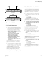
2.3 Power Line Connection............................................................................................................... 8
2.4 Line-Voltage Regulation.............................................................................................................. 8
2.5 Test-Fixture Connections............................................................................................................. 9
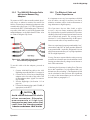
2.6 Bias Voltage for the DUT............................................................................................................ 9
2.6.1 Internal Bias...................................................................................................................... 9
2.6.2 External Bias..................................................................................................................... 9
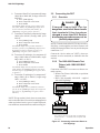
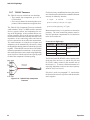
2.7 IEEE-488 Interface...................................................................................................................... 10
2.7.1 Description........................................................................................................................ 10
2.7.2 Signal Identification.......................................................................................................... 10
2.7.3 Codes and addresses.......................................................................................................... 10
2.8 Environment................................................................................................................................ 12
2.9 Rack Mount Option..................................................................................................................... 12
Table of Contents
iii
1693 RLC Digibridge
Chapter 3 Operation
3.1 Basic Operation........................................................................................................................... 13
3.1.1 Overview........................................................................................................................... 13
3.1.2 Startup............................................................................................................................... 13
3.1.3 Zeroing.............................................................................................................................. 14
3.1.4 Routine Measurement....................................................................................................... 17
3.2 Connecting the DUT.................................................................................................................... 18
3.2.1 Overview........................................................................................................................... 18
3.2.2 The 1689-9600 Remote Test Fixture (with 1689-9602 BNC Cable)................................ 18
3.2.3 Using the Test-Fixture Adaptors for Axial-Lead DUT...................................................... 19
3.2.4 1657-9600 Banana Plug Extender Cable.......................................................................... 20
3.2.5 The 1689-9602 Extender Cable with bnc-to-Banana-Plug Adaptors................................ 21
3.2.6 The Effects of Cable and Fixture Capacitances................................................................ 21
3.2.7 7000-05 Tweezers.............................................................................................................. 22
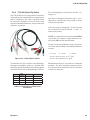
3.2.8 1700-03 Kelvin Clip Cable............................................................................................... 23
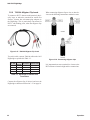
3.2.9 7000-04 Alligator Clip Leads............................................................................................ 24
3.2.10 Connection to HACS-Z High Accuracy Decade Capacitor............................................ 25
3.2.11 Connection to 1482 Inductance Standard........................................................................ 27
3.2.12 Connection to 1409 Capacitance Standards.................................................................... 28
3.2.13 Connection to 1404 Reference Standard Capacitor........................................................ 29
3.2.14 Connection to 1417 Capacitance Standard...................................................................... 30
3.2.15 Connection to the 1433 Decade Resistor........................................................................ 31
3.3 Measurement Parameters, Result Displays, and Outputs............................................................ 33
3.3.1 Parameters (R/Q,L/Q,
C/D,C/R,R/X,G/B,Z/ANG,Y/ANG)............................................................................................. 33
3.3.2 Equivalent Circuits - Series, Parallel................................................................................. 34
3.3.3 Results Displayed.............................................................................................................. 37
3.3.4 Units, Multipliers, and Blank Displays............................................................................. 39
3.3.5 D, Q, ANG in PPM............................................................................................................ 40
3.3.6 Ratio Displays, Virtual Range Extensions, and Conductance Measurements.................. 41
3.4 Principal Test Conditions............................................................................................................. 42
3.4.1 Test Frequency.................................................................................................................. 42
3.4.2 Test Voltage....................................................................................................................... 43
3.4.3 Constant Voltage Source................................................................................................... 44
3.4.4 Constant Current Source................................................................................................... 44
3.4.5 Other Conditions............................................................................................................... 44
iv
Table of Contents
1693 RLC Digibridge
3.5 Measurement Time and Measurement Ranges............................................................................ 45
3.5.1 General.............................................................................................................................. 45
3.5.2 Measure Rate Selection at Keyboard................................................................................ 45
3.5.3 Settling Time or Programmed Delay, in Triggered Measure Mode.................................. 46
3.5.4 Measure Mode and Display Selection, Effects on Measurement Time............................ 46
3.5.5 Integration-Time Factor (a Special Function)................................................................... 46
3.5.6 Ranges and Range Changing............................................................................................. 47
3.5.7 Range Holding................................................................................................................... 48
3.5.8 Time Required for Obtaining Median Values and Averaging........................................... 49
3.5.9 Time Required if IEEE-488 Output is Enabled................................................................. 50
3.5.10 Effect of Selecting a Low Test Frequency on Measurement Time................................. 50
3.5.11 Measurement Time Summary......................................................................................... 51
3.6 Accuracy, The Limits of Errors................................................................................................... 52
3.6.1 General.............................................................................................................................. 52
3.6.2 Accuracy for Some Typical Conditions............................................................................. 53
3.6.3 Averaging to Improve Accuracy........................................................................................ 54
3.6.4 Selection of Median Value for Better Accuracy................................................................ 55
3.6.5 Accuracy Enhancement for Large or Small Impedances at Particular Frequencies.......... 55
3.6.6 Accuracy Enhancement by Special Attention to Short-Circuit Inductance....................... 56
3.6.7 Cable-Related Errors and How to Correct for them.......................................................... 57
3.6.8 Use of Signal Reversing (Special Function) for Tests at Power Frequencies................... 58
3.6.9 Accuracy When Holding a Non-Optimum Range............................................................. 59
3.7 Bias for the DUT......................................................................................................................... 59
3.7.1 Internal Bias...................................................................................................................... 59
3.7.2 External Bias..................................................................................................................... 60
3.7.3 Suppression or Transients.................................................................................................. 62
3.8 Bin Sorting and Go/No-Go Results............................................................................................. 62
3.8.1 Introduction to Binning (Sorting Based on Limit Comparisons)...................................... 62
3.8.2 Sorting Methods................................................................................................................ 62
3.8.3 Limit Entry Procedure....................................................................................................... 63
3.8.4 Verification of Nominal and Limit Values......................................................................... 64
3.8.5 Examples of Limit Entry................................................................................................... 65
3.8.6 Notes on Limit Entries in General..................................................................................... 66
3.8.7 Go/No-Go and Bin Assignment Results............................................................................ 67
3.8.8 Bin Sum Information......................................................................................................... 67
3.8.9 Binning and Ratio Measurement Simultaneously............................................................. 67
v
1693 RLC Digibridge
3.9 Keyboard Lock, Function Map, and Summary of Integrations................................................... 69
3.9.1 Keyboard Lock.................................................................................................................. 69
3.9.2 Function Map.................................................................................................................... 69
3.9.3 Summary of Interrogations................................................................................................ 70
3.10 Special Functions....................................................................................................................... 71
3.11 Data Output and Programming via IEEE 488 and RS-232 Interface........................................ 72
3.11.1 Overview......................................................................................................................... 72
3.11.2 Configuration................................................................................................................... 72
3.11.3 Talk-Listen / Talk-Only Toggle Switch........................................................................... 72
3.11.4 GPIB Address DIP Switch............................................................................................... 73
3.11.5 Jumpers............................................................................................................................ 73
3.11.6 RS-232 Serial Interface (Currently Not Implemented)................................................... 73
3.11.7 Instrument Program Commands...................................................................................... 74
3.11.8 Legacy Digibridge IEEE-488 Commands....................................................................... 75
3.11.9 IEEE 488.2/SCPI Digibridge Command Summary........................................................ 77
3.11.10 IEEE 488.2 / SCPI Digibridge Command Reference.................................................... 80
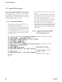
3.11.11 Example Programming.................................................................................................. 91
3.11.12 Talk-Only Use, for Data Output.................................................................................... 91
3.11.13 Talk/Listen Use, for Remote Programming and Data Transfers................................... 94
3.11.14 Data Output in Compacted Binary Format.................................................................... 97
3.12 Sample IEEE Programs............................................................................................................. 100
3.12.1 Programming Hints......................................................................................................... 100
3.12.2 National Instruments GPIB-PCll Card With the PC....................................................... 100
3.13 Self-checks and Failure Displays (Error codes)........................................................................ 101
3.13.1 Power-up Self-Check...................................................................................................... 101
3.13.2 Failure Display due to Signal Overload.......................................................................... 102
3.13.3 Failure Display due to Abnormal Measurement Cycle................................................... 102
3.13.4 Failure Display due to LC Resonance............................................................................. 102
Chapter 4 Theory
4.1 Introduction................................................................................................................................. 104
4.1.1 General.............................................................................................................................. 104
4.1.2 Brief Description of the 1693 Digibridge......................................................................... 104
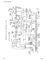
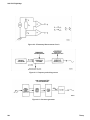
4.1.3 Block Diagram.................................................................................................................. 105
4.2 Principal Functions...................................................................................................................... 107
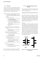
4.2.1 Elementary Measurement Circuit...................................................................................... 107
4.2.2 Frequency and Time Source.............................................................................................. 107
vi
Table of Contents
1693 RLC Digibridge
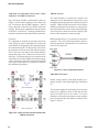
4.2.3 Sine-Wave Generation....................................................................................................... 107
4.2.4 The Dual-Slope Integrating Detector and Converter........................................................ 109
Chapter 5 Service and Maintenance
5.1 Safety........................................................................................................................................... 110
5.2 Customer Service......................................................................................................................... 111
5.3 Instrument Return........................................................................................................................ 111
5.3.1 Packaging.......................................................................................................................... 111
5.3.2 Repair and Replacement of Circuit Boards....................................................................... 111
5.4 Performance Verification............................................................................................................. 112
5.4.1 Overview........................................................................................................................... 112
5.4.2 Performance Verification Procedure.................................................................................. 112
5.4.3 Measurement-Time Checkout........................................................................................... 115
5.5 Disassembly and Access.............................................................................................................. 116
5.5.1 Relocation of bnc Connector Bracket............................................................................... 119
5.5.2 Major internal components................................................................................................ 120
5.5.3 Interface Options............................................................................................................... 121
5.5.4 Removal of Multiple-Pin Packages................................................................................... 122
5.6 Periodic Maintenance.................................................................................................................. 122
5.6.1 Care of Test Fixtures......................................................................................................... 122
5.6.2 Care of the Display Panel.................................................................................................. 122
5.7 Trouble Analysis.......................................................................................................................... 123
5.7.1 Overview........................................................................................................................... 123
5.7.2 Power-Up Self check and Certain Aborted Measurements............................................... 124
5.7.3 Internal Fuse Replacement................................................................................................ 127
5.7.4 Power Supply and Regulator Board.................................................................................. 128
5.7.5 Sinewave Generator Checks.............................................................................................. 129
5.7.6 Front End Amplifiers and Switches................................................................................... 129
5.8 Accuracy Verification.................................................................................................................. 130
5.8.1 General.............................................................................................................................. 130
5.8.2 Capacitance Measurement Accuracy (Ranges 1-3)........................................................... 131
5.8.3 Capacitance Measurement Accuracy................................................................................ 132
5.8.4 Resistance Measurement Accuracy................................................................................... 134
5.8.5 Inductance Measurement Accuracy.................................................................................. 135
5.8.6 D Measurement Accuracy................................................................................................. 137
5.8.7 Limit Comparison Bins..................................................................................................... 138
Table of Contents
vii
1693 RLC Digibridge
5.9 Recalibration................................................................................................................................ 140
5.9.1 Preparation........................................................................................................................ 140
5.9.2 Zeroing and Selecting “DQ in PPM”................................................................................ 141
5.9.3 Recalibration for Range 4................................................................................................. 141
5.9.4 Recalibration for Range 3................................................................................................. 142
5.9.5 Recalibration for Range 2................................................................................................. 142
5.9.6 Recalibration for Range 1................................................................................................. 143
5.9.7 Frequency Calibration....................................................................................................... 143
5.9.8 Frequency Correction K Factor Procedure........................................................................ 144
5.10 Internal Address Settings for IEEE-488 Interface..................................................................... 146
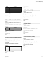
Figures and Tables
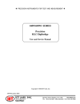
Figure-A: Source Impedance Factors..........................................................................................................xv
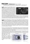
Figure 1-1: 1693 RLC Digibridge, front view............................................................................................2
Figure 1-2: 1693 Front Display.................................................................................................................3
Figure 1-3: 1693 Keyboard........................................................................................................................3
Figure 1-4: Rear controls and connectors on 1693 Digibridge.................................................................5
Figure 1-5: Typical operating guide attached to 1693...............................................................................7
Figure 2-1: Input power module with a drawer for the input fuse.............................................................8
Figure 2-2: IEEE-488 interface..................................................................................................................10
Figure 2-3: DIP switch set to Decimal Address 3......................................................................................11
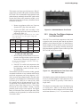
Figure 3-1: Open and short measurements with banana plugs..................................................................14
Figure 3-2: Open and short measurements with Kelvin cables..................................................................15
Figure 3-3: Open and short measurements with bnc-to-bnc cables...........................................................15
Figure 3-4: Open and short measurements with GR874 connectors.........................................................16
Figure 3-5: Chip component tweezers........................................................................................................16
Figure 3-6: Open and short measurements in 1689-9600..........................................................................17
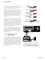
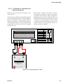
Figure 3-7: Connecting remote test fixture to RLC Digibrige....................................................................18
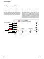
Figure 3-8: 1689-9600 Remote Test Fixture...............................................................................................19
Figure 3-9: 1689-9600 Remote Test Fixture with 1657-5995 Test Clips....................................................19
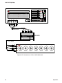
Figure 3-10: Banana plugs on the 1657-9600 cable..................................................................................20
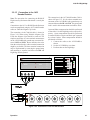
Figure 3-11: Connecting remote test fixture and the Extender cable to RLC Digibrige............................20
Figure 3-12: 1689-9602 Extender Cable with bnc-to-banana-plug adapters............................................21
Figure 3-13: 7000-05 Chip Component Tweezers......................................................................................22
Figure 3-14: 1700-03 Kelvin Cables..........................................................................................................23
Figure 3-15: 7000-04 Alligator Clip Leads................................................................................................24
Figure 3-16: Connecting alligator clips ....................................................................................................24
Figure 3-17: Connection to HACS-Z BP terminals with 1689-9602 cable and 1894 & 4684 adapters....25
Figure 3-18: Connection to HACS-Z BP terminals with 1657-9600 Extender Cable
or 7000-04 cable (without alligator clips)...........................................................................................25
Figure 3-19: Connection to HACS-Z bnc terminals with 1689-9602 cable with 6700 adapters...............26
Figure 3-20: Connecting 1693 to 6-terminal 1482....................................................................................27
Figure 3-21: Direct connection of 1693 and 1482.....................................................................................27
Figure 3-22: Connecting 1693 to a 3-terminal 1482.................................................................................28
Figure 3-23: Connection to 1409 Standard Capacitor...............................................................................28
Figure 3-24: Connecting 1693 to a 1404...................................................................................................29
Figure 3-25: Connecting to a 1417............................................................................................................30
viii
Table of Contents
1693 RLC Digibridge
Figure 3-26: Connection to 1433 via 7000-04 cable.................................................................................31
Figure 3-27: Connection to 1433 via 1657-9600 cable.............................................................................32
Figure 3-28: Phase relationships...............................................................................................................37
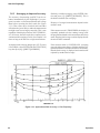
Figure 3-29: Relationships of Measurement Time......................................................................................51
Figure 3-30: General view of the tradeoffs between measurement time and accuracy.............................53
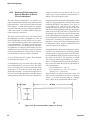
Figure 3-31: Approximate RLC Accuracy vs Test Frequency.....................................................................54
Figure 3-32: Recommended Wire Shapes for Zeroing................................................................................56
Figure 3-33: Nested limits for sorting........................................................................................................63
Figure 3-34: Sequential limits for sorting..................................................................................................63
Figure 3-35: Keyboard Map.......................................................................................................................69
Figure 4-1: Block diagram of the 1693 RLC Digibridge...........................................................................106
Figure 4-2: Elementary Measurement Circuit............................................................................................108
Figure 4-3: Frequency and timing source..................................................................................................108
Figure 4-4: Sine wave generator................................................................................................................108
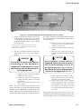
Figure 5-1: Screws holding the interface assembly on the rear panel.......................................................117
Figure 5-2: Interior top view of 1693 Digibridge......................................................................................118
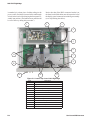
Figure 5-3: Analog and Control Board Assembly (1689-4702).................................................................120
Figure 5-4: Display Board Assembly (1689-4705).....................................................................................120
Figure 5-5: Keyboard Assembly (1687-4200)............................................................................................121
Figure 5-6: Power Supply Assembly (700011)...........................................................................................121
Figure 5-7: IEEE interface (1689-9640), front view..................................................................................121
Figure 5-8: IEEE interface (1689-9640), top view.....................................................................................121
Figure 5-9: Screws holding the interface assembly on the rear panel.......................................................122
Figure 5-10: Timing diagram of the power-up self check..........................................................................124
Figure 5-11: Location of internal fuse........................................................................................................127
Figure 5-12: Power Supply and Regulator Board Test Points...................................................................128
Figure 5-13: Series connections of standards for D accuracy checks.......................................................137
Figure 5-14: Calculating the K factor........................................................................................................145
Figure 5-15: IEEE-488 interface on the rear panel...................................................................................146
Table of Contents
ix
1693 RLC Digibridge
This page is intentionally left blank.
x
Table of Contents
1693 RLC Digibridge
SAFETY
INFORMATION
General safety information
Safety Summary
The following general safety precautions must be
observed during all phases of operation, service
and repair of this instrument. Failure to comply
with these precautions or specific WARNINGS
given elsewhere in this manual will violate safety
standards of the design, manufacturing, and
intended use of the instrument. IET Labs. assumes
no liability for the customer’s failure to comply with
these requirements.
Before Applying Power
Verify that the power is set to match the rated input
of this instrument.
Protective Ground
Make sure to connect the protective ground to
prevent an electric shock before turning on the
power.
Necessity of Protective Grounding
Never cut off the internal or external protective
ground wire, or disconnect the wiring of the
protective grounding terminal. Cutting the
protective ground could cause a potential shock
hazard and result in injury to a person.
Do not operate in an explosive atmosphere
Do not operate this instrument in the presence of
flammable gases or fumes.
Do not remove the cover of the instrument
Operating personnel must not remove the cover
of this instrument. Component replacements and
internal adjustments can be done only by qualified
service personnel. Dangerous voltages may be
present inside this instrument. Do not open the case
Refer servicing to qualified personnel.
Disposal
Do not dispose of electrical appliances as unsorted
municipal waste, use separate collection facilities.
Contact your local government for information
regarding the collection systems available. If
electrical appliances are disposed of in landfills
or dumps, hazardous substances can leak into the
groundwater and get into the food chain, damaging
your health and well-being. When replacing old
appliances with new one, the retailer is legally
obligated to take back your old appliances for
disposal.
Fuses
Only fuses with the required rated current, voltage
and specified type (normal blow, time delay, etc.)
should be used. Do not use repaired fuses or shortcircuited fuse holders. Using the wrong fuse could
cause a shock or fire hazard.
Safety Information
xi
1693 RLC Digibridge
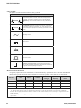
Safety Symbols
The product is marked with the following safety symbols.
Safety Symbols
The WARNING sign denotes a hazard to the user. It calls attention
to a procedure, practice, or the like, which, if not correctly performed
or followed, could result in personal injury. Do not proceed beyond a
WARNING sign until the indicated conditions are fully understood and
met.
WARNING
The CAUTION sign denotes a hazard to the equipment. It calls attention
to procedures, practices and conditions, which, if not observed, could
result in damage to the equipment or invalidating a procedure and/or test
results.
CAUTION
Alternating Current
Direct Current
I
On (Power Supply)
0
Off (Power Supply)
Protective grounding terminal: Protects against electrical shock in
case of a fault. This symbol indicates the terminal must be connected to
the ground wire before operating the equipment.
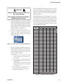
Material Contents Declaration
A regulatory requirement of The United States of America defined by specification SJ/T 11364-2006 mandates that
manufacturers provide a material contents declaration of electronic products. IET’s materials are listed below.
Part Name
Lead
Mercury
Hazardous Substances
Hexavalent
Cadmium
Chromium
Cd
Cr6+
Polybrominated Polybromodiphenyl
Biphenyls
Ethers
PBB
PBDE
Pb
Hg
PCBA
X
O
O
O
O
O
CHASSIS
X
O
O
O
O
O
ACCESSORY
X
O
O
O
O
O
PACKAGE
O
O
O
O
O
O
“O” indicates that the level of the specified chemical substance is less than the threshold level specified in the standards.
“X” indicates that the level of the specified chemical substance exceeds the threshold level specified in the standards.
IET Labs. has not fully transitioned to lead-free solder assembly at this moment; however, most of the components used are
RoHS compliant.
The environment-friendly usage period of the product is assumed under the operating environment specified in each product’s
specification.
xii
Safety Information
1693 RLC Digibridge
ABBREVIATED
SPECIFICATIONS
Features
• The world’s de facto standard for ac resistance,
low-frequency inductance, and capacitance
measurement
• 0.02% accuracy for R,L,C, G, Z, and Y
• 0.0001 accuracy for Dissipation and Q
• 11 Impedance Parameters
• Programmable test frequencies from 12 Hz to
200 kHz for testing versatility
• Programmable test voltages from 5 mV to
1.275 V
• Dual display featuring 5-digit readout for RLC
and 4-digit readout for D and Q
• Extremely reliable: over 30 years of history
• Optional IEEE-488 interface allows test protocols and results to be stored in PC’s
Applications
• High-end metrology applications
• Measuring impedance (inductance, capacitance, and resistance)
• Testing and sorting electrical components based
on 11 possible parameters
• Optional IEEE-488 interface allows test protocols and results to be stored in PC’s
Specifications
Measurement parameters:
Eight combinations of parameters are measured:
R and Q, C and D, L and Q, C and R, R and X, G
and B, Z(magnitude) and angle and Y (magnitude)
and angle as selected by the R/Q, C/D, L/Q, or C/R
keys, or the SHIFT key and the R/X, G/B, Z/ang/
or Y/ang keys. Either series or parallel equivalent
circuit values are measured for R, C, and L as
selected by the EQUIVALENT CIRCUIT key.
Series values are measured for R and X combination
and parallel values are measured for G and B.
Parameter selection is initially made automatically
based on the DDT being measuring. Automatic
selection is inhibited once a specific parameter
key has been selected by the operator (but may be
restored).
Display format:
Dual display featuring 5 full digit LED for
RLCGZY and full digit LED for DQRXBΘ
Automatically positioned decimal points and minus
signs where appropriate
Individual LED indicators for parameters, and
measurement units
MEASURE displays:
When the MEASURE function has been selected,
either VALUE, ∆RLC, ∆% or BIN NO. may be
displayed.
VALUE display:
The VALUE display provides five digits for
measured primary parameter (first quantity in each
pair given above) four digits for secondary quantity
Abbreviated Specifications
xiii
1693 RLC Digibridge
(second parameter in each pair) with automatically
positioned decimal points, units of measurement
and minus signs when appropriate.
The ∆RLC display:
The ∆RLC display indicates the difference between
the measured R, L or C and a nominal value entered
by the user with appropriate units (Ω, µF etc.). The
R, L,or C difference display has five digits with a
simultaneous four digit direct reading display of
D, Q, or R with automatically positioned decimal
points and minus signs when appropriate.
The ∆% display:
The ∆% display indicates the % deviation of the
measured primary quantity and the stored nominal
value. The display is five digits with a maximum
resolution of one part per million with minus sign
when appropriate. The resolution of the DQ and
angle displays may also be increased by using the
DQ in PPM key which gives D or Q in ppm or angle
in microdegrees.
The BIN NO. display:
The BIN NO. display provides a single digit bin
assignment number based on the measured value
and user entered bin limits.
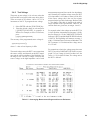
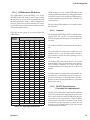
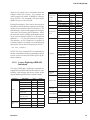
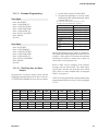
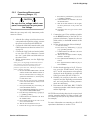
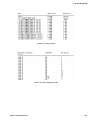
Measurement modes and rates:
There are two test modes, CONTINUOUS and
TRIGGERED. The CONTINUOUS mode makes
successive measurements continually, updating
the display after each measurement. TRIGGERED
measurements are initiated by the START button or
remotely from the IEEE bus and the result held until
another measurement is started.
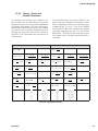
There are three measurement rates selected by
single keys; SLOW, MEDIUM and FAST whose
measurement times depend on the test frequency
(see table below for C and D, L and Q, or R and Q
speeds). Other measurement rates may be selected
by programming the integration time, AVERAGING
to 255 measurements or adding a programmed
DELAY of 1 to 99999 ms.
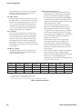
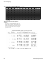
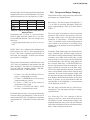
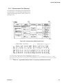
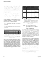
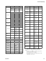
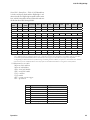
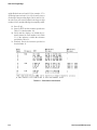
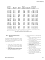
The measurement times in the following table
were obtained with the use of the high-speed
measurement option, continuous measurement
mode, bin number display, and without IEEE-Bus
data output. For other conditions refer to the notes
below the table.
If the measurement mode is triggered, programmed
delay (settling time), if any, should be added.
Normal power up conditions include a programmed
delay of 7/f to 12/f ms depending upon
measurement rate. This delay can be programmed to
zero or any value up to 100 s.
Measurement
Rate
12 Hz
100 Hz
120 Hz
1 kHz
10 kHz
100 kHz
200 kHz
SLOW
899 ms
944 ms
944 ms
974 ms
944 ms
944 ms
944 ms
MEDIUM
694 ms
144 ms
194 ms
204 ms
194 ms
194 ms
194 ms
FAST
694 ms
129 ms
114 ms
89 ms
79 ms
79 ms
79 ms
MAXIMUM
672 ms
113 ms*
98 ms*
44 ms
34 ms
34 ms
34 ms
*These times can be shortened by 14ms by using the special quick acquisition routine.
Notes:
1. If the display is value, ∆%or ∆RLC, add 3 to 5 ms.
2. If data is output via the IEEE Bus, add 3 to 6 ms.
3. Speed in the table far e for C with D, L with Q or R with Q measurements.
Table-A: Measurement Rate
xiv
Abbreviated Specifications
1693 RLC Digibridge
Test frequencies:
Over five hundred test frequencies between 12 Hz
and 200 kHz may be selected by keyboard entry.
These are:
f = 200 kHz/n, where n = 1 to 13
f = 60 kHz/n, where n = 4 to 256
f= 3 kHz/n, where n = 13 to 250
For example frequencies that can be selected:
200 kHz/1 = 200 kHz
200 kHz/2 = 100 kHz
....
200 kHz/13 = 15.384.6 kHz
If the exact frequency selected is not available, the
nearest available frequency is used. The accuracy of
the test frequency is better than .01%.
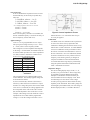
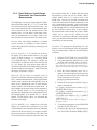
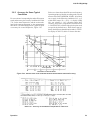
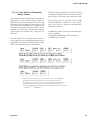
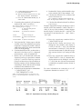
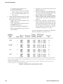
Applied Voltages:
5 mV to 1.275 V (programmable in 5 mV steps).
The open circuit voltage accuracy is (5% + 2mV)
(1 + .001f2) where f is the frequency in kHz.
This voltage has a source impedance that depends
on the range. A CONSTANT VOLTAGE mode can
be selected which provides a low source impedance
(25 ohms) in order to maintain a constant ac test
level over a wider impedance range.
Range
Source Resistance/
Impedance
1
97.4 kΩ
2
6.4 kΩ
3
400 Ω
4
25 Ω
Constant Voltage
25 Ω
Table-B: Range versus internal source
resistance
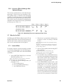
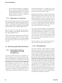
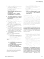
The programmed level is obtained under an open
circuit condition. The actually applied voltage can
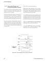
be determined as follows.
A source resistance (Rs, internal to the meter) is
effectively connected in series with the AC output
and there is a voltage drop across this resistor. When
a test device is connected, the voltage applied to the
device depends on the value of the source resistor
(Rs) and the impedance value of the device. As an
example, where Range 4 is used which has a source
impedance Rs of 25 ohms and the programmed
voltage is 1 V but the voltage to the DUT is 0.5 V.
Abbreviated Specifications
Figure-A: Source Impedance Factors
Internal dc bias is 2 V. External dc bias of up to
60 V may be applied.
Calibrations
An OPEN circuit zero calibration can be performed
to remove the effects of stray capacitance and
conductance shunting the internal test fixture or any
other fixture or cable connection . A similar SHORT
circuit zero calibration can be performed to remove
the effects of resistance and inductance in series in
the test connections . New zero calibrations should
be made to obtain best accuracy whenever the test
frequency or the fixture geometry is changed. A
complete recalibration of the internal standards
for each measurement range may be performed by
using the optional 1689-9604 Calibration Kit and
either a 1689-9600 Test Fixture.
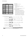
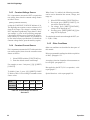
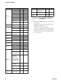
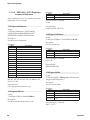
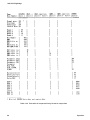
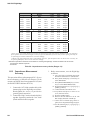
Impedance Ranges:
The direct reading display ranges for R, L. C, G,
|Z| and |Y| are given in Table A. These ranges may
be extended by using the RATIO mode which
multiplies or divides the measured result by an
entered number but does not display a unit. These
extended ranges are also shown. These ranges
exceed by far any practical values and the accuracy
capability of the instrument. The D and Q ranges are
not changed by the RATIO mode, nor is the range of
R when displayed with C, X with R or B with G.
xv
1693 RLC Digibridge
Parameter
Direct Reading
Range
R and [Z]
0.00001 Ω to
99999 kΩ
R with C
9999 kΩ
Range selection:
Autoranging with manual hold
Ratio and DQ in PPM
0.00010 Ω to 9999.9 GΩ
Basic accuracy*:
Basic RLCGZY: ±0.02%
0.00001 mH to
0.00010 nH to 9999.9 MH
L
99999 H
Basic QD: ±0.0002 (±0.0001 in PPM mode)
0.00001 pF to
0.00010 aF to 9999.9 F
Basic RXB: ±0.02%
C
99999 µF
Θ: ±0.01°and |Y|
Table A Direct Reading Display Ranges for R,L,C,G,|Z|,
0.00001 µS to
0.00010 pS to 9999.9 MS
G and [Y]Insert99999
from
Datasheet: Ranges Table *See accuracy formulas below for actual accuracy based
S
upon instrument configuration and DUT.
0.0001 Ω to
not extended
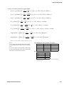
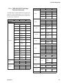
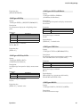
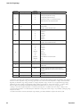
Limit of error (accuracy):
Ω to
not extended
Limit 0.0001
of Error
(accuracy):
The specified limit of error is given below for
9999 kΩ
conditions
(except constant
voltage,
for this voltage, for
The specified
limitnotof
error is given belowallfor
all conditions
(except
constant
0.0001 µS to
extended
B with G
9999 S
condition
add
2
inside
the
brackets).
Rx,
Cx, Lx etc.
this condition add 2 inside the brackets). Rx, Cx, Lx etc. are the measured
values, f is
0.0001 to 9999
1 to 9999 ppm
are the measured values, f is the frequency in kHz.
D with C
the frequency in kHz. The range constants Rmax, Lmax, Cmin, Gmin etc are given in
The range constants Rmax, Lmax, Cmin, Gmin etc
0.0001 to 9999
1 to 9999 ppm
Q with R or L
Table B. The constants Ks and Kfv are given
in Tables 0 and D. Note that for SLOW
are given in Table-D. The constants Ks and Kfv
±0.0001° to 180°
±1 to 999 microdegrees
Angle
measurements at 1kHz and 1 V with non are
constant
voltage
K constants
given in Tables
0 and these
D. Note that
for SLOW are all
Table-C:
Impedance
ranges
zero and that f =1.
measurements at 1kHz and 1 V with non constant
X with R
voltage these K constants are all zero and that f =1.
Primary parameters (lefthand readout):
Accuracy of primary parameters (left readout):
)
)
)
)
)
)
To obtain accuracy, IET offers a convenient tool at: http://www.ietlabs.com/notes/digibridge_accuracy_
To obtain
offers ashown
convenient
tool
calculator.
This tool accuracy,
is equivalent to IET
the calculations
for both primary
andat:
secondary parameters.
Note:http://www.ietlabs.com/notes/digibridge_accuracy_calculator
This calculation tool is applicable for both 1689 and 1693 Digibridge modles.
.
This tool is equivalent to the calculations shown for both primary and secondary
parameters.
xvi
Abbreviated Specifications
1693 RLC Digibridge
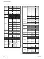
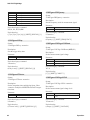
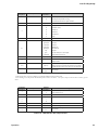
Secondary parameters (righthand readout)
Accuracy of secondary parameters (right readout):
)
)
)
)
)
~ Remove this term of 0.0001, if DQ in PPM mode is used.
~ Remove
this term of 0.0001, if DQ in PPM mode
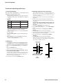
is used. range constants vs frequency:
High-Impedance
Notes
:
1. It is assumed that both that OPEN and SHORT
Constants
12 Hz to 20 kHz >20 kHz to 200 kHz
Notes :
zeroing calibrations are made at the test frequency
Rmax, Zmax, Xmax:
1 MΩ
60 kΩ
1. It is assumed that both that OPEN and SHORT zeroing calibrations
used.
Lmax
160 H
10 H
are made at the test frequency used.
2. Accuracy applies for measurements made using
Cmin
160 pF
3 nF
2. Accuracy applies for measurements made using the 1689-9602 Extender
the 1689-9602 Extender Cable with or without the
Gmin, Ymin, Bmin
1 µS
15 µS
CabLewith or without the 1689-9600 or 1689-9605 Test Fixture.
1689-9600 or 1689-9605 Test Fixture.
Ks as a function of measurement rate:
Table B High-Impedance Range Constants vs Frequency
Measurement Rate
Slow
Constants
Rmax, Zmax, Xmax:
Lmax
Cmin
Gmin, Ymin, Bmin
12Hz to 20kHz
1 Mohm
160 H
160 pF
1 uS
Ks
0
>20kHz to 200kHz
3
60 kohm
Fast
8
10 H
Maximum*
23
3 nF
* = Maximum is FAST measurement mode with minimum
15 uS
integration time.
Medium
Table C Ks as a Function of Measurement Rate
Measurement
Slow
Medium
Fast
Rate
Ks
0
3
8
* = Maximum is FAST measurement mode with minimum integration time.
Abbreviated Specifications
Maximum*
23
xvii
1693 RLC Digibridge
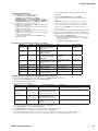
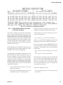
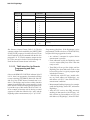
Kfv as a Function of Frequency and RMS Voltage:
12 Hz to
<30 Hz
Frequency
30 Hz to 100 Hz to 250 Hz to
>1 kHz to >3 kHz to >6 kHz to >10 kHz to >20 kHz to >20 kHz
1 kHz
200 kHz
<1 kHz
<100 Hz <250 Hz
3 kHz
6 kHz*
10 kHz*
20 kHz*
50 kHz* to 50 kHz*
1 V to 1.275 V AC Applied Voltage
5
3
2
1
0
1
1*
3*
5*
8
18
70
2
1
2
2*
4*
6*
12
25
80
5
4
5
6*
8*
10*
20
50
100
20
14
15
15*
20*
25*
40
100
**
60
50
50
50*
50*
60*
70
**
**
0.25 V to < 1 V AC Applied Voltage
8
5
3
0.1 V to < 0.25 V AC Applied Voltage
12
8
6
0.03 V to < 0.1 V AC Applied Voltage
35
30
25
0.01 V to < 0.03 V AC Applied Voltage
90
80
70
* Multiply Kfv values by 5 from 3kHz to 20kHz for Range 1 (Z > 25 kohms)
** Not Specified
Measurement ranges and source impedance/
resistance:
The 1693 has 4 measurement ranges, Range 1 to
Range 4, that have specific source resistance. The
Ranges can be automatically or manually selected.
The source resistance does reduce the AC signal
applied to the DUT.
xviii
Abbreviated Specifications
1693 RLC Digibridge
Special functions:
Several special features may be selected including:
Binning:
Pass bins: 13 pass bins for RLCGZY
Fail bins: 2 fail bins, RLCGZYΘ
Sorting capabilities:
Bin number, Delta RLC, Delta %, Value
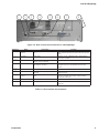
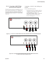
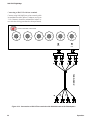
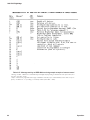
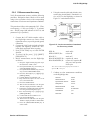
DUT connections:
The 1693 has four BNC connections to make
four-terminal (Kelvin) connections to the device
under test. These connections are shielded and the
instrument ground has a guard for three-terminal
measurements. 1689-9602 1-meter BNC Cable
Set is provided. Various test fixtures and other
accessories are available.
Front of
1689-9602
Description
1693
BNC Cable
IL
1689-9600 Remote
Test Fixture*
Drive -
IL/Black Band
I+
PL
Potential -
PL/Black and
White Band
P+
PH
Potential +
PH/Red and
White Band
P-
IH
Drive +
IH/Red Band
I-
*High and Low Reversed for correct operation
Charged capacitor protection:
The instrument is protected from damage due to the
connection of charged capacitors with up to 1 joule
of stored energy: Stored Energy = ½CV2 Joules
Keyboard lock:
The keyboard can be locked to prevent inadvertent
changes to test conditions and sorting routines.
Parameter storage:
All keyboard settings and programmed nominal
values and bin limits can be stored in non-volatile
memory for automatic reentry upon power up .
Self-Check diagnostics:
Self-tests are performed during power-up to verify
proper operation and validity of calibration. Coded
error signals on the display notify the operator if a
problem is encountered.
Abbreviated Specifications
• Direct Range Setting
• Range Extension (RATIO mode)
• Integration Time
• Blanking of lesser digits
• Signal reversal for hum removal under adverse
conditions
• A Median value routine
• Automatic parameter selection
• Quick acquisition routine
• Choice of data output on IEEE bus
• Interface Option: IEEE-488 Bus (1689-9640)
Zeroing:
Open and short circuit compensation
Power:
90-250 Vac
50-60 Hz
60 W max
Environmental conditions:
Operating conditions: 0° to +50°C, <85% RH
Storage conditions: -45°C to +75°C
Dimensions:
43.8 cm W x 14.3 cm H x 38.5 cm D (17.3” x 5.6”
x 15.2”)
Weight:
6.4 kg (14 lbs)
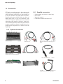
Supplied accessories:
Power cable
1689-9602 bnc-to-bnc extender cable, 1-meter
Instruction manual
Calibration certificate traceable to SI
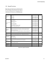
Optional accessories:
1700-03
Kelvin Test Leads
7000-04
Alligator Clip Leads, 1 Meter
7000-05
Chip Component Tweezers
1689-9602-2bnc-bnc Extender Cable, 2-Meter
1689-9600 Remote Test Fixture
1689-9640 IEEE Digibridge Interface
1689-9604 Digibridge Calibration Kit
1689-9611 Rackmount Kit
1657-9600 Banana-Plug Extender Cable
1658-2450 Bias cable
Calibration certificate accredited to ISO17025
xix
1693 RLC Digibridge
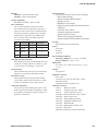
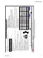
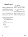
Condensed operating instructions
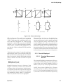
3. Obtaining optimal accuracy by zeroing
1. General Information
The 1693 RLC Digibridge is a microprocessorcontrolled, automatic RLC meter.
Measurement parameters: R/Q, L/Q, C/D (series
or parallel), R/X (series), G/B (parallel), Z/Angle or
Y/Angle
Ranges:
Parameter
R and [Z]
L
C
Direct Reading Range
Ratio and DQ in PPM
0.00001 Ω to 99999 kΩ
0.00010 Ω to 9999.9
GΩ
0.00001 mH to 99999 H
0.00010 nH to 9999.9
MH
0.00001 pF to 99999 µF
0.00010 aF to 9999.9 F
Test frequencies: Over 500 selectable test
frequencies ranging from 12 Hz to 200 kHz
Applied voltage: 5 mV to 1.275 V (programmable
in 5 mV steps)
Measurement speed: Up to 19 measurements per
second
Bias: Internal: 2.0 Vdc; External: 60 Vdc max
Accuracy: Basic RLCGZY: ±0.02%
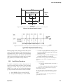
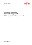
Before making measurements, zero the Digibridge as follows: (Note: For best accuracy, repeat this procedure every
day, after each change of frequency, and after any change
of test-fixture adaptors.)
a.Attach extender cables or whichever test fixture/adapter is
appropriate.
b.Create an open circuit by having the spacing between +
and - cable ends match the spacing of the DUT terminals.
See the figure.
If the spacing of DUT terminals is unknown, make sure
that the + and – ends of the cable are at least 0.75” (19
mm) apart.
c.Confirm that MEASURE keyboard light is lit.
d.Press [MEASURE MODE] key to select TRIGGERED
mode
e.Press the following keys: [1] [6] [9] [3] [=] [SHIFT]
[OPEN].
f. Press [START] and wait for the green GO light.
g.Create a short circuit across test terminals by connecting all
cable ends together as shown in the figure.
h.Press the following keys: [1] [6] [9] [3] [=] [SHIFT]
[SHORT].
i. Press [START] and wait for the green GO light.
At this point, the unit should be ready for taking measurements. If something goes wrong during the zeroing process,
the procedure should be repeated.
2. Starting-up
a.If the Digibridge includes an optional IEEE-488 interface,
set [TALK] switch (rear panel) to TALK ONLY (unless
instructions are to be received through the IEEE-488 bus).
b.Make sure the [EXTERNAL BIAS] is in the OFF position.
c.Press the [POWER] button.
The unit runs a brief self-check on start-up.
d.Wait until keyboard lights indicate MEASURE, VALUE,
SLOW, TRIGGERED, SERIES.
If a fault is detected, measurements are blocked and an error code remains displayed. See manual, paragraph 3.13.
If keyboard lights remain dark, keyboard is locked. To
unlock it, see manual paragraph 3.9.
To switch power off, press the [POWER] button.
xx
Match spacing of
DUT terminals
Drive +
Drive +
Drive -
Sense +
Sense +
DUT
Drive -
Sense -
-
Sense +
Open
Connection
Short
Connection
Abbreviated Specifications
1693 RLC Digibridge
4. Taking measurements
a.Select measurement conditions as follows:
•
•
•
•
•
[FUNCTION] key selects MEASURE mode
[DISPLAY] key selects VALUE, ∆%, or BIN NO
[MEASURE RATE] key selects SLOW, MEDIUM, or FAST
[MEASURE MODE] key selects CONTINUOUS or TRIGGERED
[EQUIVALENT CIRCUIT] key selects SERIES or PARALLEL
b.Select impedance to be measured as follows
• [R/Q] key to show Resistance in the primary display and Quality
factor in the secondary display
• [L/Q] key to show Inductance in the primary display and Quality
factor in the secondary display
• [C/D] key to show Capacitance in the primary display and Dissipation in the secondary display
• [C/R] key to show Capacitance in the primary display and Resistance in the secondary display
• To select other parameters, press and hold [SHIFT] key and
select as appropriate
c.Connect component to be tested to the test terminals as
appropriate.
d.If in the TRIGGERED mode, press [START].
Keep hands and objects at least 10 cm (4 in) from test
fixture.
If NEG RLC lights, the selected parameter is not appropriate for the DUT and another parameter should be
selected. For example, if the Digirbdige is set to measure
capacitance, and NEG RLC is lit, that means that the
DUT is inductive.
To view relative measurements, the nominal value and the bin
limits must be first programmed. (See section 5 below.) Once
the values have been programmed, select one of the following
options by pressing the [DISPLAY] key:
The following programmable functions are available:
Parameter
Range
• % difference from the nominal value: ∆% must be lit
• Difference from nominal in original units (pF, mH, etc.): VALUE
and ∆% must both be lit
• Assigned bin number: BIN NO must be lit
Default Sample setting adjustment
Cancel
View Current Setting
Test frequency
12 Hz to 200
kHz
1 kHz
Programming 400 Hz:
[FUNCTION] [.] [4] [=] [SHIFT]
[FREQUENCY]
NA
[SHIFT] [FREQUENCY]
Test voltage
5 mV to
1.275 V
1V
Programming 15 mV:
[FUNCTION] [.] [0] [1] [5] [=]
[SHIFT] [VOLTAGE]
NA
[SHIFT] [VOLTAGE]
1 to 256
1
Programming 25 measurements:
[FUNCTION] [2] [5] [=] [SHIFT]
[AVERAGE]
[FUNCTION] [1] [=] [SHIFT]
[AVERAGE]
[SHIFT] [AVERAGE]
0 to 99,999 ms
0
Programming a delay of 200 ms:
[FUNCTION] [2] [0] [0] [=] [SHIFT]
[DELAY]
[FUNCTION] [0] [=] [SHIFT]
[DELAY]
[SHIFT] [DELAY]
NA
Averaging
Delay
Internal Bias
2V
OFF
[SHIFT] [INT BIAS]
[SHIFT] [INT BIAS] again
D and Q in PPM
NA
OFF
[SHIFT] [DQ in PPM]
[SHIFT] [DQ in PPM] again
NA
Hold constant
voltage
NA
OFF
[SHIFT] [CONST V]
[SHIFT] [CONST V] again
NA
Hold constant
range
NA
OFF
Select the desired range then
[SHIFT] [HOLD RNG]
[SHIFT] [HOLD RNG] again
NA
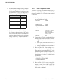
5. Setting limits for GO/NO GO testing and sorting into bins
a.Make sure the appropriate VALUE is selected by pressing [DISPLAY] key as necessary.
b.Make sure to select ENTER by pressing the [FUNCTION] key.
c.Select the desired range and multipliers.
d.Select bins and limits as follows:
Option
Sample setting
Sample setting adjustment
Closing the bin
QDRXBΘ limits (always
bin 0)
Limit of 85
[8] [5] [=] [SHIFT] [BIN NO] [0] [0]
Symmetrical percentage
tolerances for RLCGZY
(nested bins)
Nominal value of 123.4
[1] [2] [3] [.] [4] [=] [SHIFT] [NOM VAL],
[.] [2] [%] [=] [SHIFT] [BIN NO] [0] [1],
enter tolerances for more bins if necessary
[0] [=] [SHIFT] [BIN NO] [0] [1]
[1] [4] [.] [7] [5] [=] [SHIFT] [NOM VAL],
[.] [5] [=] [SHIFT] [BIN NO] [0] [2],
enter tolerances for more bins if necessary
[0] [=] [SHIFT] [BIN NO] [0] [2]
[2] [0] [%] [-] [8] [0] [%] [=] [SHIFT] [BIN
NO] [0] [6]
(upper limit should always come first)
[0] [=] [SHIFT] [BIN NO] [0] [6]
Multiple tolerances (bucket
sort)*
Asymmetrical tolerances
For D,R(series),X,B,Q/R: [9] [9] [9] [9] [=] [SHIFT] [BIN NO] [0] [0]
For R(parallel),Q/L: [0] [=] [SHIFT] [BIN NO] [0] [0]
with ±0.2% limits in bin 1
Nominal value of
14.75 Ω
with ±0.5 Ω limits in bin 2
+20%/-80% limits for
bin 6
*Overlapping values will always get assigned into the lower-numbered bin
e.Press [FUNCTION] key to select MEASURE mode.
f. Press [DISPLAY] key as needed to select the desired mode. (See Section 4 above.)
g.Connect component to be tested to the test terminals and press [START].
If the DUT falls into the limits of one of the active bins, the bin number will be displayed and the GO LED will be lit.
If the DUT falls outside the limits of the active bins, display with show bin 14 and the NO GO LED will be lit.
Abbreviated Specifications
xxi
1693 RLC Digibridge
This page is intentionally left blank.
xxii
Abbreviated Specifications
1693 RLC Digibridge
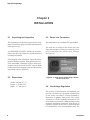
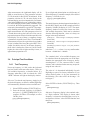
Chapter 1
INTRODUCTION
1.1 Purpose
The 1693 RLC Digibridge™ is a microprocessorcontrolled, automatic, programmable RLC measuring
instrument that provides high accuracy, convenience,
speed , and reliability at low cost. Limit comparison,
binning, and internal bias are provided; both test frequency and voltage are selectable. With an interface
option, the Digibridge tester can communicate with
other equipment via IEEE-488 bus and respond to
remote control.
The versatile, adaptable test fixture, lighted keyboard,
and informative display panel makes the Digibridge
tester convenient to use. Measurement results are
clearly shown with decimal points and units, which
are automatically presented to assure correctness.
Display resolution is 5 full digits for R, L, C, G,
Z, and Y (4 full digits for D, Q, R, X, B, and ANG.
Notice that R is also known as ESR (equivalent series
resistance).
The basic accuracy is 0.02%. Long-term accuracy and
reliability are assured by the measurement system,
which makes these accurate analog measurements
over many decades of impedance without any critical
internal adjustments. Calibration to account for any
change of test-fixture parameters is semiautomatic;
the operator needs to provide only open-circuit and
short- circuit conditions in the procedure. The
Digibridge tester normally autoranges and automatically identifies the principal measurement parameter.
Introduction
The optional test fixture 1689-9600, with a pair of
plug-in adaptors, receives any common component
part (axial-lead or radial-lead), so easily that insertion
of the device under test (DUT) is a one-hand operation. True 4-terminal connections are made automatically. Extender cables are available for measurements
at a moderate distance from the instrument.
Limit comparisons facilitate sorting into 13 GO and
2 NO-GO bins.
• Test frequencies from 12 Hz to 200 kHz
• Test voltages from 5 mV to 1.275 V; bias (2 V)
• Delay (before data acquisition) from zero to
99999 ms
• Measurement speeds up to 30 per second
• Multi-measurement routines with automatic
averaging and/or median taking of 2 to 255
measurements.
• Displays: measured values , percentages, differences, ratios, GO/NO-GO, binning
• Automatic output of value , bin number, bin
summary and other results via IEEE-488 bus
Bias can be applied to capacitors being measured,
either by programming the selection of an internal
supply (2 V) or by sliding a switch to connect an
external voltage source (up to 60 V).
A choice between two interface options provides full
“talker/listener” and “talker only” capabilities consistent with the standard IEEE-488 bus . (Refer to the
IEEE Standard 488-1978, Standard Digital Interface
for Programmable Instrumentation.)
1
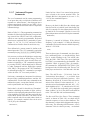
1693 RLC Digibridge
1.2 General Description
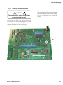
1.2.1 1693 RLC Digibridge Overview
The basic features of the 1693 are provided on the
vertical front panel. These include the keypad, display, and the power OK/OFF button. The set of four
bnc connectors for connection to the test fixture is
supplied on the front panel, but can be relocated to
the rear if that is preferred. The display-panel and
keyboard indicators serve to inform and guide the
operator in manipulating the simple controls, or to
indicate that remote control is in effect.
The 1693 instrument also stands on a table or bench,
where the bail provided under its front edge can be
used to tilt it back for operator convenience . This
model goes particularly well in a rack , with its vertical front panel and cable connection (from either
front or rear) to a suitable test fixture. The sturdy
metal cabinet is durably finished, in keeping with the
long-life circuitry inside. Glass-epoxy circuit boards
interconnect and support high-quality components to
assure years of dependable performance.
1.2.2 References
Electrical and physical characteristics are listed in
Specifications at the front of this manual. Interface
connections and instrument dimensions are given in
Installation, Chapter 1. Controls are described below
in Chapter 1; their use, in Operation, Chapter 3. A
functional description is given in Theory, Chapter 4.
1.3 Controls, Indicators, and
Connectors
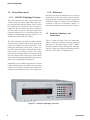
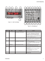
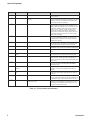
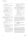
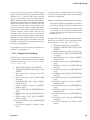
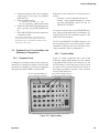
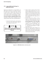
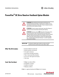
Figure 1-1 shows the front of the 1693 instrument.
Figure 1-2 shows the display on the front panel and
and Figure 1-3 shows the controls. Table 1-1 identifies them with descriptions and functions. Similarly,
Figure 1-4 shows the controls and connectors on the
rear of the 1693. Table 1-2 identifies them.
Adaptability to any common ac power line is assured
by the removable power cord and the convenient line
voltage switch. Safety is enhanced by the fused isolating power transformer and the 3-wire connection.
Figure 1-1: 1693 RLC Digibridge, front view
2
Introduction
1693 RLC Digibridge
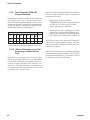
1
6
2
3
5
8
11
10
9
13
14
15
7
20
19
18
12
17
16
4
Figure 1-2: 1693 Front Display
Figure 1-3: 1693 Keyboard
Reference
Description
Function
1
RLCGZY Display
Name
Digital display, 5 numerals with decimal points
and negative sign (-) when applicable.
Display of the principal measured value. If function is
MEASURE and display section is VALUE, Number indicates
R, L, C, G, Z, or Y. If display selection is delta% or delta
RLC, indicates percentage difference or value difference
respectively of R, L, C, G, Z, or Y compared to stored
nominal value. If display selection is BIN NO., indicates bin
assignment is measured DUT. If function is ENTER, displays
are indications of programmed entries, special functions, bin
sum, status in calibration sequences, etc.
2
Units and multipliers
LED indicators
Indicates measurement units associated with the primary
and secondary display. Indicates “%” if display selection is
delta%. Indicates “PPM” if Q or D display selection is parts
per million.
3
QDRXBAng Display
Digital display, 5 numerals with decimal points
and negative sign (-) when applicable.
If function is MEASURE, display of secondary measured
value of if display is BIN NO. blank.
If function is ENTER, RLC, QDR display together indicate
programmed entries, special functions, status in calibration
sequences, etc.
4
POWER switch
Pushbutton (push again to release)
Switches the Digibridge ON, button in and Off, button out.
OFF position breaks both sides of the power circuit.
5
Other display panel
indicators
LED indicators
CONST I indicates that a fixed current has been selected.
CONST V indicates that measurement source resistance is
fixed at 25 ohms.
RANGE HELD indicates that the autoranging is disabled.
NOT 1kHz indicates that a frequency other than
1kHz has been selected.
RATIO indicates that the ratio mode has been selected.
6
Selected Parameter
Introduction
LED indicators
Indicated parameter selected for primary and secondary
QDRXBAng display.
3
1693 RLC Digibridge
Reference
Name
Description
Function
7
Keyboard
Group of keys, indicators and 2 other switches
Manual programming and control. Refer to items 7 through
19 for more detail.
8
Programming Keys
Set of 16 keys, generally labeled with black
and gray
Multipurpose input of programming instruction, selections,
and data. Dual purposes of keys are indicated by color: Black
labels apply normally. Gray labels apply immediately after
you press and release the [SHIFT] key.
9
[FUNCTION] key
Indicators MEASURE and ENTER
Selection of function. MEASURE enables measurement
and some routines that cannot be done in ENTER such as
“ZERO” calibrations, keyboard lock or unlock, and part of full
recalibration. ENTER enables programming of all special
functions, current , frequency, voltage, averaging, delay,
nominal value, and binning instructions. Either function
allows selection of hold range, constant voltage, DQ in ppm,
internal bias, parameter, equivalent circuit, measure mode,
measure rate, and display.
10
[DISPLAY] key
Indicators: VALUE, delta%, BIN NO.
Selection of displays for MEASURE function; refer to items
1, 2, and 3 for description of displays. Two indicators are
lit simultaneously for delta RLC. This key has no effect on
ENTER-function displays.
11
[MEASURE RATE] key
Indicators: SLOW, MED, FAST
Selection of measurement speed as indicated. Speed is
also affected by many other choices. Use SLOW for better
accuracy and FAST for increased measurement speed.
12
[MEASURE MODE] key
Indicators: CONT, TRIGGERED
Mode selection: CONT, continuously repeating measurement;
TRIGGERED, single measurement initiated by START button.
13
BIAS ON Indicator
LED indicator
Indicates that internal bias in on, or EXTERNAL BIAS switch
is ON.
14
EXTERNAL BIAS
switch
Slide switch, 2 positions: ON and OFF
To connect and disconnect the external bias circuit. External
bias is applied via rear connector and optional bias cable.
15
GO/NO-GO indicators
Pair of LED indicators
GO means measured value is acceptable, based on the limits
previously stored. NO-GO means RLC or QDR value or
both are unacceptable. Indicator remains lighted during next
measurement.
16
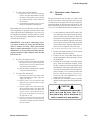
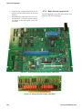
START button
Pushbutton switch
Starts measurement sequence, aborting any measurement
that may be in process. Normally used in TRIGGERED
measurement mode.
17
REMOTE CONTROL
indicator
LED Indicator
Indicates when remote control is established by external
command. Functions only if an IEEE interface option is
installed.
18
EQUIVALENT CIRCUIT
key
Indicators: SERIES and PARALLEL
Selection of equivalent circuit for R/Q, C/D, L/Q or C/R. R/X
is also series, G/B is always parallel, Z/Ang and Y/Ang are
magnitude.
19
SHIFT Key
Key labeled SHIFT
Pressing this shifts the role of any key labeled in both black
and gray FROM the BLACK TO the gray label. Do NOT hold
the [SHIFT] key down, press it first and then the other key.
20
Parameter keys
Set of 4 keys, labeled: R/Q, C/D, L/Q, C/R, R/X
, G/B, Z/Ang, Y/Ang
Selection of principal and secondary measurement
parameters. In the ENTER mode, repeated pushing of any
one parameter key changes the range in sequence 1 2 3 4
…. And hence measurement values.
Table 1-1: Front controls and indicators
4
Introduction
1693 RLC Digibridge
1
3
2
4
5
6
7
8
Figure 1-4: Rear controls and connectors on 1693 Digibridge
Reference
Name
Description
Function
1
EXTERNAL BIAS
Connector
Connector, 2 pins, labeled 60V max, 200mA
max, + -.
For External Bias supply. Optional cable available 16582450. Cable comes with a fuse (2/10 A, 250V, 3AG type, fast
blow).
2
TALK switch*
Toggle switch
Selection of mode of IEEE-488 interface: TALK/LISTEN or
TALK ONLY as labeled.
3
Power Connector
Shrouded 3-wire receptable labeled 90250VAC, 50-60 Hz, 60W MAX.
AC power input
4
Fuse
Fuse in power input module drawer (6/10 A,
250V, 5x20mm, slow blow)
Short-circuit protection. Replace only with the same rating.
To replace, press up on the release tab to remove fuse
drawer.
5
Side Vent
Air passage
Ventilation
6
RS-232 Interface
RS-232 Interface for updating firmware of
IEEE Card
Firmware can be updated using standard RS232 cable and
software from IET.
7
IEEE-488 Interface
connector
Socket, 24-pin. Received IEEE-488 interface
cable.
Input/Output connections according to IEEE-488 standard.
Functions: complete remote control. Output of selected
results with or without PC.
8
Not shown
Vent
Air passage
Ventilation
Internal Fuse
1/4 A, plug-in type, sub-miniature, quick acting.
Protects instrument circuitry from damage by charged
capacitors.
*TALK switch and IEEE connectors are supplied with the IEEE interface option only. Otherwise blank panel is installed.
Table 1-2: Rear controls and connectors
Introduction
5
1693 RLC Digibridge
1.4 Accessories
IET makes several accessories that enhance the
usefulness of each Digibridge. A choice of extender
cables facilitates connection to a parts handler or
to any DUT that does not readily fit the test fixture.
Extender cables are available with your choice of
banana plugs, BNC, or type 874 connectors. Each
cable has 4 separate connectors for true 4-terminal
connections (and guard) to the device being measured, without appreciable reduction in measurement
accuracy. A remote test fixture is available to receive
hand-inserted components at a distance from the
Digibridge
1.4.1 Supplied accessories
• Extender cable, bnc-to-bnc (1-meter long)
• Power cable
• Instruction manual
• Calibration certificate traceable to SI
1.4.2 Optional Accessories
Remote Test Fixture
1689-9600
Kelvin Test Leads
Digibridge Calibration Kit
1689-9604
(Requires Remote Test Fixture: 1689-9600)
bnc-bnc Extender Cable, 2-Meter
1700-03
Alligator Clip Leads, 1 Meter
7000-04
(May also be used as bnc-to-banana-plug connector)
1689-9602-2
Chip Component Tweezers
IEEE Digibridge Interface
7000-05
1689-9640
Rackmount Kit
1689-9611
1657-9600
Banana-Plug Extender Cable
(Requires Remote Test Fixture: 1689-9600)
6
Introduction
Introduction
0.00001 pF to 99999 µF
C
Ratio and DQ in PPM
0.00010 aF to 9999.9 F
0.00010 nH to 9999.9 MH
0.00010 Ω to 9999.9 GΩ
h.
i.
c.
d.
e.
f.
g.
a.
b.
+
-
Model: 1693-9700
CAGE CODE: 62015
IET LABS, INC.
Figure 1-5: Typical operating guide attached to 1693
www.ietlabs.com
• 534 Main Street, Westbury, NY 11590 • (516) 334-5959 • Fax: (516) 334-5988
1693 label/09-20-2012
SN: 9090035011
NA
[SHIFT] [HOLD RNG]
again
Select the desired range then
[SHIFT] [HOLD RNG]
NA
NA
[SHIFT] [CONST V] again NA
[SHIFT] [INT BIAS] again
[SHIFT] [DQ in PPM]
again
[SHIFT] [CONST V]
[SHIFT] [DQ in PPM]
[SHIFT] [DELAY]
[SHIFT] [AVERAGE]
[FUNCTION] [1] [=]
[SHIFT] [AVERAGE]
[FUNCTION] [0] [=]
[SHIFT] [DELAY]
[SHIFT] [VOLTAGE]
[SHIFT] [FREQUENCY]
View Current Setting
NA
NA
Cancel
Observe all safety rules when working with high voltages or line voltages. Connect the (G) terminal to earth ground in order to maintain the case at a safe voltage. Whenever hazardous voltages (>45 V) are used, take all measures to avoid accidental contact with any live components: a) Use maximum insulation and
minimize the use of bare conductors. b) Remove power when adjusting switches. c) Post warning signs and keep personnel safely away.
OFF
NA
OFF
OFF
NA
D and Q in PPM
Default Sample setting adjustment
Programming 400 Hz:
[FUNCTION] [.] [4] [=]
[SHIFT] [FREQUENCY]
Programming 15 mV:
1V
[FUNCTION] [.] [0] [1] [5] [=]
[SHIFT] [VOLTAGE]
Programming 25 measurements:
1
[FUNCTION] [2] [5] [=]
[SHIFT] [AVERAGE]
Programming a delay of
200 ms:
0
[FUNCTION] [2] [0] [0] [=]
[SHIFT] [DELAY]
OFF
[SHIFT] [INT BIAS]
1 kHz
NA
2V
Internal Bias
Hold constant
voltage
Hold constant
range
0 to 99,999 ms
1 to 256
Averaging
Delay
5 mV to 1.275 V
Test voltage
Range
12 Hz to 200 kHz
Parameter
Test frequency
The following programmable functions are available:
a. Select measurement conditions as follows:
• [FUNCTION] key selects MEASURE mode
• [DISPLAY] key selects VALUE, ∆%, or BIN NO
• [MEASURE RATE] key selects SLOW, MEDIUM, or FAST
• [MEASURE MODE] key selects CONTINUOUS or TRIGGERED
• [EQUIVALENT CIRCUIT] key selects SERIES or PARALLEL
b. Select impedance to be measured as follows
• [R/Q] key to show Resistance in the primary display and Quality factor in the secondary display
• [L/Q] key to show Inductance in the primary display and Quality factor in the secondary display
• [C/D] key to show Capacitance in the primary display and Dissipation in the secondary display
• [C/R] key to show Capacitance in the primary display and Resistance in the secondary display
• To select other parameters, press and hold [SHIFT] key and select as appropriate
c. Connect component to be tested to the test terminals as appropriate.
d. If in the TRIGGERED mode, press [START].
Keep hands and objects at least 10 cm (4 in) from test fixture.
If NEG RLC lights, the selected parameter is not appropriate for the DUT and another parameter should be selected. For example, if the Digirbdige is set to measure capacitance, and NEG RLC is lit, that means that the DUT
is inductive.
To view relative measurements, the nominal value and the bin limits must be first programmed. (See section 5 below.)
Once the values have been programmed, select one of the following options by pressing the [DISPLAY] key:
• % difference from the nominal value: ∆% must be lit
• Difference from nominal in original units (pF, mH, etc.): VALUE and ∆% must both be lit
• Assigned bin number: BIN NO must be lit
WARNING
Before making measurements, zero the Digibridge as follows: (Note: For best accuracy, repeat this procedure every day, after each change of frequency, and after any change of test-fixture adaptors.)
Attach extender cables or whichever test fixture/adapter is appropriate.
Create an open circuit by having the spacing between + and - cable ends match the spacing of the DUT
terminals. See the figure.
If the spacing of DUT terminals is unknown, make sure that
Match spacing of
DUT terminals
the + and – ends of the cable are at least 0.75” (19 mm)
apart.
Drive +
Confirm that MEASURE keyboard light is lit.
Press [MEASURE MODE] key to select TRIGGERED mode
Drive +
Drive Press the following keys: [1] [6] [9] [3] [=] [SHIFT] [OPEN].
Drive Press [START] and wait for the green GO light.
Create a short circuit across test terminals by connecting all
Sense +
Sense Sense cable ends together as shown in the figure.
Press the following keys: [1] [6] [9] [3] [=] [SHIFT] [SHORT].
DUT
Press [START] and wait for the green GO light.
Sense +
At this point, the unit should be ready for taking measurements.
If something goes wrong during the zeroing process, the proceOpen
Short
Connection
Connection
dure should be repeated.
3. Obtaining optimal accuracy by zeroing
a. If the Digibridge includes an optional IEEE-488 interface, set [TALK] switch (rear panel) to TALK ONLY (unless instructions are to be received through the IEEE-488 bus).
b. Make sure the [EXTERNAL BIAS] is in the OFF position.
c. Press the [POWER] button.
The unit runs a brief self-check on start-up.
d. Wait until keyboard lights indicate MEASURE, VALUE, SLOW, TRIGGERED, SERIES.
If a fault is detected, measurements are blocked and an error code remains displayed. See manual, paragraph 3.13.
If keyboard lights remain dark, keyboard is locked. To unlock it, see manual paragraph 3.9.
To switch power off, press the [POWER] button.
2. Starting-up
Test frequencies: Over 500 selectable test frequencies ranging from 12 Hz to 200 kHz
Applied voltage: 5 mV to 1.275 V (programmable in 5 mV steps)
Measurement speed: Up to 19 measurements per second
Bias: Internal: 2.0 Vdc; External: 60 Vdc max
Accuracy: Basic RLCGZY: ±0.02%
0.00001 mH to 99999 H
L
Direct Reading Range
0.00001 Ω to 99999 kΩ
R and [Z]
Parameter
Measurement parameters: R/Q, L/Q, C/D (series or parallel), R/X (series), G/B (parallel), Z/Angle or Y/Angle
Ranges:
4. Taking measurements
Operating Guide for Model 1693 RLC Digibridge
1. General Information
The 1693 RLC Digibridge is a microprocessor-controlled, automatic RLC meter.
1693 RLC Digibridge
7
1693 RLC Digibridge
Chapter 2
INSTALLATION
2.1 Unpacking and Inspection
2.3 Power Line Connection
This instrument was carefully inspected before shipment. It should be in proper electrical and mechanical
order upon receipt.
This instrument uses a standard IEC input module.
An OPERATING GUIDE is attached to the instrument to provide ready reference to specifications and
operating information.
The input fuse is located in the drawer above the
input power module. If it has to be replaced, be sure
to use a “slow blow” fuse, 250 V, 6/10 A, 5x20 mm.
See Figure 2-1.
If the shipping carton is damaged, inspect the instrument for damage (scratches, dents, broken parts, etc).
If the instruments is damaged or fails to meet specifications, notify the carrier and IET Labs for RMA
number. Retain the shipping carton and the packing
material for carrier’s inspection.
2.2 Dimensions
Width = 440 mm (17.3”)
Height = 147 mm (5.8”)
Depth = 377 mm (14.8”)
Figure 2-1: Input power module with a drawer
for the input fuse
2.4 Line-Voltage Regulation
The accuracy of measurements accomplished with
precision electronic test equipment operated from
ac line sources can often be seriously degraded by
fluctuations in primary input power. Line-voltage
variations of ±15% are commonly encountered, even
in laboratory environments. Although most modern
electronic instruments incorporate some degree of
regulation, possible power-source problems should
be considered for every instrumentation setup. The
8
Installation
1693 RLC Digibridge
use of line-voltage regulators between power lines
and the test equipment is recommended as the only
sure way to rule out the effects on measurement data
of variations in line voltage.
An external test fixture or cables are always required,
because connection from the 1693 Digibridge to the
DUT is provided via BNC cables (from connectors
that can be positioned at either front or rear of the
instrument, as described .in Chapter 5). For general
purposes, the recommended test fixture, cable, and
their connections are as follows. Refer to paragraphs
1.4 and 3.2 for more information about accessories.
On 1693
Description
Cable
On
IL
Drive -
Black Band
I+
Potential -
Black and
White Band
P+
Potential +
Red and White
Band
P-
Drive +
Red Band
I-
PH
IH
2.6.1 Internal Bias
No external connections are required for the internal
2-volt bias. 2V bias is supplied internally by the
instrument.
2.5 Test-Fixture Connections
PL
2.6 Bias Voltage for the DUT
COMMENT: It is important that the IL and PL leads
connect to the same end of the DUT (and that PH and
IH connect to the other end). Also, connecting IL/PL
to the test-fixture connectors labeled “+” (and IH/PH
to “-”) assures that the test fixture’s “+”and “0” labels
agree with the bias polarity.
2.6.2 External Bias
External bias can be provided by connecting a suitable
current-limited, floating dc voltage source, as follows.
• Be sure that the voltage is never more than
60 V, max.
• A current limiting voltage supply is recommended; set the limit at 200 mA, max.
• Be sure that the bias supply is floating; DO
NOT connect either lead to ground.
• A well-filtered supply is recommended. Biassupply hum can affect some measurements,
particularly if test frequency is the power
frequency.
• Generally the external circuit must include
switching for both application of bias after each
DUT is in the test fixture and discharge before
it is removed.
• Connect the external bias voltage supply and
switching circuit, using the optional 1658-2450
cable, via the rear-panel EXTERNAL BIAS
connector. Observe polarity marking on the rear
panel; connect the supply accordingly.
NOTE: In the cable’s color code, RED is associated
with “hot” leads, which have dc voltage, negative
with respect to ground , when bias is used.
Installation
9
1693 RLC Digibridge
2.7 IEEE-488 Interface
2.7.1 Description
If you have the IEEE Interface option 1689-9640 (see
Figure 2-2), you can use this instrument as part of a
system comprised of other test instruments, printers
and a PC, with each assigned its own bus address. The
simplest system could consist of this instrument and
just a printer. The documentation of each instrument
describes the details of how to communicate with it,
and how it communicates with other instruments, as
appropriate.
Figure 2-2: IEEE-488 interface
All instruments are inter-connected using standard
IEEE-488 cables, in nearly any combination of hub
and daisy-chain connections, subject only to lengthof-run restrictions. Standard IEEE-488 connectivity
uses a 24-pin connector carrying 16 signal lines plus
several ground connections and a shield.
This instrument will function as either TALK/
LISTEN or a TALK ONLY device in the system, depending on the position of the TALK switch. “TALK/
LISTEN” denotes full programmability and is suited
for use in a system that has a controller or computer
to manage the data flow. The “handshake” routine assures that the active talker proceeds slowly enough for
the slowest listener that is active, but not limited by
any inactive (unaddressed) listener. “TALK” is suited
to a simpler system -- e.g. Digibridge and printer -with no controller and no other talker. Either mode
provides measurement results to the active listeners
in the system.
2.7.3 Codes and addresses
General. The device-dependent messages, such as instrument programming commands and measurement
data (which the digital interface exists to facilitate),
have to be coded in a way that is compatible between
talkers and listeners . They have to use the same
language. Addresses have to be assigned, except in
the case of a single “talker only” with one or more
“listeners” always listening. The Standard sets ground
rules for these codes and addresses.
In this instrument, codes for input and output data
have been chosen in accordance with the IEEE-488.2
rules . The address (for both talker and listener functions) is user selectable, as explained below.
Instrument Program Commands. The set of commands used in remote programming is an input
data code to which the instrument will respond as a
“talker/listener”, after being set to a remote code and
addressed to listen to device-dependent command
strings. The set includes all of the keyboard functions except switching external bias ON/OFF and full
recalibration, which are not remotely programmable.
Refer to paragraph 3.11.7 for a table of the commands
used in programming.
Address. The initial setting of address,, provided by
the factory, is binary 00011, decimal 3. Consequently,
the talk address command (MTA) is C in ASCII code
and, similarly, the listen-address command (MIA) is
#. If a different address pair is desired, set it manually
using the following procedure.
2.7.2 Signal Identification
For a key to signal names, functions, and pin numbers. Further explanation is found in the IEEE-488.2
Standard.
10
Installation
1693 RLC Digibridge
WARNING
Shock hazard and static electricity
can cause damage.
Disassembly should be preformed by
qualified personnel only.
1. Take the Digibridge to a qualified electronic
technician who has the necessary equipment
for minor disassembly and adjustment. Have
the electronic technician remove the interface
option assembly, as described in his 1693
Digibridge Service instructions.
There is no need to remove the top cover first.
2. Have the electronic technician set the
switches in “DIP” switch assembly S2 to
the desired address, which is a 5-bit binary
number. (See below.)
Figure 2-3: DIP switch set to Decimal Address 3
3. Have the electronic technician replace the
interface option assembly in its former place.
Notice that S2 is located at the end of the
interface option board, about 3 cm (1 in.)
from the TALK switch S1.
If S2 is covered
A. Lift the cover off, exposing the “DIP”
switch, which has 5 tiny switches, numbered 1 thru 5.
B. To enter logical 1’s, depress the side of
each switch nearest the end of the board
(switch open).
C. To enter logical 0’s, depress the other side
of the switch (switch closed). The address
is read from 5 to 1.
Thus, for example, to set up the address 00011,
enter 0’s at positions 5, 4, 3; enter l ‘s at
positions 2 and 1. (This makes the talk address
“C” and the listen address “#”.)
Strictly speaking, the address includes more; S2
determines only the device-dependent bits of the
address. You cannot choose talk and listen addresses
separately, only as a pair. The list of possible pairs is
shown in Table 2-1.
The GPIB Address of the Digibridge is set by the
SW2 DIP Switch. The numeric value is set by setting
the switch on or off for the corresponding bit with
the OFF position for binary 1 and ON position for
binary 0. Depress the rocker toward the OFF marking for OFF and toward the numeric marking for the
corresponding ON position.
Switch Settings
Decimal
Address
S1
S2
S3
S4
S5
0
ON
ON
ON
ON
ON
1
OFF
ON
ON
ON
ON
2
ON
OFF
ON
ON
ON
3
OFF
OFF
ON
ON
ON
4
ON
ON
OFF
ON
ON
5
OFF
ON
OFF
ON
ON
6
ON
OFF
OFF
ON
ON
7
OFF
OFF
OFF
ON
ON
8
ON
ON
ON
OFF
ON
9
OFF
ON
ON
OFF
ON
10
ON
OFF
ON
OFF
ON
11
OFF
OFF
ON
OFF
ON
12
ON
ON
OFF
OFF
ON
13
OFF
ON
OFF
OFF
ON
14
ON
OFF
OFF
OFF
ON
15
OFF
OFF
OFF
OFF
ON
16
ON
ON
ON
ON
OFF
17
OFF
ON
ON
ON
OFF
18
ON
OFF
ON
ON
OFF
19
OFF
OFF
ON
ON
OFF
20
ON
ON
OFF
ON
OFF
21
OFF
ON
OFF
ON
OFF
22
ON
OFF
OFF
ON
OFF
23
OFF
OFF
OFF
ON
OFF
24
ON
ON
ON
OFF
OFF
25
OFF
ON
ON
OFF
OFF
26
ON
OFF
ON
OFF
OFF
27
OFF
OFF
ON
OFF
OFF
28
ON
ON
OFF
OFF
OFF
29
OFF
ON
OFF
OFF
OFF
30
ON
OFF
OFF
OFF
OFF
31
Not Used
Table 2-1: IEEE-488 address settings
Installation
11
1693 RLC Digibridge
In the above example, the remote message codes:
MLA and MTA are X0100011 and X1000011, respectively. Thus, the listen address and the talk address are
distinguished, although they contain the same set of
device-dependent bits, which you set into S2.
Data Output: Data (results of measurements) are
provided on the D10l...D107 lines as serial strings
of characters. Each character is a byte, coded according to the 7-bit ASCII code, as explained above.
The alphanumeric characters used are appropriate to
the data, for convenience in reading printouts. The
character strings are always provided in the same
sequence as that tabulated in paragraph 3.11.13; for
example: RLC value, QDR value, bin number - if all
3 were selected (by the X7 command). The carriagereturn and line-feed characters at the end of each
string provide a printer (for example) with the basic
commands to print each string on a separate line.
For example, if the measurement was 0.54321 μF
(1 kHz, range 4 held), the character string for RLC
value is:
U(space)C(space)μF(2 spaces)0.54321(CR)(LF)
If the D measurement was .001, the character string
for QDR value is:
(2 spaces)D(5 spaces)00.00l0(CR)(LF)
If the measurement falls into bin 9, the character string
for bin number is:
F(space)BIN(2 spaces)9(CR)(LF)
The character string for RLC value has the length of
17 characters; for QDR value, 17 characters; for bin
number, 10 characters - including spaces, carriagereturn, and line-feed characters. Refer to the format
tables in Section 3.11.12 for details.
12
2.8 Environment
The Digibridge can be operated in nearly any environment that is comfortable for the operator. Keep the
instrument and all connections to the parts under test
away from electromagnetic fields that may interfere
with measurements.
Position the instrument with consideration for ample
air flow to the side and rear ventilation holes. The
recommended space around the instrument is at least
3” (75 mm). The surrounding environment should be
free from excessive dust to prevent contamination of
electric circuits.
Refer to the Specifications at the front of this manual
for temperature and humidity tolerances. To safeguard
the instrument during storage or shipment, use protective packaging. Service personnel refer to Section 5.
When the Digibridge is mounted in a rack or other
enclosed location, make sure that the ambient temperature inside the rack does not exceed the limits
specified under ‘’Environment’’ in the Specifications
at the front of this manual, and that air can circulate
freely past all air inlet and outlet vents.
2.9 Rack Mount Option
To rack mount the unit, place the instrument on the
shelf (1689-9611) so that its feet drop through the
large holes.
Then position this assembly in the rack as desired
and secure with four 10-32 screws. If the rack does
not have threaded holes, use the supplied clip nuts.
Installation
1693 RLC Digibridge
Chapter 3
OPERATION
3.1 Basic Operation
3.1.1 Overview
For initial familiarization with the Digibridge™ RLC
tester, follow the procedure carefully. After that, refer
back to this section as required. Condensed operating
instructions are provided near the front of this manual
as well as on the unit itself.
3.1.2 Startup
CAUTION
Before the unit is powered up, the
internal temperature of the Digibridge
must be above 0°C. Otherwise, the
instrument may be damaged by
thermal shock.
5. (To turn the instrument off, push and release
the POWER button and leave it in the “out”
position.)
6. Wait until keyboard lights indicate
MEASURE, VALUE, SLOW, CONT (or
TRIGGERED), SERIES. If they do not, there
are two possible explanations: self-check
fault and keyboard lock.
If a fault is detected in the self-check, measurements
are blocked and an error code remains displayed.
Under some conditions, the block to operation can
be bypassed. (See paragraph 3.13.) If the keyboard is
locked, all of those keyboard indicators remain unlit
except MEASURE and/or REMOTE CONTROL and all previously programmed test conditions, limits,
etc are reestablished. To unlock it , see paragraph 3.9.
1. Plug in the unit.
2. If the Digibridge tester includes an optional
IEEE-488 interface, set TALK switch (rear
panel) to TALK ONLY (unless instructions
are to be received through the IEEE-488
bus) .
3. Switch EXTERNAL BIAS OFF (front
panel).
4. Press -the POWER button “in”, so that it
stays in the depressed position.
Self-check codes will show briefly, indicating that the
instrument is automatically executing a power-up
routine that includes self checks.
Operation
13
1693 RLC Digibridge
3.1.3 Zeroing
In the zeroing process, the instrument automatically measures stray parameters and retains the data,
which it uses to correct measurements so that results
represent parameters of the DUT alone , without (for
example) test-fixture or adaptor capacitance.
Before measurement, zero the Digibridge as follows.:
1. Set conditions: SLOW measure rate, 1 V test
voltage (default), RANGE HELD indicator
NOT lit.
2. To measure open circuit
A. Press [FUNCTION] key (if necessary) to
select MEASURE function.
B. Press [MEASURE MODE] key (if necessary) to select TRIGGERED mode.
C. Connect the remote test fixture or at least
the BNC cables and adaptors that will
contact the DUT.
D. Be sure that the test fixture is open
circuited.
If you want this “zero” process to echo a display of
0 00000 , press the [C/D] key. However doing so will
disable automatic parameter selection. (See paragraph
3.1.4, step 2.).
E. Press the following keys: [l] [6] [9] [3] [=]
[SHIFT] [OPEN]
Note: the GO indicator being lit and two zeros confirm
the previous step. Watch the GO indicator on the
keyboard; not one on any remote test fixture.
F. Keep hands and objects at least 10 cm
(4 in.) from test fixture.
G. Press the START button.
3.1.3.1 Zeroing with various test
fixtures
This section contains information on proper open and
short connections for various types of cables for use
with the 1693 Digibridge.
7000-04 Banana and 1657-9600 Extender Cables
Open and short should be performed as shown in
Figure 3-1 below when using banana plugs. When
performing Open the spacing between the pairs should
be the same as the spacing of the terminals on the DUT
or if unknown a minimum of 0.75”. Short should be
performed as shown and it is important to keep senses
and drives in the correct order.
Geometry:
If is important to maintain the spacing between the
leads during the open compensation at exactly the
same distance as the spacing is when the banana plugs
are connected to the DUT. If the spacing is not exactly
the same there will be an error in the measured value.
This is due to the fact that the four terminal Kelvin
connection stops at the connection between Drive
and Sense. The banana plugs are two-terminal so the
capacitance between the parallel spaced banana plugs
will be measured as part of the overall measurement
unless open compensation is performed to eliminate
this additional capacitance.
The GO indication disappears.
Match spacing of
DUT terminals
H. Wait for the GO indicator to be lit again.
3. To measure short circuit:
A. Short the fixture with a clean copper wire
(AWG 18 to 30), length 5 to 8 cm.
B. Press the following keys: [l] [6] [9] [3] [=]
[SHIFT] [SHORT].
Note : the GO indicator being lit and two fives confirm the
previous step.
C. Press the START button.
The GO indication disappears.
D. • Wait for the GO indicator to be lit again.
E. • Remove the short circuit.
Note: For best accuracy, repeat this procedure daily
and after changing test-fixture adaptors or frequency..
14
Drive +
Drive +
Drive -
Sense +
Sense +
DUT
Drive -
Sense -
-
Sense +
Open
Connection
Short
Connection
Figure 3-1: Open and short measurements with
banana plugs
Operation
1693 RLC Digibridge
1700-03 Kelvin Cables
Open and short should be performed as shown in
Figure 3-2 below when using Kelvin cables. When
performing an open jaws of clips must be closed.
During short it is important to match drives and sense
exactly as shown.
Open Connection
Short Connection
Figure 3-2: Open and short measurements with
Kelvin cables
1689-9602 and 1689-9602-2 bnc-to-bnc Cables
with bnc-T
Open and short should be performed as shown in
Figure 3-3 below when using bnc-to-bnc cables
with bnc-T connectors. During short connection two
Pomona 3283 bnc (F)-(F) adapters are used to connect
potential together and drives together.
Open Connection
Geometry:
If is important to maintain the spacing between the
leads during the open compensation at exactly the
same distance as the spacing is when the banana plugs
are connected to the DUT. If the spacing is not exactly
the same there will be an error in the measured value.
This is due to the fact that the four terminal Kelvin
connection stops at the connection between Drive
and Sense. The banana plugs are two-terminal so the
capacitance between the parallel spaced banana plugs
will be measured as part of the overall measurement
unless open compensation is performed to eliminate
this additional capacitance.
Short Connection
Figure 3-3: Open and short measurements with
bnc-to-bnc cables
Operation
15
1693 RLC Digibridge
1689-9602 and 1689-9602-2 bnc-to-bnc Cables
with bnc-T and GR874 Connectors
Open and short should be performed as shown in
Figure 3-4 below when using bnc-to-bnc cables with
bnc-T connectors and the GR874 adapters. During
short connection connect the two GR874 connectors
together. During open compensation spacing similar
to the DUT or at least 0.75” should be maintained to
minimize capacitance between the GR874 connectors.
Geometry:
If is important to maintain the spacing between the
leads during the open compensation at exactly the
same distance as the spacing is when the banana plugs
are connected to the DUT. If the spacing is not exactly
the same there will be an error in the measured value.
This is due to the fact that the four terminal Kelvin
connection stops at the connection between Drive
and Sense. The banana plugs are two-terminal so the
capacitance between the parallel spaced banana plugs
will be measured as part of the overall measurement
unless open compensation is performed to eliminate
this additional capacitance.
7000-05 Tweezers
The small amounts of residual-tip resistance and
inductance can be automatically corrected by using
the Digibridge shorting function with the tips pressed
together. Guard shields between the tweezer blades
minimize capacitance between them. A correction for
this small capacitance can be made using Digibridge
open circuit test with the tips held at a spacing equal
to that of the component’s contact spacing.
Measurement accuracy is very sensitive to connection
geometry. The same connection geometry must be
used for open/short compensation as for connection
to the device under test.
Figure 3-5: Chip component tweezers
1689-9600 Test Fixture
Ideally zeroing with the 1689-9600 should be performed with the 1689-9604 Digibridge Calibration
kit.
Open Connection
The alternate method for performing open and short
using two 18 AWG bus wires for the open and one
loop of 18 AWG bus wire for a short. Two wires
should be used to perform an open to ensure that the
pairs of contacts in the 1689-9600 are connected. See
Figure 3-6 below.
Short Connection
Figure 3-4: Open and short measurements with
GR874 connectors
16
Operation
1693 RLC Digibridge
18 AWG
bus wire
18 AWG
bus wire
1689-9600 Test Fixture
Open Circuit
18 AWG
bus wire
1689-9600 Test Fixture
Short Circuit
Figure 3-6: Open and short measurements in
1689-9600
3.1.4 Routine Measurement
1. Verify or select measurement conditions as
follows (indicated by keyboard lights); press
the adjacent key to change a selection.
• Function: MEASURE ([FUNCTION]
key), a necessary selection
• Display: VALUE ([DISPLAY] key), for
normal RLC/QDR results
• Measure rate: SLOW ([MEASURE
RATE] key). for best accuracy
• Measure mode: TRIGGERED
([MEASURE MODE] key), optional
• Equivalent circuit: SERIES
([EQUIVALENT CIRCUIT] key) - see
paragraph 3.3.
If you are in doubt about how to connect the device to
be tested with the Digibridge, refer to paragraph 3.2,
below.
2. To measure any passive component (without
knowing whether it is essentially a resistor,
inductor, or capacitor), use “automatic parameter selection”.
This feature is provided at power-up and remains
enabled as long as you do NOT select any particular
parameter. (Automatic parameter selection can be
disabled by pressing the [C/D] key, for example. Once
disabled, this feature can be enabled again by selecting
the ENTER function and then pressing these keys:
Operation
[l]=[SHIFT][SPECIAL][7]
3. Place DUT in test fixture. Press START. (See
note below.)
The RLC display and units indicator show the principal
measured value and the basic parameter, thus identifying
the DUT. The QDR display shows the measured Q if the
principal units are ohms or henries; the measured 0 if
they are farads.
4. To measure G and D of a Capacitor (C
Range .00001 pF to 99999 µF, 0 range .0001
to 9999):
A. Press [C/D].
B. Place capacitor in test fixture.
C. Press START.
The RLC display shows Cs (series capacitance) and
units (µF, nF, pF); the QDR display shows D (dissipation
factor). {If RLCGZY is negative, the DUT is inductive.}
5. To measure C and R of a Capacitor (C Range
.oooo1 nF to 99999 µF, R range .0001 ohm
to 9999 kilohm):
A. Press [C/R].
B. Place capacitor in test fixture.
C. Press START.
The RLC display shows Os (series capacitance) and
units (µF, nF); the QDR display shows Rs (equivalent
series resistance) and units (ohms, kilohms). {If
RLCGZY is negative, DUT is inductive.}
6. To measure L and Q of an Inductor (L range
.00001 mH to 99999 H, Q range .0001 to
9999):
A. Press [L/Q].
B. Place inductor in test fixture.
C. Press START.
The RLC display shows 15 (series inductance) and units
(mH, H); the QDR display shows Q (quality factor). {If
RLCGZY is negative, DUT is capacitive.}
7. To measure R and Q of a Resistor (R range
.00001 ohm to 99999 kilohms, Q range .0001
to 9999):
A. Press [R/Q].
B. Place resistor in test fixture,
C. Press START.
The RLC display shows Rs (series resistance) and units
(ohms, kilohms); the QDR display shows Q (quality
factor). {If QDRXBAng is negative, DUT is capacitive; if
not DUT is inductive.}
17
1693 RLC Digibridge
8. To measure R and X of a component (R range
.00001 Ω to 99999 kΩ, X range .0001 Ω to
9999 kΩ):
3.2 Connecting the DUT
3.2.1 Overview
A. Press [SHIFT][R/X].
B. Place component in test fixture.
C. Press START.
A. Press [SHIFT][Z/ANG].
B. Place component in test fixture
C. Press START.
The RLCGZY display shows Z (impedance) and units
(ohms, kohms); the QDRXBAngle display shows Angle
and units (degrees). {If QDRXBAngle is negative, DUT
is capacitive.}
11. To measure Y and Angle of a component (Y
range .00001 µS to 99999 S, Angle range
.0001° • to 180º):
A. Press [SHIFT][Y/ANG].
B. Place component in test fixture.
C. Press START.
Connect the “device under test” (DUT), whose parameters are to be measured, as outlined in the next
sections.
3.2.2 The 1689-9600 Remote Test
Fixture (with 1689-9602 BNC
Cable)
Connection of the DUT at a remote test fixture normally requires:
• Remote Test Fixture 1689-9600, or equivalent
fixture or cable
• BNC Cable Assembly 1689-9602 - supplied
with 1693 Digibridge
EXTERNAL
BIAS
On
Off
GO
R
L
C
G
Z
Y
Q
D
1191.7
The RLCGZY display shows Y (admittance) and units
(µS, mS, S); the QDRXBAngle display shows Angle and
units (degrees). {If QDRXBAngle is negative, DUT is
inductive.}
uF
nF
pF
IL
X
B
H
uS
PH
S
mS
k
DE
G
PPM
ANG
CONST I.
NO
GO
CONST V.
RANGE
HELD
NOT 1kHz
START
RATIO
On
IH
POWER
R/Q
L/Q
C/D
REMOTE
CONTROL
C/R
SER PAR
Off
1689-9602
IL
mH
PL
R
.0002
PL
IL
NOTE: This procedure is basic; there are many alternatives described later. You can select and program for
other equivalent circuits, types of results displayed,
test conditions, measurement rate, and bin sorting, etc.
BIA
S
ON
1693 RLC DigiBridge TM
I
+
P
+
P
-
IH
10. To measure Z and Angle of a component (Z
range .00001 ohms to 99999 kohms, Angle
range .0001 • to 180’ ):
NOTE: Clean the leads of the DUT if they are noticeably Dirty, even though the test-fixture contacts will
usually bite through a film of wax to provide adequate
connections. 3-4
IH
The RLCGZY display shows (parallel conductance)
and units ( µS, mS, S); the QDRXBAngle display shows
B (parallel susceptance) and units (µS, mS, S). {If
QDRXBAngle is negative , DUT is inductive.}
PH
A. Press [SHIFT][G/B].
B. Place component in test fixture .
C. Press START.
Charged capacitors can be
dangerous, even lethal. Never handle
their terminals if they have been
charged to more than 60 V. Routine
discharging procedures may not be
perfectly dependable.
PH
9. To measure G and B of a component (G range
.00001 µS to 99999 S, B range .0001 µS to
9999 S):
DANGER
PL
The RLCGZY display shows R (series resistance) and
units (ohms, kohms); the QDRXB Angle display shows
X (series reactance) and units (ohms, kohms). {If
QDRXBAngle is negative, DUT is capacitive.}
I
-
WARNING: SHOCK HAZARD
HIGH VOLTAGE MAY APPEAR ON LEADS AND TERMINALS
GenRad
Formerly made by
1689-9600 REMOTE TEST FIXTURE
Note: The H connectors on the cable are deliberately
connected to the “-” terminals on the test fixture and
vice versa.
Figure 3-7: Connecting remote test fixture to
RLC Digibrige
18
Operation
1693 RLC Digibridge
This remote test fixture provides that true “Kelvin”
connections are made at the points of contact with the
DUT leads. The recommended cable should be used
(rather than any randomly chosen BNC patch cords)
because the known cable parameters enable you to
make corrections for best accuracy. Install the remote
test fixture as follows.
1. Remove any adaptors, cables, etc, if present,
from the DUT port of the instrument.
2. Connect the BNC cable assembly to the
Digibridge and to the remote test fixture as
indicated in Table 3-1.
Note that red designates leads that may be “hot”. (When
bias is applied, they carry the negative voltage with
respect to ground.)
On 1693
IL
PL
PH
IH
Bias
Polarity
Description
1689-9602
On
Cable
1689-9600
+
Drive -
Black Band
I+
+
Potential -
Black and
White Band
P+
-
Potential +
Red and
White Band
P-
-
Drive +
Red Band
I-
Figure 3-8: 1689-9600 Remote Test Fixture
3.2.3 Using the Test-Fixture Adaptors
for Axial-Lead DUT
If the DUT is an axial-lead component or has leads
at opposite ends, insert the leads into the test-fixture
adaptor’s slots as shown in Figure 3-9. Install the testfixture adaptors as shown below; put one in each slot
of the test fixture, by pushing vertically downward.
Slide the adaptors together or apart so the body of the
DUT will fit easily between them.
Table 3-1: Connection of Remote Test Fixture
to 1693 with 1689-9602 cable.
3. Before making measurements, be sure to repeat the zeroing procedure (open circuit and
short circuit), as described in paragraph 3.1.3.
For notes on cable and fixture capacitance and zeroing,
see paragraph 3.1.3, below.
4. If the DUT is a radial-lead component or has
parallel leads at one side, insert them into
the Digibridge remote test-fixture slots as
described below.
The test fixture provides convenient, reliable, guarded
4-terminal connection to any common radial-lead or
axial-lead component part (using adaptors, 16575995). an axial-lead component part. The slots in the
test fixture accommodate wires with diameters from
0.25 mm (.01 in., AWG 30) to 1 mm (.04 in., AWG
18), spaced from 4 to 98 mm apart (0.16 to 3.9 in.)
or equivalent strip conductors. Each “radial” wire
must be at least 4 mm long (0.16 in.). The divider
between the test slots contains a shield , at guard
potential, with its edges semi-exposed. The tapped
holes (6-32 thread) at the left and right ends of the
test fixture are also grounded, to connect the shields
of extender cables.
Operation
Figure 3-9: 1689-9600 Remote Test Fixture with
1657-5995 Test Clips
Note that the contacts inside the adaptor are off center;
be sure to orient the adaptors so the contacts are close
to the body of the DUT, especially if it has short or
fragile leads.
The adaptors accommodate wires with diameters up
to 1.5 mm (.06 in ., AWG 15). The body of the DUT
that will fit between these adaptors can be 80 mm long
and 44 mm diameter (3.1 x 1.7 in.) maximum. Each
19
1693 RLC Digibridge
“axial” wire must be at least 3 mm long (0.12 in.].
The overall length of the DUT, including the axial
wires must be at least 22 mm (0.866 in.).
Insert the DUT so that one lead makes connection on
the left side of the test fixture, the other lead on the
right side. Insertion and removal are smooth, easy
operations and connections are reliable if leads are
reasonably clean and straight. Press the DUT down
so that the leads enter the slots in the adaptors as far
as they go easily.
Be sure to remove any obvious dirt from leads before
inserting them. The test-fixture contacts will wipe
through a film of wax, but can become clogged and
ineffectual if dirty leads are inserted repeatedly. Be
sure to insert only one thing into each half of the test
fixture, at anyone time. (If any object is inserted into
the same slot with a DUT lead, it will probably NOT
make true “Kelvin” connections.)
Figure 3-10: Banana plugs on the 1657-9600
cable
BIA
S
ON
1693 RLC DigiBridge TM
NOTE: For a DUT with very short leads, it is important to orient each adaptor so that its internal contacts
(which are off center) are close to the DUT. To remove
each adaptor, lift with a gentle tilt left or right (never
forward or back) .
L
C
G
Z
Y
Q
D
1191.7
pF
PL
B
H
uS
PH
S
mS
DE
G
k
PPM
ANG
CONST I.
NO
GO
CONST V.
RANGE
HELD
NOT 1kHz
START
RATIO
On
IH
R/Q
L/Q
POWER
C/D
REMOTE
CONTROL
C/R
SER PAR
Off
1689-9602
IL
PL
IL
mH
X
IH
nF
R
.0002
PH
uF
I
+
P
+
P
-
IH
PH
PL
IL
20
On
Off
GO
R
3.2.4 1657-9600 Banana Plug
Extender Cable
The 1657-9600 is a male banana plug extender cable
with shielded 4-terminal Kelvin connections and
guard (3 feet in length) for connecting to 1659, 16899700, 1692 Digibridges and 1689-9600 Remote Test
Fixture. Terminated with 5 banana plugs and includes
5 alligator clip. Each banana plug has a different color
banana plug, red for high and black for low. White
bands for potentials and green band for ground see
Figure 3-10 below.
EXTERNAL
BIAS
I
-
GND
IH
WARNING: SHOCK HAZARD
HIGH VOLTAGE MAY APPEAR ON LEADS AND TERMINALS
PH
1657-9600
GenRad
Formerly made by
1689-9600 REMOTE TEST FIXTURE
PL
1657-9600
IL
Note: The H connectors on the 1689-9602 cable are
deliberately connected to the “-” terminals on the test
fixture and vice versa.
Figure 3-11: Connecting remote test fixture and
the Extender cable to RLC Digibrige
Operation
1693 RLC Digibridge
3.2.5 The 1689-9602 Extender Cable
with bnc-to-Banana-Plug
Adaptors
To connect to DUT’s that are multi-terminal, physically large, or otherwise unsuited for remote test
fixtures, connect bnc-to-banana-plug adaptors to the
extender cable (See Figure 3-12). This is particularly
convenient for DUT’s with binding posts. This accessory cable (1689-9602), as well as the Pomona 1894
and 4684 adaptors, are available from IET Labs. Also
see 7000-04 Alligator Clip Leads.
3.2.6 The Effects of Cable and
Fixture Capacitances
It is important to use very low-capacitance shielded
wire for cables, not only for accuracy, but also to
minimize resonance effects in the measurement of
large inductance at high frequency.
The Capacitance that are Most Liable to Affect
Accuracy. Any test fixture extension cable adds a
bit of capacitance in parallel with the DUT (because
shielding of the leads is imperfect) and more between
each terminal and ground. The zeroing process
(Section 3.1.3) will compensate fully for the capacitances between cables in any normal test setup.
However, capacitance between ground and the “low”
connections at the DUT (C from ground to IL and C
from ground to PL , in parallel, designated Csn) can
affect measurement accuracy of very-high-impedance
DUTs at high frequencies.
Figure 3-12: 1689-9602 Extender Cable with
bnc-to-banana-plug adapters
To use this cable with the adaptors, proceed as
follows:
1. Connect 1689-9602 bnc cable to the 1693
Digibridge as specified in Table 3-1 on page 19.
2. Connect the set of four bnc-to-banana-plug
adaptors to the free ends of the cables. One
of these adaptors has a “pigtail” for connecting GUARD.
3. Zero the Digibridge. (See Section 3.1.3 on
page 14.)
4. Connect the banana plugs (and GUARD, if
appropriate) to the DUT.
Zeroing. Be sure to repeat either the entire power-up
procedure or at least the open-circuit and short-circuit
zeroing procedure after any change in test fixtures or
their cable connections.
Calculating the Capacitance Loading Error. The error
due to this capacitance Csn is designated Ald (“additional error due to loading”). The magnitude of Ald
can be calculated so that you know how significant
it is and so that measurements can be corrected if
desired. Refer to paragraph 3.6.7.
CAUTION
Avoid contact between the shells
o f b n c c o n n e c t o rs . O t h e r w i s e ,
measurements at high test
frequencies may have errors that
result from the changing mutual
inductances between cable shields.
Operation
21
1693 RLC Digibridge
3.2.7 7000-05 Tweezers
The 7000-05 tweezers combine the two functions:
• They handle chip components, up to 0.5 in.
(12 mm) thick.
• Serve as a test fixture for measuring these components, if their terminals are on opposite faces.
The 7000-05 Chip Component Tweezers can handle
small unleaded “chips” or SMDs (surface mounted
devices), passive sensors, and components for testing on the Digibridge. A four-terminal Kelvin connection extends to the tip of the tweezers where the
measurement becomes two-terminal, therefore series
impedance of the connecting cables and internal
tweezer connections do not affect the measurement.
The small amounts of residual-tip resistance and
inductance can be automatically corrected by using
the Digibridge shorting function with the tips pressed
together. Guard shields between the tweezer blades
minimize capacitance between them. A correction for
this small capacitance can be made using Digibridge
open circuit test with the tips held at a spacing equal
to that of the component’s contact spacing.
Figure 3-13: 7000-05 Chip Component
Tweezers
22
For this accessory an additional accuracy (for parameters listed) must be added to the standard instrument
accuracy as defined by AutoAcc.
C: ± 1.5 pF
R: ± 10 mΩ
L: ± 100 nH
Q: for R > 100 Ω, ±(9 * Freq * R * 10-12 ppm)
Q; for R ≤ 100 Ω, ±((R/Freq) * 10-6 ppm)
Measurement accuracy is very sensitive to connection
geometry. The same connection geometry must be
used for open/short compensation as for connection
to the device under test.
Connection to Digibridge:
Connect to
Digibridge
Cable Marking
PH (potential, high)
HS
IH (current, high)
HD/HF
PL (potential, low)
LS
IL (current, low)
LD/LF
Connection to DUT
to positive (+) terminal
of DUT
to negative (-) terminal
of DUT
The PH (HS) and IH (HD/HF) cables connect to the
fixed arm of the tweezers (+) and the PL (LS) and
IL (LD/LF) cables connect to the movable arm of
the tweezers (-). To ensure valid measurements it is
especially important to observe the correct polarity
when DC bias is to be used.
If dc bias is used (see paragraph 3.7), note that the
fixed arm of the tweezers is positive and the movable
arm is negative.
Operation
1693 RLC Digibridge
3.2.8 1700-03 Kelvin Clip Cable
The 1700-03 Kelvin Clip Cable provides a means for
easily making four terminal (Kelvin) connections to
passive components. This cable is especially useful
for testing low impedance devices or devices with
large non-standard terminations, such as electrolytic
capacitors or inductors.
Zero the Digibridge as instructed in Section 3.1.3
on page 14.
Note that red designates leads that may be “hot.”
(When bias is applied, they carry negative voltage
with respect to ground).
If dc bias is used (see paragraph 3.7), notice that the
faces of the Kelvin Clips are labeled “+” and “-” to
indicate bias polarity.
NOTE: It is important to be aware that if DC BIAS
is used, that it is a negative voltage and that it is applied to the IH lead from the instrument.
For this accessory an additional accuracy (for parameters listed) must be added to the standard instrument
accuracy.
C: ± 1.5 pF
Figure 3-14: 1700-03 Kelvin Cables
To attach Kelvin Clips as follows to the Digibridge,
first remove any adaptors, cables, etc., if present, from
the DUT port of the instrument. Then connect the bnc
ends of the Kelvin Clips to the Digibridge as follows:
On 1693
Bias
Polarity
Description
R: ± 10 mΩ
L: ± 100 nH
Q: for R > 100 Ω, ±(9 * Freq * R * 10-12 ppm)
Q: for R < 100 Ω, ±((R/Freq) * 10-6 ppm)
Measurement accuracy is very sensitive to connection
geometry. The same connection geometry must be
used for open/short compensation as for connection
to the device under test.
1700-03 Cable
IL
+
Drive -
LCUR (black)
PL
+
Potential -
LPOT (black)
PH
-
Potential +
HPOT (red)
IH
-
Drive +
HCUR (red)
Table 3-2: Digibridge to 1700-03 cable
connections
Operation
23
1693 RLC Digibridge
3.2.9 7000-04 Alligator Clip Leads
To connect to DUT’s that are multi-terminal, physically large, or otherwise unsuited for remote test
fixtures, connect bnc-to-banana-plug adaptors to
the Digibridge. This is particularly convenient for
DUT’s with binding posts, when the alligator clips
are removed.
When connecting alligator clips to wire or other devices use the following connection to minimize errors.
Figure 3-15: 7000-04 Alligator Clip Leads
To use this cable, connect 7000-04 cable to the 1693
Digibridge as specified in Table 3-3.
On 1693
Bias
Polarity
IL
+
Description
Drive -
7000-04 Cable
IL (black)
PL
+
Potential -
PL (black)
PH
-
Potential +
PH (red)
IH
-
Drive +
IH (red)
Figure 3-16: Connecting alligator clips
It is important that sense terminals be closest to the
DUT and not to intermix high and low connections.
Table 3-3: Digibridge to 7000-04 cable
connections
Connect the alligator clips if desired, and zero the
Digibridge as instructed in Section 3.1.3 on page 14.
24
Operation
1693 RLC Digibridge
Connecting to HACS-Z with binding post
terminals
3.2.10 Connection to HACS-Z High
Accuracy Decade Capacitor
Use one of the following options:
The HACS-Z has two types of connections: one via
2 bnc connectors and the other via 5 binding posts.
This section shows the connection to both types. It
is important to perform open and short corrections as
described previously in section 3.1.3 for the cables
being used.
• 1689-9602 (bnc-to-bnc Extender Cable) in
combination with Pomona 1894 & 4684 bncto-banana adapters (see Figure 3-17)
• 1657-9600 Extender Cable or 7000-04
Alligator Clip Leads (see Figure 3-18)
Note that the alligator clips are removed for direct
connection to the binding posts.
HACS-Z DECADE CAPACITOR
0 1
9 10
9 10
8
8
7
7
PL
PH
LOW
CURRENT
IL
9 10
6
7
6
LOW
SENSE
5
5
5
IH
4
4
8
3
3
3
4
HIGH
SENSE
2
2
2
HIGH
CURRENT
GND
0 1
6
0 1
Figure 3-17: Connection to HACS-Z BP terminals with 1689-9602 cable and 1894 & 4684 adapters
HACS-Z DECADE CAPACITOR
9 10
8
7
PL
PH
LOW
CURRENT
IL
9 10
8
7
9 10
6
IH
LOW
SENSE
5
6
8
4
5
5
7
3
4
4
HIGH
SENSE
2
3
3
HIGH
CURRENT
0 1
2
2
GND
0 1
6
0 1
Figure 3-18: Connection to HACS-Z BP terminals with 1657-9600 Extender Cable
or 7000-04 cable (without alligator clips)
Operation
25
1693 RLC Digibridge
Connecting to HACS-Z with bnc terminals
Connect using 1689-9602 bnc-to-bnc extender cable
in combinations with 6700 bnc-T adapters (see Figure
3-19). Geometry should be maintained to reduce errors after the zeroing procedure has been performed.
HACS-Z DECADE CAPACITOR
8
8
7
7
7
9 10
9 10
9 10
8
9 10
6
7
5
5
6
8
4
4
5
5
5
6
5
7
3
9 10
2
3
4
8
0 1
2
3
4
4
4
6
7
0 1
2
3
3
3
9 10
0 1
2
2
2
8
0 1
6
0 1
6
0 1
HIGH
LOW
Pomona 6700
Pomona 6700
IL
PL
PH
IH
1689-9602
IL
PL
PH
IH
Figure 3-19: Connection to HACS-Z bnc terminals with 1689-9602 cable with 6700 adapters
26
Operation
1693 RLC Digibridge
3.2.11 Connection to 1482
Inductance Standard
Two methods that can be used when calibrating a 1482
Inductance standard is a direct method and a transfer
method, both are described below.
3.2.11.1 Transfer Methods
6-Terminal Transfer method: When lead inductance is
not sufficiently constant, its effect can be eliminated
by another method of comparison. The two six terminal indictors can be connected in series to the bridge.
A first measurement is made with the short of one
inductor in the L position while that of the other is in
the Lo position on the reference terminals. A second
measurement is then made with both links moved to
the opposite terminals. The measured difference is
the difference between the two inductance changes
at the reference terminals and is independent of the
internal lead inductances because they appear in both
measurements and cancel in the difference.
The 1693 Digibridge is connected to the 1482-A
Inductance Standard as illustrated in Figure 3-20. A
14-guage piece of bus wire is used to connect between
the high terminals of both known and unknown standards. PH and IH are connected to the low side of the
known and PL and IL are connected to the low side
of the unknown. Shorting bars should short between
low and guard terminals for each standard.
BIAS
ON
1693 RLC DigiBridge TM
L
C
G
Z
Y
Q
D
.10000
uF
IL
nF
pF
mH
PL
R
X
B
948.8
H
uS
mS
PH
S
k
IH
DEG
PPM
ANG
Actual Value DUT =
See Figure 3-22 for the 3-terminal transfer method.
Ratio measurements of 2:1, made on a 1689, on the
same range and using the delta% readout, typically
have errors totaling less than 20 ppm. This allows
comparisons of inductors of intermediate value (those
values starting with a 2 or 5) to be compared against
the even decade values with negligible added error.
3.2.11.2 Direct Measurement
Method
The 1482 Inductor can be directly measured on the
Digibridge. A combination of the 1689-9602 BNC to
BNC cable, two BNC T adapters and Pomona 1894
adaptors are used for connection. Open and Short
compensation should be performed. Spacing should
be maintained when performing open compensation.
To minimize noise the high leads are connected to the
low terminal of the 1482 and the low terminals to the
high terminal of the 1482.
START
R/Q
L/Q
C/D
REMOTE
CONTROL
C/R
POWER
SER PAR
L
C
G
Z
Y
Q
nF
uF
IL
pF
mH
PL
GND
PL
LOW
HIGH
100 µH
1482-B STANDARD INDUCTOR
L
L0
formerly made by GenRad
R
H
uS
PH
mS
S
k
14 gauge bus wire
GND
LOW
HIGH
100 µH
1482-B STANDARD INDUCTOR
L
IH
PH
GND
B
DEG
PPM
ANG
On
Off
CONST I.
NO
GO
CONST V.
RANGE
HELD
NOT 1kHz
START
RATIO
On
IH
POWER
R/Q
L/Q
C/D
REMOTE
CONTROL
C/R
SER PAR
Off
Off
IH
X
484.1
IL
IL
D
1.0000
NOT 1kHz
RATIO
EXTERNAL
BIAS
GO
R
NO
GO
RANGE
HELD
BIAS
ON
1693 RLC DigiBridge TM
On
Off
CONST I.
CONST V.
On
Known Value of Std
*Measured Value of DUT
Measured Value of Std
EXTERNAL
BIAS
GO
R
3-terminal transfer method: Two measurements are
performed with a 14 gauge bus wire moved so that
the inductance of the DUT is made and then the bus
wire is moved so that the measurement of the standard is made. The formula below can then be used
to determine the value of DUT.
PL
PH
LOW
HIGH
1 mH
1482-E STANDARD INDUCTOR
L0
formerly made by GenRad
formerly made by GenRad
Figure 3-20: Connecting 1693 to 6-terminal 1482
Operation
Figure 3-21: Direct connection of 1693 and 1482
27
1693 RLC Digibridge
BIAS
ON
1693 RLC DigiBridge TM
EXTERNAL
BIAS
Off
GO
R
L
C
G
Z
Y
Q
D
1.0000
nF
uF
IL
IL
pF
mH
PL
H
PH
uS
mS
S
k
IH
PL
GND
R
X
B
484.1
DEG
PPM
ANG
CONST I.
RANGE
HELD
START
On
R/Q
L/Q
C/D
SER PAR
Off
HIGH
IH
GND
1 mH
1482-E STANDARD INDUCTOR
PH
LOW
HIGH
1 mH
1482-E STANDARD INDUCTOR
formerly made by GenRad
Standard
REMOTE
CONTROL
C/R
POWER
14 gauge bus wire
LOW
R
formerly made by GenRad
DUT
Measurement
DUT
L
C
G
Z
Y
Q
D
1.0000
NOT 1kHz
RATIO
EXTERNAL
BIAS
On
Off
GO
NO
GO
CONST V.
BIAS
ON
1693 RLC DigiBridge TM
On
uF
nF
IL
pF
mH
PL
IL
H
PH
uS
mS
S
k
X
B
ANG
DEG
PPM
CONST I.
NO
GO
CONST V.
RANGE
HELD
NOT 1kHz
START
RATIO
On
IH
PL
GND
R
484.1
R/Q
L/Q
C/D
POWER
SER PAR
Off
IH
14 gauge bus wire
LOW
HIGH
GND
1 mH
1482-E STANDARD INDUCTOR
PH
LOW
HIGH
1 mH
1482-E STANDARD INDUCTOR
formerly made by GenRad
Standard
REMOTE
CONTROL
C/R
formerly made by GenRad
Standard
Measurement
DUT
Figure 3-22: Connecting 1693 to a 3-terminal 1482
3.2.12 Connection to 1409
Capacitance Standards
Connection to the 1409 Capacitance standard can be
accomplished using the 1657-9600 Extender cables or
7000-04 Alligator Clip Leads. Open and Short compensation should be performed. When measuring two
terminal capacitance standards, such as type 1409,
that are calibrated in a two terminal configuration care
must be taken to keep exact cable geometries so as
not to introduce error due to stray capacitance. This
is extremely importance on low value of capacitance.
The connection shown below is for a two terminal
measurement on the 1409 with ground strap connected between Lo and ground. The green guard
lead is not used in this measurement. Measurements
made with this connection will compare favorably
with measurements made on the IET Labs’s 1620
Capacitance Bridge. The configuration of having the
drive connections on one side and the potentials on
the other side minimizes connection resistance which
can affect dissipation factor measurements.
28
Figure 3-23: Connection to 1409 Standard
Capacitor
Operation
1693 RLC Digibridge
3.2.13 Connection to 1404 Reference
Standard Capacitor
Note: These same instructions also apply to 1403,
1408, and 1422.
Measurement of capacitor standards is similar to
measurements of inductors using a direct comparison method. The unknown is simply compared to a
standard capacitor of almost equal value that has a
NIST calibration and the measured difference is used
to obtain the value of the unknown. This technique
is straight forward when dealing with three or four
terminal standards as cable geometry and stray capacitance issues are negligible.
Connection to the 1404 Reference Standard Capacitor
can be accomplished using the 1689-9602 BNC to
BNC cables, two BNC-T connectors and two GR 874
adapters, if applicable. Open and Short compensation should be performed. The connections shown
are applicable for 1403, 1408 and 1422 Standard
Capacitors as well.
1693 RLC DigiBridge
BIAS
ON
TM
EXTERNAL
BIAS
On
Off
GO
R
L
C
G
Z
Y
Q
D
R
X
B
ANG
CONST I.
CONST V.
1000.0
.0002
NO GO
RANGE HELD
NOT 1kHz
uF
nF
pF
mH
H
uS
mS
S
k
DEG
PPM
START
RATIO
On
IL
PL
PH
IH
R/Q
L/Q
C/D
POWER
REMOTE
CONTROL
C/R
SER PAR
IL
PL
IH
PH
IL
PL
Off
PH
HIGH
IH
LOW
1000 pF
Type 1404-A
REFERENCE STANDARD
CAPACITOR
formerly made by GenRad
Figure 3-24: Connecting 1693 to a 1404
Operation
29
1693 RLC Digibridge
3.2.14 Connection to 1417
Capacitance Standard
Connection to the 1417 Capacitance Standard can be
accomplished using the 1657-9600 Extender cables
or 7000-04 Alligator Clip Leads. A four terminal
connection should be made to the 1417 as shown
below. The Digibridge may have a slight dc voltage
so a blocking capacitor, greater than 200 µF, should
be connected in series with the H Current terminal.
Open compensation should be performed as normal.
Short compensation should be performed as follows;
with cables connected as above with exception of
plugging Red White/PH lead into Black White/PL
lead. Set the 1417 to a capacitance value of 1F and
frequency of 1kHz and then perform short on the
Digibridge. Return Red White/PH lead to H Potential
connection on 1417 when short is complete. Note: It
can be beneficial to twist potential leads together and
twist the current leads together to minimize coupling.
Sense +/Red White/PH
Sense -/Blk White/PL
Drive +/Red/IH
Blocking
Capacitor
Drive -/Black/IL
Figure 3-25: Connecting to a 1417
30
Operation
1693 RLC Digibridge
3.2.15 Connection to the 1433
Decade Resistor
The connection via the 1657-9600 Extender Cable is
shown in Figure 3-27. It is for a three-terminal measurement on the 1433/HARS with ground strap not
connected between LOW and GND. The green guard
lead is used in this measurement to minimize noise.
Note: The procedure for connecting the HARS-X
High-Accuracy Resistance Substituter is exactly the
same.
Connection to the 1433 or HARS Decade Resistors
can be accomplished using the 1657-9600 Extender
cables or 7000-04 Alligator Clip Leads.
Open and Short compensation should be performed
as described. Set the Digibridge to the required frequency. Open compensation should be performed
as normal with the red pair and black pair separated
by at least 6 inches. Short compensation should be
performed as follows:
The connection via the 7000-04 cable is shown in
Figure 3-26. When using 7000-04 Alligator Clip
Leads the alligator clips should be removed. The
simplest connection is a two-terminal measurement
on the 1433/HARS with ground strap connected between LOW and GND. But to minimize the noise
from the resistor decade, a three-terminal connection
might be preferable. The three-terminal connection
may be implemented by removing the ground strap
and attaching a separate lead between GND and
Digibridge chassis ground.
1. Connect the cables to the 1433/HARS as
shown.
2. Set the 1433/HARS to zero ohms.
3. Perform short on the Digibridge.
1693 RLC DigiBridge
EXTERNAL
BIAS
BIAS
ON
TM
On
Off
GO
R
L
C
G
Z
Y
Q
D
R
X
B
ANG
CONST I.
CONST V.
20.000
.0002
NO GO
RANGE HELD
NOT 1kHz
uF
nF
pF
mH
H
uS
S
mS
DEG
k
START
RATIO
PPM
On
IL
PL
PH
IH
R/Q
L/Q
C/D
REMOTE
CONTROL
C/R
POWER
SER PAR
9 10
8
7
9 10
8
7
9 10
8
7
9 10
8
7
9 10
8
7
PH
9 10
9 10
8
7
6
IL
IH
5
6
8
4
5
6
7
3
4
5
10 Ω STEPS
2
3
4
5
100 Ω STEPS
0 1
2
3
4
5
1 kΩ STEPS
0 1
2
3
4
5
5
10 kΩ STEPS
0 1
2
3
4
4
100 kΩ STEPS
0 1
2
3
3
1 MΩ STEPS
0 1
2
2
PL
0 1
6
0 1
IL
1433-33 10 MΩ DECADE RESISTOR
6
formerly made by GenRad
PH
6
IH
6
PL
Off
1 Ω STEPS
Figure 3-26: Connection to 1433 via 7000-04 cable
Operation
31
1693 RLC Digibridge
1693 RLC DigiBridge
BIAS
ON
TM
EXTERNAL
BIAS
On
Off
GO
R
L
C
G
Z
Y
Q
D
R
X
B
ANG
CONST I.
CONST V.
20.000
.0002
NO GO
RANGE HELD
NOT 1kHz
uF
nF
pF
mH
H
uS
mS
S
k
DEG
START
RATIO
PPM
On
IL
PL
PH
IH
R/Q
L/Q
C/D
REMOTE
CONTROL
C/R
POWER
SER PAR
IH
IL
PL
PH
1689-9602
I
+
+
P
P
IH
PH
PL
IL
Off
-
I
-
WARNING: SHOCK HAZARD
HIGH VOLTAGE MAY APPEAR ON LEADS AND TERMINALS
1689-9600
1657-9600
+
-
Formerly made by GenRad
1689-9600 REMOTE TEST FIXTURE
1657-9600
9 10
8
7
9 10
8
7
9 10
8
7
9 10
9 10
8
7
6
9 10
9 10
8
8
7
6
7
5
6
8
4
5
6
7
3
4
5
10 Ω STEPS
2
3
4
5
100 Ω STEPS
0 1
2
3
4
5
1 kΩ STEPS
0 1
2
3
4
10 kΩ STEPS
0 1
2
3
5
5
100 kΩ STEPS
0 1
2
4
4
1 MΩ STEPS
3
3
GND
0 1
2
2
PL
0 1
6
0 1
IL
1433-33 10 MΩ DECADE RESISTOR
6
formerly made by GenRad
PH
6
IH
1 Ω STEPS
Figure 3-27: Connection to 1433 via 1657-9600 cable
32
Operation
1693 RLC Digibridge
3.3 Measurement Parameters, Result
Displays, and Outputs
Key
R/Q
3.3.1 Parameters (R/Q,L/Q,
C/D,C/R,R/X,G/B,Z/ANG,Y/ANG)
Automatic Selection. The Digibridge as powered up
provides you with automatic selection of parameters
(unless keyboard has been locked with a particular
parameter selected.
L/Q
C/D
C/R
R/X
G/B
This feature enables you to measure any passive
component (without knowing whether it is essentially
a resistor, inductor or capacitor). It is provided at
power-up and remains enabled as long as you do NOT
select any particular parameter.
Automatic parameter selection can be disabled by
pressing any parameter key, such as the [C/D] key, for
example. Once disabled, this feature can be enabled
again by selecting the ENTER function and then
pressing these keys:
[1][=][SHIFT][SPECIAL][7]
To select parameter automatically, the Digibridge
calculates Q; if |Q| < 0.125, R is selected, otherwise,
for positive Q, L is selected and for negative Q, C is
selected. (The sign of Q is the same as the sign of
the reactive component of impedance.)
Manual Selection: To select the parameter to be
measured manually:
1. Press one of the 4 parameter keys:
[R/Q, L/Q, C/D, C/R]
or
[SHIFT][R/X, G/B, Z/ANG, Y/ANG]
The LEDs above the display will indicate which
parameter is selected.
2. Use the [EQUIVALENT CIRCUIT] key to
select SERIES or PARALLEL. See Table
3-4.
Operation
Z/ANG
Y/Ang
Parameter
Measured
Series
Parallel
Units
Rs/Q
Rp/Q
Resistance/
Quality
Ohms/
none
Ls/Q
Lp/Q
Inductance/
Quality
Henries/
none
Cs/D
Cp/D
Capacitance/
Dissipation
Farads/
none
Cs/Rs
Cp/Rp
Capacitance/
Resistance
Farads/
Ohms
Rs/Xs
*
Resistance/
Reactance
Ohms/
Ohms
*
Gp/Bp
Conductance/
Susceptance
Siemens/
Siemens
*
*
Impedance/
Angle
Ohms/
Degrees
*
*
Admittance/
Angle
Siemens/
Degrees
*Equivalent circuits are discussed below in paragraph
3.3.2.
Table 3-4: Selecting Measurement Parameter
For an inductor select L/Q; for a capacitor, either C/D
or C/R; for a resistor, R/Q. There will be a immediate
confirmation on the display panel, where appropriate
parameter and unit indicators will be lit. (However,
do not attempt to select the unit multiplier.) The
Digibridge will automatically switch to the appropriate multiplier - from µF to pF for example - , unless
RANGE is HELD, when it makes a measurement. The
result will be displayed in terms of the parameters and
equivalent circuit that you select, (even if the DUT
has the opposite kind of reactance - see below).
Note: Observing the results displays can be helpful in
deciding whether you have made the best parameter
selection. (See below.) Displays are discussed further
in paragraph.
Negative RLC. If RLC is negative with an L or C
value displayed, the DUT reactance is opposite to
the selected parameter. As a rule, you should change
parameter (usually select L instead of C or vice versa)
so that a positive L or C value display can be obtained.
However, the displayed negative value of L or C is
mathematically correct and (without the minus sign)
is in fact the value that will resonate with the DUT
at the test frequency.
33
1693 RLC Digibridge
Notice that the appearance of a device can be misleading. (For example, an inductor is capacitive if test
frequency is above resonance; or a component part
can be mislabeled or unlabeled.)
For more information about both a negative RLC and
negative QDR, see paragraph 3.3.3.
3.3.2 Equivalent Circuits - Series,
Parallel
The results of R, L, or C measurements of many components depend on which of two equivalent circuits
is chosen to represent it - series or parallel.
The more nearly “pure” the resistance or reactance,
the more nearly identical are the “series” and “parallel” values of the principal parameter. However, if D
is high or Q low, Cs differs substantially from Cp and
Ls differs substantially from Lp; and these values are
frequency dependent. Usually several measurements
at frequencies near the desired evaluation will reveal
that either series measurements are less frequency dependent than parallel, or the converse. The equivalent
circuit that is less frequency dependent is the better
model of the actual device.
We first give general rules for selection of measurement parameters, then some of the theory.
Making the Selection. The power-up selection is
“series”, confirmed by the SERIES indicator being
lit, on the keyboard. To change the selection, press
the [EQUIVALENT CIRCUIT] key.
Specifications. The manufacturer or principal user
of the DUT probably specifies how to measure it.
(Usually “series” is specified.) Refer also to the applicable: MlL or EIA specifications, Select “parallel”
or “series” and the test frequency according to the
applicable specifications. If there are none known,
be sure to specify with your results whether they
are “parallel” or “series” and what the measurement
frequency was.
34
3.3.2.1 Suggested Test
Conditions:
• Capacitors less than 10 pF: Parallel, 10 kHz.
• Capacitors from 10 to 400 pF: Series or
Parallel, 10 kHz.
• Capacitors from 400 pF to 1 µF: Series, 1 kHz.
• Capacitors greater than 1 µF: Series, 0.1 or
0.12 kHz.
Unless otherwise specified or for special reasons,
always select “series” for capacitors and inductors.
This has traditionally been standard practice. For
very small capacitance, select a higher measurement
frequency for best accuracy. (Refer to paragraph 3.6.)
Conversely, for very large capacitance, select a lower
measurement frequency for best accuracy.
• Inductors less than 10 µH: Series, 100 kHz.
• Inductors from 10 µH to 1 mH. Series, 10 kHz.
• Inductors from 1 mH to 1 H: Series, 1 kHz.
• Inductors greater than 1 H: Series, 0.1 kHz.
Select “series” as explained above. For very small
inductance, select a higher measurement frequency
for best accuracy. Conversely, for very large inductance, select a lower measurement frequency for best
accuracy.
• Resistors, below about 1 kΩ Series, 1 kHz.
Usually the specifications call for dc resistance, so
select a low test frequency to minimize ac effects.
Select “series” because the reactive component most
likely to be present in a low resistance resistor is series
inductance, which has no effect on the measurement of
series R.
• Between 1 kΩ and 10 MΩ: Parallel, 0.250 kHz.
• Resistors greater than 10 MΩ: Parallel,
0.030 kHz.
As explained above, select a low test frequency. Select
“parallel” because the reactive component most likely
to be present in a high-resistance resistor is shunt capacitance, which has no effect on the measurement of
parallel R. If the Q is less than 0.1, the measured Rp
is probably very close to the d DC resistance.
Operation
1693 RLC Digibridge
3.3.2.2 Theory -- Series and
Parallel Parameters
An impedance that is neither pure reactance nor a
pure resistance can be represented at any specific
frequency by either a series or a parallel combination
of resistance and reactance. The values of resistance
and reactance used in the equivalent circuit depend
on whether a series or parallel combination is used.
Keeping this concept in mind will be valuable in
operation of the instrument and interpreting its
measurements.
The equivalent circuits are shown in Table 3-5, together with useful equations relating them. Notice
that the Digibridge measures the equivalent series
components Rs, 15, or Cs, if you select SERIES
EQUIVALENT CIRCUIT. It measures the parallel
equivalent components Rp , Lp, or Cp if you select
PARALLEL. D and Q have the same value regardless whether series or parallel equivalent circuit is
calculated.
Resistance and Inductance
Resistance and Capacitance
X = ωL
Z = RS + jωLS
Q=−
LS =
1
= tan θ
D
Q2
Lp
1 + Q2
LP = LS (
RS =
BP =
1+ Q 2
)
Q2
ωLS
Q
1
ωLS
XS = −
Z=
Q=
LS =
jωLP RP
RP + jωLP
ωLS
Q=
RS
RP + jQ 2ωLP
RP + jωLP
Z=
RP
ωLP
Q2
Lp
1 + Q2
Z = RS −
D=−
j
ωC S
1
= tan δ
Q
C S = C P (1 + D 2 )
LP = (1 + D 2 ) R S
RS = QωLP
Y = GP − J
1
ωC S
RS =
RP =
1
ωC S
1
GP
RS =
D2
Rp
1+ D2
D
ωC S
B P = ωC P
Z=
RP
1 + jωRPCP
D = ωR S C S
CP = CS
RS =
RP =
Z=
D=
D 2 RP + 1 /( jωC P )
1 + D2
1
ωR p C p
1
1 + D2
1+ D2
RS
D2
1
ωC P D
RP =
1
GP
Y = G P + jωC P
Table 3-5: Equivalent Circuits
Operation
35
1693 RLC Digibridge
Polar Form: Magnitude and Phase. A complex
number may be expressed in polar form as well as in
the Cartesian form used so far. For impedance and
admittance the relationships are:
where |Z| and |Y| are the magnitudes and
are the phase angle sin radians (see Figure 3-28).
The magnitude of a complex number is the square
root of the sum of the squares of the two parts so that
Note that |Z| = 1/|Y|
The phase angle of an impedance or an admittance
is the angle whose tangent is the ratio of the imaginary part to the real part so that
The size of the phase angle of an admittance is
the same as that of the corresponding impedance,
but if we use the convention that a positive angle
is one in the counterclockwise direction then the
angle of an admittance is the negative of that of the
corresponding impedance, ,as one can see from the
equation
Euler’s formula,
is useful when dealing with imaginary exponents
and can be used to show that
These phase relationships can be understood better
using the diagrams of Figure 3-28 which show both
inductive and capacitive impedance phasors (or planar
vectors) on both the Z and Y planes. Here the angle is
measured from the positive real axis (+r or +G) and
the angle δ (delta) is defined as the complement of Θ
and φ so one can see that:
and
So one can see that:
36
Operation
1693 RLC Digibridge
+ jX
1
-j
ωCS
δ
RS
θ
+ jX
j ωLs
-jX
-jX
RS
Y
j ωCp
δ
Z
+ jB
Z
+R
-j
δ
θ
RS
+R
-jB
θ
+ jB
1
ωLP
δ
GP
θ
+G
GP
-jB
+G
Y
RS
CP
CS
LS
IMPEDANCE
RP
or
GP
LP
RP
or
GP
ADMITTANCE
Figure 3-28: Phase relationships
ESR for Capacitors. The total loss of a capacitor
can be expressed in several ways, including D and
‘’ESR’’, which stands for “equivalent series resistance” and which is designated ‘’Rs’’ in the preceding
paragraph. To obtain ESR, be sure that the SERIES
indicator is lit; if you want ESR displayed simultaneously with C , push the [Cs/Rs] parameter key; if
you want the 5-place resolution for ESR, push the
[Rs/Q] key.
“Equivalent series resistance” is typically much larger
than the actual “ohmic” series resistance of the wire
leads and foils that are physically in series with the
heart of a capacitor, because ESR includes also the
effect of dielectric loss. ESR is related to D by the
formula
Parallel Equivalent Circuits for Inductors. Even
though it is customary to measure series inductance
of inductors, there are situations in which the parallel equivalent circuit better represents the physical
device. For small “air-core” inductors, the significant
loss mechanism is usually “ohmic” or “copper loss”
in the wire; and the series circuit is appropriate.
Operation
However, if there is an iron core, the significant loss
mechanism may be “core loss” (caused by eddy
currents and hysteresis); and the parallel equivalent
circuit is appropriate, being a better model of the
inductor. Whether this is true at any particular frequency should be determined by an understanding of
the DUT, but probably it is so if the following is true:
that measurements of Lp at two frequencies near the
frequency of interest differ from each other less than
do measurements of Ls at the same two frequencies.
3.3.3 Results Displayed
3.3.3.1 Principal Measurement
Results
The principal Digibridge measurement will be presented on the left (RLCGZY) part of the display panel
in one of four ways; VALUE, deltaRLC, delta%, or
BIN No., (only one way for any single measurement).
VALUE, Selected by the [DISPLAY] Key. This measurement provides two displays: the principal one is
R, L, C, G, Z or Y and the secondary one is Q, D, R,
X, B or DEG. The VALUE selection is the power-up
37
1693 RLC Digibridge
default and one of the selections of the [DISPLAY]
key. For purposes of simplicity, the left display will be
called the RLC and the right display called the QDR.
Read the measurement on the main displays. The
RLC display is the principal measurement, complete
with decimal point, parameter and units which are
indicated by the light spots in the upper and lower
part of the display panel. The QDR display is the secondary measurement, complete with decimal point,
parameter and units indicated. Leading zeroes before
the decimal point are automatically eliminated in most
cases by positioning of the decimal point. Otherwise,
such zeroes are blanked out.
Negative RLC. If the RLC is negative with an L or
C value displayed, the DUT reactance is opposite to
the selected parameter. Generally, you should change
parameter (usually select L instead of C or vice versa)
so that a positive L or C value display can be obtained.
See paragraph 3.3.1.
DELTA PERCENT Displays, Selected by the
[DISPLAY] Key. This presents the principal measurement (RLC) in terms of a percent difference above or
below the nominal value last entered (i.e., a previously
stored reference). Use this procedure.
1. Select ENTER with the [FUNCTION] key.
2. Select appropriate parameter and units with
[EQUIVALENT CIRCUIT] and [R/Q, L/Q,
C/D, C/R or [SHIFT] R/X, G/B, Z/ANG, Y/
ANG) key.
Pressing the button multiple times changes unit
multipliers.
3. Enter the reference for delta percent by
pressing:
(N)[=][SHIFT][NOM VALVEI
in which (N) represents 1 to 6 numerical
keys and (optionally) the decimal point key,
depressed in sequence.
Confirmation is shown (up to 5 digits) on the RLC
display.
4. MEASURE with the [FUNCTION] key and
delta% with the [DISPLAY] key.
38
Observe that the RLC display will now be in percent,
not an electrical measurement unit. It is the difference
of the measured principal value from the nominal
value (the stored reference), expressed as a percent
of the nominal value.
The secondary measurement result appears in the
QDR display area, just as it would if the principal
display were VALUE.
NOTE: If you wish to see the delta% display simultaneously with bin sorting (data output to IEEE-488
bus), enter the bin limits first, as described in paragraph 3.8. Then (unless the last setting of nominal
value happens to be the desired reference for percent
difference) use the above procedure for setting up
delta% displays.
DELTA RLC DISPLAY, Selected by the [DISPLAY]
Key . This selection is indicated by lighting BOTH
indicators together: VALUE and delta.%. The deltaRLC display is a difference from the stored nominal
value, measured in the indicated electrical units, such
as ohms, millihenries , or picofarads. If RLC is negative , the measured value is less than reference. The
procedure for selecting deltaRLC displays is like the
delta% procedure , above, except that the [DISPLAY]
key is pressed repeatedly until two DISPLAY indicators (together labeled deltaRLC) are lit.
The secondary measurement result appears in the
QDR display area, just as it would if the principal
display were VALUE.
Bin No. Selected by using the [DISPLAY] key. When
measurement is completed, the bin assignment will be
shown on the left (RLC) display only , as a one-digit
or two-digit number, with the following significance:
0 = No-Go because of the secondary (QDR) limit
1 = Go, bin 1
2 = Go, bin 2
... = Go, bin 3, 4, 5, ... 12, or 13, as indicated.
14 = No-go by default (suits no other bin).
Ratio Displays. The Digibridge can be programmed to
display a ratio instead of either measured value or delta
percentage. Refer to paragraph 3.3.6.
Operation
1693 RLC Digibridge
3.3.3.2 Secondary Measurement
Results
The secondary Digibridge measurement will be
presented on the right (QDR) display panel, for each
measurement if the DISPLAY selection is VALUE,
delta%, or deltaRLC. There is no secondary display
if the selection is BIN NO.
Negative QDR. A negative QDR has the following
meanings:
Parameter
Selection
+ QDR
-QDR
R/X, G/B, Z/ANG,
DUT is inductive
DUT is capacitive
L/Q, C/D, C/R
Q, D, or R is
Positive
Q, D, or R is
negative see below
G/B, Y/ANG
DUT is capacitive
DUT is inductive
If the secondary measurement is Q, D, or R and is
negative - then there are two likely possibilities. If
the Q or D value (whichever is being displayed) is
very small, a small (acceptable) calibration and/or
measurement error can lead to a negative result. (It
should of course fall within the specified accuracy of
the instrument.)
Measurement error can be reduced by choice of
measurement conditions, averaging, etc. Another
possibility is that the DUT (as seen by the Digibridge)
really does have a negative loss factor . This situation
might occur when you are measuring certain kinds of
multi-terminal networks or active devices.
NOTE: Improper connection of extender cables can
cause a false indication of negative QDR.
D, Q or ANG IN PPM, Selected by the [SHIFT][DQ
in PPM] Keys. For D, Q or ANG values less than
.0100, selecting DQ in PPM improves the resolution
by a factor of 100. For example , if the displayed D
values of two capacitors are both 0.0001, changing
to DQ in PPM might distinguish them by providing a
reading of 138 ppm for one and 87 ppm for the other.
Operation
The ‘’DQ in PPM” selection applies to the Q, D or
ANG result only, and is effective for all selections
of the [DISPLAY] key except BIN NO, and for all
parameter selections except C/R, R/X, and G/B.
When this selection is in effect: the DQ INPPM indicator is lit; the display is always parts per million,
without decimal point; if the display is blank, the D
or Q value is greater than 9999 ppm (to obtain the
value, cancel “DQ in PPM”).
To cancel this selection, use the same keystrokes
again: [SHIFT][DQ in PPM].
3.3.3.3 Go/No-Go Indicators
If comparison is enabled, by a non-zero entry for
“nominal value” and limits in at least one bin, a GO
or NO-GO indication is provided on the keyboard,
for every measurement. GO means the measurement
falls in bin 1 through 13; NO-GO means bin 0 or 14.
3.3.4 Units, Multipliers, and Blank
Displays
Units of R, L, C, G, Z, and Y are determined entirely
by your selection of parameter. Units multipliers are
fixed by parameter, range, and frequency, except that
selection of delta% changes the RLC display to a
percentage. See Table 3-6.
Units of D and Q are dimensionless and are expressed
as a decimal ratio, without multiplier - unless you select “DQ IN PPM”, in which case D or Q is expressed
in parts per million (see below). To obtain D or Qin
percent, from the regular display, move the decimal
point two places to the right. For example, a regular
display of D = .0045 is equivalent to 0.45%
39
1693 RLC Digibridge
Table 3-6: Units and Multipliers for Each Range
Decimal Point Position. The decimal point is automatically positioned for maximum resolution (i.e., so
that the first significant digit or the first zero after the
decimal point is in the first position in the display)
with a few exceptions, as listed below. Of course,
displays on low underrange or low extension of a held
range may have a number of necessary zeros to right
of the decimal point (and therefore reduced number
of significant digits compared to the display area)
because units and multipliers are fixed on anyone
range. The above-mentioned exceptions are:
• DQ IN PPM is always displayed without a
decimal point, in ppm.
• Delta% displays can resolve no less than
0.0001% (i.e., 1 ppm).
• Hysteresis is provided to reduce flickering, as
explained below.
If the first digit of the measurement is 9, the decimal
point for any measured-value display is left unchanged from its previous position, provided that so
doing places that 9 in either the first or second position
in the display area. (Notice that a number like 09XXX
has resolution almost as fine as a number like 10xxx.)
Blanks in Measured-Value Displays. If a measurement exceeds the capability of the display (99999 for
RLC display, 9999 for QDR), the display is blank.
If a measurement is less than 1 right-hand digit, the
display is all zeros. If any leading zero before the
decimal point must occupy a position in the display,
that zero is blanked out.
3.3.5 D, Q, ANG in PPM
The Digibridge can easily be programmed to display
the secondary test result - when it it either D, Q or
ANG - in parts per million. To choose this display,
press:
[SHIFT][DQ in PPM]
so that the PPM indicator is lit. To disable this option, repeat the same keystrokes so that the indicator
is NOT lit. Units of D and Q in PPM are dimensionless and are expressed as a decimal ratio, with the
multiplier of 1,000,000 understood. To obtain D or
Q in percent, from the DQ in PPM display, place a
decimal point four places to the left of its “understood” position at the right-hand end of the display
. For example, a “DQ in PPM” display of D = 120
ppm is equivalent to 0.012%.
For example, if the measured value is 99.985 nF, the
display is a full 5 digits if the previous measuredvalue display was 12.345, 99.984, or 99.999; but the
display is rounded off to 099.98 nF if the previous
measured-value display was 100.02 or 1234.5 nF.
Hysteresis is provided on both measured-value displays (RLC and QDR).
40
Operation
1693 RLC Digibridge
3.3.6 Ratio Displays, Virtual Range
Extensions, and Conductance
Measurements
The Digibridge can easily be programmed to display
the principal test result (R, L, C, G, Z, Y) in the form
of a ratio instead of the actual measured value. The
ratio is either (measured value / stored nominal value)
or the reciprocal of that. By suitable choice of the
nominal value, you can obtain virtual range extensions for measurement of very large values or for
fine resolution in measurement of very small values.
One use of the ratio display capability is to obtain
results in terms of a multiple of some reference,
which can be obtained if desired by measuring a real
reference DUT.
For Very Large R, L, or G. Another use of the ratio display is to obtain measurements of very high
values (in high overrange, i.e., exceeding 99999
of the highest range). For example, consider the
measurement of capacitors with values near 200 mF
[i.e., 0.2 farad). Any value greater than 99999 µF
(99.999 mF) normally causes a blank display (because
the unit multiplier on the highest C range is fixed and
the display is limited to 5 digits).
However, if you enter a nominal value of
1000 µF, and enable calculation and display of the
ratio “measurement/nominal”, then measurement
results can be interpreted as though they were in
units of mF (although the ratio is really dimensionless and the unit indicators remain unlit) . In
this example, the measurement results can then be
199.99, 200.00, 200.01, etc. For much larger capacitance the Digibridge will automatically move
the decimal point, up to 99999 mF [i.e., 99.999
farads). For still larger values, you can make the
nominal value larger.
For Very Small R, L, or C. Another use of the ratio
display is to obtain better resolution of very small
values (Otherwise the resolution can be no better than
.00001 on the lowest range.) For example, consider
the measurement of some inductors with values near
20 nH. Because the minimum measured value, and
Operation
the resolution limit also, is .00001 mH. the normal
measurement results can only be .00000, .00001,
.00002, .00003 mH. etc, i.e., steps of 50% of the
20 nH value . However, if you enter a nominal value
of .001 mH. and enable calculation and display of the
ratio “measurement /nominal”, then measurement
results can be interpreted as though they were in units
of µH (although the ratio is really dimensionless and
the unit indicators remain unlit). In this example,
the measurement results can then be .01999, .02000,
.02001, etc, i.e., steps of .05%, which is very fine
resolution. By selecting a sufficiently small nominal
value, you can obtain resolution that is better than the
repeatability of measurements.
Procedure. To program the Digibridge for ratio
displays: enter desired nominal value in appropriate
units of measurement; enable the special function,
as follows.
1. With the [FUNCTION] key, select ENTER.
2. Using the appropriate parameter key, select
the units of the nominal value to be stored.
If the Digibridge has just completed a measurement of a
DUT, so that the principal display already indicates the
appropriate units of measurement, Step 2 can be skipped.
3. Enter the desired nominal value. For example, if the units displayed on the panel are
µF and you want to set up a ratio display that
can be interpreted as mF, press:
[l][0][0][0][=][SHIFT][NOM VALUE]
4. Enable the desired special function, the pertinent commands are:
• To display measurement/nominal: [2][=]
[SHIFT][SPECIAL][6]
• To display nominal/measurement: [1][=]
[SHIFT][SPECIAL][6]
• To disable ratio displays: [0] [=] [SHIFT]
[SPECIAL] [6]
If ratio is selected, the ‘RATIO” indicator will light on
the display window
5. To enable measurements, select MEASURE
with the [FUNCTION] key.
6. To display the ratio in the left-hand display
area, select VALUE with the [DISPLAY] key.
41
1693 RLC Digibridge
After measurement, the right-hand display will be
QDR, as usual; however, if the parameter selection
is C/R, the units for R will NOT be indicated. If the
parameter selection is C/R, t he ratio display in the
left-hand display area is accompanied by a resistance
value in the QDR display area, without unit s indication. If the ambiguity in units (ohms or kilohms ) must
be resolved, the following method is suggested . The
units can be determined for a typical DUT by temporarily disabling ratio display. While ratio is disabled,
make measurements also with parameter select ion
C/D and observe the typical value of D. Now you are
prepared to measure a batch of similar capacitors with
ratio display. For any of them , a temporary change
of parameter selection from C/R to C/D and another
measurement will provide a quick check on whether
its loss is similar to the loss of the typical DUT. If it is
similar, for similar value of C at the same frequency,
the R value is similar also. However if its D is much
higher, the value of Rs is higher and Rp is lower, in
approximate proportion to D.
3.4 Principal Test Conditions
3.4.1 Test Frequency
Power-up frequency is 1 kHz, unless the keyboard
has been locked with some other choice. There are
504 available frequencies, as detailed below. If a
frequency other than 1 kHz is selected, the “NOT
1 KHZ” indicator will light on the display window.
Selection. To select the test frequency, simply key in
the desired frequency as follows, and the Digibridge
will automatically obtain the nearest available one.
1. Select ENTER with the [FUNCTION] key.
2. Enter the desired frequency in kilohertz
and press [= ][SHIFT][FREQUENCY] in
sequence, as follows. For example, to select
500 Hz, press:
[.][5][=][SHIFT][FREQUENCY]
42
Up to 6 digits and decimal point are valid in entry of
desired frequency. For another example, if the desired
frequency is 2300 Hz, key in:
[2][.][3][=] [SHIFT][FREQUENCY]
The actual frequency obtained appears immediately in
the left (RLC) display area. In the example of desired
frequency 2300 Hz, the display is 2.3077. The actual
frequency obtained is always the closest one of the
504 available frequencies, which can be calculated
from the following formulas , where n is always an
integer in the range indicated:
(3 kHz)(C/n) where n range is: 13 250 (freq .012000 to
0.23077 kHz)
(60 kHz)(C/n) where n range is: 4 256 (freq 0.23438 to
15.000 kHz)
(200 kHz)(C/n)where n range is: 1...13 (freq 15.385 to
200.00 kHz)
and where C = 1 + c, where c is a very small number
between - .000099 and + .000099
The “nominal value” of an available frequency can
be calculated from the appropriate one of the three
formulas, the appropriate value of integer n, and by
assuming that c = 0. The “corrected value” is more
accurate, and is calculated in the same way except for
using the true value of c.
The value of e is determined individually for each
Digibridge as part of its factory calibration. If you
want to find out what e is for your instrument, do
the following. (The value will be in the range : -99
to 99 ppm.)
Select ENTER with the (FUNCTION] key. Then
press:
[SHIFT][SPECIAL][0]
Indication. Frequency display is the nominal value,
to 5-digit resolution. This display is shown when
frequency is selected (as described above) or by interrogation as follows: select ENTER function and
then press:
[SHIFT](FREQUENCY]
Operation
1693 RLC Digibridge
3.4.2 Test Voltage
The power-up test voltage is 1.0 volt rms, unless the
keyboard has been locked with some other choice.
There are a total of 255 choices: .005 to 1.275 V in
increments of .005 V. To program the test voltage:
1. Select ENTER with the [FUNCTION] key.
2. Enter the desired voltage in volts and press
[=][SHIFTT](VOLTAGE], in sequence as
follows. For example, to select 750 mV rms,
press:
[.][7][5][=][SHIFT][VOLTAGE]
The accuracy of the programmed source voltage is:
±[(5%+2mV)(1+0.001*f2)]
where f = value of test frequency in kHz.
The actual voltage across the DUT is never more than
the source voltage, and depends on the DUT impedance and the source resistance of the Digibridge, for
the range in use. The DUT voltage is close to the
source voltage at the high-impedance end of each
measurement range and lower at the low-impedance
end. Normally, the smallest voltage across the DUT
(if its impedance is 6.25 ohms or more) will be 20%
of the source voltage; this is the case for resistors
measured at the low end of each range. Refer to Table
3-7 for details. (This table is similar to the table of
range constants in the specifications. However, the
extreme limits are given here, on ranges 1 and 4.)
For example, what is the voltage across the DUT if it
is a l µF capacitor. Assume the test frequency is 1 kHz,
the test voltage is 1.0 V, the CONSTANT VOLTAGE
indicator is NOT lit and the RANGE HELD indicator
is NOT lit. The Digibridge will measure on range 3,
with 1.0 V behind source resistance of 400 ohms. The
DUT reactance is 159 ohms and the voltage across
it is 370 mV.
For comparison, what is the voltage across the same
DUT if you select CONSTANT VOLTAGE (see paragraph 3.4.3) or if range 4 is held. In either case, the
source, 1.0 V, is behind 25 ohms, The voltage across
the DUT is 988 mV.
Table 3-7: Autoranging Measurement Ranges and Source Resistance
Operation
43
1693 RLC Digibridge
3.4.3 Constant Voltage Source
If it is important to measure the DUT at a particular
test voltage, then select the constant-voltage feature
as follows. Press:
[SHIFT] [CONSTANT VOLTAGE]
so that the CONSTANT VOLTAGE indicator is lit.
The Digibridge now retains a source resistance of 25
ohms for all ranges. The voltage is constant for any
DUT impedance significantly larger than 25 ohms.
An example is given in the preceding paragraph.
Choosing this feature causes a reduction in measurement accuracy by a factor of three, as accounted for
by Kcv in the accuracy specifications. (To disable the
constant-voltage feature, press the same keys again.).
If it is important to measure the DUT with a particular
test current applied, then select the constant current
feature as follows.
1. Select ENTER with the [FUNCTION] key.
2. Enter the desired current in milliamps.
For example, to enter .2 mA press [.][2][=][SHIFT)
[CONST I].
To disable Const. I, press: [0][=][SHIFT][CONST
I]. Refer to Table 3-8 for a listing of constant-current
source values.
SOURCE
RESISTANCE
RANGE
1. Select ENTER with the [FUNCTION] key.
2. For current, press: [SHIFT)[CONST I], current will be displayed in mA.
3. For voltage, press: [SHIFT][VOLTAGE],
voltage will be displayed in V.
4. For range, press: [SHIFT][SPECIAL][l], the
range will be displayed.
To calculate the actual current through the DUT, use:
I = V/(Rs + Zdut).
3.4.5 Other Conditions
3.4.4 Constant Current Source
CURRENT
RANGE
When Const. I is enabled, the following procedure
can be used to determine the current, voltage, and
range set.
51 nA –
13.1 µA
13.2 µA 198 µA
200 µA3.195 mA
3.2 mA 51 mA
97.4 k
5.6 k
400 ohms
25 ohms
1
2
3
4
Other test conditions are described in other parts of
this manual.
Delay (programmable settling time before acquisition
of data) - paragraph 3.5.3.
Averaging (selection of number of measurements to
be averaged) - paragraph 3.6.3
Bias applied to the DUT (if it is a capacitor) - refer
to paragraph 3.7
Special functions - refer to paragraph 3.10.
Table 3-8: Current Range and Source
Resistance
44
Operation
1693 RLC Digibridge
3.5 Measurement Time and
Measurement Ranges
3.5.1 General
Selection of MEASURE RATE (SLOW, MEDIUM,
and FAST) obviously relates to measurement time,
providing the user with an easily made choice. (The
slower rates provide greater accuracy.) Programming
a DELAY (typically because the normal setting time
is insufficient for a particular handler or biasing routine) also obviously affects measurement time. In this
paragraph, the many items that affect measurement
time are explained. The measurement time (required
to complete a measurement and display the results)
depends not only on the selected measure rate, and
programmed delay, but also on the presence or absence of the high-speed measurement option, test
conditions, choice of display, whether data is being
sent out to other devices, etc. The best combination
of conditions for any particular job should be selected
recognizing their effects on speed and accuracy. The
following examples are representative; some of the
numbers are approximate.
NOTE: Except where stated otherwise (as in paragraph 3.5.10), measurement time is given for the
condition that the “quick acquisition” special function
is NOT selected. So accuracy is as specified. (See
page xiii at the front of the manual.)
1693 Digibridge. The minimum measurement time
is about 34 ms (30 meas/sec). The corresponding
conditions are: measure rate = fast, IT factor set to
0.25 (integration time factor - paragraph 3.5.5), test
frequency = 10 kHz to 100 kHz, display selection =
bin no., measure mode = continuous (which eliminates the settling time that is normal with triggered
mode), no data output via IEEE-488 bus.
NOTE: Under some conditions, testing can consume
so much time that the opera tor might wonder whether
the Digibridge is really operating. See below.
The longest single measurement cycle (including
programmable delay set to 99999 ms and the specialfunction selection of “median value”) is about 5
minutes. The Digibridge will execute up to 255 fulllength cycles if you select maximum averaging, for
a total of about 22 hours from START to display of
measured result.
3.5.2 Measure Rate Selection at
Keyboard
Choose one of 3 basic measurement rates with the
[MEASURE RATE] key: SLOW, MEDIUM, or
FAST. The continuous-mode rates are respectively
about 1, 4, and 8 measurements per second, if the
other test conditions and programmable selections
are left at normal power-up defaults.
The tradeoff is speed vs. accuracy. The Digibridge
will make a more precise and accurate measurement
at a slower rate. For the above conditions, in very
simplified terms, the basic accuracy is 0.02%, and
the tradeoff is as follows:
• SLOW rate: 1 measurement per second, 0.02%
accuracy (or better);
• MEDIUM rate: 4 measurements per second,
0.05% accuracy (or better);
• FAST rate: 8 measurements per second, 0.12%
accuracy (or better).
For details on accuracy, refer to the specifications.
In the accuracy formulas, the effect of measure rate
selection appears as the term “Ks.”
For test frequency = 1 kHz, the minimum is about 44
ms (23 measurements per second).
Surprisingly Long Times. Please be aware of the long
time periods that can be required by this very fast
measuring instrument.
Operation
45
1693 RLC Digibridge
3.5.3 Settling Time or Programmed
Delay, in Triggered Measure
Mode
For accurate measurements, it is often helpful to
have a time delay between the START signal and the
beginning of the first voltage measurement within
the process of data conversion. Because such a delay
allows time for switching transients to settle, and
because more time is required for low test frequencies, the Digibridge normally incorporates “settling
time” as follows.
• If measure mode is CONTINUOUS, settling
time = zero, programmed delay is disabled.
• If measure mode is TRIGGERED, with measure rate FAST, settling time = 7 ms/f
• If measure mode is TRIGGERED, with measure rate MEDIUM, settling time = 10 ms/f
• If measure mode is TRIGGERED, with measure rate SLOW, settling time = 12 ms/f,
where f is equal to the test frequency in kHz. NOTE:
the three times given above are verifiable in the
ENTER function by pressing [SHIFT][SPECIAL][4].
If measure mode is TRIGGERED, you can program
any desired delay (from 0 to 99999 milliseconds)
for transient voltages to settle, for mechanical handling to be completed and contacts to settle, etc.
The Digibridge will pause for this much time after
each START signal, before actually starting to take
data. Any programmed delay replaces the default
“settling time”; and affects measurements only in
TRIGGERED measure mode.
For example, you can set delay to 25 ms by selecting
ENTER with the [FUNCTION] key and pressing [2]
[5)[=] [SHIFT][SPECIAL][4]
Programmed delay is typically required for measurement of capacitors with bias, if the measure mode is
TRIGGERED. Refer to paragraph 3.7.
NOTE: In the CONTINUOUS measurement mode,
there will be no settling time or programmed delay;
the speed of the Digibridge makes it reasonable to disregard the first displayed result (which is liable to be
46
in error for several reasons), and observe subsequent
displays for consistency, which indicates that any
transients have settled.
3.5.4 Measure Mode and Display
Selection, Effects on
Measurement Time
Measure Mode TRIGGERED. Selection of
TRIGGERED mode introduces a settling time or
delay between the START signal (which is necessary
in this mode) and the beginning of data acquisition.
Refer to paragraph 3.5.3, above.
Measure Mode CONTINUOUS. Selection of
CONTINUOUS measure mode eliminates the delay
described above. Notice that in continuous mode, the
measurement being mad e when the DUT is connected
to the Digibridge is erroneous. Subsequent measurements have the benefit of any effective “delay” furnished by the preceding ones.
Display Selection. The selection of BIN NO. display
cuts 6 to 10 ms from the measurement time, compared
to any other choice of display.
3.5.5 Integration-Time Factor (a
Special Function)
The length of time that the Digibridge spends integrating analog voltages in the process of data
acquisition can be varied by programming a number
called the “integration-time factor”, if the measure
rate is selected to be FAST or MEDIUM. In general,
programming the I-T factor to a larger value allows
the Digibridge to integrate over more cycles of the
test signal , thus increasing the measurement time and
enhancing the accuracy. (If the measure rate is SLOW
integration time is automatically fixed at a relatively
large value, so that any programmed I-T factor has
no effect on measurement time.)
The I-T factor is normally 1. You can program it to
values in the range from 0.25 to 6. For I-T factor =
0.25, if measurement rate is FAST, the integration
time is set to 1 mS if the test frequency is above 1kHz,
or to one period of the test signal if test frequency is
Operation
1693 RLC Digibridge
less than 1 kHz. The following tabulation indicates the
integration time for several combinations of I-T factor
and measurement rate, for test frequency of 1 kHz.
0.25
1
6
FAST
I-T Factor
1 ms
4 ms
24 ms
MEDIUM
4 ms
17 ms
100 ms
100 ms
100 ms
100 ms
SLOW
Not affected by
I-T factor
Table 3-9: Effects of Integration-Time factor on
Measure Rates
Programming the I-T factor is a special function,
which is under keyboard control only if you have
selected ENTER function. Then, for example, press
these keys:
[.][2][5][=][SHIFT][SPECIAL][5] (to make the IT factor
0.25)
NOTE: “Max” rate is defined as the combination of
FAST measure rate with I-T factor programmed to
be 0.25. (The quick- acquisition special function is
NOT used. See paragraph 3.10. With it, the measure
rate would be even higher.)
The accuracy of measurement is affected by the value
of I-T factor (in combination with measure rate and
other conditions). The tradeoff is illustrated as follows, for I-kHz test frequency, display = BIN NO.,
measurement mode = CONTINUOUS.
• I-T factor = any value, SLOW rate, 0.02% accuracy, 1 measurement per second;
• I-T factor = 1, MEDIUM rate, 0.05% accuracy,
4 measurements per second;
• I-T factor = 1, FAST rate, 0.12% accuracy, 8
measurements per second.
• I-T factor = 0.25, FAST rate (“Max”), 0.25%
accuracy, 23 measurements/second.
For details about accuracy, refer to the specifications,
where the effect of programming I-T factor to be 0.25
and selecting FAST rate is designated as “maximum
measurement rate” in the table of values for the term
“Ks.”
Operation
3.5.6 Ranges and Range Changing
Descriptions of ranges, range extensions, and decimal
point control are explained below.
Basic Ranges. The 4 basic ranges are numbered 1, 2,
3, 4, in order of decreasing impedance. Each basic
range is approximately a factor of 16 wide. Refer to
Table 3-7.
The word “upper” as used below refers to increasing
measured value (which is the direction of increasing range number only if the principal measured
parameter is capacitance) . Similarly, the word
“lower” as used below refers to decreasing measured
value (which is the direction of decreasing range
number only if the principal measured parameter is
capacitance).
Extensions. Each of the 4 ranges goes beyond its basic
range, with both upper and lower range extensions
(also called overrange and underrange). Most of these
extensions are seldom used because they overlap
basic portions of other ranges and the Digibridge
will automatically select the basic range unless you
have selected “hold range” (see RANGE HELD indicator). Measurement units and multipliers in any
range extension are the same as in the basic range.
The fact that range definition depends on frequency
causes a considerable variation in the width of range
extensions. The lower limit is generally .00001, with
all-zeros next; the upper limit is 99999, with all blanks
next. Blanks in the measurement display are discussed
below. In general, for any measurement within the
specifications of the Digibridge, if a measurement
can be displayed, it will be.
The only range extensions that are valid with autoranging are low underrange and high overrange,
explained below.
Low Underrange. The “low” extension of the low
range goes down to 1 count, with reduced accuracy.
The smallest “f-count” increment in the display is the
minimum measured value, given in the specifications
in the front of this manual. Any measurement smaller
than 1 count is displayed as all zeros.
47
1693 RLC Digibridge
NOTE: If the measured value is very small (even
below one count) or very large (even over 99999),
high resolution measurements are possible using the
ratio display. Refer to paragraph 3.3.6 or 3.10
High Overrange. The “high” extension of the high
range goes up to the maximum display (all 9’s, with
the decimal point at the right), and finally to blank,
with reduced accuracy. The high overrange is used
for the very large values of RLC that exceed the basic
high range.
Autoranging. Autoranging is normal; it is inhibited
only if you select RANGEHELD. There is a slight
hysteresis in the changeover from range to range to
eliminate a possible cause of display flickering.
Time Required to Change Range. The Digibridge
must almost complete a measurement cycle in the
previously established range before starting measurement in the range to which it changes. The Digibridge
completes the data acquisition and a large part of the
calculation process before “deciding” whether the
present range is best for the measured value. (If you
have selected “median value”, a special function,
the Digibridge will go through basically three measurement cycles so that it has the median value for
making the decision whether to change ranges.) Thus,
measuring a lot of components that straddle a range
boundary requires almost double the regular measurement time for every DUT that is on the opposite
side of the boundary from its predecessor. (Note : if
the Digibridge starts in range 1 to measure in range
4, four almost complete measurement cycles are required before the desired result appears.) Therefore
(at least in some measurement situations), maximum
measurement speed requires range holding.
autoranging. Another use of the range hold occurs
when measuring components of the same nominal
value whose actual values spread across the boundary between two ranges . If allowed to autorange, the
units and decimal point may change with range which
may be confusing to the operator. There are other
uses for holding a range, such as obtaining the correct
bias current or getting better guard capability. When
a range is held that is not the range that autoranging
would select, the accuracy may be sacrificed (see
paragraph 3.6.9).
To inhibit autoranging, select the “range held” mode
(RANGE HELD indicator lit) as described below four methods.
To Hold Present Range. If the present range (as indicated by the measurement display) is the desired one,
press [SHIFT][HOLD RANGE] to light the RANGE
HELD indicator. (To return to the normal autoranging
feature, press the same two keys again, making the
RANGE HELD indicator unlit.)
To Hold the Range of a Sample DUT. One way to get
into the desired range is to measure a DUT known to
be in that range, thus:
1. Measure the DUT as usual.
2. Verify that the desired range is confirmed by
the measurement display.
3. Press: [SHIFT][HOLDRANGE] to light the
RANGE HELD indicator.
(To return to the normal autoranging feature, press
the same two keys again, making the RANGE HELD
indicator unlit.)
3.5.7 Range Holding
Why Hold Range? The most important use of the
range holding capability is to avoid range changes
when the component is removed from the fixture
when in the CONTINUOUS mode. With no component connected, the instrument will autorange to range
1. Thus, if range 1 is not selected when the component
is in place, considerable time is lost by unnecessary
48
Operation
1693 RLC Digibridge
To Hold the Range selected by Use of a Parameter
Key. Another way to get into the desired range is to
use a parameter key, thus:
1. S e l e c t E N T E R f u n c t i o n w i t h t h e
[FUNCTION] key.
2. Press the appropriate parameter key (such
as Cs/D) repeatedly, watching the units
indicators.
The range advances with each repetition, enabling you
to determine the present range by the pattern of changes.
Notice that there is not always a change of unit
multiplier with each range change. (Refer to Table 3-6
on page 40.)
3. Press: [SHIFT][HOLD RANGE] to light the
RANGE HELD indicator.
(To return to the normal autoranging feature, press the
same two keys again , making the RANGE HELD
indicator unlit.)
To Hold Range by Number. If you know the desired
range number (see Table 3-7 on page 43), use the special
function key as follows:
1.
2.
3.
4.
5.
Select ENTER with the [FUNCTION] key.
For range 1, press: [l][=][SHIFT][SPECIAL][1]
For range 2, press: [2][=][SHIFT][SPECIAL][1]
For range 3, press: [3][=][SHIFT][SPECIAL][1]
For range 4, press: [4][=][SHIFT][SPECIAL][1]
Note: for autoranging, press: [0][=][SHIFT]
[SPECIAL][1].
3.5.8 Time Required for Obtaining
Median Values and Averaging
Accuracy can be enhanced, at the cost of increased
measurement time, by either or both of these methods. The time considerations and a brief instruction
for selecting each method (while in the ENTER
FUNCTION) are given here.
Median Value. This measurement time is somewhat
less than triple the single measurement time, because
three nearly complete measurements are made, from
which the Digibridge selects the median for final
results. To be more specific, each median-value
measurement requires approximately as much time as
three single measurements MINUS two of the three
settling or delay time intervals and also MINUS about
half of the calculation time. (The relative magnitudes
of settling time, delay time, and calculation time in
the single measurement cycle are illustrated in paragraph 3.5.10.)
Enabling and disabling median-value selection is a
special function (paragraph 3.10). The enabling command is [1][=][SHIFT][SPECIAL][8] (See paragraph
3.6.4.)
Averaging. The measurement time is multiplied by
the number of measurements (2 to 255), specified
when averaging was programmed. To program the
Digibridge to average, for example, 8 measurements,
press [8][=][SHIFT][AVERAGE] (See paragraph
3.6.3.)
Both. If both median value and averaging are enabled
together, the measurement time is multiplied by almost three times the number specified when averaging
was programmed. (The Digibridge finds the medians
of groups of three measurements and then calculates
the average of the medians.)
Operation
49
1693 RLC Digibridge
3.5.9 Time Required if IEEE-488
Output is Enabled
If data output is enabled, via IEEE-488 bus, additional
time - about 2 ms to 12 ms - is required per measurement. This time requirement depends on the selected
display and what data is being sent out, approximately
as follows. (Refer to explanation of operation with
the IEEE-488 interface, paragraph 3.12.)
Regular Output Data Format
Output
data:
Display =
BIN NO.
Display =
other
CBF*
BIN,
RLC
BIN,
QDR
BIN,
RLC,
QDR
(any)
BIN
RLC
QDR
RLC,
QDR
2
6
8
10
10
10
12
< 2 ms
2
2
2
4
4
4
6
< 2 ms
* Compacted Binary Format. If the compacted binary
format is selected, data output requires less than 2 ms.
3.5.10 Effect of Selecting a Low Test
Frequency on Measurement
Time
Selection of a test frequency near or below 0.1 kHz
affects measurement time in two ways: both settling
time and data acquisition time depend on the period
of the test signal. (Selection of test frequency near
and above 1 kHz has little effect on measurement
time, particularly if the integration time factor is left
at default or set to a larger value.)
50
In general, measurement time includes the following
two terms, which are additive. (Note: f is equal to the
test frequency in kHz.)
• Settling time (if measure mode is
TRIGGERED and you have not programmed
any DELAY) is [7 to 12 ms][l/f]. In other
words, approximately 10 periods.
• Data-acquisition time is generally more than
9 periods (15 periods at SLOW Measure rate),
although the relationship is not linear. (Refer to
the summary below and to theory, Chapter 4.)
Notice that you can select a shorter DELAY and you
can select the “quick-acquisition” feature. The latter
saves more than one test-frequency period (with some
reduction in accuracy).
NOTE: If a special function is selected that simplifies
or eliminates data output for PASS results, the additional time described above is accordingly reduced
or eliminated, except for FAIL results.
Operation
1693 RLC Digibridge
3.5.11 Measurement Time Summary
To summarize the relationships of measurement time
to a representative set of the many possible test conditions and operating select ions, refer to Table 3-10
and Figure 3-29.
Figure 3-29: Relationships of Measurement Time
* No entry for delay. When measure mode is CONTINUOUS, settling time is zero.
** No entry for delay. When measure mode is TRIGGERED, settling time is 7, 10, 12 ms/f defaults for measure rate = FAST,
MED, SLOW, respectively; where f = test freq in kHz. Any programmed delay (can be 0 to 99999 ms) would replace the default
settling time.
Table 3-10: Typical Measurement Times vs Frequency and Measurement Rate
Operation
51
1693 RLC Digibridge
NOTE: Table 3-6 differs slightly from the table of
typical measurement times given in the Specifications
at the front of this manual (and data in paragraphs
3.5.1, 3.5.2, 3.5.5), although the tables are reasonably accurate. The differences underscore that these
“typical” numbers are not specifications and that
several test conditions and selections in addition to
those stated for the tables affect measurement time.
For example, selections of parameter and equivalent
circuit affect calculation time.
3.6 Accuracy, The Limits of Errors
3.6.1 General
Refer to the Specifications, at the front of this manual.
The specifications apply at an ambient temperature
of 23 degrees C (unless recalibration has been done
at some other temperature), in low humidity, if the
OPEN and SHORT zeroing procedures have been
executed properly (paragraph 3.1.3), and the quickacquisition feature is NOT selected. These specifications are valid when autoranging is used or the
option range is set and held. When a non-optimum
range is set and held, the accuracy may decrease (see
paragraph 3.6.9).
52
Typical accuracy is described below, for convenience
in obtaining a birds-eye view of the way it relates to
the principal test conditions, instrument programming, averaging, and median-value selection.
Refinement of the zeroing procedure to enhance accuracy for certain kinds of measurements is described
in paragraphs 3.6.5 and 3.6.6. Cable-related errors
and their correction are described in paragraph 3.6.7.
Paragraph 3.6.8 describes the use of signal reversing
(a special function) to enhance accuracy whenever
test frequency is the same as power-line frequency.
To obtain accuracy, and the limits of errors, IET offers a convenient tool at http://www.ietlabs.com/
product_support/limits_of_error_calculator. This
tool is equivalent to the calculation below for both
primary and secondary parameters.
Operation
1693 RLC Digibridge
3.6.2 Accuracy for Some Typical
Conditions
For convenience in comparing the tradeoffs between
speed and accuracy, the accuracy is tabulated in Table
3-11 for the same frequencies, and the results tabulated in the same arrangement, as the measurement
time tables. The data also appear as a graph of speed
vs accuracy for several frequencies, Figure 3-30.
Each curve shows the tradeoff for one test frequency.
Operating points are labeled according to the selected
measure rate (FAST, MEDIUM, SLOW). All of these
curves apply to the following conditions: R, L, or C
within basic ranges, D< < or Q> >1, display is BIN
NO., test voltage => 1.0 V, constant voltage NOT
selected, delay NOT programmed, measure mode
is CONTINUOUS, and the high-speed option used
(except for the dashed curve, which shows approximately the difference that this option makes). NOTE:
for display of VALUE, add 6 to 10 ms to the time.
Figure 3-30: General view of the tradeoffs between measurement time and accuracy
Table 3-11: Accuracy for Conditions Comparable to Table 3-10
Operation
53
1693 RLC Digibridge
3.6.3 Averaging to Improve Accuracy
The accuracy of measuring each DUT can be enhanced automatically by the Digibridge if you program it to make several measurements and average
them before reporting the final result (See Figure
3-31). Thus, errors due to electrical noise and other
effects that are just as likely to make the measurement
too high as too low are largely canceled. (This is true
regardless of the display selection, VALUE, BIN NO.,
etc.) Of course, the time required to complete a measurement with averaging set to 10 (for example) is 10
times as long as the time for a single measurement.
Averaging can be set to any integer up to 255. To select
8 for example, select ENTER with the [FUNCTION]
key, then press [8][=][SHIFT][AVERAGE]
Similarly, to inhibit averaging, select ENTER function and press [1][=][SHIFT][AVERAGE]. This is
the default situation (no averaging).
Displays of averaged measurements depend on the
measure mode.
If the measure mode is TRIGGERED, the display is
repeatedly updated to be the running average, until
the programmed number of measurements have been
made; then the final average remains displayed until
the next START command.
If the measure mode is CONTINUOUS, averaging
proceeds without any change of display until the programmed number of measurements have been made;
then the final average is displayed and remains until
replaced by another final average.
Figure 3-31: Approximate RLC Accuracy vs Test Frequency
54
Operation
1693 RLC Digibridge
3.6.4 Selection of Median Value for
Better Accuracy
The Digibridge can be programmed to make measurements in one or more groups of three and take
for results the median value in each group. If you
also select averaging (of 5 for example), the median
values of (5) groups will be averaged, Examples of
uses for the median-value capability are given below.
If the “median-value” capability is enabled, the
Digibridge makes three measurements , discards the
highest and lowest results, and uses the median result
for further calculations (if any), such as averaging.
This capability is a special function. To enable it, press
the following keys: [1][=][SHIFT][SPECIAL] [8].
To disable “median value”, press: [0][=][SHIFT]
[SPECIAL][8]
An example of a use for the median value capability
is to greatly reduce the likelihood of displaying an erroneous “transitory” measurement in CONTINUOUS
measure mode. This erroneous measurement is typically caused by insertion or switching of the DUT at
some indeterminate time during a measurement cycle.
Typically, this erroneous measurement is preceded
and followed by valid ones. (The next several measurements are correct until the DUT is changed again).
If median value capability is enabled, the Digibridge
displays the median of three measurements, only
one of which is liable to be erroneous. Because the
erroneous one is commonly quite different from the
other two, the median is very likely to be one of the
correct ones. Consequently, you see only one change
in the value displayed, from “before” to “after” the
DUT change.
Another example of a use for the median value
capability is for measuring in the presence of occasional noise that pollutes some measurements
- particularly noise spikes or bursts that can occasionally be coupled from electrical equipment (through
power line to Digibridge circuits or via inductive or
capacitive coupling to the DUT itself). Such noise
pollutes a measurement now and then, among a majority of measurements that are correct. This noise
Operation
is non-random, i.e., not “white” noise, but it may
be repetitive. Obviously you would prefer to have
only the correct results displayed and/or output via
the interfaces to other devices. If the duration of the
noise spike is typically small compared to the length
of a measurement cycle and the noise repetition rate is
small compared to the Digibridge measurement rate,
then it is likely that any polluted measurement will
be one of three measurements in the median taking,
the other two being valid and practically identical.
The median of any three consecutive measurements
is therefore very likely to be correct.
3.6.5 Accuracy Enhancement for
Large or Small Impedances at
Particular Frequencies
Regular Zeroing at Test Frequency. When measuring very large or small values of impedance, the
Digibridge will provide much better accuracy than
the specifications, if the OPEN and SHORT zeroing
procedure has been recently repeated ‘with test frequency set to the actual test condition.
Examples of the accuracy that is typically obtained
with measure rate = SLOW, after using the actual test
frequency when zeroing:
At 30 Hz: R = 100 megohms ±1%
(range-1 extension, a factor of 240 over Rmax)
At 120 Hz: 0 = 0.1 farad ±1%
(range-4 extension, a factor of 480 .over Cmax)
At 10 kHz: 0 = 0.1 pF ±1%
(range-1 extension, a factor of 400 below Cmin)
At 100 kHz: L = 0.1 µH ±1%
(range-4 extension, a factor of 100 below Lmin).
NOTE: Even better accuracy is possible if several
measurements are averaged. See paragraph 3.6.3,
above. Use of the “ratio display” special function is
recommended when you measure very large values
(which otherwise cannot be displayed) or very small
values (for which ratio display can provide greatly
improved resolution). See paragraph 3.3.6.
55
1693 RLC Digibridge
3.6.6 Accuracy Enhancement by
Special Attention to ShortCircuit Inductance
The ratio display (paragraph 3.3.6) enables very
high-resolution measurements of low inductance and
high capacitance - even beyond the limits of normal
RLC displays. If such measurements are planned,
especially if the test frequency is high, the inductance
of the “short circuit” used in the normal zeroing procedure should be considered.
The short circuit provided by a wire inserted into
the Digibridge test fixture (paragraph 3.1.3) has an
effective inductance in series with its very low resistance. This inductance typically has a magnitude of
several nanohenries. To enhance accuracy of measurements in which a few nanohenries of inductance
are significant, use a properly chosen shape, size, and
orientation of wire for the short circuit. For greatest
accuracy, particularly for axial-lead DUTs, also correct the measured value by suitable calculation.
Accuracy Enhancement Procedures. Three methods
are described. See Figure 3-32.
If measurements are to be made without any adaptors (radial-lead DUT), use a piece of no. 18 (AWG)
wire, 2.2 cm long (7/8 in.), bent into a hair-pin shape
as shown in “A”. Press this wire fully down into the
Digibridge test fixture , keeping the straight sides of
the wire vertical. Measurement results now depend
on the geometry of the DUT leads, but will typically
contain a related error less than 10 nH. For even
smaller error, correct inductance measurements by
adding 5 nH to the displayed value.
If measurements are to be made with adaptors (axiallead DUT), for most situations, make the short-circuit
calibration WITHOUT the adaptors. Use a piece of
no. 18 (AWG) wire, 5 cm long (2 in.), bent into a
rectangular shape as shown in “B”, Press this wire
fully down into the Digibridge test fixture, keeping the
center of the wire above the center of the fixture and
the straight sides of the wire vertical. Measurement
results (with adaptors) will typically contain a related
error of less than 5 nH, which can be verified by measuring a OUT consisting of a straight wire of known
inductance - refer to one of the accompanying tables
of inductances. (Wire length is measured between
points of contact in the adaptors.)
If measurements are to be made with adaptors (axiallead DUT), for greatest accuracy (requiring a manual
calculation for every measurement), make the shortcircuit calibration WITH adaptors spaced exactly as
they will be for the DUT. Use any piece of straight
wire having a known self inductance La - refer to
Table 3-12. Measure the DUT using the series equivalent circuit. Then make the following calculation for
each measurements:
• For an inductor: Ls = Lm + Lo
• For a capacitor: Cs = Cm / (1- ω2 LoCm =
approx Cm (1 + ω2 LoCm)
where Ls and Cs are the corrected series values, Lm
and Cm are the measured series values, ω represents
omega = 2 pi times frequency, and Lo is defined
above. (Refer to the specification: MIL 0-39010.)
Figure 3-32: Recommended Wire Shapes for Zeroing
56
Operation
1693 RLC Digibridge
Table 3-12: Inductance of Straight Round Wires
3.6.7 Cable-Related Errors and How
to Correct for them
Formulas and typical constants are given below for
obtaining useful approximations to these terms.
Test-fixture extension can introduce measurement
error so that specified accuracy may not be met.
In other words, some of the series impedances and
ground capacitances associated with connecting a
remote DUT can be large enough to introduce terms
that add significantly to the error permitted by the
accuracy specifications. In this paragraph, we discuss
the cable-related sources of error, how to estimate it,
and how to correct for it.
Common-Mode Accuracy Tenn. (Applies to any extension beyond instrument.)
NOTE: We define the “normal DUT interface” here as
the 1689-9600 remote test fixture attached via 16899602 BNC cable to the 1693 Digibridge.
The Digibridge automatically compensates for capacitance between “high” terminals and “low” in
the zero calibration. Also the 5-terminal “Kelvin”
circuitry is designed to minimize the effect of other
cable and test-fixture impedances on measurement
accuracy. However, the following terms can be
significant under some circumstances, particularly
if a long extender cable is used to reach beyond the
“normal DUT interface”.
• Acm, common-mode accuracy term, most
significant on range 4.
• Ald, capacitive-loading accuracy term, most
significant on range 1, at high frequency.
Operation
Acm = ±[(.05) (r + jx) / Z]% of measured impedance
where (r + jx) is the series impedance in the IL lead
including the cable, and Z is the DUT impedance.
However, if you have selected SERIES EQUIV CKT,
it is more useful to split Acm into the following 2
components, for treating Ls and Cs errors separately
from Rs error:
Acmx = ±[(.05) (x) / (DUT reactance)]% of measured Ls
or Cs
Acmr = ±[(.05) (r) / (Rs)] % of measured Rs
If either of these is significant, one can calculate and
use it to correct each corresponding measured value.
However, first make careful measurements with a
known low-impedance DUT, to determine whether
each correction should be positive or negative for
your particular test fixture.
Capacitive-Loading Error Term
Ald = [(.003) (Krange) (f2)(Csn / 1000 pf)] %of principal
measured value
57
1693 RLC Digibridge
where Krange is: for range 1, 1; for range 2, .0625;
for range 3, .0040; for range 4, .00024. Factor f is
frequency in kilohertz. Csn is total capacitance from
the low [IL and PL) terminals to ground (in cable and
test fixture, beyond the “normal DUT interface” - see
notes above and below).
NOTE: If the 7000-05 tweezers (or other extension
having capacitance of about 200 to 300 pF) is connected directly to the 1693 Digibridge (without any
other cable) the difference from “normal DUT interface” is trivial, and Ald error is negligible.
If Ald is significant, one can calculate and use it to
correct each measured C, L, or (if the DUT is a resistor) R. The effect on D or Q is negligible.
For C, the Digibridge reads high; use a negative
correction.
For L or R, the Digibridge reads low; use a positive
correction.
The following table is used in the preceding formulas:
Cable
1689-9602 bnc Cable, with 1689-9600
Remote Test Fixture
1657-9600 Extender cable with banana
plugs
R
Lc*
Csn
.33 Ω
1.1 µH
0 pF
.37 Ω
2.20 µH
475 pF
* The formulas for Acm and Acmx contain x, which is
2(pi)fLc, where pi is 3.1416, where f is expressed in Hz,
and inductance Lc is tabulated above.
Table 3-13: Typical parameters for Digibridge
Extender Cables
Refer to Table 3-14 for some representative examples
of accuracy (error) terms related to cables, for certain
range and frequency selections. Notice that the addition of an)’ unspecified cable and/or “homemade”
remote test fixture will probably increase each of these
parameters and error terms. Also, cable and test fixture
capacitance can aggravate a resonance problem in
measurement of large values of inductance at high
frequency; refer to paragraph 3.13.
Accuracy
Term*
1657-9600
Banana
1689-9602
bnc-to-bnc
Units
Acmx for 1kHz
.00069/Xdut
.00034/Xdut
% of Ls or Cs
Acmx for 20kHz
.0069/Xdut
.0088/Xdut
% of Ls or Cs
Acmr any
frequency
.002/Rsdut
.020/Rsdut
% of meas Rs
Zero **
.00021
% of meas
value
Range 1,
20kHz
Zero **
.084
% of meas
value
Range 2,
20kHz
Zero **
.0052
% of meas
value
Range 2,
100kHz
Zero **
.13
% of meas
value
Range 3,
20kHz
Zero **
.00033
% of meas
value
Range 1, 1kHz
* Xdut and Rsdut represent the DUT’s series reactance
and resistance respectively
** Ald error is significant only for extension beyond
“normal DUT interface”, where the system software
applies compensation.
Table 3-14: Typical Cable-Related Accuracy
(Error) Terms
3.6.8 Use of Signal Reversing
(Special Function) for Tests at
Power Frequencies
The special “signal reversing” function is primarily
for use whenever the test frequency is 60 or 120Hz
(if your power frequency is 60 Hz) or whenever it
is 50 or 100 Hz (if your power frequency is 50 Hz).
However, it is also useful whenever the test frequency
is equal to or very close to the frequency of any constant external signal that can be coupled to the low
terminal(s) of the DUT (IL and PL).
If this disturbance is strong enough, it can degrade the
accuracy of normal measurements. However if the
disturbance is not so very strong that the Digibridge
sensing circuits are overdriven, then “signal reversing” will typically restore specified accuracy. This
special function enables a test routine in which the
phase of the test signal is periodically reversed and the
Digibridge senses both phases additively. However,
the constant- phase disturbance component of the
sensed signal is canceled by subtraction. This capability is a special function. To enable it, press [1][=]
[SHIFT][SPECIAL)[3).
To disable “signal reversing”, for fastest measurements, press [0][=][SHIFT][SPECIAL][3].
58
Operation
1693 RLC Digibridge
3.6.9 Accuracy When Holding a NonOptimum Range
The accuracy specifications are valid when the optimum range is used for any given impedance value.
The optimum range is selected by the autoranging
capability. If some other range is selected and held
by the operator, the specified accuracy will be poorer.
This accuracy may be calculated by multiplying the
impedance ratio terms in the accuracy specifications
by factors given in Table 3-11.
Table 3-15: Multiplying Factors for Impedance Ratio Terms
3.7 Bias for the DUT
NOTE Keep the EXTERNAL BIAS switch OFF and
the BIAS ON indicator unlit, for all measurements of
inductors and resistors, and also for capacitors unless
they are to be measured with dc bias applied.
3.7.1 Internal Bias
To measure capacitors with the internally available
2-volt dc bias voltage applied, use the following procedure. (The FUNCTION can be either MEASURE
or ENTER.)
1. Press [SHIFT][INT BIAS] keys so that the
BIAS ON indicator is lit.
NOTE: This indication, for internal bias, is somewhat
dimmer than the other keyboard indicators.
2. To enable the special shorting routine (see
paragraph 3.7.3):
A. Select ENTER function
B. Press [2][=][SHIFT][SPECIAL][3]
C. Select MEASURE function
Operation
3. Wait at least 1 second before initiating measurement, to allow for settling of internal
circuits.
In the CONTINUOUS mode, disregard displays during
this interval.
This delay is associated with enabling the internal bias;
it applies to each DUT only if internal bias is disabled
for each change of DUT.
4. Observe correct polarity when inserting DUT
into test fixture.
Bias POSITIVE polarity is at the LEFT (“low”
terminals) of the remote test fixture 1689-9600.
Bias NEGATIVE polarity is at the RIGHT.
5. For each DUT, in the CONTINUOUS measure mode, disregard the first displayed result
and read the second. Notice enough of the
subsequent results to verify that the DUT has
stabilized. Use the stable result.
6. In the TRIGGERED measure mode, each
measurement cycle includes the normal
settling time (7 to 12 ms for 1-kHz measurements), or a programmed delay. See
paragraph 3.5.3. Remeasure enough DUTs
to be sure that they are stabilized in the first
measurement so that any subsequent differences are well within the error permitted by
your needs. If not, program in a longer delay.
59
1693 RLC Digibridge
NOTE: There are two effects to be aware of in watching for stabilization of the DUT: voltage and capacitance. Besides charging to a “final” voltage, there is
also the stabilization of capacitance value itself. For
example, some aluminum electrolytic capacitors respond slowly to a change in applied voltage, therefore
the DUT capacitance can be settling long after the
voltage is essentially stable.
Normally, the delay for internal bias measurements
should be about 0 Rstd Cx seconds
(If the internal bias is being switched off during each
change of DUT - by remote control perhaps - this
delay should be 1 second larger: 1 + 10 Rstd Cx.)
NOTE: Rstd is 102400 for range 1, 6400 for range
2, 400 for range 3, 25 for range 4. (see Table 3-7 on
page 43.) Cx is the capacitance of the DUT in farads:
For example, measuring 2000 pF at 1 kHz (range
1), this delay time should be about (10)(102 400)
(.000 000 002) = approx .002 seconds. (Normal settling time is adequate.)
7. After biased measurements are completed,
remember to disable the shorting routine:
A. Select the ENTER function
B. Press [0][=][SHIFT][SPECIAL][3]
8. Remove internal bias by pressing the
[SHIFT][INT BIAS] keys, so that the BIAS
ON indicator is NOT lit.
NOTE: The BIAS ON indicator serves to indicate
whether internal bias is connected or disconnected
only if the EXTERNAL BIAS is switched OFF. (See
below for external bias.)
Notice that repeating the same keyboard sequence
will cyclically enable and disable internal bias. For
best results, after removing bias and before making
further measurements, allow least 2 seconds for internal circuit discharge and settling.
60
3.7.2 External Bias
If bias is required at some other voltage than the 2-V
internal bias , use external bias as described below.
Also:
• Be sure that the voltage is never more than
60 V, max.
• A current-limiting power supply is recommended; set the current limit at 200 mA.
• Be sure that the bias supply is floating; DO
NOT connect either lead to ground.
• Generally the external circuit must include
switching for application of bias after each
DUT is in the test fixture, and discharge before
it is removed.
• A well-filtered power supply is recommended.
Bias-supply hum can affect some measurements, particularly if a test frequency is the
same as the power frequency.
Setup Procedure.
1. Connect the external bias voltage supply and switching circuit to the rear-panel
EXTERNAL BIAS connector using a purchased or fabricated cable assembly. Observe
polarity marking on the rear panel.
2. Set the external supply to limit current
(<200 mA).
3. Set the external bias supply to the desired
voltage (<60 V).
4. If the Digibridge power is off, switch its
POWER ON, and wait for completion of the
self-check routine before the next step.
5. Switch the EXTERNAL BIAS ON (switch is
at right of keyboard) and verify that the BIAS
ON indicator is lit - see below.
If polarity is inverted, the indicator will not be lit as
brightly as normal.
6. If the bias cable fuse must be replaced, use a
200 mA fast-acting fuse.
7. Switch the bias off using an external switch,
so that the DUT can be inserted before
bias is applied to it. Refer to the Operating
Procedure below.
Operation
1693 RLC Digibridge
NOTE: The BIAS ON indicator serves to indicate
that the EXTERNAL BIAS is switched ON, NOT
NECESSARILY the presence of external bias.
When the EXTERNAL BIAS switch is ON, the
BIAS ON indicator is lit as long as the Digibridge
POWER is ON. (The indicator brightness depends
somewhat on the external bias voltage.) Also , when
the EXTERNAL BIAS switch is ON, but the POWER
is switched OFF, this indicator is lit by external bias
voltages above about 3 V.
POWER ON. This is generally necessary to permit
the power-up self checks to pass.
Protection. The Digibridge is internally protected
from damage from charged capacitors with stored
energy up to 1 joule at any voltage up to 60 V.
CAUTION
If your test procedure includes
charging capacitors to higher energy
or higher voltage before or during
connect ion to the Digibridge,
EXTERNAL PRECAUTIONS MUST
B E TA K E N T O P R O T E C T T H E
INSTRUMENT
Operating Procedure.
1. If TRIGGERED measure mode is to be
used, calculate the delay that is suitable for
the largest value capacitor in the group to be
measured with external bias,thus:
Delay = (Cx Vbias) / Imax + 10 Rstd Cx seconds
NOTE: Cx is the capacitance of the DUT in farads.
Vbias is the external bias voltage in volts. Imax is the
maximum current from the external supply (usually
0.2) amperes. Rstd is 102400 for range 1, 6400 for
range 2, 400 for range 3, 25 for range 4. (see Table
3-7 on page 43.) If the calculated delay is greater than
the normal settling time (7 to 12 ms for I-kHz measurements), then program the Digibridge to use this
delay. See paragraph 3.5.3.
Operation
2. To enable the special shorting routine (see
paragraph 3.7.3):
A. Select ENTER function
B. Press [2][=][SHIFT][SPECIAL][3]
3. Observe correct polarity when inserting DUT
into test fixture.
Bias POSITIVE polarity is at the LEFT (“low”
terminals) of the remote test fixture 1689-9600.
Bias NEGATIVE polarity is at the RIGHT.
4. Use the external switches (user-supplied)
to remove bias from the test fixture (recommended when using external bias):
A. Apply bias after the DUT is in place
B. Remove bias after measurement
C. Short the DUT before its removal
However, for occasional (non-production)
measurements, if the capacitances being measured are
less than 200 µF and the bias voltage less than 30 V, an
optional procedure is to leave the external bias circuitry
“on” during measurements and to use the Digibridge
EXTERNAL BIAS switch to apply bias to the DUT (ON)
and to remove it and discharge the DUT (OFF).
5. For each DUT, in the CONTINUOUS measure mode, disregard the first displayed result
and read the second. Notice enough of the
subsequent results to verify that the DUT has
stabilized. Use the stable result.
6. In the TRIGGERED measure mode, each
measurement cycle includes the normal settling time (7 to 12 ms for 1-kHz measurements), or a programmed delay. Remeasure
enough DUTs to be sure that they are stabilized in the first measurement so that any
subsequent differences are well within the
error permitted by your needs. If not, program
in a longer delay.
NOTE: There are two effects to be aware of in watching for stabilization of he DUT: voltage and capacitance. Besides charging to a “final” voltage, there
is also the stabilization of capacitance value itself.
For example, some aluminum electrolytic capacitors respond slowly to a change in applied voltage,
therefore the DUT capacitance can be settling long
after the voltage is essentially stable.
61
1693 RLC Digibridge
7. After biased measurements are completed,
remove all bias by sliding the EXTERNAL
BIAS switch OFF and if necessary pressing
the [SHIFT][INT BIAS] keys, so that the
BIAS ON indicator is NOT lit. Disable the
shorting routine. (See below.)
3.7.3 Suppression or Transients
When measuring biased capacitors, the time required
for settling of transients in the measuring circuitry can
usually be reduced by selecting the automatic shorting
routine (a special function), as follows. Select ENTER
function and press [2] [=][SHIFT][SPECIAL][3].
However, if there is no bias, the normal routine is
faster. To obtain it, select ENTER function and press
[0][=][SHIFT][SPECIAL][3].
NOTE: This automatic shorting routine DOES NOT
discharge the capacitor DUT. It does short a capacitance in the measurement circuit to help terminate
the transient that results from connecting a DUT
with bias.
3.8 Bin Sorting and Go/No-Go Results
3.8.1 Introduction to Binning
(Sorting Based on Limit
Comparisons)
If a group of similar DUTs are to be measured, it is
often convenient to use the limit-comparison capability of the Digibridge to categorize the parts. This
can be done in lieu of or in addition to recording
the measured value of each part. For example, the
instrument can be used to sort a group of nominally
2.2-uF capacitors into bins of 2%, 5%, 10%, 20%,
lossy rejects, and other rejects. Or it can assign
DUTs to bins of (for example) a 5% series such as
1.8, 2.0,2.2,2.4,2.7 µF, etc, The bin assignments can
be displayed, for guidance in hand sorting. Up to 13
regular bins are provided for categories of the prin-
62
cipal measurement (RLC) , in addition to a bin for
rejects in the secondary measurement (QDR), and a
bin for all other rejects; total = 15 bins.
Manually entered limits are normally entered in pairs
(defining the upper and lower limits of a bin), in the
form of “nominal value” and “percent” above and
below that nominal. If only one “percent” value is
entered for a bin, the limit pair is symmetrical (such as
+/- 2%). To set up a non-symmetrical pair of limits,
two “percent” values must be entered, the higher one
first. Any overlapping portion of 2 bins is automatically assigned to the lower numbered bin.
For simple GO/NO-GO testing, set up a QDR limit
and one regular bin. Entry of limits in additional bins
will define additional GO conditions. Be sure the
unused bins are dosed. (Bins 0 thru 13 are initially
zero, at power-up. This means that the default QDR
limit is “all fail” for D, Rs, and Q with R; it is “all
pass” for Rp or Q with L; and that bins 1 through 13
are initially closed.)
The test frequency can be selected after limits are
entered, before any particular measurement.
3.8.2 Sorting Methods
The figures illustrate 2 basic methods of sorting:
nested and sequential. Nested limits are the natural
choice for sorting by tolerance around a single nominal value. The lower numbered bins must be narrower
than the higher numbered ones. Symmetrical limit
pairs are shown; but unsymmetrical ones are possible.
(For example, range AB could be assigned to bin 3 and
range FG to bin 4 by use of unsymmetrical limit pairs
in these bins.) Sequential limits, on the other hand,
are the natural choice for sorting by nominal value.
Any overlap is assigned to the lower numbered bin
; any gap between bins defaults to bin 14. The usual
method of entry uses a redefined nominal value for
each bin, with a symmetrical pair of limits. If it is
necessary to define bins without overlap or gaps, use
a single nominal value and unsymmetrical limit pairs.
It is possible to set up one or more, tighter tolerance
bins within each member of a sequence.
Operation
1693 RLC Digibridge
Bin 3
Measured
Value
Axis
Bin 2
Bin 1
±1% ±1%
±5%
±5%
±10%
±10%
Nominal Value
100.00 kΩ
A single nominal value is used and all limit pairs are symmetrical in this basic plan.
Figure 3-33: Nested limits for sorting
A different nominal value is entered for each bin and all limit pairs are symmetrical except for the
unsymmetrical pair shown for example in bin 5.
Figure 3-34: Sequential limits for sorting
Bucket sorting means sorting into bins that are not
nested. The usual method is that mentioned above,
sequential limits. However, there is no requirement
that the bins be adjacent. Any of them can be defined
with its own specific limits, which may be overlapping, adjacent, or isolated from any other bin.
3.8.3 Limit Entry Procedure
To enable comparisons (unless the keyboard is
locked), rust enter limits as follows. This procedure
makes use of limit entry keys, (at the left of the
[SHIFT] key), with gray (or yellow) labels that apply only when the selected FUNCTION is ENTER.
1. Press [DISPLAY] key to select VALUE.
2. Press [FUNCTION] key to select ENTER
Operation
3. To enter a single QDR limit (always bin 0):
press the parameter key (such as [Cs/D]) appropriate to DDT.
4. To change range and unit multipliers, press
the same parameter key repeatedly.
Refer to Table 3-6 on page 40 for units and multipliers,
which indicates the sequence of multipliers that will
appear.
5. To enter limits:
A. Enter the maximum limit of D or Rs or
Q with R.
B. Enter the minimum limit of Rp or Q with L
For example, to enter a Q limit of 85 press [8][5][=]
[SHIFT][BIN NO][0][0].
The value first appears in left-hand display. To confirm
storage of the limit, the value moves to the right-hand
display.
Note: if you make a mistake, press the parameter key
again and repeat the entry.
63
1693 RLC Digibridge
6. To enter RLC limits for bins 1-13, three
methods are given:
Symmetrical percentage tolerances (nested bins).
A. Enter the nominal value or DUTs to be
sorted.
The value appears on the RLC display.
For example, to enter 123.40 as the nominal value, press
[1][2)[3][.][4][=][SHIFT][=[NOM VAL].
B. Enter for bin 1 the narrowest percent tolerance to be sorted.
For example, for a tolerance of ±0.2% press [.] [2][%]
[=][SHIFT][BIN NO][0][1].
The numerical limits for RLC are automatically
computed and rounded off values appear on the
Digibridge displays (upper limit at the left, lower at the
right).
C. For bin 2, enter the next wider tolerance,
similarly.
Be sure to use 2 digits for the bin number.
D. Repeat the procedure for bins 3, 4, 5, ... up
to a maximum of 13 bins.
Various nominal values (bucket sort). Plan for nonoverlapping bins, each with a nominal value and limits
defined by percent tolerance.
A. For bin 1, enter nominal value and tolerance as described above.
B. For each successive bin, similarly enter a
new nominal value, then the tolerance and
bin number.
Changing the nominal value does not affect limits
already stored.
Any DUT that qualifies for 2 overlapping bins will
automatically be assigned to the lower bin.
Unsymmetrical tolerances:
To enter unsymmetrical limits, for example
+2% -5% in bin 6, press [2][%][-][5][%][=]
[SHIFT][BIN NO][0][6].
Two percentages of the same sign can be entered.
Always enter the more positive tolerance first.
7. You can close any bin that has been opened:
A. For RLC bins (closing bin 8 as an example), press [0][=][SHIFT][BIN NO][0][8].
B. For D or Rs or Q with R (closing bin 0),
press [9][9][9] [9][=][SHIFT][BIN NO]
[0][0].
C. For Rp or Q with L (closing bin 0), press
[0][=][SHIFT][BIN NO][0][0].
64
8. To enable GO/NO-GO lights after opening at
least one bin, leave “nominal value” at any
non-zero value.
9. To disable GO/NO-GO and all bin sorting,
press [0][=][SHIFT][NOM VAL].
Note: To see the present numerical limits for bin 3 (for
example), press [SHIFT][BIN NO][0][3]. Similarly,
to see the nominal value, press [SHIFT][NOM VAL].
10. To measure a DUT with bin sorting:
A. Press the [FUNCTION] key to select
MEASURE.
B. Press the [DISPLAY] key to select BIN
NO.
C. Insert the DUT.
D. If the measure mode is TRIGGERED,
press the START button.
E. Observe GO/NO-GO and bin-number
results.
NO-GO indicates either QDR failure (bin 0) or RLC
failure (bin 14). See also paragraph 3.1.4.
For continued operation of the Digibridge, in
MEASURE function, using the limits entered as
above, you can select any desired display, such as
VALUE, or BIN No., with the [DISPLAY] key. (If
you have the interface option, the available output
data are not limited to the display selection.) The
GO/NO-GO lights will operate unless you inhibit
comparisons. (See below.)
3.8.4 Verification of Nominal and
Limit Values
While the function is ENTER, the exact values entered into the Digibridge can be seen by either of 2
methods, as follows.
During the Entry Process: A confirming display is
automatically provided immediately after the [mal
keystroke of each entry step. For example, after the
[NOM VALUE] keystroke, the entered value appears
on the RLC display. After the (BIN NO) and number
keystrokes , the actual limits of RLC value (not percentages) appear across the full display area: upper
limit on the regular RLC display, lower limit (4 most
significant digits) in the regular RLC display area.
For bin 0, the QDR limit appears in the QDR area.
Operation
1693 RLC Digibridge
Upon Demand. To see the current “nominal value”,
depress the [NOM VALUE] key (while the ENTER
indicator is lit). To see the limits in any particular
bin (or to verify that it has been closed), depress
[SHIFT][BIN NO] and the desired number, similarly.
Displays selected in this way are limited by the units
that are shown on the panel. For example, if the bin3 limits are 162 and 198 nF, but the display units
are pF, when you press [BIN No.][0][3], the display
will go blank. Select either nF or µF (instead of pF)
to obtain a display of these limits. However, any
“nominal values” previous to the current one are
lost and cannot be displayed (unless entered again).
Bin limits are not lost until replaced by new entries
in the particular bin; but they are normally lost when
POWER is switched OFF. To prevent loss, lock the
keyboard; see paragraph 3.9.
For comments on how bin sorting information is
displayed, see paragraph 3.3.3
3.8.5 Examples of Limit Entry
Nested Limits. To enter a set of nested limits, operate the keyboard as described below for the example
of inductors having Q > 21, Ls = 33 mH +/- 0.35%,
+/- 1%, +/- 5%, +7 -9%.
1. With [FUNCTION] key, select ENTER.
2. With [EQUIVALENT CIRCUIT] key, select
SERIES.
3. With parameter key [Ls/Q], select RLC
units: mH.
4. Enter Q limit thus: [2][1][=][SHIFT]BIN
No.][0][0].
5. Enter nominal RLC value : [3][3][=][SHIFT]
[NOM VALUE].
6. Set bin 1 limits: [1][3][5][%][=][SHIFT]
[BIN No.][0][1].
7. Set bin 2 limits: [l][ %][=][SHIFT](BIN No.]
[0][2].
8. Set bin 3 limits: [5][%][=][SHIFT][BIN No.]
[0][3].
9. Set bin 4 limits: [7][%][-][9][%][=][SHIFT]
[BIN No.][0][4].
10. Close bin 5 (if open): [0][%][=][SHIFT][BIN
No.][0][5].
11. Close bins 6 through 13, similarly, if used
before.
Operation
Sequential Limits. Sequential limits can be entered
by either of the following methods; use the method
that fits your application.
Method 1, changing the nominal value for each bin.
Advantage: Straightforward definition of each bin
in terms of percentages of the bin’s nominal value.
Disadvantage: overlaps or gaps in coverage among
several bins are not obvious. (Remember that
overlaps default to the lower-numbered bin; gaps
default to bin 14.)
Example: For sorting capacitors into part of the standard 5% series, setting D < .005, and nominal values
for the bins at Cs = 0.91, 1.0, 1.1, 1.2, 1.3 µF.
1. With [FUNCTION] key, select ENTER.
2. With [EQUIVALENT CIRCUIT] key, select
SERIES.
3. With parameter key [Cs/D], select units: µF.
4. Enter D limit: [.][0][0][5][=][SHIFT][BIN
No.][0][0].
5. Enter nominal C value: [.][9][1][=][SHIFT]
[NOM VALUE].
6. Set bin 1 limits: [5][%][=][SHIFT][BIN No.]
[0][l].
7. Redefine nominal: [1][=][SHIFT][NOM
VALUE].
8. Set bin 2 limits: [5][%][=][[SHIFT]BIN No.]
[0][2].
9. Redefine nominal: [l][.][l][=][SHIFT][NOM
VALUE].
10. Set bin 3 limits: [5][%][=][SHIFT][BIN No.]
[0][3J.
11. Redefine nominal: [1][.][2][=][SHIFT]
[NOM VALUE].
12. Set bin 4 limits: [5][%][=][SHIFT][BIN No.]
[0][4].
13. Redefine nominal: [1][.][3][=][SHIFT]
[NOM VALUE].
14. Set bin 5 limits: [5][%][=][SHIFT][BIN No.]
[0][5].
15. Close bin 6 (if open): [0][%][=][SHIFT][BIN
No.][0][6].
16. Close bins 7 through 13, similarly (if used
before).
65
1693 RLC Digibridge
NOTE: Because there are overlaps, bin numbers
affect the binning (if a DDT satisfies two bins, it
goes into “the lower-numbered bin”): for example,
1.046 µF will go into the 1.0-uF bin (No.2) because it
is numbered lower than the 1.1-µF bin (No.3).
Method 2, using one nominal value for the set of bins.
Advantage: All bin limits are related to the same
nominal value, making it easy to define bins exactly
adjacent to each other without overlaps or gaps.
Disadvantage: Each bin is not readily defined in
terms of its own nominal value.
Example: For sorting capacitors into six adjacent
“1%” bins from -3% to +3%, setting D < .005, and
nominal value of the six bins at Cs = 1.0 µF.
1. With [FUNCTION] key, select ENTER.
2. With [EQUIVALENT CIRCUIT] key, select
SERIES.
3. With parameter key [Cs/D], select units: µF.
4. Enter D limit: [.][0][0][5][=][SHIFT][BIN
No.][0][0].
5. Enter nominal C value: [1][=][SHIFT][NOM
VALUE].
6. Set bin 1 limits: [-][2][%][-][3][%][=]
[SHIFT][BIN No.][0][l].
7. Set bin 2 limits: [-][1][%][-][2][%][=]
[[SHIFT]BIN No.][0][2].
8. Set bin 3 limits: [0][%][-][l][%][=][SHIFT]
[BIN No.][0][3].
9. Set bin 4 limits: [l ][%][0][%][=][SHIFT]
[BIN No.][0][4].
10. Set bin 5 limits: [2][%][1][%][=][SHIFT]
[BIN No.][0][5].
11. Set bin 6 limits: [3][%][2][%][=][SHIFT]
[BIN No.][0][6].
12. Close bin 7 (if open): [0][%][=][SHIFT][BIN
No.][0][7].
13. Close bins 8 through 13, similarly (if used
before).
NOTE: For any bin the less negative or more positive
percentage must be entered first as shown clearly in
steps 6 and 11. Because there are no overlaps, there
will be no “default assignment to the lower-numbered
bin”. Bin number sequence is immaterial.
66
3.8.6 Notes on Limit Entries in
General
For additional detail, refer to the condensed instructions on the reference card under the Digibridge, and
to the following notes.
Frequency. It is NOT necessary to select the test
frequency first. Comparison results are valid even
if the test frequency is changed later in the entry/
measurement procedure.
Bin 0. The limit entered in bin 0 is always QDR. It is
an upper or lower limit on the secondary measured
value, depending on the parameter selection, as
tabulated:
Rs/Q (upper)
Ls/Q (lower)
Cs/D (upper)
Cs/Rs (upper)
Rp/Q (upper)
Lp/Q (lower)
Cp/D (upper)
Cp/Rp (lower)
Unsymmetrical Limit Pairs. Enter 2 percentages for
the bin. One or both may be + (unspecified sign) or
-. Enter first the one that yields the larger absolute
value of RLC.
Unused Bins. Initially, at power-up, bins 1 through 13
are closed so that unused ones can be ignored . Every
unused bin that has previously been used (except
14) must be closed by entering 0%, as in the above
examples. Once closed, it will stay closed until nonzero percent limits are inserted.
Allowable Limits. Max of 6 significant figures for
nominal value and percent up to 99999.9. Bin Order.
Optional except for nested bins; be sure the narrower
limit pairs go into lower numbered bins (because all
overlap goes to the lower numbered bin).
Inhibiting Comparisons. To inhibit all comparisons,
set nominal value to zero. (Then GO/NO-GO indicators stay off.) Subsequent setting of nominal value to
any number except zero enables all comparisons as
previously set up. To inhibit QDR comparisons, set
bin 0 to the “all-pass” extreme, i.e., to 0000 for Rp,
or Q with L; to 9999 for D or Rs or Q with R.
Operation
1693 RLC Digibridge
NOTE: When POWER is switched ON - if the keyboard is not locked - nominal value is initialized at
zero. Therefore, all bin sorting is initially inhibited.
the display or sent out over the IEEE-488 bus. To
make use of the bin-sum feature use these keystroke
sequences:
Changing Entries: Enter new value(s) - or a zero.- to
delete obsolete or erroneous nominal value or bin
limits. Do not attempt to change or enter a single
separate upper or lower limit in a bin, because any
single percentage entered for a bin will be interpreted
as a symmetrical pair of limits. Changing nominal
value does not change any limits, but does determine
the base for subsequent limit entries for specific
bins. [After function is changed to MEASURE, this
nominal value will also serve as reference for delta
percent measurements.)
• [SHIFT][BIN SUM][0][0] - requests the sum
for bin 0
• [SHIFT][BIN SUM][0][l] - requests the sum
for bin 1
• [SHIFT][BIN SUM][0][2] - requests the sum
for bin 2
• (etc) Note: sum appears at left, bin number at
right.
• [SHIFT][BIN SUM][LOCK] - sends the sums
out via the IEEE-488 bus
• [=][SHIFT][BIN SUM][0][0][1][4] - resets all
sums to zero
RLC Unit Selection. In limit entry procedures, it is
NOT necessary to select the range that the Digibridge
will use in measuring. Just be sure that the number
you enter for nominal value is suited to the units and
unit multiplier indicated on the display panel. For
example, nominal values of .033 H, and 33 mH are
equivalent.
3.8.7 Go/No-Go and Bin Assignment
Results
If comparison (binning) is enabled, the GO/NO-GO
indicators will provide the following information after
each measurement:
GO - The DUT passed, in bin 1, 2, 3, ... 13
NO-GO - The DUT failed, in bin 0 (QDR failure)
or bin 14 (RLC failure).
If the display selection is BIN NO., the bin assignment
will be shown in the left display area.
3.8.9 Binning and Ratio
Measurement Simultaneously
In order to bin-sort component parts whose values
lie beyond the normal measurement range of the
Digibridge, you must combine ratio measurement
(paragraph 3.3.6) with limit comparisons and binning
(paragraph 3.8). You should first become familiar
with both ratio measurement and binning procedures
because the combined procedure (as follows) can
be somewhat tricky. Just as the display is a dimensionless number in ratio measurement, so the limit
comparisons are made on dimensionless ratios in this
combined procedure.
Plan ahead so that you have in mind what the ratio
display will be like for any given measurement. For
entering bin limits, each nominal ratio is the ratio
display that would be expected if a corresponding
nominal valued DUT were measured.
3.8.8 Bin Sum Information
If comparison (binning) is enabled, the Digibridge
automatically keeps totals of th e number of measurements assigned to each bin since power-up (or reset
of the count to zero). The sums can be called up onto
Operation
67
1693 RLC Digibridge
General Procedure.
1. Select units appropriate for the component
you plan to measure and a range that uses
the largest unit multiplier. (This is necessary
even if the measured value of the DUT is very
small.) Select ENTER function.
2. Enter the nominal ratio (see above) as the
bin-limit “nominal value”. Ignore units and
multiplier (although those selected in step a
will still be displayed); the number entered
will be used by the Digibridge as a ratio
reference.
3. Enter (as usual) the desired set of tolerances
for bin sorting. (If sequential limits are desired, also enter another nominal ratio, limits
for other bins, etc.)
4. If you plan to measure large-value components, make no change in range. (However,
if you plan to measure small-valued components select a range that uses a small unit
multiplier.)
5. Enter the nominal value to be used by the
Digibridge in the ratio calculations. Notice
that units and multiplier are displayed. You
can calculate what to enter as follows:
(expected typical measurement)/(corresponding ratio to
be displayed) = nominal value to be entered
6. Enable ratio measurement
(measured value /nominal) as usual.
NOTE: if you want the other ratio (nominal / measured
value) instead, then the calculation in step 5 has to be
the product (expected measurement)*(corresponding
ratio).
7. Select MEASURE function and proceed with
measurements. Display selections VALUE,
delta%, and deltaRLC will all display the
ratio; BIN NO. will display the bin assignment. With a few strokes of the (DISPLAY]
key, it is easy to obtain both ratio and bin
number for each DUT (even without using
the IEEE-488 interface).
Example 1. To sort 200-mF capacitors in bins of ±5%.
10%, and 20%. Displays to be ratios that can be interpreted as Cp values in mF and dissipation factor D.
1. Select units appropriate for the component:
A. Select PARALLEL equivalent circuit and
ENTER function.
B. Press [C/D]
C. Hold range 4 by pressing [4][=][SHIFT]
[SPECIAL][I]
2. Set up nominal ratio to look like 200 mF by
pressing [2][0][0][=][SHIFT][NOM VAL]
3. Set up symmetrical bins as stated above:
A. [5][%][=][SHIFT][BIN NO][0][1]
B. [1][0][%][=][SHIFT][BIN NO][0][2]
C. [2][0][%][=][SHIFT][BIN NO][0][3]
4. No action is required; range is correct.
5. Enter the nominal value:
A. Calculate: (200 000 µF) / (200) = 1000
B. Press [1][0][0][0][=][SHIFT][NOM VAL]
6. Enable the ratio mode (measurement/nominal) by pressing [2][=][SHIFT][SPECIAL]
[6].
7. Select MEASURE function and make measurements as usual.
If you enable VALUE display, the ratio shown can
be interpreted as value in mF, and the measured D is
also displayed. If you enable BIN NO. display, the bin
number only will be shown.
Example 2. To sort l mΩ resistors in bins of ±1%, 5%,
and 10%. Displays to be ratios that can be interpreted
as Rs values in mΩ (with better resolution than displays in ohms) and Q. NOTE: If the display resolution
were not important, normal binning procedures would
be sufficient; ratio measurement is not necessary for
this binning.
1. Select units appropriate for the component:
A. Select SERIES equivalent circuit and
ENTER function.
B. Press [R/Q].
C. Hold range 1 by pressing [l][=][SHIFT]
[SPECIAL][1].
2. Set up nominal ratio to look like 1 mΩ by
pressing [l][=][SHIFT][NOM VAL].
3. Set up symmetrical bins as stated above:
A. [1][%)[=][SHIFT][BIN NO][0][l]
B. [5][%][=][SHIFT][BIN NO][0][2]
C. [l][0][%][=][SHIFT](BIN NO][0][3]
68
Operation
1693 RLC Digibridge
4. Change from largest-value ran e to smallestvalue range by pressing [4][=][SHIFT]
[SPECIAL][1]
5. Enter the nominal value:
A. Calculate: (.001 ohm) / (1) = .001
B. Press [.][0][0][1][=][SHIFT][NOM VAL]
6. Enable the ratio mode (measurement/nominal) by pressing [2][=][SHIFT][SPECIAL]
[6].
7. Select MEASURE function and make measurements as usual.
If you enable VALUE display, the ratio shown can
be interpreted as value in mF, and the measured D is
also displayed. If you enable BIN NO. display, the bin
number only will be shown.
3.9 Keyboard Lock, Function Map, and
Summary of Integrations
3.9.1 Keyboard Lock
Locking the keyboard provides security against unintentional or unauthorized change in the keyboard
selectable test conditions, as well as preserving them
during the time that POWER is switched OFF.
You must select MEASURE function to enable there 4 selections
Indications of the unlocked or locked state are as
follows:
• Unlocked - several keyboard indicators lit.
• Locked - NO keyboard indicators lit, except
possibly MEASURE, BIAS ON and /or
REMOTE CONTROL.
To lock the keyboard, first select MEASURE function. Then, press the following keys deliberately: [1]
[6][9][3][=][LOCK]. The command sequence is the
same to lock and to unlock.
NOTE: If the REMOTE CONTROL indicator is lit,
the keyboard may have been deactivated by remote
command, in which case the way to deactivate it is by
remote command. Refer to paragraph 3.11.
3.9.2 Function Map
Figure 3-35 shows graphically (like a map of the
keyboard) which programming keys are enabled
in the MEASURE function and which ones in the
ENTER function. Notice that one row of keys inside
the square 16-key area and all of the keys outside of
that square are enabled regardless of any selection
by the [FUNCTION] key.
You must select ENTER function to
program the 8 conditions indicated
Other selections and programming can be mad in either function
Figure 3-35: Keyboard Map
Operation
69
1693 RLC Digibridge
3.9.3 Summary of Interrogations
Certain status (and results) information is indicated
automatically on the display panels. For example:
The following interrogations will work only if you
select ENTER function:
[SHIFT] [NOM VAL]
stored nominal value (appears displayed
at left).
[SHIFT] [BIN NO] [0] [1]
limits for bin 1 (both displayed , left and
right) .
[SHIFT] [BIN NO] [1] [2]
limit s for bin 12 (both displayed).
[SHIFT] [BIN SUM] [0] [3]
count in bin (left) ; bin number (right) .
CONST VOLT ─ source resistance held to 25 ohms
(accuracy compromised).
[SHIFT] [FREQUENCY]
test frequency , kHz (displayed a t left).
[SHIFT] [CONST I]
short circuit current if selected .
PPM ─ units of D or Q, ANG (not R or X) are parts
per million.
[SHIFT] [VOLTAGE]
test voltage that is applied behind source
resistance .
[SHIFT] [AVERAGE]
number of measurements (or medians)
averaged per result .
Indicators above and below RLC display ─ parameter and /or units of measurement.
RANGE HELD ─ autoranging is disabled.
CONST I ─ short circuit current set .
NOT 1KHZ ─ frequency is other than 1 kHz.
RATIO ─ ratio mode is enabled.
Hardly any keyboard indicators lit ─ keyboard is
locked.
Left display “0”, right also “0”, GO ─ open-circuit
zeroing enabled.
The following special functions are explained more
fully in paragraph 3.10.
Each response display is: detailed code at left and
special-function number at right.
Interrogation
Detail Code
[SHIFT][SPECIAL][1]
present range number
Left display “5”, right also “5”, GO ─ short-circuit
zeroing enabled.
[SHIFT][SPECIAL][2]
Code for data output via IEEE-488 bus
[SHIFT][SPECIAL][3]
Measurement routine
Left display “6”, right also “6”, GO ─ calibration
enabled.
[SHIFT][SPECIAL][4]
Milliseconds of delay after start before data
is acquired
[SHIFT][SPECIAL][5]
Integration time factor (normal: 1)
Left display “0 14 ‘’, right “blank” ─ measurement
signal overload .
[SHIFT][SPECIAL][6]
Displays – meas/nom: 2, nom/meas: 1,
normal: 0
Left display “22222”, right “1111” ─ convertor/
detector malfunction.
[SHIFT][SPECIAL][7]
Parameter selection – auto: 1, normal: 0
[SHIFT][SPECIAL][8]
If median of 3 meas taken: 1, normal: 0
[SHIFT][SPECIAL][9]
Version number of Digibridge internal
firmware
[SHIFT][SPECIAL][0]
ppm offset of source frequency from nominal
[SHIFT][SPECIAL][.]
IEEE-488 address (2 digit) when this option
is installed
Left display “22222”, right “2222” - convertor/
detector malfunction.
The preceding three lines are explained in paragraph
3.13. Indicators on the keyboard provide important
information, NOT summarized here.
The following interrogation will work only if you
select MEASURE function:
[SHIFT][SPECIAL] (hold key down) – All special
functions
Expect 0,1,4 and 9 (see above) that are NOT set to “0”.
For example, under default (power up) conditions,
the display is **** *7* (where * represents “blank”)
NOTE: special function 7 is initially set to 1; see
Table 2-12. If you set special functions 2 through 8
each to 1, this display will be 2315 678. If you set
these special functions each to 0, this display will be
**** *** (blank).
70
Operation
1693 RLC Digibridge
3.10 Special Functions
Most of the special functions are described in more
detail in other parts of the manual. Refer to Table 3-12
for a brief summary of the special functions and how
to operate the [SPECIAL] key. Programming of special functions can be done only in ENTER function.
Purpose
Keystrokes
Re Para
Autorange (normal)
[0]= [SHIFT][SPECIAL][1]
3.5.6
Hold range 1
[1]= [SHIFT][SPECIAL][1]
Hold range 2
[2]= [SHIFT][SPECIAL][1]
Hold range 3
[3]= [SHIFT][SPECIAL][1]
Hold range 4
[4]= [SHIFT][SPECIAL][1]
No Output (max meas speed)
[0]= [SHIFT][SPECIAL][2]
Bin numbers only
[1]= [SHIFT][SPECIAL][2]
QDR results only
[2]= [SHIFT][SPECIAL][2]
QDR and bin numbers
[3]= [SHIFT][SPECIAL][2]
RLC results only
[4]= [SHIFT][SPECIAL][2]
RLS and bin numbers
[5]= [SHIFT][SPECIAL][2]
RLC and QDR results
[6]= [SHIFT][SPECIAL][2]
RLS, QDR and bin numbers = full data
[7]= [SHIFT][SPECIAL][2]
No data on PASS, Full data on FAIL
[8]= [SHIFT][SPECIAL][2]
BIN No. on PASS, full data on FAIL
[9]= [SHIFT][SPECIAL][2]
Normal
[0]= [SHIFT][SPECIAL][3]
Signal reversing (useful when test frequency coincides with power frequency)
[1]= [SHIFT][SPECIAL][3]
Shorting in measurement circuit (useful when measuring biased capacitors)
[2]= [SHIFT][SPECIAL][3]
Both reversing and shorting
[3]= [SHIFT][SPECIAL][3]
Quick acquisition meas routine (MED and FAST only; useful at low frequencies)
[4]= [SHIFT][SPECIAL][3]
Quick acquisition and shorting (MED and FAST only; useful at low frequencies)
[5]= [SHIFT][SPECIAL][3]
4. Delay
Milliseconds of delay after start before data is qcquired, “d”=msec.
[d]= [SHIFT][SPECIAL][4]
3.5.3
5. Integration Time
Factor
Multiplies integration time by factor f (0.25 to 6), normally 1. Reducing f decreases
accuracy and reduced measurement time. Increasing f does the converse.
[f]= [SHIFT][SPECIAL][5]
3.5.5
Normal displays
[0]= [SHIFT][SPECIAL][6]
3.3.6
1. Setting the
Range
2. Output via IEEE488 Bus
3. Special
Measurement
Routines
6. Ratio Displays
(RLC only)
Specific Selection
[1]= [SHIFT][SPECIAL][6]
meas value/nominal
[2]= [SHIFT][SPECIAL][6]
Manual selection of parameter
[0]= [SHIFT][SPECIAL][7]
Automatic selection of parameter (R/Q, L/Q, or C/D); default
[1]= [SHIFT][SPECIAL][7]
Reset
[2]= [SHIFT][SPECIAL][7]
Normal, no median found
[0]= [SHIFT][SPECIAL][8]
Display is median of 3 meas
[1]= [SHIFT][SPECIAL][8]
9. Version
Displays the software version
[SHIFT][SPECIAL][9]
10. Frequency
Correction
Displays the correction “c”
[SHIFT][SPECIAL][0]
11. IEEE Address
Display the LISTEN address of the IEEE interface
[SHIFT][SPECIAL][.]
Reset
8. Median Result
3.6.8
Ratio Displayed:
nominal/meas value
7. Man/auto
Parameter Section
3.5.9
3.3.1
3.6.4
3.4.1
Table 3-16: Special Functions
Operation
71
1693 RLC Digibridge
3.11 Data Output and Programming
via IEEE 488 and RS-232 Interface
3.11.1 Overview
The optional Digibridge IEEE-488.2 interface board
provides IEEE-488.2 (GPIB) and RS 232 Serial interfaces to the Digibridge 1689/1693 series instruments
via 24-pin GPIB and 9-pin male serial connectors. The
interface can be used to connect directly to a controller
or to a bus comprising of multiple instruments and
a controller. All instruments on the IEEE-488.2 bus
must meet the IEEE Standard 488.2-1987 (Standard
Digital Interface for Programmable Instrumentation).
The IEEE-488 interface board supports the IEEE488.2 and SCPI interface standard and communication protocol. The physical, electrical, signal and
protocol standards of the IEEE 488.1-1987, IEEE
488.2-1987 and SCPI-1999 standards are supported.
3.11.2 Configuration
The Digibridge IEEE-488.2 interface board has two
switches for setting operating configuration, SW1,
the Talk-Listen / Talk-Only toggle switch, and S2,
the GPIB Address selection DIP switch.
3.11.3 Talk-Listen / Talk-Only Toggle
Switch
The SW1 red toggle switch is used to select between
the Talk-Listen and the Talk-Only operating modes.
If no controller (or PC) will be used to control the
Digibridge via either the IEEE 488 or RS 232 interfaces, then the SW1 toggle switch should be set to
Talk-Only. For controlling the Digibridge externally
via either interface, the SW1 toggle switch should be
set to Talk-Listen.
The following IEEE-488 functions are implemented:
AH1 Acceptor Handshake (Listener)
SH1 Source Handshake (Talker)
T5 Talker with normal and talk-only modes (for
systems without a controller), switch selectable on
the rear panel.
L4 Listener.
SR1 Service Request (to request service when
measurement is complete and the instrument is not
addressed to talk).
RL2 Remote/Local (no local lockout, no returnto-local switch).
PP0 No Parallel Poll.
DC1 Device Clear.
DT1 Device Trigger (to start measurement).
C0 No controller functions.
E2 Electrical Interface.
72
Operation
1693 RLC Digibridge
3.11.4 GPIB Address DIP Switch
The GPIB Address of the Digibridge is set by the
SW2 DIP Switch. The numeric value is set by setting
the switch on or off for the corresponding bit with
the OFF position for binary 1 and ON position for
binary 0. Depress the rocker toward the OFF marking for OFF and toward the numeric marking for the
corresponding ON position.
SW2 DIP switch setting for selecting Digibridge
GPIB address:
Decimal
Address
Switch Settings
S1
S2
S3
S4
S5
0
ON
ON
ON
ON
ON
1
OFF
ON
ON
ON
ON
2
ON
OFF
ON
ON
ON
3
OFF
OFF
ON
ON
ON
4
ON
ON
OFF
ON
ON
5
OFF
ON
OFF
ON
ON
6
ON
OFF
OFF
ON
ON
7
OFF
OFF
OFF
ON
ON
8
ON
ON
ON
OFF
ON
9
OFF
ON
ON
OFF
ON
10
ON
OFF
ON
OFF
ON
11
OFF
OFF
ON
OFF
ON
12
ON
ON
OFF
OFF
ON
13
OFF
ON
OFF
OFF
ON
14
ON
OFF
OFF
OFF
ON
15
OFF
OFF
OFF
OFF
ON
16
ON
ON
ON
ON
OFF
17
OFF
ON
ON
ON
OFF
18
ON
OFF
ON
ON
OFF
19
OFF
OFF
ON
ON
OFF
20
ON
ON
OFF
ON
OFF
21
OFF
ON
OFF
ON
OFF
22
ON
OFF
OFF
ON
OFF
23
OFF
OFF
OFF
ON
OFF
24
ON
ON
ON
OFF
OFF
25
OFF
ON
ON
OFF
OFF
26
ON
OFF
ON
OFF
OFF
27
OFF
OFF
ON
OFF
OFF
28
ON
ON
OFF
OFF
OFF
29
OFF
ON
OFF
OFF
OFF
30
ON
OFF
OFF
OFF
OFF
31
Not Used
Table 3-17: Digibridge GPIB address
Operation
GPIB Address 31 is not a valid GPIB Address and
setting the SW2 DIP switch to this setting (all switches
in the OFF position) will disable the GPIB interface,
with all communication possible only via the RS 232
serial interface.
By convention, GPIB Address 0 is normally used by
the controller.
3.11.5 Jumpers
The Digibridge IEEE-488.2 interface board has three
jumpers, JP1, JP2, and JP3. For normal operation,
all three jumpers should be open (no shorting blocks
inserted).
JP1 enables the RS 232 interface driver auto power
off.
JP2 forces firmware update mode via RS 232 serial
interface. If JP2 is set, the board will be forced to
await firmware update and the Digibridge will be
held in reset state.
JP3 enables flash write protect. If JP3 is set, certain
onboard flash will be prevented from being updated.
Since multiple safeguards are in place to prevent
unintentional flash overwriting, the use of JP3 is not
needed.
All other headers, populated and non-populated, are
intended only for manufacturing test or future use.
Do insert connectors or shorting blocks into these
headers as the board may malfunction or permanent
damage may result.
3.11.6 RS-232 Serial Interface
(Currently Not Implemented)
The RS-232 Serial Interface implements a standard 9
wire DTE serial interface requiring the use of a standard 9-pin Female-to-Female Null Modem cable for
connection to a PC. In normal use, either the IEEE488 interface or the RS232 interface is used. Using
both interfaces at the same time is possible, but will
degrade overall communication speed and can lead
to communication conflicts.
73
1693 RLC Digibridge
3.11.7 Instrument Program
Commands
The set of commands used in remote programming
is an input data code to which the instrument will
respond as a “talker/listener”, after being put into a
remote-control mode via the bus (see Table 3-25 on
page 95) and addressed to listen to device-dependent
command strings.
Refer to Table 3-19. The programming command set
includes all of the keyboard functions except switching external bias ON/OFF and Cull recalibration,
which are not remotely programmable. Keyboard
functions are explained above, particularly in paragraphs 3.3, 3.4, 3.8, 3.9, 3.10; and most of these
commands are related to them in an obvious way.
Zero calibration by remote control is similar to the
manual procedure. The “Z1” command is equivalent
to manually keying [1] [6][9] [3][=] [SHIFT][OPEN].
It is necessary to allow the Digibridge to reach range
1. (It must not be held on another range.) The test
fixture must be physically open-circuited. Zero calibration is initiated by a “G0” command (equivalent
to pressing START), which should not be followed
by other commands until the Digibridge responds
with ‘’SRQ”. (The purpose of the “Z0” command is
to defeat the preceding “Z1” command, as you might
wish to do if the “Z1” was sent by mistake.)
Limit entry commands are interpreted in relation to
the previously established parameter; send the “M”
command first. Use the limit entry commands in the
tabulated sequence, except that nominal value need
not be repeated after once being entered.
Notice that f, n, h, and 1 in the table are “E-notation’’
numbers, containing any number of digits, with optional use of decimal point and optional use of powerof-ten multiplier. Do NOT omit the semicolon after
each of these. (Refer to the table.) The letter n in the
table is nominal value in base units (ohms, farads, or
henries). For example, nominal value can be set to
543.21 pF by the command:
N543.21E-12;
74
Limits for bins 1 thru 13 are entered using percentages, referred to the current nominal value. For
example, Bin No.1 (designated 01) is set to +1.5%,
-.05% by the command sequence:
B01H1.5;L-5E-2;
However, the limit for Bin Zero (the desired upper
limit for D or Rs or Q with R, lower limit for Rp or Q
with L) is entered as a value (dimensionless for D or
Q, ohms for R). For example , Bin Zero is set to 250
ppm (with parameter select ion C/D) by the command:
B00H250E-6;
Frequency is entered in kilohertz. H the desired
frequency is (for example) 3.25 kHz, the following
command will select the nearest available frequency,
which is 3.3333 kHz:
F3.25;
There are three types of commands: two-byte, threebyte, and floating-point , as described below, Each
byte is coded according to the 7-bit ASCII code,
using the DI01...DI07 lines. The most significant
bit is DI07, as recommended by the Standard. (The
eighth bit – DI08 - is ignored .) Thus , for example ,
the command for “MEASURE FUNCTION’ is P0,
having octal code 120 followed by 060. The two 7-bit
binary bytes are therefore: 1 010 000 and 0 110 000.
Note: The ASCII code - “X3.4-1968, Code for
“Information Interchange” - is available from
American National Standards Institute, 1430
Broadway, NewYork, N.Y. 10018. This code can be
written out as follows. For the numerals 0, 1, 2 ... 9,
write the series of octal numbers 060, 061, 062 _.. 071;
for the alphabet A, B, C ... Z, write the series 101, 102,
103 ... 132. (Refer also to the table in the paragraph
about “Address”, in 2.8.4.) The ASCII code conforms
to the 7-bit code ISO 646 used internationally.
Two Byte and Three Byte Entries. These command
entries, as shown in Table 3-20, are simple ASCII
character sequences of two or three characters. The
first character is a letter which designates the category
of the entry. The following ASCII character - or two
characters if this is a three-byte entry - are decimal
Operation
1693 RLC Digibridge
digits (0 to 9) which convey information about the
selection within the category. For example, the
ASCII sequence D2 means “in DISPLAY category,
select VALUE.” The command is like pressing the
[DISPLAY] key to select VALUE.
Category
Measurement
Voltage
Function
Floating Point Entries. These entries (also shown in
the table) are ASCII character sequences of arbitrary
length, always terminated with a semicolon (;). The
first character is a letter which designates the category
of the entry. The following ASCII characters - before
the semicolon - define a floating-point number including at least one decimal digit (0 to 9) and optional
characters (+ - . e E). Any space character is ignored.
The character e or E is recognized as “exponent” in
E-format notation. For example, any of the following
three entries will set the test frequency to 100 Hz:
Reset
Measurement
Mode
F0.l; F1e-1; F100.0E-3;
NOTE: The 2-byte command P2 is recommended as
the first command in a remote programming sequence
because it resets all selections to their power-up (default) conditions.
Parameter
3.11.8 Legacy Digibridge IEEE-488
Commands
The legacy IEEE-488.1 Digibridge commands are
supported by the IEEE-488 interface board for compatibility with software and drivers written for the
original Digibridge IEEE-488.1 interface boards.
Category
Display
Measurement
Rate
Operation
Description
Type
Equivalent
Circuit
Code
Description
Type
Code
Constant, off
2 byte
Constant, on
2 byte
Y0
Y1
Value (in volts) ═ v
Floating
point
Vv;
Measure
2 byte
P0
Enter
2 byte
P1
Turn-On Conditions
2 byte
P2
Diagnostics
2 byte
P3
Triggered
2 byte
T0
Continuous
2 byte
T1
Triggered median value
2 byte
T2
Continuous median
value
2 byte
T3
Inductance (L/Q)
2 byte
M0
Capacitance (C/D)
2 byte
M1
Capacitance (C/R)
2 byte
M2
Resistance (R/Q)
2 byte
M3
Inductance L/Q) ppm
2 byte
M4
Capacitance (C/D) ppm
2 byte
M5
Capacitance (C/R) ppm
2 byte
M6
Resistance (R/Q) ppm
2 byte
M7
Automatic selection of
R/Q, C/D, or L/Q
2 byte
M8
Resistance (R/X)
2 byte
K2
Conductance (G/B)
2 byte
K3
Impedance (Z/ANG)
2 byte
K4
Admittance (Y/ANG)
2 byte
K5
Impedance (Z/ANG)
ppm
2 byte
K6
Admittance (Y/ANG)
ppm
2 byte
K7
Parallel
2 byte
C0
Series
2 byte
C1
Hold range
2 byte
R0
Hold range 1
2 byte
R1
Hold range 2
2 byte
R2
Hold range 3
2 byte
R3
Hold range 4
2 byte
R4
Bin #
2 byte
D0
Delta %
2 byte
D1
Value
2 byte
D2
Delta RLC
2 byte
D3
Ratio: nominal value /
RLC value
2 byte
D4
Ratio: RLC value /
nominal value
2 byte
D5
Zero Calibration Enable open
2 byte
Z1
Bin on ratio: nominal
value / RLC value
2 byte
D6
Enable short
2 byte
Z2
Bin on ratio: RLC value
/ nominal value
2 byte
D7
Normal (not
compacted)
2 byte
x0 *
Fast
2 byte
S0
Compacted binary
format
2 byte
x1 *
Medium
2 byte
S1
Slow
2 byte
S2
Range Control
Frequency
Output Format
Autorange
2 byte
R5
Value (in kHz) ═ f
Floating
point
Ff;
Disable
2 byte
Z0
75
1693 RLC Digibridge
Category
Data Output
Nominal Value
Limit Entry
Initiation
Manual Start
Keyboard Lock
Average
Internal Bias
Bin Summary
Measurement
Routine
Description
Code
2 byte
X0
Bin #
2 byte
X1
QDR
2 byte
X2
QDR, Bin #
2 byte
X3
RLC
2 byte
X4
RLC, Bin #
2 byte
X5
RLC, QDR
2 byte
X6
RLC, QDR, Bin #
2 byte
X7
RLC, QDR, Bin # on
FAIL only
2 byte
X8
Same on FAIL; Bin # on
PASS
2 byte
X9
Value (in ohms, henries,
farads) ═ n
Floating
point
Nn;
Bin #
3 byte
Bbb
High limit (in %) ═ h
Floating
point
Hh;
Low limit (in %) ═ l
Floating
point
Ll;
Start a measurement
(like start switch)
2 byte
G0
Enable switch
2 byte
W0
Disable switch
2 byte
W1
Unlock
2 byte
K0
Lock
2 byte
K1
# of measurements ═ a
Floating
point
Aa;
Off
2 byte
U0
On
2 byte
U1
Disable output
2 byte
E0
Enable output
2 byte
E1
Reset bin summary to 0
2 byte
E2
Normal routine (highest
speed)
2 byte
Q0
Signal reversal
(use for low frequency
hum rejection)
2 byte
Q1
Shorting between
measurements
(used for reducing
transient-recovery
time within measuring
circuit, when measuring
with bias; NOT FOR
DISCHARGING THE
DUT)
2 byte
Q2
Signal reversal and
shorting between
measurements
2 byte
Q3
Quick-acquisition
feature
2 byte
Q4
Quick-acquisition &
shorting
2 byte
Q5
3 byte
Oab
Eliminate (a) digits from
iokfDisplay Digit
RLC, (b) digits from
Blanking
QDR
76
Type
None
Description
Type
Integration-Time Value (i) multiplies
Multiplying
MEDIUM and FAST
Factor
integration times
Category
Floating
point
Ii;
Value (in ms) ═ j
Floating
point
Jj; **
Value (in mA) ═ #
Floating
point
i#; ***
Delay
Constant
Current
Code
Table 3-18: Legacy IEEE-488.1 Digibridge
Commands
Notes:
• Parameters in bold are default power-on or P2
reset settings.
• Commands in italic are available only on the
Digibridge 1693 model.
• * Indicates lower-case character.
• ** Delay command must be entered after
frequency command. (Inverting this sequence
will cause delay to revert to its default value.)
• *** Lower-case i.
Operation
1693 RLC Digibridge
3.11.9 IEEE 488.2/SCPI Digibridge
Command Summary
The IEEE-488.2 / SCPI commands are used to communicate with the Digibridge via the IEEE-488 or
RS232 serial interfaces replacing and/or supplementing the legacy commands.
Command
Parameter(s) Description
Legacy
Sets the measure mode
MODe
TRIGgered
Triggered
T0
CONTinuous
Continuous
T1
MTRiggered
Triggered
median value
T2
MCONtinuous
Continuous
median value
T3
Results to display on the front panel
Command
Parameter(s) Description
Legacy
CONFigure:
DISPlay
Selects the measured parameter
PARameter
D1
VALue
Value
D2
DRLC
Delta RLC
D3
NOMValue
Ratio: nominal
value / RLC
value
D4
VALNominal
Ratio: RLC
value / nominal
value
D5
NOMValue
Bin on ratio:
nominal value /
RLC value
D6
Bin on ratio:
RLC value /
nominal value
D7
M0
CD
Capacitance
(C/D)
M1
CR
Capacitance
(C/R)
M2
RQ
Resistance
(R/Q)
M3
LQPPm
Inductance
(L/Q) ppm
M4
CDPPm
Capacitance
(C/D) ppm
M5
VALNominal
CRPPm
Capacitance
(C/R) ppm
M6
Sets function mode to measure or entry setting
RQPPm
Resistance
(R/Q) ppm
M7
AUTo
Automatic
selection of
R/Q, C/D, or
L/Q
M8
RX
Resistance
(R/X)
K2
:RATio
GB
Conductance
(G/B)
ZANG
Impedance (Z/
ANG)
K4
YANG
Admittance (Y/
ANG)
K5
ZAPPm
Impedance (Z/
ANG) ppm
K6
YAPPm
Admittance (Y/
ANG) ppm
K7
K3
PARallel
Parallel
C0
SERies
Series
C1
:BINRatio
FUNCtion
MEASure
Measure
P0
ENTer
Enter mode
for setting
configuration
P1
Sets the measurement range
RANGe
HOLD
Hold range
R0
1
Hold range 1
R1
2
Hold range 2
R2
3
Hold range 3
R3
4
Hold range 4
R4
AUTo
Autorange
R5
Sets the trigger delay time
DELay
<numeric>
Real value in
ms
J<numeric>;
Sets the integration-time multiplying factor
ITFactor
<numeric>
Real value
multiplies
Medium and
Fast
I<numeric>;
integration times
Sets the number of measurements to average
FAST
Fast
S0
MEDium
Medium
S1
SLOW
Slow
S2
AVERage
<numeric>
# of
measurements
A<numeric>;
Sets the frequency used for measurement
FREQuency
VOLTage:
Operation
D0
Delta %
LQ
Measure rate
APERture
Bin #
DELTa
Inductance
(L/Q)
Selects the measured equivalent circuit
CIRCuit
BIN
<numeric>
Real value in
kHz
F<numeric>;
Sets the measurement signal voltage
77
1693 RLC Digibridge
Command
Parameter(s) Description
OFF
Y0
ON
Constant
voltage on
Y1
CONStant
LEVel
Legacy
Constant
voltage off
<numeric>
Real value in
volts
Command
<numeric>
Real value in
mA
V<numeric>;
i<numeric>;
OUTPut
Enables or disables DC bias
BIAS
OFF
Off
U0
ON
On
U1
Sets the measurement routine
ROUTine
NORMal
Normal routine
(highest speed)
Q0
REVersal
Signal reversal
(for low freq
hum rejection)
Q1
SHORting
Shorting
between
measurements
Q2
REVShorting
Signal reversal
and shorting
Q3
QUICk
Quickacquisition
feature
Q4
QSHorting
Quickacquisition &
shorting
Q5
NOMinal
<numeric>
NONe
None
X0
BIN
Bin #
X1
QDR
QDR
X2
QBIN
QDR, Bin #
X3
RLC
RLC
X4
RBIN
RLC, Bin #
X5
RQDR
RLC, QDR
X6
RQBin
RLC, QDR,
Bin #
X7
RQBFail
RLC, QDR, Bin
# on FAIL only
X8
RQBPass
Same on FAIL,
Bin # on PASS
X9
Selects GPIB / RS-232 output data format
DATaformat
ASCii
Normal ASCII
(not compacted)
x0
BINary
Compacted
binary format
x1
SYSTem:
Enables or disables the manual start switch
SWITch
ENABle
Enable switch
W0
DISable
Disable switch
W1
Enables or disables the front panel keypad
ENABle
Unlock (enable
keypad)
K0
DISable
Lock (disable
keypad)
K1
RESet
Resets settings
to turn-on
conditions
P2
RESTart
Restarts and
reruns power-on
diagnostics
P3
DISable
Disable
Z0
OPEN
Perform
open circuit
calibration
Z1
SHORt
Perform
short circuit
calibration
Z2
KEYPad
Sets the nominal value
Real value in
ohms, henries,
farads
N<numeric>;
Front panel display digit blanking
BLANking
BIN:
<a> <b>
Eliminate <a>
digits from RLC
and <b> digits
from QDR
O<a><b>
Zero calibration
Sets the limit entries for binning
NUM
<numeric>
Bin #
B<numeric>
HIGH
<numeric>
Real value high
limit in %
H<numeric>;
LOW
<numeric>
Real value low
limit in %
L<numeric>;
Enables or disables bin summary output
BINSummary
Legacy
Sets the data to output via GPIB / RS-232
Sets constant current
CURRent
Parameter(s) Description
DISable
Disable output
E0
ENABle
Enable output
E1
RESet
Reset bin
summary to 0
E2
CALibration
COMMunicate:
GPIB:
Reads the
instrument GPIB
address
ADDRess?
Enables or disables the GPIB interface
CONFigure
ENABle
Enable GPIB
interface
DISable
Disable GPIB
interface (if
using RS-232)
SERial:
78
Operation
1693 RLC Digibridge
Command
Parameter(s) Description
Legacy
Command
Enables or disables the RS-232 serial interface
CONFigure
ENABle
Enable RS-232
interface
DISable
Disable RS-232
interface (if
using GPIB)
9600
BAUDrate
[EVENt]?
Reads the
Event Register
CONDition?
Reads the
Condition
Register
ENABle
Sets the RS-232 interface baud rate
Parameter(s) Description
<numeric>
19200
Enables all
required event
reporting
PRESet
57600
115200
Sets the RS-232 interface parity
PARity
NONe
No parity
EVEN
Even parity
ODD
Odd parity
Sets the RS-232 interface stop bits
STOPbits
1
One stop bit
2
Two stop bits
*ESE
<numeric>
*IDN?
Reads the
instrument
identification
information
Reads the error
message from
error queue
*OPC
Sets the OPC
bit in the
Standard Event
Status
Reads the error
message from
error queue
*OPC?
Reads the OPC
bit
XON
HARDware
Hardware
handshake
MODem
Modem
handshake
Reads the
interface version
STATus:
Resets buffers
*RST
*SRE
<numeric>
Sets the Service
Request Enable
Register
Reads the
Event Register
*SRE?
Reads the
Service Request
Enable Register
[EVENt]?
Reads the
Event Register
*STB?
CONDition?
Reads the
Condition
Register
Reads the
Status Byte
Register
*TST?
Self-test query
ENABle
Sets the Enable
Mask Register
*WAI
Waits until all
commands have
completed
OPERation?
OPERation:
ENABle?
QUEStionable?
QUEStionable:
Operation
<numeric>
Reads the
Enable Mask
Register
Reads the
Event Register
G0
Sets Standard
Event Status
Enable
Reads the
Standard Event
Status Register
XOn/XOff
software
handshake
VERSion?
Clear Status
Register
ESR?
No handshake
[:NEXT?]
*CLS
Reads Standard
Event Status
Enable
NONe
ERRor?
MEASure
Initiates a
measurement
(like start
switch)
*ESE?
Sets the RS-232 interface handshake
HANDshake
Sets the Enable
Mask Register
Reads the
Enable Mask
Register
ENABle?
38400
Legacy
Table 3-19: IEEE-488/SCPI commands
Notes:
• Parameters in bold are default power-on or
SYSTem:RESet (P2) settings.
• Commands in italic are available only on the
Digibridge 1693 model.
79
1693 RLC Digibridge
3.11.10 IEEE 488.2 / SCPI Digibridge
Command Reference
Note: Parameters in italic are available only on the
Digibridge 1693-9700 model.
:CONFigure:PARameter
Syntax:
:CONFigure:PARameter {LQ|CD|CR|RQ|
LQPPm|CDPPm|CRPPm|RQPPm|AUTo|
RX|GB|ZANG|YANG|ZAPPm|YAPPm}
Description:
Sets the measured parameter.
Parameter:
Value
Description
Parameter:
Value
Description
PARallel
Parallel equivalent circuit
SERies
Series equivalent circuit
Equivalent legacy command:
C0, C1
Equivalent key:
[EQUIVALENT CIRCUIT]
:CONFigure:APERture
Syntax:
:CONFigure:APERture {FAST|MEDium|SLOW }
Description:
Sets the measure rate.
LQ
Inductance (L/Q)
CD
Capacitance (C/D)
CR
Capacitance (C/R)
FAST
Sets measurement rate to fast
RQ
Resistance (R/Q)
MEDium
Sets measurement rate to medium
LQPPm
Inductance (L/Q) ppm
SLOW
Sets measurement rate to slow
CDPPm
Capacitance (C/D) ppm
CRPPm
Capacitance (C/R) ppm
RQPPm
Resistance (R/Q) ppm
AUTo (default)
Automatic selection of R/Q, C/D, or L/Q
RX
Resistance (R/X)
GB
Conductance (G/B)
ZANG
Impedance (Z/ANG)
YANG
Admittance (Y/ANG)
ZAPPm
Impedance (Z/ANG) ppm
YAPPm
Admittance (Y/ANG) ppm
Equivalent legacy command:
M0, M1, M2, M3, M4, M5, M6, M7, M8, K2, K3,
K4, K5, K6, K7
Equivalent key:
select appropriate parameter key(s)
:CONFigure:CIRCuit
Syntax:
:CONFigure:CIRCuit {PARallel|SERies}
Description:
Sets the measurement equivalent circuit.
80
Parameter:
Value
Description
Equivalent legacy command:
S0, S1, S2
Equivalent key:
[MEASURE RATE]
:CONFigure:MODe
Syntax:
:CONFigure:MODe {TRIGgered|CONTinuous|M
TRiggered|MCONtinuaous}
Description:
Sets the measure mode.
Parameter:
Value
Description
TRIGgered
Set measurement mode to triggered
Continuous
Set measurement mode to continuous
MTRiggered
Set measurement mode to triggered median value
MCONtinuous
Set measurement mode to continuous median
value
Equivalent legacy command:
T0, T1, T2, T3
Operation
1693 RLC Digibridge
Equivalent key:
[MEASURE MODE]
:CONFigure:DISPLay:BINRatio
Syntax:
:CONFigure:DISPLay:BINRatio
{NOMValue|VALNominal}
:CONFigure:DISPlay
Syntax:
:CONFigure:DISPlay {BIN|DELTa|VALue|RLC}
Description:
Set measurement displayed on Digibridge front
panel.
Parameter:
Value
Description
BIN
Display Bin #
DELTa
Display Delta %
VALue
Display Value
DRLC
Display Delta RLC
Equivalent legacy command:
D0, D1, D2, D3
Equivalent key:
[DISPLAY]
Parameter:
Value
Description
NOMValue
Display Bin on ratio: nominal value / RLC value
VALNominal
Display Bin on ratio: RLC value / nominal value
Equivalent legacy command:
D6, D7
Equivalent key:
[DISPLAY] + nominal value
:CONFigure:FUNCtion
Syntax:
:CONFigure:FUNCtion {MEASure|ENTer}
:CONFigure:DISPLay:RATio
Syntax:
:CONFigure:DISPlay:RATio
{NOMValue|VALNominal}
Description:
Set Digibridge front panel to display measurement
ratio.
Parameter:
Value
Description:
Set Digibridge front panel to display measurement
bin on ratio.
Description
NOMValue
Display Ratio: nominal value / RLC value
VALNominal
Display Ratio: RLC value / nominal value
Equivalent legacy command:
D4, D5
Equivalent key:
[DISPLAY] + nominal value
Description:
Set function mode to measurement or setting entry.
This command affects user keyboard entry.
Parameter:
Value
Description
MEASure
Set function to Measure
ENTer
Set function to Enter (enable setting configuration)
Equivalent legacy command:
P0, P1
Equivalent key:
[MEASURE] key, current state indicated by
MEASURE and ENTER LEDs.
:CONFigure:RANGe
Syntax:
:CONFigure:RANGe {HOLD|1|2|3|4|AUTo}
Description:
Set the measurement range.
Operation
81
1693 RLC Digibridge
Value
Description
HOLD
Hold range
1
Hold range 1
2
Hold range 2
3
Hold range 3
4
Hold range 4
AUTo
Autorange
:CONFigure:FREQuency
Syntax:
:CONFigure:FREQuency <numeric>
Description:
Sets the frequency used for measurement signal.
Equivalent legacy command:
R0, R1, R2, R3, R4, R5
Parameter:
Value
<numeric>
Description
Frequency real value in kHz
Equivalent key:
([1] or [2] or [3] or [4]) [=] [SHIFT] [SPECIAL] [1]
Equivalent legacy command:
F<numeric>;
:CONFigure:DELay
Equivalent key:
(frequency) [=] [SHIFT] [FREQUENCY]
Syntax:
:CONFigure:DELay <numeric>
Description:
Sets the trigger delay time.
Value
Syntax:
:CONFigure:VOLTage:CONStant {OFF|ON}
Description:
Set the measurement signal voltage.
Parameter:
<numeric>
:CONFigure:VOLTage:CONStant
Description
Delay time real value in ms
Equivalent legacy command:
J<numeric>;
Parameter:
Value
Description
OFF
Set constant voltage off
ON
Set constant voltage on
Equivalent key:
(delay in ms) [=] [SHIFT] [SPECIAL] [4]
Equivalent legacy command:
Y0, Y1
:CONFigure:ITFactor
Equivalent key:
[1] [=] [SHIFT] [CONST V]
Syntax:
:CONFigure:ITFactor <numeric>
Description:
Set the integration-time multiplying factor. Value
<numeric> multiplies MEDIUM and FAST integration times.
<numeric>
Syntax:
:CONFigure:VOLTage:LEVel <numeric>
Description:
Set the measurement signal voltage level.
Parameter:
Parameter:
Value
:CONFigure:VOLTage:LEVel
Description
Integration-Time Multiplying Factor real value
Value
<numeric>
Description
Set measurement voltage level to real value (in
volts)
Equivalent legacy command:
I<numeric>;
Equivalent legacy command:
V<numeric>;
Equivalent key:
(IT factor in m) [=] [SHIFT] [SPECIAL] [5]
Equivalent key:
(voltage) [=] [SHIFT] [VOLTAGE]
82
Operation
1693 RLC Digibridge
Parameter:
:CONFigure:CURRent
Syntax:
:CONFigure:CURRent <numeric>
Description:
Set the measurement constant current level.
Value
Description
NORMal
Normal routine (highest speed)
REVersal
Signal reversal (use for low frequency
hum rejection)
SHORting
Shorting between measurements
(used for reducing transient-recovery
time within measuring circuit, when
measuring with bias; NOT FOR
DISCHARGING THE DUT)
REVShorting
Signal reversal and shorting between
measurements
QUICk
Quick-acquisition feature
QSHorting
Quick-acquisition & shorting
Parameter:
Value
<numeric>
Description
Set measurement current to real value (in mA)
Equivalent legacy command:
i<numeric>;
Equivalent key:
(current) [=] [SHIFT] [CONST I]
:CONFigure:BIAS
Equivalent legacy command:
Q0, Q1, Q2, Q3, Q4, Q5
Equivalent key:
none
Syntax:
:CONFigure:BIAS {OFF|ON|0|1}
:CONFigure:NOMinal
Description:
Enables or disables DC bias.
Syntax:
:CONFigure:NOMinal <numeric>
Parameter:
Description:
Set the nominal real value <numeric> in ohms,
henries, or farads.
Value
Description
OFF or 0
Disables the DC bias
On or 1
Enables the DC bias
Equivalent legacy command:
U0, U1
Equivalent key:
([0] or [1]) [=] [SHIFT] [SPECIAL] [INT BIAS]
:CONFigure:ROUTine
Syntax:
:CONFigure:ROUTine {NORMal|REVersal|SHORt
ing|REVShortint|QUICk|QSHorting}
Description:
Set the measurement routine.
Operation
Parameter:
Value
<numeric>
Description
Nominal real value
Equivalent legacy command:
N<numeric>;
Equivalent key:
nominal value + [=] [SHIFT] [NOMINAL]
:CONFigure:BLANking
Syntax:
:CONFigure:BLANKing <a numeric> <b numeric>
Description:
Set display digit blanking. Eliminate <a numeric>
digits from RLC and <b numeric> digits from QDR
displays on Digibridge front
83
1693 RLC Digibridge
Parameter:
<a numeric>
:CONFigure:BIN:LOW
Value
0 to 5
Description
Number of digits to eliminate from RLC display
<b numeric>
Value
0 to 4
Description
Number of digits to eliminate from QDR display
Equivalent legacy command:
O<a numeric><b numeric>
Equivalent key:
none
Description:
Set the limit entry bin number.
Parameter:
Description
Bin #, range 0 to 15
Equivalent legacy command:
B<numeric>
:CONFigure:BIN:HIGH
Syntax:
:CONFigure:BIN:HIGH <numeric>
Description:
Set the limit entry bin high limit (in %).
Parameter:
Value
Description
Real value high limit in %
Equivalent legacy command:
Hh;
Equivalent key:
none
84
Value
<numeric>
Description
Real value low limit in %
:CONFigure:BINSummary
Syntax:
:CONFigure:BINSummary
{DISable|ENABle|RESet}
Description:
Enables or disables bin summary output.
Parameter:
Value
Equivalent key:
none
<numeric>
Parameter:
Equivalent key:
none
Syntax:
:CONFigure:BIN:NUM <numeric>
Value
Description:
Set the limit entry bin low limit (in %).
Equivalent legacy command:
L<numeric>;
:CONFigure:BIN:NUM
<numeric>
Syntax:
:CONFigure:BIN:LOW <numeric>
Description
DISable
Disable output
ENABle
Enable output
RESet
Reset bin summary to 0
Equivalent legacy command:
E0, E1, E2
Equivalent key:
none
:CONFigure:OUTPut
Syntax:
:CONFigure:OUTPut{NONe|BIN|QDR|QBIN|RL
C|RBIN|RQDR|RQBin|RQBFail|RQBPass}
Description:
Selects the data that is output.
Operation
1693 RLC Digibridge
Parameter:
Parameter:
Value
Description
Value
Description
NONe
No data output
ENABle
Unlock (enable) keypad
BIN
Bin #
DISable
Lock (disable keypad
QDR
QDR
QBIN
QDR, Bin #
RLC
RLC
RBIN
RLC, Bin #
RQDR
RLC, QDR
RQBin
RLC, QDR, Bin #
RQBFail
RLC, QDR, Bin # on FAIL only
RQBPass
Same on FAIL; Bin # on PASS
Equivalent legacy command:
K0, K1
Equivalent key:
none
:SYSTem:RESet
Equivalent legacy command:
X0, X1, X2, X3, X4, X5, X6, X7, X8, X9
Syntax:
:SYSTem:RESet
Equivalent key:
none
Description:
Resets the Digibridge configuration to turn-on
conditions.
:CONFigure:DATaformat
Equivalent legacy command:
P2
Syntax:
:CONFigure:DATaformat {ASCii|BINary}
Description:
Selects the GPIB / RS-232 output data transfer
format.
Parameter:
Value
Description
ASCii
Set output format to normal ASCII text
BINary
Set output format to compacted binary
Equivalent key:
[POWER]
:SYSTem:RESTart
Syntax:
:SYSTem:RESTart
Equivalent legacy command:
x0, x1
Description:
Resets the Digibridge and re-runs power-on
diagnostics.
Equivalent key:
none
Equivalent legacy command:
P3
:SYSTem:KEYPad
Equivalent key:
none
Syntax:
:SYSTem:KEYPad {ENABle|DISable}
:SYSTem:CALibration
Description:
Enables or disables the front panel keypad.
Syntax:
:SYSTem:CALibration {DISable|OPEN|SHORt}
Description:
Enables open or short zero calibration. The
:SYSTem:CALibration? query reads current status.
Operation
85
1693 RLC Digibridge
Parameter:
Parameter:
Value
Description
Value
Description
DISable
Disable
ENABle
Enable GPIB interface.
OPEN
Enable open circuit calibration
DISable
Disable GPIB interface (if using RS-232).
SHORt
Enable short circuit calibration
Equivalent legacy command:
Z0, Z1, Z2
Equivalent key:
[1693] [=] [SHIFT] [OPEN]
[1693] [=] [SHIFT] [SHORT]
:SYSTem:COMMunicate:GPIB:ADDRess?
Syntax:
:SYSTem:COMMunicate:GPIB:ADDRess
Equivalent legacy command:
none
Equivalent key:
none
:SYSTem:COMMunicate:SERial:CONFigure
Syntax:
:SYSTem:COMMunicate:SERial:CONFigure
{ENABle|DISable}
Description:
Reads the GPIB address of the Digibridge. (Query
Only) The GPIB address can only be changed
by changing the SW2 DIP switch setting on the
Digibridge IEEE.2 Communication board.
Description:
Enable or disable the RS-232 serial interface. The
RS-232 serial interface can be disabled to prevent
interference with or slowing down of measurements if using another interface for communicating
with the Digibridge instrument.
Parameter:
Parameter:
Value
Description
Value
Description
1 to 30
Numeric value range
ENABle
Enable RS-232 serial interface.
3 (default)
Default GPIB address
DISable
Disable RS-232 serial interface.
Equivalent legacy command:
none
Equivalent legacy command:
none
Equivalent key:
none
Equivalent key:
none
:SYSTem:COMMunicate:GPIB:CONFigure
:SYSTem:COMMunicate:SERial:BAUDrate
Syntax:
:SYSTem:COMMunicate:GPIB:CONFigure
{ENABle|DISable}
Syntax:
:SYSTem:COMMunicate:SERial:BAUDrate
{9600|19200|38400|57600|115200}
Description:
Enable or disable the GPIB interface. The GPIB interface can be disabled to prevent interference with
or slowing down of measurements if using another
interface, such as the RS-232 serial interface, for
communicating with the Digibridge instrument.
Description:
Set the RS-232 serial interface baud rate.
86
Operation
1693 RLC Digibridge
Parameter:
Value
Description
9600
9600 BAUD
19200
19200 BAUD
38400
38400 BAUD
57600
57600 BAUD
115200
115200 BAUD
:SYSTem:ERRor[:NEXT]?
Equivalent legacy command:
none
Equivalent key:
none
Syntax:
:SYSTem:COMMunicate:SERial:STOPbits {1|2}
Description:
Set the number of RS-232 serial interface stop bits.
Parameter:
Value
Description
1 stop bit
2
2 stop bits
Equivalent legacy command:
none
Equivalent key:
none
:SYSTem:COMMunicate:SERial:HANDshake
Syntax:
:SYSTem:COMMunicate:SERial:HANDshake
{NONe|XON|HARDware|MODem}
Description:
Set the RS-232 serial interface handshake.
Parameter:
Value
Syntax:
:SYSTem:ERRor[:NEXT]?
Description:
Reads the error message. (Query only)
Equivalent legacy command:
none
:SYSTem:COMMunicate:SERial:STOPbits
1
Equivalent key:
none
Description
NONe
No handshake
XON
XOn/XOff software handshake
HARDware
Hardware handshake
MODem
Modem handshake
Equivalent key:
none
:SYSTem:VERSion?
Syntax:
:SYSTem:VERSion?
Description:
Reads the instrument version. (Query only)
Equivalent legacy command:
none
Equivalent key:
none
:STATus:OPERation[:EVENt]?
Syntax:
:STATus:OPERation[:EVENt]?
Description:
Reads the value of the Operation Status Event
Register. (Query Only)
Equivalent legacy command:
none
Equivalent key:
none
Equivalent legacy command:
none
Operation
87
1693 RLC Digibridge
:STATus:OPERation:CONDition?
:STATus:QUEStionable:CONDition?
Syntax:
:STATus:OPERation:CONDition?
Syntax:
:STATus:QUEStionable:CONDition?
Description:
Reads the value of the Operation Status Condition
Register. (Query Only)
Description:
Reads the value of the Questionable Status
Condition Register. (Query Only)
Equivalent legacy command:
none
Equivalent legacy command:
none
Equivalent key:
none
Equivalent key:
none
:STATus:OPERation:ENABle
:STATus:QUEStionable:ENABle
Syntax:
:STATus:OPERation:ENABle <numeric>:STATus:
OPERation:ENABle?
Description:
Sets the Operation Enable Mask Register to specified numeric value. :STATus:OPERation:ENABle?
reads the current value of the Operation Enable
Mask Register without clearing the register value.
Syntax:
:STATus:QUEStionable:ENABle <numeric>
:STATus:QUEStionable:ENABle?
Parameter:
Value
0 to 255
Description
Numeric value range
Equivalent legacy command:
none
Equivalent key:
none
Description:
Sets the Questionable Enable Mask
Register to specified numeric value.
:STATus:QUEStionable:ENABle? reads the current
value of the Questionable Enable Mask Register
without clearing the register value.
Parameter:
Value
0 to 255
Description
Numeric value range
Equivalent legacy command:
none
Equivalent key:
none
:STATus:QUEStionable[:EVENt]?
Syntax:
:STATus:QUEStionable[:EVENt]?
Description:
Reads the value of the Questionable Status Event
Register. (Query Only)
Equivalent legacy command:
none
Equivalent key:
none
88
:STATus:PRESet
Syntax:
:STATus:PRESet
Description:
Enables all required event reporting.
Equivalent legacy command:
none
Equivalent key:
none
Operation
1693 RLC Digibridge
:MEASure
Syntax:
:MEASure
Description:
Start a measurement upon read (like pressing the
start switch).
Equivalent legacy command:
G0
Equivalent key:
[START] key
*CLS
Syntax:
*CLS
Description:
Clears the following:
• Error Queue
• Status Byte Register
• Standard Event Status Register
• Operation Status Event Register
• Questionable Status Event Register (No Query)
• Resets to Turn-On Conditions (legacy P2
command)
Equivalent legacy command:
P2
Equivalent key:
none
*ESE
Syntax:
*ESE <numeric>
*ESE?
Description:
Sets the value of the Standard Event Status Enable
Register to specified numeric value. *ESE? reads
the current value of the Standard Event Status
Enable Register without clearing the register value.
Operation
Parameter:
Value
0 to 255
Description
Numeric value range
Equivalent legacy command:
none
Equivalent key:
none
*ESR?
Syntax:
*ESR?
Description:
Reads out the value of the Standard Event Status
Register. Executing this command clears the
Standard Event Status Register value.
Equivalent legacy command:
none
Equivalent key:
none
*IDN?
Syntax:
*IDN?
Description:
Reads out the Digibridge instrument information (manufacturer, model number, serial number,
FPGA version number, firmware version number)
of the Digibridge.
Example: “IET Labs, 1693M, 20110228, 1.0, 1.0”
Equivalent legacy command:
none
Equivalent key:
none
*OPC
Syntax:
*OPC
89
1693 RLC Digibridge
Description:
Sets the OPC bit (bit 0) of the Standard Event
Status Register when all pending operations have
completed or ended.
Equivalent legacy command:
none
Equivalent key:
none
Equivalent legacy command:
none
Equivalent key:
none
*TST?
Syntax:
*TST?
*RST
Syntax:
*RST
Description:
Resets Digibridge settings to Turn-On Conditions.
Equivalent legacy command:
P2
Equivalent key:
none
Equivalent legacy command:
none
Equivalent key:
none
Syntax:
*WAI
Syntax:
SRE <numeric>
*SRE?
Description:
Sets the value of the Service Request Enable
Register. *SRE? reads the current value of the
Service Request Enable Register.
Parameter:
Value
Description:
Initiates self-test and returns 0 if all tests passed or
error code if any test failed.
*WAI
*SRE
0 to 255
Description:
Reads the value of the Status Byte register.
Description:
Waits until all commands previously sent have
completed.
Equivalent legacy command:
none
Equivalent key:
none
Description
Numeric value range
Equivalent legacy command:
none
Equivalent key:
none
*STB?
Syntax:
*STB?
90
Operation
1693 RLC Digibridge
1. Set the TALK switch to TALK ONLY.
2. Program the Digibridge to send out results
automatically after each measurement. (Refer
to paragraph 3.11.3.)
3.11.11 Example Programming
Zero-Open
The “special” commands for this purpose can be
executed only in ENTER function, as follows.
ibwrt “SYST:RES”
ibwrt “CONF:PAR CD”
ibwrt “CONF:OUTP RLC”
ibwrt “CONF:CIRC PAR”
ibwrt “CONF:AVER 10”
ibwrt “SYST:CAL OPEN”
ibwrt “MEAS”
ibrd 100
Zero-Short
ibwrt “SYST:RES”
ibwrt “CONF:PAR RQ”
ibwrt “CONF:OUTP RLC”
ibwrt “CONF:CIRC SER”
ibwrt “CONF:AVER 10”
ibwrt “SYST:CAL SHORT”
ibwrt “MEAS”
ibrd 100
Bin numbers only
[1]= [SHIFT][SPECIAL][2]
QDR results only
[2]= [SHIFT][SPECIAL][2]
QDR and bin numbers
[3]= [SHIFT][SPECIAL][2]
RLC results only
[4]= [SHIFT][SPECIAL][2]
RLS and bin numbers
[5]= [SHIFT][SPECIAL][2]
RLC and QDR results
[6]= [SHIFT][SPECIAL][2]
RLS, QDR and bin numbers
= full data
No data on PASS, Full data
on FAIL
BIN No. on PASS, full data
on FAIL
For no data output via IEEE488 bus
[7]= [SHIFT][SPECIAL][2]
[8]= [SHIFT][SPECIAL][2]
[9]= [SHIFT][SPECIAL][2]
[0]= [SHIFT][SPECIAL][2]
Operate the Digibridge in the usual way (manually).
The system may constrain operation in some way. For
example, a slow printer will limit the measurement
rate because it requires a certain time to print one
value before it can accept the next.
3.11.12 Talk-Only Use, for Data
Output
This pertains to a relatively simple system, with the
Digibridge outputting data to one or more “listen-only” (IEEE-488 compatible) devices such as a printer.
Refer to Table 3-20 for examples of the interface
message code for data transfer. This table shows
typical codes, but does not repeat the entire ASCII
code. (There is a more complete table, in paragraph
Table 2-1 on page 11.)
NOTE: For a description of the compacted binary data
output format (which saves time), refer to paragraph
3.11.14.
Character
ASCII
Decimal
Equivalent
DI08
DI07
DI06
DI05
DI04
DI03
DI02
DI01
A
65
0
1
0
0
0
0
0
1
B
66
0
1
0
0
0
0
1
0
C
67
0
1
0
0
0
0
1
1
*** etc ***
1
49
0
0
1
1
0
0
0
1
2
50
0
0
1
1
0
0
1
0
3
51
0
0
1
1
0
0
1
1
*** etc ***
Table 3-20: Abbreviated interface message code for “TALK-ONLY” data transfer
Operation
91
1693 RLC Digibridge
Character
Sequence
Purpose
Status
1
Allowed
Characters
(space)
Meaning
Normal Operation
U
Underrange held (reduced accuracy)*
O
Overrange held (reduced accuracy)*
E
End extension of range 1 or 1 (reduced accuracy)**
Invalid measurement due to signal overload
I
Value of delta RLC or
ratio
2
Parameter
3
Normal or ratio mode
4
Units
(space)
Delta RLC Mode
/
Ratio Mode: Nominal Value/RLC Value
L
Inductance
C
Capacitance
R
Resistance
G
Conductance
Z
Impedance
Y
Admittance
(space)
Normal mode (one of 3 describe above)
-/
Ratio Mode: RLC Value/Nominal Value
(space)H
Millihenries
uF
Microfarads
nF
Nanofarads
8
Millisiemens
uS
Microsiements
(space)%
Percent difference from nominal value
(space)Ω
Ohms
16
17
kiloohms
Format
(space)
Sign
(space)
Positive Value
-
Negative Value
Number
9...15
Siemens
mS
kΩ
7
Henries
mH
(space)S
5,6
Normal display
-
0123456789.
(space)
(CR)
Measured number, right justified in format field, like the
RLC display except the zero before the decimal point is
explicitly provided and this number can be as long as seven
characters. ***
The standard “carriage return” and “line feed” characters;
end of string.
(LF)
Table 3-21: Data output format for RLC value, delta%, deltaRLC, or RATIO
* Underrange generally occurs when the measured impedance is lower than the nominal low limit (for automatic range change)
and there is a lower-impedance range. Overrange generally occurs when the measured impedance is higher than the nominal
high limit (for automatic range change) and there is a higher-impedance range. In either case, an appropriate range change
will improve accuracy. If there is no appropriate range to change to, the status is “range end ex tension “; see below. Range
limits are different if CONSTANT VOLTAGE OR CONSTANT CURRENT has been selected; see paragraph 3.5.6.
** Range 1 end extension if DUT impedance exceeds that of the largest R or L (smallest 0) in basic range 1. Range 4 end
extension if DUT impedance is less than that of the smallest R or L (largest 0) in basic range 4. No possibility of changing range
to improve accuracy.
*** If the measurement is outside of the display range (display goes blank), 9999999 is output in this numeric field.
92
Operation
1693 RLC Digibridge
Character
Sequence
Purpose
Status
(space)
1
2
Format
3
Format
5..7
O
Overrange held (reduced accuracy)*
I
Invalid measurement due to signal overload
Q
Quality factor
D
Dissipation factor
R
Resistance
X
Reactance
B
Susceptance
A
Angle
(2 space)Ω
Ohms
(space)kΩ
Kiloohms
(2 space)S
Siemens
(space)mS
Millisiemens
(space)µS
Microsiemens
deg
Degrees
ppm
Part per million (for D, Q or Angle)
(3 space)kO
8
9..15
Normal Operation
(space)
Units
7
Meaning
(space)
Parameter
4
Allowed
Characters
Format
(space)
Sign
(space)
-
Number
0123456789.
(space)**
16
(CR)
17
(LF)
Dimensionless (for Q or D)
Positive Value
Negative Value
Measured number, right justified in format field, like the QDR
display except the zero before the decimal point is explicitly
provided and this number can be as long as six characters. *
The standard “carriage return” and “line feed” characters;
end of string.
Table 3-22: QDR-Value data output format
* If measurement is overrange (display goes blank), 999999 is output in this field.
** Two leading zeros will precede the decimal point on values less than 1. Two spaces will precede the value on values greater
than 1.
Character
Sequence
1
Purpose
Pass/fail
Allowed
Characters
(space)
F
2
Format
3
Label
B
I
5
N
6
Format
Bin Number
Go (bins 01 to 13)
No-Go (bins 00 or 14)
(space)
4
7,8
Meaning
The word “BIN”
(space)
123456789
9
(CR)
10
(LF)
Bin number assignment, 00 to 14
The standard “carriage return” and “line feed” characters;
end of string.
Table 3-23: BIN-Number data output format
Operation
93
1693 RLC Digibridge
Character
Sequence
Purpose
Allowed
Characters
Pass/fail
(space)
2
Format
(space)
3
Label
1
F
B
4
I
5
N
6
S
7
U
8
M
9
Format
Bin Number
123456789
12
Equivalence
=
Sum
Go (bins 01 to 13)
No-Go (bins 00 or 14)
The word “BINSUM”
(space)
10,11
13-17
Meaning
123456789
18
(CR)
19
(LF)
Bin number assignment, 00 to 14
Equals
Total number counted in this bin, the bin-summary number.
The standard “carriage return” and “line feed” characters;
end of string.
Table 3-24: BIN summary data output format
Bin Summary Output Format, Table 3-24. The bin
summary output can be enabled by the [SHIFT][BIN
SUM] [LOCK] sequence from the keyboard. (It can
also be enabled by the El command from the bus. See
paragraph 3.11.12.) The bin summary output consists
of 15 lines, one apiece for the 15 bins (00 through 14).
Each line has the format shown in the table.
3.11.13 Talk/Listen Use, for Remote
Programming and Data
Transfers
Observe the REMOTE CONTROL indicator light. If
it is lit , there is no opportunity for manual operation
(except switching EXTERNAL BIAS ON and OFF
and use of the START button if manual start is enabled .) The displays may be observed then, but their
content is controlled by the system controller, via the
IEEE-488 bus. Details of test program preparation are
beyond the scope of this manual. Refer to Table 3-21
for an example of message activity during a control
sequence in which the controller says “start” and the
Digibridge (after a measurement) says “C µF 1.2345”.
94
Programming Guidelines. If the Digibridge is to be
programmed (TALK switch set to TALK/LISTEN),
keep the following suggestions in mind.
• An “unlisten” command is required before
measurement is possible.
• If not addressed to talk, the Digibridge sends
a service request (SRQ low) when it has data
ready to send.
• Then SRQ will not go false (high) until the
Digibridge has been addressed to talk or has
been serially polled. A typical program might
include these features:
• * Initial Setup: with ATN true, “untalk unlisten, my listen address (of Digibridge) , my
talk address (of CPU)”; then with ATN false,
measurement conditions.
• Measurement Enabling Sequence, for example:
untalk the Digibridge, send a GET, unlisten the
Digibridge.
• After the CPU receives the SRQ, necessary
enabling of data transfer: with ATN true, “untalk, unlisten, my listen address (of CPU), my
talk address (of Digibridge)”; then ATN false.
Operation
1693 RLC Digibridge
Serial Poll -- Status Byte -- Table 9-19. When the bus
is in the serial poll mode and the Digibridge is addressed to talk, the Digibridge responds with a status
byte, which is encoded as shown in the table and sent
on the data lines DI01 through DI08.
Message
Code
MLA
MTA
Note
*
Decimal
Character
Equivalent
ASCII
**
DI08
DI07
DI06
SET
#
35
X
0
1
TOT
(SP) TO >
32 TO 62
X
0
1
SET
C
67
X
1
0
TOT
@ TO ****
64 TO 94
X
1
0
DI05
DI04
DI03
DI02
DI01
0
0
0
1
1
1
1
<MSB – device – address – LSB>
0
0
0
<MSB – device – address – LSB>
SPD
--
(EM)
25
X
0
0
1
1
0
0
1
SPE
--
(CAN)
24
X
0
0
1
1
0
0
1
UNL
--
?
63
X
0
1
1
1
1
1
1
UNT
--
--
95
X
1
0
1
1
1
1
1
Because the following messages are addressed commands, they will affect the Digibridge operation only while it is addressed to listen***
GET
--
(BS)
8
X
0
0
0
1
0
0
0
GTL
--
(SOH)
1
X
0
0
0
0
0
0
1
Table 3-25: Interface message for remote control
* Set = address setting as supplied by factory. Tot = total range of choice. See paragraph 2.7 for address changing procedure.
** Decimal equivalent makes DI08 (which is in material) a zero. Logical 1 is low state (true), logical 0 is high state.
*** Digibridge is addressed to listen by MLA message containing its device address (see para. 2.7). It terminates this condition
when it receives UNL command, which is necessary before it can make measurements or recognize its own keyboard.
****Mnemonic key to codes:
MLA=my listen address
MTA=my talk address
SPD= serial poll disable
SPE= serial poll enable
UNL = unlisten
UNT=untalk
GET = group execute trigger
GIL = go to local
Line
DI08
Significance of a “1” (Low)
Remote
Significance of a “0” (High)
Local
DI07
Request for service, RQS
No request by this Digibridge
DI06
Recalibration Required
Normal Operation
DI05
Busy, measurement in process
Measurement Completed
DI04
Limits were tested
Limits were not tested
DI03
RLC measured value is available
RLC value is not available
DI02
QDR measured value is available
QDR value is not available
DI01
Bin No. assignment is available
Bin No. assignment is not available
Table 3-26: Status Code
Operation
95
1693 RLC Digibridge
Table 3-27: Message activity on IEEE-488 bus during sample example of remote control
*Message on DI01 ...DI08 lines is coded and interpreted differently depending on simultaneous state of A1N line (true =
asserted = low, false = high).
**Bytes 3 and 4 can be programmed in a single command to controller; bytes 8 and 9 similarly. Notice that we refer to
factory- set address as “3” by reading a 5 -bit binary number (lines DI05 .. .DI01).
96
Operation
1693 RLC Digibridge
3.11.14 Data Output in Compacted
Binary Format
The compacted binary format for data output can be
selected to save time. Selection must be made via
IEEE-488 bus, not via the keyboard. The time saving
is indicated by the fact that this format conveys a full
set of test results in 8 binary bytes, compared to 44
binary bytes required by the regular format. Fewer
characters are sent if you select less than complete
results (such as bin number only, output only for
FAIL, etc).
The data stream for one measurement consists of
two to eight 8-bit bytes, depending on what output is
programmed. The format is explained partly in truth
Table 3-28, and partly in the text that follows.
NOTE: The 8 bits in each byte are 76543210, where 0
is LSB (least significant bit). The vertical line or space
between bytes is for clarity only, not present in data.
The full eight bytes are sent only if RLC, QDR,
and Bin information is needed (i.e., only if status”
bits 2,1,0 are logic 111. Otherwise, the data word is
shortened, as follows.
If QDR data are NOT needed, the data format uses
5 bytes as follows.
If both QDR and BIN data are not needed, the
“OTHER” byte is omitted.
The RLC,e byte (except for bit 7) conveys the RLC exponent (2s complement).
The RLC,mantissa bytes (all 16 bits) convey the RLC mantissa (base 2).
The QDR,e byte (except for bit 7) conveys the QDR exponent (2s complement).
The QDR,mantissa bytes (3.1116 bits) convey the O..DR mantissa (base 2).
The binary exponent and mantissa define a binary floating-point number, as follows:
(sign)(2^(exponent) )*(mantissa)
Operation
97
1693 RLC Digibridge
Table 3-28: Truth table of compacted binary format for output data
98
Operation
1693 RLC Digibridge
The following examples illustrate how to obtain
ordinary (base-10) numbers from the compacted
binary data.
EXAMPLE 1. (Bytes are shown separated by spaces.)
Byte 1: Normal measurement. Range 2. RLC, QDR,
and bin number data are needed .
Byte 2, bit 7: Sign of C value is +
Byte 2, other bits: C exponent is 1100101 in 2s
complement notation, which is the same as a negative
exponent of 011011 (i.e., -27, base 10).
NOTE 1: bit 6 is always 1 for a negative exponent ,
0 for a positive exponent. Bytes 3, 4: C mantissa is
.879044 (directly from the 16-bit binary number).
NOTE 2: In the mantissa, the first bit has the weight
of 0.5 , the next bit 0.25, the next bit 0.125, and each
other bit half of the one before it, to the 16th bit. .
Therefore, the C value is + (2 to the -27th power)
* (.879044) = (7.45058) * (10 to the -9 power) *
(.879044) = 6.54939 * 10 e(-9) farads = 6.5494 nF.
Bytes 5, 6, and 7 (by the same method as bytes 2, 3,
and 4): D = .0003
Byte 8: Parameters are C/D. Data numbers are values
(normal). Bin 7 assignment.
Operation
EXAMPLE 2. (Bytes are shown separated by spaces.]
The example-2 interpretation is as follows:
Byte 1: Normal measurement. Range 3. RLC data
are needed.
Byte 2, bit 7: Sign of R value is +.
Byte 2, other bits: R exponent is 0001010 in 2s
complement notation, which is the same as a positive
exponent of 001010 (i.e., +10, base 10). (See NOTE
1, above.) Bytes 3,4: R mantissa is .637146 (from the
16-bit binary number; see NOTE 2, above).
Therefore, the R value is + (2 to the +10th power) *
(.637146) = (1024) * (.637146) = 652.44 ohms.
99
1693 RLC Digibridge
3.12 Sample IEEE Programs
Below are three sample IEEE-488 programs using
three different IEEE controllers. These programs
are intentionally very short and are intended as aids
to demonstrate to the programmer how to operate a
Digibridge using a typical controller. It is assumed
that the Digibridge address is set to 3.
3.12.1 Programming Hints
• The initiation (start) command is “G0”. That is
the number 0, not the letter O.
• It is good practice to begin a new program with
a ‘’P2’’ command. This will reset all parameters
to the known turn-on state. If ‘’P2’’ is used
later in the program, it will reset everything,
including Nominal Value and any Bin Limits
that may be set.
100
• An “X” command must be sent to enable data
output.
• The string “P2A10;M3X4Z2G0” should be sent
for the Short Circuit Zero. A frequency other
than 1 kHz can be sent, if needed.
• The string “P2A10;M1X4Z1G0’’ should be
sent for the Open Circuit Zero. A frequency
other than 1 kHz can be sent, if needed.
• All commands sent to the Digibridge must
be followed by an UNL (unlisten) and then
ATN (attention) must be unasserted. H the
instrument is set to TALK, this should happen
automatically
3.12.2 National Instruments GPIBPCll Card With the PC
Operation
1693 RLC Digibridge
3.13 Self-checks and Failure Displays
(Error codes)
3.13.1 Power-up Self-Check
Every time the instrument is switched ON or the line
voltage reappears after an interruption, the Digibridge
keeps itself busy for a short time going through an
automatic self-check routine. The RLC and QDR
displays indicate in code which check is being performed. It is possible to halt the diagnostic routine and
hold the displayed code by pressing and holding the
[SHIFT] key or other key. Normally these displays
follow one another rapidly.
However, if one of them persists, there has been a
failure in the self check. The nature of the failure
and the proper remedy for each are indicated below.
Normal operation is inhibited in each of these cases.
NOTE: Operation can usually be enabled (in spite
of failure messages other than 88888 or 33333) by
pressing START button. This action is useful to enable
measurements using a test fixture with very large capacitance or for certain transfer impedance measurements. But, it IS NOT RECOMMENDED unless you
are well aware of what caused the self-check failure.
888888888. The random-access-memory read/write
exercise was imperfect. Try power-up again; otherwise the remedy is beyond the operator’s control;
repair service is required.
77777 xxxx. The detector test was not completed satisfactorily. Be sure that the EXTERNAL BIAS switch
is OFF; try power-up again. Otherwise the remedy
is beyond the operator’s control; repair service is
required. (The QDR display provides some service
information indicating in code which of 4 important
digital signals is stuck, and whether high or low.)
66666 xxxx. The detector scale test failed. CPU will
loop on failure. Switch POWER OFF and ON again.
If these remedies are ineffective, repair service is
required.
Operation
555 D xxxx. A signal-strength check failed: When D is
1...4, it indicates the range being checked (withvoltage
= 1.275 V). When D is 5, the range is 4, with voltage
= .075 V. CPU will loop on failure. Be sure that the
EXTERNAL BIAS switch is OFF and check to make
sure that the charged capacitor protective fuse has not
blown (Item 11, Figure 1-3). Recycle power OFF and
ON to exit from loop.
444 E xxxx. A check on test frequency and waveform
failed. For E of 1, 2, 3, 4, 5, 6, the frequency being
checked is 6.06, 6.0, 1.2, 0.48, .0968, .0118 kHz,
respectively. CPU will loop on failure; recycle power
OFF and ON to exit from loop.
33333 xxxx. PROM data checksum test. XXXX =
checksum, which must be zero to pass the test.
222 F XXXX. Calibration constants test. XXXX =
normalized value of constant, which must be within
the limits of 1.000000 +/- 0.78125 to pass the test.
For F = 0, the constant is frequency correction factor.
For F = 1, 2, 3, or 4, it is the conductance of range 1,
2, 3, or 4, respectively.
You can proceed from this power-up self-check failure
(222 F XXXX) and operate the Digibridge, To do so,
press the [C/D] key. Of course, the measured results
are liable to be erroneous; you should then proceed
to obtain service to repair the fault and/or recalibrate,
11111 1111. Failure of the high-speed math chip on
the 1689-9620 high-speed measurement and IEEE/
handler interface option. (This check is performed
only if that option is present.)
You can proceed from this power-up self-check failure (11111 1111) and operate the Digibridge. To do
so, press the [C/D] key. Interface functions can be
expected to work properly. However, the Digibridge
will operate at its regular speed (as though the highspeed option were absent) if it has this failure.
101
1693 RLC Digibridge
3.13.2 Failure Display due to Signal
Overload
“014” (right display blank) Occurrence of an unrecoverable signal overload during the last measurement.
This means that a signal overload occurred during
RANGE HELD or while measuring on Range 4.
Otherwise (if a signal overload occurs on range I, 2,
or 3 and range is NOT held), this failure display is
not shown; instead, the Digibridge will change to the
next higher-numbered range and try again.
Signal overload can result from any of five causes:
• RANGE HELD and CONSTANT VOLTAGE
with impedance value too low for the range.
• Transient voltage from charged capacitor.
• Transient due to application of bias voltage.
• Hardware failure.
• LC resonance effect (measuring inductance).
3.13.3 Failure Display due to
Abnormal Measurement Cycle
22222 zzzz. The Digibridge will abort the measurement and provide this display if there is (even once
during a measurement) a converter/detector malfunction such that the integrator’s conversion cannot be
completed. There are two versions of this failure.
22222 2222. The cycle is “too long”. Integrator voltage does not return to zero in reasonable time.
22222 1111. The cycle is “too short”. Integrator
voltage was already zero (or wrong polarity) when
conversion began.
3.13.4 Failure Display due to LC
Resonance
A display of “0 14” or 22222 1111 can occur, in
place of the expected L and Q, because the inductor
being measured resonates with measuring circuit capacitance. (Resonance can cause an overload of the
converter/detector.) The Digibridge thus presents an
easily noticed failure display rather than an invalid
measurement result.
102
When Expected. This resonance effect can be expected
when large values of inductance are being measured
at high frequency. In particular, if the Digibridge is
autoranging, this effect can be expected in range 1
under any of the following 4 equivalent conditions.
(A representative value of L that will cause selection
of range 1 is indicated in parentheses beside each
condition.)
• Without extender cable: f > 3.8 kHz (L > 1 H
at 4 kHz).
• With 1657-9600 cable (banana plugs): f > 1.1
kHz (L > 3 H at 1.2 kHz).
• With 1689-9602 cable (BNC/BNC): f > 2 kHz
(L > 2 H at 2 kHz).
• With any other cable and remote test fixture,
use the following formula: f > 770 / (200 + C).
where f is in kHz, C is stray capacitance outside of
the Digibridge, from the high (Ih, Ph) terminal to
ground (guard), expressed in pF. (Measurement will
be on range 1 if L > 4/f.)
This resonance effect can also be expected under some
conditions of high-frequency measurement with range
1 held but the inductance of the DUT appropriate for
range 2. The effect is NOT expected with autoranging
in ranges 2, 3, 4, unless stray capacitance is considerably larger than that of the 1657-9600 extender cable.
It is possible for valid measurement, with a slight
reduction in accuracy, to be made under conditions
very close to those that will trigger the LC resonance
failure display. Such a measurement can be expected
to meet accuracy specifications if it is displayed at all.
Recommended Procedure. If this LC-resonance
failure display appears, in the course of otherwise
normal measurements, the instrument is functioning
normally. Valid measurements can usually be made
by taking one or more of the following steps:
1. Select low source impedance, by pressing
[SHIFT][CONST VOLTAGE] so that the
CONSTANT VOLTAGE indicator lights up.
2. Select a low-impedance range. For example,
if measurement is normally in range 1, try
holding range 2; or if range 1 has been held,
select autorange.
Operation
1693 RLC Digibridge
3. Reduce the measurement frequency.
4. If cable and test fixture capacitance can be
reduced, do so.
5. If this resonance effect is not easily avoided,
consider that the DUT may be self-resonant.
If so, unqualified measurements of apparent inductance are misleading. Try a set of
measurements of apparent inductance at several frequencies sufficiently low (or high) to
avoid the resonance failure display. NOTE:
If RLC is negative, with indicated units of
mH or H, the measured reactance is capacitive, although the RLC display is a number
of millihenries or henries.
Operation
103
1693 RLC Digibridge
Chapter 4
THEORY
4.1 Introduction
4.1.1 General
This instrument uses an unusual method of measurement, which is quite different from those used in most
previous impedance meters or bridges. A thorough
understanding of this method will be helpful in unusual applications of the instrument. The following
paragraph gives a brief overall description outlining
the measurement technique to one familiar with
impedance measurement methods. A more detailed
description of operation, specific circuitry, and control
signals is given later.
4.1.2 Brief Description of the 1693
Digibridge
The Digibridge RLC tester uses a patented measurement technique, in which a microprocessor calculates
the desired impedance parameters from a series of 6
or 8 voltage measurements (6 for FAST, 6 for MED,
and 8 for SLOW measurement rates). These measurements include quadrature (90 degree) and inverse (180
degree) vector components of the voltages across the
device under test Zx (the DUT), and across a standard
resistor Rs carrying the same current as the DUT. Each
of these voltage measurements is meaningless by itself, because the reference signals have no particular
phase relationship to the measured analog signals,
and because the current through Zx is not controlled.
Each set of voltage measurements is made in rapid
sequence with the same -phase-sensitive detector and
analog-to-digital converter. Therefore properly chosen differences between these measurements subtract
104
out fixed offset errors, and ratios between them cancel
out the value of the common current, the scale factor
of the detector-converter, and the effect of the relative
reference-to-signal phase angle.
The phase-sensitive detector uses 4 reference signals, precisely 90 degrees apart, that have exactly
the same frequency as the test signal , but whose
phase relationship to any of the analog voltages or
currents (such as the current through Zx and Rs) is
incidental. Therefore, no precise analog phase shifter
or waveform squaring circuit is required. Correct
phase relationships are maintained by generating
test signal and reference signals from the same highfrequency source.
Because of the measurement technique and circuitry,
the only calibration adjustment in the Digibridge is the
factory setting of the test-voltage-level reference. The
only precision components in this instrument are four
standard resistors and a quartz-crystal stabilized oscillator. There is no reactance standard. For example, C
and D are calculated by the microprocessor from the
set of voltage measurements, the predetermined frequency, and the calibrated R and Q of the applicable
standard resistor.
In these calculations, the microprocessor automatically removes from the measured result the parameters of the test connection (“stray• capacitance and
conductance and series resistance and inductance), if
simple open circuit and short-circuit “ZERO” calibration measurements have been performed by the opera-
Theory
1693 RLC Digibridge
tor. The values obtained during “ZERO” calibration
are stored in Digibridge memory and retained during
power-down and power up.
programmable from 12 Hz to 200 kHz in 504 steps;
delay: up to 99999 ms; and averaging: 2 to 255 measurements; etc.
The impedance of each internal standard resistor is
similarly stored in memory for use by the microprocessor in the calculation of parameters being measured. (For this purpose, the Digibridge measures its
own internal standard resistors against an external
standard during factory calibration - and recalibration, if any.) Therefore, the impedances of the internal
resistance standards are known at the calibration
frequency (usually 1 kHz), and are computed by the
microprocessor for other test frequencies.
The instrument normally autoranges to find the correct range; but operation can be restricted to any of
the four ranges (1, 2, 3,4), under keyboard control.
Each range is 4 octaves wide (16:1), with reducedaccuracy extensions both above and below. Leading
zeroes before the decimal point are blanked out of
the RLC and QDR displays.
The Digibridge also stores the frequency error of
its crystal-referenced oscillator (actual vs nominal
frequency, expressed in parts per million) so that the
microprocessor uses a corrected frequency value in
each calculation of capacitance or inductance from
measured impedance. This frequency correction is
programmed into the Digibridge during factory calibration - and recalibration, if any.
The microprocessor controls the measurement
sequence, according to programs in the read-only
memory, using stored operator selections that are
made available through keyboard control or (if you
have the interface option) by remote-control command. Selections include for example - parameters:
R and Q, Land Q, C and D, or C and R; test voltage:
.005 to 1.275 V; equivalent circuit: series or parallel;
test rate: SLOW, MEDIUM:, or FAST; frequency:
Theory
4.1.3 Block Diagram
The block diagram shows the microprocessor in the
upper center connected by data and address buses
to digital circuitry including memories (RAM and
ROM) and peripheral interface adaptors (PIAs).
Analog circuitry is shown in the lower part of the
diagram, where Zx is supplied with a test signal at
frequency f from a sine-wave generator, driven by a
crystal-controlled digital frequency divider circuit.
The P/I signal selector and instrumentation amplifier
supply an analog signal that represents 2 impedances
alternately: the appropriate internal resistance standard, Rs, and the DUT, Zx.
The phase-sensitive (dual-slope) detector and measurement counters convert this analog signal into
digital form. See circuit descriptions below.
From this information and criteria selected by the
keyboard (or remote control) , the microprocessor
calculates the RLC and QDR values for display,
averaging, bin assignments, etc.
105
1693 RLC Digibridge
Figure 4-1: Block diagram of the 1693 RLC Digibridge
Theory
106
1693 RLC Digibridge
4.2 Principal Functions
4.2.1 Elementary Measurement
Circuit
The measurement technique is illustrated in Figure
4-2 by the accompanying simplified diagram, which
can be correlated with the previous (block) diagram.
A sine-wave generator drives current Ix through the
DDT Zx and standard resistor Rs in series. Two differential amplifiers with the same gain K produce
voltages e1 and e2. Simple algebra, some of which
is shown in the figure, leads to the expression for the
“unknown” impedance:
Zx = Rs [e(1)/e(2)J
Notice that this ratio is complex. Two values (such
as C and D or L and Q) are automatically calculated
by the microprocessor from Zx, frequency, and other
information.
4.2.2 Frequency and Time Source
A necessary standard for accuracy is the frequency
of the test signal; and equally important are the generation of multi-phase references for detection and
clocks for the microprocessor. Frequency and timing
requirements are implemented by derivation from a
single very accurate oscillator, operating at 38.4 MHz.
Digital dividers and logic circuitry provide the many
clocks and triggers , as well as driving the sine-wave
generator described below.
Figure 4-3 shows several clocks and synchronizing
pulses as well as the measurement signal f are derived
from the accurate time-base signal.
Theory
4.2.3 Sine-Wave Generation
Source of the Test Signal. Starting with a digital signal
at 64 times the selected test frequency, the sine wave
generator provides the test signal that drives a small
but essential current through the DUT. The sine wave
is generated as follows.
Binary dividers count down from 64 I, providing signals at 32 f, 16 f, ... 2f, f. This set of signals is used to
address a read-only memory which contains a 64-step
approximation to a sine function. The RO:-.1 output
(as an 8-bit binary number) is converted by a D/A
converter to a stepped approximation of a sine-wave,
which is then smoothed by filtering before its use in
the measurement of a DUT. The filter is switched appropriately, according to the selected test frequency.
Source of the Reference Sine Wave for the Multiplying
Detector. Another sine-function ROM is addressed by
the same digital signals (64 f through f) to produce
another stepped approximation of a sine wave at 0
degrees. Suitable inversions of signals 2f and/or f
serve to shift the phase of the output sine wave, under
microprocessor control, by 90, 180, or 270 degrees.
Figure 4-4 shows how given square waves at frequencies of 64 f, 32 f, 16 t, 8 f, 4 f, 2 f, and I, a ROM
containing the mathematical sine function drives a
D/A converter to form a finely stepped approximation to a sine wave at frequency f. The filter provides
smoothing of the test signal.
107
1693 RLC Digibridge
Figure 4-2: Elementary Measurement Circuit
Figure 4-3: Frequency and timing source
Figure 4-4: Sine wave generator
108
Theory
1693 RLC Digibridge
4.2.4 The Dual-Slope Integrating
Detector and Converter
Circuitry. Refer back to Figure 4-1 on page 106 and note
that the phase-sensitive detector/converter circuit
consists of a multiplier whose dc output is measured
by a dual-slope converter, providing the measurement
in digital form . The multiplier is a multiplying D/A
converter whose “reference” input is the test signal
and whose digital controls are signals representing a
stepwise approximation of a reference sine wave at
the test frequency. The dc value of the multiplier output is proportional to the product of signal magnitude
multiplied by the cosine of the phase angle between
the test signal and the reference sine wave.
The dual-slope converter includes these three stages:
dual-slope integrator, comparator, and counter (all
controlled by the microprocessor through PIAs). In
the dual-slope integrator, a capacitor is charged for
a controlled integration time interval (sampling) at
a rate proportional to the multiplier output voltage.
This capacitor is then discharged at a fixed rate (the
deintegration slope) to zero voltage, a condition that
is sensed by a comparator. (See signal name “CMP-L”
on the block diagram.) Thus, the integrator and comparator transform the sampled dc output from the
multiplier into a precise interval of time.
The dual-slope measurement counter is gated by this
time interval, thus converting it into a digital number,
which is a principal data input to the microprocessor.
If the integration time is relatively long, so that the
integration capacitor voltage reaches a certain reference level, another comparator triggers the beginning
of the return (deintegration) slope before sampling
has been completed. (See signal name “BIG-L” on
block diagram.) The detector is then sampling and
converting simultaneously for a portion of the dualslope conversion cycle.
A pause for synchronization varies depending on
timing relationships among the START signal, length
of settling time or programmed delay, length of the
previous integration/deintegration cycle, and the
Digibridge clocks (particularly FCOUNT, shown on
block diagram). This pause can be as much as one
test-frequency period for high frequencies or up to
1/32 of the test-frequency period for low frequencies.
The integration (sampling, gate, or capacitor charging) time of the dual-slope integrator is the number
of full periods of the test frequency whose sum is
closest to (4 ms)x(integration-time factor) for FAST,
closest to but not over (16.7 ms)x(integration-time
factor) for MEDIUM, or closest to but not over 100
ms for SLOW measurement rate. (The integrationtime factor is normally 1.0 but can be programmed
between 0.25 and 6.)
The return (deintegration) time depends on the dc
voltage being converted and whether “BIG-L” has
been triggered (see above); therefore, this time requirement varies in a complex manner.
Data acquisition includes several complete dual-slope
conversion cycles, with the reference sine wave at
3 or 4 different phases, exactly 90 degrees apart, as
follows:
For FAST and MEDIUM rates, 6 cycles (2 each
with reference phases of 0,90, and 180).
For FAST and MEDIUM rates if “quick acquisition” special function is enabled, 5 cycles.
For SLOW measurement rate, 8 cycles (2 each with
ref phases of 0, 90, 180, and 270).
Therefore, data acquisition time is a complex, discontinuous function of test frequency, the selected
measurement rate, programmed integration-time
factor, enabling or disabling of “quick acquisition”,
and pauses for synchronization.
Data Acquisition Time. Data acquisition time includes
pauses for synchronization, and several integration/
deintegration cycles.
Theory
109
1693 RLC Digibridge
Chapter 5
SERVICE AND MAINTENANCE
5.1 Safety
WARNING
These servicing instructions are
for use by qualified personnel only.
To avoid electrical shock, do not
perform any servicing, other than
that contained in the operating
instructions, unless you are qualified
to do so.
CAUTION
For continued protection against
fire hazard, replace fuse only with
same type and rating as shown on
rear panel and in parts list. Service
personnel, observe the following
precautions whenever you handle a
circuit board or integrated circuit in
this instrument.
Handling Electronic Devices that Might
Get Damaged by Static Electricity
Place instrument or system component to be serviced,
spare parts in conductive (anti-static) envelopes or
carriers, hand tools, etc., on a work surface defined
as follows. The work surface, typically a bench top,
110
must be conductive and reliably connected to earth
ground through a safety resistance of approximately
250 kilohms to 500 kilohms. Also, for personnel
safety, the surface must NOT be metal. (A resistivity
of 30 to 300 kilohms per square is suggested.) Avoid
placing tools or electrical parts on insulators, such
as books, paper, rubber pads, plastic bags, or trays.
Ground the frame of any line-powered equipment,
test instruments, lamps, drills, soldering iron s, etc.,
directly to earth ground. Accordingly, (to avoid shorting out the safety resistance) be sure that grounded
equipment has rubber feet or other means of insulation
from the work surface. The instrument or system component being serviced should be similarly insulated
while grounded through the power-cord ground wire,
but must be connected to the work surface before,
during, and after any disassembly or other procedure
in which the line cord is disconnected.
Exclude any hand tools and other items that can generate a static charge . (Examples of forbidden items
are non-conductive plunger-type solder suckers and
rolls of tape.)
Ground yourself reliably, through a resistance , to the
work surface ; use, for example, a conductive strap or
cable with a wrist cuff . The cuff must make electrical
contact directly with your skin; do NOT wear it over
clothing. (Resistance between skin contact and work
surface through a commercially available personnel
grounding device is typically in the range of 250 kΩ
to 1 MΩ.
Service and Maintenance
1693 RLC Digibridge
If any circuit boards or IC packages are to be stored
or transported, enclose them in conductive envelopes
and/or carriers . Remove the items from such envelopes only with the above precautions; handle IC
packages without touching the contact pins .
Avoid circumstances that are likely to produce static
charges, such as wearing clothes of Synthetic material, sitting on a plastic-covered or rubber-footed stool
(particularly while wearing wool), combing your hair,
or making extensive erasures. These circumstances
are most significant when the air is dry.
When testing static-sensitive devices, be sure dc
power is on before, during, and after application of
test signals. Be sure all pertinent voltages have been
switched off while boards or components are removed
or inserted, whether hard wired or plugged in.
The symbol shown below may appear on circuit
boards and/or schematic diagrams to call attention
to static sensitive component parts. However, the absence of such a symbol does NOT assure the absence
of static sensitive devices.
Products provided by IET Labs are thoroughly
tested and calibrated to meet product specifications.
A Certificate of Calibration (which certifies that the
product meets its specifications and that its calibration
is traceable to appropriate SI) is supplied.
5.3 Instrument Return
Before returning an instrument to IET Labs for service, contact our sales department. See below.
5.3.1 Packaging
To safeguard your instrument during storage and
shipment, please use packaging that is adequate to
protect it from damage, i.e., equivalent to the original
packaging. Contract packaging companies in many
cities can provide dependable custom packaging on
short notice. Mark the box “Delicate Instrument.”
5.3.2 Repair and Replacement of
Circuit Boards
This instruction manual contains information to guide
an experienced and skillful electronic technician in
fault-analysis and repair of some circuits in this instrument. Contact IET Labs if additional help is required:
5.2 Customer Service
Our warranty (at the front of this manual) attests the
quality of materials and workmanship in our products.
If a malfunction does occur, our service engineers
are available for technical telephone assistance. If
the difficulty cannot be eliminated by use of the following service instructions, please contact IET and
provide information about any problems and steps
taken to remedy them. Describe the instrument by
model number and serial number.
Service and Maintenance
IET Labs, Inc
534 Main Street
Westbury, NY 11590
Phone: (800)899-8438
Fax: (516) 334-5988
Email: [email protected]
111
1693 RLC Digibridge
5.4 Performance Verification
5.4.2 Performance Verification
Procedure
5.4.1 Overview
This procedure is recommended for verifying that
the Digibridge is performing normally. No other
check is generally necessary because this procedure
checks operation of nearly all of the circuitry. If the
Digibridge passes this performance verification, it
is safe to assume that the instrument is functional.
(However, to insure accuracy, refer to section 5.8,
Accuracy Verification.)
All tests are done at 1 kHz, 1 volt NOT CONSTANT,
and at SLOW measure rate so that basic bridge accuracy is realized. The accuracy of each verification
is therefore ±0.02% plus the tolerance of the verifying
DUT, which is discussed below. Table 5-1 lists the
necessary resistors, capacitors, and inductors. The
most accurate ones available should be used; tolerances listed are the “best” commonly catalogued.
There are no calibrations and only one adjustment
that may be required; and the internal standards are
very stable. This procedure checks at least one point
on each of the four measurement ranges.
Value
Component
Accuracy
Suggested
IET Product
±0.1%
RS-201
Resistance
Metal Film
Resistors
49.9 Ω
499 Ω
4.99 kΩ
1. After the line voltage switch has been set to
correspond to the input line voltage, connect
the line cord and switch the POWER ON.
The Digibridge then enters an automatic self-cheek
routine and displays a sequence of codes. If one of
these displays persists, a check failure has occurred
and further checks or measurements are inhibited.
(See paragraph 3.13.)
Normally, upon completion of the power-up self
cheek, the following preset or default conditions
are established, lighting a vertical line of indicators.
(However, if the keyboard is locked, the locked-in
conditions are re-established and most of the keyboard
indicators are dark.) Normal:
[FUNCTION] - MEASURE
[DISPLAY] - VALUE
IMEASURE RATE} - SLOW
IMEASURE MODE] - CONT*
[EQUIVALENT CIRCUIT] - SERIES
* NOTE: If interface option is installed, MEASURE
MODE will indicate TRIGGERED and display blank.
The main panel displays and indicators (RLC and
QDR) will normally come up with random, meaningless readings; ignore them.
2. If the keyboard is locked, and the MEASURE
indicator is lit, to unlock it, press [1][6][9][3]
[=][LOCK].
49.9 kΩ
499 kΩ
Capacitance
10 µF
0.33 µF
0.033 µF
Metalized
Polyester
Polystyrene
Capacitors
±5%
CS-C-6-100pF-WC
±0.5%
If you have the interface option, it is possible that
the FUNCTION is locked at ENTER. Then the use of
remote control signals is required either to unlock the
keyboard or to select the MEASURE function, which is a
prerequisite for unlocking from the keyboard.
±0.5%
±0.5%
0.0033 µF
Inductance
1 mH
100 mH
Ferrite core
±2%
LS-400A
Inductors
Table 5-1: Components needed for
performance verification
112
Service and Maintenance
1693 RLC Digibridge
3. Confirm or select the following measurement
conditions on the Digibridge:
[FUNCTION) - ENTER (necessary for determining test frequency)
[DISPLAY] - VALUE
IMEASURE RATE] - SLOW
IMEASURE MODE] - TRIGGERED (necessary for zeroing)
[EQUIVALENT CIRCUIT] - SERIES
EXTERNAL BIAS - OFF (slide switch)
9. Press the [MEASURE MODE] key to select
CONT. (continuous measurements).
10. Press [R/Q].
11. Insert, as DUT, the first resistor specified in
Table 5-2.
12. Verify that the displays are within the extremes shown for check number 1 in Table
5-2, if the resistor is within the tolerance
listed in Table 5-1.
4. Verify that the test frequency is 1 kHz (the
power-up default) by pressing [SHIFT]
[FREQUENCY].
NOTE ON TOLERANCES: Acceptable performance
of the instrument is bracketed by the set of display
“extremes” in Table 5-2. These are defined as the
nominal (ideal) measurements plus-or-minus the sum
of the instrument accuracy tolerances and the DDT
accuracy tolerance (or slightly more). If the accuracy
of your DDT is different from the recommendation,
revise the acceptable “extremes” accordingly. Notice
that this performance verification is NOT intended to
prove the accuracy of the instrument.
The left-hand display should read 1.0000. If any
other reading is observed press [1][=][SHIFT]
[FREQUENCY]
5. Verify that the test voltage is 1 volt by pressing [SHIFT][VOLTAGE].
The left-hand display should read 1.0000. If any other
reading is observed, press [l][=][SHIFT][VOLTAGE].
6. Press the [FUNCTION] key to select
MEASURE function.
7. If the Digibridge has an interface option
(which has two 24-pin interface connectors
on the rear panel), be sure that the TALK
switch (rear panel) is set to TALK ONLY.
8. Zero the Digibridge as follows, before making measurements.
Make sure that the MEASURE and TRIGGERED
keyboard indicators are lit.
A. Install the BNC cable and the Remote Test
Fixture (or whatever cable is appropriate)
as described in paragraph 3.2.
Note: make sure the test setup can accommodate all
components needed for performance verification. See
Table 5-1.
B. Press the [C/D] key.
C. Press: [1][6][9][3][=][SHIFT][OPEN].
D. Keep hands and all objects at least 10 cm
from fixture contacts.
E. Press START to initialize zeroing operation.
F. Wait until the GO indicator lights.
G. Press [1][6][9][3][=][SHIFT][SHORT].
H. Press START to initialize zeroing
operation.
I. Wait until the GO indicator lights again.
NOTE: For maximum accuracy, this zeroing procedure
should be performed at the start of each day and every
time the fixture configuration is changed.
Service and Maintenance
NOTE ON INSIGNIFICANT FIGURES: The righthand digit(s) of the display may be expected to flicker
and change (with the automatically repeating measurements) if they are not significant for the specified
accuracy of the instrument. (See further comment
with step 21 below.)
13. Similarly, make the other checks indicated in
Table 5-2, under the R/Q parameter (checks
number 2, 3, 4, 5).
14. Press [C/D].
15. Insert as DUT the first capacitor specified in
Table 5-2 (check number 6).
16. Verify that the displays are within the extremes shown for check number 6 in Table
5-2, if the capacitor is within the tolerance
listed in Table 5-1.
17. Similarly, make the other checks indicated in
Table 5-2 under the C/D parameter (checks
number 6, 7, 8, 9).
In check number 8, verify that the fifth digit is reasonably stable, as follows. (Notice that the fourth digit is
the last significant one in the readout, for 0.02 percent
accuracy.) In check number 8, the flickering of the
fifth digit should stay typically between 2 counts.
For example, if the display is 330.1X µF, the “X”
113
1693 RLC Digibridge
might flicker between 2 and 4. If, for example, ‘X” is
flickering between 9 and 11, it will of course cause a
flickering of the preceding digit (330.19 and 330.21).
In such a case, the correct readout is the larger 4-digit
number (330.2) and the fifth digit is acceptably stable.
18. Press [L/Q].
19. Insert as DUT the first inductor specified in
Table 5-2 (check number 10).
20. Verify that the displays are within the extremes shown for check number 10 in Table
5-2, if the inductor is within the tolerance
specified by Table 5-1.
21. Similarly check the inductor specified in
check number 11.
Table 5-2: Performance Verification
114
Service and Maintenance
1693 RLC Digibridge
5.4.3 Measurement-Time Checkout
This procedure verifies that the 1693 measurement
rate is functioning properly. All measurements are
made with the default (power-up) values of test frequency and test voltage (1 kHz and 1 V). The procedure determines the time required per measurement
for several operating conditions, without and then
with the high-speed option board. Make a note of
each calculated result for final comparisons to verify
the speed.
Equipment Required:
• 1693 Digibridge without high-speed option.
(To remove it, see paragraph 5.5.3.)
• 1689-9620 high-speed measurement option
board (retrofit or just removed).
• Watch or clock with digital display of seconds
or a sweep second hand
• A suitable DUT such as the 24.9-ohm
Calibration Resistor (used in the examples,
see below).
NOTE: The readings can be expected to vary ±5%
from the examples given, mostly because the manual
timing method is liable to such errors. The method is
adequate for the purpose intended.
1. Switch the POWER ON. Perform the zeroing procedure (both open circuit and short
circuit), as described in paragraph 5.4.2 of
the recalibration procedure.
2. Insert the DUT (24.9 ohms ±0.1% for example) in the test fixture
A. Press: [FUNCTION] key to select ENTER
function.
B. Press: [2] [4] [.] [9] [=] [SHIFT] [NOM.
VALUE]
C. Press: [.][2] [%] [=] [SHIFT] [BIN NO.]
[0] [1]
D. Press: [MEASURE RATE] (if necessary)
to select SLOW rate.
E. Press: [MEASURE MODE] to select
CONTINUOUS mode.
Service and Maintenance
3. With the watch or clock, time the interval
between the next two keystrokes. The number
of measurements made while the function is
MEASURE will automatically be stored in
“bin sum” for bin 01.
A. Press: [FUNCTION] key to select
MEASURE function.
B. Wait 60 seconds.
C. Press: [FUNCTION] key to select ENTER
function.
D. Press: [SHIFT] [BIN SUM] [0] [1].
4. Read the left-hand display, which is the number of measurements made in 60 seconds.
(±5% accuracy of timing is assumed.) Use
this number as “x” in the following formula;
retain these results. Note: the right-hand
display should be 1, the bin number being
reported.
Measurement time = T = 60,000 milliseconds/x
For example, if x = 58, then T = 1034 ms ±5%.
5. Clear all “bin sum” registers by pressing [=]
[SHIFT] [BIN SUM] [0] [0] [1] [4]
Note: The Digibridge should confirm the clearing action
by displaying in the left-hand display area.
6. Press: [MEASURE RATE] key to select
MEDIUM rate. Repeat the procedure of steps
3, 4, 5 (as summarized below), for this rate
A. Time the interval between the next two
keystrokes.
B. Press: [FUNCTION] key to select
MEASURE function. Wait 60 seconds.
C. Press: [FUNCTION] key to select ENTER
function.
D. Press: [SHIFT] [BIN SUM] [0] [I].
E. Read the left-hand display, the number of
measurements made in 60 s.
F. Use this number as “x” in the following
formula.
T = 60,000 milliseconds / x
For example, if x = 250, then T = 240 DIS ±5%.
G. Clear “bin sum” registers by pressing [=]
[SHIFT][BIN SUM][0][0][1][4]
115
1693 RLC Digibridge
7. Press: [MEASURE RATE] key to select
FAST rate. Repeat the procedure of steps
3, 4, 5 (as summarized below), for this rate
A. Time the interval between the next two
keystrokes.
B. Press: [FUNCTION] key to select
MEASURE function. Wait 60 seconds.
C. Press: [FUNCTION] key to select ENTER
function.
D. Press: [SHIFT] [BIN SUM] [0] [1].
E. Read the left-hand display, the number of
measurements made in 60 s.
F. Use this number as “x” in the following
formula.
T = 60,000 milliseconds / x
For example, if x = 493, then T = 122 ms ±5%.
G. Clear “bin sum” registers by pressing [=]
[SHIFT][BIN SUM][0][0][1][4]
8. Select “Max” measurement rate by pressing
[.][2][5][=][SHIFT][SPECIAL][5]. Repeat
the procedure of steps 3, 4, 5 (as summarized
below), for “Max” rate.
Note: Indicated measure rate must be FAST. For
explanation, see paragraph 3.5.5.
A. Time the interval between the next two
keystrokes.
B. Press: [FUNCTION] key to select
MEASURE function. Wait 60 seconds.
C. Press: [FUNCTION] key to select ENTER
function.
D. Press: [SHIFT] [BIN SUM] [0] [1].
E. Read the left-hand display, the number of
measurements made in 60 s.
F. Use this number as “x” in the following
formula.
T = 60,000 milliseconds / x
For example, if x = 771, then T = 78 ms ±5%.
G. Clear “bin sum” registers by pressing [=]
[SHIFT][BIN SUM][0][0][1][4]
116
5.5 Disassembly and Access
WARNING
If disassembly or servicing is
necessary, it should be performed
only by qualified personnel familiar
with the electrical shock hazards
inherent to the high voltage circuits
inside the cabinet.
CAUTION
Observe precautions against damage
by static electricity whenever you
handle a circuit board or integrated
circuit in this instrument. Refer to
the Safety section (Section 5.1). Use
the following procedure for access to
replaceable parts and contact points
used in trouble analysis.
1. Disconnect the power cord. Optionally, remove the bail from the front feet by bending
it temporarily. (It is springy enough to resume
its former shape.)
2. For access to the bottom of the main board,
without further disassembly, remove the
access panel from the bottom of the instrument. Note: this panel is held by ten screws
and covers a major part of the bottom area.
3. Remove the four rubber or plastic feet (one
screw for each rear foot, two screws for each
front foot). Notice that the front feet are not
interchangeable.
4. Slide the instrument forward (or cover to the
rear) until they are separated. (Reassembly
note: slide the cover on until the rear feet
mounting holes in the cover are aligned with
corresponding holes in the chassis.)
Service and Maintenance
1693 RLC Digibridge
Figure 5-1: Screws holding the interface assembly on the rear panel
5. If there is an interface option, remove it by
removing the two large screws (see Figure
5-1) and sliding the interface assembly out.
(If the panel held by these screws is blank,
leave it in place.)
Reassembly note: align the board contacts with the
internal connector, and push it firmly into position.
Refer also to section 5.5.2.
6. For access to the desired areas on top of the
main board, remove the power supply as
follows:
WARNING
Disconnect the power cord before
p ro c e e d i n g s o t h a t d a n g e ro u s
voltages will not be present on wires
and terminals that will be exposed in
the following steps.
A. Unplug the cable connecting the Power
Supply to the Power Switch.
B. Unplug the ribbon cable leading from
Voltage Regulator Board to the Main
Board (at J5).
C. Remove four screws at the corners of the
power supply.
NOTE: The obvious parts of this assembly are the
plastic bezel (at the very front), the subpanel (to which
the other parts are attached), the display board, the
display window in front of the board, and the keyboard module Behind and below the display board is
Service and Maintenance
the display connector board. Behind the keyboard is
the keyboard mount (a wide bracket with clearance
holes for cables).
D. Remove the two screws from the bncconnector bracket (or blank bracket,
whichever is at the front).
E. Remove the Retainer Bracket at the front
panel.
F. Disconnect the cables connecting the
Display Board and Keyboard to the Main
Board.
CAUTION
For reassembly, be sure that the
Keyboard cables are both oriented
with the white markings facing up at
the Keyboard and facing left at the
Main Board. On the two Display-Board
cables the red edges must face left.
G. Place a small spacer (such as a pad of
paper) under the chassis at each side, but
not under the front panel assembly.
H. Remove four screws (2 at left , 2 at right)
that pass through the sides of the chassis
(just behind the rear edge of the bezel)
into flanges of the subpanel. Pull the
Front Panel Assembly forward and tilt it
face down.
Notice that moving the bezel forward leaves the
POWER ON/OFF push rod unsupported at the front.
For reassembly, be sure to check that this push rod
117
1693 RLC Digibridge
is attached (via a short piece of rubber tubing) to the
power switch. Guide the front end of this rod through
its hole in the bezel while bringing the front panel assembly into position. (The bottom access panel should
be out of the way during this procedure.)
Notice also that (if the BNC connector bracket is at
the front) its shielded cables must be kept to the left of
the display-panel connector board during reassembly
(to avoid pinching the cables).
1
2
3
4
5
6
13
7
8
12
11
9
10
Figure 5-2: Interior top view of 1693 Digibridge
Item
118
Description
1
Power Supply
2
Regulator Board
3
ac power connector
4
Cable connecting Power Supply to Power Switch
5
Ribbon cable connecting Regulator Board to Main Board
6
Analog and Control board
7
Shield Plate
8
Keyboard assembly
9
Cables connecting Main Board to Keyboard
10
Ribbon cables connecting Main Board to Display Panel
11
bnc Bracket assembly
12
Display board assembly
13
Retainer brackets for cable connectors
Service and Maintenance
1693 RLC Digibridge
7. To remove the keyboard module:
A. Remove the four screws (all with their
heads to the right) that hold the keyboard
assembly to the subpanel at the right and
the keyboard bracket at the left. Remove
this assembly.
B. To separate the keyboard, remove 4 screws
that pass through the mounting plate.
Reassembly note: Be sure that all keys and switches
of the keyboard are properly located in their holes
in the subpanel before tightening the four screws in
the subpanel and bracket. Also, plug the two cables
into the keyboard before attaching the front-panel
assembly to the chassis.
IMPORTANT: each of these cables plugs onto a
row of pins, without any keying. Be sure that the
cable is oriented correctly (with color marked
edges up at the keyboard and toward the rear at the
main board. Also be sure that each cable connector
engages its full set of pins and does NOT miss the
first or last one.
8. To remove the display board:
A. Remove the two screws that pass through
the display board, into spacers on the subpanel (not the two screws that fasten the
associated connector board). .
B. Slide the display board upwards, to unplug
it from the connectors below.
9. To remove the main board:
A. Disconnect the cables that connect this
board with display, keyboard, and power
supply. (See above.)
B. Remove the two screws from below that
attach the bnc-connector bracket (at the
front or rear panel).
C. Remove eight screws from above that
fasten the main board to the chassis and
the stiffener below this board. Note: One
of these screws is accessed after first removing the air deflector (2 screws) near
the right rear air vent.
D. Remove the main board, forward and
upwards. If removal is obstructed by the
front-panel assembly, that can be removed
first. (See above.)
Service and Maintenance
5.5.1 Relocation of bnc Connector
Bracket
The bnc connectors that interface (via cables) with
the DUT test fixture can be located at the lower part
of either front or rear panel. The four bnc connectors
remain mounted on their bracket and cabled to the
main board during relocation from front to rear, or
vice versa. To relocate this bracket from front to rear:
1. Loosen generously (but do NOT remove) the
two right-side screws that fasten the frontpanel assembly into the chassis. Stand the
instrument on its right side. Remove the two
left-side screws that are opposite to the ones
just loosened. Now the front-panel assembly
can be tipped away from the instrument an
inch or two (as required in the next step).
Note: the display and keyboard cables remain connected.
2. Remove the blank bracket (2 screws) from
the rear bnc-connector position.
3. Remove the two screws that fasten the bnc
connector bracket to the main chassis, below
the front panel.
4. Holding the front-panel assembly tipped
away from the instrument slightly, snake
the bnc connector bracket between the main
board and the nearby part of the chassis, until
free from its front position. Return the frontpanel assembly to its normal position and
secure it with its two screws. If necessary,
loosen but DO NOT REMOVE the screws
holding the mother board.
5. Snake the bnc connector bracket carefully
into the rear position (where the blank bracket
was).
CAUTION
Handle the shielded cable assembly
with care and be sure that it is
dressed neatly, with a minimum of
twist or stress in its new position.
119
1693 RLC Digibridge
6. Fasten the bnc connector bracket in the rear
position and the blank bracket in the front
position.
7. Reassemble the instrument and verify normal operation. To relocate the bnc connector bracket to the front again, reverse this
procedure.
5.5.2 Major internal components
The following figures show the major internal compoenents of the 1693 Digibridges.
Figure 5-3: Analog and Control Board Assembly (1689-4702)
Figure 5-4: Display Board Assembly (1689-4705)
120
Service and Maintenance
1693 RLC Digibridge
Figure 5-5: Keyboard Assembly (1687-4200)
Figure 5-6: Power Supply Assembly (700011)
5.5.3 Interface Options
If the Digibridge has the IEEE interface option, it
can be connected via either the RS232 interface or
the IEEE 488.2 interface.
Figure 5-7: IEEE interface (1689-9640), front
view
To remove the IEEE board:
1. Switch POWER OFF and disconnect power
cord from Digibridge.
2. Place the instrument in the normal position
(flat on table or in rack). Looking at the rear
panel, remove the two screws that hold the
interface from the Digibridge. See Figure
5-9 below.
Note: if the IEEE option is not installed, there will be a
blank plate to cover the opening.
Figure 5-8: IEEE interface (1689-9640), top view
Service and Maintenance
121
1693 RLC Digibridge
Figure 5-9: Screws holding the interface assembly on the rear panel
3. Remove the interface option (or the blank
cover plate) horizontally, directly away from
the front panel.
CAUTION
Observe precautions while handling
the interface option. Because there
are static sensitive parts on the board,
DO NOT TOUCH THE CIRCUITS or ICs.
Refer to Section 5 of this manual, for
recommended handling procedure.
To install the interface option, proceed as follows:
1. Hold the interface option by its rear panel,
so that the labels near the connectors read
“right-side up.”
If you look through the opening in the rear, you will see
an open connector. The contact edge of the interface
board is going to have to slide in there.
2. Press the interface fully into the Digibridge
by hand, confirming that alignment is correct.
3. Reinstall the screws.
5.5.4 Removal of Multiple-Pin
Packages
Use caution when removing a plug-in integratedcircuit or other multiple-pin part, not to bend pins
nor stress the circuit board. Withdraw the part straight
away from the board. Unless an IC is known NOT to
be a static sensitive type, place it immediately on a
conductive pad (pins in the pad) or into a conductive
envelope.
DO NOT attempt to remove a soldered-in IC package
unless you have the proper equipment and skills to
do so without damage.
122
5.6 Periodic Maintenance
5.6.1 Care of Test Fixtures
For best results and minimum maintenance effort, the
operator must remove any obvious dirt from leads
of DUTs before inserting them into any test fixture.
Test fixture contacts will wipe through a thin film of
wax, but they can become clogged and ineffectual if
the operator is careless about cleanliness. The unit
should be cleaned monthly with a soft brush and
isopropyl alcohol. Avoid getting excess alcohol on
painted surfaces to avoid possible damage. The test
fixture and its axial adaptors should be cleaned once
a year as follows:
1. Use compressed air to blow away any dust
on the surface as well as inside the fixture.
2. Clean the contact surfaces and blades of the
axial-lead adaptors with isopropyl alcohol.
Rub with a cotton swab (Q-tip). Remove
any remaining alcohol with compressed air,
and remove any remaining cotton fibers with
tweezers.
5.6.2 Care of the Display Panel
Use caution when cleaning the display window, not to
scratch it or to get cleaning substances into the instrument. Use a soft cloth, a lint-free wiper, or absorbent
cotton moistened with a mild glass cleaner, such as
plain Windex. DO NOT use paper towels.
If it becomes necessary to place marks on the window, use paper-based masking tape (NOT any kind of
marking pen, which could be abrasive or react chemically with the plastic). To minimize retention of any
gummy residue, remove the tape within a few weeks.
Service and Maintenance
1693 RLC Digibridge
5.7 Trouble Analysis
5.7.1 Overview
CAUTION
Only well-qualified personnel should
attempt trouble analysis. Be sure
power is OFF during disassembly and
setting up for tests. Carefully observe
the HANDLING PRECAUTIONS given
at the beginning of Section 5.
Resources: Refer to Section 4 for a good understanding of the theory of operation. Section 4 provides
block diagrams and discussion for the necessary
background, which can generally save time in trouble
analysis.
Abnormal digital signal levels. Most digital signal
levels in this instrument are normally near zero (logic
low), about +3.5 to + 5 V (logic high), or rapidly
switching between these states. Failure of a digital
source often produces a dc voltage of about +2 V on
a signal line. Use high-impedance probes in measuring. Use a scope as well as a voltmeter, because an
average of 2 V may be normal for a digital signal that
has a duty cycle near 50%.
Duplicated circuit and resistor networks. Some
circuits, as in the display board for example, are
duplicated several times. The ICs can usually be
exchanged’ between a faulty circuit and a functional
one, to identify a “bad” IC. Notice, also , that the resistor networks DB-Z2..DB-Z10 are simply compact
packages of 220 ohm resistors. If one resistor is open,
it is not necessary to replace the entire package. Use
a 5% resistor.
Circuit board replacement. Refer to paragraph 5.3
for recommended procedures to obtain replacements.
Service and Maintenance
Power-Up Self Check. Upon power-up, the Digibridge
performs a self-check sequence as explained in paragraph 3.13. If a self-check failure occurs, the instrument display will indicate the nature of the failure.
For more detail, refer to paragraph 5.7.2 below.
Telltale symptoms. Scan the following group of symptoms for a preliminary analysis of trouble and suggestions for more detailed procedures if applicable.
Display. A perpetually blank digit or decimal point
may be caused by a fault in the directly associated circuit on the display board. (Refer to comments above.)
D Error. A large D error may be caused by faulty
“protection” diodes in the analog front end. Check
MECR30, CR31, CR32, CR33 on 1689-4702 Analog
& Control board.
Reactance Error. If C or L measurements are not accurate, the test signal source may be at fault. In checking
it, verify that the frequency is within ±0.01% of the
specified nominal frequency. Refer to paragraph 3.4.1.
Keyboard Malfunction. If the instrument passes its
power-up self-check and proceeds to measure DUT
has no (or only a few) keyboard indicators lit, and
the keys on the keyboard don ‘t function normally:
the fault is probably in the 30-wire cable connection
between keyboard and main board. If the keyboard
has been disconnected, check for misalignment of the
connector that plugs directly into the keyboard. If only
one key or indicator malfunctions, check that portion
of the keyboard assembly (1687-4200).
Test Signal. To check performance of the test-signal
source, use a scope to look at the open-circuit signal
at the IH terminal of the test fixture (right front contact - be sure there is no DUT) . The signal on each
range should be an undistorted sine wave at the selected frequency, with the top of the waveform about
+3.4 V and the trough about + 0.85 V. Range should
be locked to Range 4 if checking signal level accuracy.
123
1693 RLC Digibridge
5.7.2 Power-Up Self check and
Certain Aborted Measurements
SELF-CHECK (FAILURE) DISPLAYS
The following outline of failure displays includes
comments on some of the self cheek routines, significance of the displays, and some suggestions for
appropriate service procedures.
88888 8888. RAM read/write exercise failure;
Digibridge hangs up. PROCEDURE: Switch POWER
OFF and ON to clear hang up and repeat self check.
Cheek RAM circuitry and data and address buses on
1689-4702 Analog & Control board.
For the most rigorous self cheek, in servicing, repeat
the power-up self cheek several times , at least once
with a abort circuit as “’DUT” in the test fixture and
once with the test fixture empty (open circuit) . A normally functional Digibridge should pass both ways.
77777 XXXX. Detector test failure ; Digibridge hangs
up. PROCEDURE: Switch POWER OFF and ON to
clear hang up and repeat self check. Be sure that the
EXTERNAL BIAS switch is OFF. 1689-4702 Analog
& Control board requires service by trained personnel.
Keen observation of the fleeting displays associated
with the tests that pass, before the one that fails, are
sometimes useful. Pressing any key, such as [SHIFT]
will halt the self-test routine and bold the display until
the key is released. Look for trends or tests that pass
only marginally.
77777 7777. DBIG (U27 pin 2) is stuck low.
Integration failure. 1689-4702 Analog & Control
board requires service by trained personnel.
77777 6666. DMSR (U27 pin 8) is stuck high .
Integration failure 1689-4702 Analog & Control
board requires service by trained personnel.
Figure 5-10: Timing diagram of the power-up self check.
124
Service and Maintenance
1693 RLC Digibridge
77777 5555. FCOUNT is not toggling (U27 pins 9,
40). 1689-4702 Analog & Control board requires
service by trained personnel.
77777 3333. DMSR (U27 pin 8) is stuck low.
Integration failure. 1689-4702 Analog & Control
board requires service by trained personnel.
77777 2222. CMP-L (U64 pin 8) is stuck high .
Deintegration failure. 1689-4702 Analog & Control
board requires service by trained personnel.
77777 1111. DBIG (U27 pin 2) is stuck high.
Deintegration failure. 1689-4702 Analog & Control
board requires service by trained personnel.
66666 XXXX. Stuck key or detector scale factor and
zero bias test failure; the Digibridge will loop, automatically repeating the test and updating the display.
XXXXX is the magnitude of “zero” measurement,
normalized to 1.
COMMENT: The “zero” measurement includes a sequence of five dual-slope conversions (measurements
of voltage coming into the detector from the instrumentation amplifier) . Frequency is 1 kHz; test signal
level is 75 mV. The signal component is removed by
averaging the results of two dual-slope conversions,
sampled in opposite phases. The detector is supposed
to be biased so that its “zero” output is essentially in
the center of its operating range. For convenience, the
CPU divides the “zero” measurement by its normal
value and displays the result. Consequently, the ideal
value for XXXXX is 1.000. If it is less than 0.875 or
more than 1.125, the test fails.
Verify that all keys on the keypad are working. If no
fault in the keypad is found, 1689-4702 Analog &
Control board requires service by trained personnel.
ANALYSIS PROCEDURE: Check the following
circuits:
Service and Maintenance
555 D XXXX. Signal strength check failure; the
Digibridge will loop, automatically repeating the
test and updating the display. The digit D indicates
the range and voltage level used. (See below.) Test
frequency is 1 kHz.
COMMENT: Possible cause is having EXTERNAL
BIAS switch ON during power-up. The effect depends
on what is connected to the EXTERNAL BIAS connector and what is in the test fixture. This switch must
be OFF to assure normal power-up routines. Check
to make sure that the charged capacitor protective
fuse F1 has not blown, the effect is similar (see section 5.7.3). Remove all DUT from Digibridge during
power up. The ideal value for XXXX is about 0.64. If
it is less than 0.250 or more than 1.000, this test fails
ANALYSIS PROCEDURE: See below; depends on the
failure display, which is coded to indicate test voltage
(high or low) and range of the failed test.
5555 5 0000. (Confirming symptoms: If you press
START repeatedly until the instrument completes its
self check, the BIAS ON indicator will be lit even
though the EXTERNAL BIAS switch is OFF, no bias
is applied, and INT BIAS has not been selected.) The
fault is probably in the 6-wire connection between
keyboard and main board. Check to be sure that the
cable connector properly engages all 6 pins at the
keyboard.
555 5 XXXX. Low voltage (75 mVrms), range 4.
1689-4702 Analog & Control board requires service
by trained personnel.
5554 XXXX. High voltage (1.275 V), range 4.
555 3 XXXX. High voltage (1.275 V), range 3.
555 2 XXXX. High voltage (1.275 V), range 2.
555 1 XXXX. High voltage (1.275 V), range 1.
125
1693 RLC Digibridge
444 E XXXX Test frequency and waveform check
failure; the Digibridge will loop, automatically repeating the test and updating the display. The digit E
indicates the frequency used in the test. (See below.)
High voltage test signal is used, on range 4.
COMMENT: Measurement, summing of squares ,
and normalization are exactly as described for 555
D XXXX. Also the failure limits for XXXX are the
same (0.250 and 1.00), except for tests 1 and 2, which
have the limits: 0.125 and 1.000.
ANALYSIS PROCEDURE: Check for the generation
of the proper frequency (indicated in code by failure
display, see below).
444 6 XXXX .0118 kHz.
444 5 XXXX .0968 kHz.
444 4: XXXX. 0.480 kHz.
444 3 XXXX. 1.200 kHz.
444 2 XXXX. 6.000 kHz.
444 1 XXXX 6.0606 kHz.
1689-4702 Analog & Control board requires service
by trained personnel.
33333 XXXX. PROM data checksum failure. If
the checksum XXXX is not 0000, check all digital
circuitry, stating with the 6502 microprocessor U30.
Any error on the address or data bus could cause a
checksum error check ROM U35; check RAM U36;
check all of the PLAs U3, U25, U26, U27. Make
sure all socketed chips are seated, otherwise contact
trained personnel to service the Analog & Control
board (1689-4702).
222 F XXXX. Calibration constants check failure;
Digibridge hangs up, but will respond to keyboard
inputs. The digit F is the range in question.
COMMENT: Each check consists of a comparison
between the stored calibration data for the range and
the normal, expected values. The calibration can
be expressed (essentially) as the conductance of the
internal standard resistor. The Digibridge normalizes this conductance by dividing it by the nominal
conductance of the standard, and displays the result,
126
XXXX, which should be very close to 1.000. (See
Table 3-7 on page 43.) If XXXX is less than 0.2187 or
more than 1.781, this test fails.
ANALYSIS PROCEDURE: depends upon display;
see below.
NOTE: This is a non-catastrophic failure. If you press
the [C/D] key, the Digibridge will proceed with the
self-check routine. The instrument can be operated
as usual , but results may be erroneous. To restore
accuracy, recalibrate, as described in paragraph 5.9.
222 4 XXXX. Range 4 may be incorrectly calibrated.
Refer to paragraph 5.9 for recalibration procedure. If
calibration is accomplished correctly, but this failure
display appears when POWER is cycled OFF and
ON, the calibration data is stored in the “Dallas Chip”
(U36) which should be replaced.
2223 XXXX. Range 3. Be sure that recalibration has
been done correctly.
222 2 XXXX. Range 2. Same comment as for range 3.
222 1 XXXX. Range 1. Same comment as for range 3.
222 0 XXXX. Frequency correction factor.
ANALYSIS PROCEDURE: Refer to 444 E XXXX.
11111 1111. Math chip operational check failure.
COMMENT: This test is performed only if you have
the high-speed interface option 1689-9620 installed.
NOTE: This is a non-catastrophic failure. If you press
the [C/D] key, the Digibridge can be operated as usual,
but measurement time will be typical of an instrument
WITHOUT the high-speed option.
Service and Maintenance
1693 RLC Digibridge
5.7.3 Internal Fuse Replacement
WARNING
Take appropriate safety precautions
when servicing the unit.
1. Remove the top and bottom covers.
2. This fuse is located in a socket on the main
board and behind the power switch. Unplug
the fuse (using needle nose pliers) and
replace.
3. Install top and bottom covers.
If at power-up, there is a failure display of
555 5:XXXX (see Self Check paragraph 3.13.1 and
Trouble Analysis paragraph 3.7.1) replacement of the
capacitor discharge fuse may be necessary.
Internal Fuse
Figure 5-11: Location of internal fuse
Service and Maintenance
127
1693 RLC Digibridge
5.7.4 Power Supply and Regulator
Board
To verify that the power supply (700011-4) is working properly, confirm the following voltage outputs
(See Figure 5-12).
• Red to black wire = +5 V (±0.2 V)
• Yellow to black wire = +12 V (±0.8 V)
• Blue to black wire = -12 V (±0.6 V)
To verify that the regulator board (750023) is working properly, confirm the following voltage outputs
(See Figure 5-12).
+5 V values (±0.2 V)
• Pin 1 to Pin 2
• Pin 3 to Pin 5
• Pin 8 to Pin 6
• Pin 10 to Pin 9
-8 V values (±0.4 V)
• Pin 4 to Pin 5
• Pin 7 to Pin 6
CAUTION
To prevent damage to the unit, avoid
short-circuiting the pins.
Regulator Board Test Points
10
Power Supply Test Points
+5 V Digital
GND Digital
+5 V Analog
-8 V Analog
GND Analog
5
GND Analog
-8 V Analog
+5 V Analog
GND Digital
1
+5 V Digital
Figure 5-12: Power Supply and Regulator Board Test Points
For replacement Power Supply Assembly, contact IET Labs.
128
Service and Maintenance
1693 RLC Digibridge
5.7.5 Sinewave Generator Checks
Check the MB-board circuits that supply the test
signals to the OUT, as follows.
1. Perform the zeroing procedure (both open
circuit and short circuit), as described in paragraph 5.9.2 of the recalibration procedure.
2. Make the following test setup and keyboard
selections.
[FUNCTION] - MEASURE
[DISPLAY] - VALUE
[MEASURE RATE] - SLOW
[MEASURE MODE] - CONT.
[EQUIVALENT CIRCUIT] – SERIES
5.7.6 Front End Amplifiers and
Switches
If a discrepancy is found, check similarly at the R-Std
signal check point - as described in Table 5-4. The
signal should be the same as listed in step 4 above for
U59 pin 14, for the particular DUT and range.
3. Install a 10 kilohm resistor as the DUT.
4. Use an oscilloscope to verify that the signal
at the right-hand end of the DUT in the test
fixture is a sine wave, as follows . (For scope
ground return, connect to the ground plane
on the circuit board or via a 6-32 screw to
the tapped hole in the left-hand end of the
test fixture.)
Frequency: 1 kHz,
Amplitude: approx 1.5 Vpk-pk,
Table 5-3: Source range switching checks
Table 5-4: Detector (standard) resistor range switching checks
Service and Maintenance
129
1693 RLC Digibridge
5.8 Accuracy Verification
5.8.1 General
This procedure is a more rigorous alternative to the
performance verification described above. Precision
standards of impedance are required for this procedure, which checks the accuracy as well as the overall
performance of the instrument. It will be controlled
from the front panel, without disassembly. Table
5-5 lists the recommended standards and associated
equipment. For the C accuracy checks, the standard
is a precision decade capacitor.
Calibration of Standard. The acceptable RLC readout
(min to max range) may have to be modified if the
actual (calibrated) value of your standard or it s accuracy (either or both) is different from the tabulated
value(s).
Verify that the instrument meets performance specifications as follows.
Name
Requirements
Recommended
Capacitor
Decade, 3-terminal, 1pF to 1µF,
Accuracy: ±0.05% ±0.5pF
IET 1413
Capacitor
Decade, 50pF to 1.111115 µF
Accuracy: ±0.5%
Capacitor
Four-terminal, ratio type, 10µF
to 100µF, accuracy: ±0.25%
For example , if your 10-pF standard is known to
be 10.18 ±0.25 pF, then compute the new tolerance
as follows: Digibridge accuracy ±0.02 percent . The
limits are, therefore, 9.92 to 10.44 pF.
130
IET 1417
Capacitor
DC , 500 µF, 10 V blocking
Capacitor
Three-terminal, 1uF, accuracy:
±0.02%, uncertainty within
±0.03% including effects of
aging since last calibration
IET 1409-Y
Decade, 3-terminal, 10 ohm to 1
Mohm, accuracy: ±0.01%
HARS-X-7-1
Resistor
Fixed, 2-terminal
1 mH, ±0.1%
Test Fixture. This procedure requires that a remote
test fixture (1689-9600) be connected to the 1693.
IET 1412
Inductors
100 mH, ±0.1%
1 H, ±0.1%
10 H, ±0.1%
any
1482-E
1482-L
1482-P
1482-T
Table 5-5: Equipment for accuracy verification
Service and Maintenance
1693 RLC Digibridge
5.8.2 Capacitance Measurement
Accuracy (Ranges 1-3)
CAUTION
Be sure the line voltage switch, rear
panel, is correctly set for your power
line voltage.
Make the test setup and verify instrument performance as follows:
1. After the line voltage switch has been set to
correspond to the input line voltage, connect
the power cord and switch POWER ON.
2. Connect the 1689-9602 extender cable with
GR874 connectors as shown in section 3.2.13
on page 29.
3. Connect the “high” leads (red and red white)
to one of the 874 Tee connectors. Connect
the “low” leads (black and black/white) to
the other 874 tee.
4. Before measurement, zero the Digibridge
as follows:
In this process, the Digibridge automatically measures
stray parameters and retains the data, which it uses
to correct measurements so that results represent
parameters of the DUT alone, without (for example) testfixture or adaptor capacitance.
A. Be sure that MEASURE RATE is SLOW
and that the RANGE HELD indicator is
NOT lit. DO NOT have test voltage programmed to other than 1 V, nor frequency
to other than 1 kHz.
B. Leave the two type 874 tees connected
to the 1689-9602 extender cable, but not
connected to each other.
C. Press [FUNCTION] key (if necessary) to
select MEASURE function.
D. Press [MEASURE MODE] key (if necessary) to select TRIGGERED mode.
E. Press these keys deliberately: [l] [6] [9] [3]
[=] [SHIFT] [OPEN].
F. Confirm that the GO indicator is lit. Press
the START button.
G. Keep hands and objects at least 10 cm
(4 in.) from test fixture.
H. Wait for the GO indicator to be lit
I. Connect the two type 874 tees together.
Service and Maintenance
J. Press these keys deliberately: [1] [6] [9] [3]
[=] [SHIFT] [SHORT].
K. Confirm that the GO indicator is lit. Press
the START button.
L. Wait for the GO indicator to be lit again,
on the keyboard (not on any remote test
fixture).
M. Disconnect the two type 874 tees from
each other.
5. Connect the type 874 tee with the red cables
to the HIGH terminal of the HACS-Z capacitance substituter. Connect the other tee
(black cables) to the LOW terminal of this
capacitor.
6. Set the decade capacitor dials to 00000 pF.
A. Press the C/D key.
B. Press these keys deliberately: [1] [6] [9]
[3] [=] [SHIFT] [OPEN].
C. Confirm that the GO indicator is lit. Press
the START button.
D. Wait for the GO light. The RLC display
should be .00000 pF.
E. Press [MEASURE MODE] key to select
CONT.
F. Press [EQUIVALENT CIRCUIT] key to
select SERIES.
7. Set the decade capacitor to 10 pF . If necessary, press the START button. Verify that
the C and D measurements subsequently
displayed on the Digibridge are within the
limits given in the first line of Table 5-6.
8. Similarly, for each line in the table, set the
capacitor and the Digibridge measurement
rate, and verify that the resulting measurements are satisfactory.
9. Disconnect the 1689-9600, BNC-T GR874
connectors extender cable from the capacitor
and the Digibridge
NOTE: Whenever doing short-circuit or open-circuit
zeroing, remember that the GO light to watch is the
one on the keyboard (not on any remote test fixture,
for example).
For more information on connecting to a HACS-Z
capacitance substituter see section 3.2.10.
131
1693 RLC Digibridge
HACS-Z
Setting
Measure
Rate
1693 Digibridge
Lower
Accuracy
Limit*
Upper
Limit*
QDR
Max**
Accuracy
Range
10 pF
5.05%
1
SLOW
0.22%
9.4730
10.527
6100 ppm
100 pF
0.55%
SLOW
0.04%
99.410
100.59
2500 ppm
1500 pF
0.083%
SLOW
0.021%
1498.4
1501.6
700 ppm
1500 pF
0.083%
MED
0.053%
1497.9
1502.1
1000 ppm
1500 pF
0.083%
FAST
0.128%
1496.8
1503.2
1700 ppm
6400 pF
0.058%
SLOW
0.020%
6395.0
6405.0
500 ppm
10 nF
0.055%
25 nF
0.052%
2
SLOW
0.020%
9.9925
10.008
500 ppm
SLOW
0.020%
24.982
25.018
500 ppm
25 nF
0.052%
MED
0.050%
24.974
25.026
800 ppm
25 nF
0.052%
FAST
0.120%
24.957
25.043
1500 ppm
100 nF
0.051%
SLOW
0.020%
99.929
100.07
500 ppm
200 nF
0.05%
SLOW
0.020%
199.86
200.14
600 ppm
400 nF
0.05%
3
SLOW
0.020%
399.72
400.28
600 ppm
400 nF
0.05%
MED
0.050%
399.60
400.40
900 ppm
400 nF
0.05%
FAST
0.120%
399.32
400.68
1600 ppm
1000 pF
0.05%
SLOW
0.020%
999.30
1000.7
600 ppm
* These ranges of acceptable displays are based on specified accuracy of decade capacitor that has recently been calibrated.
If the capacitor values are known to higher accuracy by special calibration of lesser accuracy because of long-term drift, the
acceptable upper and lower limits must be revised accordingly.
** Based on the stated dissipation values of the HACS-Z capacitors, If the dissipation values are known more accurately, the
acceptable QDR display criteria can be reduced accordingly.
Alternative capacitance standards are available for checking the Digibridge. Models available from IET include:
1413 Precision Decade Capacitor
SCA Series
Table 5-6: Capacitance accuracy checks (Ranges 1-3)
5.8.3 Capacitance Measurement
Accuracy
This procedure follows after paragraph 5.8.2. (Leave
the test frequency at 1 kHz, the test voltage at 1 V, the
measure rate SLOW, the selected parameter Cs/D, and
the RANGE HELD indicator NOT lit.)
1. Connect the 1657-9600 extender cable (with
banana plugs) to the Digibridge test fixture.
Hand-tighten the screws, to provide the
ground (guard) connection.
2. Connect the “high” leads (red and red/white)
together. Separately connect the “low” leads
(black and black white) together.
132
3. Before measurement, zero the Digibridge
as follows:
A. Leave the high (red) banana plug stack
disconnected from the low (black) stack
B. Press [FUNCTION] key (if necessary) to
select MEASURE.
C. Press [MEASURE MODE] key (if necessary) to select TRIGGERED mode.
D. Press the following keys: [1] [6] [9] [3] [=]
[SHIFT] [OPEN].
E. Confirm that the GO indicator is lit.
F. Keep hands and objects at least 10 cm
(4 in.) from test fixture,
G. Press the START button.
H. Wait for the GO indicator to be lit. The
RLC display should be .000000 pF.
I. Connect the two banana plug stacks together; leave the guard (black/green) open.
J. Press the following keys: [1] [6] [9] [3] [=]
[SHIFT] [SHORT].
Service and Maintenance
1693 RLC Digibridge
K. Confirm that the GO indicator is lit.
L. Press the START button.
M. Wait for the GO indicator to be lit. The
RLC display should be .00000 ohms .
N. Press the (MEASURE MODE] key to
select CONT.
9. Read the RLC display, which should be close
to the nominal value of the standard: 1 µF.
10. Calculate the difference D2, as follows, and
retain it for future use:
4. Connect the three-terminal 1-µF capacitance
standard (GR 1409-Y) as follows.
11. Calculate the calibration factor K as follows.
This standard should be certified to an accuracy of
±.03% including the effects of aging .
RED
IH : capacitor H binding post with
end of blocking
RED & WHITE
PH: stacked on the red banana
plug
BLACK
IL: capacitor L binding post
BLACK & WHITE
PL: stacked on the black banana
plug
BLACK & GREEN
G: capacitor G, NOT linked to L
5. Verify that the RLC display agrees with the
certified value of the standard (corrected for
temperature if appropriate) within ±.0005 µF
which is the sum of .03% for the standard and
0.02% for the Digibridge.
6. Calculate the difference D1, as shown above,
and retain it for future use D1 = (displayed
measurement) - (value of standard) µF
7. Remove the 1-µF standard and connect the
4-terminal ratio-type capacitance standard
(GR 1417) and the blocking capacitor
(500 µF) as shown above. Be sure that the dc
blocking capacitor is fully discharged before
connecting it. Notice that only the left-hand
terminals of the standard are used.
8. Set the dials on the capacitance standard thus:
• CAPACITANCE: 1 µF
• TEST FREQUENCY: 1 kHz
D2 = (1.0000 µF) - (displayed measurement) µF
NOTE: The DQ display should show D = .0085 to .0115.
K=D1 +D2 (µF)
Example: Suppose that in step 5, the display is 1.0013,
and the value of the standard is 1.0006. Then D1 =+
.0001 µf. In step 9, the nominal is 1.0000. Suppose
that the display is 1.0024; then D2 = -.0024 µF. The
correction K would therefore be + .0007 -.0024 =
-.0017 (µF).
12. Reset the capacitance-standard dial to
CAPACITANCE 10 µF.
13. Read the RLC display and correct it by
adding 10k. (For example, if the display is
10.023 µF and if K = -.0017, the corrected
measurement is 10.006 µF.) Verify that the
corrected measurement is within the acceptable extremes for the 10-µF setting in Table
5-7.
14. Reset the capacitance-standard dial to
CAPACITANCE = 100 µF. Read the RLC
display and correct it by adding 1k. As in step
13, verify that the corrected measurement
is within the acceptable extremes shown in
Table 5-7.
For more information on connecting to a 1417
Capacitance Standard see section 3.2.14.
NOTE: For detailed information on connecting to the
GR 1417 4-Terminal Capacitance Standard, see section
3.2.14.
Table 5-7: Capacitance accuracy checks (Range 4)
Service and Maintenance
133
1693 RLC Digibridge
5.8.4 Resistance Measurement
Accuracy
This procedure follows after paragraph 5.8.3. (Thus,
test frequency = 1 kHz, test voltage = 1 V, measure
rate = SLOW, range held indicator is NOT lit, and
parameter Cs/D is specified.)
1. With the Digibridge still connected to
the 1657-9600 extender cable, zero the
Digibridge as follows:
A. Leave the high (red) banana plug stack
disconnected from the low (black) stack
B. Press [FUNCTION] key (if necessary) to
select MEASURE.
C. Press [MEASURE MODE] key (if necessary) to select TRIGGERED mode.
D. Press the [Rs/Q] key.
E. Press the following keys: [1] [6] [9] [3] [=]
[SHIFT] [OPEN].
F. Confirm that the GO indicator is lit.
G. Keep hands and objects at least 10 cm
(4 in.) from test fixture,
H. Press the START button.
I. Wait for the GO indicator to be lit.
J. Connect the banana plugs to the 1433-33
Decade Resistor as follows:
• “High” leads (red and red/white) to the
H binding post
• “Low” leads (black and black/white) to
the L binding post
• Guard lead (black/green) to the G binding post.
K. Disconnect any link between the G and L
binding posts.
L. Set the decade resistor dials to 00000 ohms.
M. Press the following keys: [1] [6] [9] [3]
[=] [SHIFT] [SHORT].
N. Confirm that the GO indicator is lit. Press
the START button.
O. Wait for the GO indicator to be lit again.
The RLC display should be .00000 ohms.
P. Press [MEASURE MODE] key to select
CONT.
2. Refer to Table 5-8. Set the decade resistor
dials to 0000010, as indicated in the first line
of the table and verify that the RLC display
is between the extremes listed . Repeat for
each line of the table, setting the decade resistor dials, Digibridge equivalent circuit, and
measurement rate, and verifying the results,
as tabulated.
For more information on connecting to a 1433 Series
Decade Resistor see section 3.2.15.
• White bands should always be closes to
1433 terminals.
134
Service and Maintenance
1693 RLC Digibridge
* If the calibrated value of the resistance standard is slightly different from the nominal value, or if the standard’s accuracy is
different from the typical accuracy, correct the “acceptable extremes” accordingly.
Table 5-8: Resistance accuracy checks at 1 kHz
5.8.5 Inductance Measurement
Accuracy
This procedure follows after paragraph 5.8.4. (Thus,
test frequency = 1 kHz, test voltage = 1 V, measure
rate = SLOW, range held indicator is NOT lit, and
parameter Rs/Q is specified.)
1. Connect the 1657-9600 extender cable to
the Digibridge test fixture. Hand tighten
the screws, to provide ground (guard)
connection.
2. Connect the “high” leads (red and red/white)
together and separately connect the “low”
leads (black and black/white) together.
Service and Maintenance
3. Before measurement, zero the Digibridge
as follows:
A. Keep the “high” banana-plug stack separated from the “low” stack.
B. Press [FUNCTION] key (if necessary) to
select MEASURE function.
C. Press [MEASURE MODE] key (if necessary) to select TRIGGERED mode.
D. Press the following keys: [1] [6] [9] [3] [=]
[SHIFT] [OPEN].
E. Confirm that the GO indicator is lit.
F. Keep hands and objects at least 10 cm
(4 in.) from test fixture.
G. Press the START button.
H. Wait for the GO indicator to be lit again.
The RLC display should be .00000pF.
I. Connect the 2 banana plug stacks together,
leave the guard (black /green) open.
J. Press the following keys: [1] [6] [9] [3][=]
[SHIFT] [SHORT].
135
1693 RLC Digibridge
K. Confirm that the GO indicator is lit.
L. Press the START button.
M. Wait for the GO indicator to be lit again.
The RLC display should be .00000 ohms.
N. Press the [MEASURE MODE] key to
select CONT.
4. Connect the banana plugs of the 1687-9600
extender cable to the 1-mH inductance standard (1482-E) as follows:
• “High” leads (red and red/white) to the
LOW binding post
• “Low” leads (black and black/white) to
the HIGH binding post
• Guard lead (black/green) hanging free.
• White bands should always be closest to
1482 terminals.
5. Disconnect any link between ground and
LOW binding posts.
6. Press the [L/Q] key to select inductance parameter. Press the [EQUIVALENT CIRCUIT]
key (if necessary) to select SERIES.
7. Refer to Table 5-9 and verify that the RLC
display is between the extremes listed for
1 mH, SLOW measurement rate [first line
of table).
8. Repeat steps 4 through 7 with the other inductance standards (1 mH, 100 mH, 1 H, and
10 H) as indicated in the LS column, and with
the indicated measurement rate, verify that
the RLC display is acceptable for each line
or the table, for ranges 4, 3, 2, and 1.
For more information on connecting to 1482 Series
Inductance standards, see section 3.2.11.
* These ranges of acceptable displays are based on specific accuracy of decade inductors, recently calibrated. If the inductance
values are known to higher accuracy by special calibration or lesser because of long-term drift, the “acceptable RLC extremes”
must be revised accordingly.
** Based on Q of Type 1482 Standard Inductor, as stated in IET Labs documentation. If inductor Q values are known more
accurately, the Q can be checked to tighter tolerances.
Table 5-9: Inductance accuracy checks at 1 kHz
136
Service and Maintenance
1693 RLC Digibridge
5.8.6 D Measurement Accuracy
Verify D-measurement accuracy with the following
procedure. Dissipation-factor checks will be made
using series equivalent circuit, with corresponding
connections of resistance and capacitance standards.
6. Using the extender cable and plain bus wire,
connect the decade Rand C standards in series, as DUT to the Digibridge, as shown in
Figure 5-13 and tabulated below.
This procedure follows after paragraph 5.8.5. (Thus,
test frequency = 1 kHz, test voltage = 1 V, measure
rate = SLOW, range held indicator is NOT lit, and
parameter L/Q is specified.)
1. Connect the 1657-9600 extender cable to
the Digibridge remote test fixture. Hand
tighten the screws, to provide ground (guard)
connection.
2. Connect the “high” leads (red and red/white)
together and separately connect the “low”
leads (black and black/white) together.
3. Press [FUNCTION] key to select ENTER
function.
4. To select 100 Hz, press [.][1][=][SHIFT]
[FREQUENCY].
5. Before measurement, zero the Digibridge
as follows:
A. Keep the “high” banana-plug stack separated from the ”LOW” stack.
B. Press [FUNCTION) key (if necessary) to
select MEASURE function .
C. Press [MEASURE MODE) key (if necessary) to select TRIGGERED mode.
D. Press the following keys: [1][6][9][3][=]
[SHIFT][OPEN].
E. Confirm that the GO indicator is lit.
F. Keep hands and objects at least 10 cm
(4 in.) from test fixture.
G. Press the START button.
H. Wait for the GO indicator to be lit again.
The RLC display should be .00000 pF.
I. Connect the 2 banana-plug stacks together,
leave the guard (black/green) open.
J. Press the following keys: [1][6][9][3][=]
[SHIFT][SHORT].
K. Confirm that the GO indicator is lit.
L. Press the START button.
M. Wait for the GO indicator to be lit again.
The RLC display should be .00000 ohms.
N. Press the [MEASURE MODE] key to
select CONT.
Service and Maintenance
Figure 5-13: Series connections of standards
for D accuracy checks
RED, I+:
RED & WHITE, P+:
BLACK, I- :
BLACK & WHITE, P- :
BLACK&GREEN, G:
stack on P+
resistor H
stack on Pcapacitor L, center
resistor G, capacitor H
side post, and capacitor
L side post
Also connect with a short jumper from resistor L to
capacitor H, center post.
7. Confirm or select measurement conditions
on the Digibridge thus:
DISPLAY
VALUE
FREQUENCY
100 Hz
MEASURE RATE
EQUIVALENT CIRCUIT
MEASURE MODE
HOLD RANGE
PARAMETER
EXIT BIAS
SLOW
SERIES
CONT
AUTORANGE
C/D
OFF
137
1693 RLC Digibridge
8. Set the resistance and capacitance standards
to the values given in line 1 of Table 5-10.
Verify that the DQ display is within the range
given, inclusive. Lock in this range on the
1693 by pressing [SHIFT][HOLD RNG].
Resistance
Standard
Capacitance
Standard
DQ Display
(Min to Max)
50 Ω
0.1592 µF
.0046 to .0054
100 Ω
0.1592 µF
.0096 to .0104
500 Ω
0.1592 µF
.0496 to 0.504
1 kΩ
0.1592 µF
.0996 to .1004
5 kΩ
0.1592 µF
.4995 to .5005
10 kΩ
0.1592 µF
.9994 to 1.001
50 kΩ
0.1592 µF
4.992 to 5.008
90 kΩ
0.1592 µF
8.975 to 9.025
Table 5-10: D-Accuracy Check
9. Continue down the table , verifying each
line. Because the capacitance in the series
equivalent circuit is different from the decade
capacitor setting when the series resistance
is large, use the RLC readout to indicate capacitance in those lines of the table.
5.8.7 Limit Comparison Bins
Verify the Digibridge performance with regard to
limit comparison and bin assignments as follows. The
resistance standard 1433-33 or equivalent is required
for this test.
1. Confirm or select measurement conditions
on the Digibridge as listed:
FUNCTION
ENTER
EQUIVALENT CIRCUIT
SERIES
DISPLAY
MEASURE RATE
FREQUENCY
MEASURE MODE
VALUE
SLOW
1 kHz
CONT
RANGE
Select range 3 by pressing
[R/Q] for the first kΩ
range and then press
[SHIFT] [HOLD RANGE], if
necessary to hold.
EXIT BIAS
OFF
2. Connect the 1657-9600 extender cable from
the Digibridge remote test fixture as follows:
• “high” leads (red and red/white) to resistor H
• “low” leads (black and black/white) to
resistor L
• “ground” lead (black/green) to resistor G
3. Refer to Table 5-11. After making the sequence of key-strokes (using the appropriate
limit entry keys) shown under “Entry”, verify
that the Digibridge numerical displays are
like the numbers tabulated in the same row of
the table under “Displays”. Make all entries
as tabulated.
4. Select on the Digibridge:
• FUNCTION: MEASURE
• DISPLAY: BIN No.
5. Refer to Table 5-12 For each setting of the
resistance standard, verify that the DQR
display is blank, the bin (RLC) display is a
single digit as tabulated, and the GO/NO-GO
lights work as tabulated.
138
Service and Maintenance
1693 RLC Digibridge
Table 5-11: Entry of limits
Table 5-12: Bin assignment check
Service and Maintenance
139
1693 RLC Digibridge
5.9 Recalibration
5.9.1 Preparation
Introduction. This service procedure requires a set of
external calibration resistors whose Rand Q values
are exactly known and generally requires a frequency
counter. (Table 5-13) For the frequency correction,
the counter makes a measurement; but for the four
internal resistance standards, the Digibridge makes
the measurements. After recalibration, the Digibridge
retains in RAM the corrections that the microprocessor needs to compensate for the small errors in the
actual values of test frequency and internal standard
resistor parameters.
(Therefore, the Digibridge calculates its measurement
results correctly, accomplishing by calculation the
same result that would be obtained if the recalibration process actually trimmed the internal standards
exactly to their nominal values.]
Required Equipment. Refer to Table 5-13.
Decision “Whether Frequency Calibration is Needed.
The frequency calibration (paragraph 5.9.7) is necessary - and should be completed before recalibrating
any range - if any of the following is true:
• If the “Dallas Chip” has been replaced.
• If oscillator U4 has been replaced.
Procedure
1. Remove any adaptor that may be in the test
fixture. Inspect the Digibridge test fixture for
cleanliness. If it is dirty or if it is scheduled
for periodic cleaning soon, clean the test
fixture as described in paragraph 5.6.
2. P l a c e a l l e q u i p m e n t i n c l u d i n g t h e
Digibridge(s) to be recalibrated in th e temperature stabilized room, normally at 23°C.
3. Switch Digibridge(s) ON, and if frequency
calibration is needed (see above), switch the
counter power ON. Allow all equipment to
warm up for at least two hours . Leave the
Digibridge test conditions at the defaults.
4. If frequency calibration is needed (see
“Decision ...” above), skip to the procedure
of paragraph 5.9.7 before zeroing and recalibrating ranges 4, 3, 2, and 1.
Decision whether K Factor Calibration Is Needed.
The K Factor Calibration (paragraph 5.9.8) is necessary and should be completed before recalibrating
any range, if the “Dallas Chip” has been replaced.
Table 5-13: Equipment required for calibration
140
Service and Maintenance
1693 RLC Digibridge
5.9.2 Zeroing and Selecting “DQ in
PPM”
This zeroing procedure is like the routine procedure in
Operation, Chapter 3. In this process, the Digibridge
automatically measures stray parameters related to
the test fixture and associated circuits and retains the
data, which it uses in each recalibration step below
to correct measurements so that results most accurately represent parameters of the external calibration
resistor alone. NOTE: Leave the I-T factor at 1 (the
power-up default) or more, NOT less. (See para 3.5.5.)
1. Press [FUNCTION) key (if necessary) to
select MEASURE function .
2. Press [MEASURE MODE) key (if necessary)
to select TRIGGERED mode.
3. Press the following keys: [1][6][9][3][=]
[SHIFT][OPEN].
4. Confirm that the GO indicator is lit.
5. Keep hands and objects at least 10 cm
(4 in.) from test fixture.
6. Press the START button.
7. Wait for the GO indicator to be lit again.
8. Press the following keys: [1][6][9][3][=]
[SHIFT][SHORT].
9. Confirm that the GO indicator is lit.
10. Press the START button.
11. Wait for the GO indicator to be lit again. The
RLC display should be .00000 ohms.
12. Disconnect the short circuit.
DQ in PPM. Press [SHIFT][DQ in PPM] keys if
necessary to light this indicator. Select “kΩ.” Press
[R/Q] key. The kΩ indicator will light
5.9.3 Recalibration for Range 4
1. Connect the 24.9-ohm calibration resistor to
the Digibridge test fixture .
2. Enter the known parameters of the calibration
resistor as in the following example, based on
the values R = 24.895 ohms and Q= 15 ppm.
NOTES: The Digibridge will accept six digits for R, even
though only five will be displayed. The Q is associated
with ‘b in 00”, and its value must be preceded with “-”
if the known Q is negative.)
A. Select ENTER with [FUNCTION] key
and CONTINUOUS with [MEASURE
MODE] key.
B. Press [4][=][SHIFT][SPECIAL][1]
C. Press [2][4][.][8][9][5][=][SHIFT][NOM
VALUE]
NOTE: The calibration resistance value should appear
in the left display. The DQ in PPM indicator must be lit.
D. Press [1][5][=][SHIFT][BIN NO][0][0]
NOTE: The calibration Q value should appear in the
right-hand display.
3. Enable and execute the recalibration for this
range as follows. (The following keystrokes
are the same for any range.)
A. Select MEASURE with the [FUNCTION]
key and TRIGGERED with [MEASURE
MODE] key.
B. P r e s s [ l ] [ 6 ] [ 9 ] [ 3 ] [ = ] [ 1 ] [ S H I F T ]
[CALIBRATE]
NOTE: The GO indicator being lit and a 6 in the left
and a 6 in the right displays confirm that calibration is
enabled.
C. Press START (The GO indicator remains
unlit while calibration proceeds.) Keeping
hands away from the test fixture, wait until
the GO indicator is lit again.
This completes recalibration of one range.
4. Select CONTINUOUS with the [MEASURE
MODE] key and cheek that the Digibridge
operates properly with the recalibration.
• The Digibridge should measure the calibration resistor like any ordinary resistor and
display its R and Q (ppm) values.
• The Q display can be expected to “jump”
a bit. (precision and repeatability are in the
order of 5 ppm).
• The NO-GO indicator will probably be lit;
this is normal.
5. Disconnect the calibration resistor from the
test fixture.
Service and Maintenance
141
1693 RLC Digibridge
5.9.4 Recalibration for Range 3
1. Connect the 374-ohm calibration resistor to
the Digibridge test fixture.
2. Enter the known parameters of the calibration
resistor as in the following example, based on
the values R = 374.06 ohms and Q = 5 ppm.
NOTES: The Digibridge will accept six digits for R, even
though only five will be displayed. The Q is associated
with “bin 00”, and its value must be preceded with “-” if
the known Q is negative.
A. Select ENTER with [FUNCTION] key and
verify that measure mode is CONT.
B. Press [3][=][SHIFT][SPECIAL][1]
C. Press [3][7][4][.][0][6][=][SHIFT][NOM
VALUE]
NOTE: the calibration resistance value should appear in
the left display. The DQ in PPM indicator must he lit .
D. Press [5][=][SHIFT][BIN NO][0][0]
NOTE: the calibration Q value should appear in the
right-hand display.
3. Enable and execute the recalibration for this
range as follows. (The following keystrokes
are the same for any range.
A. Select MEASURE with the [FUNCTION]
key and TRIGGERED with [MEASURE
MODE] key.
B. P r e s s [ 1 ] [ 6 ] [ 9 ] [ 3 ] [ = ] [ 1 ] [ S H I F T ]
[CALIBRATE]
NOTE: The GO indicator being lit and a 6 in the left
and a 6 in the right displays confirm that calibration is
enabled.
C. Press START (The GO indicator remains
unlit while calibration proceeds.)
D. Keeping hands away from the test fixture,
wait until the GO indicator is lit again.
This completes recalibration of one range.
4. Select CONTINUOUS with the [MEASURE
MODE] key and check as follows that
the Digibridge operates properly with the
recalibration.
• The Digibridge should measure the calibration resistor like any ordinary resistor and
display its R and Q (ppm) values.
• The Q display can be expected to “jump” a
bit. (Precision and repeatability are in the
order of 5 ppm).
• The NO-GO indicator will probably be lit;
this is normal.
5. Disconnect the calibration resistor from the
test fixture.
142
5.9.5 Recalibration for Range 2
1. Connect the 5.97-kilohm calibration resistor
to the Digibridge test fixture.
2. Enter the known parameters of the calibration
resistor as in the following example, based
on the values R = 5.9581 kilohms and Q =
-22 ppm.
NOTES: The Digibridge will accept six digits for R, even
though only five will be displayed. The Q is associated
with “bin 00”, and its value must be preceded with “-” if
the known Q is negative.)
A. Select ENTER with [FUNCTION] key and
verify that measure mode is CONT.
B. Press. [2][=][SHIFT][SPECIAL][1]
C. Press [5][.][9][5][8][1][=][SHIFT][NOM
VALUE]
NOTE: The calibration resistance value should appear
in the left display. The DQ in PPM indicator must be lit.
D. Press [-][2][2][=][SHIFT][BIN NO][0][0]
NOTE: The calibration Q value should appear in the
right-hand display.
3. Enable and execute the recalibration for this
range as follows. (The following keystrokes
are the same for any range.)
A. Select MEASURE with the [FUNCTION]
key and TRIGGERED with [MEASURE
MODE] key.
B. P r e s s [ 1 ] [ 6 ] [ 9 ] [ 3 ] [ = ] [ l ] [ S H I F T ]
[CALIBRATE]
NOTE: The GO indicator being lit and a 6 in the left
and a 6 in the right displays confirm that calibration is
enabled.
C. Press START (The GO indicator remains
unlit while calibration proceeds.)
D. Keeping hands away from the test fixture,
wait until the GO indicator is lit again.
This completes recalibration of one range.
4. Select CONTINUOUS with the [MEASURE
MODE] key and check as follows that
the Digibridge operates properly with the
recalibration.
• The Digibridge should measure the calibration
resistor like any ordinary resistor and display
its Rand Q (ppm) values.
• The Q display can be expected to “jump” a bit.
(precision and repeatability are in the order of
5 ppm).
• The NO-GO indicator will probably be lit; this
is normal.
5. Disconnect the calibration resistor from the
test fixture.
Service and Maintenance
1693 RLC Digibridge
5.9.6 Recalibration for Range 1
1. Connect the 95.3-kilohm calibration resistor
to the Digibridge test fixture.
2. Enter the known parameters of the calibration
resistor as in the following example, based
on the values R = 94.986 kilohms and Q =
-280 ppm.
NOTES: The Digibridge will accept six digits for R, even
though only five will be displayed. The Q is associated
with “bin 00”, and its value must be preceded with “-” if
the known Q is negative.)
A. Select ENTER with [FUNCTION] key and
verify that measure mode is CONT.
B. Press [1][=][SHIFT][SPECIAL][1]
C. Press [9][4][.][9][8][6][=][SHIFT][NOM
VALUE]
5.9.7 Frequency Calibration
If frequency calibration is not necessary (refer to
“Decision ..., in paragraph 5.8.1), omit the procedures
of paragraph 5.8.7. If necessary at all, these steps
should be done before paragraphs 5.8.2 through 5.8.6.
1. Connect the counter as follows to measure the
period of the test frequency, nominally 1 kHz.
If the Digibridge is not disassembled, provide for a
ground connection as follows. (Otherwise, see NOTE
below.)
A. Insert a 6-32 (1/2 - inch long) screw into
the tapped hole at the right-hand end of the
Digibridge’s test fixture (tighten gently).
B. Connect the ground return of the counter’s
probe to this screw.
C. Insert the short-circuit wire used above
(for example) into the right-hand slot of
the test fixture only.
D. Connect the counter’s probe to this wire.
NOTE: The calibration resistance value should appear
in the left display. The DQ in PPM indicator must be lit.
D. Press [-][2][8][0][=][SHIFT][BIN NO]
[0][0]
NOTE: The calibration Q value should appear in the
right-hand display.
3. Enable and execute the recalibration for this
range as follows. (The following keystrokes
are the same for any range.)
A. Select MEASURE with the [FUNCTION]
key and TRIGGERED with [MEASURE
MODE] key.
B. P r e s s [ 1 ] [ 6 ] [ 9 ] [ 3 ] [ = ] [ l ] [ S H I F T ]
[CALIBRATE]
NOTE: The GO indicator being lit and a 6 in the left
and a 6 in the right displays confirm that calibration is
enabled.
C. Press START (The GO indicator remains
unlit while calibration proceeds.)
D. Keeping hands away from the test fixture,
wait until the GO indicator is lit again.
This completes recalibration of one range.
4. Select CONTINUOUS with the [MEASURE
MODE] key and check as follows that
the Digibridge operates properly with the
recalibration.
• The Digibridge should measure the calibration
resistor like any ordinary resistor and display
its Rand Q (ppm) values.
• The Q display can be expected to “jump” a bit.
(precision and repeatability are in the order of
5 ppm).
• The NO-GO indicator will probably be lit; this
is normal.
5. Disconnect the calibration resistor from the
test fixture.
Service and Maintenance
NOTE: If calibration is being done with the main board
out of the cabinet, a more convenient ground connection is found near the front edge of the board at a
guard-jumper terminal labeled E1 on the board (DUT
CONNECTOR GND on the schematic diagram).
2. Measure the test signal frequency, preferably
as a period and calculate its reciprocal.
For example, if the period is 1.000007 ms, the frequency
is 0.999993 kHz.
3. Calculate the frequency correction “c” (error)
in ppm, as follows.
c=
(measured frequency) - 1.000000 kHz
x 1,000,000
1 kHz
For example, if the period is 1.000007 ms, the frequency
is 0.999993 kHz.
4. Enter the frequency correction “c” (error)
in ppm, as follows. The allowable range of
entry is -99 to +99.
For example, if the value of “c” is -7 ppm
A. Select ENTER function and press [-] [7]
[=][SHIFT][SPECIAL][0].
Notice that the correction “c” appears in the left display,
followed by a decimal point. The correction has NOT
been entered yet.
B. Confirm the value.
C. Continue the entry process by pressing
[1][6][9][3]
The decimal point should disappear, indicating that the
correction has been entered.
143
1693 RLC Digibridge
5. Confirm normalcy as follows.
A. Press [1][=][SHIFT][FREQUENCY] (The
left display should now be 1).
B. Press [1][=][SHIFT] [VOLTAGE] (The
left display should be 1).
6. Now continue with the zeroing and range
recalibration procedures, starting at paragraph 5.8.2.
5.9.8 Frequency Correction K Factor
Procedure
The Frequency K Factor correction is for small
changes related to loading errors and timing errors
with respect to frequency. There is one K factor for
each of the four ranges.
These corrections are determined during initial calibration and the procedure is not necessary to repeat
unless the contents of RAM have been lost due issue
with Dallas chip or other corruption.
This procedure is not recommended during normal
recalibration (see paragraphs 5.9.1 through 5.9.6).
Procedure:
1. Reset K factors to typical values.(required as
a starting reference)
A. Press [FUNCTION] to ENTER
B. Press [1] [6] [9] [3] [.] [9] [SHIFT]
[SPECIAL] [SHIFT]
C. Press [START] (to initiate storage of K
factors)
2. Check K factors:
A. Press [R/Q]
B. For RANGE 1 press [1] [6] [9] [3] [.][5]
[SHIFT] [SPECIAL] [SHIFT]
if units are ohms display will be -238.42
(= -238.42 x 10⁻⁹)
if units are Kohms display will be -.23842
(= -.23842 x 10-6)
C. For RANGE 2 press [1] [6] [9] [3] [.] [6]
[SHIFT] [SPECIAL] [SHIFT]
ohms = -11.176
Kohms = - .01118
144
D. For RANGE 3 press [1 ] [6] [9] [3] [.]
[7] [SHIFT] [SPECIAL] [SHIFT]
ohms = 4 .6000
Kohms = . 0 046 0
E. For RANGE 4 press [1 ] [6] [9] [3] [.] [8]
[SHIFT] [SPECIAL] [SHIFT]
ohms = 5.5879
Kohms = . 0 055 9
3. Calibrate 4 ranges of the Digibridge as described in paragraphs 5.9.2 through 5.9.6.
4. Determine new K factors
In order to calculate the K factor it is necessary to measure the delta% value of the calibration resistors from
1 kHz to 20 kHz for range 1 and from 1 kHz to 100 kHz
for ranges 2, 3, and 4.
A. Select:
FUNCTION - - - - ENTER
DISPLAY - - - - VALUE
MEASURE RATE SLOW
MEASURE MODE - - - CONTINUOUS
B. Select the frequency of 1 kHz by pressing
[l] [=] [SHIFT] [FREQUENCY]
C. Select the range to be calibrated by pressing [x] [=] [SHIFT] [SPECIAL] [1] (where
x=1,2 ,3, or 4)
D. Select: FUNCTION - - - MEASURE
E. Insert the calibration resistor for the range
to be calibrated.
Range 1: 95 kΩ
Range 2: 1.6 kΩ
Range 3: 374 Ω
Range 4: 25 Ω
Note: For range 1 only, the 95 kΩ standard may only
give 4 digits of resolution. To get 5 digits, perform the
following:
• Select: FUNCTION ---- ENTER
• Enter a nominal value by pressing [9] [5]
[=] [SHIFT] [NOM VAL]
• Select:
FUNCTION ---- MEASURE
DISPLAY DELTA%
DISPLAY ---- VALUE
F. Record the average value standard resistor
as indicated on the Digibridge display. (For
example: for range 1 the reading might be
95.286 kΩ).
G. Select: FUNCTION ---- ENTER
H. Enter as a nominal value the reading noted
above. (For example, range 1 Press [2][0]
[=] [SHIFT] [FREQUENCY])
Service and Maintenance
1693 RLC Digibridge
I. Determine the delta % reading as follows:
Select FUNCTION --- MEASURE
DISPLAY ---- DELTA %
J. Note the average reading. (For example:
range 1 may be - .8849).
K. Calculate the new K factor as shown in
Figure 5-14.
5. Store the new correction factor for each
range.
A. Select FUNCTION ---- ENTER
B. Select DISPLAY --- VALUE
C. Select R/Q --- until ohms LED is on
D. Enter the new K factor as a nominal value.
For example , range 1, press [-] [7] [9] [8] [.] [8] [3]
[=] [SHIFT] [NOM VALUE]
E. Store the K factor for each range:
for range 1 , press [1][6] [9] [3] [.] [ 1] [=]
[SHIFT] [SPECIAL] [SHIFT]
for range 2 , press [1][6] [9] [3] [.] [2] [=]
[SHIFT] [SPECIAL] [SHIFT]
for range 3 , press [1][6] [9] [3] [.] [3] [=]
[SHIFT] [SPECIAL] [SHIFT]
for range 4, press [1][6] [9] [3] [.] [4] [=]
[SHIFT] [SPECIAL] [SHIFT]
F. Select MEASURE RATE ---- MEDIUM to
FAST to SLOW
6. Once the K factors have been determined
and stored for all four ranges (step 4 through
5) repeat the recalibration procedure for all
ranges (see paragraphs 5.9.2 through 5.9.6).
Sample K factors:
Range 1:
-587
Range 2:
-39
Range 3:
-2.7
Range 4:
<±1
Figure 5-14: Calculating the K factor
Service and Maintenance
145
1693 RLC Digibridge
5.10 Internal Address Settings for
IEEE-488 Interface
Each device (instrument) in a system linked by an
IEEE-488 bus must have its own address (except in
the simple case of a single “talker only” with one
or more “listeners” that are always listening). The
initial setting of address, provided by the factory,
in the interface option of this Digibridge, is 00011.
If the requirements of a system installation make it
necessary to change the Digibridge address, use the
following procedure. Refer to paragraph 2.8.4 for
further comments and a table of possible addresses.
1. Remove the interface option , after removing
the 2 large screws with resilient washers in
the rear panel. See Figure 5-15
CAUTION
Observe the handling precautions
given at the beginning of the Service
Section.
2. Find S2 which is located at the end of the
interface option board, about 3 cm (1 in.)
from the TALK switch S1. If S2 is covered,
lift the cover off, exposing the “DIP” switch,
which has 2 rows of 6 tiny square pads with
numbers 1 thru 6 between the rows. The five
device-dependent bits of the address are set
by this switch.
3. Set in the desired bits as follows. To enter
logical 1’s, depress pads nearest the end
of the board. To enter logical D’s , depress
pads on the other side of the “DIP” switch,
the side marked with a + sign . The address
is read from 5 to 1 (not using 6). Thus, for
example, to set up the address 00011, enter
D’s at positions 5, 4, 3; enter L’s at positions
2, 1. (This makes the talk address “0” and the
listen address “#”.)
4. Replace the interface option assembly in its
former place. Reassembly note: align board
edges carefully with connector and guide
that are inside of instrument, while pushing
interface option into position.
Figure 5-15: IEEE-488 interface on the rear panel
146
Service and Maintenance